EP2918421B1 - Verfahren zum tintenstrahldrucken auf formkörpern - Google Patents
Verfahren zum tintenstrahldrucken auf formkörpern Download PDFInfo
- Publication number
- EP2918421B1 EP2918421B1 EP13853618.0A EP13853618A EP2918421B1 EP 2918421 B1 EP2918421 B1 EP 2918421B1 EP 13853618 A EP13853618 A EP 13853618A EP 2918421 B1 EP2918421 B1 EP 2918421B1
- Authority
- EP
- European Patent Office
- Prior art keywords
- inkjet
- ink
- receiving layer
- printed image
- printing
- Prior art date
- Legal status (The legal status is an assumption and is not a legal conclusion. Google has not performed a legal analysis and makes no representation as to the accuracy of the status listed.)
- Active
Links
- 238000007641 inkjet printing Methods 0.000 title claims description 34
- 238000000034 method Methods 0.000 title claims description 28
- 238000000465 moulding Methods 0.000 title 1
- 239000002904 solvent Substances 0.000 claims description 37
- 239000004033 plastic Substances 0.000 claims description 18
- 229920003023 plastic Polymers 0.000 claims description 18
- 230000015572 biosynthetic process Effects 0.000 claims description 16
- 229920005989 resin Polymers 0.000 claims description 13
- 239000011347 resin Substances 0.000 claims description 13
- 239000010419 fine particle Substances 0.000 claims description 11
- 239000002245 particle Substances 0.000 claims description 3
- 230000035515 penetration Effects 0.000 claims description 3
- 239000000976 ink Substances 0.000 description 101
- 238000007639 printing Methods 0.000 description 25
- 239000000049 pigment Substances 0.000 description 17
- 238000010438 heat treatment Methods 0.000 description 13
- 238000001723 curing Methods 0.000 description 10
- 239000003086 colorant Substances 0.000 description 8
- 239000000178 monomer Substances 0.000 description 8
- 238000001035 drying Methods 0.000 description 7
- 239000000975 dye Substances 0.000 description 6
- -1 viridian Chemical compound 0.000 description 6
- 230000008901 benefit Effects 0.000 description 5
- 238000000576 coating method Methods 0.000 description 5
- 239000007787 solid Substances 0.000 description 5
- 229920001187 thermosetting polymer Polymers 0.000 description 5
- 239000011248 coating agent Substances 0.000 description 4
- 239000002270 dispersing agent Substances 0.000 description 4
- 238000001227 electron beam curing Methods 0.000 description 4
- 150000002148 esters Chemical class 0.000 description 4
- 150000003839 salts Chemical class 0.000 description 4
- 239000000126 substance Substances 0.000 description 4
- 229920005992 thermoplastic resin Polymers 0.000 description 4
- 239000002253 acid Substances 0.000 description 3
- 230000000740 bleeding effect Effects 0.000 description 3
- 239000000463 material Substances 0.000 description 3
- 238000004806 packaging method and process Methods 0.000 description 3
- 238000004381 surface treatment Methods 0.000 description 3
- 230000032258 transport Effects 0.000 description 3
- NIXOWILDQLNWCW-UHFFFAOYSA-N acrylic acid group Chemical group C(C=C)(=O)O NIXOWILDQLNWCW-UHFFFAOYSA-N 0.000 description 2
- 239000005456 alcohol based solvent Substances 0.000 description 2
- 229910017052 cobalt Inorganic materials 0.000 description 2
- 239000010941 cobalt Substances 0.000 description 2
- GUTLYIVDDKVIGB-UHFFFAOYSA-N cobalt atom Chemical compound [Co] GUTLYIVDDKVIGB-UHFFFAOYSA-N 0.000 description 2
- 238000001816 cooling Methods 0.000 description 2
- 239000003085 diluting agent Substances 0.000 description 2
- 238000010894 electron beam technology Methods 0.000 description 2
- 239000003822 epoxy resin Substances 0.000 description 2
- 239000004210 ether based solvent Substances 0.000 description 2
- 238000007646 gravure printing Methods 0.000 description 2
- 230000000149 penetrating effect Effects 0.000 description 2
- 229920000647 polyepoxide Polymers 0.000 description 2
- 229920000728 polyester Polymers 0.000 description 2
- 239000003505 polymerization initiator Substances 0.000 description 2
- 239000011148 porous material Substances 0.000 description 2
- 239000000047 product Substances 0.000 description 2
- 238000001694 spray drying Methods 0.000 description 2
- 238000011144 upstream manufacturing Methods 0.000 description 2
- 229920000178 Acrylic resin Polymers 0.000 description 1
- 239000004925 Acrylic resin Substances 0.000 description 1
- 239000004215 Carbon black (E152) Substances 0.000 description 1
- 239000004698 Polyethylene Substances 0.000 description 1
- 239000004721 Polyphenylene oxide Substances 0.000 description 1
- 239000004743 Polypropylene Substances 0.000 description 1
- 239000004372 Polyvinyl alcohol Substances 0.000 description 1
- NRCMAYZCPIVABH-UHFFFAOYSA-N Quinacridone Chemical compound N1C2=CC=CC=C2C(=O)C2=C1C=C1C(=O)C3=CC=CC=C3NC1=C2 NRCMAYZCPIVABH-UHFFFAOYSA-N 0.000 description 1
- VYPSYNLAJGMNEJ-UHFFFAOYSA-N Silicium dioxide Chemical compound O=[Si]=O VYPSYNLAJGMNEJ-UHFFFAOYSA-N 0.000 description 1
- WGLPBDUCMAPZCE-UHFFFAOYSA-N Trioxochromium Chemical compound O=[Cr](=O)=O WGLPBDUCMAPZCE-UHFFFAOYSA-N 0.000 description 1
- AUNAPVYQLLNFOI-UHFFFAOYSA-L [Pb++].[Pb++].[Pb++].[O-]S([O-])(=O)=O.[O-][Cr]([O-])(=O)=O.[O-][Mo]([O-])(=O)=O Chemical compound [Pb++].[Pb++].[Pb++].[O-]S([O-])(=O)=O.[O-][Cr]([O-])(=O)=O.[O-][Mo]([O-])(=O)=O AUNAPVYQLLNFOI-UHFFFAOYSA-L 0.000 description 1
- 150000001338 aliphatic hydrocarbons Chemical class 0.000 description 1
- 125000005233 alkylalcohol group Chemical group 0.000 description 1
- 125000000129 anionic group Chemical group 0.000 description 1
- 150000004945 aromatic hydrocarbons Chemical class 0.000 description 1
- IRERQBUNZFJFGC-UHFFFAOYSA-L azure blue Chemical compound [Na+].[Na+].[Na+].[Na+].[Na+].[Na+].[Na+].[Na+].[Al+3].[Al+3].[Al+3].[Al+3].[Al+3].[Al+3].[S-]S[S-].[O-][Si]([O-])([O-])[O-].[O-][Si]([O-])([O-])[O-].[O-][Si]([O-])([O-])[O-].[O-][Si]([O-])([O-])[O-].[O-][Si]([O-])([O-])[O-].[O-][Si]([O-])([O-])[O-] IRERQBUNZFJFGC-UHFFFAOYSA-L 0.000 description 1
- 239000011230 binding agent Substances 0.000 description 1
- 238000007664 blowing Methods 0.000 description 1
- 229910052793 cadmium Inorganic materials 0.000 description 1
- BDOSMKKIYDKNTQ-UHFFFAOYSA-N cadmium atom Chemical compound [Cd] BDOSMKKIYDKNTQ-UHFFFAOYSA-N 0.000 description 1
- CJOBVZJTOIVNNF-UHFFFAOYSA-N cadmium sulfide Chemical compound [Cd]=S CJOBVZJTOIVNNF-UHFFFAOYSA-N 0.000 description 1
- 239000006229 carbon black Substances 0.000 description 1
- 150000001733 carboxylic acid esters Chemical class 0.000 description 1
- 150000001735 carboxylic acids Chemical class 0.000 description 1
- 229910000423 chromium oxide Inorganic materials 0.000 description 1
- 239000008119 colloidal silica Substances 0.000 description 1
- 238000000748 compression moulding Methods 0.000 description 1
- 150000004696 coordination complex Chemical class 0.000 description 1
- 238000003851 corona treatment Methods 0.000 description 1
- 238000000151 deposition Methods 0.000 description 1
- MTHSVFCYNBDYFN-UHFFFAOYSA-N diethylene glycol Chemical compound OCCOCCO MTHSVFCYNBDYFN-UHFFFAOYSA-N 0.000 description 1
- PPSZHCXTGRHULJ-UHFFFAOYSA-N dioxazine Chemical compound O1ON=CC=C1 PPSZHCXTGRHULJ-UHFFFAOYSA-N 0.000 description 1
- 230000000694 effects Effects 0.000 description 1
- 239000003759 ester based solvent Substances 0.000 description 1
- NVVZQXQBYZPMLJ-UHFFFAOYSA-N formaldehyde;naphthalene-1-sulfonic acid Chemical compound O=C.C1=CC=C2C(S(=O)(=O)O)=CC=CC2=C1 NVVZQXQBYZPMLJ-UHFFFAOYSA-N 0.000 description 1
- 239000011521 glass Substances 0.000 description 1
- 150000008282 halocarbons Chemical class 0.000 description 1
- 229930195733 hydrocarbon Natural products 0.000 description 1
- 150000002430 hydrocarbons Chemical class 0.000 description 1
- 125000002887 hydroxy group Chemical group [H]O* 0.000 description 1
- 238000001746 injection moulding Methods 0.000 description 1
- DCYOBGZUOMKFPA-UHFFFAOYSA-N iron(2+);iron(3+);octadecacyanide Chemical compound [Fe+2].[Fe+2].[Fe+2].[Fe+3].[Fe+3].[Fe+3].[Fe+3].N#[C-].N#[C-].N#[C-].N#[C-].N#[C-].N#[C-].N#[C-].N#[C-].N#[C-].N#[C-].N#[C-].N#[C-].N#[C-].N#[C-].N#[C-].N#[C-].N#[C-].N#[C-] DCYOBGZUOMKFPA-UHFFFAOYSA-N 0.000 description 1
- PXZQEOJJUGGUIB-UHFFFAOYSA-N isoindolin-1-one Chemical compound C1=CC=C2C(=O)NCC2=C1 PXZQEOJJUGGUIB-UHFFFAOYSA-N 0.000 description 1
- 239000005453 ketone based solvent Substances 0.000 description 1
- 238000007561 laser diffraction method Methods 0.000 description 1
- MOUPNEIJQCETIW-UHFFFAOYSA-N lead chromate Chemical compound [Pb+2].[O-][Cr]([O-])(=O)=O MOUPNEIJQCETIW-UHFFFAOYSA-N 0.000 description 1
- 229910052751 metal Inorganic materials 0.000 description 1
- 239000002184 metal Substances 0.000 description 1
- 239000010445 mica Substances 0.000 description 1
- 229910052618 mica group Inorganic materials 0.000 description 1
- UPHWVVKYDQHTCF-UHFFFAOYSA-N octadecylazanium;acetate Chemical compound CC(O)=O.CCCCCCCCCCCCCCCCCCN UPHWVVKYDQHTCF-UHFFFAOYSA-N 0.000 description 1
- 125000002080 perylenyl group Chemical group C1(=CC=C2C=CC=C3C4=CC=CC5=CC=CC(C1=C23)=C45)* 0.000 description 1
- CSHWQDPOILHKBI-UHFFFAOYSA-N peryrene Natural products C1=CC(C2=CC=CC=3C2=C2C=CC=3)=C3C2=CC=CC3=C1 CSHWQDPOILHKBI-UHFFFAOYSA-N 0.000 description 1
- IEQIEDJGQAUEQZ-UHFFFAOYSA-N phthalocyanine Chemical compound N1C(N=C2C3=CC=CC=C3C(N=C3C4=CC=CC=C4C(=N4)N3)=N2)=C(C=CC=C2)C2=C1N=C1C2=CC=CC=C2C4=N1 IEQIEDJGQAUEQZ-UHFFFAOYSA-N 0.000 description 1
- 239000002985 plastic film Substances 0.000 description 1
- 229920006255 plastic film Polymers 0.000 description 1
- 229920000058 polyacrylate Polymers 0.000 description 1
- 229920000768 polyamine Polymers 0.000 description 1
- 229920001225 polyester resin Polymers 0.000 description 1
- 239000004645 polyester resin Substances 0.000 description 1
- 229920000570 polyether Polymers 0.000 description 1
- 229920000573 polyethylene Polymers 0.000 description 1
- 229920000642 polymer Polymers 0.000 description 1
- 229920000098 polyolefin Polymers 0.000 description 1
- 229920005672 polyolefin resin Polymers 0.000 description 1
- 229920001155 polypropylene Polymers 0.000 description 1
- 229920002635 polyurethane Polymers 0.000 description 1
- 239000004814 polyurethane Substances 0.000 description 1
- 229920002451 polyvinyl alcohol Polymers 0.000 description 1
- 239000002244 precipitate Substances 0.000 description 1
- 229960003351 prussian blue Drugs 0.000 description 1
- 239000013225 prussian blue Substances 0.000 description 1
- IZMJMCDDWKSTTK-UHFFFAOYSA-N quinoline yellow Chemical compound C1=CC=CC2=NC(C3C(C4=CC=CC=C4C3=O)=O)=CC=C21 IZMJMCDDWKSTTK-UHFFFAOYSA-N 0.000 description 1
- 230000000630 rising effect Effects 0.000 description 1
- 238000000790 scattering method Methods 0.000 description 1
- 238000007789 sealing Methods 0.000 description 1
- 229910021647 smectite Inorganic materials 0.000 description 1
- 239000000243 solution Substances 0.000 description 1
- 239000000758 substrate Substances 0.000 description 1
- 150000005846 sugar alcohols Polymers 0.000 description 1
- 239000004094 surface-active agent Substances 0.000 description 1
- 238000003856 thermoforming Methods 0.000 description 1
- 229920002803 thermoplastic polyurethane Polymers 0.000 description 1
- JOUDBUYBGJYFFP-FOCLMDBBSA-N thioindigo Chemical compound S\1C2=CC=CC=C2C(=O)C/1=C1/C(=O)C2=CC=CC=C2S1 JOUDBUYBGJYFFP-FOCLMDBBSA-N 0.000 description 1
- CZIRZNRQHFVCDZ-UHFFFAOYSA-L titan yellow Chemical compound [Na+].[Na+].C1=C(C)C(S([O-])(=O)=O)=C2SC(C3=CC=C(C=C3)/N=N/NC3=CC=C(C=C3)C3=NC4=CC=C(C(=C4S3)S([O-])(=O)=O)C)=NC2=C1 CZIRZNRQHFVCDZ-UHFFFAOYSA-L 0.000 description 1
- 235000013799 ultramarine blue Nutrition 0.000 description 1
- 239000010455 vermiculite Substances 0.000 description 1
- 229910052902 vermiculite Inorganic materials 0.000 description 1
- 235000019354 vermiculite Nutrition 0.000 description 1
Images

Classifications
-
- B—PERFORMING OPERATIONS; TRANSPORTING
- B41—PRINTING; LINING MACHINES; TYPEWRITERS; STAMPS
- B41J—TYPEWRITERS; SELECTIVE PRINTING MECHANISMS, i.e. MECHANISMS PRINTING OTHERWISE THAN FROM A FORME; CORRECTION OF TYPOGRAPHICAL ERRORS
- B41J3/00—Typewriters or selective printing or marking mechanisms characterised by the purpose for which they are constructed
- B41J3/407—Typewriters or selective printing or marking mechanisms characterised by the purpose for which they are constructed for marking on special material
-
- B—PERFORMING OPERATIONS; TRANSPORTING
- B41—PRINTING; LINING MACHINES; TYPEWRITERS; STAMPS
- B41J—TYPEWRITERS; SELECTIVE PRINTING MECHANISMS, i.e. MECHANISMS PRINTING OTHERWISE THAN FROM A FORME; CORRECTION OF TYPOGRAPHICAL ERRORS
- B41J2/00—Typewriters or selective printing mechanisms characterised by the printing or marking process for which they are designed
- B41J2/005—Typewriters or selective printing mechanisms characterised by the printing or marking process for which they are designed characterised by bringing liquid or particles selectively into contact with a printing material
- B41J2/01—Ink jet
- B41J2/135—Nozzles
- B41J2/14—Structure thereof only for on-demand ink jet heads
-
- B—PERFORMING OPERATIONS; TRANSPORTING
- B41—PRINTING; LINING MACHINES; TYPEWRITERS; STAMPS
- B41M—PRINTING, DUPLICATING, MARKING, OR COPYING PROCESSES; COLOUR PRINTING
- B41M5/00—Duplicating or marking methods; Sheet materials for use therein
- B41M5/0011—Pre-treatment or treatment during printing of the recording material, e.g. heating, irradiating
- B41M5/0017—Application of ink-fixing material, e.g. mordant, precipitating agent, on the substrate prior to printing, e.g. by ink-jet printing, coating or spraying
-
- B—PERFORMING OPERATIONS; TRANSPORTING
- B41—PRINTING; LINING MACHINES; TYPEWRITERS; STAMPS
- B41M—PRINTING, DUPLICATING, MARKING, OR COPYING PROCESSES; COLOUR PRINTING
- B41M5/00—Duplicating or marking methods; Sheet materials for use therein
- B41M5/0082—Digital printing on bodies of particular shapes
- B41M5/0088—Digital printing on bodies of particular shapes by ink-jet printing
-
- B—PERFORMING OPERATIONS; TRANSPORTING
- B65—CONVEYING; PACKING; STORING; HANDLING THIN OR FILAMENTARY MATERIAL
- B65B—MACHINES, APPARATUS OR DEVICES FOR, OR METHODS OF, PACKAGING ARTICLES OR MATERIALS; UNPACKING
- B65B61/00—Auxiliary devices, not otherwise provided for, for operating on sheets, blanks, webs, binding material, containers or packages
-
- B—PERFORMING OPERATIONS; TRANSPORTING
- B41—PRINTING; LINING MACHINES; TYPEWRITERS; STAMPS
- B41M—PRINTING, DUPLICATING, MARKING, OR COPYING PROCESSES; COLOUR PRINTING
- B41M5/00—Duplicating or marking methods; Sheet materials for use therein
- B41M5/0041—Digital printing on surfaces other than ordinary paper
- B41M5/0047—Digital printing on surfaces other than ordinary paper by ink-jet printing
-
- B—PERFORMING OPERATIONS; TRANSPORTING
- B41—PRINTING; LINING MACHINES; TYPEWRITERS; STAMPS
- B41M—PRINTING, DUPLICATING, MARKING, OR COPYING PROCESSES; COLOUR PRINTING
- B41M5/00—Duplicating or marking methods; Sheet materials for use therein
- B41M5/0041—Digital printing on surfaces other than ordinary paper
- B41M5/0064—Digital printing on surfaces other than ordinary paper on plastics, horn, rubber, or other organic polymers
-
- B—PERFORMING OPERATIONS; TRANSPORTING
- B41—PRINTING; LINING MACHINES; TYPEWRITERS; STAMPS
- B41M—PRINTING, DUPLICATING, MARKING, OR COPYING PROCESSES; COLOUR PRINTING
- B41M7/00—After-treatment of prints, e.g. heating, irradiating, setting of the ink, protection of the printed stock
- B41M7/0081—After-treatment of prints, e.g. heating, irradiating, setting of the ink, protection of the printed stock using electromagnetic radiation or waves, e.g. ultraviolet radiation, electron beams
Definitions
- This invention relates to a method for inkjet printing on a molded article and, in particular, a method for inkjet printing suitable for forming a printed image on the top face of a plastic cap.
- Gravure printing, flexographic printing, etc. have been widely employed as industrial means of printing on the surfaces of various molded articles, for example, plastic caps or containers, plastic films and various other plastic molded articles. Recently, printing means by an inkjet method have come to be adopted.
- the printing means by the inkjet method can form a printed image based on entered printing information by flying ink droplets by means of a nozzle head and depositing them on a predetermined recording medium to fix the deposits.
- Such printing means do not require plate making, and can make design changes easily.
- these printing means are suitable for printing on small-lot multi-kind products, and further have the advantage of low running costs.
- Patent Document 1 proposes to form a printed image, which is formed on the top face of a plastic cap, by the inkjet method.
- Patent Documents
- the printing medium In forming a printed image by an inkjet on the surface of the printing medium having the ink receiving layer formed thereon as mentioned above, the printing medium, if prepared fromplastic, poses the problem of causing a great decrease in productivity. That is, a coating solution for use in the formation of the ink receiving layer contains a solvent, and thus after the solvent is dried and removed, printing with an inkjet is done. If the printing medium is a plastic one, heating for drying and removal of the solvent (namely, curing of a coating film) is limited. This is because if the coating film is heated to a high temperature to shorten the heating time, the substrate to be printed on (the molded article) is deformed. Particularly when the plastic is a thermoplastic resin with low resistance to heat, such as polyolefin, a tendency toward such deformation is marked.
- WO 99/08935 discloses a process for producing a packaging system comprising a first step, the packaging system comprising a hollow body, the first step consisting in applying a first substance onto a selected surface area of the packaging system by use of first application means, the selected surface area and the hollow body being both in motion relative to the first application means and the selected surface area being solely in contact with the first substance during the first step.
- the process also comprises a second step which consists in applying a second substance onto the selected surface area by use of second application means after completion of the first step, the selected surface area and the hollow body being both in motion relative to the second application means and the selected surface area being solely in contact with the second substance during the second step, the process taking place at a continuous line speed.
- an inkjet printing method for forming an inkjet-printed image on the surface of a molded article comprising:
- the present invention has a remarkable characteristic in that the ink receiving layer for fixing the inkjet-printed image is formed by the inkjet method, as is the printed image, in correspondence with the printed image. If the inkjet-printed image is a local image such as a character, a line or a point, for example, the ink receiving layer can be formed with an inkjet in correspondence with the portion where such a local image is to be formed.
- Such formation of the ink receiving layer by the inkjet method compared with the formation of the ink receiving layer by other coating method, is advantageous in that the removal of the solvent by heat-drying can be performed under very mild conditions and, even if the solvent is not completely removed, but remains in some amount, subsequent formation of a printed image by inkjet printing can be performed. If the inkjet-printed image is a local image such as a character, a line or dots, the advantages are also obtained that the amount of the receiving layer coated can be cut down to a minimum, and the costs of the materials can be reduced.
- an ink material for forming the ink receiving layer i. e. , ink for a receiving layer
- the ink receiving layer is formed, with so-called spray drying being performed, so that the amount of the solvent contained in the resulting undried ink receiving layer is significantly small.
- this ink receiving layer may be formed selectively in the portion where the inkjet-printed image is to be formed, and thus the ink receiving layer need not be formed in a larger area than required.
- the receiving layer is not intended to form a printed image. On this receiving layer, therefore, an inkjet-printed image can be formed, with the receiving layer containing some amount of the solvent. Consequently, solvent removal by heat drying, which is carried out before inkjet printing, can be performed under very mild conditions (concretely, low temperature, short time), whereby productivity can be increased.
- the present invention enables printing with the inkjet and formation of the ink receiving layer to be performed as a series of actions on the same line without interruptions. Hence, a marked increase in productivity can be achieved.
- the inkjet printing method of the present invention is executed on the surfaces of a molded article which is a cap.
- a printed image 3 is formed on the surface of amolded article 1 by inkjet printing using an oil-based ink.
- the inkjet-printed image 3 is formed on an ink receiving layer 5 which is formed by inkjet printing.
- the molded article 1 is not limited, and may be formed from any thermoplastic resin or any thermosetting resin. Generally, however, the formation of the molded article 1 from a resin with low resistance to heat, for example, a thermoplastic resin, is advantageous in making the most of the benefits of the present invention. That is, according to the present invention, the receiving layer 5 for fixing the inkjet-printed image can be formed under mild conditions involving low temperature, short-term drying, as stated earlier. The reasons are that even when the molded article 1 is formed from a resin with low resistance to heat, such as a thermoplastic resin, its thermal deformation is effectively suppressed, and a long time is not required until inkjet printing is completed.
- a resin with low resistance to heat such as a thermoplastic resin
- the inkjet-printed image 3 is formed with an oil-based ink for an inkjet which is itself publicly known.
- the inkjet-printed image 3 may be formed with an ink of a single color, or may be a full-color image formed with inks of different colors overlapped.
- the oil-based inks for an inkjet contain various solvents, pigments or dyes of various colors, and dispersing agents.
- Typical examples of the solvent are hydrocarbon solvents such as aliphatic hydrocarbons or aromatic hydrocarbons, alkyl alcohol solvents, halogenated hydrocarbon solvents, ether solvents, glycol ether solvents, ketone solvents, ester solvents, and polyhydric alcohol solvents.
- the amount of any of these solvents is set so that the resulting ink has such a viscosity as to be ejected as fine particles through a nozzle head.
- pigment or dye examples include carbon black, cadmium red, molybdate red, chrome yellow, cadmium yellow, titan yellow, chromium oxide, viridian, cobalt green, ultramarine blue, Prussian blue, cobalt blue, azo pigments, phthalocyanine pigments, quinacridone pigments, isoindolinone pigments, dioxazine pigments, threne pigments, perylene pigments, thioindigo pigments, quinophthalone pigments, and metal complex pigments. Any of these pigments or dyes is used according to the intended color.
- dispersing agents are also publicly known per se, and their examples include hydroxyl group-containing carboxylic acid esters, salts of long chain polyaminoamides and high molecular weight acid esters, salts of high molecular weight carboxylic acids, salts of long chain polyaminoamides and polar acid esters, high molecular weight unsaturated acid esters, modified polyurethanes, modified polyacrylates, polyether ester type anionic surface active agents, naphthalenesulfonic acid formalin condensate salts, polyoxyethylene nonylphenyl ether, polyester polyamine, and stearylamine acetate.
- the above-mentioned oil-based ink may appropriately contain, as a binder, a polymerizable monomer which is thermosetting, ultraviolet curing, or electron beam curing.
- the oil-based ink may contain, together with a polymerization initiator, a monomer component which forms a polyester, an epoxy resin, apolyurethane, or an acrylic-modified product of any of these polymers.
- the oil-based ink may further contain, in addition to any of them, a reactive diluent such as an acrylic monomer.
- the ink receiving layer 5 preferably has such a color tone as not to impair the color shade of the printed image by inkjet printing, and is formed by inkjet printing in this manner. That is, such an ink receiving layer 5 may be transparent, or may be formed with an ink which has been colored with a pigment or dye publicly known per se so as to have a color tone not impairing the color shade of the printed image.
- Such an ink for formation of the ink receiving layer comprises a wet type resin dispersed in a solvent.
- This ink further comprises inorganic fine particles and may incorporate, if necessary, a dispersing agent, and further a pigment or dye.
- the wet type resin used in the ink for formation of the ink receiving layer swells in the aforementioned solvent contained in the oil-based ink.
- a sheet composed of such a resin is immersed at room temperature (25°C) in the solvent used, an increase in the volume of the sheet due to penetration of the solvent is observed.
- a polyvinyl alcohol resin, a polyester resin, an epoxy resin, an acrylic resin, a urethane resin or the like is used according to the type of the solvent contained in the oil-based ink. Since the ink receiving layer 5 contains such a wet type resin, when ink jet printing using the oil-based ink is performed subsequently, the oil-based ink for forming a printed image promptly penetrates into the ink receiving layer 5.
- the wet type resin is generally used in an amount of 1 to 20% by weight based on the solids content of the ink for a receiving layer.
- the inorganic fine particles are used for the purpose of stably holding the ink penetrating into the receiving layer 5.
- Such inorganic fine particles have a volume average particle diameter (D 50 ), as measured, for example, by the laser diffraction/scattering method, of 5 ⁇ m or less.
- D 50 volume average particle diameter
- colloidal silica or the like can be used, but fine particles of a layered silicate compound, such as mica, vermiculite, or smectite, are used preferably.
- These fine particles of the layered silicate compound are a porous material containing many pores, and are capable of more stably holding the oil-based ink penetrating into the receiving layer 5.
- the inorganic fine particles are generally used in an amount of 1 to 30% by weight based on the solids content of the ink for a receiving layer.
- the solvent for use in the ink for a receiving layer there can be cited, as examples, the same solvents as the aforementioned solvents used in the oil-based ink.
- the amount of the solvent is set so that the ink for a receiving layer has such a viscosity as can be jetted from the head of an inkjet nozzle.
- the dispersing agent usable in the ink for a receiving layer may be the same as any of the aforementioned ones usable in the oil-based ink, and is used in such an appropriate amount that the pigment or the like in the ink does not precipitate.
- the pigment or dye which can be incorporated in the ink for a receiving layer is one not impairing the color tone of the inkjet-printed image 3 to be formed on the receiving layer, and is incorporated in such an amount as to meet this condition.
- the above-mentioned ink for a receiving layer may incorporate a thermosetting, ultraviolet curing, or electron beam curing polymerizable monomer, together with a polymerization initiator, or a reactive diluent such as an acrylic monomer.
- the formation of the ink receiving layer 5 using the above ink for a receiving layer, and the subsequent formation of the inkjet-printed image are carried out according to the process shown in Fig. 2 .
- a rotary transporter 10 which transports a molded article to be printed on, is provided for performing the above process.
- An inkjet head 13 for a receiving layer, and a head 15 for inkjet printing are arranged, with spacing from the surface of the rotary transporter 10, and in this sequence along the direction of rotation.
- a head C for cyan (blue) ink
- a head M for red (magenta) ink
- a head Y for yellow ink
- a head K for black ink
- a head W for white ink
- these ink heads for five colors are not limitative, and heads for more colors may be arranged in an appropriate sequence so that a printed image in full colors can be formed by overlapping inks of these colors.
- a heater 17 for drying the ink for a receiving layer is disposed between the inkjet head 13 for a receiving layer and the head 15 for inkjet printing. Further, a drying heater 19 for an inkjet-printed image is disposed downstream, in the rotating direction of the rotary transporter 10, of the head 15 for inkjet printing.
- a spot cooler 20 for cooling the surface of the rotary transporter 10 by, say, blowing of cold air is disposed upstream, in the rotating direction of the rotary transporter 10, of the inkjet head 13 for a receiving layer.
- a molded article e.g., a cap to undergo printing is introduced, for example, onto the surface of the rotary transporter 10 at a position between the inkjet head 13 and the spot cooler 20.
- the aforementioned ink for a receiving layer is jetted at a portion, where the printed image is to be formed, in a gush through the inkjet head 13.
- the solvent is removed by heating by means of the heater 17 to form an ink receiving layer 5 (see Fig. 1 ) ascribed to the ink.
- the rotary transporter 10 In performing the formation of the ink receiving layer 5 and the inkjet-printed image 3 as above, the rotary transporter 10 is heated by the heaters 17 and 19, and is expected to have its temperature gradually rising. However, this disadvantage is effectively prevented by cooling with the spot cooler 20.
- a surface treatment device 21 for introducing a polar group into the surface of the molded article 1 can be disposed on the upstream side, in the rotating direction, of the spot cooler 20 in order to enhance adhesion between the ink receiving layer 5 and the molded article 1.
- This surface treatment device 21 carries out, for example, corona treatment to introduce a polar group into a region of the molded article 1, which includes a portion where inkjet printing is applied (a portion where the ink receiving layer 5 is to be formed), thereby improving the adhesion between the molded article 1 and the ink receiving layer 5.
- the ink for forming the ink receiving layer 5 contains an ultraviolet curing or electron beam curing polymerizable monomer
- curing by irradiation with ultraviolet rays or electron beams may be performed after heating by the heater 17, but before the next step, inkjet printing.
- heating by the heater 17 i.e., temporary baking
- the coating film can function as the receiving layer 5.
- curing is desirably performed after inkjet printing is done.
- the thermosetting monomer is incorporated, moreover, it is recommendable to restrict the curing by the heater 17 to such heating as will remove the solvent, depending on the curing conditions, and to carry out main heating after inkjet printing is done.
- the ink for an inkjet contains a thermosetting, ultraviolet curing or electron beam curing polymerizable monomer
- temporary baking by heating by means of the heater 19 be performed to remove the solvent, whereafter main curing (baking) be performed finally, in a separate step, by main heating, irradiation with ultraviolet rays, or irradiation with electron beams.
- the ink receiving layer 5 for fixing the inkjet-printed image is formed by the inkjet method, as for the printed image, in correspondence with the printed image.
- heating by the heater for fixing the ink receiving layer 5 can be performed under mild conditions, namely, a low temperature and a short period of time for heating.
- subsequent formation of the inkjet-printed image can be carried out immediately and consecutively upon transport by the rotary transporter 10. Consequently, the productivity of the printed image is remarkably increased.
- the ink receiving layer 5 when the ink receiving layer 5 is to be formed by the inkjet method, printing for forming this ink receiving layer 5 is performed by jets from the head 13. During the jetting, the solvent in the ink for a receiving layer is removed to some extent (as in spray drying). Moreover, the ink receiving layer 5 can be selectively formed in a portion where an inkjet-printed image is to be formed later. Furthermore, the ink receiving layer 5, even if slightly flowing and bleeding, becomes larger in size than the inkjet-printed image 3 to be formed afterwards. Thus, it is permitted for some amount of the solvent to be contained. As will be understood from this fact, the heating by the heater 17 may be performed at a relatively low temperature (for example, 120°C or lower) for a short period of time. Hence, it becomes possible to perform inkjet printing immediately using the head 15.
- a relatively low temperature for example, 120°C or lower
- the printed image formed by inkjet printing may be a solid image, but optimally is a local image such as a character image. That is, in the case of the solid image, the ink receiving layer 5 formed is also solid and has a large area. In the case of the local image, on the other hand, the ink receiving layer 5 is also dotted and has a small area, and the removal of the solvent by heating can be performed in an even shorter time.
- the molded article 1 undergoing printing may be formed from any material, such as plastic, a metal or glass, but is preferably made of plastic.
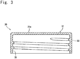
- the molded article 1, particularly when made of plastic is a cap.
- the above cap (indicated entirely at 30) comprises a top panel 31 having a flat surface, and a skirt 33 downwardly extending from the circumferential edge of the top panel 31.
- a thread 35 is formed for fixing the cap 30 onto the outer surface of the mouth of a container (not shown).
- a seal ring or the like for forming a seal is provided, instead of the thread 35, on the inner surface of the top panel 31.
- the above-mentioned plastic cap is generally formed of an olefin resin such as polypropylene or polyethylene. Its heat resistance is low, and it has, formed therein, the thread 35 (or seal ring) or the like which is extremely susceptible to heat deformation. According to the present invention, drying for removal of the solvent can be carried out under mild conditions. With the present invention, therefore, when the inkjet-printed image 3 is to be formed on the top face 31a of the plastic cap (upper surface of the top panel 31), the printed image can be formed at a high speed, with the heat deformation of the cap 3 being effectively prevented. In this manner, effective use can be made of the advantages of the present invention.
- the above cap is further preferably designed such that the top panel having the top face, on which printing is to be done, has a small wall thickness of 2.0 mm or less, particularly 1.5 mm or less.
- the top panel having the top face, on which printing is to be done has a small wall thickness of 2.0 mm or less, particularly 1.5 mm or less.
- the resource-saving point of view for example, there has been a trend toward the wall thinning of caps.
- warpage or the like will occur in the top panel 31 of the cap 30 formed by thermoforming such as injection molding or compression molding. If such warpage occurs, the problem arises that a printed image blurs in the case of printing by press contact with a roll, for example, as in gravure printing.
- the ink receiving layer 5 and the printed image 3 are both formed from flying droplets of ink by the inkjet method. Even when the top face of the cap is satinized in order to impart design properties or reduce friction during transport, moreover, the ink receiving layer 5 and the printed image 3 can be formed at the bottom of concavities of the uneven surface without blurring.
- the site where printing takes place is not limited to the top face of the cap, but the side surface of the molded article can be printed. If the range of printing is a wide range in the circumferential direction of the molded article, the molded article is rotated on its axis, and its side surface can be printed by the method of the present invention.
- the formation of the printed image on the molded article can be performed at a high speed, with thermal deformation of the molded article being effectively prevented, with the result that very high productivity can be ensured.
Landscapes
- Engineering & Computer Science (AREA)
- Mechanical Engineering (AREA)
- Ink Jet Recording Methods And Recording Media Thereof (AREA)
- Ink Jet (AREA)
- Inks, Pencil-Leads, Or Crayons (AREA)
Claims (3)
- Tintenstrahldruckverfahren zum Bilden eines tintenstrahlgedruckten Bildes auf einer Oberfläche eines Formkörpers, umfassend:Bilden einer Tintenaufnahmeschicht auf einem Abschnitt, wo das gedruckte Bild gebildet werden soll, durch Tintenstrahldrucken in Übereinstimmung mit dem gedruckten Bild vor der Bildung des gedruckten Bildes mit einem Tintenstrahl unter Verwendung einer Tinte auf Ölbasis,wobei die Tintenaufnahmeschicht durch Tintenstrahldrucken unter Verwendung der Tinte für eine Aufnahmeschicht gebildet wird, wobei die Tinte Harz vom Nasstyp und in Lösungsmittel dispergierte anorganische feine Teilchen umfasst,wobei die anorganischen feinen Teilchen einen Volumendurchschnitts-Teilchendurchmesser (D50) von 5 µm oder weniger haben und das Harz vom Nasstyp eines ist, in dem eine Volumenvergrößerung aufgrund des Eindringens des Lösungsmittels festgestellt wird, wenn es bei 25 °C in das in der Tinte auf Ölbasis enthaltene Lösungsmittel eingetaucht wird; wobei das mit dem Tintenstrahl gebildete gedruckte Bild ein lokales Bild ist,wobei das lokale Bild ein Schriftzeichen, eine Linie, ein Punkt oder Punkte ist,wobei der Formkörper eine Kappe ist und wobei das tintenstrahlgedruckte Bild auf einer oberen Fläche der Kappe gebildet wird.
- Tintenstrahldruckverfahren nach Anspruch 1, wobei die Kappe aus Kunststoff besteht.
- Tintenstrahldruckverfahren nach Anspruch 2, wobei die obere Fläche der Kunststoffkappe in einer dünnwandigen Deckplatte, die eine Dicke von 2,0 mm oder weniger hat, gebildet wird.
Applications Claiming Priority (3)
| Application Number | Priority Date | Filing Date | Title |
|---|---|---|---|
| JP2012244074 | 2012-11-06 | ||
| JP2012257073 | 2012-11-26 | ||
| PCT/JP2013/079205 WO2014073417A1 (ja) | 2012-11-06 | 2013-10-29 | 成形品へのインクジェット印刷方法 |
Publications (3)
| Publication Number | Publication Date |
|---|---|
| EP2918421A1 EP2918421A1 (de) | 2015-09-16 |
| EP2918421A4 EP2918421A4 (de) | 2016-12-21 |
| EP2918421B1 true EP2918421B1 (de) | 2018-01-31 |
Family
ID=50684526
Family Applications (1)
| Application Number | Title | Priority Date | Filing Date |
|---|---|---|---|
| EP13853618.0A Active EP2918421B1 (de) | 2012-11-06 | 2013-10-29 | Verfahren zum tintenstrahldrucken auf formkörpern |
Country Status (6)
| Country | Link |
|---|---|
| US (1) | US20150298456A1 (de) |
| EP (1) | EP2918421B1 (de) |
| JP (1) | JP6242803B2 (de) |
| KR (1) | KR20150081326A (de) |
| CN (1) | CN104768768B (de) |
| WO (1) | WO2014073417A1 (de) |
Families Citing this family (7)
| Publication number | Priority date | Publication date | Assignee | Title |
|---|---|---|---|---|
| JP2016016533A (ja) * | 2014-07-04 | 2016-02-01 | 日本クロージャー株式会社 | インクジェット印刷が施された印刷品 |
| JP6641691B2 (ja) * | 2014-12-26 | 2020-02-05 | 大日本印刷株式会社 | 複合容器およびその製造方法 |
| JP2018165039A (ja) * | 2017-03-28 | 2018-10-25 | ケイミュー株式会社 | 建材及びその製造方法 |
| JP6380626B1 (ja) | 2017-07-19 | 2018-08-29 | オムロン株式会社 | 樹脂構造体の製造方法および樹脂構造体 |
| CN114206627A (zh) * | 2019-07-23 | 2022-03-18 | 株式会社理光 | 印刷品生产方法和印刷品生产设备以及印刷品 |
| JP7157934B2 (ja) * | 2019-12-24 | 2022-10-21 | 大日本印刷株式会社 | 複合容器およびその製造方法 |
| DE102020132134A1 (de) | 2020-12-03 | 2022-06-09 | Krones Aktiengesellschaft | Direktdruckmaschine |
Family Cites Families (22)
| Publication number | Priority date | Publication date | Assignee | Title |
|---|---|---|---|---|
| JPH0237308B2 (ja) * | 1981-05-12 | 1990-08-23 | Toyo Seikan Kaisha Ltd | Koodomaakunoinjioyobigenjihoho |
| GB9717776D0 (en) * | 1997-08-21 | 1997-10-29 | Procter & Gamble | Printing process and apparatus |
| BR0112196A (pt) * | 2000-07-04 | 2003-07-01 | Furukawa Ken-Ichi | Formação de imagem |
| JP2002283575A (ja) * | 2001-03-22 | 2002-10-03 | Hitachi Service & Engineering (East) Ltd | 多列食品密封カップ印字装置及びその使用方法。 |
| JP2003011342A (ja) | 2001-06-29 | 2003-01-15 | Alcoa Closure Systems Japan Ltd | キャップおよびその印刷方法 |
| US6848781B2 (en) * | 2002-09-30 | 2005-02-01 | Canon Kabushiki Kaisha | Image forming process, image-recorded article, liquid composition and ink-jet recording apparatus |
| JP2005290216A (ja) * | 2004-03-31 | 2005-10-20 | Seiko Epson Corp | インクジェット非水系インクセット、インクカートリッジ、記録装置及び記録物 |
| US7520601B2 (en) * | 2004-10-29 | 2009-04-21 | Agfa Graphics, N.V. | Printing of radiation curable inks into a radiation curable liquid layer |
| EP1652686B1 (de) * | 2004-10-29 | 2008-06-25 | Agfa Graphics N.V. | Druck der strahlungshärtbaren Tinten in eine flüssige strahlungshärtbare Schicht |
| EP1728644B1 (de) * | 2005-06-02 | 2009-01-21 | Agfa Graphics N.V. | Tintenstrahlsicherheitsmarkierung für ein Produkt oder eine Produktverpackung |
| JP2009507692A (ja) * | 2005-09-12 | 2009-02-26 | エレクトロニクス、フォー、イメージング、インコーポレーテッド | グラフィック用途用金属インクジェット印刷システム |
| JP4989870B2 (ja) * | 2005-09-30 | 2012-08-01 | 富士フイルム株式会社 | インクジェット記録用インク組成物、インクジェット記録用インクセット、及びインクジェット画像記録方法 |
| JP2007301871A (ja) * | 2006-05-12 | 2007-11-22 | Kao Corp | 印字のための凹凸面構造 |
| JP4193872B2 (ja) * | 2006-05-19 | 2008-12-10 | ブラザー工業株式会社 | インクジェット記録方法 |
| JP2008213199A (ja) | 2007-03-01 | 2008-09-18 | Matsushita Electric Ind Co Ltd | 熱収縮性積層フィルム、熱収縮性積層フィルムの製造方法、容器、容器の製造方法 |
| JP4766281B2 (ja) * | 2007-09-18 | 2011-09-07 | セイコーエプソン株式会社 | インクジェット記録用非水系インク組成物、インクジェット記録方法および記録物 |
| JP5550059B2 (ja) * | 2008-07-11 | 2014-07-16 | 大日本塗料株式会社 | 画像形成方法及び画像形成物 |
| JP5515650B2 (ja) * | 2008-12-09 | 2014-06-11 | セイコーエプソン株式会社 | 画像記録方法、画像記録システム |
| JP2011062946A (ja) * | 2009-09-18 | 2011-03-31 | Seiko Epson Corp | 記録方法、記録物および白色インク |
| JP5703624B2 (ja) * | 2010-08-11 | 2015-04-22 | セイコーエプソン株式会社 | インクジェット記録方法および記録物 |
| JP5664011B2 (ja) * | 2010-08-11 | 2015-02-04 | セイコーエプソン株式会社 | インクジェット記録方法、インクセットおよび記録物 |
| CN103442813B (zh) * | 2011-03-31 | 2016-10-12 | 大日本涂料株式会社 | 多层涂膜及该多层涂膜的制造方法 |
-
2013
- 2013-10-29 CN CN201380058139.5A patent/CN104768768B/zh active Active
- 2013-10-29 EP EP13853618.0A patent/EP2918421B1/de active Active
- 2013-10-29 KR KR1020157014400A patent/KR20150081326A/ko not_active Application Discontinuation
- 2013-10-29 US US14/440,686 patent/US20150298456A1/en not_active Abandoned
- 2013-10-29 JP JP2014545656A patent/JP6242803B2/ja active Active
- 2013-10-29 WO PCT/JP2013/079205 patent/WO2014073417A1/ja active Application Filing
Non-Patent Citations (1)
| Title |
|---|
| None * |
Also Published As
| Publication number | Publication date |
|---|---|
| JP6242803B2 (ja) | 2017-12-06 |
| WO2014073417A1 (ja) | 2014-05-15 |
| KR20150081326A (ko) | 2015-07-13 |
| CN104768768B (zh) | 2016-11-02 |
| EP2918421A4 (de) | 2016-12-21 |
| JPWO2014073417A1 (ja) | 2016-09-08 |
| EP2918421A1 (de) | 2015-09-16 |
| US20150298456A1 (en) | 2015-10-22 |
| CN104768768A (zh) | 2015-07-08 |
Similar Documents
| Publication | Publication Date | Title |
|---|---|---|
| EP2918421B1 (de) | Verfahren zum tintenstrahldrucken auf formkörpern | |
| JP6117558B2 (ja) | インクジェット印刷用インク、印刷円筒形容器及びその製造方法 | |
| AU686209B2 (en) | Image forming method, process for producing decorative aluminum plate, apparatus for carrying out the process, decorative aluminum plate, and recording medium | |
| JP5636682B2 (ja) | シームレス缶用インキジェット印刷フィルム | |
| US8747969B2 (en) | Coated films for inkjet printing | |
| CN102825937B (zh) | 印刷方法、转印材料及喷墨喷出装置 | |
| JP2015091640A (ja) | 記録方法 | |
| JP6314468B2 (ja) | 印刷缶及びその製造方法 | |
| US9132685B2 (en) | UV ink fixed structure and UV ink printing method | |
| JP2019162870A (ja) | 乾燥装置、液体吐出装置、乾燥方法、及びインクジェット記録装置 | |
| JP2004090596A (ja) | 画像形成方法及び画像形成装置 | |
| JP4738026B2 (ja) | 印刷フィルム貼着缶体の製造方法 | |
| US7275818B2 (en) | Process and materials for marking plastic surfaces | |
| US7416297B2 (en) | Process and materials for marking plastic surfaces | |
| JP2016016533A (ja) | インクジェット印刷が施された印刷品 | |
| JP5482100B2 (ja) | 金属缶用印刷フィルム、その製造方法及び製造装置 | |
| US20180043671A1 (en) | Method Of Applying Hydro-Graphic Film To Articles | |
| WO2021199794A1 (ja) | 印刷物の製造方法、印刷装置及び印刷缶 | |
| JPH08156394A (ja) | 画像形成方法、装飾アルミニウム板の製造方法及び製造装置、装飾アルミニウム板 | |
| WO2024015786A2 (en) | Thermoplastic and thermosetting resin-containing ink compositions and methods for their application |
Legal Events
| Date | Code | Title | Description |
|---|---|---|---|
| PUAI | Public reference made under article 153(3) epc to a published international application that has entered the european phase |
Free format text: ORIGINAL CODE: 0009012 |
|
| 17P | Request for examination filed |
Effective date: 20150505 |
|
| AK | Designated contracting states |
Kind code of ref document: A1 Designated state(s): AL AT BE BG CH CY CZ DE DK EE ES FI FR GB GR HR HU IE IS IT LI LT LU LV MC MK MT NL NO PL PT RO RS SE SI SK SM TR |
|
| AX | Request for extension of the european patent |
Extension state: BA ME |
|
| DAX | Request for extension of the european patent (deleted) | ||
| RA4 | Supplementary search report drawn up and despatched (corrected) |
Effective date: 20161118 |
|
| RIC1 | Information provided on ipc code assigned before grant |
Ipc: B41M 5/50 20060101ALI20161114BHEP Ipc: B65B 61/00 20060101ALI20161114BHEP Ipc: B41M 5/52 20060101ALI20161114BHEP Ipc: B41M 5/00 20060101AFI20161114BHEP Ipc: B41J 2/01 20060101ALI20161114BHEP |
|
| GRAP | Despatch of communication of intention to grant a patent |
Free format text: ORIGINAL CODE: EPIDOSNIGR1 |
|
| STAA | Information on the status of an ep patent application or granted ep patent |
Free format text: STATUS: GRANT OF PATENT IS INTENDED |
|
| INTG | Intention to grant announced |
Effective date: 20170908 |
|
| GRAS | Grant fee paid |
Free format text: ORIGINAL CODE: EPIDOSNIGR3 |
|
| GRAA | (expected) grant |
Free format text: ORIGINAL CODE: 0009210 |
|
| STAA | Information on the status of an ep patent application or granted ep patent |
Free format text: STATUS: THE PATENT HAS BEEN GRANTED |
|
| AK | Designated contracting states |
Kind code of ref document: B1 Designated state(s): AL AT BE BG CH CY CZ DE DK EE ES FI FR GB GR HR HU IE IS IT LI LT LU LV MC MK MT NL NO PL PT RO RS SE SI SK SM TR |
|
| REG | Reference to a national code |
Ref country code: CH Ref legal event code: NV Representative=s name: VENI GMBH, CH Ref country code: GB Ref legal event code: FG4D Ref country code: CH Ref legal event code: EP |
|
| REG | Reference to a national code |
Ref country code: AT Ref legal event code: REF Ref document number: 966988 Country of ref document: AT Kind code of ref document: T Effective date: 20180215 |
|
| REG | Reference to a national code |
Ref country code: IE Ref legal event code: FG4D |
|
| REG | Reference to a national code |
Ref country code: DE Ref legal event code: R096 Ref document number: 602013032808 Country of ref document: DE |
|
| REG | Reference to a national code |
Ref country code: NL Ref legal event code: MP Effective date: 20180131 |
|
| REG | Reference to a national code |
Ref country code: LT Ref legal event code: MG4D |
|
| REG | Reference to a national code |
Ref country code: AT Ref legal event code: MK05 Ref document number: 966988 Country of ref document: AT Kind code of ref document: T Effective date: 20180131 |
|
| PG25 | Lapsed in a contracting state [announced via postgrant information from national office to epo] |
Ref country code: NO Free format text: LAPSE BECAUSE OF FAILURE TO SUBMIT A TRANSLATION OF THE DESCRIPTION OR TO PAY THE FEE WITHIN THE PRESCRIBED TIME-LIMIT Effective date: 20180430 Ref country code: ES Free format text: LAPSE BECAUSE OF FAILURE TO SUBMIT A TRANSLATION OF THE DESCRIPTION OR TO PAY THE FEE WITHIN THE PRESCRIBED TIME-LIMIT Effective date: 20180131 Ref country code: NL Free format text: LAPSE BECAUSE OF FAILURE TO SUBMIT A TRANSLATION OF THE DESCRIPTION OR TO PAY THE FEE WITHIN THE PRESCRIBED TIME-LIMIT Effective date: 20180131 Ref country code: FI Free format text: LAPSE BECAUSE OF FAILURE TO SUBMIT A TRANSLATION OF THE DESCRIPTION OR TO PAY THE FEE WITHIN THE PRESCRIBED TIME-LIMIT Effective date: 20180131 Ref country code: HR Free format text: LAPSE BECAUSE OF FAILURE TO SUBMIT A TRANSLATION OF THE DESCRIPTION OR TO PAY THE FEE WITHIN THE PRESCRIBED TIME-LIMIT Effective date: 20180131 Ref country code: LT Free format text: LAPSE BECAUSE OF FAILURE TO SUBMIT A TRANSLATION OF THE DESCRIPTION OR TO PAY THE FEE WITHIN THE PRESCRIBED TIME-LIMIT Effective date: 20180131 |
|
| PG25 | Lapsed in a contracting state [announced via postgrant information from national office to epo] |
Ref country code: BG Free format text: LAPSE BECAUSE OF FAILURE TO SUBMIT A TRANSLATION OF THE DESCRIPTION OR TO PAY THE FEE WITHIN THE PRESCRIBED TIME-LIMIT Effective date: 20180430 Ref country code: IS Free format text: LAPSE BECAUSE OF FAILURE TO SUBMIT A TRANSLATION OF THE DESCRIPTION OR TO PAY THE FEE WITHIN THE PRESCRIBED TIME-LIMIT Effective date: 20180531 Ref country code: SE Free format text: LAPSE BECAUSE OF FAILURE TO SUBMIT A TRANSLATION OF THE DESCRIPTION OR TO PAY THE FEE WITHIN THE PRESCRIBED TIME-LIMIT Effective date: 20180131 Ref country code: GR Free format text: LAPSE BECAUSE OF FAILURE TO SUBMIT A TRANSLATION OF THE DESCRIPTION OR TO PAY THE FEE WITHIN THE PRESCRIBED TIME-LIMIT Effective date: 20180501 Ref country code: LV Free format text: LAPSE BECAUSE OF FAILURE TO SUBMIT A TRANSLATION OF THE DESCRIPTION OR TO PAY THE FEE WITHIN THE PRESCRIBED TIME-LIMIT Effective date: 20180131 Ref country code: AT Free format text: LAPSE BECAUSE OF FAILURE TO SUBMIT A TRANSLATION OF THE DESCRIPTION OR TO PAY THE FEE WITHIN THE PRESCRIBED TIME-LIMIT Effective date: 20180131 Ref country code: PL Free format text: LAPSE BECAUSE OF FAILURE TO SUBMIT A TRANSLATION OF THE DESCRIPTION OR TO PAY THE FEE WITHIN THE PRESCRIBED TIME-LIMIT Effective date: 20180131 Ref country code: RS Free format text: LAPSE BECAUSE OF FAILURE TO SUBMIT A TRANSLATION OF THE DESCRIPTION OR TO PAY THE FEE WITHIN THE PRESCRIBED TIME-LIMIT Effective date: 20180131 |
|
| PG25 | Lapsed in a contracting state [announced via postgrant information from national office to epo] |
Ref country code: AL Free format text: LAPSE BECAUSE OF FAILURE TO SUBMIT A TRANSLATION OF THE DESCRIPTION OR TO PAY THE FEE WITHIN THE PRESCRIBED TIME-LIMIT Effective date: 20180131 Ref country code: RO Free format text: LAPSE BECAUSE OF FAILURE TO SUBMIT A TRANSLATION OF THE DESCRIPTION OR TO PAY THE FEE WITHIN THE PRESCRIBED TIME-LIMIT Effective date: 20180131 Ref country code: EE Free format text: LAPSE BECAUSE OF FAILURE TO SUBMIT A TRANSLATION OF THE DESCRIPTION OR TO PAY THE FEE WITHIN THE PRESCRIBED TIME-LIMIT Effective date: 20180131 |
|
| REG | Reference to a national code |
Ref country code: DE Ref legal event code: R097 Ref document number: 602013032808 Country of ref document: DE |
|
| PG25 | Lapsed in a contracting state [announced via postgrant information from national office to epo] |
Ref country code: CZ Free format text: LAPSE BECAUSE OF FAILURE TO SUBMIT A TRANSLATION OF THE DESCRIPTION OR TO PAY THE FEE WITHIN THE PRESCRIBED TIME-LIMIT Effective date: 20180131 Ref country code: SM Free format text: LAPSE BECAUSE OF FAILURE TO SUBMIT A TRANSLATION OF THE DESCRIPTION OR TO PAY THE FEE WITHIN THE PRESCRIBED TIME-LIMIT Effective date: 20180131 Ref country code: DK Free format text: LAPSE BECAUSE OF FAILURE TO SUBMIT A TRANSLATION OF THE DESCRIPTION OR TO PAY THE FEE WITHIN THE PRESCRIBED TIME-LIMIT Effective date: 20180131 Ref country code: SK Free format text: LAPSE BECAUSE OF FAILURE TO SUBMIT A TRANSLATION OF THE DESCRIPTION OR TO PAY THE FEE WITHIN THE PRESCRIBED TIME-LIMIT Effective date: 20180131 |
|
| PLBE | No opposition filed within time limit |
Free format text: ORIGINAL CODE: 0009261 |
|
| STAA | Information on the status of an ep patent application or granted ep patent |
Free format text: STATUS: NO OPPOSITION FILED WITHIN TIME LIMIT |
|
| 26N | No opposition filed |
Effective date: 20181102 |
|
| PG25 | Lapsed in a contracting state [announced via postgrant information from national office to epo] |
Ref country code: SI Free format text: LAPSE BECAUSE OF FAILURE TO SUBMIT A TRANSLATION OF THE DESCRIPTION OR TO PAY THE FEE WITHIN THE PRESCRIBED TIME-LIMIT Effective date: 20180131 |
|
| REG | Reference to a national code |
Ref country code: BE Ref legal event code: MM Effective date: 20181031 |
|
| PG25 | Lapsed in a contracting state [announced via postgrant information from national office to epo] |
Ref country code: MC Free format text: LAPSE BECAUSE OF FAILURE TO SUBMIT A TRANSLATION OF THE DESCRIPTION OR TO PAY THE FEE WITHIN THE PRESCRIBED TIME-LIMIT Effective date: 20180131 Ref country code: LU Free format text: LAPSE BECAUSE OF NON-PAYMENT OF DUE FEES Effective date: 20181029 |
|
| REG | Reference to a national code |
Ref country code: IE Ref legal event code: MM4A |
|
| PG25 | Lapsed in a contracting state [announced via postgrant information from national office to epo] |
Ref country code: FR Free format text: LAPSE BECAUSE OF NON-PAYMENT OF DUE FEES Effective date: 20181031 Ref country code: BE Free format text: LAPSE BECAUSE OF NON-PAYMENT OF DUE FEES Effective date: 20181031 |
|
| PG25 | Lapsed in a contracting state [announced via postgrant information from national office to epo] |
Ref country code: IE Free format text: LAPSE BECAUSE OF NON-PAYMENT OF DUE FEES Effective date: 20181029 |
|
| PG25 | Lapsed in a contracting state [announced via postgrant information from national office to epo] |
Ref country code: MT Free format text: LAPSE BECAUSE OF NON-PAYMENT OF DUE FEES Effective date: 20181029 |
|
| PG25 | Lapsed in a contracting state [announced via postgrant information from national office to epo] |
Ref country code: TR Free format text: LAPSE BECAUSE OF FAILURE TO SUBMIT A TRANSLATION OF THE DESCRIPTION OR TO PAY THE FEE WITHIN THE PRESCRIBED TIME-LIMIT Effective date: 20180131 |
|
| PG25 | Lapsed in a contracting state [announced via postgrant information from national office to epo] |
Ref country code: PT Free format text: LAPSE BECAUSE OF FAILURE TO SUBMIT A TRANSLATION OF THE DESCRIPTION OR TO PAY THE FEE WITHIN THE PRESCRIBED TIME-LIMIT Effective date: 20180131 |
|
| PG25 | Lapsed in a contracting state [announced via postgrant information from national office to epo] |
Ref country code: CY Free format text: LAPSE BECAUSE OF FAILURE TO SUBMIT A TRANSLATION OF THE DESCRIPTION OR TO PAY THE FEE WITHIN THE PRESCRIBED TIME-LIMIT Effective date: 20180131 Ref country code: MK Free format text: LAPSE BECAUSE OF NON-PAYMENT OF DUE FEES Effective date: 20180131 Ref country code: HU Free format text: LAPSE BECAUSE OF FAILURE TO SUBMIT A TRANSLATION OF THE DESCRIPTION OR TO PAY THE FEE WITHIN THE PRESCRIBED TIME-LIMIT; INVALID AB INITIO Effective date: 20131029 |
|
| PGFP | Annual fee paid to national office [announced via postgrant information from national office to epo] |
Ref country code: IT Payment date: 20230913 Year of fee payment: 11 Ref country code: GB Payment date: 20230907 Year of fee payment: 11 |
|
| PGFP | Annual fee paid to national office [announced via postgrant information from national office to epo] |
Ref country code: DE Payment date: 20230906 Year of fee payment: 11 Ref country code: CH Payment date: 20231102 Year of fee payment: 11 |