EP2916687B1 - Élément d'assemblage d'angle - Google Patents
Élément d'assemblage d'angle Download PDFInfo
- Publication number
- EP2916687B1 EP2916687B1 EP13770635.4A EP13770635A EP2916687B1 EP 2916687 B1 EP2916687 B1 EP 2916687B1 EP 13770635 A EP13770635 A EP 13770635A EP 2916687 B1 EP2916687 B1 EP 2916687B1
- Authority
- EP
- European Patent Office
- Prior art keywords
- frame
- corner connector
- projection
- connector according
- spring
- Prior art date
- Legal status (The legal status is an assumption and is not a legal conclusion. Google has not performed a legal analysis and makes no representation as to the accuracy of the status listed.)
- Active
Links
- 239000002184 metal Substances 0.000 claims description 8
- 230000008719 thickening Effects 0.000 claims description 7
- 230000002787 reinforcement Effects 0.000 claims 1
- 230000000284 resting effect Effects 0.000 claims 1
- 238000013459 approach Methods 0.000 description 11
- 238000005553 drilling Methods 0.000 description 4
- 238000010276 construction Methods 0.000 description 3
- 239000000243 solution Substances 0.000 description 3
- 230000002349 favourable effect Effects 0.000 description 2
- 238000004519 manufacturing process Methods 0.000 description 2
- 230000000903 blocking effect Effects 0.000 description 1
- 238000011156 evaluation Methods 0.000 description 1
- 210000003746 feather Anatomy 0.000 description 1
- 238000001746 injection moulding Methods 0.000 description 1
- 238000003780 insertion Methods 0.000 description 1
- 230000037431 insertion Effects 0.000 description 1
- 239000000463 material Substances 0.000 description 1
- 239000007787 solid Substances 0.000 description 1
- 239000003351 stiffener Substances 0.000 description 1
Images


Classifications
-
- A—HUMAN NECESSITIES
- A47—FURNITURE; DOMESTIC ARTICLES OR APPLIANCES; COFFEE MILLS; SPICE MILLS; SUCTION CLEANERS IN GENERAL
- A47B—TABLES; DESKS; OFFICE FURNITURE; CABINETS; DRAWERS; GENERAL DETAILS OF FURNITURE
- A47B47/00—Cabinets, racks or shelf units, characterised by features related to dismountability or building-up from elements
- A47B47/0008—Three-dimensional corner connectors, the legs thereof being received within hollow, elongated frame members
Definitions
- the invention relates to a corner connector, comprising a first cube-shaped base body having on a first cube surface a closed surface and two adjoining second and third closed surfaces at right angles to each other and to the first cube surface, while the cube surface is opposite the second and third surfaces in each case an approach with prismatic outer cross-section for attaching a pipe profile end adapted to the outer cross-section of the neck inner cross-section, wherein the approach over its alignment line has resiliently projecting holding elements which protrude into a breakthrough formed near the pipe profile end and to the create a breakthrough edge to hold the tube end axially in place against the cube face.
- Such a corner connector is from the FR 2 674 581 A1 or from the DE 91 05 664 U1 essentially known.
- the object of the invention is to provide a corner connector which does not have these disadvantages and which can be arranged in a frame, in particular for the simplified construction of a sheet metal cabinet or sheet metal housing.
- Fig. 30A to use and to arrange a displaceable in a transversely to the tube profile axis channel slidable carriage, wherein the one end of the carriage protrudes in working position due to the spring tension from the channel with two inclined surfaces, wherein the one inclined surface with the thrust direction of the carriage a first , larger angle forms as inlet surface and the second inclined surface corresponding to a smaller angle forms as a holding surface.
- the channel for the carriage through the cross section of the approach passes through, as well as in the WO document 2005/36083209 a continuous opening for the carriage is present.
- the spring force is formed by a spiral spring, which is arranged in an opening of the carriage and has a thickness of the carriage superior diameter.
- the channel is drilled in the region of the spring to support the spring by the shoulder formed by the hole end.
- the inner end of the bore is reduced in diameter according to yet another embodiment to clamp the supported end of the spring and thus to secure the spring against falling out.
- the cross-section of the neck has jumped back to such a degree that corresponds to the axial extent of the inclined surfaces, wherein the pipe end has a corresponding thickening in cross section.
- a cube surface of the main body may be provided with an axial bore threaded to connect a further base body to the first base body by means of a screw, or to an existing frame, such as the base frame or roof frame of a rack or cabinet or housing.
- the corner joint can be loosened again by means of a plug which can be received in the opening of the pipe profile end and has such dimensions that the reaching-in part can push the slide out of the opening and detach the pipe profile piece from the socket.
- the cube-shaped base body and the approaches can be used to save material hollow body, possibly with thickening and stiffening struts inside the body.
- the corner connector can also be designed such that the lugs are held by means of two holding elements, wherein the holding elements are arranged obliquely opposite one another, wherein the holding elements are in opposite directions.
- the invention also includes or can be used in a frame, in particular for a sheet metal cabinet or sheet metal housing, with a base formed as a frame and / or designed as a frame roof, and / or designed as a frame door, rear wall or side wall, wherein the Frame is rectangular and carries at its four corners recordings in which vertical corner profiles can be received by plugging and are held by corner connectors according to one of claims 1 to 10.
- the base or roof frame is a large, deep-drawn sheet metal part, or it is made of individual, z. B. welded together four parts frame parts, to which frame the four shots are screwed.
- the frame is characterized in that the four receptacles are formed with the carriage-shaped support members as flanges, which are arranged rotated by 90 degrees to each other and which are connected by screws with the four frame sections and connect them like a bridge.
- the frame portion may consist of a folded profile section into which the flanges are fitting inserted.
- the frame sections after mounting a Dachplatten- or bottom plate or door, rear wall or side plate clamped record.
- the flange parts may each have a central threaded bore into which a cap screw, eyelet or an adjustable foot can be screwed, for fastening the receptacle to the frame.
- the receptacles of the frame each have a central threaded bore into which a cap screw, eye or adjustable foot can be screwed, for fastening the receptacle to the corner connector.
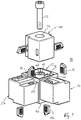
- a corner connector 10 comprising a cube-shaped base body 12 having on a first cube surface 14 a closed surface and two adjacent, mutually and the first cube surface perpendicularly extending second and third closed surfaces 16, 18, while of the second and third cube surface 16, 18 opposite cube surface 20, 22 each have a projection 24, 26 each with a prismatic, in the profile of a substantially rectangular outer cross-section for attaching a tubular profile end 28, 30, see Fig.
- the tube profile end has an inner cross section or inner profile 32 adapted to the outer cross section of the projection 24, 26, the projection 24 being resilient over the alignment line 34 projecting holding elements 36 each projecting into a breakthrough 38 formed near the tubular profile end 28 and bear against the breakthrough edge 40, whereby the tube profile end 28 is axially held on the projection 24 in position, wherein the tube profile end is axially supported on the cube surface.
- the holding element 36 Represents a arranged in a transverse to the tube profile axis 42 channel 44 displaceable against spring force slide, the one end 48 of the carriage 36 in working position due to the spring tension of the spring 46 from the channel 44 with two inclined surfaces 50, 52 resiliently protrudes, wherein the an inclined surface 50 with the thrust direction 58 of the carriage 36 forms a first larger angle 54 as an inlet surface and the second inclined surface 52 corresponding to a smaller angle 56 between the inclined surface 52 and the thrust direction 58 forms the support surface 52, wherein the second inclined surface 52 with the first inclined surface forms approximately a right angle.
- the carriage 36 has a rectangular opening 92, in which the spring 46 can be inserted laterally, wherein a protruding into the opening 92 approach 94 prevents falling out of the spring 46 during assembly.
- the cross section of the channel 44 and the cross section of the carriage 36 guided therein have the basic shape of a rectangle.
- the area of the spring is drilled out, see for example the right side of the projection 26 in FIG Fig. 1 to support the spring through the shoulder formed by the bore end 60, as shown in FIG Fig. 3B
- the carriage 36 is inserted against the force of the spring 46 by a plug 62 or, in which the plug 62 was inserted into the opening 38 and pushed in the direction of the arrow 58. Since the channel 44 is narrower than the width of the diameter of the spring 36, when drilling for the spring two opposing bottom surfaces, which is now broken by the channel of rectangular cross section and forms the guide for the carriage 36.
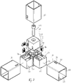
- the main body 12 can according to Fig. 1 on its sixth surface 66 a bore 68th having an axial thread to attach a further projection 70 when it has an axial bore 74 to screw by means of a screw 72 the lug 70 on the base body 12, for example, in addition to, for example, two horizontal struts 28, 30 still mount a vertical strut 90, for example to be able to.
- the base body 12 as the lugs 24, 26, 70 is not solid, but as a hollow body with thickening for example horizontal struts 76, 78 provided.
- the pipe section 28 may have a stiffener 76, which is preferably in the region with the opening 38. This increases the stability.
- the projection 24 has at the corresponding point a recess 82, which has the advantage that the inclined surfaces 52, 50 extend far into the cavity 38 without that they reach the surface of the pipe section 28 and interfere. It is advantageous if the lugs 24, 26, 70 each have two holding elements 36 which are arranged for reasons of symmetry with greater strength to each other a maximum distance because of the larger lever arm and also work in opposite directions, such as Fig. 1 makes it clear where the approach 24 has fasteners 36, 136.
- a projection 70 can be screwed with a screw 172 and a cover plate 84 on the sixth side of the body 12, see Fig. 5 , This arrangement is preferable if no third vertical tube profile piece is needed.
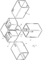
- Fig. 8 shows a simplified embodiment of the roof or base frame made of welded together profile pieces 110, wherein the welded frame, here to form a cabinet roof, is provided at its four corners with lugs or receptacles 170, on the perpendicular Eckprofile 190 attachable and by means of slide-shaped holding elements 136 are held in position, which retract into the openings 138 near the profile ends.
- the recordings are held by means of cap screws 172, which is guided through a round hole 111 in the frame and screwed into a threaded bore 168 in the receptacle 170.
- two lugs 98 are projecting on the support surface 113 of the receptacle 170, which penetrate after mounting in bores 115 in the frame 110 and so form a rotation lock.
- Fig. 9 shows another embodiment of a frame 210, which consists of four mutually perpendicular sections 117, 119, 121, 123, which are interconnected by flanges 125 having on the bottom receptacles 270 for carriage-shaped holding elements 236, wherein the flanges by means of screws 127th are bolted to the ends of the sections 117, 119, 121 and 123, for which purpose the sections with through-round holes 129 and the flanges can be provided with threaded holes 131.
- the receptacles 270 may also have threaded holes 68 for screwing in a lifting eye 135.
- roof frame 210 is a base frame in which instead of the lifting eyelets adjustable feet can be screwed.
- the frame sections may consist of folded profile sections 117, 119, 121, 123, into which the flanges 125 are fittingly insertable.
- the frame sections can accommodate a roof or base plate after mounting.
- Fig. 8 and 9 It may not just be a designed as a frame floor or roof of a cabinet or housing, but act just as well to a trained as a frame side wall, rear wall or door.
- a consisting of such frames and parts cabinet or housing can be much narrower, in particular much flatter pack than conventional cabinets and housing and thus much easier and cheaper store and ship, the structure is very simple and without special tools is possible, so that the end customer Assembly can be done by yourself.
- the invention can be evaluated commercially in control cabinet construction.
Landscapes
- Mutual Connection Of Rods And Tubes (AREA)
- Furniture Connections (AREA)
Claims (16)
- Connecteur d'angle (10), comprenant un corps de base (12) en forme de cube qui, sur une première surface (14) du cube, présente une surface fermée, et deux surfaces qui s'y raccordent, à savoir une deuxième surface (16) et une troisième surface (18) s'étendant à angle droit l'une par rapport à l'autre et par rapport à la première surface de cube (14), tandis qu'un décrochement respectif de section transversale extérieure prismatique, destiné à enficher une extrémité de tube avec une section transversale intérieure (32) adaptée à la section transversale extérieure du décrochement part des surfaces de cube opposées à la deuxième et à la troisième surface, dans lequel le décrochement présente des éléments de retenue (36) qui font saillie élastiquement au-delà de sa ligne d'alignement (34), qui pénètrent dans une traversée (38) formée par l'extrémité de tube et qui s'appuient contre le bord (40) de la traversée afin de maintenir en position l'extrémité de tube (28, 30) axialement en appui contre la surface de paroi (20, 21), caractérisé en ce que l'élément de retenue (36) constitue un chariot (48) mobile à l'encontre d'une force de ressort (46) dans un canal (44) disposé transversalement à l'axe de tube (42), qui, en position de travail, dépasse par deux surfaces obliques hors du canal en raison de la sollicitation par le ressort,
et en ce qu'à titre de surface d'entrée (52), la surface oblique forme avec la direction de translation du chariot (48) un premier angle plus grand (54), et à titre de surface de retenue (50), la seconde surface oblique forme un angle d'autant plus petit (56). - Connecteur d'angle selon la revendication 1, caractérisé en ce que le canal (44) traverse la section transversale du décrochement (26).
- Connecteur d'angle selon la revendication 2, caractérisé en ce que la forcé de ressort (46) est formée par un ressort spiralé (46) qui est agencé dans une traversée (92) du chariot (36) et présente un diamètre (84) dépassant l'épaisseur du chariot (36).
- Connecteur d'angle selon la revendication 3, caractérisé en ce que le chariot est percé dans la zone du ressort (60) pour soutenir le ressort (60) par l'épaulement formé par l'extrémité du perçage.
- Connecteur d'angle selon la revendication 4, caractérisé en ce qu'à l'extrémité intérieure du perçage, le ressort (60) est coincé par réduction du diamètre (84) du perçage et ainsi il est bloqué à l'encontre d'une chute.
- Connecteur d'angle selon l'une des revendications 1 à 5, caractérisé en ce que dans la zone de l'élément de retenue (36), la section transversale du décrochement est en retrait d'une certaine valeur (82), de sorte que les surfaces obliques (50, 52) sont à découvert, et que la section transversale du tube présente un épaississement correspondant (80).
- Connecteur d'angle selon l'une des revendications 1 à 6, caractérisé en ce qu'une surface du cube (66) du corps de base (12) est pourvue d'un perçage axial (68) taraudé, afin de raccorder un autre décrochement (70) au corps de base (12).
- Connecteur d'angle selon l'une des revendications 1 à 7, caractérisé en ce que la partie du chariot (36) pénétrant dans la traversée (38) de l'extrémité de tube est rétractable au moyen d'un élément d'enfichage (62) et permet de détacher l'élément profilé du tube (28) vis-à-vis du décrochement (24).
- Connecteur d'angle selon l'une des revendications 1 à 8, caractérisé en ce que le cube (12) et/ou les décrochements (24, 26) sont des corps creux le cas échéant avec des épaississements et des entretoises de rigidification (76, 78).
- Connecteur d'angle selon l'une des revendications 1 à 9, caractérisé en ce que le décrochement (24) comprend deux éléments de retenue (36, 136) s'étendant en sens opposés et agencés en oblique à l'opposé l'un de l'autre.
- Bâti formant cadre, en particulier pour une armoire en tôle ou un boîtier en tôle, comportant une base réalisée sous forme de cadre (110) et/ou un toit réalisé sous forme de cadre (110), caractérisé en ce que le cadre (110) est constitué par quatre connecteurs d'angle (10, 110, 210) selon l'une des revendications 1 à 10, qui porte dans ses quatre coins des décrochements (170) ou des récepteurs sur lesquels peuvent venir s'enficher les profilés d'angle verticaux (190).
- Bâti formant cadre selon la revendication 11, caractérisé en ce que le cadre est une grande pièce en tôle emboutie ou est assemblé par soudage à partir de pièces individuelles, par exemple constituées des quatre parties de cadre ou portions (110), cadre sur lequel sont vissés les quatre récepteurs (170).
- Bâti formant cadre selon la revendication 11, caractérisé en ce que les quatre récepteurs (270) pour les éléments de retenue sont des brides (125) placées à 90° les unes par rapport aux autres qui sont reliées aux quatre portions de cadre (117, 110, 121, 123) par des vis (127) et qui relient celles-ci.
- Bâti formant cadre selon la revendication 13, caractérisé en ce que les portions de cadre (117, 119, 121, 123) sont constituées par des portions profilées pliées dans lesquelles peuvent s'introduire les brides (125) de façon ajustée.
- Bâti formant cadre selon la revendication 14, caractérisé en ce qu'une fois montées, les portions de cadre (117, 119, 121, 123) peuvent recevoir une plaque de toit ou une plaque de sol en la coinçant.
- Bâti formant cadre selon l'une des revendications 13 à 15, caractérisé en ce que les récepteurs sont des éléments de bride qui présentent chacun un perçage taraudé central (68), dans lequel peut se visser une vis à tête, un oeillet de support (135) ou un pied de support.
Applications Claiming Priority (2)
| Application Number | Priority Date | Filing Date | Title |
|---|---|---|---|
| DE201220010584 DE202012010584U1 (de) | 2012-11-07 | 2012-11-07 | Eckverbinder |
| PCT/EP2013/002678 WO2014072004A1 (fr) | 2012-11-07 | 2013-09-06 | Élément d'assemblage d'angle |
Publications (2)
| Publication Number | Publication Date |
|---|---|
| EP2916687A1 EP2916687A1 (fr) | 2015-09-16 |
| EP2916687B1 true EP2916687B1 (fr) | 2016-12-07 |
Family
ID=49263290
Family Applications (1)
| Application Number | Title | Priority Date | Filing Date |
|---|---|---|---|
| EP13770635.4A Active EP2916687B1 (fr) | 2012-11-07 | 2013-09-06 | Élément d'assemblage d'angle |
Country Status (3)
| Country | Link |
|---|---|
| EP (1) | EP2916687B1 (fr) |
| DE (1) | DE202012010584U1 (fr) |
| WO (1) | WO2014072004A1 (fr) |
Families Citing this family (3)
| Publication number | Priority date | Publication date | Assignee | Title |
|---|---|---|---|---|
| CN108127272B (zh) * | 2018-01-24 | 2024-04-12 | 涿州皓原箔业有限公司 | 一种用于铝箔加工的激光切割打孔装置 |
| CN108302104B (zh) * | 2018-02-09 | 2024-04-09 | 宁波积家创意家居设计有限公司 | 一种用于连接方管的膨胀扣 |
| CN114388958B (zh) * | 2022-03-23 | 2022-07-05 | 宁德时代新能源科技股份有限公司 | 电池的箱体、电池及用电装置 |
Family Cites Families (5)
| Publication number | Priority date | Publication date | Assignee | Title |
|---|---|---|---|---|
| US3472539A (en) * | 1969-01-02 | 1969-10-14 | Streater Ind Inc | Tubular frame joint member |
| US4323319A (en) * | 1977-01-17 | 1982-04-06 | Adams Bevoley C | Structural connecting member |
| FR2674581B1 (fr) | 1991-03-26 | 1993-06-25 | Legrand Sa | Dispositif d'assemblage pour profiles creux. |
| DE9105664U1 (fr) * | 1991-05-07 | 1991-07-04 | Yang, Tian-Show, Tai Ping Hsiang, Taichung, Tw | |
| WO2005000003A2 (fr) | 2003-06-25 | 2005-01-06 | Universal Electronics Inc. | Systeme et procede de surveillance de transmissions telecommandees |
-
2012
- 2012-11-07 DE DE201220010584 patent/DE202012010584U1/de not_active Expired - Lifetime
-
2013
- 2013-09-06 WO PCT/EP2013/002678 patent/WO2014072004A1/fr active Application Filing
- 2013-09-06 EP EP13770635.4A patent/EP2916687B1/fr active Active
Non-Patent Citations (1)
| Title |
|---|
| None * |
Also Published As
| Publication number | Publication date |
|---|---|
| EP2916687A1 (fr) | 2015-09-16 |
| WO2014072004A1 (fr) | 2014-05-15 |
| DE202012010584U1 (de) | 2014-02-12 |
Similar Documents
| Publication | Publication Date | Title |
|---|---|---|
| EP3175127B1 (fr) | Raccord d'angle pour éléments profilés en forme de barre | |
| DE202017107404U1 (de) | Knotenverbinder für Profilsysteme oder dergleichen | |
| EP3613931B1 (fr) | Module de bande destiné au raccordement mobile par charnière autour d'un axe de charnière d'un battant sur un cadre | |
| DE2460382C2 (de) | Bausatz mit wenigstens einem Knotenelement | |
| EP2916687B1 (fr) | Élément d'assemblage d'angle | |
| DE202009014463U1 (de) | Schutzzaun | |
| DE3014507C2 (fr) | ||
| DE102013000624A1 (de) | Mutter zum Befestigen von Komponenten an einem profilierten Element über Schraubmittel und Verfahren zu deren Montage | |
| DE102013101491A1 (de) | Höheneinstellbare Rundstangenführung | |
| EP3406916B1 (fr) | Équerre pour profilés de support | |
| DE2920320A1 (de) | Gehaeuse | |
| DE102010008697A1 (de) | Verbindungssystem | |
| DE2327527A1 (de) | Konstruktionselement | |
| DE202008016386U1 (de) | Verbindungsvorrichtung | |
| EP2245318B1 (fr) | Noeuds d' assemblage pour éléments profilés | |
| DE202012001047U1 (de) | Gestellrahmen eines Schaltschranks oder dergleichen Racks | |
| DE102014119021A1 (de) | Anordnung zum Befestigen eines Pfostens aus Kunststoff an einer Rahmenleiste eines Fensters oder einer Türe mittels eines Pfostenverbinders | |
| DE202012010397U1 (de) | Verbindungsvorrichtung | |
| EP0833030B1 (fr) | Paumelle pour portes, fenêtres ou similaires | |
| EP2453099B1 (fr) | Assemblage d'angle | |
| DE202012104771U1 (de) | Profilverbinder | |
| DE2738321A1 (de) | Verbindungskupplung fuer rohrteile | |
| DE2002631B1 (de) | Rahmen fuer Fenster,Tueren od.dgl. | |
| DE3147092A1 (de) | Montagesystem mit wenigstens einem eckbogenelement | |
| DE202009003162U1 (de) | Zapfen zum Einstecken in ein Zapfenloch |
Legal Events
| Date | Code | Title | Description |
|---|---|---|---|
| PUAI | Public reference made under article 153(3) epc to a published international application that has entered the european phase |
Free format text: ORIGINAL CODE: 0009012 |
|
| 17P | Request for examination filed |
Effective date: 20150417 |
|
| AK | Designated contracting states |
Kind code of ref document: A1 Designated state(s): AL AT BE BG CH CY CZ DE DK EE ES FI FR GB GR HR HU IE IS IT LI LT LU LV MC MK MT NL NO PL PT RO RS SE SI SK SM TR |
|
| AX | Request for extension of the european patent |
Extension state: BA ME |
|
| DAX | Request for extension of the european patent (deleted) | ||
| GRAP | Despatch of communication of intention to grant a patent |
Free format text: ORIGINAL CODE: EPIDOSNIGR1 |
|
| INTG | Intention to grant announced |
Effective date: 20160629 |
|
| GRAJ | Information related to disapproval of communication of intention to grant by the applicant or resumption of examination proceedings by the epo deleted |
Free format text: ORIGINAL CODE: EPIDOSDIGR1 |
|
| GRAR | Information related to intention to grant a patent recorded |
Free format text: ORIGINAL CODE: EPIDOSNIGR71 |
|
| GRAS | Grant fee paid |
Free format text: ORIGINAL CODE: EPIDOSNIGR3 |
|
| GRAA | (expected) grant |
Free format text: ORIGINAL CODE: 0009210 |
|
| INTC | Intention to grant announced (deleted) | ||
| INTG | Intention to grant announced |
Effective date: 20161027 |
|
| AK | Designated contracting states |
Kind code of ref document: B1 Designated state(s): AL AT BE BG CH CY CZ DE DK EE ES FI FR GB GR HR HU IE IS IT LI LT LU LV MC MK MT NL NO PL PT RO RS SE SI SK SM TR |
|
| REG | Reference to a national code |
Ref country code: GB Ref legal event code: FG4D Free format text: NOT ENGLISH |
|
| REG | Reference to a national code |
Ref country code: CH Ref legal event code: EP Ref country code: AT Ref legal event code: REF Ref document number: 850955 Country of ref document: AT Kind code of ref document: T Effective date: 20161215 |
|
| REG | Reference to a national code |
Ref country code: IE Ref legal event code: FG4D Free format text: LANGUAGE OF EP DOCUMENT: GERMAN |
|
| REG | Reference to a national code |
Ref country code: DE Ref legal event code: R096 Ref document number: 502013005670 Country of ref document: DE |
|
| PG25 | Lapsed in a contracting state [announced via postgrant information from national office to epo] |
Ref country code: LV Free format text: LAPSE BECAUSE OF FAILURE TO SUBMIT A TRANSLATION OF THE DESCRIPTION OR TO PAY THE FEE WITHIN THE PRESCRIBED TIME-LIMIT Effective date: 20161207 |
|
| REG | Reference to a national code |
Ref country code: LT Ref legal event code: MG4D |
|
| REG | Reference to a national code |
Ref country code: NL Ref legal event code: MP Effective date: 20161207 |
|
| PG25 | Lapsed in a contracting state [announced via postgrant information from national office to epo] |
Ref country code: SE Free format text: LAPSE BECAUSE OF FAILURE TO SUBMIT A TRANSLATION OF THE DESCRIPTION OR TO PAY THE FEE WITHIN THE PRESCRIBED TIME-LIMIT Effective date: 20161207 Ref country code: NO Free format text: LAPSE BECAUSE OF FAILURE TO SUBMIT A TRANSLATION OF THE DESCRIPTION OR TO PAY THE FEE WITHIN THE PRESCRIBED TIME-LIMIT Effective date: 20170307 Ref country code: GR Free format text: LAPSE BECAUSE OF FAILURE TO SUBMIT A TRANSLATION OF THE DESCRIPTION OR TO PAY THE FEE WITHIN THE PRESCRIBED TIME-LIMIT Effective date: 20170308 Ref country code: LT Free format text: LAPSE BECAUSE OF FAILURE TO SUBMIT A TRANSLATION OF THE DESCRIPTION OR TO PAY THE FEE WITHIN THE PRESCRIBED TIME-LIMIT Effective date: 20161207 |
|
| PG25 | Lapsed in a contracting state [announced via postgrant information from national office to epo] |
Ref country code: ES Free format text: LAPSE BECAUSE OF FAILURE TO SUBMIT A TRANSLATION OF THE DESCRIPTION OR TO PAY THE FEE WITHIN THE PRESCRIBED TIME-LIMIT Effective date: 20161207 Ref country code: FI Free format text: LAPSE BECAUSE OF FAILURE TO SUBMIT A TRANSLATION OF THE DESCRIPTION OR TO PAY THE FEE WITHIN THE PRESCRIBED TIME-LIMIT Effective date: 20161207 Ref country code: RS Free format text: LAPSE BECAUSE OF FAILURE TO SUBMIT A TRANSLATION OF THE DESCRIPTION OR TO PAY THE FEE WITHIN THE PRESCRIBED TIME-LIMIT Effective date: 20161207 Ref country code: HR Free format text: LAPSE BECAUSE OF FAILURE TO SUBMIT A TRANSLATION OF THE DESCRIPTION OR TO PAY THE FEE WITHIN THE PRESCRIBED TIME-LIMIT Effective date: 20161207 |
|
| PG25 | Lapsed in a contracting state [announced via postgrant information from national office to epo] |
Ref country code: NL Free format text: LAPSE BECAUSE OF FAILURE TO SUBMIT A TRANSLATION OF THE DESCRIPTION OR TO PAY THE FEE WITHIN THE PRESCRIBED TIME-LIMIT Effective date: 20161207 |
|
| PG25 | Lapsed in a contracting state [announced via postgrant information from national office to epo] |
Ref country code: EE Free format text: LAPSE BECAUSE OF FAILURE TO SUBMIT A TRANSLATION OF THE DESCRIPTION OR TO PAY THE FEE WITHIN THE PRESCRIBED TIME-LIMIT Effective date: 20161207 Ref country code: IS Free format text: LAPSE BECAUSE OF FAILURE TO SUBMIT A TRANSLATION OF THE DESCRIPTION OR TO PAY THE FEE WITHIN THE PRESCRIBED TIME-LIMIT Effective date: 20170407 Ref country code: RO Free format text: LAPSE BECAUSE OF FAILURE TO SUBMIT A TRANSLATION OF THE DESCRIPTION OR TO PAY THE FEE WITHIN THE PRESCRIBED TIME-LIMIT Effective date: 20161207 Ref country code: SK Free format text: LAPSE BECAUSE OF FAILURE TO SUBMIT A TRANSLATION OF THE DESCRIPTION OR TO PAY THE FEE WITHIN THE PRESCRIBED TIME-LIMIT Effective date: 20161207 Ref country code: CZ Free format text: LAPSE BECAUSE OF FAILURE TO SUBMIT A TRANSLATION OF THE DESCRIPTION OR TO PAY THE FEE WITHIN THE PRESCRIBED TIME-LIMIT Effective date: 20161207 |
|
| PG25 | Lapsed in a contracting state [announced via postgrant information from national office to epo] |
Ref country code: BG Free format text: LAPSE BECAUSE OF FAILURE TO SUBMIT A TRANSLATION OF THE DESCRIPTION OR TO PAY THE FEE WITHIN THE PRESCRIBED TIME-LIMIT Effective date: 20170307 Ref country code: IT Free format text: LAPSE BECAUSE OF FAILURE TO SUBMIT A TRANSLATION OF THE DESCRIPTION OR TO PAY THE FEE WITHIN THE PRESCRIBED TIME-LIMIT Effective date: 20161207 Ref country code: PT Free format text: LAPSE BECAUSE OF FAILURE TO SUBMIT A TRANSLATION OF THE DESCRIPTION OR TO PAY THE FEE WITHIN THE PRESCRIBED TIME-LIMIT Effective date: 20170407 Ref country code: PL Free format text: LAPSE BECAUSE OF FAILURE TO SUBMIT A TRANSLATION OF THE DESCRIPTION OR TO PAY THE FEE WITHIN THE PRESCRIBED TIME-LIMIT Effective date: 20161207 Ref country code: SM Free format text: LAPSE BECAUSE OF FAILURE TO SUBMIT A TRANSLATION OF THE DESCRIPTION OR TO PAY THE FEE WITHIN THE PRESCRIBED TIME-LIMIT Effective date: 20161207 |
|
| REG | Reference to a national code |
Ref country code: DE Ref legal event code: R097 Ref document number: 502013005670 Country of ref document: DE |
|
| PLBE | No opposition filed within time limit |
Free format text: ORIGINAL CODE: 0009261 |
|
| STAA | Information on the status of an ep patent application or granted ep patent |
Free format text: STATUS: NO OPPOSITION FILED WITHIN TIME LIMIT |
|
| 26N | No opposition filed |
Effective date: 20170908 |
|
| PG25 | Lapsed in a contracting state [announced via postgrant information from national office to epo] |
Ref country code: SI Free format text: LAPSE BECAUSE OF FAILURE TO SUBMIT A TRANSLATION OF THE DESCRIPTION OR TO PAY THE FEE WITHIN THE PRESCRIBED TIME-LIMIT Effective date: 20161207 Ref country code: DK Free format text: LAPSE BECAUSE OF FAILURE TO SUBMIT A TRANSLATION OF THE DESCRIPTION OR TO PAY THE FEE WITHIN THE PRESCRIBED TIME-LIMIT Effective date: 20161207 |
|
| REG | Reference to a national code |
Ref country code: CH Ref legal event code: PL |
|
| PG25 | Lapsed in a contracting state [announced via postgrant information from national office to epo] |
Ref country code: MC Free format text: LAPSE BECAUSE OF FAILURE TO SUBMIT A TRANSLATION OF THE DESCRIPTION OR TO PAY THE FEE WITHIN THE PRESCRIBED TIME-LIMIT Effective date: 20161207 |
|
| REG | Reference to a national code |
Ref country code: IE Ref legal event code: MM4A |
|
| REG | Reference to a national code |
Ref country code: BE Ref legal event code: MM Effective date: 20170930 |
|
| PG25 | Lapsed in a contracting state [announced via postgrant information from national office to epo] |
Ref country code: LU Free format text: LAPSE BECAUSE OF NON-PAYMENT OF DUE FEES Effective date: 20170906 |
|
| REG | Reference to a national code |
Ref country code: FR Ref legal event code: ST Effective date: 20180531 |
|
| PG25 | Lapsed in a contracting state [announced via postgrant information from national office to epo] |
Ref country code: CH Free format text: LAPSE BECAUSE OF NON-PAYMENT OF DUE FEES Effective date: 20170930 Ref country code: IE Free format text: LAPSE BECAUSE OF NON-PAYMENT OF DUE FEES Effective date: 20170906 Ref country code: LI Free format text: LAPSE BECAUSE OF NON-PAYMENT OF DUE FEES Effective date: 20170930 |
|
| REG | Reference to a national code |
Ref country code: DE Ref legal event code: R082 Ref document number: 502013005670 Country of ref document: DE Representative=s name: COHAUSZ & FLORACK PATENT- UND RECHTSANWAELTE P, DE |
|
| PG25 | Lapsed in a contracting state [announced via postgrant information from national office to epo] |
Ref country code: FR Free format text: LAPSE BECAUSE OF NON-PAYMENT OF DUE FEES Effective date: 20171002 Ref country code: BE Free format text: LAPSE BECAUSE OF NON-PAYMENT OF DUE FEES Effective date: 20170930 |
|
| PG25 | Lapsed in a contracting state [announced via postgrant information from national office to epo] |
Ref country code: MT Free format text: LAPSE BECAUSE OF FAILURE TO SUBMIT A TRANSLATION OF THE DESCRIPTION OR TO PAY THE FEE WITHIN THE PRESCRIBED TIME-LIMIT Effective date: 20161207 |
|
| PGFP | Annual fee paid to national office [announced via postgrant information from national office to epo] |
Ref country code: GB Payment date: 20180920 Year of fee payment: 6 |
|
| PG25 | Lapsed in a contracting state [announced via postgrant information from national office to epo] |
Ref country code: HU Free format text: LAPSE BECAUSE OF FAILURE TO SUBMIT A TRANSLATION OF THE DESCRIPTION OR TO PAY THE FEE WITHIN THE PRESCRIBED TIME-LIMIT; INVALID AB INITIO Effective date: 20130906 |
|
| PG25 | Lapsed in a contracting state [announced via postgrant information from national office to epo] |
Ref country code: CY Free format text: LAPSE BECAUSE OF FAILURE TO SUBMIT A TRANSLATION OF THE DESCRIPTION OR TO PAY THE FEE WITHIN THE PRESCRIBED TIME-LIMIT Effective date: 20161207 |
|
| REG | Reference to a national code |
Ref country code: AT Ref legal event code: MM01 Ref document number: 850955 Country of ref document: AT Kind code of ref document: T Effective date: 20180906 |
|
| PG25 | Lapsed in a contracting state [announced via postgrant information from national office to epo] |
Ref country code: MK Free format text: LAPSE BECAUSE OF FAILURE TO SUBMIT A TRANSLATION OF THE DESCRIPTION OR TO PAY THE FEE WITHIN THE PRESCRIBED TIME-LIMIT Effective date: 20161207 |
|
| PG25 | Lapsed in a contracting state [announced via postgrant information from national office to epo] |
Ref country code: AT Free format text: LAPSE BECAUSE OF NON-PAYMENT OF DUE FEES Effective date: 20180906 |
|
| PG25 | Lapsed in a contracting state [announced via postgrant information from national office to epo] |
Ref country code: TR Free format text: LAPSE BECAUSE OF FAILURE TO SUBMIT A TRANSLATION OF THE DESCRIPTION OR TO PAY THE FEE WITHIN THE PRESCRIBED TIME-LIMIT Effective date: 20161207 |
|
| PG25 | Lapsed in a contracting state [announced via postgrant information from national office to epo] |
Ref country code: AL Free format text: LAPSE BECAUSE OF FAILURE TO SUBMIT A TRANSLATION OF THE DESCRIPTION OR TO PAY THE FEE WITHIN THE PRESCRIBED TIME-LIMIT Effective date: 20161207 |
|
| GBPC | Gb: european patent ceased through non-payment of renewal fee |
Effective date: 20190906 |
|
| PG25 | Lapsed in a contracting state [announced via postgrant information from national office to epo] |
Ref country code: GB Free format text: LAPSE BECAUSE OF NON-PAYMENT OF DUE FEES Effective date: 20190906 |
|
| REG | Reference to a national code |
Ref country code: DE Ref legal event code: R081 Ref document number: 502013005670 Country of ref document: DE Owner name: DIETER RAMSAUER PATENTVERWERTUNG GMBH & CO. KG, DE Free format text: FORMER OWNER: RAMSAUER, DIETER, 58332 SCHWELM, DE |
|
| P01 | Opt-out of the competence of the unified patent court (upc) registered |
Effective date: 20230628 |
|
| PGFP | Annual fee paid to national office [announced via postgrant information from national office to epo] |
Ref country code: DE Payment date: 20230921 Year of fee payment: 11 |