EP2916687B1 - Corner connector - Google Patents
Corner connector Download PDFInfo
- Publication number
- EP2916687B1 EP2916687B1 EP13770635.4A EP13770635A EP2916687B1 EP 2916687 B1 EP2916687 B1 EP 2916687B1 EP 13770635 A EP13770635 A EP 13770635A EP 2916687 B1 EP2916687 B1 EP 2916687B1
- Authority
- EP
- European Patent Office
- Prior art keywords
- frame
- corner connector
- projection
- connector according
- spring
- Prior art date
- Legal status (The legal status is an assumption and is not a legal conclusion. Google has not performed a legal analysis and makes no representation as to the accuracy of the status listed.)
- Active
Links
- 239000002184 metal Substances 0.000 claims description 8
- 230000008719 thickening Effects 0.000 claims description 7
- 230000002787 reinforcement Effects 0.000 claims 1
- 230000000284 resting effect Effects 0.000 claims 1
- 238000013459 approach Methods 0.000 description 11
- 238000005553 drilling Methods 0.000 description 4
- 238000010276 construction Methods 0.000 description 3
- 239000000243 solution Substances 0.000 description 3
- 230000002349 favourable effect Effects 0.000 description 2
- 238000004519 manufacturing process Methods 0.000 description 2
- 230000000903 blocking effect Effects 0.000 description 1
- 238000011156 evaluation Methods 0.000 description 1
- 210000003746 feather Anatomy 0.000 description 1
- 238000001746 injection moulding Methods 0.000 description 1
- 238000003780 insertion Methods 0.000 description 1
- 230000037431 insertion Effects 0.000 description 1
- 239000000463 material Substances 0.000 description 1
- 239000007787 solid Substances 0.000 description 1
- 239000003351 stiffener Substances 0.000 description 1
Images


Classifications
-
- A—HUMAN NECESSITIES
- A47—FURNITURE; DOMESTIC ARTICLES OR APPLIANCES; COFFEE MILLS; SPICE MILLS; SUCTION CLEANERS IN GENERAL
- A47B—TABLES; DESKS; OFFICE FURNITURE; CABINETS; DRAWERS; GENERAL DETAILS OF FURNITURE
- A47B47/00—Cabinets, racks or shelf units, characterised by features related to dismountability or building-up from elements
- A47B47/0008—Three-dimensional corner connectors, the legs thereof being received within hollow, elongated frame members
Definitions
- the invention relates to a corner connector, comprising a first cube-shaped base body having on a first cube surface a closed surface and two adjoining second and third closed surfaces at right angles to each other and to the first cube surface, while the cube surface is opposite the second and third surfaces in each case an approach with prismatic outer cross-section for attaching a pipe profile end adapted to the outer cross-section of the neck inner cross-section, wherein the approach over its alignment line has resiliently projecting holding elements which protrude into a breakthrough formed near the pipe profile end and to the create a breakthrough edge to hold the tube end axially in place against the cube face.
- Such a corner connector is from the FR 2 674 581 A1 or from the DE 91 05 664 U1 essentially known.
- the object of the invention is to provide a corner connector which does not have these disadvantages and which can be arranged in a frame, in particular for the simplified construction of a sheet metal cabinet or sheet metal housing.
- Fig. 30A to use and to arrange a displaceable in a transversely to the tube profile axis channel slidable carriage, wherein the one end of the carriage protrudes in working position due to the spring tension from the channel with two inclined surfaces, wherein the one inclined surface with the thrust direction of the carriage a first , larger angle forms as inlet surface and the second inclined surface corresponding to a smaller angle forms as a holding surface.
- the channel for the carriage through the cross section of the approach passes through, as well as in the WO document 2005/36083209 a continuous opening for the carriage is present.
- the spring force is formed by a spiral spring, which is arranged in an opening of the carriage and has a thickness of the carriage superior diameter.
- the channel is drilled in the region of the spring to support the spring by the shoulder formed by the hole end.
- the inner end of the bore is reduced in diameter according to yet another embodiment to clamp the supported end of the spring and thus to secure the spring against falling out.
- the cross-section of the neck has jumped back to such a degree that corresponds to the axial extent of the inclined surfaces, wherein the pipe end has a corresponding thickening in cross section.
- a cube surface of the main body may be provided with an axial bore threaded to connect a further base body to the first base body by means of a screw, or to an existing frame, such as the base frame or roof frame of a rack or cabinet or housing.
- the corner joint can be loosened again by means of a plug which can be received in the opening of the pipe profile end and has such dimensions that the reaching-in part can push the slide out of the opening and detach the pipe profile piece from the socket.
- the cube-shaped base body and the approaches can be used to save material hollow body, possibly with thickening and stiffening struts inside the body.
- the corner connector can also be designed such that the lugs are held by means of two holding elements, wherein the holding elements are arranged obliquely opposite one another, wherein the holding elements are in opposite directions.
- the invention also includes or can be used in a frame, in particular for a sheet metal cabinet or sheet metal housing, with a base formed as a frame and / or designed as a frame roof, and / or designed as a frame door, rear wall or side wall, wherein the Frame is rectangular and carries at its four corners recordings in which vertical corner profiles can be received by plugging and are held by corner connectors according to one of claims 1 to 10.
- the base or roof frame is a large, deep-drawn sheet metal part, or it is made of individual, z. B. welded together four parts frame parts, to which frame the four shots are screwed.
- the frame is characterized in that the four receptacles are formed with the carriage-shaped support members as flanges, which are arranged rotated by 90 degrees to each other and which are connected by screws with the four frame sections and connect them like a bridge.
- the frame portion may consist of a folded profile section into which the flanges are fitting inserted.
- the frame sections after mounting a Dachplatten- or bottom plate or door, rear wall or side plate clamped record.
- the flange parts may each have a central threaded bore into which a cap screw, eyelet or an adjustable foot can be screwed, for fastening the receptacle to the frame.
- the receptacles of the frame each have a central threaded bore into which a cap screw, eye or adjustable foot can be screwed, for fastening the receptacle to the corner connector.
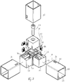
- a corner connector 10 comprising a cube-shaped base body 12 having on a first cube surface 14 a closed surface and two adjacent, mutually and the first cube surface perpendicularly extending second and third closed surfaces 16, 18, while of the second and third cube surface 16, 18 opposite cube surface 20, 22 each have a projection 24, 26 each with a prismatic, in the profile of a substantially rectangular outer cross-section for attaching a tubular profile end 28, 30, see Fig.
- the tube profile end has an inner cross section or inner profile 32 adapted to the outer cross section of the projection 24, 26, the projection 24 being resilient over the alignment line 34 projecting holding elements 36 each projecting into a breakthrough 38 formed near the tubular profile end 28 and bear against the breakthrough edge 40, whereby the tube profile end 28 is axially held on the projection 24 in position, wherein the tube profile end is axially supported on the cube surface.
- the holding element 36 Represents a arranged in a transverse to the tube profile axis 42 channel 44 displaceable against spring force slide, the one end 48 of the carriage 36 in working position due to the spring tension of the spring 46 from the channel 44 with two inclined surfaces 50, 52 resiliently protrudes, wherein the an inclined surface 50 with the thrust direction 58 of the carriage 36 forms a first larger angle 54 as an inlet surface and the second inclined surface 52 corresponding to a smaller angle 56 between the inclined surface 52 and the thrust direction 58 forms the support surface 52, wherein the second inclined surface 52 with the first inclined surface forms approximately a right angle.
- the carriage 36 has a rectangular opening 92, in which the spring 46 can be inserted laterally, wherein a protruding into the opening 92 approach 94 prevents falling out of the spring 46 during assembly.
- the cross section of the channel 44 and the cross section of the carriage 36 guided therein have the basic shape of a rectangle.
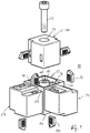
- the area of the spring is drilled out, see for example the right side of the projection 26 in FIG Fig. 1 to support the spring through the shoulder formed by the bore end 60, as shown in FIG Fig. 3B
- the carriage 36 is inserted against the force of the spring 46 by a plug 62 or, in which the plug 62 was inserted into the opening 38 and pushed in the direction of the arrow 58. Since the channel 44 is narrower than the width of the diameter of the spring 36, when drilling for the spring two opposing bottom surfaces, which is now broken by the channel of rectangular cross section and forms the guide for the carriage 36.
- the main body 12 can according to Fig. 1 on its sixth surface 66 a bore 68th having an axial thread to attach a further projection 70 when it has an axial bore 74 to screw by means of a screw 72 the lug 70 on the base body 12, for example, in addition to, for example, two horizontal struts 28, 30 still mount a vertical strut 90, for example to be able to.
- the base body 12 as the lugs 24, 26, 70 is not solid, but as a hollow body with thickening for example horizontal struts 76, 78 provided.
- the pipe section 28 may have a stiffener 76, which is preferably in the region with the opening 38. This increases the stability.
- the projection 24 has at the corresponding point a recess 82, which has the advantage that the inclined surfaces 52, 50 extend far into the cavity 38 without that they reach the surface of the pipe section 28 and interfere. It is advantageous if the lugs 24, 26, 70 each have two holding elements 36 which are arranged for reasons of symmetry with greater strength to each other a maximum distance because of the larger lever arm and also work in opposite directions, such as Fig. 1 makes it clear where the approach 24 has fasteners 36, 136.
- a projection 70 can be screwed with a screw 172 and a cover plate 84 on the sixth side of the body 12, see Fig. 5 , This arrangement is preferable if no third vertical tube profile piece is needed.
- Fig. 8 shows a simplified embodiment of the roof or base frame made of welded together profile pieces 110, wherein the welded frame, here to form a cabinet roof, is provided at its four corners with lugs or receptacles 170, on the perpendicular Eckprofile 190 attachable and by means of slide-shaped holding elements 136 are held in position, which retract into the openings 138 near the profile ends.
- the recordings are held by means of cap screws 172, which is guided through a round hole 111 in the frame and screwed into a threaded bore 168 in the receptacle 170.
- two lugs 98 are projecting on the support surface 113 of the receptacle 170, which penetrate after mounting in bores 115 in the frame 110 and so form a rotation lock.
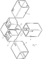
- Fig. 9 shows another embodiment of a frame 210, which consists of four mutually perpendicular sections 117, 119, 121, 123, which are interconnected by flanges 125 having on the bottom receptacles 270 for carriage-shaped holding elements 236, wherein the flanges by means of screws 127th are bolted to the ends of the sections 117, 119, 121 and 123, for which purpose the sections with through-round holes 129 and the flanges can be provided with threaded holes 131.
- the receptacles 270 may also have threaded holes 68 for screwing in a lifting eye 135.
- roof frame 210 is a base frame in which instead of the lifting eyelets adjustable feet can be screwed.
- the frame sections may consist of folded profile sections 117, 119, 121, 123, into which the flanges 125 are fittingly insertable.
- the frame sections can accommodate a roof or base plate after mounting.
- Fig. 8 and 9 It may not just be a designed as a frame floor or roof of a cabinet or housing, but act just as well to a trained as a frame side wall, rear wall or door.
- a consisting of such frames and parts cabinet or housing can be much narrower, in particular much flatter pack than conventional cabinets and housing and thus much easier and cheaper store and ship, the structure is very simple and without special tools is possible, so that the end customer Assembly can be done by yourself.
- the invention can be evaluated commercially in control cabinet construction.
Landscapes
- Mutual Connection Of Rods And Tubes (AREA)
- Furniture Connections (AREA)
Description
Die Erfindung betrifft einen Eckverbinder, umfassend einen ersten, würfelförmigen Grundkörper, der an einer ersten Würfelfläche eine geschlossene Fläche und zwei anschließenden, zueinander und zur ersten Würfelfläche rechtwinklig sich erstreckende zweite und dritte geschlossene Flächen aufweist, während von den der zweiten und dritten Fläche gegenüberliegenden Würfelfläche jeweils ein Ansatz mit prismatischem Außen-Querschnitt zum Aufstecken eines Rohrprofilendes mit an den Außen-Querschnitt des Ansatzes angepassten Innen-Querschnitt ausgeht, wobei der Ansatz über dessen Fluchtlinie federnd vorspringende Halteelemente aufweist, die in einen nahe dem Rohrprofilende gebildeten Durchbruch ragen und sich an den einen Durchbruchrand anlegen, um das Rohrende axial an der Würfelfläche anliegend in Stellung zu halten.The invention relates to a corner connector, comprising a first cube-shaped base body having on a first cube surface a closed surface and two adjoining second and third closed surfaces at right angles to each other and to the first cube surface, while the cube surface is opposite the second and third surfaces in each case an approach with prismatic outer cross-section for attaching a pipe profile end adapted to the outer cross-section of the neck inner cross-section, wherein the approach over its alignment line has resiliently projecting holding elements which protrude into a breakthrough formed near the pipe profile end and to the create a breakthrough edge to hold the tube end axially in place against the cube face.
Ein derartiger Eckverbinder ist aus der
Nachteilig ist jedoch der vielteilige Aufbau, der kompliziert ist und Schrauben erfordert.However, a disadvantage is the multi-part construction, which is complicated and requires screws.
Aufgabe der Erfindung ist es, einen Eckverbinder zu schaffen, der diese Nachteile nicht aufweist und der in einem Rahmengestell, insbesondere zum vereinfachten Aufbau eines Blechschrankes oder Blechgehäuses, angeordnet werden kann.The object of the invention is to provide a corner connector which does not have these disadvantages and which can be arranged in a frame, in particular for the simplified construction of a sheet metal cabinet or sheet metal housing.
Gelöst wird die Aufgabe dadurch, das Halteelement gemäß der
Gemäß einer Weiterbildung reicht der Kanal für den Schlitten durch den Querschnitt des Ansatzes hindurch, wie auch bei der WO-Schrift
Besonders günstig ist eine Weiterbildung, bei der die Federkraft durch eine Spiralfeder gebildet wird, die in einem Durchbruch des Schlittens angeordnet ist und einen die Dicke des Schlittens überragenden Durchmesser aufweist. Wie die WO-Schrift ebenfalls zeigt, Bezugszahl 3526, ist der Kanal im Bereich der Feder aufgebohrt, um die Feder durch die durch das Bohrungsende gebildete Schulter abzustützen.Particularly favorable is a development in which the spring force is formed by a spiral spring, which is arranged in an opening of the carriage and has a thickness of the carriage superior diameter. As the WO document also shows, reference numeral 3526, the channel is drilled in the region of the spring to support the spring by the shoulder formed by the hole end.
Das innere Ende der Bohrung ist gemäß einer noch anderen Weiterbildung im Durchmesser verringert, um das abgestützte Ende der Feder einzuklemmen und so die Feder gegen Herausfallen zu sichern.The inner end of the bore is reduced in diameter according to yet another embodiment to clamp the supported end of the spring and thus to secure the spring against falling out.
Gemäß einer anderen Ausführungsform ist im Bereich des Halteelements oder Snapelements der Querschnitt des Ansatzes um ein solches Maß zurückgesprungen, das der Axialerstreckung der Schrägflächen entspricht, wobei das Rohrende eine entsprechende Verdickung im Querschnitt aufweist.According to another embodiment, in the region of the holding element or Snapelements the cross-section of the neck has jumped back to such a degree that corresponds to the axial extent of the inclined surfaces, wherein the pipe end has a corresponding thickening in cross section.
Gemäß einer noch weiteren Weiterbildung kann eine Würfelfläche des Grundkörpers mit einer axialen Bohrung mit Gewinde versehen sein, um einen weiteren Grundkörper an den ersten Grundkörper mittels einer Schraube anzuschließen, oder an einen vorhandenen Rahmen, wie Grundrahmen oder Dachrahmen eines Gestells oder Schrankes oder Gehäuses.According to yet another development, a cube surface of the main body may be provided with an axial bore threaded to connect a further base body to the first base body by means of a screw, or to an existing frame, such as the base frame or roof frame of a rack or cabinet or housing.
Die Eckverbindung kann mittels eines Steckers wieder gelöst werden, der in den Durchbruch des Rohrprofilendes aufnehmbar ist und solche Ausmaße aufweist, dass der hineinreichenden Teil den Schlitten aus dem Durchbruch herausschieben kann und das Rohrprofilstück vom Ansatz lösen kann.The corner joint can be loosened again by means of a plug which can be received in the opening of the pipe profile end and has such dimensions that the reaching-in part can push the slide out of the opening and detach the pipe profile piece from the socket.
Der würfelförmige Grundkörper und die Ansätze können zur Materialeinsparung Hohlkörper darstellen, mit ggf. Verdickungen und Versteifungsstreben im Inneren des Körpers.The cube-shaped base body and the approaches can be used to save material hollow body, possibly with thickening and stiffening struts inside the body.
Der Eckverbinder kann auch derart gestaltet sein, dass die Ansätze mittels zweier Halteelemente gehalten werden, wobei die Halteelemente sich schräg gegenüberliegend angeordnet sind, wobei die Halteelemente gegenläufig sind.The corner connector can also be designed such that the lugs are held by means of two holding elements, wherein the holding elements are arranged obliquely opposite one another, wherein the holding elements are in opposite directions.
Die Erfindung umfasst auch ein bzw. ist einsetzbar in einem Rahmengestell, insbesondere für einen Blechschrank oder Blechgehäuse, mit einer als Rahmen ausgebildeten Basis und/oder einem als Rahmen ausgebildeten Dach, und/oder eine als Rahmen ausgebildeten Tür, Rückwand oder Seitenwand, wobei der Rahmen rechteckig ist und an seinen vier Ecken Aufnahmen trägt, in denen senkrechte Eckprofile durch Aufstecken aufnehmbar sind und mittels Eckverbinder nach einem der Ansprüche 1 bis 10 gehalten sind.The invention also includes or can be used in a frame, in particular for a sheet metal cabinet or sheet metal housing, with a base formed as a frame and / or designed as a frame roof, and / or designed as a frame door, rear wall or side wall, wherein the Frame is rectangular and carries at its four corners recordings in which vertical corner profiles can be received by plugging and are held by corner connectors according to one of claims 1 to 10.
Gemäß einer Weiterbildung ist der Basis- oder Dachrahmen ein großes, tiefgezogenes Blechteil, oder er ist aus einzelnen, z. B. vier Rahmenteilen bestehenden Teilen zusammengeschweißt, an welchen Rahmen die vier Aufnahmen angeschraubt sind.According to one embodiment, the base or roof frame is a large, deep-drawn sheet metal part, or it is made of individual, z. B. welded together four parts frame parts, to which frame the four shots are screwed.
Gemäß einer anderen Weiterbildung ist das Rahmengestell dadurch gekennzeichnet, dass die vier Aufnahmen mit den schlittenförmigen Halteelementen als Flansche ausgebildet sind, die jeweils um 90 Grad zueinander gedreht angeordnet sind und die durch Schrauben mit den vier Rahmenabschnitten verbunden sind und diese miteinander brückenartig verbinden. Dabei kann der Rahmenabschnitt aus einem gekanteten Profilabschnitt bestehen, in den die Flansche passend einschiebbar sind.According to another embodiment, the frame is characterized in that the four receptacles are formed with the carriage-shaped support members as flanges, which are arranged rotated by 90 degrees to each other and which are connected by screws with the four frame sections and connect them like a bridge. In this case, the frame portion may consist of a folded profile section into which the flanges are fitting inserted.
Gemäß einer anderen Weiterbildung können die Rahmenabschnitte nach Montage eine Dachplatte- oder Bodenplatte oder Tür, Rückwand oder Seitenplatte klemmend aufnehmen.According to another embodiment, the frame sections after mounting a Dachplatten- or bottom plate or door, rear wall or side plate clamped record.
Die Flanschteile können jeweils eine zentrale Gewindebohrung aufweisen, in die eine Kopfschraube, Tragöse oder ein Stellfuß einschraubbar ist, zur Befestigung der Aufnahme an dem Rahmen.The flange parts may each have a central threaded bore into which a cap screw, eyelet or an adjustable foot can be screwed, for fastening the receptacle to the frame.
Gemäß einer noch anderen Ausführungsform des Rahmengestells weisen die Aufnahmen des Rahmens jeweils eine zentrale Gewindebohrung auf, in die eine Kopfschraube, Tragöse oder Stellfuß einschraubbar ist, zur Befestigung der Aufnahme an dem Eckverbinder.According to yet another embodiment of the frame, the receptacles of the frame each have a central threaded bore into which a cap screw, eye or adjustable foot can be screwed, for fastening the receptacle to the corner connector.
Die Erfindung wird anhand von Ausführungsbeispielen näher erläutert, die in den Zeichnungen dargestellt sind.The invention will be explained in more detail with reference to exemplary embodiments, which are illustrated in the drawings.
Es zeigt:
- Fig. 1
- eine auseinandergezogene Darstellung eines erfindungsgemäß aufgebauten Eckverbinders;
- Fig. 2
- den erfindungsgemäßen Eckverbinder in einer perspektivischen auseinandergezogenen Ansicht, zusammen mit zu verbindenden Rohrprofilstücken;
- Fig. 3A und 3B
- Details der Halteelemente und des Steckers zu deren Lösung;
- Fig. 4
- die Lage kurz vor der Montage der Rohrprofilstücke, dargestellt als weitere Ausführungsform des Eckverbinders mit einer Abdeckplatte für den Grundkörper;
- Fig. 5
- die Anordnung der
Fig. 4 , jedoch aus einem anderen perspektivischen Winkel betrachtet; - Fig. 6
- die Anordnung der
Fig. 4 , jedoch perspektivisch aus einem noch anderen Winkel betrachtet; - Fig. 7
- den Eckverbinder nach der Erfindung, jedoch für den Anschluss von drei Rohrprofilstücken;
- Fig. 8
- eine vereinfachte Ausführungsform des Dach- oder Basisrahmens oder eines Tür-, Rückwand- oder Seitenwandrahmens aus miteinander verschweißten Profilstücken zum Aufbau eines Rahmengestells und
- Fig. 9
- eine vereinfachte Ausführungsform des Dach- oder Basisrahmens oder einer Tür-, Rückwand- oder Seitenwandrahmens aus miteinander mittels Brücken bildenden Flanschen verbundenen Profilstücken zum Aufbau eines Rahmengestells mit vier profilierten Streben.
- Fig. 1
- an exploded view of a corner connector constructed according to the invention;
- Fig. 2
- the corner connector according to the invention in a perspective exploded view, together with pipe profile pieces to be joined;
- FIGS. 3A and 3B
- Details of the holding elements and the plug for their solution;
- Fig. 4
- the situation shortly before the assembly of the pipe profile pieces, shown as a further embodiment of the corner connector with a cover plate for the main body;
- Fig. 5
- the arrangement of
Fig. 4 but viewed from another perspective angle; - Fig. 6
- the arrangement of
Fig. 4 but viewed in perspective from yet another angle; - Fig. 7
- the corner connector according to the invention, but for the connection of three pipe profile pieces;
- Fig. 8
- a simplified embodiment of the roof or base frame or a door, rear wall or side wall frame of welded together profile pieces to build a frame and
- Fig. 9
- a simplified embodiment of the roof or base frame or a door, rear wall or side wall frame of interconnected by means of bridges flanges profile pieces to build a frame with four profiled struts.
In
Das Halteelement 36, siehe
Wenn also das Rohrstück 28 über den Ansatz 24 in Richtung der Rohrachse 42 verschoben wird, gelangt zunächst der Rand 86 des Durchmessers 38 auf die zweiten Schrägfläche 52 (Einlauffläche) und schiebt den Schlitten 36 in den Kanal 44 hinein und verbleibt in dieser Stellung,
Die Federkraft 46, die den Schlitten 36 in die in
Der Schlitten 36 besitzt einen Rechteckdurchbruch 92, in den die Feder 46 seitlich eingeschoben werden kann, wobei ein in den Durchbruch 92 ragender Ansatz 94 ein Herausfallen der Feder 46 bei der Montage verhindert.The
Wie aus den Figuren erkennbar ist, hat der Querschnitt des Kanals 44 und der Querschnitt des darin geführten Schlittens 36 die Grundform eines Rechtecks. In dem Bereich, in dem die Feder zu liegen kommt, ist aber der Bereich der Feder aufgebohrt, siehe beispielsweise die rechte Seite des Ansatzes 26 in
In
Bei der in der
Der Grundkörper 12 kann gemäß
Wie die Figuren erkennen lassen, ist der Grundkörper 12 wie die Ansätze 24, 26, 70 nicht massiv, sondern als Hohlkörper mit Verdickungen für die z.B. Horizontalstreben 76, 78 versehen. Auch das Rohrstück 28 kann eine Versteifung 76 aufweisen, die vorzugsweise in dem Bereich mit dem Durchbruch 38 liegt. Dadurch wird die Stabilität erhöht. Der Ansatz 24 weist an der entsprechenden Stelle einen Rücksprung 82 auf, was den Vorteil hat, dass die Schrägflächen 52, 50 in den Hohlraum 38 weit hineinreichen ohne dass sie die Oberfläche des Rohrstücks 28 erreichen und stören würden. Es ist günstig, wenn die Ansatzstücke 24, 26, 70 jeweils zwei Halteelemente 36 aufweisen, die aus Symmetriegründen mit der größeren Festigkeit zueinander eine maximale Distanz wegen des größeren Hebelarms angeordnet sind und auch gegenläufig arbeiten, wie
Statt eines Ansatzes 70 kann mit einer Schraube 172 auch eine Abdeckplatte 84 auf der sechsten Seite des Grundkörpers 12 aufgeschraubt werden, siehe
Die Aufnahmen 270 können ebenfalls Gewindebohrungen 68 zum Einschrauben einer Tragöse 135 aufweisen.The
Dreht man das Ganze um, wird aus dem Dachrahmen 210 ein Basisrahmen, in den statt der Tragösen Verstellfüße eingeschraubt werden können.Turning the whole thing around, from the
Zur Erhöhung der Stabilität der Rahmen 210 können die Rahmenabschnitte aus gekanteten Profilabschnitten 117,119, 121,123 bestehen, in die die Flansche 125 passend einschiebbar sind.To increase the stability of the
Aus dem gleichen Grund ist es günstig, wenn die Rahmenabschnitte nach Montage eine Dach- oder Basisplatte aufnehmen können.For the same reason, it is advantageous if the frame sections can accommodate a roof or base plate after mounting.
Bei den Ausführungsformen der
Ein aus derartigen Rahmen und Einzelteilen bestehender Schrank oder Gehäuse lässt sich viel enger, insbesondere viel flacher verpacken als herkömmliche Schränke und Gehäuse und damit viel einfacher und billiger lagern und versenden, wobei der Aufbau sehr einfach und ohne Spezialwerkzeug möglich ist, so dass der Endkunde die Montage selbst ausführen kann.A consisting of such frames and parts cabinet or housing can be much narrower, in particular much flatter pack than conventional cabinets and housing and thus much easier and cheaper store and ship, the structure is very simple and without special tools is possible, so that the end customer Assembly can be done by yourself.
Die Erfindung ist im Schaltschrankbau gewerblich auswertbar.The invention can be evaluated commercially in control cabinet construction.
- 10, 11010, 110
- Eckverbinder, ProfilstückCorner connector, profile piece
- 1212
- Grundkörperbody
- 1414
- erste geschlossene Flächefirst closed area
- 1616
- zweite geschlossene Flächesecond closed area
- 1818
- dritte geschlossene Flächethird closed area
- 2020
- vierte Flächefourth area
- 2222
- fünfte Fläche des Würfelsfifth surface of the cube
- 2424
- Ansatzapproach
- 2626
- Ansatzapproach
- 2828
- Rohrprofil, EckprofilPipe profile, corner profile
- 3030
- Rohrprofil, EckprofilPipe profile, corner profile
- 3232
- InnenquerschnittInternal cross-section
- 3434
- Fluchtliniealignment
- 3636
- Halteelement, SchlittenRetaining element, slide
- 3838
- Durchbruchbreakthrough
- 4040
- DurchbruchrandBreakthrough edge
- 4242
- Rohrachse, PfeilPipe axis, arrow
- 4444
- Kanalchannel
- 4646
- Federfeather
- 4848
- Schlittenendeshuttle end
- 5050
- Schrägfläche, HalteflächeInclined surface, holding surface
- 5252
- Schrägfläche, EinlaufflächeSloping surface, inlet surface
- 5454
- größerer Winkellarger angle
- 5656
- kleinerer Winkelsmaller angle
- 5858
- Pfeilarrow
- 6060
- angeschnittene Bohrungcut hole
- 6262
- WerkzeugTool
- 6464
- Pfeilarrow
- 6666
- sechste Fläche des Würfelssixth area of the cube
- 68, 16868, 168
- Bohrung mit GewindeBore with thread
- 70, 170, 27070, 170, 270
- Ansatz anschraubbar, AufnahmeBolt-on approach, recording
- 72, 17272, 172
- Kopfschraubehead screw
- 7474
- Axialbohrungaxial bore
- 7676
- Versteifungstiffening
- 7878
- Verdickungthickening
- 8080
- Verdickungthickening
- 8282
- Rücksprungreturn
- 8484
- Platteplate
- 8686
- Randedge
- 8888
- Kanteedge
- 90, 19090, 190
- Vertikalstrebenvertical struts
- 9292
- RechteckdurchbruchRectangular opening
- 9494
- Ansatzapproach
- 9696
- Durchmesser, FederDiameter, spring
- 9898
- Nasenose
- 110110
- Rahmenframe
- 111111
- Bohrungdrilling
- 113113
- Auflageflächebearing surface
- 115115
- Bohrungdrilling
- 117117
- Abschnittesections
- 119119
- Abschnittesections
- 121121
- Abschnittesections
- 123123
- Flanschflange
- 125125
- Schraubescrew
- 127127
- Schraubescrew
- 129129
- Bohrungdrilling
- 131131
- Gewindebohrungthreaded hole
- 135135
- Öseeyelet
Claims (16)
- A corner connector (10), comprising a cubical base body (12) which has, at a first cube face (14), a closed face and, at two connecting extending at right angles to one another and to the first cube face (14), second (16) and a third closed face (18), while there emerges from each of the cube faces opposite the second and third faces a projection with a prismatic external cross-section for mounting a pipe end by an internal cross-section (32) which fits the external cross-section of the projection, wherein the projection has retaining elements (36) which resiliently project over its alignment (34) and which protrude into an opening (38) formed by the pipe end and which rest on one edge (40) of the opening in order to retain the pipe end (28, 30) in position resting axially on the wall surface (20, 21), characterised in that the retaining element (36) a slide (48) displaceable counter to spring force (46) in a channel (44) arranged transverse to the pipe axis (42) in working position due to the spring tension protrudes out of the channel with two angular faces, that one angular face with the thrust direction of the slide (48) forms a first larger angle (54) as a run-in face (52) and the second angular face correspondingly forms a smaller angle (56) as a retaining face (50).
- The corner connector according to Claim 1, characterised in that the channel (44) reaches through the cross-section of the projection (26).
- The corner connector according to Claim 2, characterised in that the spring force (46) is formed by a spiral spring (46) which is arranged in an opening (92) of the slide (36) and which has a diameter (84) which surpasses the thickness of the slide (36).
- The corner connector according to Claim 3, characterised in that the slide is bored out in the region of the spring (60) in order to support the spring (60) by the shoulder formed by the end of the bore.
- The corner connector according to Claim 4, characterised in that the spring (60) is clamped at the inner end of the bore by the reduction (84) in diameter of the bore and is consequently secured against falling out.
- The corner connector according to any one of claims 1 to 5, characterised in that, in the region of the retaining element (36), the cross-section of the projection rebounds_to an extent (82) such that the angular faces (50, 52) are exposed, and such that the pipe cross-section has a corresponding thickening (80).
- The corner connector according to any one of claims 1 to 6, characterised in that a cube face (66) of the base body (12) is equipped with an axial bore (68) having a thread in order to connect a further projection (70) to the base body (12).
- The corner connector according to any one of claims 1 to 7, characterised in that, by means of a plug (62), the part of the slide (36) reaching into the opening (38) of the pipe end can be slid back and the pipe profile part (28) can be released from the projection (24).
- The corner connector according to any one of claims 1 to 8, characterised in that the cube (12) and/or projections (24, 26) are hollow bodies, if necessary with thickenings and reinforcement braces (76, 78).
- The corner connector according to any one of claims 1 to 9, characterised in that the projection (24) has two retaining elements (36, 136) which move in opposite directions and which are situated diagonally opposite one another.
- A rack, in particular for a metal cabinet or metal housing, having a base configured as a frame (110) and/or a roof configured as a frame (110), characterised in that the frame (110) consists of four corner connectors (10, 110, 210) according to any one of claims 1 to 10, which bears projections (170) or receptacles at its four corners, onto which projections (170) or receptacles the perpendicular corner profiles (190) can be mounted.
- The rack according to Claim 11, characterised in that the frame is a large, deep-drawn sheet metal part, or is welded together from individual parts, e.g. the four frame parts or sections (110), onto which frame the four receptacles (170) are screwed.
- The rack according to Claim 11, characterised in that the four receptacles (270) for the retaining elements are flanges (125) which are situated at 90 degrees to one another and which are connected to the four frame sections (117, 110, 121, 123) by means of screws (127) and connect them together.
- The rack according to Claim 13, characterised the frame sections (117, 119, 121, 123) consist of edged profile sections into which the flanges (125) can be fittingly slid.
- The rack according to Claim 14, characterised in that the frame sections (117, 119, 121, 123), after assembly, can clampingly receive a roof panel or floor panel.
- The rack according to any one of Claims 13 to 15, characterised in that the receptacles are flange parts which each have a central threaded bore (68) into which a headed screw, lifting loop (135) or adjustable feet can be screwed.
Applications Claiming Priority (2)
| Application Number | Priority Date | Filing Date | Title |
|---|---|---|---|
| DE201220010584 DE202012010584U1 (en) | 2012-11-07 | 2012-11-07 | Corner connector |
| PCT/EP2013/002678 WO2014072004A1 (en) | 2012-11-07 | 2013-09-06 | Corner connector |
Publications (2)
| Publication Number | Publication Date |
|---|---|
| EP2916687A1 EP2916687A1 (en) | 2015-09-16 |
| EP2916687B1 true EP2916687B1 (en) | 2016-12-07 |
Family
ID=49263290
Family Applications (1)
| Application Number | Title | Priority Date | Filing Date |
|---|---|---|---|
| EP13770635.4A Active EP2916687B1 (en) | 2012-11-07 | 2013-09-06 | Corner connector |
Country Status (3)
| Country | Link |
|---|---|
| EP (1) | EP2916687B1 (en) |
| DE (1) | DE202012010584U1 (en) |
| WO (1) | WO2014072004A1 (en) |
Families Citing this family (3)
| Publication number | Priority date | Publication date | Assignee | Title |
|---|---|---|---|---|
| CN108127272B (en) * | 2018-01-24 | 2024-04-12 | 涿州皓原箔业有限公司 | Laser cutting and punching device for aluminum foil processing |
| CN108302104B (en) * | 2018-02-09 | 2024-04-09 | 宁波积家创意家居设计有限公司 | Expansion buckle for connecting square tubes |
| CN114388958B (en) * | 2022-03-23 | 2022-07-05 | 宁德时代新能源科技股份有限公司 | Battery box, battery and power consumption device |
Family Cites Families (5)
| Publication number | Priority date | Publication date | Assignee | Title |
|---|---|---|---|---|
| US3472539A (en) * | 1969-01-02 | 1969-10-14 | Streater Ind Inc | Tubular frame joint member |
| US4323319A (en) * | 1977-01-17 | 1982-04-06 | Adams Bevoley C | Structural connecting member |
| FR2674581B1 (en) | 1991-03-26 | 1993-06-25 | Legrand Sa | ASSEMBLY DEVICE FOR HOLLOW PROFILES. |
| DE9105664U1 (en) * | 1991-05-07 | 1991-07-04 | Yang, Tian-Show, Tai Ping Hsiang, Taichung | Pipe connection node |
| EP1644904B1 (en) | 2003-06-25 | 2009-12-09 | Universal Electronics Inc. | System and method for monitoring remote control transmissions |
-
2012
- 2012-11-07 DE DE201220010584 patent/DE202012010584U1/en not_active Expired - Lifetime
-
2013
- 2013-09-06 EP EP13770635.4A patent/EP2916687B1/en active Active
- 2013-09-06 WO PCT/EP2013/002678 patent/WO2014072004A1/en active Application Filing
Non-Patent Citations (1)
| Title |
|---|
| None * |
Also Published As
| Publication number | Publication date |
|---|---|
| WO2014072004A1 (en) | 2014-05-15 |
| DE202012010584U1 (en) | 2014-02-12 |
| EP2916687A1 (en) | 2015-09-16 |
Similar Documents
| Publication | Publication Date | Title |
|---|---|---|
| EP3175127B1 (en) | Corner connector for rod-shaped profile elements | |
| DE202017107404U1 (en) | Node connector for profile systems or the like | |
| EP3613931B1 (en) | Assembly of a belt for connecting a leaf with a frame hinged around a hinge axis | |
| DE2460382C2 (en) | Kit with at least one node element | |
| DE202009014463U1 (en) | Safety fence | |
| EP2916687B1 (en) | Corner connector | |
| WO1985004220A1 (en) | Connection element | |
| DE3014507C2 (en) | ||
| EP3406916B1 (en) | Angle connector for loadbearing sections | |
| DE2920320A1 (en) | Housing comprising case with frame - has corner pieces and four front profiles held together by screws that fix front plate | |
| DE102010008697A1 (en) | connection system | |
| DE3147092C2 (en) | Connection system with at least one corner arch element | |
| DE202008016386U1 (en) | connecting device | |
| EP2245318B1 (en) | Connecting junction for profiled elements | |
| DE202012001047U1 (en) | Rack of a cabinet or similar racks | |
| DE9407329U1 (en) | Fastener | |
| DE102014119021A1 (en) | Arrangement for attaching a post made of plastic to a frame strip of a window or a door by means of a post connector | |
| DE202012010397U1 (en) | connecting device | |
| DE29603402U1 (en) | Framework with angle or corner connections of metal profiles, in particular made of light metal | |
| EP0833030B1 (en) | Hinge for doors, windows or similar | |
| EP2453099B1 (en) | Corner joint | |
| DE202012104771U1 (en) | profile connector | |
| DE2738321A1 (en) | CONNECTING COUPLING FOR PIPE PARTS | |
| DE29706040U1 (en) | Corner connector | |
| DE202009003162U1 (en) | Pins for insertion in a mortise |
Legal Events
| Date | Code | Title | Description |
|---|---|---|---|
| PUAI | Public reference made under article 153(3) epc to a published international application that has entered the european phase |
Free format text: ORIGINAL CODE: 0009012 |
|
| 17P | Request for examination filed |
Effective date: 20150417 |
|
| AK | Designated contracting states |
Kind code of ref document: A1 Designated state(s): AL AT BE BG CH CY CZ DE DK EE ES FI FR GB GR HR HU IE IS IT LI LT LU LV MC MK MT NL NO PL PT RO RS SE SI SK SM TR |
|
| AX | Request for extension of the european patent |
Extension state: BA ME |
|
| DAX | Request for extension of the european patent (deleted) | ||
| GRAP | Despatch of communication of intention to grant a patent |
Free format text: ORIGINAL CODE: EPIDOSNIGR1 |
|
| INTG | Intention to grant announced |
Effective date: 20160629 |
|
| GRAJ | Information related to disapproval of communication of intention to grant by the applicant or resumption of examination proceedings by the epo deleted |
Free format text: ORIGINAL CODE: EPIDOSDIGR1 |
|
| GRAR | Information related to intention to grant a patent recorded |
Free format text: ORIGINAL CODE: EPIDOSNIGR71 |
|
| GRAS | Grant fee paid |
Free format text: ORIGINAL CODE: EPIDOSNIGR3 |
|
| GRAA | (expected) grant |
Free format text: ORIGINAL CODE: 0009210 |
|
| INTC | Intention to grant announced (deleted) | ||
| INTG | Intention to grant announced |
Effective date: 20161027 |
|
| AK | Designated contracting states |
Kind code of ref document: B1 Designated state(s): AL AT BE BG CH CY CZ DE DK EE ES FI FR GB GR HR HU IE IS IT LI LT LU LV MC MK MT NL NO PL PT RO RS SE SI SK SM TR |
|
| REG | Reference to a national code |
Ref country code: GB Ref legal event code: FG4D Free format text: NOT ENGLISH |
|
| REG | Reference to a national code |
Ref country code: CH Ref legal event code: EP Ref country code: AT Ref legal event code: REF Ref document number: 850955 Country of ref document: AT Kind code of ref document: T Effective date: 20161215 |
|
| REG | Reference to a national code |
Ref country code: IE Ref legal event code: FG4D Free format text: LANGUAGE OF EP DOCUMENT: GERMAN |
|
| REG | Reference to a national code |
Ref country code: DE Ref legal event code: R096 Ref document number: 502013005670 Country of ref document: DE |
|
| PG25 | Lapsed in a contracting state [announced via postgrant information from national office to epo] |
Ref country code: LV Free format text: LAPSE BECAUSE OF FAILURE TO SUBMIT A TRANSLATION OF THE DESCRIPTION OR TO PAY THE FEE WITHIN THE PRESCRIBED TIME-LIMIT Effective date: 20161207 |
|
| REG | Reference to a national code |
Ref country code: LT Ref legal event code: MG4D |
|
| REG | Reference to a national code |
Ref country code: NL Ref legal event code: MP Effective date: 20161207 |
|
| PG25 | Lapsed in a contracting state [announced via postgrant information from national office to epo] |
Ref country code: SE Free format text: LAPSE BECAUSE OF FAILURE TO SUBMIT A TRANSLATION OF THE DESCRIPTION OR TO PAY THE FEE WITHIN THE PRESCRIBED TIME-LIMIT Effective date: 20161207 Ref country code: NO Free format text: LAPSE BECAUSE OF FAILURE TO SUBMIT A TRANSLATION OF THE DESCRIPTION OR TO PAY THE FEE WITHIN THE PRESCRIBED TIME-LIMIT Effective date: 20170307 Ref country code: GR Free format text: LAPSE BECAUSE OF FAILURE TO SUBMIT A TRANSLATION OF THE DESCRIPTION OR TO PAY THE FEE WITHIN THE PRESCRIBED TIME-LIMIT Effective date: 20170308 Ref country code: LT Free format text: LAPSE BECAUSE OF FAILURE TO SUBMIT A TRANSLATION OF THE DESCRIPTION OR TO PAY THE FEE WITHIN THE PRESCRIBED TIME-LIMIT Effective date: 20161207 |
|
| PG25 | Lapsed in a contracting state [announced via postgrant information from national office to epo] |
Ref country code: ES Free format text: LAPSE BECAUSE OF FAILURE TO SUBMIT A TRANSLATION OF THE DESCRIPTION OR TO PAY THE FEE WITHIN THE PRESCRIBED TIME-LIMIT Effective date: 20161207 Ref country code: FI Free format text: LAPSE BECAUSE OF FAILURE TO SUBMIT A TRANSLATION OF THE DESCRIPTION OR TO PAY THE FEE WITHIN THE PRESCRIBED TIME-LIMIT Effective date: 20161207 Ref country code: RS Free format text: LAPSE BECAUSE OF FAILURE TO SUBMIT A TRANSLATION OF THE DESCRIPTION OR TO PAY THE FEE WITHIN THE PRESCRIBED TIME-LIMIT Effective date: 20161207 Ref country code: HR Free format text: LAPSE BECAUSE OF FAILURE TO SUBMIT A TRANSLATION OF THE DESCRIPTION OR TO PAY THE FEE WITHIN THE PRESCRIBED TIME-LIMIT Effective date: 20161207 |
|
| PG25 | Lapsed in a contracting state [announced via postgrant information from national office to epo] |
Ref country code: NL Free format text: LAPSE BECAUSE OF FAILURE TO SUBMIT A TRANSLATION OF THE DESCRIPTION OR TO PAY THE FEE WITHIN THE PRESCRIBED TIME-LIMIT Effective date: 20161207 |
|
| PG25 | Lapsed in a contracting state [announced via postgrant information from national office to epo] |
Ref country code: EE Free format text: LAPSE BECAUSE OF FAILURE TO SUBMIT A TRANSLATION OF THE DESCRIPTION OR TO PAY THE FEE WITHIN THE PRESCRIBED TIME-LIMIT Effective date: 20161207 Ref country code: IS Free format text: LAPSE BECAUSE OF FAILURE TO SUBMIT A TRANSLATION OF THE DESCRIPTION OR TO PAY THE FEE WITHIN THE PRESCRIBED TIME-LIMIT Effective date: 20170407 Ref country code: RO Free format text: LAPSE BECAUSE OF FAILURE TO SUBMIT A TRANSLATION OF THE DESCRIPTION OR TO PAY THE FEE WITHIN THE PRESCRIBED TIME-LIMIT Effective date: 20161207 Ref country code: SK Free format text: LAPSE BECAUSE OF FAILURE TO SUBMIT A TRANSLATION OF THE DESCRIPTION OR TO PAY THE FEE WITHIN THE PRESCRIBED TIME-LIMIT Effective date: 20161207 Ref country code: CZ Free format text: LAPSE BECAUSE OF FAILURE TO SUBMIT A TRANSLATION OF THE DESCRIPTION OR TO PAY THE FEE WITHIN THE PRESCRIBED TIME-LIMIT Effective date: 20161207 |
|
| PG25 | Lapsed in a contracting state [announced via postgrant information from national office to epo] |
Ref country code: BG Free format text: LAPSE BECAUSE OF FAILURE TO SUBMIT A TRANSLATION OF THE DESCRIPTION OR TO PAY THE FEE WITHIN THE PRESCRIBED TIME-LIMIT Effective date: 20170307 Ref country code: IT Free format text: LAPSE BECAUSE OF FAILURE TO SUBMIT A TRANSLATION OF THE DESCRIPTION OR TO PAY THE FEE WITHIN THE PRESCRIBED TIME-LIMIT Effective date: 20161207 Ref country code: PT Free format text: LAPSE BECAUSE OF FAILURE TO SUBMIT A TRANSLATION OF THE DESCRIPTION OR TO PAY THE FEE WITHIN THE PRESCRIBED TIME-LIMIT Effective date: 20170407 Ref country code: PL Free format text: LAPSE BECAUSE OF FAILURE TO SUBMIT A TRANSLATION OF THE DESCRIPTION OR TO PAY THE FEE WITHIN THE PRESCRIBED TIME-LIMIT Effective date: 20161207 Ref country code: SM Free format text: LAPSE BECAUSE OF FAILURE TO SUBMIT A TRANSLATION OF THE DESCRIPTION OR TO PAY THE FEE WITHIN THE PRESCRIBED TIME-LIMIT Effective date: 20161207 |
|
| REG | Reference to a national code |
Ref country code: DE Ref legal event code: R097 Ref document number: 502013005670 Country of ref document: DE |
|
| PLBE | No opposition filed within time limit |
Free format text: ORIGINAL CODE: 0009261 |
|
| STAA | Information on the status of an ep patent application or granted ep patent |
Free format text: STATUS: NO OPPOSITION FILED WITHIN TIME LIMIT |
|
| 26N | No opposition filed |
Effective date: 20170908 |
|
| PG25 | Lapsed in a contracting state [announced via postgrant information from national office to epo] |
Ref country code: SI Free format text: LAPSE BECAUSE OF FAILURE TO SUBMIT A TRANSLATION OF THE DESCRIPTION OR TO PAY THE FEE WITHIN THE PRESCRIBED TIME-LIMIT Effective date: 20161207 Ref country code: DK Free format text: LAPSE BECAUSE OF FAILURE TO SUBMIT A TRANSLATION OF THE DESCRIPTION OR TO PAY THE FEE WITHIN THE PRESCRIBED TIME-LIMIT Effective date: 20161207 |
|
| REG | Reference to a national code |
Ref country code: CH Ref legal event code: PL |
|
| PG25 | Lapsed in a contracting state [announced via postgrant information from national office to epo] |
Ref country code: MC Free format text: LAPSE BECAUSE OF FAILURE TO SUBMIT A TRANSLATION OF THE DESCRIPTION OR TO PAY THE FEE WITHIN THE PRESCRIBED TIME-LIMIT Effective date: 20161207 |
|
| REG | Reference to a national code |
Ref country code: IE Ref legal event code: MM4A |
|
| REG | Reference to a national code |
Ref country code: BE Ref legal event code: MM Effective date: 20170930 |
|
| PG25 | Lapsed in a contracting state [announced via postgrant information from national office to epo] |
Ref country code: LU Free format text: LAPSE BECAUSE OF NON-PAYMENT OF DUE FEES Effective date: 20170906 |
|
| REG | Reference to a national code |
Ref country code: FR Ref legal event code: ST Effective date: 20180531 |
|
| PG25 | Lapsed in a contracting state [announced via postgrant information from national office to epo] |
Ref country code: CH Free format text: LAPSE BECAUSE OF NON-PAYMENT OF DUE FEES Effective date: 20170930 Ref country code: IE Free format text: LAPSE BECAUSE OF NON-PAYMENT OF DUE FEES Effective date: 20170906 Ref country code: LI Free format text: LAPSE BECAUSE OF NON-PAYMENT OF DUE FEES Effective date: 20170930 |
|
| REG | Reference to a national code |
Ref country code: DE Ref legal event code: R082 Ref document number: 502013005670 Country of ref document: DE Representative=s name: COHAUSZ & FLORACK PATENT- UND RECHTSANWAELTE P, DE |
|
| PG25 | Lapsed in a contracting state [announced via postgrant information from national office to epo] |
Ref country code: FR Free format text: LAPSE BECAUSE OF NON-PAYMENT OF DUE FEES Effective date: 20171002 Ref country code: BE Free format text: LAPSE BECAUSE OF NON-PAYMENT OF DUE FEES Effective date: 20170930 |
|
| PG25 | Lapsed in a contracting state [announced via postgrant information from national office to epo] |
Ref country code: MT Free format text: LAPSE BECAUSE OF FAILURE TO SUBMIT A TRANSLATION OF THE DESCRIPTION OR TO PAY THE FEE WITHIN THE PRESCRIBED TIME-LIMIT Effective date: 20161207 |
|
| PGFP | Annual fee paid to national office [announced via postgrant information from national office to epo] |
Ref country code: GB Payment date: 20180920 Year of fee payment: 6 |
|
| PG25 | Lapsed in a contracting state [announced via postgrant information from national office to epo] |
Ref country code: HU Free format text: LAPSE BECAUSE OF FAILURE TO SUBMIT A TRANSLATION OF THE DESCRIPTION OR TO PAY THE FEE WITHIN THE PRESCRIBED TIME-LIMIT; INVALID AB INITIO Effective date: 20130906 |
|
| PG25 | Lapsed in a contracting state [announced via postgrant information from national office to epo] |
Ref country code: CY Free format text: LAPSE BECAUSE OF FAILURE TO SUBMIT A TRANSLATION OF THE DESCRIPTION OR TO PAY THE FEE WITHIN THE PRESCRIBED TIME-LIMIT Effective date: 20161207 |
|
| REG | Reference to a national code |
Ref country code: AT Ref legal event code: MM01 Ref document number: 850955 Country of ref document: AT Kind code of ref document: T Effective date: 20180906 |
|
| PG25 | Lapsed in a contracting state [announced via postgrant information from national office to epo] |
Ref country code: MK Free format text: LAPSE BECAUSE OF FAILURE TO SUBMIT A TRANSLATION OF THE DESCRIPTION OR TO PAY THE FEE WITHIN THE PRESCRIBED TIME-LIMIT Effective date: 20161207 |
|
| PG25 | Lapsed in a contracting state [announced via postgrant information from national office to epo] |
Ref country code: AT Free format text: LAPSE BECAUSE OF NON-PAYMENT OF DUE FEES Effective date: 20180906 |
|
| PG25 | Lapsed in a contracting state [announced via postgrant information from national office to epo] |
Ref country code: TR Free format text: LAPSE BECAUSE OF FAILURE TO SUBMIT A TRANSLATION OF THE DESCRIPTION OR TO PAY THE FEE WITHIN THE PRESCRIBED TIME-LIMIT Effective date: 20161207 |
|
| PG25 | Lapsed in a contracting state [announced via postgrant information from national office to epo] |
Ref country code: AL Free format text: LAPSE BECAUSE OF FAILURE TO SUBMIT A TRANSLATION OF THE DESCRIPTION OR TO PAY THE FEE WITHIN THE PRESCRIBED TIME-LIMIT Effective date: 20161207 |
|
| GBPC | Gb: european patent ceased through non-payment of renewal fee |
Effective date: 20190906 |
|
| PG25 | Lapsed in a contracting state [announced via postgrant information from national office to epo] |
Ref country code: GB Free format text: LAPSE BECAUSE OF NON-PAYMENT OF DUE FEES Effective date: 20190906 |
|
| REG | Reference to a national code |
Ref country code: DE Ref legal event code: R081 Ref document number: 502013005670 Country of ref document: DE Owner name: DIETER RAMSAUER PATENTVERWERTUNG GMBH & CO. KG, DE Free format text: FORMER OWNER: RAMSAUER, DIETER, 58332 SCHWELM, DE |
|
| P01 | Opt-out of the competence of the unified patent court (upc) registered |
Effective date: 20230628 |
|
| PGFP | Annual fee paid to national office [announced via postgrant information from national office to epo] |
Ref country code: DE Payment date: 20240924 Year of fee payment: 12 |