EP2913181A1 - Noyau rigide et procédé de fabrication de pneus utilisant celui-ci - Google Patents
Noyau rigide et procédé de fabrication de pneus utilisant celui-ci Download PDFInfo
- Publication number
- EP2913181A1 EP2913181A1 EP13843985.6A EP13843985A EP2913181A1 EP 2913181 A1 EP2913181 A1 EP 2913181A1 EP 13843985 A EP13843985 A EP 13843985A EP 2913181 A1 EP2913181 A1 EP 2913181A1
- Authority
- EP
- European Patent Office
- Prior art keywords
- tire
- core
- mold
- radial direction
- rigid core
- Prior art date
- Legal status (The legal status is an assumption and is not a legal conclusion. Google has not performed a legal analysis and makes no representation as to the accuracy of the status listed.)
- Granted
Links
- 238000004519 manufacturing process Methods 0.000 title claims description 13
- 238000000465 moulding Methods 0.000 claims abstract description 52
- 238000007493 shaping process Methods 0.000 claims abstract description 32
- 239000011324 bead Substances 0.000 claims abstract description 31
- 238000000034 method Methods 0.000 claims abstract description 6
- 238000004073 vulcanization Methods 0.000 claims description 12
- 230000003247 decreasing effect Effects 0.000 claims description 5
- 229920001971 elastomer Polymers 0.000 description 12
- 229910000831 Steel Inorganic materials 0.000 description 2
- 125000000484 butyl group Chemical group [H]C([*])([H])C([H])([H])C([H])([H])C([H])([H])[H] 0.000 description 2
- 230000000694 effects Effects 0.000 description 2
- 239000000835 fiber Substances 0.000 description 2
- 239000000463 material Substances 0.000 description 2
- 239000010959 steel Substances 0.000 description 2
- 229920001875 Ebonite Polymers 0.000 description 1
- 239000004760 aramid Substances 0.000 description 1
- 229920003235 aromatic polyamide Polymers 0.000 description 1
- 229920005549 butyl rubber Polymers 0.000 description 1
- 230000007423 decrease Effects 0.000 description 1
- 229920000728 polyester Polymers 0.000 description 1
- 238000005096 rolling process Methods 0.000 description 1
- 238000010998 test method Methods 0.000 description 1
Images


Classifications
-
- B—PERFORMING OPERATIONS; TRANSPORTING
- B29—WORKING OF PLASTICS; WORKING OF SUBSTANCES IN A PLASTIC STATE IN GENERAL
- B29D—PRODUCING PARTICULAR ARTICLES FROM PLASTICS OR FROM SUBSTANCES IN A PLASTIC STATE
- B29D30/00—Producing pneumatic or solid tyres or parts thereof
- B29D30/06—Pneumatic tyres or parts thereof (e.g. produced by casting, moulding, compression moulding, injection moulding, centrifugal casting)
- B29D30/0601—Vulcanising tyres; Vulcanising presses for tyres
- B29D30/0661—Rigid cores therefor, e.g. annular or substantially toroidal cores
-
- B—PERFORMING OPERATIONS; TRANSPORTING
- B29—WORKING OF PLASTICS; WORKING OF SUBSTANCES IN A PLASTIC STATE IN GENERAL
- B29C—SHAPING OR JOINING OF PLASTICS; SHAPING OF MATERIAL IN A PLASTIC STATE, NOT OTHERWISE PROVIDED FOR; AFTER-TREATMENT OF THE SHAPED PRODUCTS, e.g. REPAIRING
- B29C33/00—Moulds or cores; Details thereof or accessories therefor
- B29C33/76—Cores
-
- B—PERFORMING OPERATIONS; TRANSPORTING
- B29—WORKING OF PLASTICS; WORKING OF SUBSTANCES IN A PLASTIC STATE IN GENERAL
- B29D—PRODUCING PARTICULAR ARTICLES FROM PLASTICS OR FROM SUBSTANCES IN A PLASTIC STATE
- B29D30/00—Producing pneumatic or solid tyres or parts thereof
- B29D30/06—Pneumatic tyres or parts thereof (e.g. produced by casting, moulding, compression moulding, injection moulding, centrifugal casting)
- B29D30/0601—Vulcanising tyres; Vulcanising presses for tyres
-
- B—PERFORMING OPERATIONS; TRANSPORTING
- B29—WORKING OF PLASTICS; WORKING OF SUBSTANCES IN A PLASTIC STATE IN GENERAL
- B29D—PRODUCING PARTICULAR ARTICLES FROM PLASTICS OR FROM SUBSTANCES IN A PLASTIC STATE
- B29D30/00—Producing pneumatic or solid tyres or parts thereof
- B29D30/06—Pneumatic tyres or parts thereof (e.g. produced by casting, moulding, compression moulding, injection moulding, centrifugal casting)
- B29D30/08—Building tyres
- B29D30/10—Building tyres on round cores, i.e. the shape of the core is approximately identical with the shape of the completed tyre
- B29D30/12—Cores
-
- B—PERFORMING OPERATIONS; TRANSPORTING
- B29—WORKING OF PLASTICS; WORKING OF SUBSTANCES IN A PLASTIC STATE IN GENERAL
- B29L—INDEXING SCHEME ASSOCIATED WITH SUBCLASS B29C, RELATING TO PARTICULAR ARTICLES
- B29L2030/00—Pneumatic or solid tyres or parts thereof
Definitions
- the present invention relates to a rigid core mold having an outer surface for shaping the inner surface of a pneumatic tire and a method for manufacturing of a pneumatic tire using the same.
- unvulcanized rubber members which become tire constructional members are applied in series on the outer surface of the rigid core mold, and a green tire is shaped.
- the tire constructional members are an inner liner, carcass ply, belt ply, sidewall rubber, tread rubber and the like.
- the green tire is put in a vulcanization mold together with the rigid core mold and vulcanization-molded.
- the rigid core mold is an inner mold.
- the vulcanization mold is outer mold.
- the rigid core mold includes an annular core-mold main portion.
- the core-mold main portion has an outer surface equivalent to the inner surface of the tire.
- the core-mold main portion is sprit in a plurality of core segments. After the vulcanization-molding, each core segment is pulled out inwardly in the tire radial direction from the vulcanized tire in series. Thereby, the rigid core mold is taken out through the bead portion side of the tire (core-mold taking-out step).
- the cross-sectional shape of the inner surface of a pneumatic tire protrudes outwardly in the tire axial direction mostly in the sidewall portions.
- the width of the bead portions is less than the sidewall portions. Accordingly, in order to take out the core segment from the tire, a particularly large force is required to pass through the bead portions.
- the present invention was made with the view to the above-mentioned actual circumstances, and a primary object is to provide a rigid core mold and a method for manufacturing a pneumatic tire in which, essentially by improving the shape of the molding surface of the core-mold main portion, the cycle time of a rigid core-mold taking-out step is reduced.
- An invention according to claim 1 of the present invention is a rigid core mold for manufacturing a pneumatic tire including an annular core-mold main portion having a molding surface for shaping the inner surface of a toroidal pneumatic tire having a tread portion, sidewall portions and bead portions, the core-mold main portion composed of a plurality of core segments arranged in the tire circumferential direction and each taken out from the pneumatic tire by moving inwardly in the tire radial direction, and the molding surface characterized in that, in a meridian section of the core-mold main portion including a tire revolution axis, the ratio Bd/W of a maximum width W in the tire axial direction lying in regions for shaping the sidewall portions, and a width Bd in the tire axial direction measured at toe-end shaping positions for shaping the toe ends of the bead portions is not less than 0.80, an inside zone of the molding surface from the toe-end shaping positions to the position of the maximum width W has a width in the tire axial direction gradually decreasing toward the inside in
- An invention as set forth in claim 2 is the rigid core mold as set forth in claim 1 wherein the molding surface is provided in the inside zone with a maximum inclination position at which the angle ⁇ of the tangent becomes maximum, and a region inside in the tire radial direction from the maximum inclination position includes an inverse arc part formed by an arc having its center outside the core mold.
- An invention as set forth in claim 3 is the rigid core mold as set forth in claim 2 wherein the ratio Hr/h of the length H in the tire radial direction of the inverse arc part and the length h in the tire radial direction of the oblique part is 0.50 to 0.83.
- An invention as set forth in claim 4 is the rigid core mold as set forth in claim 2 or 3 wherein the angle ⁇ of the tangent at the maximum inclination position is 40 to 44 degrees.
- An invention as set forth in claim 5 is the rigid core mold as set forth in any one of claims 1-4, wherein the ratio Bd/W is 0.80 to 0.84.
- An invention as set forth in claim 6 is the rigid core mold as set forth in any one of claims 1-5, wherein the ratio h/H is 0.15 to 0.22.
- An invention as set forth in claim 7 is a method for manufacturing a pneumatic tire utilizing the rigid core mold as set forth in any one of claims 1-6, which is characterized by including a green tire forming step for forming a green tire by applying unvulcanized tire constructional members on an outer surface of the rigid core mold in series, a vulcanization step for putting the green tire in a vulcanization mold together with the rigid core mold and vulcanization-molding it, and a core-mold taking-out step for taking out each core segment from the pneumatic tire after the vulcanization-molding by moving each core segment inwardly in the tire radial direction.
- the molding surface of the core-mold main portion has the ratio Bd/W not less than 0.80, which ratio is of the maximum width W in the tire axial direction lying in the regions for shaping the sidewall portions and the width Bd in the tire axial direction at the toe-end shaping positions for shaping the toe ends of the bead portions.
- a pneumatic tire shaped by the rigid core mold of the present invention is formed such that the width between the toe ends is relatively wide. Accordingly, when the core segment is taken out from the tire, the resistance (frictional force) of the core segment during passing through between the toe ends of the bead portions is reduced.
- the rigid core mold of the present invention is gradually decreased in the width in the tire axial direction toward the inside in the tire radial direction.
- the angle ⁇ of the tangent drawn to the molding surface is not more than 45 degrees with respect to the line in the tire radial direction. Namely, in the core-mold main portion of the present invention, the inclination angle ⁇ of the inside zone with respect to in the tire circumferential direction is small. Therefore, it becomes easy to take out each core segment toward the inside in the tire radial direction.
- the inside zone of the rigid core mold of the present invention includes the oblique part where the angle ⁇ of the tangent becomes 30 to 45 degrees.
- the ratio h/H of the length h in the tire radial direction of the oblique part and the length H in the tire radial direction from the toe-end shaping position to the intersecting point is less than 0.25.
- the intersecting point is the point at which the line in the tire radial direction drawn outwardly in the tire radial direction from the toe-end shaping position intersects with the molding surface.
- the rigid core mold of the present invention which fulfill the above-mentioned configurations reduces the labor to take out the core segments from the tire and consequently shortens the cycle time of the core-mold taking-out step.
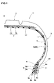
- the rigid core mold in the present embodiment is utilized to manufacture a pneumatic tire 1 such as shown in Figure 1 .
- a passenger radial tire is shown as an example of the pneumatic tire 1.
- the pneumatic tire 1 is toroidal, having a tread portion 2, sidewall portions 3, and bead portions 4.
- the pneumatic tire 1 includes a carcass 6, a belt layer 7 and an inner liner 9.
- the carcass 6 extends from the tread portion 2 to a bead core 5 of the bead portion 4 through the sidewall portion 3.
- the belt layer 7 is disposed on the outside in the tire radial direction of the carcass 6 in the tread portion 2.
- the inner liner 9 is disposed inside the carcass 6.
- the pneumatic tire 1 is formed so that the sidewall portion 3 projects outwardly in the tire axial direction than the bead portion 4.
- the carcass 6 includes a carcass ply 6A.
- the carcass ply 6A is composed of a layer of carcass cords arranged at an angle of 75 to 90 degrees with respect to the tire equator C for example.
- Organic fiber cords, for example, polyester and the like are used as the carcass cords.
- the carcass ply 6A extends between the bead portions 4, 4 in a toroidal form.
- the inner ends 6e in the tire radial direction of the carcass ply 6A terminate in the bead portions 4 without being turned up.
- the bead core 5 is disposed in the bead portion 4.
- the bead core 5 includes an inside core 5A and an outside core 5B.
- the inside core 5A is disposed inside the carcass ply 6A in the tire axial direction.
- the outside core 5B is disposed outside the carcass ply 6A in the tire axial direction.
- the inside core 5A and the outside core 5B are ring-shaped.
- a bead wire 5c made of steel is helically overlap-wound around the tire revolution axis.
- an inner apex rubber 8i is disposed on the inner surface in the tire axial direction of the inside core 5A.
- an outer apex rubber 8o is disposed on the outer surface in the tire axial direction of the outside core 5B.
- the apex rubber 8i, 8o is formed from hard rubber.
- the apex rubber 8i, 8o is formed so as to taper toward the outside in the tire radial direction.
- the belt layer 7 is composed of two inner and outer belt plies 7A, 7B.
- the belt ply 7A, 7B is a layer of belt cords arranged so as to incline at an angle of 10 to 40 degrees with respect to the tire equator C for example.
- the belt cords are superimposed and oriented so as to cross each other.
- Steel cords or organic fiber cords for example aramid and the like are used as the belt cords.
- the inner liner 9 is disposed so as to extend between the toe ends 4e, 4e of the bead portions 4 in a toroidal form.
- the inner liner 9 is disposed over the entire area of the inner surface of the tire 17.
- the inner liner 9 is made of an air-nonpermeable rubber material.
- a butyl based rubber can be suitably used as the air-impermeable rubber material.
- the butyl based rubber contains not less than 60 parts by mass, preferably not less than 80 parts by mass, more preferably 100 parts by mass of butyl rubber (or its derivative) with respect to 100 parts by mass of rubber component.
- the thickness t of the inner liner 9 is for example about 0.5 to 2.0 mm.
- the rigid core mold 10 includes an annular core-mold main portion 11, a core 12 and a pair of side wall bodies 13L, 13U.
- the core-mold main portion 11 has a bore 11h.
- the core 12 is inserted in the bore 11h of the core-mold main portion 11.
- the side wall bodies 13L, 13U are disposed separately from each other in the direction of the axis of the core-mold main portion 11.
- the outer surface of the core-mold main portion 11 forms the molding surface 18.
- the molding surface 18 shapes the inner surface 17 of the pneumatic tire 1. In other words, after the vulcanization-molding, the inner surface 17 of the pneumatic tire 1 in Figure 1 accords with the molding surface 18 of the core-mold main portion 11.
- the core-mold main portion 11 is composed of a plurality of core segments 14 sprit in the tire circumferential direction.
- the core segments 14 include first core segments 14A and second core segments 14B.
- the length L1 in the circumferential direction, of the first core segment 14A gradually decreases toward the inside in the tire radial direction.
- the length L2 in the circumferential direction, of the second core segment 14B gradually increases toward the inside in the tire radial direction.
- the first core segments 14A and the second core segments 14B are alternately arranged in the tire circumferential direction. Thereby, the core-mold main portion 11 becomes an annular body continuous in the tire circumferential direction.
- the molding surface 18 of the core-mold main portion 11 includes a tread molding surface 18a, sidewall molding surfaces 18b, and bead molding surfaces 18c.
- the tread molding surface 18a shapes the inner surface 17 of the tread portion 2 of the pneumatic tire 1 (green tire 1L).
- the sidewall molding surfaces 18b shape the inner surfaces 17 of the sidewall portions 3.
- the bead molding surfaces 18c shape the inner surfaces 17 of the bead portions 4.
- the sidewall molding surfaces 18b are formed so as to project outwardly in the tire axial direction than the bead molding surfaces 18c.
- the sidewall molding surfaces 18b include a maximum width position 20 having a maximum width w in the tire axial direction.
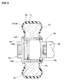
- the core 12 is cylindrical. As shown in Figure 3 , the core 12 is inserted in the bore 11h of the core-mold main portion 11. In the outer circumferential surface of the core 12, there are formed dovetail grooves 19a extending in the direction of the axis of the rigid core mold 10. In the inner circumferential surface of the core segment 14A, 14B, there is formed a dovetail tenon 19b extending in the direction of the axis of the rigid core mold 10. The dovetail grooves 19a and the dovetail tenons 19b are engaged with each other. If the core 12 is inserted in the bore 11h, the first core segments 14A and the second core segment 14B are prevented from moving in the tire radial direction and in the tire circumferential direction.
- one of the side wall bodies 13L is fixed to one side of the core 12 in the direction of the axis with bolts.
- the other side wall body 13U is fixed to the other side in the direction of the axis, of the core 12.
- the other side wall body 13U is fixed to an internal thread portion 15 detachably by being screwed therein.
- the internal thread portion 15 is formed in the bore 11h of the core 12.
- a pair of side wall bodies 13L, 13U prevent the core-mold main portion 11 from moving in the direction of the axis of the core 12.
- each side wall body 13L, 13U is provided with a support shaft part 16 protruding outwardly in the direction of the axis.
- a chuck part 23 is detachably coupled with the support shaft part 16.
- the chuck part 23 is for example, a conveyer (not shown) or the like for conveying the rigid core mold 10 to the vulcanization mold or the like.
- the green tire 1L is put in the vulcanization mold 22 together with the rigid core mold 10.
- the vulcanization mold 22 has a cavity 22s for forming the outer surface of the green tire 1L.
- the green tire 1L is vulcanization-molded so that the outer surface coincides with the cavity 22s, and the inner surface 17 coincides with the molding surface 18 of the core-mold main portion 11.
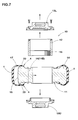
- the vulcanized tire 1 is taken out from the vulcanization mold 22 together with the rigid core mold 10. As shown in Figure 7 , the side wall bodies 13L, 13U and the core 12 are removed from the rigid core mold 10. Thereby, on the inside of the pneumatic tire 1, only the core-mold main portion 11 is remained.
- the first core segments 14A and the second core segments 14B of the core-mold main portion 11 are pulled out inwardly in the tire radial direction in order. Namely, the core-mold main portion 11 is taken out from the inside of the pneumatic tire 1, while being disassembled.
- the molding surface 18 is such that the ratio Bd/W of a maximum width w and a width Bd between the toe ends 4e is not less than 0.80.
- the maximum width W is a maximum width in the tire axial direction which lies in the sidewall molding surfaces 18b.
- the width Bd between the toe ends 4e is the width in the tire axial direction at the toe-end shaping positions 18e for shaping the toe ends 4e of the bead portions.
- the pneumatic tire 1 vulcanization-molded with the core-mold main portion 11 of the present invention is formed such that the width Bd between the toe ends 4e becomes relatively larger.
- the maximum width position 20 of the core segment 14 passes, while increasing the width Bd between the toe ends 4e, 4e.
- the resistance (frictional force) during the maximum width position 20 of the core segment 14 passes through between the toe ends 4e, 4e of the bead portions becomes small by making the vulcanization-molding so that the width Bd between the toe ends 4e is large. Accordingly, it becomes easy to take out the core segments 14 through the bead portion side of the pneumatic tire 1.
- the ratio Bd/w is not less than 0.80, the foregoing effect can be exerted remarkably.
- the ratio Bd/W it becomes easier to take out the core segment 14 from the tire 1.
- the width Bd between the toe ends 4e, 4e is very large, the bead portions need to be largely deformed in order to mount the pneumatic tire 1 on a rim. Therefore, the tire mounting performance deteriorates.
- the ratio Bd/W is preferably not more than 0.84, more preferably not more than 0.83.
- the inside zone 30 is the zone from the toe-end shaping position 18e to the maximum width position 20.
- the width in the tire axial direction of the molding surface 18 of the core-mold main portion 11 is gradually decreased toward the inside in the tire radial direction.
- the angle ⁇ of the tangent T drawn to the molding surface 18 is not more than 45 degrees with respect to a line in the tire radial direction.
- the present invention is intended to reduce the frictional force between the inner surface 17 of the inside zone 30 and the core segment 14 by setting the angle ⁇ as being not more than 45 degrees. Thereby, the taking out of the core segment 14 from the pneumatic tire 1 becomes more easy.
- the inside zone 30 includes an oblique part 32 in which the angle ⁇ of the tangent T is 30 to 45 degrees.
- the oblique part 32 gives a large frictional force to the core segment when taking out the core segment 14. Therefore, it is preferable that the length h in the tire radial direction of the oblique part 32 is limited in a certain range.
- the ratio h/H of the length h in the tire radial direction of the oblique part 32 and the length H in the tire radial direction from the toe-end shaping position 18e to the intersecting point P is less than 0.25. Thereby, the frictional force between the inner surface 17 of the inside zone 30 and the core segment 14 is reduced.
- the ratio h/H is 0.15 to 0.22.
- the intersecting point P is the point at which the line in the tire radial direction drawn outwardly in the tire radial direction from the toe-end shaping position 18e intersects with the molding surface 18.
- the inside zone 30 of the molding surface 18 includes a maximum inclination position 34 at which the angle ⁇ of the tangent T becomes maximum.
- the angle ⁇ of the tangent T is gradually increased from the toe-end shaping position 18e to the maximum inclination position 34 and then gradually decreased from the maximum inclination position 34 to the maximum width position 20.
- the angle ⁇ of the tangent T is not more than 45 degrees.
- the angle ⁇ of the tangent T is preferably 40 to 44 degrees.
- a region 36 inside in the tire radial direction from the maximum inclination position 34 of the molding surface 18 includes an inverse arc part 38 formed by an arc having its center outside the core mold.
- such inverse arc part 38 forms an inverse arc part 40, which is formed by an arc having its center outside the tire, on the carcass ply 6A of the pneumatic tire 1.
- Such inverse arc part 40 of the pneumatic tire 1 forms a large space in the tire cavity as the direction of curvature of the carcass cords is reversed (namely, the inverse arc part 40 changes to the arc having its center within the tire). Thereby, the taking out of each of the core segments of the core-mold main portion 11 becomes easy.
- the ratio Hr/h of the length H in the tire radial direction of the inverse arc part 38 and the length h in the tire radial direction of the oblique part 32 is 0.50 to 0.83.
- Rigid core molds for manufacturing a passenger pneumatic tire of size 235/40R18 having the basic structure of Figure 1 were experimentally manufactured according to the specifications shown in Table 1. The rigid core molds were tested for the performance. Test methods are as follows
Applications Claiming Priority (2)
| Application Number | Priority Date | Filing Date | Title |
|---|---|---|---|
| JP2012221592A JP5952700B2 (ja) | 2012-10-03 | 2012-10-03 | 剛性中子及びそれを用いた空気入りタイヤの製造方法 |
| PCT/JP2013/074738 WO2014054405A1 (fr) | 2012-10-03 | 2013-09-12 | Noyau rigide et procédé de fabrication de pneus utilisant celui-ci |
Publications (3)
| Publication Number | Publication Date |
|---|---|
| EP2913181A1 true EP2913181A1 (fr) | 2015-09-02 |
| EP2913181A4 EP2913181A4 (fr) | 2016-07-27 |
| EP2913181B1 EP2913181B1 (fr) | 2017-11-08 |
Family
ID=50434735
Family Applications (1)
| Application Number | Title | Priority Date | Filing Date |
|---|---|---|---|
| EP13843985.6A Active EP2913181B1 (fr) | 2012-10-03 | 2013-09-12 | Moule à noyau rigide et procédé de fabrication de pneus utilisant celui-ci |
Country Status (5)
| Country | Link |
|---|---|
| US (1) | US10328651B2 (fr) |
| EP (1) | EP2913181B1 (fr) |
| JP (1) | JP5952700B2 (fr) |
| CN (1) | CN104640691B (fr) |
| WO (1) | WO2014054405A1 (fr) |
Cited By (1)
| Publication number | Priority date | Publication date | Assignee | Title |
|---|---|---|---|---|
| CN103386865A (zh) * | 2012-05-07 | 2013-11-13 | 住友橡胶工业株式会社 | 充气轮胎及其制造方法 |
Family Cites Families (19)
| Publication number | Priority date | Publication date | Assignee | Title |
|---|---|---|---|---|
| US1405470A (en) * | 1919-08-29 | 1922-02-07 | Goerge H Wheatley | Method of and apparatus for making resilient tires |
| JPS5326003B2 (fr) * | 1974-11-25 | 1978-07-31 | ||
| US4305446A (en) * | 1977-11-30 | 1981-12-15 | The Goodyear Tire & Rubber Company | Cast tire and method of manufacture |
| US4341251A (en) * | 1981-02-11 | 1982-07-27 | The Firestone Tire & Rubber Company | Tire and method of making |
| JP2554499B2 (ja) * | 1987-07-06 | 1996-11-13 | 住友ゴム工業 株式会社 | 扁平ラジアルタイヤ |
| US6113833A (en) * | 1997-07-22 | 2000-09-05 | Bridgestone Corporation | Segmented toroidal core for manufacturing pneumatic tires |
| JP3845514B2 (ja) * | 1998-05-27 | 2006-11-15 | 横浜ゴム株式会社 | 空気入りタイヤ |
| JP4015280B2 (ja) * | 1998-05-28 | 2007-11-28 | 住友ゴム工業株式会社 | タイヤとリムの組立体 |
| JP2000145790A (ja) | 1998-11-11 | 2000-05-26 | Ntn Corp | 保持器付き針状ころ |
| JP4275476B2 (ja) * | 2003-07-24 | 2009-06-10 | 株式会社ブリヂストン | タイヤ製造用コア |
| JP2005041024A (ja) | 2003-07-24 | 2005-02-17 | Alps Electric Co Ltd | インクリボン |
| JP4552413B2 (ja) * | 2003-10-10 | 2010-09-29 | 凸版印刷株式会社 | アンダーカットを有する広口容器本体及びその無理抜き金型構造 |
| JP2006035900A (ja) * | 2004-07-22 | 2006-02-09 | Nissan Motor Co Ltd | 空気入りタイヤ |
| JP2006082781A (ja) * | 2004-09-17 | 2006-03-30 | Bridgestone Corp | 小型トラック用ラジアルタイヤ及びタイヤ用金型 |
| BRPI0520715B1 (pt) * | 2005-12-19 | 2017-01-24 | Pirelli | método e aparelho para fabricar pneus |
| JP4891727B2 (ja) * | 2006-10-11 | 2012-03-07 | 住友ゴム工業株式会社 | 空気入りタイヤの製造方法 |
| JP4323509B2 (ja) * | 2006-12-01 | 2009-09-02 | 住友ゴム工業株式会社 | タイヤ製造方法 |
| JP5113861B2 (ja) * | 2010-02-15 | 2013-01-09 | 住友ゴム工業株式会社 | 空気入りタイヤの製造方法、及びそれに用いる剛性中子 |
| JP5438545B2 (ja) | 2010-02-19 | 2014-03-12 | 住友ゴム工業株式会社 | 空気入りタイヤの製造方法 |
-
2012
- 2012-10-03 JP JP2012221592A patent/JP5952700B2/ja active Active
-
2013
- 2013-09-12 US US14/427,604 patent/US10328651B2/en active Active
- 2013-09-12 CN CN201380048619.3A patent/CN104640691B/zh active Active
- 2013-09-12 WO PCT/JP2013/074738 patent/WO2014054405A1/fr active Application Filing
- 2013-09-12 EP EP13843985.6A patent/EP2913181B1/fr active Active
Cited By (2)
| Publication number | Priority date | Publication date | Assignee | Title |
|---|---|---|---|---|
| CN103386865A (zh) * | 2012-05-07 | 2013-11-13 | 住友橡胶工业株式会社 | 充气轮胎及其制造方法 |
| CN103386865B (zh) * | 2012-05-07 | 2016-06-22 | 住友橡胶工业株式会社 | 充气轮胎及其制造方法 |
Also Published As
| Publication number | Publication date |
|---|---|
| CN104640691A (zh) | 2015-05-20 |
| JP2014073618A (ja) | 2014-04-24 |
| WO2014054405A1 (fr) | 2014-04-10 |
| JP5952700B2 (ja) | 2016-07-13 |
| US10328651B2 (en) | 2019-06-25 |
| EP2913181B1 (fr) | 2017-11-08 |
| CN104640691B (zh) | 2016-11-02 |
| US20150246492A1 (en) | 2015-09-03 |
| EP2913181A4 (fr) | 2016-07-27 |
Similar Documents
| Publication | Publication Date | Title |
|---|---|---|
| JP5080871B2 (ja) | 空気入りタイヤ、及びその製造方法 | |
| JPH04232035A (ja) | 二輪車用タイヤを製造する方法及びそのタイヤ | |
| JP5302987B2 (ja) | 空気入りタイヤの製造方法 | |
| JP5227392B2 (ja) | 空気入りタイヤ及び空気入りタイヤの製造方法 | |
| EP2923827B1 (fr) | Procédé de fabrication d'un pneu de motocyclette | |
| JP2006043908A (ja) | タイヤ製造方法 | |
| US20130192730A1 (en) | Pneumatic tire and method of manufacturing the same | |
| CN101376321B (zh) | 充气轮胎和轮胎制造方法 | |
| JP5667433B2 (ja) | タイヤ加硫金型及び空気入りタイヤの製造方法 | |
| EP2974891A1 (fr) | Pneumatique | |
| RU2537058C2 (ru) | Способ изготовления пневматической шины | |
| EP2881268A1 (fr) | Pneumatique roulant à plat | |
| US10981417B2 (en) | Pneumatic tire with carcass ply comprising plurality of partly overlapping strip-shaped ply pieces | |
| EP2913181B1 (fr) | Moule à noyau rigide et procédé de fabrication de pneus utilisant celui-ci | |
| EP2326491B1 (fr) | Procédé de construction d'un pneu vert pour roues de véhicule et pneu construit selon ledit procédé | |
| KR101812805B1 (ko) | 공기 타이어 및 그 제조방법 | |
| JP2008093952A (ja) | 空気入りタイヤの製造方法 | |
| CN113002035B (zh) | 轮胎成型鼓和使轮胎成型的方法 | |
| JP5193278B2 (ja) | 空気入りタイヤ | |
| CN109130268B (zh) | 充气轮胎的制造方法、轮胎硫化模具以及充气轮胎 | |
| JP2004249496A (ja) | 空気入りタイヤの製造方法及びその装置 | |
| JP2006044339A (ja) | 空気入りラジアルタイヤ | |
| JP6536204B2 (ja) | 空気入りタイヤの製造方法 | |
| JP2005212278A (ja) | タイヤの製造方法 | |
| JP2017206093A (ja) | 空気入りタイヤ及び剛性中子 |
Legal Events
| Date | Code | Title | Description |
|---|---|---|---|
| PUAI | Public reference made under article 153(3) epc to a published international application that has entered the european phase |
Free format text: ORIGINAL CODE: 0009012 |
|
| 17P | Request for examination filed |
Effective date: 20150420 |
|
| AK | Designated contracting states |
Kind code of ref document: A1 Designated state(s): AL AT BE BG CH CY CZ DE DK EE ES FI FR GB GR HR HU IE IS IT LI LT LU LV MC MK MT NL NO PL PT RO RS SE SI SK SM TR |
|
| AX | Request for extension of the european patent |
Extension state: BA ME |
|
| DAX | Request for extension of the european patent (deleted) | ||
| RA4 | Supplementary search report drawn up and despatched (corrected) |
Effective date: 20160627 |
|
| RIC1 | Information provided on ipc code assigned before grant |
Ipc: B29D 30/12 20060101AFI20160621BHEP Ipc: B29C 33/76 20060101ALI20160621BHEP Ipc: B29L 30/00 20060101ALI20160621BHEP Ipc: B29D 30/06 20060101ALI20160621BHEP |
|
| GRAP | Despatch of communication of intention to grant a patent |
Free format text: ORIGINAL CODE: EPIDOSNIGR1 |
|
| RIN1 | Information on inventor provided before grant (corrected) |
Inventor name: SAKAMOTO, MASAYUKI |
|
| INTG | Intention to grant announced |
Effective date: 20170503 |
|
| GRAS | Grant fee paid |
Free format text: ORIGINAL CODE: EPIDOSNIGR3 |
|
| GRAA | (expected) grant |
Free format text: ORIGINAL CODE: 0009210 |
|
| AK | Designated contracting states |
Kind code of ref document: B1 Designated state(s): AL AT BE BG CH CY CZ DE DK EE ES FI FR GB GR HR HU IE IS IT LI LT LU LV MC MK MT NL NO PL PT RO RS SE SI SK SM TR |
|
| REG | Reference to a national code |
Ref country code: GB Ref legal event code: FG4D |
|
| REG | Reference to a national code |
Ref country code: CH Ref legal event code: EP Ref country code: AT Ref legal event code: REF Ref document number: 943737 Country of ref document: AT Kind code of ref document: T Effective date: 20171115 |
|
| REG | Reference to a national code |
Ref country code: IE Ref legal event code: FG4D |
|
| REG | Reference to a national code |
Ref country code: DE Ref legal event code: R096 Ref document number: 602013029281 Country of ref document: DE |
|
| REG | Reference to a national code |
Ref country code: NL Ref legal event code: MP Effective date: 20171108 |
|
| REG | Reference to a national code |
Ref country code: LT Ref legal event code: MG4D |
|
| REG | Reference to a national code |
Ref country code: AT Ref legal event code: MK05 Ref document number: 943737 Country of ref document: AT Kind code of ref document: T Effective date: 20171108 |
|
| PG25 | Lapsed in a contracting state [announced via postgrant information from national office to epo] |
Ref country code: LT Free format text: LAPSE BECAUSE OF FAILURE TO SUBMIT A TRANSLATION OF THE DESCRIPTION OR TO PAY THE FEE WITHIN THE PRESCRIBED TIME-LIMIT Effective date: 20171108 Ref country code: NL Free format text: LAPSE BECAUSE OF FAILURE TO SUBMIT A TRANSLATION OF THE DESCRIPTION OR TO PAY THE FEE WITHIN THE PRESCRIBED TIME-LIMIT Effective date: 20171108 Ref country code: ES Free format text: LAPSE BECAUSE OF FAILURE TO SUBMIT A TRANSLATION OF THE DESCRIPTION OR TO PAY THE FEE WITHIN THE PRESCRIBED TIME-LIMIT Effective date: 20171108 Ref country code: SE Free format text: LAPSE BECAUSE OF FAILURE TO SUBMIT A TRANSLATION OF THE DESCRIPTION OR TO PAY THE FEE WITHIN THE PRESCRIBED TIME-LIMIT Effective date: 20171108 Ref country code: FI Free format text: LAPSE BECAUSE OF FAILURE TO SUBMIT A TRANSLATION OF THE DESCRIPTION OR TO PAY THE FEE WITHIN THE PRESCRIBED TIME-LIMIT Effective date: 20171108 Ref country code: NO Free format text: LAPSE BECAUSE OF FAILURE TO SUBMIT A TRANSLATION OF THE DESCRIPTION OR TO PAY THE FEE WITHIN THE PRESCRIBED TIME-LIMIT Effective date: 20180208 |
|
| PG25 | Lapsed in a contracting state [announced via postgrant information from national office to epo] |
Ref country code: RS Free format text: LAPSE BECAUSE OF FAILURE TO SUBMIT A TRANSLATION OF THE DESCRIPTION OR TO PAY THE FEE WITHIN THE PRESCRIBED TIME-LIMIT Effective date: 20171108 Ref country code: AT Free format text: LAPSE BECAUSE OF FAILURE TO SUBMIT A TRANSLATION OF THE DESCRIPTION OR TO PAY THE FEE WITHIN THE PRESCRIBED TIME-LIMIT Effective date: 20171108 Ref country code: GR Free format text: LAPSE BECAUSE OF FAILURE TO SUBMIT A TRANSLATION OF THE DESCRIPTION OR TO PAY THE FEE WITHIN THE PRESCRIBED TIME-LIMIT Effective date: 20180209 Ref country code: LV Free format text: LAPSE BECAUSE OF FAILURE TO SUBMIT A TRANSLATION OF THE DESCRIPTION OR TO PAY THE FEE WITHIN THE PRESCRIBED TIME-LIMIT Effective date: 20171108 Ref country code: BG Free format text: LAPSE BECAUSE OF FAILURE TO SUBMIT A TRANSLATION OF THE DESCRIPTION OR TO PAY THE FEE WITHIN THE PRESCRIBED TIME-LIMIT Effective date: 20180208 Ref country code: IS Free format text: LAPSE BECAUSE OF FAILURE TO SUBMIT A TRANSLATION OF THE DESCRIPTION OR TO PAY THE FEE WITHIN THE PRESCRIBED TIME-LIMIT Effective date: 20180308 Ref country code: HR Free format text: LAPSE BECAUSE OF FAILURE TO SUBMIT A TRANSLATION OF THE DESCRIPTION OR TO PAY THE FEE WITHIN THE PRESCRIBED TIME-LIMIT Effective date: 20171108 |
|
| PG25 | Lapsed in a contracting state [announced via postgrant information from national office to epo] |
Ref country code: DK Free format text: LAPSE BECAUSE OF FAILURE TO SUBMIT A TRANSLATION OF THE DESCRIPTION OR TO PAY THE FEE WITHIN THE PRESCRIBED TIME-LIMIT Effective date: 20171108 Ref country code: CY Free format text: LAPSE BECAUSE OF FAILURE TO SUBMIT A TRANSLATION OF THE DESCRIPTION OR TO PAY THE FEE WITHIN THE PRESCRIBED TIME-LIMIT Effective date: 20171108 Ref country code: EE Free format text: LAPSE BECAUSE OF FAILURE TO SUBMIT A TRANSLATION OF THE DESCRIPTION OR TO PAY THE FEE WITHIN THE PRESCRIBED TIME-LIMIT Effective date: 20171108 Ref country code: SK Free format text: LAPSE BECAUSE OF FAILURE TO SUBMIT A TRANSLATION OF THE DESCRIPTION OR TO PAY THE FEE WITHIN THE PRESCRIBED TIME-LIMIT Effective date: 20171108 Ref country code: CZ Free format text: LAPSE BECAUSE OF FAILURE TO SUBMIT A TRANSLATION OF THE DESCRIPTION OR TO PAY THE FEE WITHIN THE PRESCRIBED TIME-LIMIT Effective date: 20171108 |
|
| REG | Reference to a national code |
Ref country code: DE Ref legal event code: R097 Ref document number: 602013029281 Country of ref document: DE |
|
| REG | Reference to a national code |
Ref country code: FR Ref legal event code: PLFP Year of fee payment: 6 |
|
| PG25 | Lapsed in a contracting state [announced via postgrant information from national office to epo] |
Ref country code: IT Free format text: LAPSE BECAUSE OF FAILURE TO SUBMIT A TRANSLATION OF THE DESCRIPTION OR TO PAY THE FEE WITHIN THE PRESCRIBED TIME-LIMIT Effective date: 20171108 Ref country code: SM Free format text: LAPSE BECAUSE OF FAILURE TO SUBMIT A TRANSLATION OF THE DESCRIPTION OR TO PAY THE FEE WITHIN THE PRESCRIBED TIME-LIMIT Effective date: 20171108 Ref country code: RO Free format text: LAPSE BECAUSE OF FAILURE TO SUBMIT A TRANSLATION OF THE DESCRIPTION OR TO PAY THE FEE WITHIN THE PRESCRIBED TIME-LIMIT Effective date: 20171108 Ref country code: PL Free format text: LAPSE BECAUSE OF FAILURE TO SUBMIT A TRANSLATION OF THE DESCRIPTION OR TO PAY THE FEE WITHIN THE PRESCRIBED TIME-LIMIT Effective date: 20171108 |
|
| PLBE | No opposition filed within time limit |
Free format text: ORIGINAL CODE: 0009261 |
|
| STAA | Information on the status of an ep patent application or granted ep patent |
Free format text: STATUS: NO OPPOSITION FILED WITHIN TIME LIMIT |
|
| 26N | No opposition filed |
Effective date: 20180809 |
|
| PG25 | Lapsed in a contracting state [announced via postgrant information from national office to epo] |
Ref country code: SI Free format text: LAPSE BECAUSE OF FAILURE TO SUBMIT A TRANSLATION OF THE DESCRIPTION OR TO PAY THE FEE WITHIN THE PRESCRIBED TIME-LIMIT Effective date: 20171108 |
|
| PG25 | Lapsed in a contracting state [announced via postgrant information from national office to epo] |
Ref country code: MC Free format text: LAPSE BECAUSE OF FAILURE TO SUBMIT A TRANSLATION OF THE DESCRIPTION OR TO PAY THE FEE WITHIN THE PRESCRIBED TIME-LIMIT Effective date: 20171108 |
|
| REG | Reference to a national code |
Ref country code: CH Ref legal event code: PL |
|
| GBPC | Gb: european patent ceased through non-payment of renewal fee |
Effective date: 20180912 |
|
| REG | Reference to a national code |
Ref country code: BE Ref legal event code: MM Effective date: 20180930 |
|
| REG | Reference to a national code |
Ref country code: IE Ref legal event code: MM4A |
|
| PG25 | Lapsed in a contracting state [announced via postgrant information from national office to epo] |
Ref country code: LU Free format text: LAPSE BECAUSE OF NON-PAYMENT OF DUE FEES Effective date: 20180912 |
|
| PG25 | Lapsed in a contracting state [announced via postgrant information from national office to epo] |
Ref country code: IE Free format text: LAPSE BECAUSE OF NON-PAYMENT OF DUE FEES Effective date: 20180912 |
|
| PG25 | Lapsed in a contracting state [announced via postgrant information from national office to epo] |
Ref country code: LI Free format text: LAPSE BECAUSE OF NON-PAYMENT OF DUE FEES Effective date: 20180930 Ref country code: BE Free format text: LAPSE BECAUSE OF NON-PAYMENT OF DUE FEES Effective date: 20180930 Ref country code: CH Free format text: LAPSE BECAUSE OF NON-PAYMENT OF DUE FEES Effective date: 20180930 |
|
| PG25 | Lapsed in a contracting state [announced via postgrant information from national office to epo] |
Ref country code: GB Free format text: LAPSE BECAUSE OF NON-PAYMENT OF DUE FEES Effective date: 20180912 |
|
| PG25 | Lapsed in a contracting state [announced via postgrant information from national office to epo] |
Ref country code: MT Free format text: LAPSE BECAUSE OF NON-PAYMENT OF DUE FEES Effective date: 20180912 |
|
| PG25 | Lapsed in a contracting state [announced via postgrant information from national office to epo] |
Ref country code: TR Free format text: LAPSE BECAUSE OF FAILURE TO SUBMIT A TRANSLATION OF THE DESCRIPTION OR TO PAY THE FEE WITHIN THE PRESCRIBED TIME-LIMIT Effective date: 20171108 |
|
| PG25 | Lapsed in a contracting state [announced via postgrant information from national office to epo] |
Ref country code: PT Free format text: LAPSE BECAUSE OF FAILURE TO SUBMIT A TRANSLATION OF THE DESCRIPTION OR TO PAY THE FEE WITHIN THE PRESCRIBED TIME-LIMIT Effective date: 20171108 |
|
| PG25 | Lapsed in a contracting state [announced via postgrant information from national office to epo] |
Ref country code: HU Free format text: LAPSE BECAUSE OF FAILURE TO SUBMIT A TRANSLATION OF THE DESCRIPTION OR TO PAY THE FEE WITHIN THE PRESCRIBED TIME-LIMIT; INVALID AB INITIO Effective date: 20130912 Ref country code: MK Free format text: LAPSE BECAUSE OF NON-PAYMENT OF DUE FEES Effective date: 20171108 |
|
| PG25 | Lapsed in a contracting state [announced via postgrant information from national office to epo] |
Ref country code: AL Free format text: LAPSE BECAUSE OF FAILURE TO SUBMIT A TRANSLATION OF THE DESCRIPTION OR TO PAY THE FEE WITHIN THE PRESCRIBED TIME-LIMIT Effective date: 20171108 |
|
| PGFP | Annual fee paid to national office [announced via postgrant information from national office to epo] |
Ref country code: FR Payment date: 20230808 Year of fee payment: 11 Ref country code: DE Payment date: 20230802 Year of fee payment: 11 |