EP2911290A2 - Elektrische Drehmaschinensteuerungsvorrichtung und Steuerverfahren für eine elektrische Drehmaschine - Google Patents
Elektrische Drehmaschinensteuerungsvorrichtung und Steuerverfahren für eine elektrische Drehmaschine Download PDFInfo
- Publication number
- EP2911290A2 EP2911290A2 EP14176649.3A EP14176649A EP2911290A2 EP 2911290 A2 EP2911290 A2 EP 2911290A2 EP 14176649 A EP14176649 A EP 14176649A EP 2911290 A2 EP2911290 A2 EP 2911290A2
- Authority
- EP
- European Patent Office
- Prior art keywords
- value
- estimated phase
- electric machine
- phase
- rotary electric
- Prior art date
- Legal status (The legal status is an assumption and is not a legal conclusion. Google has not performed a legal analysis and makes no representation as to the accuracy of the status listed.)
- Withdrawn
Links
Images




Classifications
-
- H—ELECTRICITY
- H02—GENERATION; CONVERSION OR DISTRIBUTION OF ELECTRIC POWER
- H02P—CONTROL OR REGULATION OF ELECTRIC MOTORS, ELECTRIC GENERATORS OR DYNAMO-ELECTRIC CONVERTERS; CONTROLLING TRANSFORMERS, REACTORS OR CHOKE COILS
- H02P6/00—Arrangements for controlling synchronous motors or other dynamo-electric motors using electronic commutation dependent on the rotor position; Electronic commutators therefor
- H02P6/14—Electronic commutators
- H02P6/16—Circuit arrangements for detecting position
- H02P6/18—Circuit arrangements for detecting position without separate position detecting elements
-
- H—ELECTRICITY
- H02—GENERATION; CONVERSION OR DISTRIBUTION OF ELECTRIC POWER
- H02P—CONTROL OR REGULATION OF ELECTRIC MOTORS, ELECTRIC GENERATORS OR DYNAMO-ELECTRIC CONVERTERS; CONTROLLING TRANSFORMERS, REACTORS OR CHOKE COILS
- H02P21/00—Arrangements or methods for the control of electric machines by vector control, e.g. by control of field orientation
- H02P21/24—Vector control not involving the use of rotor position or rotor speed sensors
-
- H—ELECTRICITY
- H02—GENERATION; CONVERSION OR DISTRIBUTION OF ELECTRIC POWER
- H02P—CONTROL OR REGULATION OF ELECTRIC MOTORS, ELECTRIC GENERATORS OR DYNAMO-ELECTRIC CONVERTERS; CONTROLLING TRANSFORMERS, REACTORS OR CHOKE COILS
- H02P6/00—Arrangements for controlling synchronous motors or other dynamo-electric motors using electronic commutation dependent on the rotor position; Electronic commutators therefor
- H02P6/14—Electronic commutators
- H02P6/16—Circuit arrangements for detecting position
- H02P6/18—Circuit arrangements for detecting position without separate position detecting elements
- H02P6/183—Circuit arrangements for detecting position without separate position detecting elements using an injected high frequency signal
-
- H—ELECTRICITY
- H02—GENERATION; CONVERSION OR DISTRIBUTION OF ELECTRIC POWER
- H02P—CONTROL OR REGULATION OF ELECTRIC MOTORS, ELECTRIC GENERATORS OR DYNAMO-ELECTRIC CONVERTERS; CONTROLLING TRANSFORMERS, REACTORS OR CHOKE COILS
- H02P21/00—Arrangements or methods for the control of electric machines by vector control, e.g. by control of field orientation
- H02P21/14—Estimation or adaptation of machine parameters, e.g. flux, current or voltage
- H02P21/18—Estimation of position or speed
-
- H—ELECTRICITY
- H02—GENERATION; CONVERSION OR DISTRIBUTION OF ELECTRIC POWER
- H02P—CONTROL OR REGULATION OF ELECTRIC MOTORS, ELECTRIC GENERATORS OR DYNAMO-ELECTRIC CONVERTERS; CONTROLLING TRANSFORMERS, REACTORS OR CHOKE COILS
- H02P21/00—Arrangements or methods for the control of electric machines by vector control, e.g. by control of field orientation
- H02P21/24—Vector control not involving the use of rotor position or rotor speed sensors
- H02P21/26—Rotor flux based control
-
- H—ELECTRICITY
- H02—GENERATION; CONVERSION OR DISTRIBUTION OF ELECTRIC POWER
- H02P—CONTROL OR REGULATION OF ELECTRIC MOTORS, ELECTRIC GENERATORS OR DYNAMO-ELECTRIC CONVERTERS; CONTROLLING TRANSFORMERS, REACTORS OR CHOKE COILS
- H02P21/00—Arrangements or methods for the control of electric machines by vector control, e.g. by control of field orientation
- H02P21/24—Vector control not involving the use of rotor position or rotor speed sensors
- H02P21/32—Determining the initial rotor position
Definitions
- the present invention relates to a rotary electric machine control apparatus and a control method for a rotary electric machine.
- JP2010-166638 A discloses a control apparatus for a rotary electric machine including control means for estimating a position of a rotor based on rotary electric machine currents flowing through the rotary electric machine detected by current detection means, and outputting a predetermined voltage command to voltage application means based on the estimated position.
- the control means calculates a current command based on a torque command, and calculates a position estimation error based on the current command. Then, the control means corrects the current command based on the position estimation error, and controls the rotary electric machine based on the corrected current command and the estimated position of the rotor.
- the saliency which is a change in inductance depending on the position of the rotor when the current flows through the rotary electric machine, is used for estimating the position of the rotor, and the precision of the estimated position is influenced by a change in inductance characteristics so that a position estimation error is occurred.
- a position estimation error depending on a position of the rotor caused by structures of the motor such as a shape of slots and a distortion of the structure.
- an object of one or more embodiments of the present invention is to provide a rotary electric machine control apparatus and a control method for a rotary electric machine capable of more precise positioning.
- a rotary electric machine control apparatus includes: a phase estimator configured to estimate a first estimated phase value relating to an estimated phase of a rotor based on a rotary electric machine current flowing through a rotary electric machine; a correction value storage configured to store correction information representing a plurality of second estimated phase values and a plurality of correction values relating to the estimated phase in association with each other; a first phase corrector configured to acquire, based on one of the plurality of second estimated phase values corresponding to the first estimated phase value, from the correction information, one of the plurality of correction values associated with the one of the plurality of second estimated phase values, and configured to correct the one of the plurality of second estimated phase values based on the one of the plurality of correction values; a position controller configured to calculate a speed command based on a position command and the corrected second estimated phase value; and a speed controller configured to calculate one of a torque command value and a q-axis current command value based on the speed command and the corrected second
- a control method for a rotary electric machine includes: estimating a first estimated phase value relating to an estimated phase of a rotor based on a rotary electric machine current flowing through a rotary electric machine; acquiring, based on a second estimated phase value corresponding to the first estimated phase value, from correction information storing a plurality of the second estimated phase values and a plurality of correction values in association with each other, one of the plurality of correction values associated with the second estimated phase value, and correcting the second estimated phase value based on the one of the plurality of correction values; calculating a speed command based on a position command and the corrected second estimated phase value; and calculating one of a torque command value and a q-axis current command value based on the speed command and the corrected second estimated phase value.
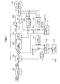
- FIG. 1 is a diagram illustrating an example of an overview of a rotary electric machine control apparatus according to a first embodiment of the present invention.
- a rotary electric machine control apparatus 100 includes, for example, a position controller 101, a speed controller 102, a current command calculator 103, a current controller 104, a first adder 105, a PWM controller 106, a dq converter 108, a phase estimator 109, a phase corrector A 110, a subtractor 111, a phase synchronizer 112, a correction value storage 113, a phase corrector B 114, and a second adder 115.
- the position controller 101 calculates a speed command value representing a command relating to a speed based on, for example, a position command value and an estimated phase value D described later, and outputs the speed command value to the speed controller described later.
- the speed controller 102 calculates a torque command value based on, for example, the speed command value and the estimated phase value D described later.
- the current command calculator 103 calculates a d-axis current command value (Idref) and a q-axis current command value (Iqref) based on the torque command value from the speed controller 102 and a d-axis current command correction value (Idrefc).
- the d-axis current command correction value (Idrefc) is calculated so as to decrease a magnetic field of a rotary electric machine 107 based on voltage command values (Vdref and Vqref) and a maximum voltage which can be output based on a voltage from a voltage source (not shown) when an amplitude value of each of the voltage command values (Vdref and Vqref) reaches the maximum voltage. Details thereof are well-known as disclosed in JP2013-17308 A and the like, and a description thereof is therefore omitted.
- the current controller 104 calculates the d-axis voltage command value (Vdref) and the q-axis voltage command value (Vqref) based on, for example, the q-axis current command value (Iqref), the d-axis current command value (Idref), and current detection values (Id and Iq) in a rotating coordinate system output from the dq converter 108 described later.
- the first adder 105 adds, for example, a high frequency signal to the d-axis voltage command value (Vdref).
- the high frequency signal is a rectangular wave voltage command which changes alternately in a positive direction and in a negative direction at each time period 2Ts in synchronous with an output of a PWM signal described later.
- a voltage amplitude command ⁇ Vh changing alternately in the positive direction and in the negative direction and a phase command ⁇ h (not shown) are output as the high frequency signal at each time period 2Ts.
- Details of the current controller 104 are well-known as disclosed in JP 2010-172080 A and the like, and a description thereof is therefore omitted.
- the PWM controller 106 generates the PWM signal for driving the rotary electric machine 107 based on an estimated phase value C described later, the q-axis voltage command value (Vqref), and the sum of the high frequency signal and the d-axis voltage command value (Vdref) added by the first adder 105.
- the rotary electric machine 107 is controlled by the PWM signal from the PWM controller 106.
- the rotary electric machine 107 corresponds to a sensorless motor requiring no physical sensor for detecting a position of a rotor.
- the dq converter 108 converts rotary electric machine currents (Iu, Iv, and Iw) flowing through the rotary electric machine 107 into the current detection values (Id and Iq) in the rotating coordinate system based on the estimated phase value C described later. Note that, the rotary electric machine currents (Iu, Iv, and Iw) are detected in synchronous with a period of one Nth (N ⁇ 1) of the time period 2Ts.
- the phase estimator 109 estimates an estimated phase value A representing an estimated phase of the rotor of the rotary electric machine 107 based on the rotary electric machine currents (Iu, Iv, and Iw) flowing through the rotary electric machine 107. Specifically, for example, the phase estimator 109 estimates the estimated phase value A by extracting envelopes of current detection values (I ⁇ and I ⁇ ) described later. More specifically, as illustrated in FIG. 2 , the phase estimator 109 includes, for example, a coordinate converter 102, an envelope extractor 202, and a magnetic pole position calculator 203.
- the coordinate converter 201 converts the rotary electric machine currents (Iu, Iv, and Iw) into the current detection values (I ⁇ and I ⁇ ) in a coordinate system at rest, and outputs the current detection values to the envelope extractor 202.
- the envelope extractor 202 includes, for example, a sign discriminator 301, two band-pass filters 302, a gain multiplier 303, two multipliers 304, and two differentiators 305.
- the band-pass filters 302 respectively remove unnecessary components from the current detection values (I ⁇ and I ⁇ ) from the coordinate converter 201.
- the sign discriminator 301 discriminates the sign of the voltage amplitude command, and outputs 1 when the sign is positive and -1 when the sign is negative. The discrimination result is multiplied by a gain by the gain multiplier 303, and is then multiplied by the respective current signals which have passed through the band-pass filters 302.
- the current signal which has passed through the band-pass filter 302 is full-wave rectified on the positive side, and is amplified by the gain multiplier 303.
- the current signals are next respectively differentiated by the differentiators 305, and current values Icos and Isin in two phases, which are envelopes, are output.
- the magnetic pole position calculator 203 calculates the estimated phase value A by means of an arctangent operation applied to the current values Icos and Isin in two phases (tan -1 (Isin/Icos)), for example.
- the phase estimator 109 is well-known, and a detailed description thereof is therefore omitted.
- the above-mentioned configuration of the phase estimator 109 is an example, and other configurations may be employed.
- the phase corrector A 110 outputs a phase correction value A for correcting the estimated phase value A output from the phase estimator 109, for example, when the torque command value output from the speed controller 102 satisfies predetermined criteria.
- the phase correction value A is represented by a first-order function increasing at a predetermined gradient when the torque command value output from the speed controller 102 is equal to or more than a predetermined value (for example, 90%) and equal to or less than a predetermined value (for example, -90%).
- the predetermined values relating to the torque command value are values normalized, with 100% representing a nominal torque of the rotary electric machine 107, for example.
- phase correction value A in FIG. 4 , represented as phase correction value
- the torque command value is equal to or less than the predetermined value
- the phase correction value A in FIG. 4 , represented as phase correction value
- the torque command value is 150%
- the torque command value is equal to or more than the predetermined value
- the phase correction value A is thus approximately 4 (deg(el)).
- the phase corrector A 110 may store the torque command values and the phase correction values A in association with each other as represented by a broken line in FIG. 4 , and may acquire and output the phase correction value A based on the torque command value, and embodiments of the present invention are not limited to the configuration described above. Moreover, the phase corrector A 110 may output the phase correction value A for correcting the estimated phase value A output from the phase estimator 109, for example, when the q-axis current command value (Iqref) output from the speed controller 102 satisfies predetermined criteria.
- Iqref q-axis current command value
- the subtractor 111 subtracts the phase correction value A from the estimated phase value A output from the phase estimator 109.
- the phase synchronizer 112 includes, for example, a feedback circuit including a phase locked loop (PLL) circuit 501 and a first-order lag element 502, and outputs the estimated phase value C corresponding to an estimated phase value B.
- a subtractor 503, the PLL circuit 501, and the first-order lag element 502 are connected in this order, an output from the first-order lag element 502 is subtracted from the estimated phase value B, and a result of the subtraction is input to the PLL circuit 501.
- the phase synchronizer 112 is an example, and is not limited to the configuration described above.
- the correction value storage 113 stores correction information associating a plurality of estimated phase values C and a plurality of correction values with each other. Specifically, for example, the correction value storage 113 stores the plurality of estimated phase values C and the plurality of correction values in association with each other in a form of table.
- the phase corrector B 114 acquires, based on the estimated phase value C from the phase synchronizer 112, the phase correction value B corresponding to the correction value associated with the estimated phase value C from the correction information stored in the correction value storage 113.
- the second adder 115 outputs the estimated phase value D obtained by adding the phase correction value B acquired by the phase corrector B 114 to the estimated phase value C from the phase synchronizer 112.
- the estimated phase value D is input to the position controller 101 and the speed controller 102 as described above.
- the correction value stored in the correction value storage 113 is, for example, determined in advance in correspondence to a difference between the estimated phase value B and a phase value determined based on an actual measurement.
- the rotary electric machine control apparatus 100 capable of more precise positioning and the like is realized. Specifically, for example, a position estimation error based on a change in inductance characteristic caused by a magnitude of a torque command value and the like and a position estimation error depending on the position of the rotor caused by a structure of a motor such as a shape of the slots and a distortion of the structure, which occur in the related art, are prevented.
- the configurations other than the phase corrector A 110, the phase corrector B 114, and the correction value storage 113 namely, the configurations of the position controller 101, the speed controller 102, the current controller 104, the PWM controller 106, the dq converter 108, the phase estimator 109, and the like are well-known as disclosed in JP 2010-172080 A , and a description of detailed configurations and operation is thus omitted.
- the vector controller 109 in the publication corresponds to the current controller 104
- the voltage controller 111 in the publication corresponds to the PWM controller 106.
- the coordinate converter 104, the envelope extractor 105, and the magnetic pole position calculator 106 in the publication respectively correspond to the coordinate converter 201, the envelope extractor 202, and the magnetic pole position calculator 203 included in the phase estimator 109.
- an overview of the operation is described below.
- the result of the addition of the high frequency signal different in frequency from a drive frequency to a magnetic flux component of the voltage command value from the current controller, and a torque component from the current controller are input to the PWM controller, and the PWM controller drives the rotary electric machine 107.
- the coordinate conversion is applied to the currents supplied to the rotary electric machine by using the magnetic pole positions estimated by the dq converter, and currents obtained by removing the same frequency component as the high frequency signal from the converted currents are fed back to the current controller. Then, the current control is carried out so that the deviations from the current command values are 0.
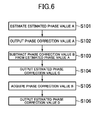
- the phase estimator 109 estimates the estimated phase value A representing the estimated phase of the rotor of the rotary electric machine 107 based on the rotary electric machine currents (Iu, Iv, and Iw) flowing through the rotary electric machine 107 (S101). For example, when the torque command value output from the speed controller 102 satisfies the predetermined criteria, the phase corrector A 110 outputs the phase correction value A for correcting the estimated phase value A output from the phase estimator 109 (S102). The subtractor 111 subtracts the phase correction value A from the estimated phase value A output from the phase estimator 109 (S103). The phase synchronizer 112 outputs the estimated phase value C corresponding to the estimated phase value B obtained by subtracting the phase correction value A from the estimated phase value A (S104).
- the phase corrector B 114 acquires the phase correction value B corresponding to the correction value associated with the estimated phase value C from the correction information stored in the correction value storage 113 based on the estimated phase value C from the phase synchronizer 112 (S105).
- the second adder 115 outputs the estimated phase value D obtained by adding the phase correction value B acquired by the phase corrector B 114 to the estimated phase value C from the phase synchronizer 112 (S106).
- the estimated phase value D is then fed back to the position controller 101 and the speed controller 102, to thereby control, as described above, the rotary electric machine 107 by the position controller 101, the speed controller 102, the current command calculator 103, the current controller 104, the first adder 105, the PWM controller 106, and the like.
- the present invention is not limited to the above-mentioned embodiment, and may be replaced by substantially the same configuration, a configuration which provides the same actions and effects, or a configuration which achieves the same objects as the configuration described in the embodiment.
- specific configurations such as the phase estimator 109 and the phase synchronizer 112 are merely examples, and the configurations are not limited thereto.
- the calculation of the estimated phase value A is not limited to the form in which the high frequency component is superimposed on the d-axis voltage command value (Vdref), thereby extracting the envelopes.
- the calculation may be performed by a method of applying an alternating voltage (or alternating current), and estimating the magnetic pole positions based on a parallel component and an orthogonal component of the rotary electric machine currents corresponding to the alternating voltage, a method of using a carrier wave frequency component of the PWM control, thereby estimating the magnetic pole positions at a low speed including a stop state, and a method of detecting the currents of the motor while changing the applied voltages at each predetermined period of the carrier wave, and acquiring a vector of the current change amounts at the each predetermined period, thereby estimating the magnetic pole positions.
- phase corrector B 114 acquires the phase correction value B from the correction value storage 113 based on the torque command value, and corrects the estimated phase value C. Note that, the same points as those of the first embodiment are not described below.
- FIG. 7 is a diagram illustrating an example of an overview of a power conversion circuit according to a second embodiment of the present invention.
- a rotary electric machine control apparatus 100 includes, as described for the first embodiment, for example, the position controller 101, the speed controller 102, the current controller 104, the first adder 105, the PWM controller 106, the dq converter 108, the phase estimator 109, the phase corrector A 110, the subtractor 111, the phase synchronizer 112, the correction value storage 113, the phase corrector B 114, and the second adder 115.
- the correction value storage 113 further associates and stores the torque command values, different from the first embodiment.
- the correction value storage 113 stores correction information associating the plurality of estimated phase values C, the plurality of correction values, and a plurality of torque command values with one another.
- the correction value storage 113 stores the torque command value, the estimated phase (estimated phase value C), and the correction value representing the phase correction amount in association with one another.
- FIG. 9 shows only a part of the correction information for the sake of simplified illustration. In FIGS. 8 and 9 , and the like, the torque command values are shown, but the q-axis current command values (Iqref) or the like may be used in place of the torque command values as described above.
- the phase corrector B 114 calculates, based on the estimated phase value C from the phase synchronizer 112 and the torque command value from the speed controller 102, the phase correction value B corresponding to the correction value associated with the estimated phase value C from the correction information stored in the correction value storage 113.
- FIG. 9 shows only a part of the correction information for the sake of simplified illustration.
- the correction value when the estimated phase value C is 0 deg(el) and the torque command value is 0% is referred to as data A (-4) ; the correction value when the estimated phase value C is 1 deg(el) and the torque command value is 0%, data B (-3); the correction value when the estimated phase value C is 0 deg(el) and the torque command value is 30%, data C (-3); and the correction value when the estimated phase value C is 1 deg(el) and the torque command value is 30%, data D (-2), and a specific description is now given thereof.
- phase correction value B (represented as the phase correction amount in Expression (3)) is calculated by using the correction information shown in FIG. 9 by means of Expressions (1) to (3).
- X DATA B - DATA A 1 ESTIMATED PHASE - 0.5 ESTIMATED PHASE ⁇ 0.5 ESTIMATED PHASE : INPUT - 0 ESTIMATED PHASE + DATA
- Y ⁇ DATA C - DATA
- phase correction value B phase correction amount
- the phase correction value B may be calculated by other methods.
- the second adder 115 outputs the estimated phase value D obtained by adding the phase correction value B calculated by the phase corrector B 114 to the estimated phase value C from the phase synchronizer 112.
- the phase correction value B is, for example, determined in advance in correspondence to a difference between the estimated phase value B and the phase value determined based on the actual measurement as described for the first embodiment. Moreover, the phase correction value B is stored further in association with each of the torque command values in this embodiment. Thus, the correction corresponding to the torque command value is carried out, and the rotary electric machine control apparatus 100 and the like capable of more precise positioning than that according to the first embodiment is realized.
- the present invention is not limited to the above-mentioned embodiments, and may be replaced by substantially the same configuration, a configuration which provides the same operations and effects, or a configuration which achieves the same objects as the configurations described in the embodiments.
- a description has been given of the case where the estimated phase value D is fed back to the position controller 101 and the speed controller 102, but the estimated phase value D may be fed back only to the position controller 101, for example.
- phase correction value A is calculated in correspondence to the torque command value
- phase correction value B may be calculated in correspondence to the q-axis current command value in place of the torque command value.
- a phase estimator recited in the claims corresponds to the phase estimator 109
- a first phase corrector recited in the claims corresponds to the phase corrector B 114 and the second adder 115.
- a first estimated phase value recited in the claims corresponds to the estimated phase value A
- a second estimated phase value recited in the claims corresponds to the estimated phase value C.
Landscapes
- Engineering & Computer Science (AREA)
- Power Engineering (AREA)
- Control Of Ac Motors In General (AREA)
- Control Of Motors That Do Not Use Commutators (AREA)
Applications Claiming Priority (1)
| Application Number | Priority Date | Filing Date | Title |
|---|---|---|---|
| JP2014034593A JP6003924B2 (ja) | 2014-02-25 | 2014-02-25 | 回転電機制御装置、回転電機の制御方法 |
Publications (2)
| Publication Number | Publication Date |
|---|---|
| EP2911290A2 true EP2911290A2 (de) | 2015-08-26 |
| EP2911290A3 EP2911290A3 (de) | 2016-04-20 |
Family
ID=51162595
Family Applications (1)
| Application Number | Title | Priority Date | Filing Date |
|---|---|---|---|
| EP14176649.3A Withdrawn EP2911290A3 (de) | 2014-02-25 | 2014-07-11 | Elektrische Drehmaschinensteuerungsvorrichtung und Steuerverfahren für eine elektrische Drehmaschine |
Country Status (5)
| Country | Link |
|---|---|
| US (1) | US9397602B2 (de) |
| EP (1) | EP2911290A3 (de) |
| JP (1) | JP6003924B2 (de) |
| KR (1) | KR20150100467A (de) |
| CN (1) | CN104868813A (de) |
Families Citing this family (12)
| Publication number | Priority date | Publication date | Assignee | Title |
|---|---|---|---|---|
| KR20140116728A (ko) * | 2013-03-25 | 2014-10-06 | 엘지전자 주식회사 | 센서리스 bldc 모터의 기동 장치 및 방법 |
| JP5964391B2 (ja) * | 2014-10-31 | 2016-08-03 | ファナック株式会社 | dq三相座標の電流位相を制御するモータ制御装置 |
| JP2016201923A (ja) * | 2015-04-10 | 2016-12-01 | ニデック シンガポール ピーティーイー リミテッド | モータの回転位置推定方法およびモータの制御装置 |
| JP2017197137A (ja) * | 2016-04-28 | 2017-11-02 | 株式会社ジェイテクト | 電動パワーステアリング装置 |
| JP6623987B2 (ja) * | 2016-09-09 | 2019-12-25 | 株式会社デンソー | シフトレンジ制御装置 |
| WO2018173102A1 (ja) * | 2017-03-21 | 2018-09-27 | 三菱電機株式会社 | 磁極位置検出装置及びモータ制御装置 |
| JP7052255B2 (ja) * | 2017-08-25 | 2022-04-12 | コニカミノルタ株式会社 | 画像形成装置 |
| WO2020115859A1 (ja) * | 2018-12-06 | 2020-06-11 | 三菱電機株式会社 | 回転機の制御装置および電動車両の制御装置 |
| CN111327243B (zh) * | 2018-12-13 | 2022-05-27 | 台达电子工业股份有限公司 | 旋转电机控制装置及其控制方法 |
| CN112039401A (zh) * | 2019-05-17 | 2020-12-04 | 杭州三花研究院有限公司 | 一种控制方法和控制装置及其系统 |
| US11192286B2 (en) * | 2019-09-30 | 2021-12-07 | Fanuc Corporation | Phase adjusting device and phase adjusting method |
| JP7241660B2 (ja) * | 2019-10-08 | 2023-03-17 | ルネサスエレクトロニクス株式会社 | レゾルバ補正装置およびレゾルバ補正装置の補正方法 |
Citations (3)
| Publication number | Priority date | Publication date | Assignee | Title |
|---|---|---|---|---|
| JP2010166638A (ja) | 2009-01-13 | 2010-07-29 | Mitsubishi Electric Corp | 回転電機の制御装置 |
| JP2010172080A (ja) | 2009-01-21 | 2010-08-05 | Yaskawa Electric Corp | 交流電動機の制御装置 |
| JP2013017308A (ja) | 2011-07-04 | 2013-01-24 | Yaskawa Electric Corp | インバータ装置および電動機ドライブシステム |
Family Cites Families (16)
| Publication number | Priority date | Publication date | Assignee | Title |
|---|---|---|---|---|
| US6462491B1 (en) | 1999-01-27 | 2002-10-08 | Matsushita Electric Industrial Co., Ltd. | Position sensorless motor control apparatus |
| JP3419725B2 (ja) * | 1999-01-27 | 2003-06-23 | 松下電器産業株式会社 | 位置センサレスモータ制御装置 |
| US6639380B2 (en) | 2000-07-14 | 2003-10-28 | Sul Seung-Ki | Method and system of sensorless field orientation control for an AC motor |
| KR20020007050A (ko) * | 2000-07-14 | 2002-01-26 | 설승기 | 교류 전동기의 자속 기준 제어 방법 및 시스템 |
| US8217605B2 (en) * | 2000-11-10 | 2012-07-10 | Freescale Semiconductor, Inc. | Motor controller for determining a position of a rotor of an AC motor, AC motor system, and method of determining a position of a rotor of an AC motor |
| JP4687846B2 (ja) * | 2001-03-26 | 2011-05-25 | 株式会社安川電機 | 同期電動機の磁極位置推定方法および制御装置 |
| JP4120420B2 (ja) * | 2003-02-20 | 2008-07-16 | 日産自動車株式会社 | モータ制御装置 |
| JP2008505596A (ja) * | 2004-07-01 | 2008-02-21 | インターナショナル レクティファイアー コーポレイション | 永久磁石同期電動機駆動の起動方法およびシステム |
| JP2006109589A (ja) * | 2004-10-04 | 2006-04-20 | Yaskawa Electric Corp | 同期電動機の制御装置 |
| JP4589093B2 (ja) * | 2004-12-10 | 2010-12-01 | 日立オートモティブシステムズ株式会社 | 同期モータ駆動装置及び方法 |
| JP4754379B2 (ja) * | 2006-03-22 | 2011-08-24 | 本田技研工業株式会社 | 電動機の制御装置 |
| EP2191564B1 (de) * | 2007-08-20 | 2015-10-07 | Freescale Semiconductor, Inc. | Motorregler zur bestimmung einer position eines rotors eines wechselstrommotors, wechselstrommotorsystem und verfahren zur bestimmung einer position eines rotors eines wechselstrommotors |
| JP5453729B2 (ja) * | 2008-04-14 | 2014-03-26 | 株式会社ジェイテクト | モータ制御装置および電動パワーステアリング装置 |
| JP5312179B2 (ja) | 2009-04-27 | 2013-10-09 | 本田技研工業株式会社 | Dcブラシレスモータの制御装置 |
| KR101898755B1 (ko) * | 2011-08-18 | 2018-09-13 | 히다찌 겐끼 가부시키가이샤 | 모터 제어 장치 및 그것을 사용한 작업 기계 |
| JP5971707B2 (ja) * | 2011-08-29 | 2016-08-17 | 株式会社東芝 | 同期電動機のセンサレス制御装置ならびにインバータ装置 |
-
2014
- 2014-02-25 JP JP2014034593A patent/JP6003924B2/ja not_active Expired - Fee Related
- 2014-07-11 EP EP14176649.3A patent/EP2911290A3/de not_active Withdrawn
- 2014-08-04 US US14/451,379 patent/US9397602B2/en not_active Expired - Fee Related
- 2014-08-13 CN CN201410397547.XA patent/CN104868813A/zh active Pending
- 2014-08-19 KR KR1020140107555A patent/KR20150100467A/ko not_active Abandoned
Patent Citations (3)
| Publication number | Priority date | Publication date | Assignee | Title |
|---|---|---|---|---|
| JP2010166638A (ja) | 2009-01-13 | 2010-07-29 | Mitsubishi Electric Corp | 回転電機の制御装置 |
| JP2010172080A (ja) | 2009-01-21 | 2010-08-05 | Yaskawa Electric Corp | 交流電動機の制御装置 |
| JP2013017308A (ja) | 2011-07-04 | 2013-01-24 | Yaskawa Electric Corp | インバータ装置および電動機ドライブシステム |
Also Published As
| Publication number | Publication date |
|---|---|
| JP2015159702A (ja) | 2015-09-03 |
| KR20150100467A (ko) | 2015-09-02 |
| EP2911290A3 (de) | 2016-04-20 |
| JP6003924B2 (ja) | 2016-10-05 |
| US20150244298A1 (en) | 2015-08-27 |
| US9397602B2 (en) | 2016-07-19 |
| CN104868813A (zh) | 2015-08-26 |
Similar Documents
| Publication | Publication Date | Title |
|---|---|---|
| US9397602B2 (en) | Rotary electric machine control apparatus and control method for rotary electric machine | |
| JP6367332B2 (ja) | インバータ制御装置及びモータ駆動システム | |
| JP5824918B2 (ja) | インバータ制御装置及びインバータ制御方法 | |
| KR101927693B1 (ko) | 전동기의 센서리스 제어 장치 및 방법 | |
| US9300234B2 (en) | Rotary electric machine controller, rotary electric machine control method, and method of creating control map | |
| EP2690777A2 (de) | Motorsteuervorrichtung | |
| CN113866480B (zh) | 用于马达控制系统的相电流测量中的偏移误差的检测 | |
| US20170264227A1 (en) | Inverter control device and motor drive system | |
| EP2424105A2 (de) | Vektorsteuerungsvorrichtung und Motorsteuersystem | |
| JP5709932B2 (ja) | 同期機制御装置 | |
| JP2012161143A (ja) | 永久磁石同期電動機の制御装置 | |
| WO2014084009A1 (ja) | 電動機の制御装置 | |
| JP5523414B2 (ja) | 交流電動機の制御装置 | |
| JP5278326B2 (ja) | インバータ制御装置及びその制御方法 | |
| JP6519149B2 (ja) | モータ制御装置 | |
| JP5447315B2 (ja) | 交流電動機制御装置 | |
| JP5325556B2 (ja) | モータ制御装置 | |
| JP2006109589A (ja) | 同期電動機の制御装置 | |
| JP4811727B2 (ja) | 永久磁石界磁同期電動機制御装置 | |
| JP6621207B2 (ja) | 電力変換装置 | |
| JP6584371B2 (ja) | モータ制御装置 | |
| JP5983636B2 (ja) | 電動機の制御装置 | |
| JP6880805B2 (ja) | 誘導電動機の制御装置 |
Legal Events
| Date | Code | Title | Description |
|---|---|---|---|
| PUAI | Public reference made under article 153(3) epc to a published international application that has entered the european phase |
Free format text: ORIGINAL CODE: 0009012 |
|
| AK | Designated contracting states |
Kind code of ref document: A2 Designated state(s): AL AT BE BG CH CY CZ DE DK EE ES FI FR GB GR HR HU IE IS IT LI LT LU LV MC MK MT NL NO PL PT RO RS SE SI SK SM TR |
|
| AX | Request for extension of the european patent |
Extension state: BA ME |
|
| PUAL | Search report despatched |
Free format text: ORIGINAL CODE: 0009013 |
|
| AK | Designated contracting states |
Kind code of ref document: A3 Designated state(s): AL AT BE BG CH CY CZ DE DK EE ES FI FR GB GR HR HU IE IS IT LI LT LU LV MC MK MT NL NO PL PT RO RS SE SI SK SM TR |
|
| AX | Request for extension of the european patent |
Extension state: BA ME |
|
| RIC1 | Information provided on ipc code assigned before grant |
Ipc: H02P 21/00 20160101ALI20160314BHEP Ipc: H02P 6/18 20160101AFI20160314BHEP |
|
| STAA | Information on the status of an ep patent application or granted ep patent |
Free format text: STATUS: THE APPLICATION IS DEEMED TO BE WITHDRAWN |
|
| 18D | Application deemed to be withdrawn |
Effective date: 20161021 |