EP2910425B1 - Hornschaltung - Google Patents
Hornschaltung Download PDFInfo
- Publication number
- EP2910425B1 EP2910425B1 EP14000604.0A EP14000604A EP2910425B1 EP 2910425 B1 EP2910425 B1 EP 2910425B1 EP 14000604 A EP14000604 A EP 14000604A EP 2910425 B1 EP2910425 B1 EP 2910425B1
- Authority
- EP
- European Patent Office
- Prior art keywords
- steering wheel
- airbag module
- horn circuit
- contact elements
- horn
- Prior art date
- Legal status (The legal status is an assumption and is not a legal conclusion. Google has not performed a legal analysis and makes no representation as to the accuracy of the status listed.)
- Active
Links
Images


Classifications
-
- B—PERFORMING OPERATIONS; TRANSPORTING
- B60—VEHICLES IN GENERAL
- B60R—VEHICLES, VEHICLE FITTINGS, OR VEHICLE PARTS, NOT OTHERWISE PROVIDED FOR
- B60R21/00—Arrangements or fittings on vehicles for protecting or preventing injuries to occupants or pedestrians in case of accidents or other traffic risks
- B60R21/02—Occupant safety arrangements or fittings, e.g. crash pads
- B60R21/16—Inflatable occupant restraints or confinements designed to inflate upon impact or impending impact, e.g. air bags
- B60R21/20—Arrangements for storing inflatable members in their non-use or deflated condition; Arrangement or mounting of air bag modules or components
- B60R21/203—Arrangements for storing inflatable members in their non-use or deflated condition; Arrangement or mounting of air bag modules or components in steering wheels or steering columns
- B60R21/2035—Arrangements for storing inflatable members in their non-use or deflated condition; Arrangement or mounting of air bag modules or components in steering wheels or steering columns using modules containing inflator, bag and cover attachable to the steering wheel as a complete sub-unit
- B60R21/2037—Arrangements for storing inflatable members in their non-use or deflated condition; Arrangement or mounting of air bag modules or components in steering wheels or steering columns using modules containing inflator, bag and cover attachable to the steering wheel as a complete sub-unit the module or a major component thereof being yieldably mounted, e.g. for actuating the horn switch or for protecting the driver in a non-deployment situation
-
- B—PERFORMING OPERATIONS; TRANSPORTING
- B60—VEHICLES IN GENERAL
- B60Q—ARRANGEMENT OF SIGNALLING OR LIGHTING DEVICES, THE MOUNTING OR SUPPORTING THEREOF OR CIRCUITS THEREFOR, FOR VEHICLES IN GENERAL
- B60Q5/00—Arrangement or adaptation of acoustic signal devices
- B60Q5/001—Switches therefor
- B60Q5/003—Switches therefor mounted on the steering wheel
Definitions
- the present invention relates to a horn circuit according to the preamble of claim 1.
- Horn circuits for vehicles are generally known in the art. They are used to produce a warning signal for road safety reasons. In the majority of modern vehicles, the horn circuit is integrated together with an airbag module in the steering wheel of the automotive vehicle. Fixing arrangements for attaching the airbag module to a steering wheel are for example described in EP 2 213 523 A1 and EP 2 145 801 A1 .
- Conventional horn circuits comprise at least two contact elements, which when electrically contact with each other produce a horn signal. The horn circuit is usually arranged such that one contact element is fixed, while the other contact element is moveable so as to touch the fixed contact element. Moving the contact element and thereby touching the other contact element will close the horn circuit and an audible warning signal will be produced by means of an appropriate sound generator.
- conventional horn circuits require a large space to accommodate the two contact elements and to provide a sufficient distance between them.
- the space requirements of conventional horn circuits form a severe problem in light of the present trend of miniaturisation, especially in the automotive industry. This is particularly true, if not only the horn circuit but also an airbag module is to be integrated in the steering wheel of a vehicle.
- a horn circuit of the above kind is known, for example, from US 2012/0080868 A1 . It requires a multitude of movably and fixedly arranged parts, which need to interact in small tolerances and thereby result high cost and assembly effort.
- the present invention provides a horn circuit comprising the features of claim 1.
- the horn circuit serves for activating a horn of a vehicle, which is adapted to be integrated in an airbag module of the vehicle or in an attachment member for connecting the airbag module to the steering wheel.
- the attachment member may form an integral part of the steering wheel or may be formed as a separate element, which is (releasably) connected to the steering wheel for connecting the airbag module to the steering wheel.
- the horn circuit comprises at least two contact elements, wherein a horn signal is produced when the at least two contact elements electrically contact with each other.
- the horn circuit according to the present invention is characterised in that the at least two contact elements are adapted to electrically connect with each other by means of at least one conductive spring element for fixing an airbag module to a steering wheel.
- the invention provides a horn circuit for activating a horn of a vehicle, which is adapted to be attached to one of: an airbag module for a vehicle, an attachment member for connecting the airbag module to a steering wheel, and the steering wheel, the horn circuit comprising at least two contact elements, wherein a horn signal is produced when the at least two contact elements get in direct or indirect electrical contact; therein the at least two contact elements are arranged adjacent to each other and form a compact entity.
- the structural complexity of the airbag module and the steering wheel can be greatly reduced, and assembly of all components forming the airbag module and the steering wheel can be simplified.
- the same horn circuit may be utilized in different designs of airbag modules and the steering wheels, being adapted specifically to the varying needs of different vehicles, without need of adaptation of the horn circuit, such that a more economical manufacturing is achieved.
- the at least two contact elements are arranged adjacent to one another and/ or situated substantially above each other in a horn activating direction.
- they are bound to one another by a cage formed from synthetic material.
- the cage has a substantially similar shape, in particular a ring-shape, as the contact elements do.
- the horn circuit comprises at least one conductive spring element which is configured to fix the airbag module to a steering wheel and to act as a contact closing member for electrically connecting the two contact elements upon activating the horn of a vehicle.
- the horn circuit fits into available unused room of the steering wheel, which is usually present between an airbag module and an attachment member for connecting the airbag module to a steering wheel.
- the horn circuit according to the present invention can therefore easily be integrated in an existing steering wheel airbag module, without requiring additional space.
- An electrical connection between the at least two contact elements of the horn circuit can be realised by a conductive spring element, which is present in the vehicle for attaching the airbag module to the steering wheel.
- existing elements may be used for realising an electrical connection between the at least two contact elements.
- the horn circuit is activated by moving the complete horn circuit unit relative to an attachment member of a vehicle in a steering wheel system.
- the electrical connection between the at least two contact elements of the horn circuit is not performed by moving the two contact elements relative to each other but by either moving the two contact elements simultaneously relative to a third part, or by moving a third part (conductive spring element) relative to the two fixed contact elements.
- the present invention does not only provide for a horn circuit which is easy to implement and less expensive to manufacture, but in addition to a horn circuit which can be integrated in existing space without the need for providing an extra space.
- the electrical connection between the two contact elements is established by means of an existing means for connecting the airbag module to the steering wheel, namely by means of the spring element, no additional device or element is required for closing the horn circuit.
- the at least two contact elements are arranged adjacent to each other and form a compact entity. This is possible because the at least two contact elements do not require a relative movement to each other. Furthermore, the two contact elements are substantially flat and electrically isolated from each other. Owing to this configuration, the electrical contact between the two contact elements will only establish, if the at least two contact elements are electrically connected to each other by touching the at least one conductive spring element.
- the at least two contact elements are formed as wires or plates. Owing to this substantially flat configuration, the horn circuit can easily be integrated in existing space of the airbag module or an attachment member for connecting the airbag module to a steering wheel. More specifically, each of the at least two contact elements may substantially have an identical form, which is preferably ring-shaped, wherein the two substantially identical (ring-)shaped contact elements are arranged in parallel to each other. Owing to this parallel and preferably neighbouring configuration of the two contact elements, the two contact elements can be arranged in a space saving manner.
- the isolative material is at least partially arranged between the two contact elements and forms an intermediate layer electrically separating the two elements.
- each of the two contact elements preferably comprises at least one latch.
- the latches of the at least two contact elements may be arranged pairwise in a (small) distance from each other. More specifically, the distance between the latches should be smaller than the length of the conductive spring element, such that an electrical connection can be established between the two contact elements when touching the conductive spring element.
- the at least two contact elements may at least partially be surrounded by a housing.
- the housing is adapted to be positioned in a bottom portion of an airbag module and to be attached thereto.
- the housing may be adapted to be positioned in an upper portion of an attachment member for connecting the airbag module to the steering wheel.
- a preferred embodiment of the present invention also provides an airbag module for the attachment to a steering wheel or an attachment member for attaching the airbag module to the steering wheel, wherein the airbag module further comprises an integrated horn circuit which is attached to the to the airbag module and adapted to be activated by at least one conductive spring element, located at one of: the airbag module, the steering wheel, and the attachment member, the horn circuit being configured according to at least one of embodiments described above.
- a further preferred embodiment of the present invention also provides a steering wheel system comprising at least one conductive spring element for the attachment of an airbag module and/or an attachment member for attaching the airbag module to the steering wheel, wherein the steering wheel system further comprises an integrated horn circuit which is attached to the to the steering wheel and adapted to be activated by the at least one conductive spring element, the horn circuit being configured according to at least one of the embodiments described above.
- the horn circuit is arranged between the airbag module and the attachment member in the assembled state of the steering wheel system.
- the horn circuit may be attached to a bottom portion of the airbag module facing the attachment member in an assembled state of the steering wheel system.
- the horn circuit may also be attached to an upper portion of the attachment member facing the airbag module in an assembled state of the steering wheel system.
- the horn circuit is attached to a bottom portion of the steering wheel's receiving opening for the airbag module facing the attachment member or the airbag module in an assembled state of the steering wheel system.
- the at least one conductive spring element may be attached to the airbag module or alternatively to the attachment member.
- the at least one conductive spring element is preferably adapted to cooperate with a hook element, which is connected to the respective other part of the airbag module or the attachment member. That is, if the conductive spring element is attached to the airbag module, the hook element is attached to the attachment member and if the conductive spring element is attached to the attachment member, the hook element is associated with the airbag module.
- a further preferred embodiment of the present invention also provides for a vehicle, in particular an automotive vehicle, which comprises a horn circuit according to the present invention or which comprises a steering wheel system according to the present invention.
- Fig. 1 shows a schematic cross-sectional view of a steering wheel system 1 according to the present invention.
- the steering wheel system 1 comprises an airbag module 3 and an attachment member 5 for connecting the airbag module to a steering wheel (not illustrated)
- the attachment member 5 is in the present example formed as a separate element, which is connectable to a steering wheel.
- the attachment member 5 may form an integral part of the steering wheel, for example of the metal skeleton, which is a more compact solution.
- the attachment member 5 comprises two parallel bridges 7 and 7' for holding a releasable spring element 9, which extends through the bridges 7 and 7'.
- the spring element 9 serves for retaining a hook element 11, which can best be seen in Fig. 7 .
- the hook element 11 is attached to a bottom portion 13 of the airbag module 3 at a radially outer portion thereof, wherein the bottom portion 13 of the airbag module 3 faces the attachment member 5 in the assembled state of the steering wheel system 1.
- the hook element 11 may be a snap-fitting or clip-in-hook, which must be engaged with the spring element 9 in order to fix the airbag module to a steering wheel.
- a horn circuit 15 is arranged at the lower portion 13 of the airbag module 3.
- the horn circuit 15 comprises a conductive material and comprises a first contact element 17 and a second contact element 19.
- the first and second contact elements 17 and 19 are substantially formed as flat and ring-shaped plates, which are arranged in parallel and adjacent to each other.
- an isolative material is provided between the first and second contact elements 17 and 19.
- Each of the first and second contact elements 17 and 19 comprises in the present embodiment three latches 21a-21c and 23a-23c, respectively, for contacting a respective spring element 9, which is made from a conductive material.
- the first and second contact elements 17 and 19 have a substantially identical size and shape and are slightly offset to each other in a circumferential direction such that a latch 21a-21c of the first contact element 17 and a latch 23a-23c of a second contact element are arranged pairwise and adjacent to each other.
- the distance between two latches forming a pair should be such that there is no electrical contact between them or the first and second contact elements and such that the distance is smaller than the length I of a conductive spring element 9.
- each pair of latches 21a/23a, 21b/23b and 21c/23c is associated with a dedicated conductive spring element 9. That is, the steering wheel system 1 according to claim 1 comprises three spring elements 9, which have a double function. Firstly, they fix the airbag module 3 to the steering wheel via the attachment member 5 and secondly, they are used for providing an electrical connection between the first and second contact elements 17 and 19, when the horn circuit is activated manually by pressing the airbag module 3 in a downward direction d towards the attachment member 5.
- the Horn circuit may comprise connection elements 25 and 27 to connect the horn circuit to electric cables coming from the vehicle side.
- Further resilient distance elements 12a-c are provided between the airbag module 3 and the steering wheel (or the adapter plate 5) for urging or biasing the airbag module 3 in the resting position opposite to the downward direction d and to separate elements 21,23 and 9 when horn activation is not required.
- the horn circuit 15 is arranged at the bottom portions 13 of the airbag module 3 and the latches 21, 23 are aligned with the spring elements 9.
- the circumferential position of the latches substantially corresponds to the circumferential position of the spring elements and the hook elements.
- Figs. 3 to 5 are perspective views of a circular shaped attachment member 5, which in the present case is formed as a separate part of the steering wheel.
- Fig. 4 shows the substantially U-shaped spring elements, which have two substantially parallel arms 33 and 33' for engaging the hook element 11.
- the spring element 9 is at least partially made from a conductive material and the arms 33, 33' are preferably resilient such that a hook element 11 (not illustrated) can be retained in an opening 15, wherein the opening 15 is arranged between and below the bridges 7, 7' in the attachment member 5 (see Fig. 3 and 5 ).
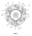
- Fig. 6 is a bottom view of a steering wheel system 1 according to the present invention, wherein the attachment member 5 is omitted for reasons of clarity except for the spring element 9.
- the horn circuit 15 is concentrically arranged on the bottom portion 13 of the airbag module 3, which has a round cross-sectional shape.
- the pairs of latches attached to the first and second contact elements 17 and 19 are symmetrically arranged such that the position of the latches coincides with the position of the spring elements 9 and the hook elements 11 in the assembled state of the steering wheel system 1.
- Fig. 7 is a detailed view of the steering wheel system 1. As can be seen, the hook element 11 is engaged by the spring element 9 and thereby fixes the airbag module 3 to the attachment member 5 (not illustrated). Fig. 7 further shows that in the normal, i.e. non-activated state of the horn circuit 15, the latches 21a-21c and 23a-23c are provided in a distance x from the upper surface of the spring elements 9. In the event that a compressive force is applied on the airbag module 3 in the downward direction d, the horn circuit 15 and thereby the latches 21, 23 are moved in the direction towards the spring element 9. During movement of the horn circuit 15, i.e.
- the latches 21 and 23 of the first and second contact elements 17 and 19 are arranged in a same plane or in other words on a same height level in the downward direction d such that the pairwise arranged latches contact the associated spring element 9 at the same time and thus establishing an electrical connection between the first and second contact elements 17 and 19.
- the horn circuit 15 is closed and a horn signal is produced in order to warn pedestrians or other vehicle drivers.
- the horn circuit 15 and thus the first and second contact elements 17 and 19 are preferably arranged in a housing 29, which at least partially surrounds the contact element 17, 19.
- the housing 29 has preferably a similar shape than the first and second contact elements 17, 19 and is constructed such that the latches are arranged in radially extending hollow arms 31a-31c.
- the ring-shaped main body of the contact element 17, 19 is completely embedded in the housing 29, whereas electrical connection endings 25, 27 as well as the latches 21, 23 of the contact element 17, 19 are exposed and thus are not fully surrounded by the housing 29, such that they can get in touching contact with the spring elements 9 and the attachment member 5, respectively.
- the horn circuit 15 may also be attached to the attachment member 5. This is particularly the case, if the hook members 11 are located on the attachment member 5 and the bridges 7, 7', the openings 35 and the spring elements 9 are attached to the airbag module 3. In this case, the horn circuit unit 15 will be fixedly installed, while the spring elements 9 will move together with the airbag module 3 in order to touch the latches 21, 23 and to thereby close the horn circuit.
- the present invention is not restricted to a horn circuit 15, which is attached to the airbag module 3. Rather, the horn circuit 15 may be alternatively arranged on the attachment member 5, which may form an integral or a separate part of the steering wheel.
- the size and shape of the horn circuit 15 may vary depending on the available space between the airbag module and the attachment member, and depending on the shape and size of the airbag module and the attachment member, respectively. Furthermore, different sizes and shapes of the spring element may necessitate an appropriate modification of the horn circuit design.
- the present invention provides for an advantageous space saving horn circuit, which does not need any extra space or additional devices, but which can easily be placed in existing space between the airbag module 3 and the attachment member 5 and which can be activated by existing elements of the steering wheel unit.
Claims (15)
- Hupenschaltkreis (15) zur Betätigung einer Fahrzeughupe befestigbar an einem der folgenden Teile: einem Gassackmodul (3) für ein Fahrzeug, einem Befestigungselement (5) zur Verbindung des Gassackmoduls (3) mit einem Lenkrad und dem Lenkrad, wobei der Hupenschaltkreis (15) mindestens zwei Kontaktelemente (17, 19) umfasst, wobei ein Hupensignal erzeugt wird, wenn die mindestens zwei Kontaktelemente in direkten oder indirekten elektrischen Kontakt kommen, wobei
die mindestens zwei Kontaktelemente (17, 19) benachbart zueinander angeordnet sind und eine kompakte Einheit bilden, und weiterhin mindestens ein leitfähiges Federelement (9) enthält, das zur Befestigung des Gassackmoduls (3) am Lenkrad ausgebildet ist,
dadurch gekennzeichnet, dass
das mindestens eine leitfähige Federelement (9) derart ausgebildet ist, dass es als ein Kontaktschließelement zur elektrischen Verbindung der zwei Kontaktelemente (17, 19) bei Betätigung der Fahrzeughupe dient. - Hupenschaltkreis nach Anspruch 1,
dadurch gekennzeichnet, dass
die mindestens zwei Kontaktelemente (17, 19) benachbart angeordnet sind, so dass sie sich im Wesentlichen übereinander in einer Hupenbetätigungsrichtung (d) befinden. - Hupenschaltkreis nach Anspruch 1 oder 2,
dadurch gekennzeichnet, dass
er derart ausgebildet ist, dass eine elektrische Verbindung zwischen den mindestens zwei Kontaktelementen (17, 19) erzeugt werden kann, entweder durch das gleichzeitige Bewegen der mindestens zwei Kontaktelemente (17, 19) relativ zu dem mindestens einen leitfähigen Federelement (9) oder durch das Bewegen des mindestens einen leitfähigen Federelements (9) relativ zu den mindestens zwei fixierten Kontaktelementen (17, 19). - Hupenschaltkreis nach einem der vorhergehenden Ansprüche,
dadurch gekennzeichnet, dass
die mindestens zwei Kontaktelemente (17, 19) als Drähte oder Platten ausgebildet sind. - Hupenschaltkreis nach einem der vorhergehenden Ansprüche,
dadurch gekennzeichnet, dass
die mindestens zwei Kontaktelemente (17, 19) eine im Wesentlichen identische Form, insbesondere eine Ringform, aufweisen, wobei die zwei im Wesentlichen identischen Kontaktelemente (17, 19) parallel zueinander angeordnet sind. - Hupenschaltkreis nach einem der vorhergehenden Ansprüche,
dadurch gekennzeichnet, dass
jedes der zwei Kontaktelemente (17, 19) mindestens eine Rastnase (21a-c, 23a-c) zur Kontaktierung mit einem leitfähigen Federelement (9) zur Befestigung eines Gassackmoduls (3) an einem Lenkrad umfasst. - Hupenschaltkreis nach einem der vorhergehenden Ansprüche, insbesondere nach Anspruch 6,
dadurch gekennzeichnet, dass
die Rastnasen (21a-c, 23a-c) der mindestens zwei Kontaktelemente (17, 19) paarweise in einem Abstand zueinander angeordnet sind, wobei der Abstand zwischen den Rastnasen kleiner als die Länge eines leitfähigen Federelements (9) zur Befestigung des Gassackmoduls (3) an einem Lenkrad ist. - Hupenschaltkreis nach einem der vorhergehenden Ansprüche,
dadurch gekennzeichnet, dass
die mindestens zwei Kontaktelemente (17, 19) mindestens teilweise von einem Gehäuse (29) umgeben sind. - Hupenschaltkreis nach einem der vorhergehenden Ansprüche, insbesondere nach Anspruch 8,
dadurch gekennzeichnet, dass
das Gehäuse (29) in einem unteren Teil (13) eines Gassackmoduls (3) positionierbar ist. - Gassackmodul zur Befestigung an einem Lenkrad oder an einem Befestigungselement (5) zur Befestigung des Gassackmoduls (3) an einem Lenkrad,
dadurch gekennzeichnet, dass
das Gassackmodul weiterhin einen integrierten Hupenschaltkreis (15) umfasst, der an dem Gassackmodul (3) befestigt ist und durch das mindestens eine leitfähige Federelement (9) aktivierbar ist, das an einem der folgenden Teile angeordnet ist: dem Gassackmodul, dem Lenkrad und dem Befestigungselement (5), wobei der Hupenschaltkreis (15) nach mindestens einem der vorhergehenden Ansprüche ausgebildet ist. - Lenkradsystem mit einem Lenkrad und dem mindestens einen leitfähigen Federelement (9) zur Befestigung des Gassackmoduls (3) und/oder des Befestigungselements (5) mit dem mindestens einen leitfähigen Federelement (9) zur Befestigung des Gassackmoduls (3) an dem Lenkrad,
dadurch gekennzeichnet, dass
das Lenkradsystem weiterhin einen integrierten Hupenschaltkreis (15) umfasst, der an dem Lenkrad angebracht ist und durch das mindestens eine leitfähige Federelement (9) aktivierbar ist, wobei der Hupenschaltkreis (15) nach mindestens einem der vorhergehenden Ansprüche 1 bis 9 ausgebildet ist. - Lenkradsystem nach Anspruch 11,
dadurch gekennzeichnet, dass
der Hupenschaltkreis (15) zwischen dem Gassackmodul (3) und einem der Befestigungselemente (5) und dem Lenkrad, im eingebauten Zustand des Gassackmoduls (3) am Lenkradsystem, angeordnet ist. - Lenkradsystem nach einem der Ansprüche 11 oder 12,
dadurch gekennzeichnet, dass
der Hupenschaltkreis (15) an einem unteren Teil (13) der Öffnung des Lenkrads zur Aufnahme des Gassackmoduls (3) angebracht ist, die im eingebauten Zustand des Lenkradsystems zum Befestigungselement (5) oder dem Gassackmodul (3) gewandt ist. - Lenkradsystem nach Anspruch 13,
dadurch gekennzeichnet, dass
das mindestens eine leitfähige Federelement (9) derart ausgebildet ist, das es mit einem Hakenelement (11) zusammenwirken kann, das mit dem jeweils anderen Teil des Gassackmoduls (3), des Befestigungselements (5) oder des Lenkrads verbunden ist. - Fahrzeug, insbesondere ein Kraftfahrzeug, das einen Hupenschaltkreis nach einem der Ansprüche 1 bis 9 oder ein Lenkradsystem nach einem der Ansprüche 11 bis 14 umfasst.
Priority Applications (6)
| Application Number | Priority Date | Filing Date | Title |
|---|---|---|---|
| EP14000604.0A EP2910425B1 (de) | 2014-02-20 | 2014-02-20 | Hornschaltung |
| CN201580009899.6A CN106029444B (zh) | 2014-02-20 | 2015-02-20 | 喇叭回路 |
| EP15713645.8A EP3107761B1 (de) | 2014-02-20 | 2015-02-20 | Hornsystem |
| JP2016547528A JP6440722B2 (ja) | 2014-02-20 | 2015-02-20 | 警笛回路 |
| PCT/EP2015/000392 WO2015124314A1 (en) | 2014-02-20 | 2015-02-20 | Horn circuit |
| US15/118,503 US10099641B2 (en) | 2014-02-20 | 2015-02-20 | Horn circuit |
Applications Claiming Priority (1)
| Application Number | Priority Date | Filing Date | Title |
|---|---|---|---|
| EP14000604.0A EP2910425B1 (de) | 2014-02-20 | 2014-02-20 | Hornschaltung |
Publications (2)
| Publication Number | Publication Date |
|---|---|
| EP2910425A1 EP2910425A1 (de) | 2015-08-26 |
| EP2910425B1 true EP2910425B1 (de) | 2020-08-05 |
Family
ID=50190140
Family Applications (2)
| Application Number | Title | Priority Date | Filing Date |
|---|---|---|---|
| EP14000604.0A Active EP2910425B1 (de) | 2014-02-20 | 2014-02-20 | Hornschaltung |
| EP15713645.8A Active EP3107761B1 (de) | 2014-02-20 | 2015-02-20 | Hornsystem |
Family Applications After (1)
| Application Number | Title | Priority Date | Filing Date |
|---|---|---|---|
| EP15713645.8A Active EP3107761B1 (de) | 2014-02-20 | 2015-02-20 | Hornsystem |
Country Status (5)
| Country | Link |
|---|---|
| US (1) | US10099641B2 (de) |
| EP (2) | EP2910425B1 (de) |
| JP (1) | JP6440722B2 (de) |
| CN (1) | CN106029444B (de) |
| WO (1) | WO2015124314A1 (de) |
Families Citing this family (4)
| Publication number | Priority date | Publication date | Assignee | Title |
|---|---|---|---|---|
| DE102015005281A1 (de) * | 2015-04-24 | 2016-10-27 | Autoliv Development Ab | Lenkradeinheit für ein Kraftfahrzeug |
| DE102017107764A1 (de) * | 2017-04-11 | 2018-10-11 | Trw Automotive Safety Systems Gmbh | Gassackmodul, lenkrad und verfahren zum erzeugen eines hupsignals |
| CN111572447A (zh) * | 2019-02-19 | 2020-08-25 | 奥托立夫开发公司 | 喇叭系统 |
| US11383665B2 (en) * | 2019-12-10 | 2022-07-12 | Autoliv Asp, Inc. | Driver airbag module coupling assemblies |
Family Cites Families (16)
| Publication number | Priority date | Publication date | Assignee | Title |
|---|---|---|---|---|
| JPS6075935U (ja) * | 1983-10-31 | 1985-05-28 | 豊田合成株式会社 | ホ−ンスイツチ |
| DE19927032A1 (de) * | 1999-06-04 | 2000-12-14 | Petri Ag | Anordnung zur Verrastung eines Airbagmoduls mit einem Lenkrad |
| DE20017527U1 (de) * | 2000-10-12 | 2001-02-22 | Trw Automotive Safety Sys Gmbh | Fahrzeuglenkrad |
| US6860509B2 (en) * | 2002-02-08 | 2005-03-01 | Key Safety Systems, Inc. | Switch assembly for an airbag module attachment |
| DE20213908U1 (de) * | 2002-09-09 | 2003-01-30 | Trw Automotive Safety Sys Gmbh | Airbagmodul sowie Baugruppe aus einem Lenkrad und einem Airbagmodul |
| US6942247B2 (en) * | 2003-03-12 | 2005-09-13 | Delphi Technologies, Inc. | Driver airbag formed contact spring |
| US7126073B2 (en) * | 2004-07-21 | 2006-10-24 | Fci Usa, Inc. | Intermittent connection device |
| US7621560B2 (en) * | 2005-02-07 | 2009-11-24 | Key Safety Systems, Inc | Horn switch |
| JP4797584B2 (ja) * | 2005-03-16 | 2011-10-19 | タカタ株式会社 | エアバッグ装置付きステアリングホイール |
| JP5225464B2 (ja) * | 2008-06-25 | 2013-07-03 | オートリブ ディベロップメント エービー | 車両ステアリングホイール |
| ES2356407T3 (es) | 2008-07-18 | 2011-04-07 | Dalphi Metal España, S.A. | Disposición de fijación de un módulo airbag en un vehículo automóvil. |
| US8256797B2 (en) * | 2008-09-16 | 2012-09-04 | Toyoda Gosei Co., Ltd. | Steering wheel with airbag device and method for assembling the same |
| JP2010116060A (ja) * | 2008-11-13 | 2010-05-27 | Takata Corp | 運転席用エアバッグ装置の取付構造及びステアリングホイール |
| EP2213523B1 (de) | 2009-01-28 | 2013-03-20 | Dalphi Metal España, S.A. | Befestigungsanordnung mit selbstzentrierenden Elementen zum Befestigen eines Airbagmoduls in einem Automobil |
| JP5206756B2 (ja) * | 2010-09-30 | 2013-06-12 | 豊田合成株式会社 | エアバッグ装置付きステアリングホイール |
| EP2907700B1 (de) * | 2014-02-17 | 2021-07-21 | Dalphi Metal España, S.A. | Hupensystem |
-
2014
- 2014-02-20 EP EP14000604.0A patent/EP2910425B1/de active Active
-
2015
- 2015-02-20 US US15/118,503 patent/US10099641B2/en active Active
- 2015-02-20 WO PCT/EP2015/000392 patent/WO2015124314A1/en active Application Filing
- 2015-02-20 CN CN201580009899.6A patent/CN106029444B/zh active Active
- 2015-02-20 JP JP2016547528A patent/JP6440722B2/ja active Active
- 2015-02-20 EP EP15713645.8A patent/EP3107761B1/de active Active
Non-Patent Citations (1)
| Title |
|---|
| None * |
Also Published As
| Publication number | Publication date |
|---|---|
| CN106029444A (zh) | 2016-10-12 |
| EP3107761A1 (de) | 2016-12-28 |
| JP2017506181A (ja) | 2017-03-02 |
| EP2910425A1 (de) | 2015-08-26 |
| US10099641B2 (en) | 2018-10-16 |
| EP3107761B1 (de) | 2020-08-05 |
| WO2015124314A1 (en) | 2015-08-27 |
| JP6440722B2 (ja) | 2018-12-19 |
| US20170174166A1 (en) | 2017-06-22 |
| CN106029444B (zh) | 2019-05-07 |
Similar Documents
| Publication | Publication Date | Title |
|---|---|---|
| EP2910425B1 (de) | Hornschaltung | |
| JP4527775B2 (ja) | 自動車のステアリングホイールに装着される運転者エアバッグモジュール用ガス発生器支持体 | |
| EP2907700B1 (de) | Hupensystem | |
| JP5283236B2 (ja) | 安全装置及び安全装置を製造する方法 | |
| US20060208469A1 (en) | Apparatus and method for providing a horn contact mechanism | |
| JP4967029B2 (ja) | 安全装置および安全装置の組み立て方法 | |
| CN110116749B (zh) | 用于机动车的方向盘总成及其装配方法和结构组件 | |
| US20190344744A1 (en) | Air bag module | |
| EP1353826B1 (de) | Airbag-modul mit hupenschalter | |
| US7316414B2 (en) | Housing for an airbag module | |
| US7671288B2 (en) | Switch apparatus for horn device of vehicle | |
| US8998251B2 (en) | Horn switch device for steering wheel | |
| CN210212512U (zh) | 用于机动车的方向盘总成和用于方向盘总成的结构组件 | |
| US11130462B2 (en) | Airbag module, steering wheel and method for connecting an airbag module to a steering wheel | |
| WO2021244837A1 (en) | Steering wheel comprising an airbag module | |
| CN211519380U (zh) | 喇叭组件 | |
| CN114502427A (zh) | 车辆方向盘的声音警示装置 | |
| EP3275737B1 (de) | Montageanordnung | |
| CN108615637B (zh) | 喇叭开关装置及方向盘总成 | |
| WO2021244936A1 (en) | Steering wheel comprising an airbag module | |
| KR20040106141A (ko) | 자동차의 경음기 | |
| KR20000038317A (ko) | 에어백 커버의 혼 스위치 장착구조 |
Legal Events
| Date | Code | Title | Description |
|---|---|---|---|
| PUAI | Public reference made under article 153(3) epc to a published international application that has entered the european phase |
Free format text: ORIGINAL CODE: 0009012 |
|
| AK | Designated contracting states |
Kind code of ref document: A1 Designated state(s): AL AT BE BG CH CY CZ DE DK EE ES FI FR GB GR HR HU IE IS IT LI LT LU LV MC MK MT NL NO PL PT RO RS SE SI SK SM TR |
|
| AX | Request for extension of the european patent |
Extension state: BA ME |
|
| 17P | Request for examination filed |
Effective date: 20160226 |
|
| RBV | Designated contracting states (corrected) |
Designated state(s): AL AT BE BG CH CY CZ DE DK EE ES FI FR GB GR HR HU IE IS IT LI LT LU LV MC MK MT NL NO PL PT RO RS SE SI SK SM TR |
|
| GRAP | Despatch of communication of intention to grant a patent |
Free format text: ORIGINAL CODE: EPIDOSNIGR1 |
|
| STAA | Information on the status of an ep patent application or granted ep patent |
Free format text: STATUS: GRANT OF PATENT IS INTENDED |
|
| RIC1 | Information provided on ipc code assigned before grant |
Ipc: B60Q 5/00 20060101AFI20200225BHEP Ipc: B60R 21/203 20060101ALI20200225BHEP |
|
| INTG | Intention to grant announced |
Effective date: 20200319 |
|
| GRAS | Grant fee paid |
Free format text: ORIGINAL CODE: EPIDOSNIGR3 |
|
| GRAA | (expected) grant |
Free format text: ORIGINAL CODE: 0009210 |
|
| STAA | Information on the status of an ep patent application or granted ep patent |
Free format text: STATUS: THE PATENT HAS BEEN GRANTED |
|
| AK | Designated contracting states |
Kind code of ref document: B1 Designated state(s): AL AT BE BG CH CY CZ DE DK EE ES FI FR GB GR HR HU IE IS IT LI LT LU LV MC MK MT NL NO PL PT RO RS SE SI SK SM TR |
|
| REG | Reference to a national code |
Ref country code: GB Ref legal event code: FG4D |
|
| REG | Reference to a national code |
Ref country code: CH Ref legal event code: EP |
|
| REG | Reference to a national code |
Ref country code: AT Ref legal event code: REF Ref document number: 1298281 Country of ref document: AT Kind code of ref document: T Effective date: 20200815 |
|
| REG | Reference to a national code |
Ref country code: DE Ref legal event code: R096 Ref document number: 602014068469 Country of ref document: DE |
|
| REG | Reference to a national code |
Ref country code: IE Ref legal event code: FG4D |
|
| REG | Reference to a national code |
Ref country code: LT Ref legal event code: MG4D |
|
| REG | Reference to a national code |
Ref country code: NL Ref legal event code: MP Effective date: 20200805 |
|
| REG | Reference to a national code |
Ref country code: AT Ref legal event code: MK05 Ref document number: 1298281 Country of ref document: AT Kind code of ref document: T Effective date: 20200805 |
|
| PG25 | Lapsed in a contracting state [announced via postgrant information from national office to epo] |
Ref country code: HR Free format text: LAPSE BECAUSE OF FAILURE TO SUBMIT A TRANSLATION OF THE DESCRIPTION OR TO PAY THE FEE WITHIN THE PRESCRIBED TIME-LIMIT Effective date: 20200805 Ref country code: PT Free format text: LAPSE BECAUSE OF FAILURE TO SUBMIT A TRANSLATION OF THE DESCRIPTION OR TO PAY THE FEE WITHIN THE PRESCRIBED TIME-LIMIT Effective date: 20201207 Ref country code: ES Free format text: LAPSE BECAUSE OF FAILURE TO SUBMIT A TRANSLATION OF THE DESCRIPTION OR TO PAY THE FEE WITHIN THE PRESCRIBED TIME-LIMIT Effective date: 20200805 Ref country code: GR Free format text: LAPSE BECAUSE OF FAILURE TO SUBMIT A TRANSLATION OF THE DESCRIPTION OR TO PAY THE FEE WITHIN THE PRESCRIBED TIME-LIMIT Effective date: 20201106 Ref country code: LT Free format text: LAPSE BECAUSE OF FAILURE TO SUBMIT A TRANSLATION OF THE DESCRIPTION OR TO PAY THE FEE WITHIN THE PRESCRIBED TIME-LIMIT Effective date: 20200805 Ref country code: SE Free format text: LAPSE BECAUSE OF FAILURE TO SUBMIT A TRANSLATION OF THE DESCRIPTION OR TO PAY THE FEE WITHIN THE PRESCRIBED TIME-LIMIT Effective date: 20200805 Ref country code: BG Free format text: LAPSE BECAUSE OF FAILURE TO SUBMIT A TRANSLATION OF THE DESCRIPTION OR TO PAY THE FEE WITHIN THE PRESCRIBED TIME-LIMIT Effective date: 20201105 Ref country code: AT Free format text: LAPSE BECAUSE OF FAILURE TO SUBMIT A TRANSLATION OF THE DESCRIPTION OR TO PAY THE FEE WITHIN THE PRESCRIBED TIME-LIMIT Effective date: 20200805 Ref country code: NO Free format text: LAPSE BECAUSE OF FAILURE TO SUBMIT A TRANSLATION OF THE DESCRIPTION OR TO PAY THE FEE WITHIN THE PRESCRIBED TIME-LIMIT Effective date: 20201105 Ref country code: FI Free format text: LAPSE BECAUSE OF FAILURE TO SUBMIT A TRANSLATION OF THE DESCRIPTION OR TO PAY THE FEE WITHIN THE PRESCRIBED TIME-LIMIT Effective date: 20200805 |
|
| PG25 | Lapsed in a contracting state [announced via postgrant information from national office to epo] |
Ref country code: IS Free format text: LAPSE BECAUSE OF FAILURE TO SUBMIT A TRANSLATION OF THE DESCRIPTION OR TO PAY THE FEE WITHIN THE PRESCRIBED TIME-LIMIT Effective date: 20201205 Ref country code: NL Free format text: LAPSE BECAUSE OF FAILURE TO SUBMIT A TRANSLATION OF THE DESCRIPTION OR TO PAY THE FEE WITHIN THE PRESCRIBED TIME-LIMIT Effective date: 20200805 Ref country code: RS Free format text: LAPSE BECAUSE OF FAILURE TO SUBMIT A TRANSLATION OF THE DESCRIPTION OR TO PAY THE FEE WITHIN THE PRESCRIBED TIME-LIMIT Effective date: 20200805 Ref country code: LV Free format text: LAPSE BECAUSE OF FAILURE TO SUBMIT A TRANSLATION OF THE DESCRIPTION OR TO PAY THE FEE WITHIN THE PRESCRIBED TIME-LIMIT Effective date: 20200805 Ref country code: PL Free format text: LAPSE BECAUSE OF FAILURE TO SUBMIT A TRANSLATION OF THE DESCRIPTION OR TO PAY THE FEE WITHIN THE PRESCRIBED TIME-LIMIT Effective date: 20200805 |
|
| PG25 | Lapsed in a contracting state [announced via postgrant information from national office to epo] |
Ref country code: SM Free format text: LAPSE BECAUSE OF FAILURE TO SUBMIT A TRANSLATION OF THE DESCRIPTION OR TO PAY THE FEE WITHIN THE PRESCRIBED TIME-LIMIT Effective date: 20200805 Ref country code: RO Free format text: LAPSE BECAUSE OF FAILURE TO SUBMIT A TRANSLATION OF THE DESCRIPTION OR TO PAY THE FEE WITHIN THE PRESCRIBED TIME-LIMIT Effective date: 20200805 Ref country code: CZ Free format text: LAPSE BECAUSE OF FAILURE TO SUBMIT A TRANSLATION OF THE DESCRIPTION OR TO PAY THE FEE WITHIN THE PRESCRIBED TIME-LIMIT Effective date: 20200805 Ref country code: EE Free format text: LAPSE BECAUSE OF FAILURE TO SUBMIT A TRANSLATION OF THE DESCRIPTION OR TO PAY THE FEE WITHIN THE PRESCRIBED TIME-LIMIT Effective date: 20200805 Ref country code: DK Free format text: LAPSE BECAUSE OF FAILURE TO SUBMIT A TRANSLATION OF THE DESCRIPTION OR TO PAY THE FEE WITHIN THE PRESCRIBED TIME-LIMIT Effective date: 20200805 |
|
| REG | Reference to a national code |
Ref country code: DE Ref legal event code: R097 Ref document number: 602014068469 Country of ref document: DE |
|
| PG25 | Lapsed in a contracting state [announced via postgrant information from national office to epo] |
Ref country code: AL Free format text: LAPSE BECAUSE OF FAILURE TO SUBMIT A TRANSLATION OF THE DESCRIPTION OR TO PAY THE FEE WITHIN THE PRESCRIBED TIME-LIMIT Effective date: 20200805 |
|
| PLBE | No opposition filed within time limit |
Free format text: ORIGINAL CODE: 0009261 |
|
| STAA | Information on the status of an ep patent application or granted ep patent |
Free format text: STATUS: NO OPPOSITION FILED WITHIN TIME LIMIT |
|
| PG25 | Lapsed in a contracting state [announced via postgrant information from national office to epo] |
Ref country code: SK Free format text: LAPSE BECAUSE OF FAILURE TO SUBMIT A TRANSLATION OF THE DESCRIPTION OR TO PAY THE FEE WITHIN THE PRESCRIBED TIME-LIMIT Effective date: 20200805 |
|
| 26N | No opposition filed |
Effective date: 20210507 |
|
| PG25 | Lapsed in a contracting state [announced via postgrant information from national office to epo] |
Ref country code: IT Free format text: LAPSE BECAUSE OF FAILURE TO SUBMIT A TRANSLATION OF THE DESCRIPTION OR TO PAY THE FEE WITHIN THE PRESCRIBED TIME-LIMIT Effective date: 20200805 |
|
| PG25 | Lapsed in a contracting state [announced via postgrant information from national office to epo] |
Ref country code: SI Free format text: LAPSE BECAUSE OF FAILURE TO SUBMIT A TRANSLATION OF THE DESCRIPTION OR TO PAY THE FEE WITHIN THE PRESCRIBED TIME-LIMIT Effective date: 20200805 |
|
| PG25 | Lapsed in a contracting state [announced via postgrant information from national office to epo] |
Ref country code: MC Free format text: LAPSE BECAUSE OF FAILURE TO SUBMIT A TRANSLATION OF THE DESCRIPTION OR TO PAY THE FEE WITHIN THE PRESCRIBED TIME-LIMIT Effective date: 20200805 |
|
| GBPC | Gb: european patent ceased through non-payment of renewal fee |
Effective date: 20210220 |
|
| REG | Reference to a national code |
Ref country code: BE Ref legal event code: MM Effective date: 20210228 |
|
| PG25 | Lapsed in a contracting state [announced via postgrant information from national office to epo] |
Ref country code: LU Free format text: LAPSE BECAUSE OF NON-PAYMENT OF DUE FEES Effective date: 20210220 Ref country code: LI Free format text: LAPSE BECAUSE OF NON-PAYMENT OF DUE FEES Effective date: 20210228 Ref country code: CH Free format text: LAPSE BECAUSE OF NON-PAYMENT OF DUE FEES Effective date: 20210228 |
|
| PG25 | Lapsed in a contracting state [announced via postgrant information from national office to epo] |
Ref country code: IE Free format text: LAPSE BECAUSE OF NON-PAYMENT OF DUE FEES Effective date: 20210220 Ref country code: GB Free format text: LAPSE BECAUSE OF NON-PAYMENT OF DUE FEES Effective date: 20210220 |
|
| PG25 | Lapsed in a contracting state [announced via postgrant information from national office to epo] |
Ref country code: BE Free format text: LAPSE BECAUSE OF NON-PAYMENT OF DUE FEES Effective date: 20210228 |
|
| PGFP | Annual fee paid to national office [announced via postgrant information from national office to epo] |
Ref country code: FR Payment date: 20230110 Year of fee payment: 10 |
|
| PG25 | Lapsed in a contracting state [announced via postgrant information from national office to epo] |
Ref country code: HU Free format text: LAPSE BECAUSE OF FAILURE TO SUBMIT A TRANSLATION OF THE DESCRIPTION OR TO PAY THE FEE WITHIN THE PRESCRIBED TIME-LIMIT; INVALID AB INITIO Effective date: 20140220 |
|
| PGFP | Annual fee paid to national office [announced via postgrant information from national office to epo] |
Ref country code: DE Payment date: 20230228 Year of fee payment: 10 |
|
| PG25 | Lapsed in a contracting state [announced via postgrant information from national office to epo] |
Ref country code: CY Free format text: LAPSE BECAUSE OF FAILURE TO SUBMIT A TRANSLATION OF THE DESCRIPTION OR TO PAY THE FEE WITHIN THE PRESCRIBED TIME-LIMIT Effective date: 20200805 |
|
| P01 | Opt-out of the competence of the unified patent court (upc) registered |
Effective date: 20230528 |