EP2910412A1 - Sitz, insbesondere Fahrgastsitz - Google Patents
Sitz, insbesondere Fahrgastsitz Download PDFInfo
- Publication number
- EP2910412A1 EP2910412A1 EP14004419.9A EP14004419A EP2910412A1 EP 2910412 A1 EP2910412 A1 EP 2910412A1 EP 14004419 A EP14004419 A EP 14004419A EP 2910412 A1 EP2910412 A1 EP 2910412A1
- Authority
- EP
- European Patent Office
- Prior art keywords
- seat
- armrest
- support
- guide element
- backrest
- Prior art date
- Legal status (The legal status is an assumption and is not a legal conclusion. Google has not performed a legal analysis and makes no representation as to the accuracy of the status listed.)
- Granted
Links
- 238000004891 communication Methods 0.000 claims description 3
- 230000001419 dependent effect Effects 0.000 claims description 2
- 238000006073 displacement reaction Methods 0.000 claims description 2
- 238000000034 method Methods 0.000 description 5
- 230000008901 benefit Effects 0.000 description 4
- 230000008569 process Effects 0.000 description 4
- 238000010276 construction Methods 0.000 description 3
- 238000005452 bending Methods 0.000 description 2
- 229910000831 Steel Inorganic materials 0.000 description 1
- XAGFODPZIPBFFR-UHFFFAOYSA-N aluminium Chemical compound [Al] XAGFODPZIPBFFR-UHFFFAOYSA-N 0.000 description 1
- 229910052782 aluminium Inorganic materials 0.000 description 1
- 230000008859 change Effects 0.000 description 1
- 238000009434 installation Methods 0.000 description 1
- 210000003127 knee Anatomy 0.000 description 1
- 230000007246 mechanism Effects 0.000 description 1
- 238000012986 modification Methods 0.000 description 1
- 230000004048 modification Effects 0.000 description 1
- 238000007493 shaping process Methods 0.000 description 1
- 239000010959 steel Substances 0.000 description 1
Images


Classifications
-
- B—PERFORMING OPERATIONS; TRANSPORTING
- B60—VEHICLES IN GENERAL
- B60N—SEATS SPECIALLY ADAPTED FOR VEHICLES; VEHICLE PASSENGER ACCOMMODATION NOT OTHERWISE PROVIDED FOR
- B60N2/00—Seats specially adapted for vehicles; Arrangement or mounting of seats in vehicles
- B60N2/68—Seat frames
-
- B—PERFORMING OPERATIONS; TRANSPORTING
- B60—VEHICLES IN GENERAL
- B60N—SEATS SPECIALLY ADAPTED FOR VEHICLES; VEHICLE PASSENGER ACCOMMODATION NOT OTHERWISE PROVIDED FOR
- B60N2/00—Seats specially adapted for vehicles; Arrangement or mounting of seats in vehicles
- B60N2/75—Arm-rests
-
- B—PERFORMING OPERATIONS; TRANSPORTING
- B60—VEHICLES IN GENERAL
- B60N—SEATS SPECIALLY ADAPTED FOR VEHICLES; VEHICLE PASSENGER ACCOMMODATION NOT OTHERWISE PROVIDED FOR
- B60N2/00—Seats specially adapted for vehicles; Arrangement or mounting of seats in vehicles
- B60N2/75—Arm-rests
- B60N2/753—Arm-rests movable to an inoperative position
- B60N2/76—Arm-rests movable to an inoperative position in a recess of the cushion
-
- B—PERFORMING OPERATIONS; TRANSPORTING
- B60—VEHICLES IN GENERAL
- B60N—SEATS SPECIALLY ADAPTED FOR VEHICLES; VEHICLE PASSENGER ACCOMMODATION NOT OTHERWISE PROVIDED FOR
- B60N2/00—Seats specially adapted for vehicles; Arrangement or mounting of seats in vehicles
- B60N2/75—Arm-rests
- B60N2/763—Arm-rests adjustable
- B60N2/77—Height adjustment
Definitions
- the invention relates to a seat, in particular a passenger seat, with an adjustable armrest.
- the object of the invention is in particular to provide a seat, in particular a passenger seat, with an adjustable armrest, which can be mounted in a simple manner to the seat and is equipped as it is with a mechanism for height adjustment. Furthermore, the greatest possible freedom of movement, in particular an improved legroom of a Schumanns be allowed.
- a seat in particular a passenger seat, having a support structure for receiving forces acting on the seat; an armrest; a guide element, which is provided on the support structure, preferably on a support structure of a backrest of the seat, and on which or on which the armrest is mounted linearly displaceable for height adjustment; and a locking means by means of which the armrest is releasably lockable in a travel position.
- a horizontal bearing surface of the armrest in different height positions by linear movement of the armrest is adjustable, so that a horizontal bearing surface can be provided regardless of the position of the armrest.
- the guide element according to the invention which is provided on the support structure or formed as part of the support structure or is integrated in this, also has the advantage that the armrest support is functionally integrated into the support structure of the seat.
- the armrest support is functionally integrated into the support structure of the seat.
- no separate means of construction are required, for example, to tie the armrest to the seat, so that it is possible to dispense with separately-carrying parts or large adjusting joints for holding the armrests of the prior art solutions.
- an adjustable armrest can be provided without requiring the freedom of movement of a Deutschenmanns impairing hinge.
- a sliding joint is provided, which is formed from the guide element and an end portion of the armrest, which is displaceably mounted on the guide element.
- the armrest can be displaceable relative to a supporting structure of the seat or relative to the backrest by means of a sliding joint.
- the guide element may be formed, for example, as a guide rail, running rail, guide or waveguide.
- the guide element extends at least along a lower portion of a side edge of the backrest of the seat, so that the armrest in at least a lower portion of the backrest is linearly movable relative to the backrest.
- the guide element on a support element, which extends along a side edge of the backrest be attached.
- the guide element is attached directly to a side edge of the backrest.
- a guide groove can be incorporated in the support structure, which serves as the guide element.
- the support structure may include the above-mentioned support member.
- the support structure may be formed as an external support structure, which is arranged outside a back cushion and / or a seat cushion.
- the support structure is formed as a rigid support frame, comprising at least one support rail, which extends laterally along the backrest.
- the guide element can thus be advantageously integrated into the at least one support rail and extend at least along a portion of the support rail in the direction of the longitudinal axis of the support rail.
- the mounting rail can also extend laterally along a seat part of the seat.
- the mounting rail thus serves as a support member for receiving forces acting on the vehicle seat, as well as a guide element for the armrest.
- the at least one support rail may have a guide groove as a guide element for the armrest.
- the armrest is positionable by methods along the guide member in a lower position in which an armrest surface of the armrest extends along a side surface of a seat portion of the seat.
- the armrest can be brought into a rest position, in which the armrest adapts to the contour of the seat and thus requires no additional space. Furthermore, this allows a comfortable boarding and disembarking from the seat.
- the armrest is dimensioned so that a lateral contour of the armrest in the lower position corresponds to the lateral contour of the seat so that the armrest in the lower position adjoins the seating surface continuously and provides an extended surface which is made the seat and the support surface of the armrest is formed.
- the armrest may include a support arm and an arm support surface mounted on the support arm. It has already been mentioned above that the at least one mounting rail can extend laterally along the backrest and laterally along the seat part of the seat and that the armrest can be moved to the lower (rest) position. In an advantageous variant of the embodiment described above, the support arm is covered in the lower position of the armrest of the at least one support rail, so that the support arm is no longer visible.
- the invention is not limited to a specific structure with regard to the structural design of the locking means.
- the locking means may for example have detents, safety bolts, screws and / or a clamping or clamping device.
- the locking means may comprise a bolt or latching hook, which can be brought into a first position in which the armrest is fixedly locked to the guide member, and which can be brought into a second position in which the armrest along the guide member is linearly movable.
- the locking means may comprise clamping means to clamp an end portion of the armrest, which is movably mounted in the guide element, in any traversing position.
- the locking means may, for example, a perforated grid, which is arranged along the guide member, and a arranged on the armrest latching element to lock the armrest at predetermined grid positions.
- a further variant of the invention is characterized by a substantially unchanged orientation of an armrest surface of the armrest during the process of the armrest along the guide element. Further preferably, the armrest surface of the armrest remains substantially horizontally aligned during the process of the armrest along the guide member.
- “An essentially unchanged orientation of an armrest surface” in this context may include tilting the armrest up to 10 degrees or up to 20 degrees, such as a latched one To release armrest by a tilting movement before the armrest is moved along the guide element.
- the guide element is blinded. This embodiment reduces the risk that a finger or a garment is trapped in the process of armrest.
- the invention is not limited to a specific structure or type of seat with respect to the structural design of the seat.
- One highlighted application concerns a passenger seat, especially for buses.
- the seat with the adjustable armrest can also be designed as a seat for use in aircraft or in trains.
- the armrest may be designed as a counter armrest, center armrest and / or as a wall armrest.
- the seat comprises a seat portion comprising a seat cushion support and a seat cushion rigidly mounted on the seat cushion support.
- the backrest preferably includes a back cushion support and a back cushion rigidly disposed on the back cushion support.
- the guide element can be arranged on a support structure of the seat, in particular on a support structure which is arranged as a rigid support frame outside the seat part and the backrest and is in communication with the seat cushion support and the back cushion support.
- the support frame may be disposed outside of the seat cushion support, the seat cushion, the back cushion support and the back cushion.
- the rigid support frame comprises paired support rails which extend along opposite side edges of the seat part and the backrest, wherein at least one of the support rails comprises the guide element for supporting the armrest.
- at least one of the support rails on a guide groove which extends along the longitudinal axis of the support rail and in which the armrest is slidably mounted.
- the invention further relates to a vehicle, in particular a bus, with a seat according to one of the aspects described above.
- a vehicle in particular a bus
- a seat according to one of the aspects described above. It should be mentioned that the seat is intended for installation in different vehicles in the sense of mobile means of transport, such as general commercial vehicles, passenger cars, aircraft, trains, ships, etc. is suitable.
- FIG. 1 shows an example of a passenger seat 1 with an adjustable armrest 2 according to an embodiment of the invention.
- the seat support structure is formed as a rigid support frame 30 which is arranged outside a seat part 10 of the seat 1 and outside the backrest 20 on the circumference.
- the support frame 30 has in particular paired mounting rails 31 which extend along opposite side edges 13 of the seat part 10.
- the mounting rails 31 are mounted on a base 7.
- the support frame 30 comprises pairs of support rails 32 which extend along opposite side edges 23 of the backrest 20.
- the armrest 2 is height adjustable by means of a sliding joint relative to the backrest 20 and relative to a support structure 30.
- a sliding joint is integrated into the seat support structure.
- a guide groove 6 is provided, which is arranged on an upper side of the support rail 32, which extends laterally along the backrest 20, and extends along a longitudinal axis of the support rail 32.
- the armrest 2 comprises a support arm 4 and an arm support surface 3 fastened on the support arm 4.
- An end section 5 of the support arm 4 is displaceably mounted in the guide groove 6.
- this may be T-shaped.
- the thrust joint is thus formed from the guide groove 6 and the end portion 5.
- the guide groove may extend along the entire length of the support rail 32 or only along a lower portion of the support rail 32, so that the armrest 2, at least in a lower portion of the backrest 20 is height adjustable.
- a locking means (not shown) is provided, by means of which the armrest 2 can be releasably locked in a traversing position along the guide groove.
- the structural design of the locking means is not limited to a specific structure.
- locking means may be used, for example, detents, safety bolts, screws and / or a clamping or tensioning device.
- a perforated grid is disposed on the inner side of the guide groove 6 and a bolt (not shown) on the end portion 5 of the armrest, which can be engaged with a hole of the hole pattern.
- a small actuating lever (not shown) is provided, by means of which the bolt can be unlocked by a passenger.
- the armrest 2 In the unlocked position of the bolt, d. H. in the unlocked position of the armrest 2, the armrest 2 is linearly along the guide groove 6 movable. In the locked position, the armrest is locked to the guide groove 6.
- FIG. 2 shows the seat FIG. 1 again in a page presentation.
- FIG. 3 shows a perspective view of the seat with the armrest 2 in a lower rest position.
- the armrest 2 By moving the armrest 2 along the guide groove 6, the armrest 2 can be positioned in a lower position in which the armrest surface 3 of the armrest 2 extends along the side surface 13 of the seat part 10 of the seat 1. In this rest position, the armrest 2 adapts to the contour of the seat and thus takes up no additional space.
- the support arm 4 is in the lower position of the support rail 31, which extends laterally along the seat part 10, covered, so that the support arm 4 is no longer visible in this position.
- Another, not shown embodiment includes an embodiment of the armrest surface, which corresponds in the lower position of the lateral contour of the seat.
- the armrest surface in the lower position adjoins the seat surface steplessly.
- an extended area is provided, consisting of seat and at least one armrest.
- the armrest 2 can be arranged on one side or on both sides of a seat.
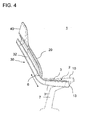
- FIG. 4 shows the seat FIG. 3 again in a page presentation.
- FIG. 5 shows an exploded view of an embodiment of the seat.
- the armrest 2 is not shown to illustrate the construction principle of the seat, in particular of the support frame 30.
- the passenger seat surface is formed by a seat part 10 and by a backrest 20.
- the seat part 10 has a seat cushion 12 which is rigidly mounted on a seat cushion support 11.
- the backrest 20 comprises a back pad 22, which is fastened on a back cushion support 21.
- the cushion support 11, 21 known from the prior art fasteners (not shown), for example, brackets, snap hooks or mounting clips.
- the seat part 10 and the backrest 20 are multi-part or multi-layered and contain, for example, each a spring mat and are provided with a cushion cover.
- the vehicle seat 1 has a rigid support frame 30, which is circumferentially disposed outside the seat part 10 and outside the backrest 20 and which is in communication with the seat cushion support 11 and the back cushion support 21.
- the support frame 30 is thus visible and is not covered by cushioning elements or by the cushion cover. Nevertheless, it can also be advantageous when using the support frame according to the invention to introduce additional support elements in the backrest or in the seat part, in particular in partial areas of the push-joint receptacle or in the knee area of the person behind.
- the support frame 30 is formed as a closed frame that surrounds the seat part and the backrest 20 peripherally.
- the support frame 30 consists of circumferential support rails 31, 32, 33, 34, 35, which are made of an aluminum hollow profile.
- the support frame 30 can in this case be made in one piece by a stretch-bending process.
- the support frame 30 has pairs of support rails 31 which extend along opposite side edges 13 of the seat part 10, in particular of the seat cushion support 11.
- the support frame 30 comprises pairs of support rails 32 which extend along opposite side edges 23 of the backrest 20, in particular of the backrest cushion support 21.
- the support rails 31 are connected to the support rails 32 via rigid, curved connecting rails 33.
- the opening angle between the horizontal support rails 31 and the obliquely upwardly inclined support rails 32 is approximately 110 degrees. Depending on the desired seat shape and other opening angle can be made by appropriate bending or shaping of the support frame 30.
- the support frame 30 is rigid and thus has no hinges. As in the FIGS. 1 to 4 shown, the support rails 31 and 33 on its upper edge on the guide groove 6, in which the armrest is displaceably guided (in FIG. 5 not shown).
Abstract
Description
- Die Erfindung betrifft einen Sitz, insbesondere einen Fahrgastsitz, mit einer verstellbaren Armlehne.
- Aus der Praxis ist es bekannt, einen Fahrgastsitz mit einer verstellbaren Armlehne auszustatten, so dass der Fahrgast die Stellung der Armlehne verändern kann. Beispielsweise ist es bekannt, einen Endbereich der Armlehne drehgelenkig zu lagern, so dass die Armlehne aus einer horizontalen Stellung hochgeklappt werden kann. Hierbei folgt das nicht drehgelenkig gelagerte Ende der Armlehne einer Kreisbahn. Ferner ist es bekannt, mittels einer Verstellvorrichtung, die unterhalb der Sitzfläche an der Tragstruktur des Sitzes angebracht ist, die Armlehne durch eine Schwenkbewegung unter die Sitzfläche zu verschwenken. Nachteile der bekannten Lösungen sind, dass eine Verstellbarkeit der horizontalen Auflagefläche, gemäß Körpergröße und Sitzposition, mehrheitlich nicht gewährleistet ist. Ferner erfordern die genannten Ausführungen aufwändige Konstruktionen. Nach Stand der Technik werden demnach in üblicher Weise separate Armlehnenmodule gefertigt, die nachträglich montiert werden. Hierdurch entstehen sowohl zusätzliche Kosten als auch Gewicht. Ein weiterer Nachteil der aus der Praxis bekannten Lösungen ist, dass sie aufgrund des benötigten Bauraums die Bewegungsfreiheit eines Hintermanns, insbesondere dessen Fußraum, einschränken.
- Es ist somit eine Aufgabe der Erfindung, einen verbesserten Sitz bereitzustellen, mit dem Nachteile herkömmlicher Sitze vermieden werden können. Die Aufgabe der Erfindung ist es insbesondere, einen Sitz, insbesondere einen Fahrgastsitz, mit einer verstellbaren Armlehne bereitzustellen, die auf einfache Art und Weise an dem Sitz montiert werden kann und gleichsam mit einem Mechanismus für eine Höhenverstellung ausgestattet ist. Ferner soll eine möglichst große Bewegungsfreiheit, insbesondere eine verbesserte Beinfreiheit eines Hintermanns, ermöglicht werden.
- Diese Aufgaben werden durch einen Sitz gemäß den Merkmalen des Hauptanspruchs gelöst. Vorteilhafte Ausführungsformen und Anwendungen der Erfindung sind Gegenstand der abhängigen Ansprüche und werden in der folgenden Beschreibung unter teilweiser Bezugnahme auf die Figuren näher erläutert.
- Erfindungsgemäß wird ein Sitz, insbesondere ein Fahrgastsitz, vorgeschlagen, mit einer Stützstruktur zur Aufnahme von Kräften, die auf den Sitz einwirken; einer Armlehne; einem Führungselement, das an der Stützstruktur, vorzugsweise an einer Tragstruktur einer Rückenlehne des Sitzes, vorgesehen ist und an dem bzw. auf dem die Armlehne zur Höhenverstellung linear verfahrbar gelagert ist; und einem Feststellmittel, mittels dessen die Armlehne in einer Verfahrposition lösbar arretierbar ist.
- Vorzugsweise ist eine horizontale Auflagefläche der Armlehne in unterschiedlichen Höhenpositionen durch lineares Verfahren der Armlehne einstellbar, so dass eine horizontale Auflagefläche unabhängig von der Position der Armlehne bereitgestellt werden kann. Ein Vorzug der Erfindung liegt somit darin, dass eine flexible Höhenverstellung der horizontalen Auflagefläche der Armlehne ermöglicht wird, um die Armlehne an verschiedene Fahrgastgrößen und/oder Sitzpositionen anpassen zu können.
- Das erfindungsgemäße Führungselement, das an der Stützstruktur vorgesehen ist bzw. als Teil der Stützstruktur ausgebildet ist oder in diese integriert ist, hat ferner den Vorteil, dass die Armlehnenhalterung funktional in die Tragstruktur des Sitzes integriert ist. Dadurch sind keine separaten Konstruktionsmittel erforderlich, um beispielsweise die Armlehne an den Sitz anzubinden, so dass auf separat tragende Teile oder große Verstellgelenke zur Halterung der Armlehnen der aus dem Stand der Technik bekannten Lösungen verzichtet werden kann. Ferner kann eine verstellbare Armlehne bereitgestellt werden kann, ohne dass ein die Bewegungsfreiheit eines Hintermanns beeinträchtigendes Drehgelenk vonnöten ist.
- Gemäß einer bevorzugten Ausgestaltungsform ist ein Schubgelenk vorgesehen, das aus dem Führungselement und einem Endabschnitt der Armlehne, welcher an dem Führungselement verschiebbar gelagert ist, gebildet ist. Mit anderen Worten kann die Armlehne mittels eines Schubgelenks relativ zu einer Tragstruktur des Sitzes bzw. relativ zur Rückenlehne verschiebbar sein.
- Das Führungselement kann beispielsweise als Führungsschiene, Laufschiene, Führungsnut oder Wellenführung ausgebildet sein.
- Gemäß einem bevorzugten Ausführungsbeispiel erstreckt sich das Führungselement zumindest entlang eines unteren Abschnitts einer Seitenkante der Rückenlehne des Sitzes, so dass die Armlehne in zumindest einem unteren Abschnitt der Rückenlehne relativ zur Rückenlehne linear verfahrbar ist. Hierbei kann das Führungselement an einem Tragelement, das sich entlang einer Seitenkante der Rückenlehne erstreckt, befestigt sein. Im Rahmen der Erfindung besteht ferner die Möglichkeit, dass das Führungselement direkt an einer Seitenkante der Rückenlehne befestigt ist.
- Gemäß einer weiteren Variante kann in die Stützstruktur eine Führungsnut eingearbeitet sein, die als das Führungselement dient. Die Stützstruktur kann das vorstehend erwähnte Tragelement umfassen. Eine Möglichkeit der erfindungsgemäßen Realisierung sieht hierbei vor, dass die Stützstruktur als außen liegende Tragstruktur ausgebildet sein kann, die außerhalb eines Rückenpolsters und/oder eines Sitzpolsters angeordnet ist.
- Bei einer vorteilhaften Variante dieser Ausgestaltungsform ist die Stützstruktur als starres Traggestell ausgebildet, umfassend mindestens eine Tragschiene, die sich seitlich entlang der Rückenlehne erstreckt. Das Führungselement kann somit vorteilhafterweise in die mindestens eine Tragschiene integriert sein und sich zumindest entlang eines Abschnitts der Tragschiene in Richtung der Längsachse der Tragschiene erstrecken. Die Tragschiene kann sich auch seitlich entlang eines Sitzteils des Sitzes erstrecken.
- Die Tragschiene dient somit als Stützelement zur Aufnahme von Kräften, die auf den Fahrzeugsitz einwirken, sowie als Führungselement für die Armlehne. Beispielsweise kann die mindestens eine Tragschiene eine Führungsnut als Führungselement für die Armlehne aufweisen.
- Gemäß einer weiteren bevorzugten Ausgestaltungsform ist die Armlehne durch Verfahren entlang dem Führungselement in einer unteren Position positionierbar, in der eine Armauflagefläche der Armlehne sich entlang einer Seitenfläche eines Sitzteils des Sitzes erstreckt. Dadurch kann die Armlehne in eine Ruheposition gebracht werden, in der sich die Armlehne an die Kontur des Sitzes anpasst und damit keinen zusätzlichen Bauraum beansprucht. Ferner wird dadurch ein komfortables Einsteigen in den und Aussteigen aus dem Sitz ermöglicht.
- Gemäß einer weiteren Variante dieser Ausgestaltungsform ist die Armlehne so dimensioniert, dass eine seitliche Kontur der Armlehne in der unteren Position der seitlichen Kontur der Sitzfläche entspricht, so dass die Armlehne in der unteren Position stufenlos an die Sitzfläche angrenzt und eine erweiterte Fläche bereitstellt, die aus der Sitzfläche und der Auflagefläche der Armlehne gebildet wird.
- Die Armlehne kann einen Trägerarm und eine auf dem Trägerarm befestigte Armauflagefläche umfassen. Vorstehend wurde bereits erwähnt, dass sich die mindestens eine Tragschiene seitlich entlang der Rückenlehne und seitlich entlang des Sitzteils des Sitzes erstrecken kann und dass die Armlehne in die untere (Ruhe-)Position verfahrbar ist. Bei einer vorteilhaften Variante der vorstehend beschriebenen Ausgestaltungsform ist der Trägerarm in der unteren Position der Armlehne von der mindestens einen Tragschiene überdeckt, so dass der Trägerarm nicht mehr sichtbar ist.
- Die Erfindung ist hinsichtlich des konstruktiven Aufbaus des Feststellmittels nicht auf einen bestimmten Aufbau beschränkt. Zum Arretieren kann das Feststellmittel beispielsweise Rasten, Sicherungsbolzen, Schrauben und/oder eine Klemm- oder Spannvorrichtung aufweisen.
- Beispielsweise kann das Feststellmittel einen Bolzen oder Rasthaken umfassen, der in eine erste Stellung bringbar ist, in der die Armlehne an dem Führungselement ortsfest arretiert ist, und der in eine zweite Stellung bringbar ist, in der die Armlehne entlang des Führungselements linear verfahrbar ist.
- In Rahmen der Erfindung besteht ferner die Möglichkeit, dass eine Höhenposition der Armlehne entlang dem Führungselement stufenlos verstellbar ist. Beispielsweise kann das Feststellmittel Klemmmittel umfassen, um einen Endbereich der Armlehne, der in dem Führungselement verfahrbar gelagert ist, in einer beliebigen Verfahrposition festzuklemmen. Ferner besteht im Rahmen der Erfindung die Möglichkeit, dass die Armlehne in vorbestimmten Verfahrpositionen arretierbar ist. Gemäß dieser Variante kann das Feststellmittel beispielsweise eine Lochrasterung, die entlang des Führungselements angeordnet ist, und ein an der Armlehne angeordnetes Einrastelement aufweisen, um die Armlehne an vorbestimmten Rasterpositionen zu arretieren.
- Eine weitere Variante der Erfindung ist gekennzeichnet durch eine im Wesentlichen unveränderte Ausrichtung einer Armauflagefläche der Armlehne während des Verfahrens der Armlehne entlang des Führungselements. Weiter vorzugsweise bleibt die Armauflagefläche der Armlehne während des Verfahrens der Armlehne entlang des Führungselements im Wesentlichen horizontal ausgerichtet. "Eine im Wesentlichen unveränderte Ausrichtung einer Armauflagefläche" kann in diesem Zusammenhang ein Verkippen der Armlehne von bis zu 10 Grad oder bis zu 20 Grad umfassen, um beispielsweise eine eingerastete Armlehne durch eine Verkippbewegung zu lösen, bevor die Armlehne entlang des Führungselements verfahren wird.
- Vorzugsweise ist das Führungselement verblendet. Diese Ausführungsvariante reduziert das Risiko, dass ein Finger oder ein Kleidungsstück beim Verfahren der Armlehne eingeklemmt wird.
- Die Erfindung ist hinsichtlich des konstruktiven Aufbaus des Sitzes nicht auf einen bestimmten Aufbau oder Sitztyp beschränkt. Eine hervorgehobene Anwendung betrifft einen Fahrgastsitz, insbesondere für Busse. Der Sitz mit der verstellbaren Armlehne kann ferner auch als ein Sitz für den Einsatz in Flugzeugen oder in Zügen ausgebildet sein. Bei einem Fahrgastsitz kann die Armlehne als Gegenarmlehne, Mittenarmlehne und/oder als Wandarmlehne ausgebildet sein.
- Vorzugsweise umfasst der Sitz ein Sitzteil, umfassend einen Sitzpolsterträger und ein Sitzpolster, das auf dem Sitzpolsterträger starr angeordnet ist. Die Rückenlehne umfasst vorzugsweise einen Rückenpolsterträger und ein Rückenpolster, das auf dem Rückenpolsterträger starr angeordnet ist.
- Es wurde vorstehend bereits erwähnt, dass das Führungselement an einer Stützstruktur des Sitzes angeordnet sein kann, insbesondere an einer Stützstruktur, die als starres Traggestell außerhalb des Sitzteils und der Rückenlehne angeordnet ist und mit dem Sitzpolsterträger und dem Rückenpolsterträger in Verbindung steht. Mit anderen Worten kann das Traggestell außerhalb des Sitzpolsterträgers, des Sitzpolsters, des Rückenpolsterträgers und des Rückenpolsters angeordnet sein.
- Gemäß einer besonders vorteilhaften Variante dieser Ausführungsform umfasst das starre Traggestell paarweise angeordnete Tragschienen, die sich entlang gegenüberliegender Seitenkanten des Sitzteils und der Rückenlehne erstrecken, wobei mindestens eine der Tragschienen das Führungselement zur Lagerung der Armlehne umfasst. Gemäß einer Variante dieser Ausführungsform weist mindestens eine der Tragschienen eine Führungsnut auf, die sich entlang der Längsachse der Tragschiene erstreckt und in der die Armlehne verschiebbar gelagert ist.
- Die Erfindung betrifft ferner ein Fahrzeug, insbesondere einen Omnibus, mit einem Sitz nach einem der vorstehend beschriebenen Aspekte. Hierbei ist zu erwähnen, dass der Sitz für den Einbau in unterschiedliche Fahrzeuge im Sinne von mobilen Verkehrsmitteln, wie beispielsweise allgemein Nutzfahrzeuge, Personenkraftwagen, Flugzeuge, Züge, Schiffe etc. geeignet ist.
- Weitere Einzelheiten und Vorteile der Erfindung werden im Folgenden unter Bezug auf die beigefügten Zeichnungen beschrieben. Es zeigen:
- Figur 1
- eine perspektivische Ansicht eines Sitzes mit der Armlehne in einer ersten Stellung gemäß einem Ausführungsbeispiel;
- Figur 2
- eine Seitenansicht des Sitzes aus
Figur 1 ; - Figur 3
- eine perspektivische Ansicht eines Sitzes mit der Armlehne in einer unteren Stellung gemäß einem Ausführungsbeispiel;
- Figur 4
- eine Seitenansicht des Sitzes aus
Figur 3 ; und - Figur 5
- eine Explosionsdarstellung des Sitzes.
-
Figur 1 zeigt beispielhaft einen Fahrgastsitz 1 mit einer verstellbaren Armlehne 2 gemäß einem Ausführungsbeispiel der Erfindung. - Die Sitz-Tragstruktur ist als starres Traggestell 30 ausgebildet, das außerhalb eines Sitzteils 10 des Sitzes 1 und außerhalb der Rückenlehne 20 umfangseitig angeordnet ist. Das Traggestell 30 weist insbesondere paarweise angeordnete Tragschienen 31 auf, die sich entlang gegenüberliegender Seitenkanten 13 des Sitzteils 10 erstrecken. Die Tragschienen 31 sind auf einem Standfuß 7 befestigt. Ferner umfasst das Traggestell 30 paarweise angeordnete Tragschienen 32, die sich entlang gegenüberliegender Seitenkanten 23 der Rückenlehne 20 erstrecken.
- Die Armlehne 2 ist mittels eines Schubgelenks relativ zur Rückenlehne 20 bzw. relativ zu einer Stützstruktur 30 höhenverstellbar. Ein besonderer Vorzug der dargestellten Ausführungsform liegt darin, dass das vorgesehene Schubgelenk in die Sitz-Tragstruktur integriert ist. Hierzu ist eine Führungsnut 6 vorgesehen, die an einer Oberseite der Tragschiene 32, die sich seitlich entlang der Rückenlehne 20 erstreckt, angeordnet ist und entlang einer Längsachse der Tragschiene 32 verläuft.
- Weitere Ausführungsformen, die nicht dargestellt sind, weisen eine Positionierung der Führungsnut auf der Innen-, Rück- oder Außenseite der Tragschiene 32 auf.
- Die Armlehne 2 umfasst einen Trägerarm 4 und eine auf dem Trägerarm 4 befestigte Armauflagefläche 3. Ein Endabschnitt 5 des Trägerarms 4 ist in der Führungsnut 6 verschiebbar gelagert. Um zu vermeiden, dass der Endabschnitt 5 aus der Führungsnut 6 herausgezogen werden kann, kann dieser T-förmig ausgebildet sein. Das Schubgelenk wird somit aus der Führungsnut 6 und dem Endabschnitt 5 gebildet. Die Führungsnut kann sich entlang der gesamten Länge der Tragschiene 32 erstrecken oder nur entlang eines unteren Abschnitts der Tragschiene 32, so dass die Armlehne 2 zumindest in einem unteren Abschnitt der Rückenlehne 20 höhenverstellbar ist.
- Ferner ist ein Feststellmittel (nicht dargestellt) vorgesehen, mittels dessen die Armlehne 2 in einer Verfahrposition entlang der Führungsnut lösbar arretierbar ist.
- Vorstehend wurde bereits erwähnt, dass der konstruktive Aufbau des Feststellmittels nicht auf einen bestimmten Aufbau beschränkt ist. Zum Arretieren kann ein an sich aus dem Stand der Technik bekanntes Feststellmittel verwendet werden, beispielsweise Rasten, Sicherungsbolzen, Schrauben und/oder eine Klemm- oder Spannvorrichtung. Im vorliegenden Ausführungsbeispiel ist an der Innenseite der Führungsnut 6 eine Lochrasterung angeordnet und am Endbereich 5 der Armlehne ein Bolzen (nicht gezeigt), der mit einem Loch der Lochrasterung in Eingriff gebracht werden kann. Am vorderen Ende der Armlehne, d. h. an dem von der Führungsnut 6 abgewandten Ende, ist ein kleiner Betätigungshebel (nicht gezeigt) vorgesehen, mittels dessen der Bolzen von einem Fahrgast entriegelt werden kann.
- In der entriegelten Stellung des Bolzens, d. h. in der nicht arretierten Stellung der Armlehne 2, ist die Armlehne 2 linear entlang der Führungsnut 6 verfahrbar. In der verriegelten Stellung ist die Armlehne an der Führungsnut 6 arretiert.
-
Figur 2 zeigt den Sitz ausFigur 1 nochmals in einer Seitendarstellung. -
Figur 3 zeigt eine perspektivische Ansicht des Sitzes mit der Armlehne 2 in einer unteren Ruheposition. Durch Verfahren der Armlehne 2 entlang der Führungsnut 6 kann die Armlehne 2 in einer unteren Position positioniert werden, in der die Armauflagefläche 3 der Armlehne 2 sich entlang der Seitenfläche 13 des Sitzteils 10 des Sitzes 1 erstreckt. In dieser Ruheposition passt sich die Armlehne 2 an die Kontur des Sitzes an und beansprucht damit keinen zusätzlichen Bauraum. Ferner ist der Trägerarm 4 in der unteren Position von der Tragschiene 31, die sich seitlich entlang des Sitzteils 10 erstreckt, überdeckt, so dass der Trägerarm 4 in dieser Stellung nicht mehr sichtbar ist. - Eine weitere, nicht dargestellte Ausführungsform beinhaltet eine Ausführung der Armauflagefläche, die in der unteren Position der seitlichen Kontur der Sitzfläche entspricht. Gemäß dieser Ausführungsvariante grenzt die Armauflagefläche in der unteren Position stufenlos an die Sitzfläche an. Hierdurch wird eine erweiterte Fläche bereitgestellt, bestehend aus Sitzfläche und mindestens einer Armlehne.
- Aus der
Figur 3 ist ferner ersichtlich, dass die räumliche Ausrichtung der Armlehne 2 in der unteren Position die gleiche ist wie in der Armauflageposition, die in denFiguren 1 und2 gezeigt ist. Dies liegt daran, dass eine im Wesentlichen horizontale Ausrichtung der Armauflagefläche 3 der Armlehne 2 bei der Verschiebung der Armlehne 2 entlang des Führungselements 6 gleich bleibt. - Die Armlehne 2 kann an einer Seite oder an beiden Seiten eines Sitzes angeordnet sein.
-
Figur 4 zeigt den Sitz ausFigur 3 nochmals in einer Seitendarstellung. -
Figur 5 zeigt eine Explosionsdarstellung eines Ausführungsbeispiels des Sitzes. In der Darstellung derFigur 5 ist die Armlehne 2 nicht dargestellt, um das Konstruktionsprinzip des Sitzes, insbesondere des Traggestells 30, zu verdeutlichen. Die Fahrgastsitzfläche wird durch ein Sitzteil 10 und durch eine Rückenlehne 20 gebildet. Das Sitzteil 10 weist ein Sitzpolster 12 auf, das auf einem Sitzpolsterträger 11 starr befestigt ist. Ebenso umfasst die Rückenlehne 20 ein Rückenpolster 22, das auf einem Rückenpolsterträger 21 befestigt ist. Zur Aufnahme und Fixierung des Sitzpolsters 12 und des Rückenpolsters 22 weisen die Polsterträger 11, 21 aus dem Stand der Technik bekannte Befestigungselemente (nicht gezeigt) auf, beispielsweise Klammern, Schnapphaken oder Befestigungsclips. Das Sitzteil 10 und die Rückenlehne 20 sind mehrteilig bzw. mehrlagig ausgebildet und enthalten beispielsweise jeweils eine Federmatte und sind mit einem Polsterüberzug versehen. - Im Gegensatz zu den aus dem Stand der Technik bekannten Fahrgastsitzen ist es nicht unbedingt erforderlich, in das Sitzteil und die Rückenlehne weitere Rahmenkonstruktionen, beispielsweise in Form eines Stahlgerüsts, einzuarbeiten, um als Stützstruktur die auf den Fahrzeugsitz 1 einwirkenden Kräfte aufnehmen zu können. Stattdessen weist der Fahrzeugsitz 1 ein starres Traggestell 30 auf, das außerhalb des Sitzteils 10 und außerhalb der Rückenlehne 20 umfangseitig angeordnet ist und das mit dem Sitzpolsterträger 11 und dem Rückenpolsterträger 21 in Verbindung steht. Das Traggestell 30 ist somit sichtbar und wird nicht durch Polsterelemente oder durch den Polsterüberzug verdeckt. Dennoch kann es auch bei Verwendung des erfindungsgemäßen Traggestells vorteilhaft sein, in der Rückenlehne oder im Sitzteil zusätzliche Stützelemente einzubringen, insbesondere in Teilbereichen der Schubgelenkaufnahme oder im Kniebereich des Hintermanns.
- Im vorliegenden Ausführungsbeispiel ist das Traggestell 30 als geschlossenes Rahmengestell ausgebildet, das das Sitzteil und die Rückenlehne 20 umfangseitig umschließt. Hierbei besteht das Traggestell 30 aus umlaufenden Tragschienen 31, 32, 33, 34, 35, die aus einem Aluminiumhohlprofil hergestellt sind. Das Traggestell 30 kann hierbei einteilig durch ein Streck-Biege-Verfahren hergestellt sein. Das Traggestell 30 weist paarweise angeordnete Tragschienen 31 auf, die sich entlang gegenüberliegender Seitenkanten 13 des Sitzteils 10, insbesondere des Sitzpolsterträgers 11, erstrecken. Ferner umfasst das Traggestell 30 paarweise angeordnete Tragschienen 32, die sich entlang gegenüberliegender Seitenkanten 23 der Rückenlehne 20, insbesondere des Rückenlehnenpolsterträgers 21, erstrecken. Die Tragschienen 31 sind mit den Tragschienen 32 über starre, gekrümmte Verbindungsschienen 33 verbunden. Der Öffnungswinkel zwischen den horizontalen Tragschienen 31 und den schräg nach oben geneigten Tragschienen 32 beträgt circa 110 Grad. Je nach gewünschter Sitzform können auch andere Öffnungswinkel durch entsprechende Biegung oder Formung des Traggestells 30 hergestellt werden. Das Traggestell 30 ist starr und weist somit keine Drehgelenke auf. Wie in den
Figuren 1 bis 4 gezeigt, weisen die Tragschienen 31 und 33 an ihrer Oberkannte die Führungsnut 6 auf, in der die Armlehne verschiebbar geführt ist (inFigur 5 nicht dargestellt). - Obwohl die Erfindung unter Bezugnahme auf bestimmte Ausführungsbeispiele beschrieben worden ist, ist eine Vielzahl von Varianten und Abwandlungen möglich, die ebenfalls von dem Erfindungsgedanken Gebrauch machen und deshalb in den Schutzbereich fallen. Folglich soll die Erfindung nicht auf die offenbarten bestimmten Ausführungsbeispiele begrenzt sein, sondern die Erfindung soll alle Ausführungsbeispiele umfassen, die in den Bereich der beigefügten Patentansprüche fallen.
-
- 1
- Fahrgastsitz
- 2
- Armlehne
- 3
- Trägerarm der Armlehne
- 4
- Armauflagefläche
- 5
- Endbereich des Trägerarms
- 6
- Führungselement, z. B. Führungsnut
- 7
- Standfuß
- 10
- Sitzteil
- 11
- Sitzpolsterträger
- 12
- Sitzpolster
- 13
- Seitenkante des Sitzpolsters
- 20
- Rückenlehne
- 21
- Rückenpolsterträger
- 22
- Rückenpolster
- 23
- Seitenkante des Rückenpolsterträgers
- 30
- Traggestell
- 31-35
- Tragschienen des Traggestells
- 40
- Kopfstütze
Claims (15)
- Sitz, insbesondere Fahrgastsitz (1), mit
einer Stützstruktur zur Aufnahme von Kräften, die auf den Sitz einwirken;
einer Armlehne (2);
einem Führungselement (6), das an der Stützstruktur vorgesehen ist und an dem die Armlehne (2) zur Höhenverstellung linear verfahrbar gelagert ist; und
einem Feststellmittel, mittels dessen die Armlehne (2) in einer Verfahrposition lösbar arretierbar ist. - Sitz nach Anspruch 1, gekennzeichnet durch ein Schubgelenk, das aus dem Führungselement (6) und einem Endabschnitt (5) der Armlehne (2), welcher an dem Führungselement (6) verschiebbar gelagert ist, gebildet ist.
- Sitz nach Anspruch 1 oder 2, dadurch gekennzeichnet, dass sich das Führungselement (6) zumindest entlang eines unteren Abschnitts einer Seitenkante (23) einer Rückenlehne (20) des Sitzes erstreckt.
- Sitz nach einem der vorhergehenden Ansprüche, dadurch gekennzeichnet, dass die Armlehne (2) in einer unteren Position positionierbar ist, in der eine Armauflagefläche (3) der Armlehne (2) sich entlang einer Seitenfläche (13) eines Sitzteils (10) des Sitzes erstreckt.
- Sitz nach einem der vorhergehenden Ansprüche, dadurch gekennzeichnet,(a) dass in die Stützstruktur eine Führungsnut eingearbeitet ist, die als das Führungselement dient; und/oder(b) dass das Führungselement (6) an einer Tragstruktur einer Rückenlehne des Sitzes vorgesehen ist.
- Sitz nach einem der vorhergehenden Ansprüche, dadurch gekennzeichnet, dass die Stützstruktur als außen liegende Tragstruktur ausgebildet ist, die außerhalb eines Rückenpolsters (20) und/oder eines Sitzpolsters (10) angeordnet ist.
- Sitz nach Anspruch 6, dadurch gekennzeichnet, dass die Stützstruktur als starres Traggestell (30) ausgebildet ist, umfassend mindestens eine Tragschiene (32), die sich seitlich entlang der Rückenlehne (20) erstreckt.
- Sitz nach Anspruch 7, dadurch gekennzeichnet, dass die mindestens eine Tragschiene (32) eine Führungsnut (6) umfasst, die als das Führungselement dient.
- Sitz nach Anspruch 7 oder 8, wenn abhängig von Anspruch 4, dadurch gekennzeichnet,(a) dass die Armlehne (2) einen Trägerarm (4) und eine auf dem Trägerarm (4) befestigte Armauflagefläche (3) umfasst, und(b) dass sich die Tragschiene (31) seitlich entlang eines Sitzteils (10) des Sitzes erstreckt; und(c) dass der Trägerarm (4) in der unteren Position von der mindestens einen Tragschiene (31) überdeckt ist, so dass der Trägerarm (4) nicht mehr sichtbar ist.
- Sitz nach einem der vorhergehenden Ansprüche, dadurch gekennzeichnet,(a) dass eine Höhenposition der Armlehne (2) entlang dem Führungselement (6) stufenlos verstellbar ist; oder(b) dass das Führungselement (6) eine Lochrasterung aufweist und die Armlehne (2) an vorbestimmten Rasterpositionen anordenbar ist.
- Sitz nach einem der vorhergehenden Ansprüche, gekennzeichnet durch eine im Wesentlichen horizontale Ausrichtung einer Armauflagefläche (3) der Armlehne (2) bei der Verschiebung der Armlehne (2) entlang des Führungselements (6).
- Sitz nach einem der vorhergehenden Ansprüche, dadurch gekennzeichnet, dass das Führungselement (6) verblendet ist.
- Sitz nach einem der vorhergehenden Ansprüche, dadurch gekennzeichnet, dass das Feststellmittel einen Bolzen oder einen Rasthaken umfasst, der in eine erste Stellung bringbar ist, in der die Armlehne an dem Führungselement ortsfest arretiert ist, und der in eine zweite Stellung bringbar ist, in der die Armlehne (2) entlang des Führungselements (6) linear verfahrbar ist.
- Sitz nach einem der Ansprüche 7 bis 13, gekennzeichnet durch:(a) ein Sitzteil (10), umfassend einen Sitzpolsterträger (11) und ein Sitzpolster (12), das auf dem Sitzpolsterträger (11) starr angeordnet ist;(b) die Rückenlehne (20), umfassend einen Rückenpolsterträger (21) und ein Rükkenpolster (22), das auf dem Rückenpolsterträger (21) starr angeordnet ist; wobei(c) das starre Traggestell (30) außerhalb des Sitzteils (10) und der Rückenlehne (20) angeordnet ist und mit dem Sitzpolsterträger (11) und dem Rückenpolsterträger (21) in Verbindung steht und paarweise angeordnete Tragschienen (31, 32) aufweist, die sich entlang gegenüberliegender Seitenkanten (13, 23) des Sitzteils und der Rückenlehne (20) erstrecken.
- Fahrzeug, insbesondere Omnibus, mit einem Sitz nach einem der vorhergehenden Ansprüche.
Applications Claiming Priority (1)
| Application Number | Priority Date | Filing Date | Title |
|---|---|---|---|
| DE102014001017.1A DE102014001017A1 (de) | 2014-01-25 | 2014-01-25 | Sitz, insbesondere Fahrgastsitz |
Publications (2)
| Publication Number | Publication Date |
|---|---|
| EP2910412A1 true EP2910412A1 (de) | 2015-08-26 |
| EP2910412B1 EP2910412B1 (de) | 2019-08-21 |
Family
ID=52349917
Family Applications (1)
| Application Number | Title | Priority Date | Filing Date |
|---|---|---|---|
| EP14004419.9A Active EP2910412B1 (de) | 2014-01-25 | 2014-12-23 | Sitz, insbesondere Fahrgastsitz |
Country Status (5)
| Country | Link |
|---|---|
| EP (1) | EP2910412B1 (de) |
| CN (1) | CN104802676B (de) |
| BR (1) | BR102015000316B1 (de) |
| DE (1) | DE102014001017A1 (de) |
| RU (1) | RU2684811C2 (de) |
Families Citing this family (4)
| Publication number | Priority date | Publication date | Assignee | Title |
|---|---|---|---|---|
| JP2017193303A (ja) * | 2016-04-22 | 2017-10-26 | 本田技研工業株式会社 | 車両用コンソール装置 |
| CN105774609A (zh) * | 2016-04-25 | 2016-07-20 | 昆山邦泰汽车零部件制造有限公司 | 带两对扶手的座椅 |
| DE102016217454A1 (de) * | 2016-09-13 | 2018-03-15 | Bos Gmbh & Co. Kg | Fahrzeugsitz |
| DE102017122387A1 (de) * | 2017-09-27 | 2019-03-28 | Airbus Operations Gmbh | Passagiersitzsystem für ein Transportmittel |
Citations (4)
| Publication number | Priority date | Publication date | Assignee | Title |
|---|---|---|---|---|
| US4239282A (en) * | 1978-12-18 | 1980-12-16 | The Boeing Company | Pilot seat |
| EP0597140A1 (de) * | 1992-11-10 | 1994-05-18 | Ignaz Vogel GmbH & Co KG, Fahrzeugsitze | Fahrgaststiz-Armlehne |
| WO2013003540A1 (en) * | 2011-06-28 | 2013-01-03 | Weber Aircraft Llc | Retractable armrest |
| JP2013136321A (ja) * | 2011-12-28 | 2013-07-11 | Daihatsu Motor Co Ltd | 車両のシート装置 |
Family Cites Families (9)
| Publication number | Priority date | Publication date | Assignee | Title |
|---|---|---|---|---|
| US3323835A (en) * | 1966-01-14 | 1967-06-06 | American Seating Co | Vehicle seat |
| US4176878A (en) * | 1978-04-24 | 1979-12-04 | Sears Manufacturing Company | Armrest structure |
| GB9814063D0 (en) * | 1998-06-29 | 1998-08-26 | Baker Martin Aircraft Co | Improvements in or relating to rotational mounting arrangements |
| US20030111888A1 (en) * | 2001-12-18 | 2003-06-19 | Brennan Edward J. | Vehicle passenger seat |
| ES2223244A1 (es) * | 2002-10-31 | 2005-02-16 | Fabricacion Asientos Vehiculos Industriales, S.A. | Butaca para vehiculos de transporte publico. |
| DE102005043890B4 (de) * | 2005-09-14 | 2014-01-30 | Lisa Dräxlmaier GmbH | Höhenverstellbare Armauflage I |
| RU61650U1 (ru) * | 2006-04-07 | 2007-03-10 | Валерий Анатольевич Богомолов | Сиденье транспортного средства |
| CN202243082U (zh) * | 2011-08-20 | 2012-05-30 | 李燕方 | 一种新型护栏座椅 |
| CN202357921U (zh) * | 2011-11-08 | 2012-08-01 | 佛山市丽江椅业有限公司 | 可升降扶手式客车座椅 |
-
2014
- 2014-01-25 DE DE102014001017.1A patent/DE102014001017A1/de not_active Withdrawn
- 2014-12-23 EP EP14004419.9A patent/EP2910412B1/de active Active
-
2015
- 2015-01-07 BR BR102015000316-1A patent/BR102015000316B1/pt active IP Right Grant
- 2015-01-16 RU RU2015101301A patent/RU2684811C2/ru active
- 2015-01-23 CN CN201510034497.3A patent/CN104802676B/zh active Active
Patent Citations (4)
| Publication number | Priority date | Publication date | Assignee | Title |
|---|---|---|---|---|
| US4239282A (en) * | 1978-12-18 | 1980-12-16 | The Boeing Company | Pilot seat |
| EP0597140A1 (de) * | 1992-11-10 | 1994-05-18 | Ignaz Vogel GmbH & Co KG, Fahrzeugsitze | Fahrgaststiz-Armlehne |
| WO2013003540A1 (en) * | 2011-06-28 | 2013-01-03 | Weber Aircraft Llc | Retractable armrest |
| JP2013136321A (ja) * | 2011-12-28 | 2013-07-11 | Daihatsu Motor Co Ltd | 車両のシート装置 |
Also Published As
| Publication number | Publication date |
|---|---|
| RU2015101301A3 (de) | 2018-09-03 |
| RU2684811C2 (ru) | 2019-04-15 |
| CN104802676A (zh) | 2015-07-29 |
| RU2015101301A (ru) | 2016-08-10 |
| BR102015000316B1 (pt) | 2022-03-15 |
| DE102014001017A1 (de) | 2015-07-30 |
| CN104802676B (zh) | 2019-10-15 |
| EP2910412B1 (de) | 2019-08-21 |
| BR102015000316A2 (pt) | 2016-06-07 |
Similar Documents
| Publication | Publication Date | Title |
|---|---|---|
| EP3575142B1 (de) | Fahrzeugsitz, insbesondere fahrgastsitz für einen bus | |
| DE10038884B4 (de) | Kopfstützenvorrichtung für Fahrzeuge | |
| DE10348939B3 (de) | Kopfstütze für einen Fahrzeusitz | |
| DE2014007B2 (de) | Befestigung eines sicherheitsgurtes an einem fahrzeugsitz | |
| EP3829931A1 (de) | Anzeigeeinrichtung und fahrzeug | |
| EP0689954A2 (de) | Sitzanordnung, insbesondere für den Lade- bzw. Fahrgastraum eines Kraftfahrzeuges | |
| DE2522074B2 (de) | Feststellvorrichtung für die Gleitführung eines in Längsrichtung verschiebbaren Kfz-Sitzes | |
| EP2910412B1 (de) | Sitz, insbesondere Fahrgastsitz | |
| DE3242593A1 (de) | Hoehenverstellvorrichtung fuer einen kraftfahrzeug-sicherheitsgurt | |
| DE2911027A1 (de) | Sitz, insbesondere fuer oeffentliche transportfahrzeuge | |
| DE1655057A1 (de) | Sitz,insbesondere fuer Kraftfahrzeuge | |
| DE102010055365A1 (de) | Tischeinrichtung für eine Sitzanlage eines Kraftwagens | |
| DE102008029261A1 (de) | Sitzanordnung für ein Kraftfahrzeug mit einem abnehmbaren Zusatzsitz | |
| WO2018215570A1 (de) | Fahrzeugsitzkonsole, fahrzeugsitz und fahrzeug | |
| DE102006043988B4 (de) | Armlehne für einen Fahrzeugsitz sowie Fahrzeugsitz mit Armlehne | |
| DE10261393A1 (de) | Höhenverstellbares Laderaumbodensystem | |
| DE102018007523B4 (de) | Sitzvorrichtung und Fahrzeug | |
| DE2612263A1 (de) | Sitzanordnung fuer fahrzeuge, insbesondere kraftfahrzeuge | |
| DE202007018960U1 (de) | Verstaubarer Fahrzeugsitz | |
| DE19919698A1 (de) | Fahrzeugsitz, insbesondere Kraftfahrzeugsitz | |
| DE102018127996A1 (de) | Scharnierbügel für sitzbaugruppe | |
| EP2946969B1 (de) | Kopfstütze für einen fahrzeugsitz | |
| DE102015211093B4 (de) | Armlehnenanordnung für einen Fahrzeuginnenraum | |
| DE102014219867B4 (de) | Komfortkopfstütze und Sitz mit einer Komfortkopfstütze | |
| DE102021211434A1 (de) | Wadenstützanordnung und Sitz |
Legal Events
| Date | Code | Title | Description |
|---|---|---|---|
| PUAI | Public reference made under article 153(3) epc to a published international application that has entered the european phase |
Free format text: ORIGINAL CODE: 0009012 |
|
| AK | Designated contracting states |
Kind code of ref document: A1 Designated state(s): AL AT BE BG CH CY CZ DE DK EE ES FI FR GB GR HR HU IE IS IT LI LT LU LV MC MK MT NL NO PL PT RO RS SE SI SK SM TR |
|
| AX | Request for extension of the european patent |
Extension state: BA ME |
|
| 17P | Request for examination filed |
Effective date: 20151127 |
|
| STAA | Information on the status of an ep patent application or granted ep patent |
Free format text: STATUS: EXAMINATION IS IN PROGRESS |
|
| 17Q | First examination report despatched |
Effective date: 20170217 |
|
| REG | Reference to a national code |
Ref country code: DE Ref legal event code: R079 Ref document number: 502014012438 Country of ref document: DE Free format text: PREVIOUS MAIN CLASS: B60N0002460000 Ipc: B60N0002750000 |
|
| GRAJ | Information related to disapproval of communication of intention to grant by the applicant or resumption of examination proceedings by the epo deleted |
Free format text: ORIGINAL CODE: EPIDOSDIGR1 |
|
| GRAP | Despatch of communication of intention to grant a patent |
Free format text: ORIGINAL CODE: EPIDOSNIGR1 |
|
| RIC1 | Information provided on ipc code assigned before grant |
Ipc: B60N 2/68 20060101ALI20190212BHEP Ipc: B60N 2/75 20180101AFI20190212BHEP |
|
| GRAP | Despatch of communication of intention to grant a patent |
Free format text: ORIGINAL CODE: EPIDOSNIGR1 |
|
| STAA | Information on the status of an ep patent application or granted ep patent |
Free format text: STATUS: GRANT OF PATENT IS INTENDED |
|
| INTG | Intention to grant announced |
Effective date: 20190322 |
|
| GRAS | Grant fee paid |
Free format text: ORIGINAL CODE: EPIDOSNIGR3 |
|
| RAP1 | Party data changed (applicant data changed or rights of an application transferred) |
Owner name: MAN TRUCK & BUS SE |
|
| GRAA | (expected) grant |
Free format text: ORIGINAL CODE: 0009210 |
|
| STAA | Information on the status of an ep patent application or granted ep patent |
Free format text: STATUS: THE PATENT HAS BEEN GRANTED |
|
| AK | Designated contracting states |
Kind code of ref document: B1 Designated state(s): AL AT BE BG CH CY CZ DE DK EE ES FI FR GB GR HR HU IE IS IT LI LT LU LV MC MK MT NL NO PL PT RO RS SE SI SK SM TR |
|
| REG | Reference to a national code |
Ref country code: GB Ref legal event code: FG4D Free format text: NOT ENGLISH |
|
| REG | Reference to a national code |
Ref country code: CH Ref legal event code: EP |
|
| REG | Reference to a national code |
Ref country code: DE Ref legal event code: R096 Ref document number: 502014012438 Country of ref document: DE |
|
| REG | Reference to a national code |
Ref country code: AT Ref legal event code: REF Ref document number: 1169355 Country of ref document: AT Kind code of ref document: T Effective date: 20190915 |
|
| REG | Reference to a national code |
Ref country code: IE Ref legal event code: FG4D Free format text: LANGUAGE OF EP DOCUMENT: GERMAN |
|
| REG | Reference to a national code |
Ref country code: SE Ref legal event code: TRGR |
|
| REG | Reference to a national code |
Ref country code: NL Ref legal event code: FP |
|
| REG | Reference to a national code |
Ref country code: LT Ref legal event code: MG4D |
|
| PG25 | Lapsed in a contracting state [announced via postgrant information from national office to epo] |
Ref country code: FI Free format text: LAPSE BECAUSE OF FAILURE TO SUBMIT A TRANSLATION OF THE DESCRIPTION OR TO PAY THE FEE WITHIN THE PRESCRIBED TIME-LIMIT Effective date: 20190821 Ref country code: LT Free format text: LAPSE BECAUSE OF FAILURE TO SUBMIT A TRANSLATION OF THE DESCRIPTION OR TO PAY THE FEE WITHIN THE PRESCRIBED TIME-LIMIT Effective date: 20190821 Ref country code: HR Free format text: LAPSE BECAUSE OF FAILURE TO SUBMIT A TRANSLATION OF THE DESCRIPTION OR TO PAY THE FEE WITHIN THE PRESCRIBED TIME-LIMIT Effective date: 20190821 Ref country code: PT Free format text: LAPSE BECAUSE OF FAILURE TO SUBMIT A TRANSLATION OF THE DESCRIPTION OR TO PAY THE FEE WITHIN THE PRESCRIBED TIME-LIMIT Effective date: 20191223 Ref country code: BG Free format text: LAPSE BECAUSE OF FAILURE TO SUBMIT A TRANSLATION OF THE DESCRIPTION OR TO PAY THE FEE WITHIN THE PRESCRIBED TIME-LIMIT Effective date: 20191121 Ref country code: NO Free format text: LAPSE BECAUSE OF FAILURE TO SUBMIT A TRANSLATION OF THE DESCRIPTION OR TO PAY THE FEE WITHIN THE PRESCRIBED TIME-LIMIT Effective date: 20191121 |
|
| PG25 | Lapsed in a contracting state [announced via postgrant information from national office to epo] |
Ref country code: IS Free format text: LAPSE BECAUSE OF FAILURE TO SUBMIT A TRANSLATION OF THE DESCRIPTION OR TO PAY THE FEE WITHIN THE PRESCRIBED TIME-LIMIT Effective date: 20191221 Ref country code: ES Free format text: LAPSE BECAUSE OF FAILURE TO SUBMIT A TRANSLATION OF THE DESCRIPTION OR TO PAY THE FEE WITHIN THE PRESCRIBED TIME-LIMIT Effective date: 20190821 Ref country code: AL Free format text: LAPSE BECAUSE OF FAILURE TO SUBMIT A TRANSLATION OF THE DESCRIPTION OR TO PAY THE FEE WITHIN THE PRESCRIBED TIME-LIMIT Effective date: 20190821 Ref country code: LV Free format text: LAPSE BECAUSE OF FAILURE TO SUBMIT A TRANSLATION OF THE DESCRIPTION OR TO PAY THE FEE WITHIN THE PRESCRIBED TIME-LIMIT Effective date: 20190821 Ref country code: RS Free format text: LAPSE BECAUSE OF FAILURE TO SUBMIT A TRANSLATION OF THE DESCRIPTION OR TO PAY THE FEE WITHIN THE PRESCRIBED TIME-LIMIT Effective date: 20190821 Ref country code: GR Free format text: LAPSE BECAUSE OF FAILURE TO SUBMIT A TRANSLATION OF THE DESCRIPTION OR TO PAY THE FEE WITHIN THE PRESCRIBED TIME-LIMIT Effective date: 20191122 |
|
| PG25 | Lapsed in a contracting state [announced via postgrant information from national office to epo] |
Ref country code: TR Free format text: LAPSE BECAUSE OF FAILURE TO SUBMIT A TRANSLATION OF THE DESCRIPTION OR TO PAY THE FEE WITHIN THE PRESCRIBED TIME-LIMIT Effective date: 20190821 |
|
| PG25 | Lapsed in a contracting state [announced via postgrant information from national office to epo] |
Ref country code: DK Free format text: LAPSE BECAUSE OF FAILURE TO SUBMIT A TRANSLATION OF THE DESCRIPTION OR TO PAY THE FEE WITHIN THE PRESCRIBED TIME-LIMIT Effective date: 20190821 Ref country code: EE Free format text: LAPSE BECAUSE OF FAILURE TO SUBMIT A TRANSLATION OF THE DESCRIPTION OR TO PAY THE FEE WITHIN THE PRESCRIBED TIME-LIMIT Effective date: 20190821 Ref country code: PL Free format text: LAPSE BECAUSE OF FAILURE TO SUBMIT A TRANSLATION OF THE DESCRIPTION OR TO PAY THE FEE WITHIN THE PRESCRIBED TIME-LIMIT Effective date: 20190821 Ref country code: RO Free format text: LAPSE BECAUSE OF FAILURE TO SUBMIT A TRANSLATION OF THE DESCRIPTION OR TO PAY THE FEE WITHIN THE PRESCRIBED TIME-LIMIT Effective date: 20190821 |
|
| PG25 | Lapsed in a contracting state [announced via postgrant information from national office to epo] |
Ref country code: SM Free format text: LAPSE BECAUSE OF FAILURE TO SUBMIT A TRANSLATION OF THE DESCRIPTION OR TO PAY THE FEE WITHIN THE PRESCRIBED TIME-LIMIT Effective date: 20190821 Ref country code: SK Free format text: LAPSE BECAUSE OF FAILURE TO SUBMIT A TRANSLATION OF THE DESCRIPTION OR TO PAY THE FEE WITHIN THE PRESCRIBED TIME-LIMIT Effective date: 20190821 Ref country code: IS Free format text: LAPSE BECAUSE OF FAILURE TO SUBMIT A TRANSLATION OF THE DESCRIPTION OR TO PAY THE FEE WITHIN THE PRESCRIBED TIME-LIMIT Effective date: 20200224 Ref country code: CZ Free format text: LAPSE BECAUSE OF FAILURE TO SUBMIT A TRANSLATION OF THE DESCRIPTION OR TO PAY THE FEE WITHIN THE PRESCRIBED TIME-LIMIT Effective date: 20190821 |
|
| REG | Reference to a national code |
Ref country code: DE Ref legal event code: R097 Ref document number: 502014012438 Country of ref document: DE |
|
| PLBE | No opposition filed within time limit |
Free format text: ORIGINAL CODE: 0009261 |
|
| STAA | Information on the status of an ep patent application or granted ep patent |
Free format text: STATUS: NO OPPOSITION FILED WITHIN TIME LIMIT |
|
| PG2D | Information on lapse in contracting state deleted |
Ref country code: IS |
|
| REG | Reference to a national code |
Ref country code: CH Ref legal event code: PL |
|
| 26N | No opposition filed |
Effective date: 20200603 |
|
| REG | Reference to a national code |
Ref country code: BE Ref legal event code: MM Effective date: 20191231 |
|
| PG25 | Lapsed in a contracting state [announced via postgrant information from national office to epo] |
Ref country code: SI Free format text: LAPSE BECAUSE OF FAILURE TO SUBMIT A TRANSLATION OF THE DESCRIPTION OR TO PAY THE FEE WITHIN THE PRESCRIBED TIME-LIMIT Effective date: 20190821 Ref country code: MC Free format text: LAPSE BECAUSE OF FAILURE TO SUBMIT A TRANSLATION OF THE DESCRIPTION OR TO PAY THE FEE WITHIN THE PRESCRIBED TIME-LIMIT Effective date: 20190821 |
|
| GBPC | Gb: european patent ceased through non-payment of renewal fee |
Effective date: 20191223 |
|
| PG25 | Lapsed in a contracting state [announced via postgrant information from national office to epo] |
Ref country code: IE Free format text: LAPSE BECAUSE OF NON-PAYMENT OF DUE FEES Effective date: 20191223 Ref country code: GB Free format text: LAPSE BECAUSE OF NON-PAYMENT OF DUE FEES Effective date: 20191223 Ref country code: LU Free format text: LAPSE BECAUSE OF NON-PAYMENT OF DUE FEES Effective date: 20191223 |
|
| PG25 | Lapsed in a contracting state [announced via postgrant information from national office to epo] |
Ref country code: LI Free format text: LAPSE BECAUSE OF NON-PAYMENT OF DUE FEES Effective date: 20191231 Ref country code: BE Free format text: LAPSE BECAUSE OF NON-PAYMENT OF DUE FEES Effective date: 20191231 Ref country code: CH Free format text: LAPSE BECAUSE OF NON-PAYMENT OF DUE FEES Effective date: 20191231 |
|
| REG | Reference to a national code |
Ref country code: AT Ref legal event code: MM01 Ref document number: 1169355 Country of ref document: AT Kind code of ref document: T Effective date: 20191223 |
|
| PG25 | Lapsed in a contracting state [announced via postgrant information from national office to epo] |
Ref country code: CY Free format text: LAPSE BECAUSE OF FAILURE TO SUBMIT A TRANSLATION OF THE DESCRIPTION OR TO PAY THE FEE WITHIN THE PRESCRIBED TIME-LIMIT Effective date: 20190821 Ref country code: AT Free format text: LAPSE BECAUSE OF NON-PAYMENT OF DUE FEES Effective date: 20191223 |
|
| PG25 | Lapsed in a contracting state [announced via postgrant information from national office to epo] |
Ref country code: HU Free format text: LAPSE BECAUSE OF FAILURE TO SUBMIT A TRANSLATION OF THE DESCRIPTION OR TO PAY THE FEE WITHIN THE PRESCRIBED TIME-LIMIT; INVALID AB INITIO Effective date: 20141223 Ref country code: MT Free format text: LAPSE BECAUSE OF FAILURE TO SUBMIT A TRANSLATION OF THE DESCRIPTION OR TO PAY THE FEE WITHIN THE PRESCRIBED TIME-LIMIT Effective date: 20190821 |
|
| PG25 | Lapsed in a contracting state [announced via postgrant information from national office to epo] |
Ref country code: MK Free format text: LAPSE BECAUSE OF FAILURE TO SUBMIT A TRANSLATION OF THE DESCRIPTION OR TO PAY THE FEE WITHIN THE PRESCRIBED TIME-LIMIT Effective date: 20190821 |
|
| PGFP | Annual fee paid to national office [announced via postgrant information from national office to epo] |
Ref country code: DE Payment date: 20221227 Year of fee payment: 9 |
|
| PGFP | Annual fee paid to national office [announced via postgrant information from national office to epo] |
Ref country code: SE Payment date: 20231222 Year of fee payment: 10 Ref country code: NL Payment date: 20231226 Year of fee payment: 10 Ref country code: IT Payment date: 20231221 Year of fee payment: 10 Ref country code: FR Payment date: 20231226 Year of fee payment: 10 |
|
| PGFP | Annual fee paid to national office [announced via postgrant information from national office to epo] |
Ref country code: DE Payment date: 20231227 Year of fee payment: 10 |