EP2906491B1 - Verfahren und vorrichtung für das befördern grossflächiger platten in extremer übergrösse - Google Patents
Verfahren und vorrichtung für das befördern grossflächiger platten in extremer übergrösse Download PDFInfo
- Publication number
- EP2906491B1 EP2906491B1 EP13798914.1A EP13798914A EP2906491B1 EP 2906491 B1 EP2906491 B1 EP 2906491B1 EP 13798914 A EP13798914 A EP 13798914A EP 2906491 B1 EP2906491 B1 EP 2906491B1
- Authority
- EP
- European Patent Office
- Prior art keywords
- comb
- grippers
- sensors
- type grippers
- glass
- Prior art date
- Legal status (The legal status is an assumption and is not a legal conclusion. Google has not performed a legal analysis and makes no representation as to the accuracy of the status listed.)
- Active
Links
Images




Classifications
-
- B—PERFORMING OPERATIONS; TRANSPORTING
- B65—CONVEYING; PACKING; STORING; HANDLING THIN OR FILAMENTARY MATERIAL
- B65G—TRANSPORT OR STORAGE DEVICES, e.g. CONVEYORS FOR LOADING OR TIPPING, SHOP CONVEYOR SYSTEMS OR PNEUMATIC TUBE CONVEYORS
- B65G49/00—Conveying systems characterised by their application for specified purposes not otherwise provided for
- B65G49/05—Conveying systems characterised by their application for specified purposes not otherwise provided for for fragile or damageable materials or articles
- B65G49/06—Conveying systems characterised by their application for specified purposes not otherwise provided for for fragile or damageable materials or articles for fragile sheets, e.g. glass
- B65G49/061—Lifting, gripping, or carrying means, for one or more sheets forming independent means of transport, e.g. suction cups, transport frames
-
- B—PERFORMING OPERATIONS; TRANSPORTING
- B65—CONVEYING; PACKING; STORING; HANDLING THIN OR FILAMENTARY MATERIAL
- B65G—TRANSPORT OR STORAGE DEVICES, e.g. CONVEYORS FOR LOADING OR TIPPING, SHOP CONVEYOR SYSTEMS OR PNEUMATIC TUBE CONVEYORS
- B65G47/00—Article or material-handling devices associated with conveyors; Methods employing such devices
- B65G47/74—Feeding, transfer, or discharging devices of particular kinds or types
- B65G47/90—Devices for picking-up and depositing articles or materials
- B65G47/91—Devices for picking-up and depositing articles or materials incorporating pneumatic, e.g. suction, grippers
- B65G47/918—Devices for picking-up and depositing articles or materials incorporating pneumatic, e.g. suction, grippers with at least two picking-up heads
-
- B—PERFORMING OPERATIONS; TRANSPORTING
- B65—CONVEYING; PACKING; STORING; HANDLING THIN OR FILAMENTARY MATERIAL
- B65G—TRANSPORT OR STORAGE DEVICES, e.g. CONVEYORS FOR LOADING OR TIPPING, SHOP CONVEYOR SYSTEMS OR PNEUMATIC TUBE CONVEYORS
- B65G47/00—Article or material-handling devices associated with conveyors; Methods employing such devices
- B65G47/74—Feeding, transfer, or discharging devices of particular kinds or types
- B65G47/90—Devices for picking-up and depositing articles or materials
- B65G47/92—Devices for picking-up and depositing articles or materials incorporating electrostatic or magnetic grippers
-
- B—PERFORMING OPERATIONS; TRANSPORTING
- B65—CONVEYING; PACKING; STORING; HANDLING THIN OR FILAMENTARY MATERIAL
- B65G—TRANSPORT OR STORAGE DEVICES, e.g. CONVEYORS FOR LOADING OR TIPPING, SHOP CONVEYOR SYSTEMS OR PNEUMATIC TUBE CONVEYORS
- B65G49/00—Conveying systems characterised by their application for specified purposes not otherwise provided for
- B65G49/05—Conveying systems characterised by their application for specified purposes not otherwise provided for for fragile or damageable materials or articles
- B65G49/06—Conveying systems characterised by their application for specified purposes not otherwise provided for for fragile or damageable materials or articles for fragile sheets, e.g. glass
- B65G49/067—Sheet handling, means, e.g. manipulators, devices for turning or tilting sheet glass
-
- B—PERFORMING OPERATIONS; TRANSPORTING
- B65—CONVEYING; PACKING; STORING; HANDLING THIN OR FILAMENTARY MATERIAL
- B65G—TRANSPORT OR STORAGE DEVICES, e.g. CONVEYORS FOR LOADING OR TIPPING, SHOP CONVEYOR SYSTEMS OR PNEUMATIC TUBE CONVEYORS
- B65G49/00—Conveying systems characterised by their application for specified purposes not otherwise provided for
- B65G49/05—Conveying systems characterised by their application for specified purposes not otherwise provided for for fragile or damageable materials or articles
- B65G49/06—Conveying systems characterised by their application for specified purposes not otherwise provided for for fragile or damageable materials or articles for fragile sheets, e.g. glass
- B65G49/068—Stacking or destacking devices; Means for preventing damage to stacked sheets, e.g. spaces
-
- B—PERFORMING OPERATIONS; TRANSPORTING
- B65—CONVEYING; PACKING; STORING; HANDLING THIN OR FILAMENTARY MATERIAL
- B65G—TRANSPORT OR STORAGE DEVICES, e.g. CONVEYORS FOR LOADING OR TIPPING, SHOP CONVEYOR SYSTEMS OR PNEUMATIC TUBE CONVEYORS
- B65G57/00—Stacking of articles
- B65G57/02—Stacking of articles by adding to the top of the stack
- B65G57/08—Stacking of articles by adding to the top of the stack articles being tilted or inverted prior to depositing
-
- B—PERFORMING OPERATIONS; TRANSPORTING
- B65—CONVEYING; PACKING; STORING; HANDLING THIN OR FILAMENTARY MATERIAL
- B65G—TRANSPORT OR STORAGE DEVICES, e.g. CONVEYORS FOR LOADING OR TIPPING, SHOP CONVEYOR SYSTEMS OR PNEUMATIC TUBE CONVEYORS
- B65G61/00—Use of pick-up or transfer devices or of manipulators for stacking or de-stacking articles not otherwise provided for
-
- B—PERFORMING OPERATIONS; TRANSPORTING
- B65—CONVEYING; PACKING; STORING; HANDLING THIN OR FILAMENTARY MATERIAL
- B65G—TRANSPORT OR STORAGE DEVICES, e.g. CONVEYORS FOR LOADING OR TIPPING, SHOP CONVEYOR SYSTEMS OR PNEUMATIC TUBE CONVEYORS
- B65G2201/00—Indexing codes relating to handling devices, e.g. conveyors, characterised by the type of product or load being conveyed or handled
- B65G2201/02—Articles
- B65G2201/0214—Articles of special size, shape or weigh
- B65G2201/022—Flat
-
- B—PERFORMING OPERATIONS; TRANSPORTING
- B65—CONVEYING; PACKING; STORING; HANDLING THIN OR FILAMENTARY MATERIAL
- B65G—TRANSPORT OR STORAGE DEVICES, e.g. CONVEYORS FOR LOADING OR TIPPING, SHOP CONVEYOR SYSTEMS OR PNEUMATIC TUBE CONVEYORS
- B65G2249/00—Aspects relating to conveying systems for the manufacture of fragile sheets
- B65G2249/04—Arrangements of vacuum systems or suction cups
- B65G2249/045—Details of suction cups suction cups
Definitions
- the invention relates to the implementation of large-scale plates in extreme oversize.
- Extrem oversize here are understood dimensions over 40 meters in length and over 6 meters in width.
- it is glass plates.
- the production of large-area glass plates takes place in the form of float glass by the continuous pouring of a molten glass on a heated in an elongated tub tin bath and the resulting glass ribbon.
- This glass band has a side on which lay on the tin bath, the so-called bath side.
- the other side of the glass ribbon which has been cooled in the air is referred to as the so-called air side.
- the bath side and the air side have different properties. For example, as the air side has less bumps, it is better for coatings.
- the subsequent assembly of the float glass is done by slitting and cross-cutting the expiring from the float glass production at a certain feed rate glass ribbon.
- tape measure or large format here is a size of 6 meters by 3.21 meters called.
- split tape measure or medium format is called a plate size of 3.21 meters by 2 meters (to 2.5 meters).
- this holding mechanisms usually in the form of a stable frame, moved up to the glass plate in question, connected to this via suction cups, and then the holding mechanism with the suctioned thereto Glass plate further transported.
- a device for plate transfer from a plate conveyor on a stacking rack or the like is described, with a robot with a robot arm at its free end a suction frame or the like for receiving a plate from the plate conveyor, and equipped with a sufficient for its movement function number of degrees of freedom is.
- the development of such a device is based on the object, a device for plate transfer from a plate conveyor on a stacking frame in such a way that, in the case of a glass plate, if possible, no adverse effect on the air side of the glass.
- the plate conveyor is provided with a recess in which the robot arm can dip, and with, a dipping of the suction frame or the like enabling recesses. Furthermore, the suction frame or the like at the free end of the robot arm in a after Upwardly facing position to be arranged to pivot from the dipping into the recesses of the plate conveyor position a plate on its side facing the plate conveyor side.
- the stacking rack used here is immovably fixed to the ground, so it can only be equipped by the, the robotic arm facing page.
- the stacking frame must each be moved away when loading with another glass plate by the small distance of the thickness of a glass plate from the robot arm, since the distance of the robot arm is a fixed size.
- so-called clock slides are necessary in practice in the current state of the art, which move the stacking frame each time before loading with a new glass plate by the distance of a glass plate - thickness of the robot arm to make room for another glass plate.
- a turntable is necessary for loading the stacking rack from the other side. For loading the stacking rack with large and heavy glass plates of the required clock slide and the required hub of the load occurring are designed according to consuming and very expensive to manufacture.
- FR 1 541 340 A and FR 2 525 196 A1 are devices for automatically breaking a glass sheet and for conveying glass plates known, with a lifting device on the left or right at an angle up to 90 degrees pivot.
- the device according to the invention or the corresponding method is therefore based on the task to record in the normal position of very large glass plates in maximum dimensions, ie over 40 meters in length and over 6 meters in width, on the production line in the shortest possible time, vibration-free and safe to stack. Since such a plate also has to be coated and such a coating is usually applied to the smoother side, namely the air side, it is necessary to be able to detect this plate from the bath side as well.
- the Fig. 1 shows a perspective view of a part of the overall device according to the invention. Since the device according to the invention involves the transport of glass plates of extreme oversize, namely of the order of more than 40 meters in length and over 6 meters in width, it can be seen that in the Fig.1 not the entire transport system can be represented in its entire length. This also does not seem necessary since the structure of the means of transport does not change over the entire length of the installation.
- FIG. 1 In the Fig. 1 can be seen how the portal supports 1, connected by the far exciting guide carrier 2, so to speak form a wide portal that has given such a portal converter its name.
- This stable construction ensures that on the one hand between the portal supports 1 enough space is created to accommodate even very large glass plates 10 and perform the desired place and on the other hand Positioning accuracy of the respective column carriage 3, each carrying a lifting column 4, even when handling very large and very heavy glass plates 10 is maintained.
- the compressed air required for this Vorgag is stored in the compressed air tank 7.
- the compressed air tank 7 In a similar way it is achieved that the, the movement of a particular glass plate 10 transmitting, timing belt are not claimed inadmissible. In addition, it is achieved that the flanks of the toothed belts used are only loaded on one side and the control can thus be very precise overall. With this device, it is of course also possible to "overcompensate" the weight of a glass plate 10 and thus make it seem easier for the process of conversion than their actual weight corresponds. Such an approach may appear in the individual case in the implementation of particularly heavy glass plates 10 displayed.
- the horizontally acting carriage drive 6 in the form of a servomotor moves the respective column carriage 3. In the conduit 8 shown, the energy supply and the control for the respective lifting column 4 run.
- a vacuum pump 9 supplies the vacuum required for the respective vacuum cleaner 12, wherein the vacuum cleaner 12 are attached to the transversely extending to a roller conveyor cross members 11, which are drawn here stylized horizontal lying.
- a switch box 13 in the region of the foremost suckers 12, an electrical control box 13 is installed.
- Fig. 1 From the portal support structure just described, only 3 exemplars are shown in succession.
- glass plate 10 With the length of the transported Of course, glass plate 10 also increases the number of portal doors required, whereby the total weight of a glass plate 10 is distributed among the available portal doors. Of course, with the increase in the width of a glass plate 10 to be conveyed, its weight also increases. This, of course, also affects the density of the portals arranged next to one another, that is to say also their number.
- Fig. 2 is a sectional view through the overall device shown.
- the above-mentioned facilities can be seen for the most part also from the sectional drawing of this figure.
- the column drive 14 can be seen here, which executes the vertical movement of the lifting column 4 in the form of a servomotor.
- On the left side of a stacking rack 15 and on the right side of a stacking rack 16 are shown in section.
- a glass plate 10 is mounted on a vertical lifting device 20 in an inclined position.
- This device has a comb-like structure, the finger-like supporting elements of which are covered with suckers 12 which can not be seen in this illustration.
- suckers 12 which can not be seen in this illustration.
- Fig. 4 directed please refer to the Fig. 4 directed.
- the glass plate 10 has been pivoted by means of its pivoting - drive 19, said vertical lifting device 20 has lifted from below through the conveyor rollers 17, the glass plate 10 by means of said comb-like structure.
- the drive by means of which the conveyor rollers 17 have spent the glass band to be conveyed in the region of the system according to the invention is designated by 18.
- the vertical lifting device 20 is by means of its suction 12 in a position to pivot a glass plate to an angle of about 90 degrees.
- the lifting column 4 carries in the Fig. 2 a turning and pivoting device 21 which is associated with a comb gripper 22.
- the comb gripper 22 is able to detect the glass plate 10 from above, in this case from the air side, and, after pivoting the vertical lifting device 20 on the set down right stacking rack 16.
- field sensors 24 are installed on each gantry support, which are directed towards each other. Their meaning will be explained later.
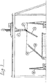
- the Fig. 3 shows a further sectional view through the entire device.
- a comb gripper 22 which is moved by a pivoting and rotating device 21 by means of a lifting column 4, engages from below by a vertical lifting device 20 and detects a glass plate 10 on the bath side.
- the vertical lifting device 20 pivots downward and the comb gripper 22 lifts the glass plate 10 up and sets it, with the bath side up, on the left stacking rack 15.
- On the right stacking rack 16 an already parked other glass plate 10 is shown.
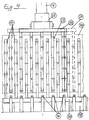
- the Fig. 4 shows a detailed drawing of a comb gripper 22.
- This comb gripper 22 is guided and guided by means of the pivoting and rotating device 21 and it is moved by means of the lifting column 4 shown centrally. Since each comb gripper 22 must be able to rotate about the central axis of its lifting column 4 in the course of its movement program to change position with dense portal supports, the invention provides that each comb gripper 22 by means of a respective telescopic device 27 on both sides of the width of its detection range can change.
- the right side of the comb gripper shown 22 dashed lines. On the left side here suckers 12 are shown upon detection of a glass plate 10.
- the glass plate 10 Since the glass plate 10 is transparent, the finger-like supporting elements of the comb-like lifting structure of the vertical lifting device 20 with its suckers 12 can be seen in this illustration. Other sucker are marked only by crosses. At the lower edge of the picture, the conveying rollers 17 can be seen in cross section and the drive 19 for the vertical lifting device 20.
- a sectional drawing is shown with 2 lifting columns.
- the vertical lifting device 20 may be hinged on the left side or the right side.
- two different comb grippers 22 are shown to illustrate that in this way both the left stacking rack 15 and the right stacking rack 16 can be loaded directly by the vertical lifting device 20.
- Shown here are again the field sensors 24, to which reference is made later. Additional sensors 26 for Detecting the gripper facilitate the fine control of the comb gripper 22 with each other.
- Fig. 6 is a distribution scheme outlined by gripping elements. So far, the structure and function of the comb gripper 22 were treated, with only suckers 12, so to speak as sole function carriers, was spoken. In the Figure 6 It is further pointed out that for the transportation and protection of such a huge glass plate 10 it is necessary to equip the comb grippers used with different types of suckers 12. Thus, it is shown here by way of example on a stylized glass plate 10 that preferably so-called power suckers 39 are used in addition to more precision suckers 40 which serve more precisely for the purpose of fixing. Since it is important for the subsequent coating of a glass plate 10 to have no impressions of suction rings in the middle, so-called electrostatic grippers 41 are preferably used in this area. Such electrostatic grippers are state of the art and can transfer forces of up to 20 N / cm 2 transversely to the workpiece surface (Ref.Nr .: 1981 RWTH Aachen). In addition, unspecified ultrasound grippers are additionally used.
- nipple consists essentially of a sucker shaft 28 which is inserted in a guide and support tube 34 and of a suction plate 31 fastened to it.
- a compensating spring 29, which is mounted between the guide and support tube 34 and the suction plate 31, ensures on the one hand a gentle placement of the suction cup 31 on the glass plate 10 and on the other hand it supports the flexible Saugtellerhalterung 30 at an inclination.
- This Saugtellerhalterung is made of a soft, but good shock-absorbing material and provides a harmonious connection between the Saugerschaft 28 and the suction cup 31 circular Saugermanschette 32 with its particularly adhesive edge lip makes the actual connection to the glass plate 10 ago.
- the suction cup 31 has a circular filter element 33 in its center. This serves the purpose of keeping fine glass particles away from the vacuum pump 9. It can either cleaned by hand or replaced at regular intervals.
- the on resistance of the filter element 33 of each sucker 39 can be detected in a particular stage and displayed on a monitor. Furthermore, it can be provided that individual suckers can be switched off individually and / or can be subjected to adjustable negative pressure air.
- the Fig. 8 shows a section through a so - called precision suction 40.
- This illustration shows the special effect of this nipple. Since it is important for the slices to be picked up, that they are transported and applied absolutely in a level position, the area with which the respective slice is touched by the respective suction head must also be absolutely even with every suction head. This is achieved in that in the illustration shown, the sealing ring 37 is guided in a suction head 38 made of solid material. The suction head 38 slides in this case together with the rubber bellows 36 in the holding plate 35. A wave-shaped bending of the recorded disc at the points of attack of the respective suckers, as to fear in other embodiments in the prior art with flexible sealing lip, this is excluded.
- the suction head 38 may in this case also be approximately square or have any other desired surface shape, for example, which induces as little mechanical stress as possible in the respectively recorded disk.
- an elliptical shaped surface may contribute to reducing stresses during picking and transport in the respective disc.
- the Fig. 9 shows a representation of the synchronization of the comb gripper 22.
- three comb grippers 22 are shown side by side, each carrying two laser sensors 42 at the two ends of their outer finger-like support elements.
- These laser sensors 42 are capable of emitting laser beams for communication with the respectively adjacent comb gripper 22, but also to receive such communication signals. In this way it is possible for a central control to align all the comb grippers required for the transport of the respective glass plate 10 in a row and at a height in a straight line. Since such adjacent laser sensors 42 can also communicate diagonally, In this way, it is possible to detect twisting of individual comb grippers 22 and to correct them in terms of control technology.
- the level of the totality of the comb gripper 22 used in this way forms the starting point for the determination of the distances of the individual, referred to at this point adhesive elements, suction or electrostatic gripper, to the glass plate 10. Since each of the respective adhesive elements a different printing behavior, or damping behavior during the adhesion process, can be achieved in this way by means of the construction of a, at least in groups, individual suction pressure, or adhesion pressure over the entire surface of a glass plate 10, a relatively constant contact pressure. For this group-oriented additional distance sensors are provided, which are not drawn for reasons of clarity and are not provided with reference numerals. In principle, of course, each individual adhesive element could be assigned such a sensor, but in the treatment of such a large glass plate 10 due to the resulting data wealth technical and economic limits.
- portal supports (1), the comb gripper (22) and the vertical - lifting device (22) can of course also be applied sporadically.
- mini-lenses which collect optical information in the form of hundreds of mini-lenses according to the light field principle, which can later be compiled into images with a desired resolution and / or a desired viewing angle.
- miniature lenses are 3 - D able to produce cheaply and follow the principle of an insect eye.
Landscapes
- Engineering & Computer Science (AREA)
- Mechanical Engineering (AREA)
- Manipulator (AREA)
- Length Measuring Devices By Optical Means (AREA)
- Re-Forming, After-Treatment, Cutting And Transporting Of Glass Products (AREA)
Priority Applications (1)
| Application Number | Priority Date | Filing Date | Title |
|---|---|---|---|
| PL13798914T PL2906491T3 (pl) | 2012-10-09 | 2013-09-26 | Sposób i urządzenie do transportowania płyt wielkopowierzchniowych o bardzo dużych wymiarach |
Applications Claiming Priority (2)
| Application Number | Priority Date | Filing Date | Title |
|---|---|---|---|
| DE102012019839.6A DE102012019839B4 (de) | 2012-10-09 | 2012-10-09 | Verfahren und Vorrichtung für das Befördern großflächiger Platten in extremer Übergröße |
| PCT/DE2013/000549 WO2014056469A1 (de) | 2012-10-09 | 2013-09-26 | Verfahren und vorrichtung für das befördern grossflächiger platten in extremer übergrösse |
Publications (2)
| Publication Number | Publication Date |
|---|---|
| EP2906491A1 EP2906491A1 (de) | 2015-08-19 |
| EP2906491B1 true EP2906491B1 (de) | 2017-07-26 |
Family
ID=49683380
Family Applications (1)
| Application Number | Title | Priority Date | Filing Date |
|---|---|---|---|
| EP13798914.1A Active EP2906491B1 (de) | 2012-10-09 | 2013-09-26 | Verfahren und vorrichtung für das befördern grossflächiger platten in extremer übergrösse |
Country Status (9)
| Country | Link |
|---|---|
| US (1) | US10377583B2 (pl) |
| EP (1) | EP2906491B1 (pl) |
| CN (1) | CN104755396B (pl) |
| DE (1) | DE102012019839B4 (pl) |
| EA (1) | EA031717B1 (pl) |
| ES (1) | ES2639193T3 (pl) |
| IL (1) | IL238039B (pl) |
| PL (1) | PL2906491T3 (pl) |
| WO (1) | WO2014056469A1 (pl) |
Families Citing this family (34)
| Publication number | Priority date | Publication date | Assignee | Title |
|---|---|---|---|---|
| DE102012019839B4 (de) | 2012-10-09 | 2017-08-24 | Grenzebach Maschinenbau Gmbh | Verfahren und Vorrichtung für das Befördern großflächiger Platten in extremer Übergröße |
| DE102012020679B4 (de) * | 2012-10-22 | 2022-01-05 | Grenzebach Maschinenbau Gmbh | Verfahren und Vorrichtung zum schnellen Versetzen von Platten |
| NL2012515B1 (en) * | 2014-03-27 | 2016-01-19 | Vmi Holland Bv | Unloading system and method for unloading a tire tread carrier. |
| DE102015200727B4 (de) * | 2015-01-19 | 2025-03-06 | Krones Aktiengesellschaft | Vorrichtung und Verfahren zum Positionieren einzelner Zwischenlagen eines Zwischenlagenstapels auf zugeordneten Paletten |
| US9925634B2 (en) | 2015-04-16 | 2018-03-27 | Cardinal Ig Company | Automated seaming apparatus and method |
| US10124359B2 (en) | 2015-06-17 | 2018-11-13 | Integrated Construction Enterprises, Inc. | Autonomous painting systems and related methods |
| US11919019B2 (en) | 2015-06-17 | 2024-03-05 | Revolutionice Inc. | Autonomous painting systems and related methods |
| ITUB20152339A1 (it) * | 2015-07-21 | 2017-01-21 | Giuseppe Gallucci | Apparecchiatura per il ribaltamento di fogli e/o pannelli |
| CN106241408B (zh) * | 2016-08-31 | 2019-05-03 | 中冶华天工程技术有限公司 | 后置驱动的高速码垛系统 |
| CN108792536B (zh) * | 2017-04-28 | 2023-11-14 | 惠州中科先进制造有限公司 | 一种电视背壳检测、翻转及堆叠生产线 |
| CN108750672A (zh) * | 2018-05-13 | 2018-11-06 | 南京朝阳玻璃有限公司 | 玻璃四维抓取移动装置 |
| CN109436827B (zh) * | 2018-12-12 | 2020-12-04 | 合肥动联自动化科技有限公司 | 一种码垛机抓取机构 |
| CN109573612A (zh) * | 2019-01-29 | 2019-04-05 | 永州市亿达自动化机械有限公司 | 一种带有玻璃切割功能的自动上料机 |
| US11111086B2 (en) | 2019-11-11 | 2021-09-07 | Cardinal Ig Company | Glass stacking systems and methods |
| US11536083B2 (en) | 2020-05-22 | 2022-12-27 | Cardinal Ig Company | Automated spacer processing systems and methods |
| CN112047120A (zh) * | 2020-07-31 | 2020-12-08 | 南京灵雀智能制造有限公司 | 一种易碎餐盘码垛托盘夹具及夹取方法 |
| CN111807045A (zh) * | 2020-08-25 | 2020-10-23 | 河南工业职业技术学院 | 一种自动抓举与运输机械零件的机电设备 |
| CN112758576B (zh) * | 2020-12-27 | 2022-11-18 | 九江职业技术学院 | 一种新型物流仓储用智能存储货架装置 |
| CN112919131A (zh) * | 2021-02-22 | 2021-06-08 | 李欢欢 | 一种产品植入机的自动上料装置及其控制方法 |
| CN113264311B (zh) * | 2021-07-20 | 2021-09-21 | 江苏易库科技有限公司 | 储放仓分板输送装置 |
| US12312187B2 (en) * | 2021-08-31 | 2025-05-27 | Intelligrated Headquarters, Llc | Robotic system for stacking and de-stacking |
| CN113830558A (zh) * | 2021-09-18 | 2021-12-24 | 甘肃光轩高端装备产业有限公司 | 玻璃基板的传输装置 |
| CN113859980A (zh) * | 2021-10-19 | 2021-12-31 | 蚌埠凯盛工程技术有限公司 | 一种超长玻璃多单元同步堆垛装置及其控制系统 |
| CN114229470B (zh) * | 2021-12-10 | 2023-10-27 | 中国建材国际工程集团有限公司 | 一种玻璃输送装置以及玻璃输送堆垛方法 |
| CN113979135B (zh) * | 2021-12-29 | 2022-04-08 | 四川和乐门业有限公司 | 一种可直接转运的门扇打包翻转堆垛架及其使用方法 |
| WO2023144785A1 (en) * | 2022-01-31 | 2023-08-03 | Muratori Machines S.R.L. | Device for loading flat elements onto a work table of a machine tool |
| CN115367435A (zh) * | 2022-09-23 | 2022-11-22 | 康佳集团股份有限公司 | 一种对位系统及其对位方法、大尺寸电视的生产线 |
| CN115258693B (zh) * | 2022-09-29 | 2022-12-27 | 江苏延陵玻璃有限公司 | 一种真空复合玻璃夹持翻转装置 |
| CN115924532B (zh) * | 2022-12-28 | 2025-05-30 | 博众精工科技股份有限公司 | 一种更换玻璃卡塞的设备 |
| EP4652349A1 (en) | 2023-01-20 | 2025-11-26 | Cardinal CG Company | Aerogel molding and handling technology, multiple-pane insulating glazing units incorporating aerogel, and ig unit manufacturing methods |
| CN116331842B (zh) * | 2023-03-31 | 2023-10-27 | 江苏神州新能源电力有限公司 | 一种光伏板生产用钢化玻璃输送平台 |
| CN116788845B (zh) * | 2023-05-26 | 2025-11-28 | 彩虹(合肥)液晶玻璃有限公司 | 一种玻璃基板半成品pe膜铺膜机构 |
| CN117303004B (zh) * | 2023-11-17 | 2024-06-04 | 河北普阳钢铁有限公司 | 一种铸坯生产钢板的转运装置及转运方法 |
| CN119858747B (zh) * | 2024-12-30 | 2025-09-19 | 徐州环亚交通运输设备有限公司 | 一种半挂车箱体边板拼装工装 |
Citations (1)
| Publication number | Priority date | Publication date | Assignee | Title |
|---|---|---|---|---|
| US20040240981A1 (en) * | 2003-05-29 | 2004-12-02 | I-Scan Robotics | Robot stacking system for flat glass |
Family Cites Families (28)
| Publication number | Priority date | Publication date | Assignee | Title |
|---|---|---|---|---|
| DE1596352C3 (de) * | 1966-10-18 | 1974-07-04 | Asahi Glass Co. Ltd., Tokio | Vorrichtung zum Abbrechen und Abtransportieren einer Glasplatte von einer sich kontinuierlichen nach oben bewegenden bandförmigen Glastafel |
| FR1541340A (fr) * | 1966-10-18 | 1968-10-04 | Asahi Glass Co Ltd | Appareil à diviser automatiquement une nappe de verre et à évacuer les plaques deverre détachées |
| US4228886A (en) * | 1978-12-26 | 1980-10-21 | Ppg Industries, Inc. | Position sensor |
| FR2525196A1 (fr) * | 1982-04-16 | 1983-10-21 | Saint Gobain Vitrage | Dispositif pour le transfert de feuilles de verre d'un premier poste, ou elles sont en une position sensiblement verticale, jusqu'a un second poste, ou elles sont en une position sensiblement horizontale |
| NO161311C (no) * | 1983-02-24 | 1989-08-02 | Reinhard Goepfert | Selvdrevet innretning for hevning og forflytning av elementer som skal loeftes. |
| DE3539879A1 (de) * | 1985-11-11 | 1987-05-21 | Karl Lenhardt | Vorrichtung fuer das schlupffreie foerdern von zwei tafeln, insbesondere von glastafeln |
| DE19712368A1 (de) | 1997-03-25 | 1998-10-01 | Hans Hager | Verfahren und Vorrichtung zum Versetzen eines Gegenstandes |
| US6364386B1 (en) * | 1999-10-27 | 2002-04-02 | Agilent Technologies, Inc. | Apparatus and method for handling an integrated circuit |
| IT1319920B1 (it) * | 2000-02-25 | 2003-11-12 | Bottero Spa | Gruppo di presa e movimentazione aerea di lastre di vetro. |
| US7367601B2 (en) * | 2000-06-29 | 2008-05-06 | Shibaura Mechatronics Corporation | Substrate transfer apparatus and substrate transfer method |
| DE10148038A1 (de) | 2001-09-28 | 2003-04-17 | Grenzebach Maschb Gmbh | Einrichtung zur Plattenübergabe von einem Plattenförderer auf ein Stapelgestell oder dergleichen |
| ITVI20020082A1 (it) * | 2002-05-03 | 2003-11-03 | Erre Automazioni Srl 3 | Gruppo scaricatore ad apertura controllata per la movimentazione di prodotto |
| US6807461B2 (en) * | 2002-05-22 | 2004-10-19 | Kuka Roboter Gmbh | Coordinated robot control from multiple remote instruction sources |
| DE10232080B4 (de) * | 2002-07-15 | 2015-10-01 | Integrated Dynamics Engineering Gmbh | Elektrostatischer Greifer und Verfahren zu dessen Herstellung |
| DE20216636U1 (de) * | 2002-10-28 | 2004-03-11 | Kuka Schweissanlagen Gmbh | Bearbeitungsanlage |
| JP2004193195A (ja) * | 2002-12-09 | 2004-07-08 | Shinko Electric Ind Co Ltd | 搬送装置 |
| US20060099064A1 (en) * | 2004-11-08 | 2006-05-11 | Yaron Anaki | On-the-fly robotic stacking system for flat glass |
| DE102005060452A1 (de) * | 2005-12-17 | 2007-06-28 | Armatec Vierhaus Gmbh | Handhabungsvorrichtung |
| DE102006017763B4 (de) * | 2006-04-12 | 2009-12-17 | Schott Ag | Dünnglasgreifer |
| US7628434B2 (en) * | 2006-07-12 | 2009-12-08 | Honda Motor Co., Ltd. | Vacuum-operated vehicle glass handling system |
| DE202008001422U1 (de) * | 2008-01-31 | 2008-03-27 | Grenzebach Maschinenbau Gmbh | Portalumsetzer für großflächige Glasplatten |
| DE102008006956B3 (de) | 2008-01-31 | 2009-09-03 | Grenzebach Maschinenbau Gmbh | Portalumsetzer für großflächige Glasplatten |
| DE102008045369B4 (de) * | 2008-09-02 | 2013-11-21 | Grenzebach Maschinenbau Gmbh | Vorrichtung und Verfahren zum Aufnehmen von Glasplatten |
| CN102363474A (zh) * | 2011-06-16 | 2012-02-29 | 安徽省银锐玻璃机械有限公司 | 玻璃双翻单工位上片机的上片传动机构 |
| US9969131B2 (en) * | 2011-06-22 | 2018-05-15 | The Boeing Company | Automated ply layup system |
| SI2546153T1 (sl) * | 2011-07-13 | 2016-01-29 | Schuler Automation Gmbh & Co. Kg | Naprava in postopek za skladanje delov, ki jih je moč skladati |
| CN102620712B (zh) * | 2012-04-12 | 2013-09-11 | 湖南路桥建设集团公司 | 一种利用激光测距仪实现同步的方法及装置 |
| DE102012019839B4 (de) | 2012-10-09 | 2017-08-24 | Grenzebach Maschinenbau Gmbh | Verfahren und Vorrichtung für das Befördern großflächiger Platten in extremer Übergröße |
-
2012
- 2012-10-09 DE DE102012019839.6A patent/DE102012019839B4/de not_active Expired - Fee Related
-
2013
- 2013-09-26 EA EA201590532A patent/EA031717B1/ru not_active IP Right Cessation
- 2013-09-26 EP EP13798914.1A patent/EP2906491B1/de active Active
- 2013-09-26 PL PL13798914T patent/PL2906491T3/pl unknown
- 2013-09-26 US US14/433,992 patent/US10377583B2/en active Active
- 2013-09-26 ES ES13798914.1T patent/ES2639193T3/es active Active
- 2013-09-26 CN CN201380052915.0A patent/CN104755396B/zh active Active
- 2013-09-26 WO PCT/DE2013/000549 patent/WO2014056469A1/de not_active Ceased
-
2015
- 2015-03-30 IL IL238039A patent/IL238039B/en active IP Right Grant
Patent Citations (1)
| Publication number | Priority date | Publication date | Assignee | Title |
|---|---|---|---|---|
| US20040240981A1 (en) * | 2003-05-29 | 2004-12-02 | I-Scan Robotics | Robot stacking system for flat glass |
Also Published As
| Publication number | Publication date |
|---|---|
| EA031717B1 (ru) | 2019-02-28 |
| DE102012019839B4 (de) | 2017-08-24 |
| WO2014056469A1 (de) | 2014-04-17 |
| PL2906491T3 (pl) | 2017-12-29 |
| CN104755396A (zh) | 2015-07-01 |
| EA201590532A1 (ru) | 2015-07-30 |
| CN104755396B (zh) | 2017-10-20 |
| IL238039B (en) | 2018-03-29 |
| US20150274440A1 (en) | 2015-10-01 |
| DE102012019839A1 (de) | 2014-04-10 |
| ES2639193T3 (es) | 2017-10-25 |
| US10377583B2 (en) | 2019-08-13 |
| EP2906491A1 (de) | 2015-08-19 |
Similar Documents
| Publication | Publication Date | Title |
|---|---|---|
| EP2906491B1 (de) | Verfahren und vorrichtung für das befördern grossflächiger platten in extremer übergrösse | |
| EP2906490B1 (de) | Verfahren und vorrichtung für das umsetzen grossflächiger platten in extremer übergrösse | |
| EP2244960B1 (de) | Portalumsetzer für grossflächige glasplatten | |
| DE202012009644U1 (de) | Vorrichtung für das Befördern großflächiger Platten in extremer Übergröße | |
| DE102012020679B4 (de) | Verfahren und Vorrichtung zum schnellen Versetzen von Platten | |
| DE3730126C2 (pl) | ||
| WO2010025706A1 (de) | Verfahren und vorrichtung zum zwischenlagern von glasplatten für photovoltaische module | |
| EP3595827B1 (de) | Zentriervorrichtung | |
| EP2142455B1 (de) | Vorrichtung und verfahren zum erfassen und abstellen von stossempfindlichen platten | |
| DE202012009650U1 (de) | Vorrichtung für das Umsetzen großflächiger Platten in extremer Übergröße | |
| DE102005060452A1 (de) | Handhabungsvorrichtung | |
| EP1985559B1 (de) | Verfahren und Vorrichtung zum Aufbringen von Trennmitteln auf Flachglaselemente | |
| DE102011011423A1 (de) | Handhabungsmodul zum Handhaben von Kraftfahrzeugrädern | |
| DE102010008233A1 (de) | Vorrichtung und Verfahren zum Transport von Substraten | |
| EP4456225B1 (de) | Verfahren und vorrichtung zur bereitstellung eines elektrodenstrangs sowie zur herstellung einer monozelle und eines batteriestapels | |
| DE202012102503U1 (de) | Vorrichtung zum mehrspurigen Transport von flachen Gegenständen | |
| DE102020108037B4 (de) | Positionierungseinrichtung und Verfahren zur Positionierung von Werkstücken | |
| DE202009012179U1 (de) | Vorrichtung zum Archivieren und/oder Zwischenlagern von Glasscheiben in Reinräumen | |
| EP1769661A1 (de) | Bestücksystem und verfahren zum bestücken von substraten mit elektrischen bauteilen | |
| DE29822854U1 (de) | Vorrichtung zum Fortbewegen an senkrechten, gewölbten und/oder geneigten Fassaden- und Glasflächen | |
| EP4560752A1 (de) | Verfahren und vorrichtungen zum herstellen von monozellen und von daraus gebildeten zellstapeln für batterien | |
| WO2025008485A1 (de) | Vorrichtung und verfahren zum bereitstellen von vorzugsweise flächenförmigen klebeelementen | |
| DE102015200727A1 (de) | Vorrichtung und Verfahren zum Positionieren einzelner Zwischenlagen eines Zwischenlagenstapels auf zugeordneten Paletten | |
| DD267012A1 (de) | Verfahren und vorrichtung zum umsetzen von plattenfoermigen gegenstaenden | |
| DD262003A1 (de) | Verfahren und vorrichtung zum ab- und aufstapeln von glastafeln |
Legal Events
| Date | Code | Title | Description |
|---|---|---|---|
| PUAI | Public reference made under article 153(3) epc to a published international application that has entered the european phase |
Free format text: ORIGINAL CODE: 0009012 |
|
| 17P | Request for examination filed |
Effective date: 20150414 |
|
| AK | Designated contracting states |
Kind code of ref document: A1 Designated state(s): AL AT BE BG CH CY CZ DE DK EE ES FI FR GB GR HR HU IE IS IT LI LT LU LV MC MK MT NL NO PL PT RO RS SE SI SK SM TR |
|
| AX | Request for extension of the european patent |
Extension state: BA ME |
|
| DAX | Request for extension of the european patent (deleted) | ||
| 17Q | First examination report despatched |
Effective date: 20160601 |
|
| GRAP | Despatch of communication of intention to grant a patent |
Free format text: ORIGINAL CODE: EPIDOSNIGR1 |
|
| RIC1 | Information provided on ipc code assigned before grant |
Ipc: B65G 47/91 20060101ALI20170419BHEP Ipc: B65G 57/08 20060101ALI20170419BHEP Ipc: B65G 47/92 20060101ALI20170419BHEP Ipc: B65G 61/00 20060101ALI20170419BHEP Ipc: B65G 49/06 20060101AFI20170419BHEP |
|
| INTG | Intention to grant announced |
Effective date: 20170511 |
|
| GRAS | Grant fee paid |
Free format text: ORIGINAL CODE: EPIDOSNIGR3 |
|
| GRAA | (expected) grant |
Free format text: ORIGINAL CODE: 0009210 |
|
| AK | Designated contracting states |
Kind code of ref document: B1 Designated state(s): AL AT BE BG CH CY CZ DE DK EE ES FI FR GB GR HR HU IE IS IT LI LT LU LV MC MK MT NL NO PL PT RO RS SE SI SK SM TR |
|
| REG | Reference to a national code |
Ref country code: GB Ref legal event code: FG4D Free format text: NOT ENGLISH |
|
| REG | Reference to a national code |
Ref country code: CH Ref legal event code: EP |
|
| REG | Reference to a national code |
Ref country code: AT Ref legal event code: REF Ref document number: 912159 Country of ref document: AT Kind code of ref document: T Effective date: 20170815 |
|
| REG | Reference to a national code |
Ref country code: IE Ref legal event code: FG4D Free format text: LANGUAGE OF EP DOCUMENT: GERMAN |
|
| REG | Reference to a national code |
Ref country code: DE Ref legal event code: R096 Ref document number: 502013007875 Country of ref document: DE |
|
| REG | Reference to a national code |
Ref country code: FR Ref legal event code: PLFP Year of fee payment: 5 |
|
| REG | Reference to a national code |
Ref country code: NL Ref legal event code: FP |
|
| REG | Reference to a national code |
Ref country code: ES Ref legal event code: FG2A Ref document number: 2639193 Country of ref document: ES Kind code of ref document: T3 Effective date: 20171025 |
|
| REG | Reference to a national code |
Ref country code: LT Ref legal event code: MG4D |
|
| REG | Reference to a national code |
Ref country code: HU Ref legal event code: AG4A Ref document number: E033881 Country of ref document: HU |
|
| PG25 | Lapsed in a contracting state [announced via postgrant information from national office to epo] |
Ref country code: NO Free format text: LAPSE BECAUSE OF FAILURE TO SUBMIT A TRANSLATION OF THE DESCRIPTION OR TO PAY THE FEE WITHIN THE PRESCRIBED TIME-LIMIT Effective date: 20171026 Ref country code: LT Free format text: LAPSE BECAUSE OF FAILURE TO SUBMIT A TRANSLATION OF THE DESCRIPTION OR TO PAY THE FEE WITHIN THE PRESCRIBED TIME-LIMIT Effective date: 20170726 Ref country code: FI Free format text: LAPSE BECAUSE OF FAILURE TO SUBMIT A TRANSLATION OF THE DESCRIPTION OR TO PAY THE FEE WITHIN THE PRESCRIBED TIME-LIMIT Effective date: 20170726 Ref country code: HR Free format text: LAPSE BECAUSE OF FAILURE TO SUBMIT A TRANSLATION OF THE DESCRIPTION OR TO PAY THE FEE WITHIN THE PRESCRIBED TIME-LIMIT Effective date: 20170726 Ref country code: SE Free format text: LAPSE BECAUSE OF FAILURE TO SUBMIT A TRANSLATION OF THE DESCRIPTION OR TO PAY THE FEE WITHIN THE PRESCRIBED TIME-LIMIT Effective date: 20170726 |
|
| PG25 | Lapsed in a contracting state [announced via postgrant information from national office to epo] |
Ref country code: RS Free format text: LAPSE BECAUSE OF FAILURE TO SUBMIT A TRANSLATION OF THE DESCRIPTION OR TO PAY THE FEE WITHIN THE PRESCRIBED TIME-LIMIT Effective date: 20170726 Ref country code: GR Free format text: LAPSE BECAUSE OF FAILURE TO SUBMIT A TRANSLATION OF THE DESCRIPTION OR TO PAY THE FEE WITHIN THE PRESCRIBED TIME-LIMIT Effective date: 20171027 Ref country code: BG Free format text: LAPSE BECAUSE OF FAILURE TO SUBMIT A TRANSLATION OF THE DESCRIPTION OR TO PAY THE FEE WITHIN THE PRESCRIBED TIME-LIMIT Effective date: 20171026 Ref country code: LV Free format text: LAPSE BECAUSE OF FAILURE TO SUBMIT A TRANSLATION OF THE DESCRIPTION OR TO PAY THE FEE WITHIN THE PRESCRIBED TIME-LIMIT Effective date: 20170726 Ref country code: IS Free format text: LAPSE BECAUSE OF FAILURE TO SUBMIT A TRANSLATION OF THE DESCRIPTION OR TO PAY THE FEE WITHIN THE PRESCRIBED TIME-LIMIT Effective date: 20171126 |
|
| PG25 | Lapsed in a contracting state [announced via postgrant information from national office to epo] |
Ref country code: DK Free format text: LAPSE BECAUSE OF FAILURE TO SUBMIT A TRANSLATION OF THE DESCRIPTION OR TO PAY THE FEE WITHIN THE PRESCRIBED TIME-LIMIT Effective date: 20170726 Ref country code: RO Free format text: LAPSE BECAUSE OF FAILURE TO SUBMIT A TRANSLATION OF THE DESCRIPTION OR TO PAY THE FEE WITHIN THE PRESCRIBED TIME-LIMIT Effective date: 20170726 |
|
| REG | Reference to a national code |
Ref country code: DE Ref legal event code: R097 Ref document number: 502013007875 Country of ref document: DE |
|
| PG25 | Lapsed in a contracting state [announced via postgrant information from national office to epo] |
Ref country code: MC Free format text: LAPSE BECAUSE OF FAILURE TO SUBMIT A TRANSLATION OF THE DESCRIPTION OR TO PAY THE FEE WITHIN THE PRESCRIBED TIME-LIMIT Effective date: 20170726 Ref country code: EE Free format text: LAPSE BECAUSE OF FAILURE TO SUBMIT A TRANSLATION OF THE DESCRIPTION OR TO PAY THE FEE WITHIN THE PRESCRIBED TIME-LIMIT Effective date: 20170726 Ref country code: SK Free format text: LAPSE BECAUSE OF FAILURE TO SUBMIT A TRANSLATION OF THE DESCRIPTION OR TO PAY THE FEE WITHIN THE PRESCRIBED TIME-LIMIT Effective date: 20170726 Ref country code: SM Free format text: LAPSE BECAUSE OF FAILURE TO SUBMIT A TRANSLATION OF THE DESCRIPTION OR TO PAY THE FEE WITHIN THE PRESCRIBED TIME-LIMIT Effective date: 20170726 |
|
| PLBE | No opposition filed within time limit |
Free format text: ORIGINAL CODE: 0009261 |
|
| STAA | Information on the status of an ep patent application or granted ep patent |
Free format text: STATUS: NO OPPOSITION FILED WITHIN TIME LIMIT |
|
| REG | Reference to a national code |
Ref country code: IE Ref legal event code: MM4A |
|
| 26N | No opposition filed |
Effective date: 20180430 |
|
| PG25 | Lapsed in a contracting state [announced via postgrant information from national office to epo] |
Ref country code: IE Free format text: LAPSE BECAUSE OF NON-PAYMENT OF DUE FEES Effective date: 20170926 |
|
| PG25 | Lapsed in a contracting state [announced via postgrant information from national office to epo] |
Ref country code: SI Free format text: LAPSE BECAUSE OF FAILURE TO SUBMIT A TRANSLATION OF THE DESCRIPTION OR TO PAY THE FEE WITHIN THE PRESCRIBED TIME-LIMIT Effective date: 20170726 |
|
| REG | Reference to a national code |
Ref country code: FR Ref legal event code: PLFP Year of fee payment: 6 |
|
| PG25 | Lapsed in a contracting state [announced via postgrant information from national office to epo] |
Ref country code: MT Free format text: LAPSE BECAUSE OF FAILURE TO SUBMIT A TRANSLATION OF THE DESCRIPTION OR TO PAY THE FEE WITHIN THE PRESCRIBED TIME-LIMIT Effective date: 20170726 |
|
| PG25 | Lapsed in a contracting state [announced via postgrant information from national office to epo] |
Ref country code: CY Free format text: LAPSE BECAUSE OF FAILURE TO SUBMIT A TRANSLATION OF THE DESCRIPTION OR TO PAY THE FEE WITHIN THE PRESCRIBED TIME-LIMIT Effective date: 20170726 |
|
| PG25 | Lapsed in a contracting state [announced via postgrant information from national office to epo] |
Ref country code: MK Free format text: LAPSE BECAUSE OF FAILURE TO SUBMIT A TRANSLATION OF THE DESCRIPTION OR TO PAY THE FEE WITHIN THE PRESCRIBED TIME-LIMIT Effective date: 20170726 |
|
| PG25 | Lapsed in a contracting state [announced via postgrant information from national office to epo] |
Ref country code: TR Free format text: LAPSE BECAUSE OF FAILURE TO SUBMIT A TRANSLATION OF THE DESCRIPTION OR TO PAY THE FEE WITHIN THE PRESCRIBED TIME-LIMIT Effective date: 20170726 |
|
| PG25 | Lapsed in a contracting state [announced via postgrant information from national office to epo] |
Ref country code: PT Free format text: LAPSE BECAUSE OF FAILURE TO SUBMIT A TRANSLATION OF THE DESCRIPTION OR TO PAY THE FEE WITHIN THE PRESCRIBED TIME-LIMIT Effective date: 20170726 |
|
| PG25 | Lapsed in a contracting state [announced via postgrant information from national office to epo] |
Ref country code: AL Free format text: LAPSE BECAUSE OF FAILURE TO SUBMIT A TRANSLATION OF THE DESCRIPTION OR TO PAY THE FEE WITHIN THE PRESCRIBED TIME-LIMIT Effective date: 20170726 |
|
| PGFP | Annual fee paid to national office [announced via postgrant information from national office to epo] |
Ref country code: NL Payment date: 20220922 Year of fee payment: 10 Ref country code: LU Payment date: 20220920 Year of fee payment: 10 Ref country code: GB Payment date: 20220927 Year of fee payment: 10 Ref country code: CZ Payment date: 20220914 Year of fee payment: 10 Ref country code: AT Payment date: 20220919 Year of fee payment: 10 |
|
| PGFP | Annual fee paid to national office [announced via postgrant information from national office to epo] |
Ref country code: PL Payment date: 20220915 Year of fee payment: 10 Ref country code: HU Payment date: 20220918 Year of fee payment: 10 Ref country code: FR Payment date: 20220921 Year of fee payment: 10 Ref country code: BE Payment date: 20220921 Year of fee payment: 10 |
|
| PGFP | Annual fee paid to national office [announced via postgrant information from national office to epo] |
Ref country code: IT Payment date: 20220930 Year of fee payment: 10 Ref country code: ES Payment date: 20221018 Year of fee payment: 10 |
|
| PGFP | Annual fee paid to national office [announced via postgrant information from national office to epo] |
Ref country code: CH Payment date: 20220928 Year of fee payment: 10 |
|
| P01 | Opt-out of the competence of the unified patent court (upc) registered |
Effective date: 20230524 |
|
| REG | Reference to a national code |
Ref country code: DE Ref legal event code: R082 Ref document number: 502013007875 Country of ref document: DE Representative=s name: PAGE, WHITE & FARRER GERMANY LLP, DE Ref country code: DE Ref legal event code: R082 Ref document number: 502013007875 Country of ref document: DE Representative=s name: GULDE & PARTNER PATENT- UND RECHTSANWALTSKANZL, DE |
|
| PG25 | Lapsed in a contracting state [announced via postgrant information from national office to epo] |
Ref country code: CZ Free format text: LAPSE BECAUSE OF NON-PAYMENT OF DUE FEES Effective date: 20230926 |
|
| REG | Reference to a national code |
Ref country code: CH Ref legal event code: PL |
|
| REG | Reference to a national code |
Ref country code: NL Ref legal event code: MM Effective date: 20231001 |
|
| REG | Reference to a national code |
Ref country code: AT Ref legal event code: MM01 Ref document number: 912159 Country of ref document: AT Kind code of ref document: T Effective date: 20230926 |
|
| PG25 | Lapsed in a contracting state [announced via postgrant information from national office to epo] |
Ref country code: LU Free format text: LAPSE BECAUSE OF NON-PAYMENT OF DUE FEES Effective date: 20230926 |
|
| REG | Reference to a national code |
Ref country code: BE Ref legal event code: MM Effective date: 20230930 |
|
| GBPC | Gb: european patent ceased through non-payment of renewal fee |
Effective date: 20230926 |
|
| PG25 | Lapsed in a contracting state [announced via postgrant information from national office to epo] |
Ref country code: LU Free format text: LAPSE BECAUSE OF NON-PAYMENT OF DUE FEES Effective date: 20230926 |
|
| PG25 | Lapsed in a contracting state [announced via postgrant information from national office to epo] |
Ref country code: NL Free format text: LAPSE BECAUSE OF NON-PAYMENT OF DUE FEES Effective date: 20231001 |
|
| PG25 | Lapsed in a contracting state [announced via postgrant information from national office to epo] |
Ref country code: NL Free format text: LAPSE BECAUSE OF NON-PAYMENT OF DUE FEES Effective date: 20231001 |
|
| PG25 | Lapsed in a contracting state [announced via postgrant information from national office to epo] |
Ref country code: GB Free format text: LAPSE BECAUSE OF NON-PAYMENT OF DUE FEES Effective date: 20230926 |
|
| PG25 | Lapsed in a contracting state [announced via postgrant information from national office to epo] |
Ref country code: CH Free format text: LAPSE BECAUSE OF NON-PAYMENT OF DUE FEES Effective date: 20230930 |
|
| PG25 | Lapsed in a contracting state [announced via postgrant information from national office to epo] |
Ref country code: AT Free format text: LAPSE BECAUSE OF NON-PAYMENT OF DUE FEES Effective date: 20230926 |
|
| PG25 | Lapsed in a contracting state [announced via postgrant information from national office to epo] |
Ref country code: GB Free format text: LAPSE BECAUSE OF NON-PAYMENT OF DUE FEES Effective date: 20230926 Ref country code: FR Free format text: LAPSE BECAUSE OF NON-PAYMENT OF DUE FEES Effective date: 20230930 Ref country code: CH Free format text: LAPSE BECAUSE OF NON-PAYMENT OF DUE FEES Effective date: 20230930 Ref country code: AT Free format text: LAPSE BECAUSE OF NON-PAYMENT OF DUE FEES Effective date: 20230926 |
|
| PG25 | Lapsed in a contracting state [announced via postgrant information from national office to epo] |
Ref country code: HU Free format text: LAPSE BECAUSE OF NON-PAYMENT OF DUE FEES Effective date: 20230927 Ref country code: BE Free format text: LAPSE BECAUSE OF NON-PAYMENT OF DUE FEES Effective date: 20230930 |
|
| PG25 | Lapsed in a contracting state [announced via postgrant information from national office to epo] |
Ref country code: PL Free format text: LAPSE BECAUSE OF NON-PAYMENT OF DUE FEES Effective date: 20230926 |
|
| PG25 | Lapsed in a contracting state [announced via postgrant information from national office to epo] |
Ref country code: PL Free format text: LAPSE BECAUSE OF NON-PAYMENT OF DUE FEES Effective date: 20230926 |
|
| REG | Reference to a national code |
Ref country code: ES Ref legal event code: FD2A Effective date: 20241107 |
|
| PG25 | Lapsed in a contracting state [announced via postgrant information from national office to epo] |
Ref country code: IT Free format text: LAPSE BECAUSE OF NON-PAYMENT OF DUE FEES Effective date: 20230926 |
|
| PG25 | Lapsed in a contracting state [announced via postgrant information from national office to epo] |
Ref country code: IT Free format text: LAPSE BECAUSE OF NON-PAYMENT OF DUE FEES Effective date: 20230926 |
|
| PG25 | Lapsed in a contracting state [announced via postgrant information from national office to epo] |
Ref country code: ES Free format text: LAPSE BECAUSE OF NON-PAYMENT OF DUE FEES Effective date: 20230927 |
|
| PG25 | Lapsed in a contracting state [announced via postgrant information from national office to epo] |
Ref country code: ES Free format text: LAPSE BECAUSE OF NON-PAYMENT OF DUE FEES Effective date: 20230927 |
|
| PGFP | Annual fee paid to national office [announced via postgrant information from national office to epo] |
Ref country code: DE Payment date: 20250919 Year of fee payment: 13 |
|
| REG | Reference to a national code |
Ref country code: DE Ref legal event code: R082 Ref document number: 502013007875 Country of ref document: DE Representative=s name: GULDE & PARTNER PATENT- UND RECHTSANWALTSKANZL, DE |