EP2906028A2 - Centrale électrique pour véhicule électrique hybride ou électrique - Google Patents
Centrale électrique pour véhicule électrique hybride ou électrique Download PDFInfo
- Publication number
- EP2906028A2 EP2906028A2 EP15154268.5A EP15154268A EP2906028A2 EP 2906028 A2 EP2906028 A2 EP 2906028A2 EP 15154268 A EP15154268 A EP 15154268A EP 2906028 A2 EP2906028 A2 EP 2906028A2
- Authority
- EP
- European Patent Office
- Prior art keywords
- leads
- lead
- contact
- housing
- rails
- Prior art date
- Legal status (The legal status is an assumption and is not a legal conclusion. Google has not performed a legal analysis and makes no representation as to the accuracy of the status listed.)
- Granted
Links
Images


Classifications
-
- H—ELECTRICITY
- H01—ELECTRIC ELEMENTS
- H01R—ELECTRICALLY-CONDUCTIVE CONNECTIONS; STRUCTURAL ASSOCIATIONS OF A PLURALITY OF MUTUALLY-INSULATED ELECTRICAL CONNECTING ELEMENTS; COUPLING DEVICES; CURRENT COLLECTORS
- H01R13/00—Details of coupling devices of the kinds covered by groups H01R12/70 or H01R24/00 - H01R33/00
- H01R13/62—Means for facilitating engagement or disengagement of coupling parts or for holding them in engagement
- H01R13/627—Snap or like fastening
-
- H—ELECTRICITY
- H01—ELECTRIC ELEMENTS
- H01R—ELECTRICALLY-CONDUCTIVE CONNECTIONS; STRUCTURAL ASSOCIATIONS OF A PLURALITY OF MUTUALLY-INSULATED ELECTRICAL CONNECTING ELEMENTS; COUPLING DEVICES; CURRENT COLLECTORS
- H01R13/00—Details of coupling devices of the kinds covered by groups H01R12/70 or H01R24/00 - H01R33/00
- H01R13/46—Bases; Cases
- H01R13/502—Bases; Cases composed of different pieces
- H01R13/506—Bases; Cases composed of different pieces assembled by snap action of the parts
-
- H—ELECTRICITY
- H05—ELECTRIC TECHNIQUES NOT OTHERWISE PROVIDED FOR
- H05K—PRINTED CIRCUITS; CASINGS OR CONSTRUCTIONAL DETAILS OF ELECTRIC APPARATUS; MANUFACTURE OF ASSEMBLAGES OF ELECTRICAL COMPONENTS
- H05K7/00—Constructional details common to different types of electric apparatus
- H05K7/02—Arrangements of circuit components or wiring on supporting structure
- H05K7/026—Multiple connections subassemblies
-
- B—PERFORMING OPERATIONS; TRANSPORTING
- B60—VEHICLES IN GENERAL
- B60R—VEHICLES, VEHICLE FITTINGS, OR VEHICLE PARTS, NOT OTHERWISE PROVIDED FOR
- B60R16/00—Electric or fluid circuits specially adapted for vehicles and not otherwise provided for; Arrangement of elements of electric or fluid circuits specially adapted for vehicles and not otherwise provided for
- B60R16/02—Electric or fluid circuits specially adapted for vehicles and not otherwise provided for; Arrangement of elements of electric or fluid circuits specially adapted for vehicles and not otherwise provided for electric constitutive elements
- B60R16/023—Electric or fluid circuits specially adapted for vehicles and not otherwise provided for; Arrangement of elements of electric or fluid circuits specially adapted for vehicles and not otherwise provided for electric constitutive elements for transmission of signals between vehicle parts or subsystems
- B60R16/0238—Electrical distribution centers
-
- H—ELECTRICITY
- H01—ELECTRIC ELEMENTS
- H01R—ELECTRICALLY-CONDUCTIVE CONNECTIONS; STRUCTURAL ASSOCIATIONS OF A PLURALITY OF MUTUALLY-INSULATED ELECTRICAL CONNECTING ELEMENTS; COUPLING DEVICES; CURRENT COLLECTORS
- H01R13/00—Details of coupling devices of the kinds covered by groups H01R12/70 or H01R24/00 - H01R33/00
- H01R13/02—Contact members
- H01R13/10—Sockets for co-operation with pins or blades
- H01R13/11—Resilient sockets
- H01R13/114—Resilient sockets co-operating with pins or blades having a square transverse section
-
- H—ELECTRICITY
- H01—ELECTRIC ELEMENTS
- H01R—ELECTRICALLY-CONDUCTIVE CONNECTIONS; STRUCTURAL ASSOCIATIONS OF A PLURALITY OF MUTUALLY-INSULATED ELECTRICAL CONNECTING ELEMENTS; COUPLING DEVICES; CURRENT COLLECTORS
- H01R13/00—Details of coupling devices of the kinds covered by groups H01R12/70 or H01R24/00 - H01R33/00
- H01R13/66—Structural association with built-in electrical component
- H01R13/6608—Structural association with built-in electrical component with built-in single component
- H01R13/6625—Structural association with built-in electrical component with built-in single component with capacitive component
-
- Y—GENERAL TAGGING OF NEW TECHNOLOGICAL DEVELOPMENTS; GENERAL TAGGING OF CROSS-SECTIONAL TECHNOLOGIES SPANNING OVER SEVERAL SECTIONS OF THE IPC; TECHNICAL SUBJECTS COVERED BY FORMER USPC CROSS-REFERENCE ART COLLECTIONS [XRACs] AND DIGESTS
- Y10—TECHNICAL SUBJECTS COVERED BY FORMER USPC
- Y10T—TECHNICAL SUBJECTS COVERED BY FORMER US CLASSIFICATION
- Y10T29/00—Metal working
- Y10T29/49—Method of mechanical manufacture
- Y10T29/49002—Electrical device making
- Y10T29/49117—Conductor or circuit manufacturing
- Y10T29/49169—Assembling electrical component directly to terminal or elongated conductor
Definitions
- the present disclosure relates to a bused electrical center for an electric or hybrid electric vehicle.
- Bused electrical centers for various electric and hybrid electric vehicles can include electric filters for filtering switching noise that is created by a power inverter and transmitted over the electric bus.
- One electric filter currently manufactured by the assignee of the present application includes a plurality of capacitors having leads that are pre-set over an insulation displacement connection (IDC) terminal, the leads are then press-fit into the IDC terminals and the leads are manually soldered to the IDC terminals. While effective, the assembly and electrical connection process is labor intensive and is associated with significantly long cycle times. Accordingly, an improved bused electrical center is needed in the art.
- IDC insulation displacement connection
- the present teachings provide a bused electrical center that includes a pair of bus bars, a bus bar housing, a filter housing, a filter and a plurality of interface terminals.
- the bus bar housing has a first housing body, a plurality of first rails and a plurality of alignment bosses.
- the first rails extend from the first housing body.
- Each of the alignment bosses is coupled to the first housing body and is disposed between a corresponding pair of the first rails.
- the bus bars are mounted on the bus bar housing such that each of the isolation tabs is disposed between an associated pair of the first rails.
- the filter housing has a second housing body, a plurality of second rails, and a plurality of guides.
- the second housing body defines a filter cavity and a pair of lead apertures.
- the second rails are coupled to the second housing body and are disposed parallel to the lead apertures.
- Each of the lead apertures extends through an associated one of the guides.
- the second housing body is coupled to the first housing body such that the second rails engage the first rails.
- the filter device has a capacitor and a pair of leads that are electrically coupled to the capacitor. The capacitor is at least partly received in the filter cavity.
- Each of the leads being received through an associated one of the lead apertures, an associated one of the guides and into an associated one of the alignment bosses.
- Each of the interface terminals is received between a pair of the first rails and has a bus bar contact, which is electrically engaged to a corresponding one of the isolation tabs, and a lead contact that is electrically engaged to a corresponding one of the leads. No solder is employed to electrically or mechanically couple the interface terminals to the leads or to the isolation tabs such that the interface terminals are the sole means for electrically connecting the isolation tabs and the leads.
- the present teachings provide a method for forming a bused electrical center.
- the method includes: providing a capacitor with a pair of leads; assembling a plurality of bus bars to a bus bar housing, each of the bus bars having an isolation tab that extends into a pocket that is defined by a pair of first rails and an end wall that interconnects the pair of first rails; installing an interface terminal to each of the isolation tabs, each interface terminal being received in an associated one of the pockets; installing a filter housing to the bus bar housing; and installing the capacitor to the filter housing such that each of the leads of the capacitor extends through the filter housing and an associated one of the interface terminals and into the bus bar housing to thereby couple each of the leads to the associated one of the interface terminals and a corresponding one of the isolation tabs.
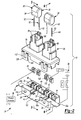
- a bused electrical center constructed in accordance with the teachings of the present disclosure is generally indicated by reference numeral 10. Except as described herein, the BEC 10 is generally conventional in its construction insofar as it houses a plurality of bus bars for supplying relatively high-current power to various circuits and conductors (e.g., wire harness 12, 14, 16, 18) in a modern automotive vehicle, such as a full hybrid electric vehicle (FHEV) or a plug-in hybrid electric vehicle (PHEV).
- FHEV full hybrid electric vehicle
- PHEV plug-in hybrid electric vehicle
- the BEC 10 can include a plurality of bus bars 20, a bus bar housing 22, one or more filter devices 24, a filter housing 26 and a plurality of interface terminals 28.
- Each of the bus bars 20 can be formed of an electrically conductive material, such as copper, and can be sized to transmit relatively high-current DC electric power.
- Each bus bar 20 can have a bus bar body 30 and one or more isolation tabs 32.
- the bus bars 20 are formed copper sheet and each isolation tab 32 is disposed generally perpendicular to its associated bus bar body 30.
- a first one of the bus bars 20a can be configured to be coupled to a vehicle electric system 34 that can include a power inverter 36 and a battery 38.
- Each of the other bus bars, such as bus bars 20b and 20c, can be coupled to the bus bar 20a via one of the filter devices 24.
- the bus bar housing 22 can include a first housing body 40, a plurality of first rails 42, a plurality of bus bar bosses 44 and a plurality of alignment bosses 45.
- the bus bar housing 22 is configured to at least partly house the bus bars 20 and in the example provided, the first housing body 40 is configured with structures, such as ribs and posts that are configured to interlock with the bus bars 20 such that the bus bars 20 nest into the first housing body 40.
- the first rails 42 can be coupled to and extend from the first housing body 40.
- Each of the isolation tabs 32 can be received between a pair of the first rails 42 and each pair of the first rails 42 can be interconnected by an end wall 46.
- the end wall and its associated first rails 42 can define a pocket 48.
- Each of the bus bar bosses 44 can be coupled to the first housing body 40 can be disposed in an associated pocket 48 between a pair of the first rails 42.
- Each of the alignment bosses 45 can extend from the first housing body 40 and can define a lead recess 45a. One or more edges 45b of the alignment bosses 45 can be chamfered.
- Each filter device 24 can comprise any means for electrically connecting the bus bar 20a to another one of the bus bars, such as bus bar 20b or 20c and for suppressing or canceling electrical "noise” that is received by the bus bar 20a (from the vehicle electric system 34) to thereby inhibit or reduce the transmission of the electrical "noise” to another one of the bus bars 20b, 20c.
- each filter device 24 comprises a capacitor 50 and a pair of leads 52.
- the capacitor 50 is conventional in its construction and operation and has an outer surface 54.
- the leads 52 can be formed of an electrically conductive wire material and are electrically coupled to the capacitor 50 in a conventional and well known manner.
- the leads 52 can be deformed to provide additional work hardening to a desired area and/or to change the cross-sectional area or surface area of a desired portion of the leads 52.
- the leads 52 comprise a deformed portion 60 that is deformed in a coining operation to provide additional work hardening of the deformed portion 60 (i.e., to provide added strength to the deformed portion 60), to change the cross-sectional area of wire that forms the deformed portion 60, and to provide the lead 52 with an insertion portion 62.
- the cross-sectional area of the wire can be changed in any desired manner, such as from round wire to a wire having a rectangular or square shape.
- the leads 52 can be initially formed of round wire having a nominal diameter of 1.0 mm and can be subsequently deformed such that the deformed portion 60 can have a rectangular cross-section having a length of 1.10 mm and a width of 0.80 mm.
- the undeformed portion 64 of the lead 52 can have a first cross-sectional shape and a first cross-sectional area, and that the deformed portion 60 of the lead 52 can have a second, different cross-sectional shape and a second cross-sectional area.
- the deformed portion 60 of the lead 52 is work hardened to a greater extent that the undeformed portion 64 that directly extends from the capacitor 50.
- the second cross-sectional area can be larger than the first cross-sectional area in some configurations.
- the insertion portion 62 can be configured with a tapering configuration and/or with reduced area to reduce the force that is needed to insert the leads 52 through the bus bar housing 22, the interface terminals 28 and into the filter housing 26.
- the insertion portion 62 of each of the leads 52 has a leading end that is chamfered on four sides.
- the filter housing 26 can have a second housing body 70, a plurality of second rails 72, and a plurality of guides 74.
- the second housing body 70 can define a filter cavity 80, a pair of lead apertures 82, and a filter device retainer 84.
- the filter cavity 80 is sized to at least partly receive the capacitor 50 and in the example provided, has a surface 88 that is configured to matingly engage a portion of the outer surface 54 of the capacitor 50.
- the lead apertures 82 are in communication with the filter cavity 80 and are sized to receive an associated one of the leads 52.
- the second housing body 70 defines a plurality of entry apertures 90, each of which interconnect an associated one of the lead apertures 82 to the filter cavity 80.
- each entry aperture 90 intersects the filter cavity 80 and an associated one of the lead apertures 82.
- Each entry aperture 90 can have a plurality of sidewalls 92 that can be tapered in a manner that converges with increasing distance from the filter cavity 80. Accordingly, it will be appreciated that the entry apertures 90 are configured to direct the insertion portion 62 of the leads 52 into the lead apertures 82 in the event that the insertion portions 62 contact one or more of the sidewalls 92.
- the filter device retainer 84 can comprise a pair of contoured spring arms 100 that can resiliently engage the outer surface 54 of the capacitor 50 and urge the capacitor 50 downwardly against the surface 88 of the filter cavity 80.
- the second rails 72 can be coupled to the second housing body 70 and can be disposed parallel to the lead apertures 82. Each of the guides 74 can be received between a pair of the second rails 72 such that the lead apertures 82 extend through the guides 74.
- the second housing body 70 can be coupled to the first housing body 40 in any desired manner such that the second rails 72 engage the first rails 42.
- the bus bar housing 22 includes a plurality of first retainers 110 that are coupled to the first housing body 40 and which engage with second retainers 112 that are coupled to the second housing body 70 to fixedly but removably couple the filter housing 26 to the bus bar housing 22.
- the first and second retainers 110 and 112 can be constructed in any desired manner.
- one of the first and second retainers 110 and 112 can comprise a protrusion having a ramped surface 120 and an abutting surface 122
- the other one of the first and second retainers 110 and 112 can comprise a generally U-shaped tab 124 having a tab member 126.
- contact between the ramped surfaces 120 and the U-shaped tabs 124 can deflect the tab members 126 outwardly so that the tab members 126 can ride over the ramped surfaces 120 and can engage the abutting surfaces 122 when the U-shaped tabs 124 return to an undeflected state.
- Each of the interface terminals 28 can be received in an associated one of the pockets 48 between a pair of the first rails 42 and can have a bus bar contact 130, which can be electrically coupled to a corresponding one of the isolation tabs 32, and a lead contact 132 that can be electrically coupled to a corresponding one of the leads 52.
- the bus bar contact 130 could be configured to both mechanically and electrically engage the corresponding one of the isolation tabs 32.
- the bus bar contact 130 could be configured with a receptacle-type terminal that is configured to mechanically and electrically engage one of the isolation tabs 32.
- the isolation tabs 32 can be male blade terminals that can mechanically and electrically engage a correspondingly configured terminal that is integrated into the bus bar contact 130.
- both the bus bar contact 130 and the lead contact 132 comprise flat, planar surfaces that are abutted against a corresponding one of the isolation tabs 32 and a contact zone 140 formed on at least a part of the deformed portion 60 a corresponding one of the leads 52. It will be appreciated that the contact zone 140 and the lead contact 132 can be shaped such that contact therebetween occurs over a predetermined area.
- Each of the interface terminals 28 can optionally include one or more spring arms or contacts that can be biased into contact with one or both of the isolation tabs 32 and the lead 52.
- a spring contact 150 can extend from the bus bar contact 130 and can include a generally U-shaped nose 152, the end or a side of which can be abutted to a flat surface of the lead 52 on an opposite side of the lead 52 that contacts the lead contact 132, and a generally L-shaped foot 154 that can be engaged to the isolation tab 32.
- the spring contact 150 can be elastically deformed or compressed between the lead 52 and the isolation tab 32 such that the lead 52 is biased into contact with the lead contact 132 and the isolation tab 32 is biased into contact with the bus bar contact 130.
- the guides 74 can extend from the second housing body 70 to an extent such that they are received into the interface terminals 28. Accordingly, it will be appreciated that the guides 74 can help position both the interface terminals 28 and the leads 52 relative to the filter housing 26.
- the alignment bosses 45 can extend from the first housing body 40 to an extent such that they are received into the interface terminals. Accordingly, it will be appreciated that the alignment bosses 45 can help to position both the interface terminals 28 and the leads 52 relative to the bus bar housing 22.
- the bus bars 20 can be assembled to the bus bar housing 22; the interface terminals 28 can be received into the pockets 48 and arranged relative to the bus bars 20 such that the bus bar contacts 130 abut the isolation tabs 32; the filter housing 26 can be assembled to the bus bar housing 22; and the filter devices 24 can be installed such that the outer surface 54 of the capacitors 50 is abutted against the surface 88 of the filter cavity 80, the filter device retainers 84 secures the capacitors 50 to the filter housing 24, and the leads 52 extend through the lead apertures 82, through the guides 74 and into the lead recesses 45a of the alignment bosses 45 such that the leads 52 are received in the alignment bosses 45.
- edges 45b of the alignment bosses 45 that surround the lead recesses 45a are tapered or contoured, the edges 45b can help to guide the insertion portions 62 into the lead recesses 45a.
- tapering or contouring of the outer edges 45b of the alignment bosses 45 can aid in the assembly of the terminal interfaces 28 into the pockets 48 (where the terminal interfaces 28 are installed over the alignment bosses 45).
- Example 1 relates to a bused electrical center comprising:
- Example 2 relates to the bused electrical center of Example 1, wherein each of the interface terminals comprises a spring contact that is compressed between the corresponding one of the isolation tabs and the corresponding one of the leads.
- Example 3 relates to the bused electrical center of Example 2, wherein the spring contact extends from the bus bar contact and includes a generally U-shaped nose, which is engaged to the corresponding one of the leads, and a generally L-shaped foot, which is engaged to the corresponding one of the isolation tabs.
- Example 4 relates to the bused electrical center of any of Examples 1 to 3, wherein each of the leads has a contact zone that contacts the lead contact of an associated one of the interface terminals and wherein the contact zone and the lead contact are shaped such that contact therebetween occurs over a predetermined area.
- Example 5 relates to the bused electrical center of Example 4, wherein the contact zones have a first flat surface that engages a flat surface formed on the lead contact.
- Example 6 relates to the bused electrical center of Example 5, wherein a second flat surface is formed on each contact zone on a side opposite the first flat surface and wherein each of the interface terminals includes a spring arm that engages second flat surface, the spring arm biasing the lead into abutment with the lead contact.
- Example 7 relates to the bused electrical center of any of Examples 1 to 6, wherein each of the leads has a leading end that is chamfered on four sides.
- Example 8 relates to the bused electrical center of any of Examples 1 to 7, wherein an end wall extends between and connects each adjacent pair of the first rails.
- Example 9 relates to the bused electrical center of any of Examples 1 to 8, wherein the bus bar housing further comprises a plurality of first retainers that are coupled to the first housing body, the first retainers being coupled to a plurality of second retainers that are coupled to the second housing body, wherein engagement of the first and second retainers to one another fixedly couples the bus bar housing to the filter housing.
- Example 10 relates to the bused electrical center of any of Examples 1 to 9, wherein each of the bus bars is nested into the first housing body of the bus bar housing.
- Example 11 relates to the bused electrical center of any of Examples 1 to 10, wherein the filter cavity is shaped to matingly engage a surface of the capacitor.
- Example 12 relates to the bused electrical center of any of Examples 1 to 11, wherein an entry aperture connects an associated one of the lead apertures to the filter cavity, the entry aperture intersecting the filter cavity and the associated one of the lead apertures, the entry aperture having sidewalls that are tapered in a manner that converges with increasing distance from the filter cavity.
- Example 13 relates to the bused electrical center of any of Examples 1 to 12, wherein the leads are formed of wire, wherein a first portion of the wire has a first cross-sectional shape, wherein a second portion of the wire has a second cross-sectional shape that is different from the first cross-sectional shape, wherein a contact zone is formed in at least a portion of the second portion of the wire, the contact zone contacting the lead contact of an associated one of the interface terminals.
- Example 14 relates to the bused electrical center of Example 13, wherein the first cross-sectional shape has a first area, wherein the second cross-sectional shape has a second area, and wherein the second area is larger than the first area.
- Example 15 relates to the bused electrical center of any of Examples 1 to 14, wherein each of the leads has a contact zone that contacts the lead contact of an associated one of the interface terminals, and wherein each of the leads is formed of a conductive material, and wherein the conductive material in the contact zone is work hardened to an extent that is greater than a portion of the lead that directly extends from the capacitor.
- Example 16 relates to a method for forming a bused electrical center, the method comprising:
- Example 17 relates to a method of Example 16, further comprising deforming the leads to form an insertion tip and a contact zone on each of the leads, wherein the insertion tip is received into the bus bar housing and wherein the contact zone contacts the associated one of the interface terminals to electrically couple the lead to the associated one of the interface terminals.
- Example 18 relates to a method of Example 17, wherein the leads are deformed in a coining operation.
Landscapes
- Engineering & Computer Science (AREA)
- Microelectronics & Electronic Packaging (AREA)
- Details Of Connecting Devices For Male And Female Coupling (AREA)
- Connecting Device With Holders (AREA)
- Connection Or Junction Boxes (AREA)
- Power Conversion In General (AREA)
- Multi-Conductor Connections (AREA)
Applications Claiming Priority (2)
| Application Number | Priority Date | Filing Date | Title |
|---|---|---|---|
| US201461937664P | 2014-02-10 | 2014-02-10 | |
| US14/601,654 US9444183B2 (en) | 2014-02-10 | 2015-01-21 | Bused electrical center for electric or hybrid electric vehicle |
Publications (3)
| Publication Number | Publication Date |
|---|---|
| EP2906028A2 true EP2906028A2 (fr) | 2015-08-12 |
| EP2906028A3 EP2906028A3 (fr) | 2015-11-25 |
| EP2906028B1 EP2906028B1 (fr) | 2017-06-07 |
Family
ID=52692350
Family Applications (1)
| Application Number | Title | Priority Date | Filing Date |
|---|---|---|---|
| EP15154268.5A Not-in-force EP2906028B1 (fr) | 2014-02-10 | 2015-02-09 | Centrale électrique pour véhicule électrique hybride ou électrique |
Country Status (3)
| Country | Link |
|---|---|
| US (1) | US9444183B2 (fr) |
| EP (1) | EP2906028B1 (fr) |
| JP (1) | JP5996009B2 (fr) |
Cited By (1)
| Publication number | Priority date | Publication date | Assignee | Title |
|---|---|---|---|---|
| EP3793339B1 (fr) * | 2019-09-13 | 2022-07-13 | Yazaki Corporation | Dispositif d'alimentation électrique embarqué |
Families Citing this family (12)
| Publication number | Priority date | Publication date | Assignee | Title |
|---|---|---|---|---|
| JP6349158B2 (ja) * | 2014-06-06 | 2018-06-27 | 矢崎総業株式会社 | 電気接続箱 |
| US10632856B2 (en) * | 2017-01-19 | 2020-04-28 | Ford Global Technologies, Llc | Connector-integrated endplate for battery electric vehicles |
| KR101940123B1 (ko) * | 2017-09-01 | 2019-01-18 | 주식회사 경신 | 차량용 전원분배장치 |
| US10181667B1 (en) * | 2018-05-29 | 2019-01-15 | Te Connectivity Corporation | Receptacle terminal for a junction box |
| KR101950298B1 (ko) * | 2018-12-20 | 2019-02-20 | 주식회사 경신 | 차량용 전원분배장치 |
| KR101959918B1 (ko) * | 2018-12-20 | 2019-03-19 | 주식회사 경신 | 차량용 전원분배장치 |
| KR101950297B1 (ko) * | 2018-12-20 | 2019-02-20 | 주식회사 경신 | 차량용 전원분배장치 |
| TWI722836B (zh) * | 2020-03-17 | 2021-03-21 | 群光電能科技股份有限公司 | 電源供應器的殼體 |
| CN113595377B (zh) * | 2020-04-30 | 2023-10-03 | 东电化电子(珠海)有限公司 | 汇流条和汇流条的用途 |
| DE102020111801A1 (de) | 2020-04-30 | 2021-11-04 | Tdk Electronics Ag | Sammelschiene |
| DE102020134688A1 (de) | 2020-12-22 | 2022-06-23 | Lisa Dräxlmaier GmbH | Multifunktionsträger und hochvolt-schütz für ein batteriesystem eines elektrischen fahrzeugs |
| JP7444082B2 (ja) * | 2021-01-08 | 2024-03-06 | 住友電装株式会社 | 電気接続箱 |
Family Cites Families (28)
| Publication number | Priority date | Publication date | Assignee | Title |
|---|---|---|---|---|
| JPS63248578A (ja) | 1987-04-03 | 1988-10-14 | Hitachi Ltd | 被覆線の超音波ボンデイング方法 |
| JP3156833B2 (ja) | 1995-09-22 | 2001-04-16 | 矢崎総業株式会社 | ブスバーへの電線接続方法 |
| JP3651216B2 (ja) * | 1997-12-15 | 2005-05-25 | 住友電装株式会社 | 分岐接続箱 |
| US6219245B1 (en) | 2000-04-18 | 2001-04-17 | General Motors Corporation | Electrically isolated power switching device mounting assembly for EMI reduction |
| JP4026044B2 (ja) | 2000-05-09 | 2007-12-26 | 株式会社デンソー | 基板接続部材 |
| JP2003087940A (ja) * | 2001-09-05 | 2003-03-20 | Auto Network Gijutsu Kenkyusho:Kk | 電気接続箱 |
| JP4013691B2 (ja) | 2002-07-31 | 2007-11-28 | 住友電装株式会社 | フレキシブルフラットケーブルの接続方法および超音波溶接機 |
| JP2005129389A (ja) * | 2003-10-24 | 2005-05-19 | Yazaki Corp | 中継端子 |
| JP4217669B2 (ja) * | 2004-08-04 | 2009-02-04 | 矢崎総業株式会社 | 高圧用電気接続箱 |
| JP2006296171A (ja) * | 2005-04-15 | 2006-10-26 | Yazaki Corp | 電気接続箱 |
| JP4464878B2 (ja) * | 2005-07-11 | 2010-05-19 | 矢崎総業株式会社 | 電気接続箱 |
| JP4916955B2 (ja) | 2007-06-07 | 2012-04-18 | 矢崎総業株式会社 | 電子部品内蔵ユニット |
| JP2009111832A (ja) | 2007-10-31 | 2009-05-21 | Yazaki Corp | ノイズフィルタ |
| JP5014092B2 (ja) | 2007-11-29 | 2012-08-29 | 矢崎総業株式会社 | 電子部品接続箱及び電子部品内蔵ユニット |
| JP5285997B2 (ja) | 2008-08-27 | 2013-09-11 | 矢崎総業株式会社 | 電源装置 |
| EP2332399B1 (fr) | 2008-08-29 | 2012-01-04 | Heyco, Inc. | Boîte de connexion pour des systèmes photovoltaïques |
| JP5371535B2 (ja) | 2009-04-24 | 2013-12-18 | 矢崎総業株式会社 | クランプ、及び電子部品内蔵ユニット |
| JP5443097B2 (ja) | 2009-08-18 | 2014-03-19 | 矢崎総業株式会社 | 電源装置 |
| JP5535567B2 (ja) * | 2009-10-01 | 2014-07-02 | 矢崎総業株式会社 | 電気接続箱の製造方法、電気接続箱、及びこの電気接続箱を備えた電源装置 |
| JP5437760B2 (ja) | 2009-10-01 | 2014-03-12 | 矢崎総業株式会社 | 電気接続箱及びこの電気接続箱を備えた電源装置 |
| JP5198522B2 (ja) | 2010-08-31 | 2013-05-15 | トヨタ自動車株式会社 | 蓄電装置および車両 |
| JP2012059658A (ja) | 2010-09-13 | 2012-03-22 | Auto Network Gijutsu Kenkyusho:Kk | バスバー |
| JP5609464B2 (ja) | 2010-09-14 | 2014-10-22 | 住友電装株式会社 | 電気接続箱 |
| JP5601259B2 (ja) | 2011-03-24 | 2014-10-08 | 住友電装株式会社 | 端子金具 |
| US8690588B2 (en) | 2011-12-20 | 2014-04-08 | Yazaki North America, Inc. | Junction box assembly having an over-travel spring |
| JP6070153B2 (ja) | 2012-12-18 | 2017-02-01 | 日産自動車株式会社 | 電源装置 |
| US9306381B2 (en) | 2013-11-15 | 2016-04-05 | Yazaki North America, Inc. | Electrical device having busbar with flexible weld crimp |
| US9722438B2 (en) | 2014-02-10 | 2017-08-01 | Yazaki North America, Inc. | Integrated power output service disconnect |
-
2015
- 2015-01-21 US US14/601,654 patent/US9444183B2/en active Active
- 2015-02-09 JP JP2015023360A patent/JP5996009B2/ja active Active
- 2015-02-09 EP EP15154268.5A patent/EP2906028B1/fr not_active Not-in-force
Non-Patent Citations (1)
| Title |
|---|
| None |
Cited By (1)
| Publication number | Priority date | Publication date | Assignee | Title |
|---|---|---|---|---|
| EP3793339B1 (fr) * | 2019-09-13 | 2022-07-13 | Yazaki Corporation | Dispositif d'alimentation électrique embarqué |
Also Published As
| Publication number | Publication date |
|---|---|
| US20150229071A1 (en) | 2015-08-13 |
| US9444183B2 (en) | 2016-09-13 |
| EP2906028B1 (fr) | 2017-06-07 |
| JP2015167225A (ja) | 2015-09-24 |
| JP5996009B2 (ja) | 2016-09-21 |
| EP2906028A3 (fr) | 2015-11-25 |
Similar Documents
| Publication | Publication Date | Title |
|---|---|---|
| EP2906028B1 (fr) | Centrale électrique pour véhicule électrique hybride ou électrique | |
| US10854860B2 (en) | Inter-battery connection device and inter-battery connection device assembly | |
| DE102006049652B4 (de) | Anschlussstück | |
| US20140045381A1 (en) | Joint connector | |
| EP2642607B1 (fr) | Dispositif de connexion électrique | |
| EP1732173A2 (fr) | Connecteur électrique | |
| CN107528133B (zh) | 电气汇流条连接器系统 | |
| JP2015167225A5 (fr) | ||
| EP3047542B1 (fr) | Connecteur de borne d'alimentation | |
| US10714860B2 (en) | Joint connector | |
| US9054508B2 (en) | Electrical junction box | |
| CN103579804A (zh) | 端子安装结构及用在该端子安装结构中的端子 | |
| US9780478B2 (en) | Connector and connection structure | |
| US9437946B2 (en) | Printed circuit board assembly having improved terminals | |
| EP1351346A1 (fr) | Connecteur de jonction pour faisceau de câbles | |
| US8507809B2 (en) | Component-equipped-holder mounting structure | |
| KR20100121950A (ko) | 조인트터미널이 구비된 커넥터 | |
| US20080032536A1 (en) | Plug-in connector | |
| JP2022505324A (ja) | 導電接続のためのソケットコンタクト素子 | |
| EP2696444A1 (fr) | Connecteur de raccordement | |
| US20140287629A1 (en) | Plug-type element | |
| EP1478052B1 (fr) | Terminal à contact à pression de denudage de gaines | |
| US20190341716A1 (en) | Joint connector | |
| KR20140129158A (ko) | 조인트 단자 및 조인트 커넥터 | |
| WO2013139871A1 (fr) | Connecteur femelle pour véhicule |
Legal Events
| Date | Code | Title | Description |
|---|---|---|---|
| PUAI | Public reference made under article 153(3) epc to a published international application that has entered the european phase |
Free format text: ORIGINAL CODE: 0009012 |
|
| 17P | Request for examination filed |
Effective date: 20150209 |
|
| AK | Designated contracting states |
Kind code of ref document: A2 Designated state(s): AL AT BE BG CH CY CZ DE DK EE ES FI FR GB GR HR HU IE IS IT LI LT LU LV MC MK MT NL NO PL PT RO RS SE SI SK SM TR |
|
| AX | Request for extension of the european patent |
Extension state: BA ME |
|
| PUAL | Search report despatched |
Free format text: ORIGINAL CODE: 0009013 |
|
| AK | Designated contracting states |
Kind code of ref document: A3 Designated state(s): AL AT BE BG CH CY CZ DE DK EE ES FI FR GB GR HR HU IE IS IT LI LT LU LV MC MK MT NL NO PL PT RO RS SE SI SK SM TR |
|
| AX | Request for extension of the european patent |
Extension state: BA ME |
|
| RIC1 | Information provided on ipc code assigned before grant |
Ipc: H05K 7/02 20060101AFI20151022BHEP |
|
| GRAP | Despatch of communication of intention to grant a patent |
Free format text: ORIGINAL CODE: EPIDOSNIGR1 |
|
| INTG | Intention to grant announced |
Effective date: 20170130 |
|
| GRAS | Grant fee paid |
Free format text: ORIGINAL CODE: EPIDOSNIGR3 |
|
| AK | Designated contracting states |
Kind code of ref document: B1 Designated state(s): AL AT BE BG CH CY CZ DE DK EE ES FI FR GB GR HR HU IE IS IT LI LT LU LV MC MK MT NL NO PL PT RO RS SE SI SK SM TR |
|
| REG | Reference to a national code |
Ref country code: GB Ref legal event code: FG4D |
|
| GRAA | (expected) grant |
Free format text: ORIGINAL CODE: 0009210 |
|
| REG | Reference to a national code |
Ref country code: CH Ref legal event code: EP Ref country code: AT Ref legal event code: REF Ref document number: 900096 Country of ref document: AT Kind code of ref document: T Effective date: 20170615 |
|
| REG | Reference to a national code |
Ref country code: IE Ref legal event code: FG4D |
|
| REG | Reference to a national code |
Ref country code: DE Ref legal event code: R096 Ref document number: 602015002948 Country of ref document: DE |
|
| REG | Reference to a national code |
Ref country code: NL Ref legal event code: MP Effective date: 20170607 |
|
| REG | Reference to a national code |
Ref country code: LT Ref legal event code: MG4D |
|
| PG25 | Lapsed in a contracting state [announced via postgrant information from national office to epo] |
Ref country code: NO Free format text: LAPSE BECAUSE OF FAILURE TO SUBMIT A TRANSLATION OF THE DESCRIPTION OR TO PAY THE FEE WITHIN THE PRESCRIBED TIME-LIMIT Effective date: 20170907 Ref country code: GR Free format text: LAPSE BECAUSE OF FAILURE TO SUBMIT A TRANSLATION OF THE DESCRIPTION OR TO PAY THE FEE WITHIN THE PRESCRIBED TIME-LIMIT Effective date: 20170908 Ref country code: LT Free format text: LAPSE BECAUSE OF FAILURE TO SUBMIT A TRANSLATION OF THE DESCRIPTION OR TO PAY THE FEE WITHIN THE PRESCRIBED TIME-LIMIT Effective date: 20170607 Ref country code: HR Free format text: LAPSE BECAUSE OF FAILURE TO SUBMIT A TRANSLATION OF THE DESCRIPTION OR TO PAY THE FEE WITHIN THE PRESCRIBED TIME-LIMIT Effective date: 20170607 Ref country code: ES Free format text: LAPSE BECAUSE OF FAILURE TO SUBMIT A TRANSLATION OF THE DESCRIPTION OR TO PAY THE FEE WITHIN THE PRESCRIBED TIME-LIMIT Effective date: 20170607 Ref country code: FI Free format text: LAPSE BECAUSE OF FAILURE TO SUBMIT A TRANSLATION OF THE DESCRIPTION OR TO PAY THE FEE WITHIN THE PRESCRIBED TIME-LIMIT Effective date: 20170607 |
|
| REG | Reference to a national code |
Ref country code: AT Ref legal event code: MK05 Ref document number: 900096 Country of ref document: AT Kind code of ref document: T Effective date: 20170607 |
|
| PG25 | Lapsed in a contracting state [announced via postgrant information from national office to epo] |
Ref country code: NL Free format text: LAPSE BECAUSE OF FAILURE TO SUBMIT A TRANSLATION OF THE DESCRIPTION OR TO PAY THE FEE WITHIN THE PRESCRIBED TIME-LIMIT Effective date: 20170607 Ref country code: SE Free format text: LAPSE BECAUSE OF FAILURE TO SUBMIT A TRANSLATION OF THE DESCRIPTION OR TO PAY THE FEE WITHIN THE PRESCRIBED TIME-LIMIT Effective date: 20170607 Ref country code: BG Free format text: LAPSE BECAUSE OF FAILURE TO SUBMIT A TRANSLATION OF THE DESCRIPTION OR TO PAY THE FEE WITHIN THE PRESCRIBED TIME-LIMIT Effective date: 20170907 Ref country code: RS Free format text: LAPSE BECAUSE OF FAILURE TO SUBMIT A TRANSLATION OF THE DESCRIPTION OR TO PAY THE FEE WITHIN THE PRESCRIBED TIME-LIMIT Effective date: 20170607 Ref country code: LV Free format text: LAPSE BECAUSE OF FAILURE TO SUBMIT A TRANSLATION OF THE DESCRIPTION OR TO PAY THE FEE WITHIN THE PRESCRIBED TIME-LIMIT Effective date: 20170607 |
|
| PG25 | Lapsed in a contracting state [announced via postgrant information from national office to epo] |
Ref country code: AT Free format text: LAPSE BECAUSE OF FAILURE TO SUBMIT A TRANSLATION OF THE DESCRIPTION OR TO PAY THE FEE WITHIN THE PRESCRIBED TIME-LIMIT Effective date: 20170607 Ref country code: CZ Free format text: LAPSE BECAUSE OF FAILURE TO SUBMIT A TRANSLATION OF THE DESCRIPTION OR TO PAY THE FEE WITHIN THE PRESCRIBED TIME-LIMIT Effective date: 20170607 Ref country code: EE Free format text: LAPSE BECAUSE OF FAILURE TO SUBMIT A TRANSLATION OF THE DESCRIPTION OR TO PAY THE FEE WITHIN THE PRESCRIBED TIME-LIMIT Effective date: 20170607 Ref country code: RO Free format text: LAPSE BECAUSE OF FAILURE TO SUBMIT A TRANSLATION OF THE DESCRIPTION OR TO PAY THE FEE WITHIN THE PRESCRIBED TIME-LIMIT Effective date: 20170607 Ref country code: SK Free format text: LAPSE BECAUSE OF FAILURE TO SUBMIT A TRANSLATION OF THE DESCRIPTION OR TO PAY THE FEE WITHIN THE PRESCRIBED TIME-LIMIT Effective date: 20170607 |
|
| PG25 | Lapsed in a contracting state [announced via postgrant information from national office to epo] |
Ref country code: IS Free format text: LAPSE BECAUSE OF FAILURE TO SUBMIT A TRANSLATION OF THE DESCRIPTION OR TO PAY THE FEE WITHIN THE PRESCRIBED TIME-LIMIT Effective date: 20171007 Ref country code: PL Free format text: LAPSE BECAUSE OF FAILURE TO SUBMIT A TRANSLATION OF THE DESCRIPTION OR TO PAY THE FEE WITHIN THE PRESCRIBED TIME-LIMIT Effective date: 20170607 Ref country code: SM Free format text: LAPSE BECAUSE OF FAILURE TO SUBMIT A TRANSLATION OF THE DESCRIPTION OR TO PAY THE FEE WITHIN THE PRESCRIBED TIME-LIMIT Effective date: 20170607 Ref country code: IT Free format text: LAPSE BECAUSE OF FAILURE TO SUBMIT A TRANSLATION OF THE DESCRIPTION OR TO PAY THE FEE WITHIN THE PRESCRIBED TIME-LIMIT Effective date: 20170607 |
|
| REG | Reference to a national code |
Ref country code: DE Ref legal event code: R097 Ref document number: 602015002948 Country of ref document: DE |
|
| PLBE | No opposition filed within time limit |
Free format text: ORIGINAL CODE: 0009261 |
|
| STAA | Information on the status of an ep patent application or granted ep patent |
Free format text: STATUS: NO OPPOSITION FILED WITHIN TIME LIMIT |
|
| PG25 | Lapsed in a contracting state [announced via postgrant information from national office to epo] |
Ref country code: DK Free format text: LAPSE BECAUSE OF FAILURE TO SUBMIT A TRANSLATION OF THE DESCRIPTION OR TO PAY THE FEE WITHIN THE PRESCRIBED TIME-LIMIT Effective date: 20170607 |
|
| 26N | No opposition filed |
Effective date: 20180308 |
|
| PG25 | Lapsed in a contracting state [announced via postgrant information from national office to epo] |
Ref country code: SI Free format text: LAPSE BECAUSE OF FAILURE TO SUBMIT A TRANSLATION OF THE DESCRIPTION OR TO PAY THE FEE WITHIN THE PRESCRIBED TIME-LIMIT Effective date: 20170607 |
|
| REG | Reference to a national code |
Ref country code: CH Ref legal event code: PL |
|
| PG25 | Lapsed in a contracting state [announced via postgrant information from national office to epo] |
Ref country code: MC Free format text: LAPSE BECAUSE OF FAILURE TO SUBMIT A TRANSLATION OF THE DESCRIPTION OR TO PAY THE FEE WITHIN THE PRESCRIBED TIME-LIMIT Effective date: 20170607 |
|
| REG | Reference to a national code |
Ref country code: IE Ref legal event code: MM4A |
|
| REG | Reference to a national code |
Ref country code: BE Ref legal event code: MM Effective date: 20180228 |
|
| PG25 | Lapsed in a contracting state [announced via postgrant information from national office to epo] |
Ref country code: LU Free format text: LAPSE BECAUSE OF NON-PAYMENT OF DUE FEES Effective date: 20180209 Ref country code: CH Free format text: LAPSE BECAUSE OF NON-PAYMENT OF DUE FEES Effective date: 20180228 Ref country code: LI Free format text: LAPSE BECAUSE OF NON-PAYMENT OF DUE FEES Effective date: 20180228 |
|
| REG | Reference to a national code |
Ref country code: FR Ref legal event code: ST Effective date: 20181031 |
|
| PG25 | Lapsed in a contracting state [announced via postgrant information from national office to epo] |
Ref country code: IE Free format text: LAPSE BECAUSE OF NON-PAYMENT OF DUE FEES Effective date: 20180209 |
|
| PG25 | Lapsed in a contracting state [announced via postgrant information from national office to epo] |
Ref country code: BE Free format text: LAPSE BECAUSE OF NON-PAYMENT OF DUE FEES Effective date: 20180228 Ref country code: FR Free format text: LAPSE BECAUSE OF NON-PAYMENT OF DUE FEES Effective date: 20180228 |
|
| PGFP | Annual fee paid to national office [announced via postgrant information from national office to epo] |
Ref country code: DE Payment date: 20190429 Year of fee payment: 5 |
|
| GBPC | Gb: european patent ceased through non-payment of renewal fee |
Effective date: 20190209 |
|
| PG25 | Lapsed in a contracting state [announced via postgrant information from national office to epo] |
Ref country code: MT Free format text: LAPSE BECAUSE OF NON-PAYMENT OF DUE FEES Effective date: 20180209 Ref country code: GB Free format text: LAPSE BECAUSE OF NON-PAYMENT OF DUE FEES Effective date: 20190209 |
|
| PG25 | Lapsed in a contracting state [announced via postgrant information from national office to epo] |
Ref country code: TR Free format text: LAPSE BECAUSE OF FAILURE TO SUBMIT A TRANSLATION OF THE DESCRIPTION OR TO PAY THE FEE WITHIN THE PRESCRIBED TIME-LIMIT Effective date: 20170607 |
|
| PG25 | Lapsed in a contracting state [announced via postgrant information from national office to epo] |
Ref country code: PT Free format text: LAPSE BECAUSE OF FAILURE TO SUBMIT A TRANSLATION OF THE DESCRIPTION OR TO PAY THE FEE WITHIN THE PRESCRIBED TIME-LIMIT Effective date: 20170607 |
|
| PG25 | Lapsed in a contracting state [announced via postgrant information from national office to epo] |
Ref country code: HU Free format text: LAPSE BECAUSE OF FAILURE TO SUBMIT A TRANSLATION OF THE DESCRIPTION OR TO PAY THE FEE WITHIN THE PRESCRIBED TIME-LIMIT; INVALID AB INITIO Effective date: 20150209 Ref country code: MK Free format text: LAPSE BECAUSE OF NON-PAYMENT OF DUE FEES Effective date: 20170607 Ref country code: CY Free format text: LAPSE BECAUSE OF FAILURE TO SUBMIT A TRANSLATION OF THE DESCRIPTION OR TO PAY THE FEE WITHIN THE PRESCRIBED TIME-LIMIT Effective date: 20170607 |
|
| PG25 | Lapsed in a contracting state [announced via postgrant information from national office to epo] |
Ref country code: AL Free format text: LAPSE BECAUSE OF FAILURE TO SUBMIT A TRANSLATION OF THE DESCRIPTION OR TO PAY THE FEE WITHIN THE PRESCRIBED TIME-LIMIT Effective date: 20170607 |
|
| REG | Reference to a national code |
Ref country code: DE Ref legal event code: R119 Ref document number: 602015002948 Country of ref document: DE |
|
| PG25 | Lapsed in a contracting state [announced via postgrant information from national office to epo] |
Ref country code: DE Free format text: LAPSE BECAUSE OF NON-PAYMENT OF DUE FEES Effective date: 20200901 |
|
| P01 | Opt-out of the competence of the unified patent court (upc) registered |
Effective date: 20230703 |