EP2902580A1 - Teleskopschiebetüranlage - Google Patents
Teleskopschiebetüranlage Download PDFInfo
- Publication number
- EP2902580A1 EP2902580A1 EP15152854.4A EP15152854A EP2902580A1 EP 2902580 A1 EP2902580 A1 EP 2902580A1 EP 15152854 A EP15152854 A EP 15152854A EP 2902580 A1 EP2902580 A1 EP 2902580A1
- Authority
- EP
- European Patent Office
- Prior art keywords
- door
- run
- telescopic sliding
- track
- door leaf
- Prior art date
- Legal status (The legal status is an assumption and is not a legal conclusion. Google has not performed a legal analysis and makes no representation as to the accuracy of the status listed.)
- Granted
Links
- 238000000034 method Methods 0.000 description 7
- 230000008878 coupling Effects 0.000 description 4
- 238000010168 coupling process Methods 0.000 description 4
- 238000005859 coupling reaction Methods 0.000 description 4
- 239000011521 glass Substances 0.000 description 2
- 238000010009 beating Methods 0.000 description 1
- 238000010276 construction Methods 0.000 description 1
- 238000013016 damping Methods 0.000 description 1
- 238000012423 maintenance Methods 0.000 description 1
Images


Classifications
-
- E—FIXED CONSTRUCTIONS
- E05—LOCKS; KEYS; WINDOW OR DOOR FITTINGS; SAFES
- E05F—DEVICES FOR MOVING WINGS INTO OPEN OR CLOSED POSITION; CHECKS FOR WINGS; WING FITTINGS NOT OTHERWISE PROVIDED FOR, CONCERNED WITH THE FUNCTIONING OF THE WING
- E05F15/00—Power-operated mechanisms for wings
- E05F15/60—Power-operated mechanisms for wings using electrical actuators
- E05F15/603—Power-operated mechanisms for wings using electrical actuators using rotary electromotors
- E05F15/632—Power-operated mechanisms for wings using electrical actuators using rotary electromotors for horizontally-sliding wings
- E05F15/643—Power-operated mechanisms for wings using electrical actuators using rotary electromotors for horizontally-sliding wings operated by flexible elongated pulling elements, e.g. belts, chains or cables
-
- E—FIXED CONSTRUCTIONS
- E05—LOCKS; KEYS; WINDOW OR DOOR FITTINGS; SAFES
- E05D—HINGES OR SUSPENSION DEVICES FOR DOORS, WINDOWS OR WINGS
- E05D15/00—Suspension arrangements for wings
- E05D15/06—Suspension arrangements for wings for wings sliding horizontally more or less in their own plane
- E05D15/08—Suspension arrangements for wings for wings sliding horizontally more or less in their own plane consisting of two or more independent parts movable each in its own guides
-
- E—FIXED CONSTRUCTIONS
- E05—LOCKS; KEYS; WINDOW OR DOOR FITTINGS; SAFES
- E05F—DEVICES FOR MOVING WINGS INTO OPEN OR CLOSED POSITION; CHECKS FOR WINGS; WING FITTINGS NOT OTHERWISE PROVIDED FOR, CONCERNED WITH THE FUNCTIONING OF THE WING
- E05F1/00—Closers or openers for wings, not otherwise provided for in this subclass
- E05F1/08—Closers or openers for wings, not otherwise provided for in this subclass spring-actuated, e.g. for horizontally sliding wings
- E05F1/16—Closers or openers for wings, not otherwise provided for in this subclass spring-actuated, e.g. for horizontally sliding wings for sliding wings
-
- E—FIXED CONSTRUCTIONS
- E05—LOCKS; KEYS; WINDOW OR DOOR FITTINGS; SAFES
- E05F—DEVICES FOR MOVING WINGS INTO OPEN OR CLOSED POSITION; CHECKS FOR WINGS; WING FITTINGS NOT OTHERWISE PROVIDED FOR, CONCERNED WITH THE FUNCTIONING OF THE WING
- E05F17/00—Special devices for shifting a plurality of wings operated simultaneously
- E05F17/004—Special devices for shifting a plurality of wings operated simultaneously for wings which abut when closed
-
- E—FIXED CONSTRUCTIONS
- E05—LOCKS; KEYS; WINDOW OR DOOR FITTINGS; SAFES
- E05Y—INDEXING SCHEME ASSOCIATED WITH SUBCLASSES E05D AND E05F, RELATING TO CONSTRUCTION ELEMENTS, ELECTRIC CONTROL, POWER SUPPLY, POWER SIGNAL OR TRANSMISSION, USER INTERFACES, MOUNTING OR COUPLING, DETAILS, ACCESSORIES, AUXILIARY OPERATIONS NOT OTHERWISE PROVIDED FOR, APPLICATION THEREOF
- E05Y2800/00—Details, accessories and auxiliary operations not otherwise provided for
- E05Y2800/10—Additional functions
- E05Y2800/122—Telescopic action
-
- E—FIXED CONSTRUCTIONS
- E05—LOCKS; KEYS; WINDOW OR DOOR FITTINGS; SAFES
- E05Y—INDEXING SCHEME ASSOCIATED WITH SUBCLASSES E05D AND E05F, RELATING TO CONSTRUCTION ELEMENTS, ELECTRIC CONTROL, POWER SUPPLY, POWER SIGNAL OR TRANSMISSION, USER INTERFACES, MOUNTING OR COUPLING, DETAILS, ACCESSORIES, AUXILIARY OPERATIONS NOT OTHERWISE PROVIDED FOR, APPLICATION THEREOF
- E05Y2800/00—Details, accessories and auxiliary operations not otherwise provided for
- E05Y2800/20—Combinations of elements
- E05Y2800/21—Combinations of elements of identical elements, e.g. of identical compression springs
-
- E—FIXED CONSTRUCTIONS
- E05—LOCKS; KEYS; WINDOW OR DOOR FITTINGS; SAFES
- E05Y—INDEXING SCHEME ASSOCIATED WITH SUBCLASSES E05D AND E05F, RELATING TO CONSTRUCTION ELEMENTS, ELECTRIC CONTROL, POWER SUPPLY, POWER SIGNAL OR TRANSMISSION, USER INTERFACES, MOUNTING OR COUPLING, DETAILS, ACCESSORIES, AUXILIARY OPERATIONS NOT OTHERWISE PROVIDED FOR, APPLICATION THEREOF
- E05Y2800/00—Details, accessories and auxiliary operations not otherwise provided for
- E05Y2800/20—Combinations of elements
- E05Y2800/23—Combinations of elements of elements of different categories
- E05Y2800/24—Combinations of elements of elements of different categories of springs and brakes
Definitions
- the present invention relates to a telescopic sliding door system having at least a first and a second door leaf, wherein the second door leaf is coupled to the first door wing for carrying out a rectified movement and is drivable via the first door leaf.
- a telescopic sliding door system which has a running rail device, each with at least one running rail for each door leaf, wherein the door wings are each guided over at least one drive in the track rail.
- the previously known telescopic sliding door system has a toothed belt drive, wherein the first and second door leaves are connected via the toothed belt drive.
- the toothed belt drive of the prior art telescoping sliding door system is located above the track rail and horizontally disposed (i.e., the toothed pulleys of the toothed belt drive have vertical axes of rotation), thereby making the track assembly very high and very wide.
- the prior art telescopic sliding door system on rails which have two opposing tracks for the drives of the door. Therefore, the assembly of the prior art telescopic sliding door system is relatively complicated and it is very expensive to get to the inside of the track for maintenance purposes.
- the invention is defined by the features of claim 1.
- the telescopic sliding door system has at least one first and one second door leaf, wherein the second door leaf is coupled to the first door leaf for carrying out a rectified movement and can be driven via the first door leaf.
- the telescopic sliding door system has a running rail device, each with at least one running rail for each door, wherein the door wings are each guided over at least one drive in the track rail.
- a traction drive with a first strand and a second strand connects the first and the second door.
- the invention is characterized in that the first strand runs above the second strand and the traction mechanism is guided over a deflection device arranged on the second door leaf.
- the first strand may be fixed in position relative to the first and the second door and the second strand may be connected to the first door.
- the second run can be fixed in relation to the first and the second door and the first run can be connected to the first door.
- the telescopic sliding door system is described on the basis of the directional information "longitudinal direction", "width direction” and "height direction".
- the longitudinal direction corresponds to the direction that predetermine the door during the opening or closing movement.
- the length of the telescopic sliding door system is also the extension in the longitudinal direction.
- the width direction is the direction orthogonal to the longitudinal direction in the same horizontal plane.
- the width is the extension of the telescopic sliding door system in the width direction.
- the height direction is orthogonal to the longitudinal direction in the same vertical plane, the height being an extension of the telescopic sliding door system in the height direction.
- the rail device Due to the arrangement of the traction mechanism drive such that the first strand runs above the second strand, a very narrow arrangement of the traction mechanism drive in the width direction is possible.
- the rail device may be formed with a relatively small width, whereby a compact design of the rail device is possible.
- the telescopic sliding door system according to the invention can be designed in an aesthetically pleasing manner, since the rail device by a compact design for the viewer acts inconspicuously.
- the width of the rail device is thus determined essentially by the distance between the first and second door in the width direction and thus the space requirement of the drives in this direction and not by the width of the traction drive.
- the inventive design of the traction mechanism ensures that the second door is driven by the first door.
- the user only has to move the first door and the second door is automatically carried in the same direction.
- the transmitted from the first door to the second door leaf movement is reduced by means of the traction mechanism, so that the second door is moved at a different speed from the first door.
- the second door leaf moves at half the speed of the first door leaf.
- the door leaves can be, for example, glass door leaves.
- first and the second run are arranged in a longitudinally extending vertical plane.
- the deflection device for example deflection rollers, can also be arranged very compactly in this plane and thus in relation to the width direction of the running rail device.
- the traction mechanism can in particular have a cable.
- the second strand is arranged in the horizontal direction (width direction) next to the second door leaf.
- the second run runs in front of the second door leaf and thus between the first and the second door leaf.
- the plane in which the first and the second run runs is arranged in front of the second door leaf and thus between the first and the second door leaf.
- the running rail device in which usually the traction mechanism is arranged to cover this, also be designed to be relatively compact in their height. Since the door panels usually extend partially into the track device, the second track can be arranged adjacent to the part of the second door wing extending into the track device.
- the rail device compared to conventional rail devices that are used for sliding door systems without traction drive, not or only slightly higher designed.
- a telescopic sliding door system can be created with an aesthetically pleasing track device.
- the second run in the suspended state of the second door is advantageously accessible from the longitudinal side, so that the second strand, for example, for connection to the first door is achieved in an advantageous manner.
- the deflection device consists of two deflection devices, which are preferably each arranged on a drive of the second door leaf. This ensures that the deflection devices are carried along in the movement of the second door in an advantageous manner and the desired movement of the second door leaf is achieved in relation to the first door leaf.
- the deflection device has an arm on which one of the deflection devices is arranged, wherein the arm projects in the longitudinal direction of the rail device via the second door in the direction of the closed position of the door.
- an arm is arranged on the first door, which projects in the longitudinal direction over the first door in the opening direction, being connected via the arm of the first door with the first and second run. Also, this can be achieved that no or only a slight overlap of the first and second door leaf in the closed position is necessary.
- the strand of the traction mechanism drive fastened in a stationary manner relative to the first and the second door leaf is fastened in the running rail device via a fastening device.
- the run can be fixed in a particularly simple manner against the first and the second door leaf.
- the fastening device has a Buchstoffspannvorraum, about which the desired voltage of the traction means of the traction drive can be adjusted.
- the Switzerlandstoffspannvorraum may have a spring means, whereby, for example, in the height adjustment of the door, a slight elongation of the traction means is possible.
- the fastening device is slidably mounted in the longitudinal direction of the running rail device and / or is attached to the running rail of the second door leaf. Due to the displaceable arrangement of the fastening device in the rail device it can be moved during assembly before the final attachment, so that an adjustment of the traction mechanism during assembly in a simple manner is possible.
- the first door leaf may have a door leaf which has smaller dimensions in the vertical direction (height direction) than the door leaf of the second door leaf. It can thereby be achieved that the upper edge of the first door leaf extends below the second run, so that the second run can be reached in a particularly advantageous manner from the longitudinal side of the running rail. As a result, for example, a connection of the second run with the first door during assembly in a simple manner.
- a cable coupler can be mounted on the upper edge of the door leaf of the first door leaf. The cable coupler may also be part of a drive of the first door leaf.
- the track device has a first track for the first door and a second track for the second door, wherein the first and the second track rail are mounted separately.
- the telescopic sliding door system according to the invention can be mounted in a very simple manner, for example by first fixing the second running rail for the second door leaf at the desired location. Thereafter, the second door can be hung in the second track and the traction mechanism can be mounted.
- the traction mechanism is already attached via the deflection device to the second door.
- the second running rail is first mounted without the first running rail, the second running rail is freely accessible from the longitudinal side, so that not only the mounting of the second door leaf is possible, but also, for example, the mounting of the fastening device for a run of the traction mechanism drive. Then the first track can be mounted and the first door can be hung.
- a connection of the first door leaf with the second strand can be done for example via a Switzerlandstoffkoppler.
- the design of the running rail device consisting of a first and a second running rail, which can be mounted separately, can also be realized independently of the configuration of the traction mechanism drive.
- the invention thus also relates to a telescopic sliding door system having at least a first and a second door and a running rail device, each with at least one rail for each door, said door are each guided via at least one drive in the track rail, wherein the running rail device is a first track for having the first door and a second track for the second door, wherein the first and the second track rail are mounted separately. It can be provided that the second door is coupled to the first door for performing a rectified movement and can be driven via the first door.
- the first and the second track each have a track for guiding the drives of the door, wherein the first track has an access opening to the guide path, the rectified to an access opening to the guide rail of second Running track is.
- the access opening to the guide track of the first track rail is on the side facing away from the second track rail side of the first track.
- a damper unit with a pull-in function is provided, which initially brakes the first door leaf when moving in the direction of an end position and subsequently drives it into the end position. This ensures a smooth retraction of the first door leaf in the end position.
- the telescopic sliding door system may include a damper unit with retraction function, which first decelerates the second door during the process in the direction of an end position and then drives into the end position. This prevents that any kinetic energy remains in the process of the second door leaf in its end position, which is transmitted from the second door to the traction drive and this can load or damage. Furthermore, it is prevented that the second door leaf moves during the process in its end position due to a kinetic energy beyond this end position and is damaged by the abutment against an obstacle.
- damper units each with pull-in function are provided for each door leaf.
- a damper unit is in each case arranged at the end position representing the end position of the respective door leaf and a damper unit at the closed position representing the end position of the respective door leaf. This will ensures that neither of the door leaves moves beyond the respective end position during the opening and closing movement and is damaged. In addition, there is a slow retraction into the end position.
- a limiting device delimiting the travel path of the respective door leaf is arranged on each damper unit.
- the travel path of each door leaf is limited in an end position and it is ensured that the respective door leaf can possibly strike at the limiting device, whereby damage to the door leaf is avoided.
- the limiting device that takes place in the process of a door leaf in an end position defined abutment on the limiting device, so that a beating within the damper units is avoided, whereby damage to the damper units are prevented.
- a damper unit with pull-in function for the second door leaf which initially decelerates the second door leaf during the process towards an end position and then drives it into the end position, can also be realized independently of the specific design of the traction mechanism drive.
- the invention therefore also relates to a telescopic sliding door system having at least a first and a second door, wherein the second door is coupled to the first door for performing a rectified movement and is drivable via the first door, in which a damper unit is provided with catchment function, the second door during the process in the direction of an end position first decelerates and then drives into the end position.
- a damper unit is provided with catchment function, the second door during the process in the direction of an end position first decelerates and then drives into the end position.
- one or more damper units is provided with pull-in function for the first door leaf or are.
- damper units are provided with pull-in function, in each case two damper units are provided for each door and each a damper unit acting on the closed position end position of the respective door leaf and a damper unit acting on the open position end position of the respective door leaf.
- a telescopic sliding door system with a damper unit with retraction function which initially slows down the second door when moving towards an end position and then drives into the end position, may also have a track device, each with a track for each door, the door each having at least one drive in the Run rail are guided. It can be provided that the track device has a first track for the first door and a second track for the second door, wherein the first and the second track are mounted separately.
- the first and the second track rail can each have a guide track for guiding the drives of the door leaves, wherein the first track rail has an access opening to the guide track, which is rectified to an access opening to the guide track of the second track rail.
- a telescopic sliding door system 1 according to the invention is shown schematically in a perspective view.
- the telescopic sliding door system 1 has a first door 3 and a second door 5.
- the door leaves are guided in a running rail device 7.
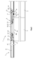
- FIG. 2 in which a view is shown on the longitudinal side of a telescopic sliding door 1 according to the invention, it can be seen, the second door leaf 5 is coupled to the first door leaf 3, so that both door leaves can perform a rectified movement.
- the second door 5 is drivable on the first door 3.
- the second door 5 is connected via a traction mechanism 9 with the first door 3.
- the traction mechanism drive has a first run 9a and a second run 9b, wherein the first run 9a extends above the second run 9b.
- the first strand 9a and the second strand 9b are formed by a traction means 9c of the traction mechanism 9.
- the traction mechanism 9 may be formed, for example, as a cable, so that the traction means 9c is a rope.
- the upper run 9a is attached via a fastening device 11 to the running rail device 7 and thus fixed in relation to the first and the second door leaf.
- About a Switzerlandstoffkoppler 13 of the first door 3 is connected to the second run 9b.
- a deflection device 15 which consists of two deflection devices 15a and 15b.
- the deflection devices deflect the traction means 9c of the traction mechanism drive 9, so that a closed circulation of the traction means 9c results.
- the deflection devices 15a and 15b each have two deflection rollers 17.
- the pulleys are arranged vertically and have an axis of rotation in the horizontal direction, so that the first and the second run 9a and 9b extend in a common vertical plane.
- the second door 5 has two drives 19, over which the door 5 is guided in the rail device 7.
- the deflection devices 15 a and 15 b are each arranged on one of the drives 19.
- the deflecting device 15a is arranged on an arm 21 which protrudes beyond the door leaf 5 in the longitudinal direction of the running rail device 7 and in the direction of the closed position of the door leaf 5. This ensures that in the in Fig. 2 shown closed position the deflecting device 15a and parts of the cable 9c are located above the first door leaf 3 or from the drive 19, over which the door leaf 3 is guided in the rail device 7, is covered. This ensures that a coupling via the cable coupler 13 to the second run 9b is ensured even in the fully closed position of the telescopic sliding door system.
- the fastening device 11 which may also comprise a traction device, via which the traction means 9c to the desired voltage can be brought, is slidably mounted in the rail device in the longitudinal direction.
- the fastening device in the assembly of the second door leaf 5 and the traction mechanism 9 can be adjusted in a simple manner.
- the track device 7 consists of a first track 21 for the first door 3, a second track 23 for the second door 5 and a shutter 25 which is fixed to the first track 21, and the first and the second track 21,23 concealed.
- the first and the second rail 21,23 each have a guide track 27 for guiding the drives 19 of the first and the second door leaf 3,5.
- the first track 21 has an access opening 21a, which is arranged rectified to an access opening 23a to the guide track 27 of the second track rail 23.
- the access opening 21a is thus located on the side facing away from the second running rail 23 side of the first track rail 21.
- the first and second door leaves 3.5 can be in the in Fig. 4 illustrated embodiment in each case from the right side, the longitudinal side, hang in the running rail device 7.
- the first and second runners 21, 23 can be mounted separately from one another. In this way, first, the second track 23 can be attached to the desired location. Subsequently, the second door 5 is mounted together with the attached to the second door 5 traction drive 9 in the second track 23 by the drive 19 engages in the guide track 27. Subsequently, the first running rail 21 is attached to the second running rail 23. The first door 3 can now be suspended via a drive 19 in the first track 21, wherein the drive 19 engages in the guide track 27.
- the door leaf of the door leaf 3 is connected via a holding device 29 with the drive 19. Via the holding device 29, the door leaf of the door leaf 3 can be supported such that there is a very small distance between the door leaf of the second door leaf 5 and the door leaf of the first door leaf 3 in the width direction. In addition, the shorter in the vertical direction formed door leaf of the first door leaf 3 can be connected via the holding device 29 in an advantageous manner to the drive 19.
- the Buchstoffkoppler 13 is connected to the holding device 29 and engages the lower run 9b of the traction means 9c. Of course, it is also possible that the Switzerlandstoffkoppler 13 is attached to the upper edge of the door leaf of the door leaf 3.
- the telescopic sliding door system 1 also has a plurality of damping units 31 with retraction function, which are each secured in the end positions of the first and second door leaves 3.5 in the running rail device 7.
- damping units 31 with retraction function are each secured in the end positions of the first and second door leaves 3.5 in the running rail device 7.
- the damper units 31 with retraction function can not shown here, the running path of the respective door leaf 3.5 limiting limiting devices have. This prevents one of the door leaves 3.5 striking uncontrolled, or that an impact occurs within the damper unit 31.
- damper units 31 for the second door leaf 5 has the advantage that when reaching an end position of the first and second door leaves 3.5 transmitted from the first door 3 during movement on the door leaf 5 kinetic energy through the second door 5 associated damper units 31 is added. This prevents that when stopping the first door leaf 3, the second door 5 still has kinetic energy, which is transmitted to the traction mechanism. Also will Prevents the second door 5 strikes uncontrollably on the environment.
- the drives 19 each have a coupling device 33, via which a coupling to a damper unit 31 can take place.
- the coupling devices 33 are arranged at the front in the direction of travel of a door leaf 3.5 each front drive 19 at the rear in the direction of travel of the drive 19.
- the first and the second door leaves 3,5 may be designed in particular as glass doors.
- the telescopic sliding door system 1 enables a very compact construction of the slide rail device 7, whereby an aesthetically pleasing telescopic sliding door system 1 can be created. Furthermore, the arrangement of the traction mechanism drive with a first run 9a, which runs above the second run 9b, enables a height adjustment of the individual door leaves 3, 5 without the traction means 9c threatening to slip out of the deflection device 15.
- the telescopic sliding door system according to the invention can be mounted in a simple manner, since the individual door leaves 3.5 are individually and successively mountable, during which the necessary parts for an adjustment parts are accessible in an advantageous manner.
Landscapes
- Engineering & Computer Science (AREA)
- Mechanical Engineering (AREA)
- Power-Operated Mechanisms For Wings (AREA)
- Wing Frames And Configurations (AREA)
- Support Devices For Sliding Doors (AREA)
Abstract
Description
- Die vorliegende Erfindung betrifft eine Teleskopschiebetüranlage mit mindestens einem ersten und einem zweiten Türflügel, wobei der zweite Türflügel mit dem ersten Türflügel zum Ausführen einer gleichgerichteten Bewegung gekoppelt ist und über den ersten Türflügel antreibbar ist.
- Aus der
EP 2 241 709 B1 ist eine Teleskopschiebetüranlage bekannt, die eine Laufschienenvorrichtung mit jeweils mindestens einer Laufschiene für jeden Türflügel aufweist, wobei die Türflügel jeweils über mindestens ein Laufwerk in der Laufschiene geführt sind. Die vorbekannte Teleskopschiebetüranlage weist einen Zahnriementrieb auf, wobei über den Zahnriementrieb der erste und der zweite Türflügel verbunden sind. - Der Zahnriementrieb der vorbekannten Teleskopschiebetüranlage ist oberhalb der Laufschiene und horizontal liegend angeordnet (d.h. die Zahnscheiben des Zahnriementriebs besitzen vertikale Drehachsen), wodurch die Laufschienenanordnung sehr hoch und sehr breit gebaut ist. Ferner weist die vorbekannte Teleskopschiebetüranlage Laufschienen auf, die zwei gegenüberliegende Laufbahnen für die Laufwerke der Türflügel aufweisen. Daher ist die Montage der vorbekannten Teleskopschiebetüranlage relativ kompliziert und es ist sehr aufwändig, zu Wartungszwecken an das Innere der Laufschiene zu gelangen.
- Es ist daher die Aufgabe der vorliegenden Erfindung, eine Teleskopschiebetüranlage der eingangs genannten Art zu schaffen, die einen kompakten Aufbau aufweist. Ferner soll die Teleskopschiebetüranlage möglichst einfach zu montieren sein.
- Die Erfindung ist definiert durch die Merkmale des Anspruchs 1.
- Die erfindungsgemäße Teleskopschiebetüranlage weist mindestens einen ersten und einen zweiten Türflügel auf, wobei der zweite Türflügel mit dem ersten Türflügel zum Ausführen einer gleichgerichteten Bewegung gekoppelt ist und über den ersten Türflügel antreibbar ist. Die Teleskopschiebetüranlage weist eine Laufschienenvorrichtung mit jeweils mindestens einer Laufschiene für jeden Türflügel auf, wobei die Türflügel jeweils über mindestens ein Laufwerk in der Laufschiene geführt sind. Ein Zugmitteltrieb mit einem ersten Trum und einem zweiten Trum verbindet den ersten und den zweiten Türflügel. Die Erfindung ist dadurch gekennzeichnet, dass der erste Trum oberhalb des zweiten Trums verläuft und der Zugmitteltrieb über eine an dem zweiten Türflügel angeordnete Umlenkvorrichtung geführt ist. Der erste Trum kann ortsfest gegenüber dem ersten und dem zweiten Türflügel befestigt und der zweite Trum mit dem ersten Türflügel verbunden sein. Alternativ kann der zweite Trum ortsfest gegenüber dem ersten und dem zweiten Türflügel befestigt und der erste Trum mit dem ersten Türflügel verbunden sein.
- Im Rahmen der vorliegenden Erfindung wird die Teleskopschiebetüranlage anhand von den Richtungsangaben "Längsrichtung", "Breitenrichtung" und "Höhenrichtung" beschrieben. Die Längsrichtung entspricht dabei der Richtung, die die Türflügel bei der Öffnungs- bzw. Schließbewegung vorgeben. Die Länge der Teleskopschiebetüranlage ist ferner die Erstreckung in Längsrichtung. Die Breitenrichtung ist die Richtung orthogonal zur Längsrichtung in der gleichen horizontalen Ebene. Die Breite ist die Erstreckung der Teleskopschiebetüranlage in Breitenrichtung. Die Höhenrichtung verläuft orthogonal zu der Längsrichtung in der gleichen vertikalen Ebene, wobei die Höhe eine Erstreckung der Teleskopschiebetüranlage in die Höhenrichtung ist.
- Durch die Anordnung des Zugmitteltriebes derart, dass der erste Trum oberhalb des zweiten Trums verläuft, ist eine in Breitenrichtung sehr schmale Anordnung des Zugmitteltriebes möglich. Dadurch kann die Laufschienenvorrichtung mit relativ geringer Breite ausgebildet sein, wodurch eine kompakte Ausgestaltung der Laufschienenvorrichtung möglich ist. Die erfindungsgemäße Teleskopschiebetüranlage kann in ästhetisch ansprechender Weise ausgebildet sein, da die Laufschienenvorrichtung durch eine kompakte Ausgestaltung für den Betrachter unauffällig wirkt. Die Breite der Laufschienenvorrichtung wird somit im Wesentlichen durch den Abstand zwischen dem ersten und zweiten Türflügel in Breitenrichtung und somit dem Platzbedarf der Laufwerke in dieser Richtung bestimmt und nicht durch die Breite des Zugmitteltriebs.
- Durch die erfindungsgemäße Ausführung des Zugmitteltriebs wird gewährleistet, dass der zweite Türflügel durch den ersten Türflügel antreibbar ist. Mit anderen Worten: Der Nutzer muss lediglich den ersten Türflügel bewegen und der zweite Türflügel wird automatisch in die gleiche Richtung mitgeführt. Dabei wird die von dem ersten Türflügel auf den zweiten Türflügel übertragene Bewegung mittels des Zugmitteltriebs untersetzt, so dass der zweite Türflügel mit einer von dem ersten Türflügel unterschiedlichen Geschwindigkeit bewegt wird. Dadurch wird erreicht, dass der erste und der zweite Türflügel gleichzeitig in ihre Endstellung gelangen, obwohl der erste Türflügel einen längeren Laufweg zurückgelegt hat. Vorzugsweise bewegt sich der zweite Türflügel mit der halben Geschwindigkeit des ersten Türflügels.
- Dadurch, dass der erste Trum oberhalb des zweiten Trums verläuft, ist darüber hinaus eine einfache Montage der erfindungsgemäßen Teleskopschiebetüranlage möglich, da der Zugmitteltrieb von der Seite der Laufschienenvorrichtung aus zugänglich ist, so dass die ortsfeste Befestigung des ersten Trums und die Verbindung des zweiten Trums mit dem ersten Türflügel bzw. die ortsfeste Befestigung des zweiten Trums und die Verbindung des ersten Trums mit dem ersten Türflügel auf einfache Art und Weise von der Längsseite der Laufschienenvorrichtung aus erfolgen kann. Als Längsseite der Laufschienenvorrichtung wird die Seite verstanden, die bei Draufsicht auf die Türflügel sichtbar ist.
- Durch das Anordnen des ersten Trums oberhalb des zweiten Trums wird ferner eine leichte Höhenverstellbarkeit des ersten und/oder des zweiten Türflügels erreicht, ohne dass das Zugmittel des Zugmitteltriebs aus den Umlenkvorrichtungen zu rutschen droht. Eine besonders vorteilhafte Höhenverstellmöglichkeit ist bei einer Umlenkvorrichtung gegeben, die vertikal verlaufende Umlenkrollen, d.h. mit horizontal verlaufenden Drehachsen, aufweist, über die das Zugmittel des Zugmitteltriebs geführt ist.
- Die Türflügel können beispielsweise Glastürflügel sein.
- Vorzugsweise ist vorgesehen, dass der erste und der zweite Trum in einer sich in Längsrichtung erstreckenden vertikalen Ebene angeordnet sind. Dadurch ist eine in Breitenrichtung besonders schmale Ausgestaltung des Zugmitteltriebs möglich. Insbesondere kann durch die Anordnung des ersten und des zweiten Trums in einer vertikalen Ebene die Umlenkvorrichtung, beispielsweise Umlenkrollen, ebenfalls in dieser Ebene und somit in Bezug auf die Breitenrichtung der Laufschienenvorrichtung sehr kompakt angeordnet werden.
- Der Zugmitteltrieb kann insbesondere einen Seilzug aufweisen.
- In einem besonders bevorzugten Ausführungsbeispiel der Erfindung ist vorgesehen, dass der zweite Trum in horizontaler Richtung (Breitenrichtung) neben dem zweiten Türflügel angeordnet ist. Mit anderen Worten: Der zweite Trum verläuft vor dem zweiten Türflügel und somit zwischen dem ersten und dem zweiten Türflügel. Insbesondere kann vorgesehen sein, dass die Ebene, in der der erste und der zweite Trum verläuft, vor dem zweiten Türflügel und somit zwischen dem ersten und dem zweiten Türflügel angeordnet ist. Dadurch, dass der zweite Trum vor dem Türflügel angeordnet ist, kann die Laufschienenvorrichtung, in der üblicherweise der Zugmitteltrieb angeordnet wird, um diesen zu verdecken, auch in ihrer Höhe relativ kompakt ausgestaltet sein. Da sich die Türflügel üblicherweise teilweise in die Laufschienenvorrichtung erstrecken, kann der zweite Trum neben dem sich in die Laufschienenvorrichtung erstreckenden Teil des zweiten Türflügels angeordnet werden. Dadurch muss die Laufschienenvorrichtung, verglichen zu herkömmlichen Laufschienenvorrichtungen, die für Schiebetüranlagen ohne Zugmitteltrieb verwendet werden, nicht oder nur geringfügig höher ausgestaltet werden. Somit kann eine Teleskopschiebetüranlage mit einer ästhetisch besonders ansprechenden Laufschienenvorrichtung geschaffen werden.
- Durch den Verlauf des zweiten Trums vor dem zweiten Türflügel, insbesondere zwischen dem ersten und dem zweiten Türflügel, ist der zweite Trum im eingehängten Zustand des zweiten Türflügels in vorteilhafter Weise von der Längsseite her zugänglich, so dass der zweite Trum beispielsweise für eine Verbindung mit dem ersten Türflügel in vorteilhafter Weise erreichbar ist.
- In einem besonders bevorzugten Ausführungsbeispiel der Erfindung ist vorgesehen, dass die Umlenkvorrichtung aus zwei Umlenkeinrichtungen besteht, die vorzugsweise jeweils an einem Laufwerk des zweiten Türflügels angeordnet sind. Dadurch wird erreicht, dass die Umlenkeinrichtungen bei der Bewegung der zweiten Tür in vorteilhafter Weise mitgeführt werden und die gewünschte Bewegung des zweiten Türflügels im Verhältnis zum ersten Türflügel erreicht wird.
- In einem Ausführungsbeispiel der Erfindung ist vorgesehen, dass die Umlenkvorrichtung einen Arm aufweist, an dem eine der Umlenkeinrichtungen angeordnet ist, wobei der Arm in Längsrichtung der Laufschienenvorrichtung über den zweiten Türflügel in Richtung der Schließstellung der Türflügel übersteht. Dadurch wird erreicht, dass in der Schließstellung der Teleskopschiebetüranlage keine oder nur eine geringfügige Überdeckung des ersten und zweiten Türflügels notwendig ist, wobei dennoch eine Verbindung zwischen dem ersten Türflügel und dem ersten bzw. zweiten Trum möglich ist.
- Selbstverständlich ist es auch möglich, dass an dem ersten Türflügel ein Arm angeordnet ist, der in Längsrichtung über den ersten Türflügel in Öffnungsrichtung übersteht, wobei über den Arm der erste Türflügel mit dem ersten bzw. zweiten Trum verbunden ist. Auch dadurch kann erreicht werden, dass keine oder nur eine geringfügige Überdeckung des ersten und des zweiten Türflügels in der Schließstellung notwendig ist.
- Vorzugsweise ist vorgesehen, dass der ortsfest gegenüber dem ersten und dem zweiten Türflügel befestigte Trum des Zugmitteltriebs über eine Befestigungsvorrichtung in der Laufschienenvorrichtung befestigt ist. Dadurch lässt sich auf besonders einfache Art und Weise der Trum ortsfest gegenüber dem ersten und dem zweiten Türflügel befestigen.
- Dabei kann vorgesehen sein, dass die Befestigungsvorrichtung eine Zugmittelspannvorrichtung aufweist, worüber die gewünschte Spannung des Zugmittels des Zugmitteltriebs eingestellt werden kann. Die Zugmittelspannvorrichtung kann ein Federmittel aufweisen, wodurch, beispielsweise bei der Höhenjustierung der Türflügel, eine geringe Längung des Zugmittels ermöglicht wird.
- Ferner kann vorgesehen sein, dass die Befestigungsvorrichtung in Längsrichtung der Laufschienenvorrichtung verschiebbar befestigt ist und/oder an der Laufschiene des zweiten Türflügels befestigt ist. Durch die verschiebbare Anordnung der Befestigungsvorrichtung in der Laufschienenvorrichtung kann diese bei der Montage vor der endgültigen Befestigung verschoben werden, so dass eine Justierung des Zugmitteltriebs bei der Montage auf einfache Art und Weise möglich ist.
- In einem Ausführungsbeispiel der erfindungsgemäßen Teleskopschiebetüranlage kann der erste Türflügel ein Türblatt aufweisen, das in vertikaler Richtung (Höhenrichtung) kleinere Abmaße aufweist als das Türblatt des zweiten Türflügels. Dadurch kann erreicht werden, dass die Oberkante des ersten Türflügels unterhalb des zweiten Trums verläuft, so dass der zweite Trum in besonders vorteilhafter Weise von der Längsseite der Laufschiene her erreichbar ist. Dadurch kann beispielsweise eine Verbindung des zweiten Trums mit dem ersten Türflügel bei der Montage auf einfache Art und Weise erfolgen. Beispielsweise kann dafür ein Seilkoppler auf der Oberkante des Türblattes des ersten Türflügels befestigt werden. Der Seilkoppler kann auch Teil eines Laufwerks des ersten Türflügels sein.
- In einem besonders bevorzugten Ausführungsbeispiel der Erfindung ist vorgesehen, dass die Laufschienenvorrichtung eine erste Laufschiene für den ersten Türflügel und eine zweite Laufschiene für den zweiten Türflügel aufweist, wobei die erste und die zweite Laufschiene getrennt montierbar sind. Dadurch kann die erfindungsgemäße Teleskopschiebetüranlage auf sehr einfache Art und Weise montiert werden, indem beispielsweise zunächst die zweite Laufschiene für den zweiten Türflügel an dem gewünschten Ort befestigt wird. Danach kann der zweite Türflügel in die zweite Laufschiene eingehängt werden und der Zugmitteltrieb kann montiert werden. Selbstverständlich ist es auch möglich, dass der Zugmitteltrieb bereits über die Umlenkvorrichtung an dem zweiten Türflügel befestigt ist. Dadurch, dass die zweite Laufschiene zunächst ohne die erste Laufschiene montiert ist, ist die zweite Laufschiene von der Längsseite frei zugänglich, so dass nicht nur das Einhängen des zweiten Türflügels möglich ist, sondern auch beispielsweise die Montage der Befestigungsvorrichtung für einen Trum des Zugmitteltriebs. Anschließend kann die erste Laufschiene montiert werden und der erste Türflügel eingehängt werden.
- Bei einer derartigen Ausgestaltung der Teleskopschiebetüranlage ist von besonderem Vorteil, wenn der zweite Trum vor dem zweiten Türflügel angeordnet ist, so dass dieser auch bei befestigter erster Laufschiene von der Längsseite her zugänglich ist. Dadurch ist der zweite Trum zur Verbindung mit dem ersten Türflügel in vorteilhafter Weise zugänglich, so dass nach dem Einhängen des ersten Türflügels eine Verbindung zwischen dem ersten Türflügel und dem zweiten Trum auf einfache Art und Weise verwirklichbar ist.
- Eine Verbindung des ersten Türflügels mit dem zweiten Trum kann beispielsweise über einen Zugmittelkoppler erfolgen.
- Die Ausgestaltung der Laufschienenvorrichtung bestehend aus einer ersten und einer zweiten Laufschiene, die getrennt montierbar ist, kann auch unabhängig von der Ausgestaltung des Zugmitteltriebs verwirklicht werden.
- Die Erfindung betrifft somit auch eine Teleskopschiebetüranlage mit mindestens einem ersten und einem zweiten Türflügel und mit einer Laufschienenvorrichtung mit jeweils mindestens einer Laufschiene für jeden Türflügel, wobei die Türflügel jeweils über mindestens ein Laufwerk in der Laufschiene geführt sind, bei der die Laufschienenvorrichtung eine erste Laufschiene für den ersten Türflügel und eine zweite Laufschiene für den zweiten Türflügel aufweist, wobei die erste und die zweite Laufschiene getrennt montierbar sind. Dabei kann vorgesehen sein, dass der zweite Türflügel mit dem ersten Türflügel zum Ausführen einer gleichgerichteten Bewegung gekoppelt ist und über den ersten Türflügel antreibbar ist.
- Bei einer erfindungsgemäßen Teleskopschiebetüranlage mit oder ohne Zugmitteltrieb kann vorgesehen sein, dass die erste und die zweite Laufschiene jeweils eine Führungsbahn zur Führung der Laufwerke der Türflügel aufweisen, wobei die erste Laufschiene eine Zugriffsöffnung zu der Führungsbahn aufweist, die gleichgerichtet zu einer Zugriffsöffnung zu der Führungsbahn der zweiten Laufschiene ist. Mit anderen Worten: Die Zugriffsöffnung zu der Führungsbahn der ersten Laufschiene ist auf der von der zweiten Laufschiene abgewandten Seite der ersten Laufschiene. Dadurch wird ermöglicht, dass der erste und der zweite Türflügel jeweils von der Längsseite der Laufschienenvorrichtung aus in ihre jeweilige Führungsbahn eingehängt werden können. Ferner wird durch die erste Laufschiene die zweite Laufschiene verdeckt, so dass lediglich eine Blende notwendig ist, um die komplette Laufschienenvorrichtung für einen Betrachter der Längsseite aus in ästhetisch vorteilhafter Weise zu verblenden.
- In einem Ausführungsbeispiel der erfindungsgemäßen Teleskopschiebetüranlage ist eine Dämpfereinheit mit Einzugsfunktion vorgesehen, die den ersten Türflügel beim Verfahren in Richtung einer Endstellung zunächst abbremst und anschließend in die Endstellung treibt. Dadurch wird ein sanftes Einfahren des ersten Türflügels in die Endstellung gewährleistet.
- Ferner kann die Teleskopschiebetüranlage eine Dämpfereinheit mit Einzugsfunktion aufweisen, die den zweiten Türflügel beim Verfahren in Richtung einer Endstellung zunächst abbremst und anschließend in die Endstellung treibt. Dadurch wird verhindert, dass eine etwaige kinetische Energie beim Verfahren des zweiten Türflügels in seine Endstellung vorhanden bleibt, die von dem zweiten Türflügel auf den Zugmitteltrieb übertragen wird und diesen belastet oder beschädigen kann. Ferner wird verhindert, dass der zweite Türflügel beim Verfahren in seine Endstellung aufgrund von einer kinetischen Energie über diese Endstellung hinaus fährt und durch das Anstoßen gegen ein Hindernis beschädigt wird.
- In einem bevorzugten Ausführungsbeispiel der Erfindung sind jeweils zwei Dämpfereinheiten mit Einzugsfunktion für jeden Türflügel vorgesehen. Eine Dämpfereinheit ist jeweils an der die Öffnungsstellung darstellenden Endstellung des jeweiligen Türflügels angeordnet und eine Dämpfereinheit an der die Schließstellung darstellenden Endstellung des jeweiligen Türflügels. Dadurch wird sichergestellt, dass sowohl bei der Öffnungs- als auch bei der Schließbewegung keiner der Türflügel über die jeweilige Endstellung hinaus fährt und beschädigt wird. Darüber hinaus erfolgt ein langsames Einfahren in die Endstellung.
- Es kann vorgesehen sein, dass an jeder Dämpfereinheit eine den Laufweg des jeweiligen Türflügels begrenzende Begrenzungsvorrichtung angeordnet ist. Dadurch wird der Laufweg jedes Türflügels in einer Endstellung begrenzt und es wird sichergestellt, dass der jeweilige Türflügel allenfalls an der Begrenzungsvorrichtung anschlagen kann, wodurch Beschädigungen der Türflügel vermieden werden. Ferner kann durch die Begrenzungsvorrichtung verwirklicht werden, dass bei dem Verfahren eines Türflügels in eine Endstellung ein definiertes Anschlagen an der Begrenzungsvorrichtung stattfindet, so dass ein Anschlagen innerhalb der Dämpfereinheiten vermieden wird, wodurch Beschädigungen der Dämpfereinheiten verhindert werden.
- Das Vorsehen einer Dämpfereinheit mit Einzugsfunktion für den zweiten Türflügel, die beim Verfahren in Richtung einer Endstellung den zweiten Türflügel zunächst abbremst und anschließend in die Endstellung treibt, ist auch unabhängig von der konkreten Ausgestaltung des Zugmitteltriebs verwirklichbar.
- Die Erfindung betrifft daher auch eine Teleskopschiebetüranlage mit mindestens einem ersten und einem zweiten Türflügel, wobei der zweite Türflügel mit dem ersten Türflügel zum Ausführen einer gleichgerichteten Bewegung gekoppelt ist und über den ersten Türflügel antreibbar ist, bei der eine Dämpfereinheit mit Einzugsfunktion vorgesehen ist, die den zweiten Türflügel beim Verfahren in Richtung einer Endstellung zunächst abbremst und anschließend in die Endstellung treibt. Selbstverständlich ist es auch möglich, dass eine oder mehrere Dämpfereinheiten mit Einzugsfunktion für den ersten Türflügel vorgesehen ist bzw. sind.
- Bei einer derartigen Teleskopschiebetüranlage sind vorzugsweise vier Dämpfereinheiten mit Einzugsfunktion vorgesehen, wobei jeweils zwei Dämpfereinheiten für jeweils einen Türflügel vorgesehen sind und jeweils eine Dämpfereinheit an der die Schließstellung darstellenden Endstellung des jeweiligen Türflügels und eine Dämpfereinheit an der die Öffnungsstellung darstellenden Endstellung des jeweiligen Türflügels wirkt.
- Eine Teleskopschiebetüranlage mit einer Dämpfereinheit mit Einzugsfunktion, die den zweiten Türflügel beim Verfahren in Richtung einer Endstellung zunächst abbremst und anschließend in die Endstellung treibt, kann auch eine Laufschienenvorrichtung mit jeweils einer Laufschiene für jeden Türflügel aufweisen, wobei die Türflügel jeweils über mindestens ein Laufwerk in der Laufschiene geführt sind. Dabei kann vorgesehen sein, dass die Laufschienenvorrichtung eine erste Laufschiene für den ersten Türflügel und eine zweite Laufschiene für den zweiten Türflügel aufweist, wobei die erste und die zweite Laufschiene getrennt montierbar sind.
- Die erste und die zweite Laufschiene können dabei jeweils eine Führungsbahn zur Führung der Laufwerke der Türflügel aufweisen, wobei die erste Laufschiene eine Zugriffsöffnung zu der Führungsbahn aufweist, die gleichgerichtet zu einer Zugriffsöffnung zu der Führungsbahn der zweiten Laufschiene ist.
- Im Folgenden wird die Erfindung unter Bezugnahme auf die nachfolgenden Figuren näher erläutert.
- Es zeigen:
- Figur 1
- eine perspektivische Gesamtansicht einer erfindungsgemäßen Teleskopschiebetüranlage,
- Figur 2
- eine Seitenansicht einer erfindungsgemäßen Teleskopschiebetüranlage mit abgenommener Blende,
- Figur 3
- eine Seitenansicht des zweiten Türflügels einer erfindungsgemäßen Teleskopschiebetüranlage mit Zugmitteltrieb und
- Figur 4
- eine Schnittdarstellung einer Laufschienenvorrichtung einer erfindungsgemäßen Teleskopschiebetüranlage.
- In
Fig. 1 ist eine erfindungsgemäße Teleskopschiebetüranlage 1 schematisch in einer perspektivischen Darstellung gezeigt. Die Teleskopschiebetüranlage 1 weist einen ersten Türflügel 3 und einen zweiten Türflügel 5 auf. Die Türflügel sind in einer Laufschienenvorrichtung 7 geführt. - Wie am besten aus
Fig. 2 , in der eine Ansicht auf die Längsseite einer erfindungsgemäßen Teleskopschiebetür 1 dargestellt ist, ersichtlich ist, ist der zweite Türflügel 5 mit dem ersten Türflügel 3 gekoppelt, so dass beide Türflügel eine gleichgerichtete Bewegung ausführen können. Der zweite Türflügel 5 ist über den ersten Türflügel 3 antreibbar. - Der zweite Türflügel 5 ist über einen Zugmitteltrieb 9 mit dem ersten Türflügel 3 verbunden. Der Zugmitteltrieb weist einen ersten Trum 9a und einen zweiten Trum 9b auf, wobei der erste Trum 9a oberhalb des zweiten Trums 9b verläuft. Der erste Trum 9a und der zweite Trum 9b werden durch ein Zugmittel 9c des Zugmitteltriebs 9 gebildet. Der Zugmitteltrieb 9 kann beispielsweise als Seilzug ausgebildet sein, so dass das Zugmittel 9c ein Seil ist.
- Der obere Trum 9a ist über eine Befestigungsvorrichtung 11 an der Laufschienenvorrichtung 7 und somit ortsfest gegenüber dem ersten und dem zweiten Türflügel befestigt. Über einen Zugmittelkoppler 13 ist der erste Türflügel 3 mit dem zweiten Trum 9b verbunden.
- An dem zweiten Türflügel ist eine Umlenkvorrichtung 15 angeordnet, die aus zwei Umlenkeinrichtungen 15a und 15b besteht. Die Umlenkeinrichtungen lenken das Zugmittel 9c des Zugmitteltriebs 9 um, so dass ein geschlossener Umlauf des Zugmittels 9c entsteht. Dafür weisen die Umlenkeinrichtungen 15a und 15b jeweils zwei Umlenkrollen 17 auf. Die Umlenkrollen sind vertikal angeordnet und weisen eine Drehachse in horizontaler Richtung auf, so dass der erste und der zweite Trum 9a und 9b in einer gemeinsamen vertikalen Ebene verlaufen.
- Wie am besten aus
Fig. 3 ersichtlich ist, weist der zweite Türflügel 5 zwei Laufwerke 19 auf, über die der Türflügel 5 in der Laufschienenvorrichtung 7 geführt wird. Die Umlenkeinrichtungen 15a und 15b sind jeweils an einem der Laufwerke 19 angeordnet. - Die Umlenkeinrichtung 15a ist an einem Arm 21 angeordnet, der in Längsrichtung der Laufschienenvorrichtung 7 und in Richtung zu der Schließstellung des Türflügels 5 hin über den Türflügel 5 hinaus absteht. Dadurch wird erreicht, dass in der in
Fig. 2 gezeigten Schließstellung die Umlenkeinrichtung 15a und Teile des Seilzugs 9c sich oberhalb des ersten Türflügels 3 befinden bzw. von dem Laufwerk 19, über das der Türflügel 3 in der Laufschienenvorrichtung 7 geführt ist, überdeckt wird. Dadurch wird gewährleistet, dass eine Ankopplung über den Seilkoppler 13 an den zweiten Trum 9b auch in der vollständig geschlossenen Stellung der Teleskopschiebetüranlage gewährleistet ist. - Wie aus
Fig. 4 ersichtlich ist, weisen die Umlenkeinrichtungen 15a bzw. 15b den Umlenkrollen 17 zugeordnete Halter 17a, die ein Herausgleiten des Zugmittels 9c aus den Umlenkrollen 17 verhindern, auf. - Die Befestigungsvorrichtung 11, die auch eine Zugmittelspannvorrichtung umfassen kann, über die das Zugmittel 9c auf die gewünschte Spannung gebracht werden kann, ist in der Laufschienenvorrichtung in Längsrichtung verschiebbar befestigt. Dadurch lässt sich die Befestigungsvorrichtung bei der Montage des zweiten Türflügels 5 und des Zugmitteltriebs 9 auf einfache Art und Weise justieren.
- Die Laufschienenvorrichtung 7 besteht aus einer ersten Laufschiene 21 für den ersten Türflügel 3, einer zweiten Laufschiene 23 für den zweiten Türflügel 5 sowie einer Blende 25, die an der ersten Laufschiene 21 befestigt ist, und die erste und die zweite Laufschiene 21,23 verdeckt.
- Wie am besten aus
Fig. 4 ersichtlich ist, weisen die erste und die zweite Laufschiene 21,23 jeweils eine Führungsbahn 27 zur Führung der Laufwerke 19 des ersten und des zweiten Türflügels 3,5 auf. Die erste Laufschiene 21 hat dabei eine Zugriffsöffnung 21a, die gleichgerichtet zu einer Zugriffsöffnung 23a zu der Führungsbahn 27 der zweiten Laufschiene 23 angeordnet ist. Die Zugriffsöffnung 21a befindet sich somit auf der von der zweiten Laufschiene 23 abgewandten Seite der ersten Laufschiene 21. Mit anderen Worten: Der erste und der zweite Türflügel 3,5 lassen sich bei dem inFig. 4 dargestellten Ausführungsbeispiel jeweils von der rechten Seite, der Längsseite, in die Laufschienenvorrichtung 7 einhängen. - Die erste und die zweite Laufschiene 21,23 sind getrennt voneinander montierbar. Auf diese Weise kann zunächst die zweite Laufschiene 23 an dem Wunschort befestigt werden. Anschließend wird der zweite Türflügel 5 zusammen mit dem an dem zweiten Türflügel 5 befestigten Zugmitteltrieb 9 in die zweite Laufschiene 23 eingehängt, indem das Laufwerk 19 in die Führungsbahn 27 eingreift. Anschließend wird die erste Laufschiene 21 an der zweiten Laufschiene 23 befestigt. Der erste Türflügel 3 kann nun über ein Laufwerk 19 in die erste Laufschiene 21 eingehängt werden, wobei das Laufwerk 19 in die Führungsbahn 27 eingreift.
- Bei den in den Figuren dargestellten Ausführungsbeispielen ist das Türblatt des Türflügels 3 über eine Haltevorrichtung 29 mit dem Laufwerk 19 verbunden. Über die Haltevorrichtung 29 kann das Türblatt des Türflügels 3 derart gehaltert werden, dass in Breitenrichtung ein sehr geringer Abstand zwischen dem Türblatt des zweiten Türflügels 5 und dem Türblatt des ersten Türflügels 3 vorliegt. Darüber hinaus kann das in vertikaler Richtung kürzer ausgebildete Türblatt des ersten Türflügels 3 über die Haltevorrichtung 29 in vorteilhafter Weise mit dem Laufwerk 19 verbunden werden. Bei dem in
Fig. 4 dargestellten Ausführungsbeispiel ist der Zugmittelkoppler 13 mit der Haltevorrichtung 29 verbunden und greift an den unteren Trum 9b des Zugmittels 9c an. Selbstverständlich ist es auch möglich, dass der Zugmittelkoppler 13 an der Oberkante des Türblatts des Türflügels 3 befestigt wird. - Die erfindungsgemäße Teleskopschiebetüranlage 1 weist ferner mehrere Dämpfereinheiten 31 mit Einzugsfunktion auf, die jeweils in den Endstellungen des ersten und zweiten Türflügels 3,5 in der Laufschienenvorrichtung 7 befestigt sind. Über die Dämpfereinheit 31 mit Einzugsfunktion kann der jeweilige Türflügel 3,5 beim Verfahren in Richtung einer Endstellung zunächst abgebremst und anschließend in die Endstellung getrieben werden. Die Dämpfereinheiten 31 mit Einzugsfunktion können dabei nicht dargestellte, den Laufweg des jeweiligen Türflügels 3,5 begrenzende Begrenzungsvorrichtungen aufweisen. Dadurch wird verhindert, dass einer der Türflügel 3,5 unkontrolliert anschlägt, oder dass ein Anschlagen innerhalb der Dämpfereinheit 31 erfolgt.
- Das Vorsehen von Dämpfereinheiten 31 für den zweiten Türflügel 5 hat den Vorteil, dass beim Erreichen einer Endstellung des ersten und des zweiten Türflügels 3,5 die von dem ersten Türflügel 3 während der Bewegung auf den Türflügel 5 übertragene kinetische Energie durch die dem zweiten Türflügel 5 zugeordneten Dämpfereinheiten 31 aufgenommen wird. Dadurch wird verhindert, dass beim Stoppen des ersten Türflügels 3 der zweite Türflügel 5 noch kinetische Energie besitzt, die auf den Zugmitteltrieb übertragen wird. Auch wird verhindert, dass der zweite Türflügel 5 unkontrolliert an der Umgebung anschlägt.
- Die Laufwerke 19 weisen jeweils eine Koppelvorrichtung 33 auf, über die eine Ankopplung an eine Dämpfereinheit 31 erfolgen kann. Dabei sind die Koppeleinrichtungen 33 bei dem in Fahrtrichtung eines Türflügels 3,5 jeweils vorderen Laufwerk 19 an dem in Fahrtrichtung hinteren Ende des Laufwerks 19 angeordnet.
- Der erste und der zweite Türflügel 3,5 können insbesondere als Glastüren ausgebildet sein.
- Die erfindungsgemäßen Teleskopschiebetüranlage 1 ermöglicht einen sehr kompakten Aufbau der Laufschienenvorrichtung 7, wodurch eine in ästhetischer Hinsicht ansprechende Teleskopschiebetüranlage 1 geschaffen werden kann. Ferner ermöglicht die Anordnung des Zugmitteltriebs mit einem ersten Trum 9a, der oberhalb des zweiten Trums 9b verläuft, eine Höhenverstellung der einzelnen Türflügel 3,5, ohne dass das Zugmittel 9c aus der Umlenkvorrichtung 15 zu rutschen droht. Die erfindungsgemäße Teleskopschiebetüranlage ist auf einfache Art und Weise montierbar, da die einzelnen Türflügel 3,5 einzeln und nacheinander montierbar sind, wobei während der Montage die für eine Justage notwendigen Teile in vorteilhafter Weise zugänglich sind.
Claims (11)
- Teleskopschiebetüranlage (1) mit mindestens einem ersten und einem zweiten Türflügel (3,5), wobei der zweite Türflügel (5) mit dem ersten Türflügel (3) zum Ausführen einer gleichgerichteten Bewegung gekoppelt ist und über den ersten Türflügel (3) antreibbar ist,
mit einer Laufschienenvorrichtung (7) mit jeweils mindestens einer Laufschiene (21,23) für jeden Türflügel (3,5), wobei die Türflügel (3,5) jeweils über mindestens ein Laufwerk (19) in der Laufschiene (21,23) geführt sind, und
mit einem Zugmitteltrieb (9) mit einem ersten Trum (9a) und einem zweiten Trum (9b), wobei der Zugmitteltrieb (9) den ersten und den zweiten Türflügel (3,5) verbindet,
dadurch gekennzeichnet,
dass der erste Trum (9a) oberhalb des zweiten Trums (9b) verläuft und der Zugmitteltrieb (9) über eine an dem zweiten Türflügel (5) angeordnete Umlenkvorrichtung (15) geführt ist und
dass der erste Trum (9a) ortsfest gegenüber dem ersten und dem zweiten Türflügel (3,5) befestigt ist, wobei der zweite Trum (9b) mit dem ersten Türflügel (3) verbunden ist oder dass der zweite Trum (9b) ortsfest gegenüber dem ersten und dem zweiten Türflügel (3,5) befestigt ist, wobei der erste Trum (9a) mit dem ersten Türflügel (3) verbunden ist. - Teleskopschiebetüranlage nach Anspruch 1, dadurch gekennzeichnet, dass der erste und der zweite Trum (9a,9b) in einer vertikalen Ebene angeordnet sind.
- Teleskopschiebetüranlage nach Anspruch 1 oder 2, dadurch gekennzeichnet, dass der zweite Trum (9b) in horizontaler Richtung neben dem zweiten Türflügel (5) angeordnet ist.
- Teleskopschiebetüranlage nach einem der Ansprüche 1 bis 3, dadurch gekennzeichnet, dass die Umlenkvorrichtung (15) aus zwei Umlenkeinrichtungen (15a,15b) besteht, die jeweils an einem Laufwerk (19) des zweiten Türflügels (5) angeordnet sind.
- Teleskopschiebetüranlage nach einem der Ansprüche 1 bis 4, dadurch gekennzeichnet, dass der ortsfest gegenüber dem ersten und dem zweiten Türflügel (3,5) befestigte Trum des Zugmitteltriebs (9) über eine Befestigungsvorrichtung (11) in der Laufschienenvorrichtung (7) befestigt ist.
- Teleskopschiebetüranlage nach Anspruch 5, dadurch gekennzeichnet, dass die Befestigungsvorrichtung (11) in Längsrichtung der Laufschienenvorrichtung (7) verschiebbar befestigt ist und/oder an der Laufschiene (23) für den zweiten Türflügel (5) befestigt ist.
- Teleskopschiebetüranlage nach einem der Ansprüche 1 bis 6, dadurch gekennzeichnet, dass die Laufschienenvorrichtung (7) eine erste Laufschiene (21) für den ersten Türflügel (3) und eine zweite Laufschiene (23) für den zweiten Türflügel (5) aufweist, wobei die erste und die zweite Laufschiene (21,23) getrennt montierbar sind.
- Teleskopschiebetüranlage nach Anspruch 7, dadurch gekennzeichnet, dass die erste und die zweite Laufschiene (21,23) jeweils eine Führungsbahn (27) zur Führung der Laufwerke (19) der Türflügel (3,5) aufweisen, wobei die erste Laufschiene (21) eine Zugriffsöffnung (21a) zu der Führungsbahn (27) aufweist, die gleichgerichtet zu einer Zugriffsöffnung (23a) zu der Führungsbahn (27) der zweiten Laufschiene (23) ist.
- Teleskopschiebetüranlage nach einem der Ansprüche 1 bis 8, gekennzeichnet, durch eine Dämpfereinheit (31) mit Einzugsfunktion, die den ersten Türflügel (3) beim Verfahren in Richtung einer Endstellung zunächst abbremst und anschließend in die Endstellung treibt.
- Teleskopschiebetüranlage nach einem der Ansprüche 1 bis 9, gekennzeichnet, durch eine Dämpfereinheit (31) mit Einzugsfunktion, die den zweiten Türflügel (5) beim Verfahren in Richtung einer Endstellung zunächst abbremst und anschließend in die Endstellung treibt.
- Teleskopschiebetüranlage nach Anspruch 9 oder 10, dadurch gekennzeichnet, dass jeder Dämpfereinheit (31) eine den Laufweg des jeweiligen Türflügels (3,5) begrenzende Begrenzungsvorrichtung zugeordnet ist.
Priority Applications (2)
| Application Number | Priority Date | Filing Date | Title |
|---|---|---|---|
| EP16162007.5A EP3059372B1 (de) | 2014-01-30 | 2015-01-28 | Teleskopschiebetüranlage |
| EP16196509.0A EP3150789A1 (de) | 2014-01-30 | 2015-01-28 | Teleskopschiebetüranlage |
Applications Claiming Priority (1)
| Application Number | Priority Date | Filing Date | Title |
|---|---|---|---|
| DE102014201687.8A DE102014201687C5 (de) | 2014-01-30 | 2014-01-30 | Teleskopschiebetüranlage |
Related Child Applications (4)
| Application Number | Title | Priority Date | Filing Date |
|---|---|---|---|
| EP16162007.5A Division-Into EP3059372B1 (de) | 2014-01-30 | 2015-01-28 | Teleskopschiebetüranlage |
| EP16162007.5A Division EP3059372B1 (de) | 2014-01-30 | 2015-01-28 | Teleskopschiebetüranlage |
| EP16196509.0A Division-Into EP3150789A1 (de) | 2014-01-30 | 2015-01-28 | Teleskopschiebetüranlage |
| EP16196509.0A Division EP3150789A1 (de) | 2014-01-30 | 2015-01-28 | Teleskopschiebetüranlage |
Publications (3)
| Publication Number | Publication Date |
|---|---|
| EP2902580A1 true EP2902580A1 (de) | 2015-08-05 |
| EP2902580B1 EP2902580B1 (de) | 2017-01-04 |
| EP2902580B2 EP2902580B2 (de) | 2020-01-08 |
Family
ID=52131638
Family Applications (3)
| Application Number | Title | Priority Date | Filing Date |
|---|---|---|---|
| EP16196509.0A Withdrawn EP3150789A1 (de) | 2014-01-30 | 2015-01-28 | Teleskopschiebetüranlage |
| EP16162007.5A Active EP3059372B1 (de) | 2014-01-30 | 2015-01-28 | Teleskopschiebetüranlage |
| EP15152854.4A Active EP2902580B2 (de) | 2014-01-30 | 2015-01-28 | Teleskopschiebetüranlage |
Family Applications Before (2)
| Application Number | Title | Priority Date | Filing Date |
|---|---|---|---|
| EP16196509.0A Withdrawn EP3150789A1 (de) | 2014-01-30 | 2015-01-28 | Teleskopschiebetüranlage |
| EP16162007.5A Active EP3059372B1 (de) | 2014-01-30 | 2015-01-28 | Teleskopschiebetüranlage |
Country Status (3)
| Country | Link |
|---|---|
| EP (3) | EP3150789A1 (de) |
| DE (1) | DE102014201687C5 (de) |
| ES (2) | ES2630315T5 (de) |
Cited By (3)
| Publication number | Priority date | Publication date | Assignee | Title |
|---|---|---|---|---|
| CN104879018A (zh) * | 2015-06-05 | 2015-09-02 | 太原轨道交通装备有限责任公司 | 双门联动结构 |
| EP3059372B1 (de) | 2014-01-30 | 2017-10-04 | Gebr. Willach GmbH | Teleskopschiebetüranlage |
| EP3045628B1 (de) | 2015-01-14 | 2021-11-24 | dormakaba Deutschland GmbH | Laufbahnvorrichtung für die verschiebbare Lagerung von wenigstens einem ersten Rollenwagen und zumindest einem zweiten Rollenwagen |
Citations (5)
| Publication number | Priority date | Publication date | Assignee | Title |
|---|---|---|---|---|
| US2905463A (en) * | 1956-01-06 | 1959-09-22 | Toledo Scale Corp | Elevator door carrying mechanism |
| EP1281655A1 (de) * | 2001-07-31 | 2003-02-05 | Novoferm GmbH | Fahrschachttür |
| WO2007007136A1 (en) * | 2005-07-12 | 2007-01-18 | Otis Elevator Company | Supporting lintel for elevator doors with a side opening and with a reduced number of guiding tracks |
| DE202009000616U1 (de) * | 2009-01-15 | 2010-05-27 | Hettich-Heinze Gmbh & Co. Kg | Schiebetürbeschlag für zweiflügelige Schiebetür |
| EP2241709B1 (de) | 2009-04-16 | 2012-12-05 | Klein Ibérica, S.A. | Vorrichtung zur gleichzeitigen Bewegung von Schiebetüren |
Family Cites Families (14)
| Publication number | Priority date | Publication date | Assignee | Title |
|---|---|---|---|---|
| DE573632C (de) * | 1933-04-03 | Berliner Verkehrs Akt Ges | Schiebetuer | |
| US1245882A (en) | 1916-05-20 | 1917-11-06 | Tyler Co W S | Elevator-door-operating device. |
| US3425162A (en) | 1966-05-04 | 1969-02-04 | Williamsburg Steel Products Co | Door hanger and track construction |
| CH601628A5 (de) * | 1977-03-04 | 1978-07-14 | Baumgartner Hans & Co | |
| US6352097B1 (en) | 1999-09-10 | 2002-03-05 | Rite-Hite Holding Corporation | Multi-panel door with an auxiliary drive mechanism |
| JP2003020862A (ja) | 2001-07-10 | 2003-01-24 | Daiken Co Ltd | 連動式重ね引戸装置 |
| DE10230799B4 (de) | 2002-07-08 | 2006-10-26 | Novoferm Gmbh | Fahrschachttür |
| WO2008028945A2 (en) * | 2006-09-06 | 2008-03-13 | Liexco S.A. | Modular rail system for suspending sliding doors and sliding door system with user accessible braking / stopping element |
| DE202007015808U1 (de) | 2007-11-13 | 2009-03-26 | Gebr. Willach Gmbh | Mehrflügelige Schiebetür |
| DE202010008860U1 (de) | 2010-10-21 | 2012-01-23 | Hücking GmbH | Beschlagsystem für Schiebetüren |
| DE102011012288B4 (de) | 2011-02-24 | 2012-10-31 | Gebr. Willach Gmbh | Schiebetür |
| DE102012203726B3 (de) | 2012-03-09 | 2013-06-06 | Geze Gmbh | Schiebetüranordnung |
| DE202012103068U1 (de) | 2012-08-14 | 2012-08-31 | Wittur Deutschland Holding Gmbh | Schienensystem für Aufzugsschiebetüren |
| DE102014201687C5 (de) | 2014-01-30 | 2019-03-28 | Gebr. Willach Gmbh | Teleskopschiebetüranlage |
-
2014
- 2014-01-30 DE DE102014201687.8A patent/DE102014201687C5/de active Active
-
2015
- 2015-01-28 EP EP16196509.0A patent/EP3150789A1/de not_active Withdrawn
- 2015-01-28 EP EP16162007.5A patent/EP3059372B1/de active Active
- 2015-01-28 ES ES15152854T patent/ES2630315T5/es active Active
- 2015-01-28 ES ES16162007.5T patent/ES2652343T3/es active Active
- 2015-01-28 EP EP15152854.4A patent/EP2902580B2/de active Active
Patent Citations (5)
| Publication number | Priority date | Publication date | Assignee | Title |
|---|---|---|---|---|
| US2905463A (en) * | 1956-01-06 | 1959-09-22 | Toledo Scale Corp | Elevator door carrying mechanism |
| EP1281655A1 (de) * | 2001-07-31 | 2003-02-05 | Novoferm GmbH | Fahrschachttür |
| WO2007007136A1 (en) * | 2005-07-12 | 2007-01-18 | Otis Elevator Company | Supporting lintel for elevator doors with a side opening and with a reduced number of guiding tracks |
| DE202009000616U1 (de) * | 2009-01-15 | 2010-05-27 | Hettich-Heinze Gmbh & Co. Kg | Schiebetürbeschlag für zweiflügelige Schiebetür |
| EP2241709B1 (de) | 2009-04-16 | 2012-12-05 | Klein Ibérica, S.A. | Vorrichtung zur gleichzeitigen Bewegung von Schiebetüren |
Cited By (3)
| Publication number | Priority date | Publication date | Assignee | Title |
|---|---|---|---|---|
| EP3059372B1 (de) | 2014-01-30 | 2017-10-04 | Gebr. Willach GmbH | Teleskopschiebetüranlage |
| EP3045628B1 (de) | 2015-01-14 | 2021-11-24 | dormakaba Deutschland GmbH | Laufbahnvorrichtung für die verschiebbare Lagerung von wenigstens einem ersten Rollenwagen und zumindest einem zweiten Rollenwagen |
| CN104879018A (zh) * | 2015-06-05 | 2015-09-02 | 太原轨道交通装备有限责任公司 | 双门联动结构 |
Also Published As
| Publication number | Publication date |
|---|---|
| EP2902580B1 (de) | 2017-01-04 |
| ES2630315T3 (es) | 2017-08-21 |
| EP2902580B2 (de) | 2020-01-08 |
| ES2630315T5 (es) | 2020-07-07 |
| EP3059372B1 (de) | 2017-10-04 |
| EP3150789A1 (de) | 2017-04-05 |
| DE102014201687B3 (de) | 2015-01-22 |
| DE102014201687C5 (de) | 2019-03-28 |
| EP3059372A1 (de) | 2016-08-24 |
| ES2652343T3 (es) | 2018-02-01 |
Similar Documents
| Publication | Publication Date | Title |
|---|---|---|
| EP3622223B1 (de) | Gargerät mit einer seilzugvorrichtung zum automatischen schwenken einer tür | |
| DE202008018448U1 (de) | Parallel abstellbarer Beschlag für einen Schiebeflügel eines Fensters oder einer Tür | |
| EP2902580B1 (de) | Teleskopschiebetüranlage | |
| DE69002837T2 (de) | Vorrichtung mit zwei sich auseinanderbewegenden Läden. | |
| DE202016001634U1 (de) | Ausstellvorrichtung für einen zumindest parallelabstellbaren und in dieser Lage horizontal verschiebbaren Flügel eines Fensters oder einer Tür | |
| EP3067498A1 (de) | Einrichtung zum öffnen und/oder schliessen eines flügels | |
| DE102011077631B4 (de) | Automatische Schiebetüranlage | |
| DE102006058864A1 (de) | Sektional-Tor | |
| EP1489250B1 (de) | Tor mit Halteeinrichtung | |
| DE102012210584B4 (de) | Schiebetüranlage | |
| EP3483374B1 (de) | Führungsschiene zum führen eines türflügels zwischen einer offenposition und einer schliessposition | |
| DE1555632A1 (de) | Scheibenfuehrung fuer in den Fensterschacht eines Fahrzeuges versenkbare Schiebefenster | |
| DE202011005605U1 (de) | Faltbares Fensterladensystem und Führungseinrichtung für ein derartiges System | |
| DE102018200582B3 (de) | Teleskopschiebetürsystem | |
| DE202019002391U1 (de) | Beschlagsystem für einen verschiebbaren Flügel als Schiebeflügel oder verschiebbaren Hebe-Schiebeflügel eines Fensters oder einer Tür | |
| CH687472A5 (de) | Verriegelungsmechanik fuer Tueren und Tore. | |
| EP3511502B1 (de) | Schiebetürsystem mit mindestens einem türflügel | |
| DE202012010748U1 (de) | Brandschutzeinrichtung mit einem Hubtor | |
| EP3181789A1 (de) | Motorisch betätigtes tor | |
| DE202014009493U1 (de) | Tor | |
| DE4037867C2 (de) | Hochschwenkbares Tor | |
| EP1671917A1 (de) | Aufzugsanlage mit Schachttüre und Türschliessvorrichtung | |
| DE10347283B4 (de) | Vorrichtung für insbesondere motorisch betätigte Türen eines Schacht- oder Aufzugskabinenzugangs | |
| DE102014203774B4 (de) | Verstellvorrichtung für eine im Wesentlichen horizontal verstellbare Fahrzeugscheibe | |
| DE102019102522A1 (de) | Tor, insbesondere Großtor für einen Flugzeughangar |
Legal Events
| Date | Code | Title | Description |
|---|---|---|---|
| PUAI | Public reference made under article 153(3) epc to a published international application that has entered the european phase |
Free format text: ORIGINAL CODE: 0009012 |
|
| 17P | Request for examination filed |
Effective date: 20150128 |
|
| AK | Designated contracting states |
Kind code of ref document: A1 Designated state(s): AL AT BE BG CH CY CZ DE DK EE ES FI FR GB GR HR HU IE IS IT LI LT LU LV MC MK MT NL NO PL PT RO RS SE SI SK SM TR |
|
| AX | Request for extension of the european patent |
Extension state: BA ME |
|
| 17P | Request for examination filed |
Effective date: 20160205 |
|
| RBV | Designated contracting states (corrected) |
Designated state(s): AL AT BE BG CH CY CZ DE DK EE ES FI FR GB GR HR HU IE IS IT LI LT LU LV MC MK MT NL NO PL PT RO RS SE SI SK SM TR |
|
| GRAP | Despatch of communication of intention to grant a patent |
Free format text: ORIGINAL CODE: EPIDOSNIGR1 |
|
| INTG | Intention to grant announced |
Effective date: 20160721 |
|
| GRAS | Grant fee paid |
Free format text: ORIGINAL CODE: EPIDOSNIGR3 |
|
| GRAA | (expected) grant |
Free format text: ORIGINAL CODE: 0009210 |
|
| AK | Designated contracting states |
Kind code of ref document: B1 Designated state(s): AL AT BE BG CH CY CZ DE DK EE ES FI FR GB GR HR HU IE IS IT LI LT LU LV MC MK MT NL NO PL PT RO RS SE SI SK SM TR |
|
| REG | Reference to a national code |
Ref country code: GB Ref legal event code: FG4D Free format text: NOT ENGLISH |
|
| REG | Reference to a national code |
Ref country code: CH Ref legal event code: EP |
|
| REG | Reference to a national code |
Ref country code: AT Ref legal event code: REF Ref document number: 859423 Country of ref document: AT Kind code of ref document: T Effective date: 20170115 |
|
| REG | Reference to a national code |
Ref country code: IE Ref legal event code: FG4D Free format text: LANGUAGE OF EP DOCUMENT: GERMAN |
|
| REG | Reference to a national code |
Ref country code: DE Ref legal event code: R096 Ref document number: 502015000452 Country of ref document: DE |
|
| REG | Reference to a national code |
Ref country code: FR Ref legal event code: PLFP Year of fee payment: 3 |
|
| REG | Reference to a national code |
Ref country code: LT Ref legal event code: MG4D Ref country code: NL Ref legal event code: MP Effective date: 20170104 |
|
| PG25 | Lapsed in a contracting state [announced via postgrant information from national office to epo] |
Ref country code: BE Free format text: LAPSE BECAUSE OF NON-PAYMENT OF DUE FEES Effective date: 20170131 |
|
| PG25 | Lapsed in a contracting state [announced via postgrant information from national office to epo] |
Ref country code: NL Free format text: LAPSE BECAUSE OF FAILURE TO SUBMIT A TRANSLATION OF THE DESCRIPTION OR TO PAY THE FEE WITHIN THE PRESCRIBED TIME-LIMIT Effective date: 20170104 |
|
| PG25 | Lapsed in a contracting state [announced via postgrant information from national office to epo] |
Ref country code: LT Free format text: LAPSE BECAUSE OF FAILURE TO SUBMIT A TRANSLATION OF THE DESCRIPTION OR TO PAY THE FEE WITHIN THE PRESCRIBED TIME-LIMIT Effective date: 20170104 Ref country code: NO Free format text: LAPSE BECAUSE OF FAILURE TO SUBMIT A TRANSLATION OF THE DESCRIPTION OR TO PAY THE FEE WITHIN THE PRESCRIBED TIME-LIMIT Effective date: 20170404 Ref country code: GR Free format text: LAPSE BECAUSE OF FAILURE TO SUBMIT A TRANSLATION OF THE DESCRIPTION OR TO PAY THE FEE WITHIN THE PRESCRIBED TIME-LIMIT Effective date: 20170405 Ref country code: IS Free format text: LAPSE BECAUSE OF FAILURE TO SUBMIT A TRANSLATION OF THE DESCRIPTION OR TO PAY THE FEE WITHIN THE PRESCRIBED TIME-LIMIT Effective date: 20170504 Ref country code: FI Free format text: LAPSE BECAUSE OF FAILURE TO SUBMIT A TRANSLATION OF THE DESCRIPTION OR TO PAY THE FEE WITHIN THE PRESCRIBED TIME-LIMIT Effective date: 20170104 Ref country code: HR Free format text: LAPSE BECAUSE OF FAILURE TO SUBMIT A TRANSLATION OF THE DESCRIPTION OR TO PAY THE FEE WITHIN THE PRESCRIBED TIME-LIMIT Effective date: 20170104 |
|
| REG | Reference to a national code |
Ref country code: ES Ref legal event code: FG2A Ref document number: 2630315 Country of ref document: ES Kind code of ref document: T3 Effective date: 20170821 |
|
| PG25 | Lapsed in a contracting state [announced via postgrant information from national office to epo] |
Ref country code: BG Free format text: LAPSE BECAUSE OF FAILURE TO SUBMIT A TRANSLATION OF THE DESCRIPTION OR TO PAY THE FEE WITHIN THE PRESCRIBED TIME-LIMIT Effective date: 20170404 Ref country code: PL Free format text: LAPSE BECAUSE OF FAILURE TO SUBMIT A TRANSLATION OF THE DESCRIPTION OR TO PAY THE FEE WITHIN THE PRESCRIBED TIME-LIMIT Effective date: 20170104 Ref country code: RS Free format text: LAPSE BECAUSE OF FAILURE TO SUBMIT A TRANSLATION OF THE DESCRIPTION OR TO PAY THE FEE WITHIN THE PRESCRIBED TIME-LIMIT Effective date: 20170104 Ref country code: LV Free format text: LAPSE BECAUSE OF FAILURE TO SUBMIT A TRANSLATION OF THE DESCRIPTION OR TO PAY THE FEE WITHIN THE PRESCRIBED TIME-LIMIT Effective date: 20170104 Ref country code: PT Free format text: LAPSE BECAUSE OF FAILURE TO SUBMIT A TRANSLATION OF THE DESCRIPTION OR TO PAY THE FEE WITHIN THE PRESCRIBED TIME-LIMIT Effective date: 20170504 Ref country code: SE Free format text: LAPSE BECAUSE OF FAILURE TO SUBMIT A TRANSLATION OF THE DESCRIPTION OR TO PAY THE FEE WITHIN THE PRESCRIBED TIME-LIMIT Effective date: 20170104 |
|
| REG | Reference to a national code |
Ref country code: DE Ref legal event code: R026 Ref document number: 502015000452 Country of ref document: DE |
|
| PLBI | Opposition filed |
Free format text: ORIGINAL CODE: 0009260 |
|
| PG25 | Lapsed in a contracting state [announced via postgrant information from national office to epo] |
Ref country code: SK Free format text: LAPSE BECAUSE OF FAILURE TO SUBMIT A TRANSLATION OF THE DESCRIPTION OR TO PAY THE FEE WITHIN THE PRESCRIBED TIME-LIMIT Effective date: 20170104 Ref country code: CZ Free format text: LAPSE BECAUSE OF FAILURE TO SUBMIT A TRANSLATION OF THE DESCRIPTION OR TO PAY THE FEE WITHIN THE PRESCRIBED TIME-LIMIT Effective date: 20170104 Ref country code: RO Free format text: LAPSE BECAUSE OF FAILURE TO SUBMIT A TRANSLATION OF THE DESCRIPTION OR TO PAY THE FEE WITHIN THE PRESCRIBED TIME-LIMIT Effective date: 20170104 Ref country code: EE Free format text: LAPSE BECAUSE OF FAILURE TO SUBMIT A TRANSLATION OF THE DESCRIPTION OR TO PAY THE FEE WITHIN THE PRESCRIBED TIME-LIMIT Effective date: 20170104 |
|
| REG | Reference to a national code |
Ref country code: IE Ref legal event code: MM4A |
|
| PLAX | Notice of opposition and request to file observation + time limit sent |
Free format text: ORIGINAL CODE: EPIDOSNOBS2 |
|
| 26 | Opposition filed |
Opponent name: GEZE GMBH Effective date: 20171004 |
|
| PG25 | Lapsed in a contracting state [announced via postgrant information from national office to epo] |
Ref country code: SM Free format text: LAPSE BECAUSE OF FAILURE TO SUBMIT A TRANSLATION OF THE DESCRIPTION OR TO PAY THE FEE WITHIN THE PRESCRIBED TIME-LIMIT Effective date: 20170104 Ref country code: MC Free format text: LAPSE BECAUSE OF FAILURE TO SUBMIT A TRANSLATION OF THE DESCRIPTION OR TO PAY THE FEE WITHIN THE PRESCRIBED TIME-LIMIT Effective date: 20170104 Ref country code: DK Free format text: LAPSE BECAUSE OF FAILURE TO SUBMIT A TRANSLATION OF THE DESCRIPTION OR TO PAY THE FEE WITHIN THE PRESCRIBED TIME-LIMIT Effective date: 20170104 Ref country code: LU Free format text: LAPSE BECAUSE OF NON-PAYMENT OF DUE FEES Effective date: 20170128 |
|
| REG | Reference to a national code |
Ref country code: FR Ref legal event code: PLFP Year of fee payment: 4 |
|
| REG | Reference to a national code |
Ref country code: BE Ref legal event code: MM Effective date: 20170131 |
|
| PG25 | Lapsed in a contracting state [announced via postgrant information from national office to epo] |
Ref country code: IE Free format text: LAPSE BECAUSE OF NON-PAYMENT OF DUE FEES Effective date: 20170128 Ref country code: SI Free format text: LAPSE BECAUSE OF FAILURE TO SUBMIT A TRANSLATION OF THE DESCRIPTION OR TO PAY THE FEE WITHIN THE PRESCRIBED TIME-LIMIT Effective date: 20170104 |
|
| PLBB | Reply of patent proprietor to notice(s) of opposition received |
Free format text: ORIGINAL CODE: EPIDOSNOBS3 |
|
| REG | Reference to a national code |
Ref country code: CH Ref legal event code: PL |
|
| PG25 | Lapsed in a contracting state [announced via postgrant information from national office to epo] |
Ref country code: MT Free format text: LAPSE BECAUSE OF FAILURE TO SUBMIT A TRANSLATION OF THE DESCRIPTION OR TO PAY THE FEE WITHIN THE PRESCRIBED TIME-LIMIT Effective date: 20170104 |
|
| PG25 | Lapsed in a contracting state [announced via postgrant information from national office to epo] |
Ref country code: LI Free format text: LAPSE BECAUSE OF NON-PAYMENT OF DUE FEES Effective date: 20180131 Ref country code: CH Free format text: LAPSE BECAUSE OF NON-PAYMENT OF DUE FEES Effective date: 20180131 |
|
| PG25 | Lapsed in a contracting state [announced via postgrant information from national office to epo] |
Ref country code: HU Free format text: LAPSE BECAUSE OF FAILURE TO SUBMIT A TRANSLATION OF THE DESCRIPTION OR TO PAY THE FEE WITHIN THE PRESCRIBED TIME-LIMIT; INVALID AB INITIO Effective date: 20150128 |
|
| PG25 | Lapsed in a contracting state [announced via postgrant information from national office to epo] |
Ref country code: CY Free format text: LAPSE BECAUSE OF FAILURE TO SUBMIT A TRANSLATION OF THE DESCRIPTION OR TO PAY THE FEE WITHIN THE PRESCRIBED TIME-LIMIT Effective date: 20170104 |
|
| PG25 | Lapsed in a contracting state [announced via postgrant information from national office to epo] |
Ref country code: MK Free format text: LAPSE BECAUSE OF FAILURE TO SUBMIT A TRANSLATION OF THE DESCRIPTION OR TO PAY THE FEE WITHIN THE PRESCRIBED TIME-LIMIT Effective date: 20170104 |
|
| PUAH | Patent maintained in amended form |
Free format text: ORIGINAL CODE: 0009272 |
|
| STAA | Information on the status of an ep patent application or granted ep patent |
Free format text: STATUS: PATENT MAINTAINED AS AMENDED |
|
| 27A | Patent maintained in amended form |
Effective date: 20200108 |
|
| AK | Designated contracting states |
Kind code of ref document: B2 Designated state(s): AL AT BE BG CH CY CZ DE DK EE ES FI FR GB GR HR HU IE IS IT LI LT LU LV MC MK MT NL NO PL PT RO RS SE SI SK SM TR |
|
| REG | Reference to a national code |
Ref country code: DE Ref legal event code: R102 Ref document number: 502015000452 Country of ref document: DE |
|
| PG25 | Lapsed in a contracting state [announced via postgrant information from national office to epo] |
Ref country code: TR Free format text: LAPSE BECAUSE OF FAILURE TO SUBMIT A TRANSLATION OF THE DESCRIPTION OR TO PAY THE FEE WITHIN THE PRESCRIBED TIME-LIMIT Effective date: 20170104 |
|
| REG | Reference to a national code |
Ref country code: ES Ref legal event code: DC2A Ref document number: 2630315 Country of ref document: ES Kind code of ref document: T5 Effective date: 20200707 |
|
| PG25 | Lapsed in a contracting state [announced via postgrant information from national office to epo] |
Ref country code: AL Free format text: LAPSE BECAUSE OF FAILURE TO SUBMIT A TRANSLATION OF THE DESCRIPTION OR TO PAY THE FEE WITHIN THE PRESCRIBED TIME-LIMIT Effective date: 20170104 |
|
| P01 | Opt-out of the competence of the unified patent court (upc) registered |
Effective date: 20230427 |
|
| PGFP | Annual fee paid to national office [announced via postgrant information from national office to epo] |
Ref country code: ES Payment date: 20240216 Year of fee payment: 10 |
|
| PGFP | Annual fee paid to national office [announced via postgrant information from national office to epo] |
Ref country code: AT Payment date: 20240118 Year of fee payment: 10 |
|
| PGFP | Annual fee paid to national office [announced via postgrant information from national office to epo] |
Ref country code: DE Payment date: 20240130 Year of fee payment: 10 Ref country code: GB Payment date: 20240124 Year of fee payment: 10 |
|
| PGFP | Annual fee paid to national office [announced via postgrant information from national office to epo] |
Ref country code: IT Payment date: 20240131 Year of fee payment: 10 Ref country code: FR Payment date: 20240123 Year of fee payment: 10 |