EP2897005B1 - Steuerungsvorrichtung, steuersystem, steuerverfahren, programm und medium zur aufzeichnung dafür - Google Patents
Steuerungsvorrichtung, steuersystem, steuerverfahren, programm und medium zur aufzeichnung dafür Download PDFInfo
- Publication number
- EP2897005B1 EP2897005B1 EP13836513.5A EP13836513A EP2897005B1 EP 2897005 B1 EP2897005 B1 EP 2897005B1 EP 13836513 A EP13836513 A EP 13836513A EP 2897005 B1 EP2897005 B1 EP 2897005B1
- Authority
- EP
- European Patent Office
- Prior art keywords
- control
- operational
- devices
- production
- information
- Prior art date
- Legal status (The legal status is an assumption and is not a legal conclusion. Google has not performed a legal analysis and makes no representation as to the accuracy of the status listed.)
- Active
Links
Images



Classifications
-
- G—PHYSICS
- G05—CONTROLLING; REGULATING
- G05B—CONTROL OR REGULATING SYSTEMS IN GENERAL; FUNCTIONAL ELEMENTS OF SUCH SYSTEMS; MONITORING OR TESTING ARRANGEMENTS FOR SUCH SYSTEMS OR ELEMENTS
- G05B19/00—Program-control systems
- G05B19/02—Program-control systems electric
- G05B19/418—Total factory control, i.e. centrally controlling a plurality of machines, e.g. direct or distributed numerical control [DNC], flexible manufacturing systems [FMS], integrated manufacturing systems [IMS] or computer integrated manufacturing [CIM]
-
- G—PHYSICS
- G05—CONTROLLING; REGULATING
- G05B—CONTROL OR REGULATING SYSTEMS IN GENERAL; FUNCTIONAL ELEMENTS OF SUCH SYSTEMS; MONITORING OR TESTING ARRANGEMENTS FOR SUCH SYSTEMS OR ELEMENTS
- G05B19/00—Program-control systems
- G05B19/02—Program-control systems electric
- G05B19/418—Total factory control, i.e. centrally controlling a plurality of machines, e.g. direct or distributed numerical control [DNC], flexible manufacturing systems [FMS], integrated manufacturing systems [IMS] or computer integrated manufacturing [CIM]
- G05B19/41865—Total factory control, i.e. centrally controlling a plurality of machines, e.g. direct or distributed numerical control [DNC], flexible manufacturing systems [FMS], integrated manufacturing systems [IMS] or computer integrated manufacturing [CIM] characterised by job scheduling, process planning, material flow
-
- G—PHYSICS
- G05—CONTROLLING; REGULATING
- G05B—CONTROL OR REGULATING SYSTEMS IN GENERAL; FUNCTIONAL ELEMENTS OF SUCH SYSTEMS; MONITORING OR TESTING ARRANGEMENTS FOR SUCH SYSTEMS OR ELEMENTS
- G05B2219/00—Program-control systems
- G05B2219/30—Nc systems
- G05B2219/32—Operator till task planning
- G05B2219/32021—Energy management, balance and limit power to tools
-
- G—PHYSICS
- G05—CONTROLLING; REGULATING
- G05B—CONTROL OR REGULATING SYSTEMS IN GENERAL; FUNCTIONAL ELEMENTS OF SUCH SYSTEMS; MONITORING OR TESTING ARRANGEMENTS FOR SUCH SYSTEMS OR ELEMENTS
- G05B2219/00—Program-control systems
- G05B2219/30—Nc systems
- G05B2219/32—Operator till task planning
- G05B2219/32057—Control cell as function of correlation between stored and detected machine state
-
- Y—GENERAL TAGGING OF NEW TECHNOLOGICAL DEVELOPMENTS; GENERAL TAGGING OF CROSS-SECTIONAL TECHNOLOGIES SPANNING OVER SEVERAL SECTIONS OF THE IPC; TECHNICAL SUBJECTS COVERED BY FORMER USPC CROSS-REFERENCE ART COLLECTIONS [XRACs] AND DIGESTS
- Y02—TECHNOLOGIES OR APPLICATIONS FOR MITIGATION OR ADAPTATION AGAINST CLIMATE CHANGE
- Y02P—CLIMATE CHANGE MITIGATION TECHNOLOGIES IN THE PRODUCTION OR PROCESSING OF GOODS
- Y02P70/00—Climate change mitigation technologies in the production process for final industrial or consumer products
- Y02P70/10—Greenhouse gas [GHG] capture, material saving, heat recovery or other energy efficient measures, e.g. motor control, characterised by manufacturing processes, e.g. for rolling metal or metal working
-
- Y—GENERAL TAGGING OF NEW TECHNOLOGICAL DEVELOPMENTS; GENERAL TAGGING OF CROSS-SECTIONAL TECHNOLOGIES SPANNING OVER SEVERAL SECTIONS OF THE IPC; TECHNICAL SUBJECTS COVERED BY FORMER USPC CROSS-REFERENCE ART COLLECTIONS [XRACs] AND DIGESTS
- Y02—TECHNOLOGIES OR APPLICATIONS FOR MITIGATION OR ADAPTATION AGAINST CLIMATE CHANGE
- Y02P—CLIMATE CHANGE MITIGATION TECHNOLOGIES IN THE PRODUCTION OR PROCESSING OF GOODS
- Y02P80/00—Climate change mitigation technologies for sector-wide applications
- Y02P80/10—Efficient use of energy, e.g. using compressed air or pressurized fluid as energy carrier
-
- Y—GENERAL TAGGING OF NEW TECHNOLOGICAL DEVELOPMENTS; GENERAL TAGGING OF CROSS-SECTIONAL TECHNOLOGIES SPANNING OVER SEVERAL SECTIONS OF THE IPC; TECHNICAL SUBJECTS COVERED BY FORMER USPC CROSS-REFERENCE ART COLLECTIONS [XRACs] AND DIGESTS
- Y02—TECHNOLOGIES OR APPLICATIONS FOR MITIGATION OR ADAPTATION AGAINST CLIMATE CHANGE
- Y02P—CLIMATE CHANGE MITIGATION TECHNOLOGIES IN THE PRODUCTION OR PROCESSING OF GOODS
- Y02P90/00—Enabling technologies with a potential contribution to greenhouse gas [GHG] emissions mitigation
- Y02P90/02—Total factory control, e.g. smart factories, flexible manufacturing systems [FMS] or integrated manufacturing systems [IMS]
Definitions
- the present invention relates to a control device and a control method each for controlling a plurality of device groups which constitute a plant and each of which is made up of a plurality of devices.
- the present invention also relates to a control system for controlling the plant.
- Patent Literature 1 discloses a technique of controlling an on/off state of each of a plurality of devices, which constitute a production line, in accordance with schedule information on a device operating time table based on preliminary production planning.
- Patent Literature 2 discloses a technique of controlling an on/off state of another device in accordance with electric energy change information on a given device constituting a production line.
- Patent Literature 2 the on/off state of the another device is controlled in accordance with electric power value information on the given device constituting the production line which information reflects an actual operating state of the given device. It is therefore possible to carry out practical energy-saving control reflecting production time that varies depending on a progress of the production line. Moreover, no schedule information is necessary. It is therefore possible to achieve an effect that complicated schedule planning does not need to be carried out. Further background art is known from Patent Literature 3, which shows a method for operating a technical industrial system, allowing components of the system to be switched automatically to an energy-saving rest state depending on the actual operation situation.
- the another device which can be controlled depending on a change in electric energy consumed by the given device is limited to production devices whose direct association with the given device can be defined.
- the technique of Patent Literature 2 results in that single energy-saving control is carried out with respect to part of a production line. This causes an energy-saving effect obtained from such control to be limited. Therefore, a sufficient energy-saving effect may not be obtained.
- the present invention has been made in view of the above problems, and an object of the present invention is to more effectively reduce energy consumed by a plant constituted by a plurality of device groups.
- a control device for controlling operation of a control-target device group according to claim 1 and a method for causing a control device to control operation of a control-target device group according to claim 9.
- a control device is a control device for controlling operation of a control-target device group which is one of a plurality of device groups each made up of a plurality of devices, including: an operational information obtaining section which obtains, from each of associated device groups, operational information indicative of an operational statuses of the each of the associated device groups, the associated device groups being device groups associated in advance with a control-target device group among a plurality of device groups; a storing section in which first control setting information is stored, the first control setting information specifying, for each combination of operational statuses of the associated device groups, contents of control carried out with respect to the control-target device group; and an operation control section which controls operation of the control-target device group in accordance with (i) the operational information on the each of the associated device groups, which operational
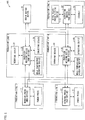
- Fig. 1 is an explanatory view illustrating (i) an overall configuration of a production plant (plant) 100 in accordance with the present embodiment and (ii) how a workpiece (object to be processed) is conveyed in the production plant 100.
- the production plant 100 includes a production line 1, a production line 2, a production line 3, a production line 4, a production line 5, and a resin drying device 61.
- Each of the production lines 1 through 5 is a small group (associated device group) made up of a plurality of production devices which are closely associated with each other in operation.
- the production line 1 includes a punch press 11 and a bending press 12.
- the punch press 11 produces a metal terminal (workpiece) having a given shape by pressing a metal hoop material.
- the bending press 12 precisely bends the metal terminal, produced by the punch press 11, while pressing the metal terminal so that the metal terminal has a given shape.
- the metal terminal thus bent by the bending press 12 is supplied to each of the production lines 3 and 4.
- the production line 2 includes a punch press 21 and a bending press 22, as well as the production line 1.
- the punch press 21 produces a metal terminal (workpiece) having a given shape by pressing a metal hoop material.
- the bending press 22 precisely bends the metal terminal, produced by the punch press 21, while pressing the metal terminal so that the metal terminal has a given shape.
- the metal terminal thus bent by the bending press 22 is supplied to each of the production lines 3 and 4.
- the production line 1 produces a metal terminal different, in type, from that produced by the production line 2.
- the production line 1 is similar, in configuration, to the production line 2.
- the production line 3 includes an injection molding device 31, a mold temperature adjusting device 32, a removing device (removing robot) 33, and a conveying device 34.
- the injection molding device 31 inserts, into a resin pellet supplied from the resin drying device 61, metal terminals produced by the respective production lines 1 and 2, and molds a product from the resin pellet and the metal terminals.
- the mold temperature adjusting device 32 adjusts a temperature of a mold provided in the injection molding device 31.
- the removing device 33 removes, from the injection molding device 31, the product molded by the injection molding device 31, and transfers such a molded product to the conveying device 34.
- the conveying device 34 supplies, to the production line 5, the product molded by the injection molding device 31. In this manner, a product in which two types of metal terminals, different in shape from each other, are inserted is molded by the injection molding device 31, and is supplied to the production line 5.
- the production line 4 includes an injection molding device 41, a mold temperature adjusting device 42, a removing device (removing robot) 43, and a conveying device 44, as well as the production line 3.
- the injection molding device 41 inserts, into a resin pellet supplied from the resin drying device 61, metal terminals produced by the respective production lines 1 and 2, and molds a product from the resin pellet and the metal terminals.
- the mold temperature adjusting device 42 adjusts a temperature of a mold provided in the injection molding device 41.
- the removing device 43 removes, from the injection molding device 41, the product molded by the injection molding device 41, and transfers such a molded product to the conveying device 44.
- the conveying device 44 supplies, to the production line 5, the product molded by the injection molding device 41. In this manner, a product in which two types of metal terminals, different in shape from each other, are inserted is molded by the injection molding device 41, and is supplied to the production line 5.
- the production line 3 is similar, in configuration, to the production line 4, and a molded product supplied from the production line 3 to the production line 5 is identical to that supplied from the production line 4 to the production line 5. That is, in the present embodiment, one type of molded product, which has an identical shape and in which two types of metal terminals that are different in shape from each other are inserted, is produced by each of the production lines 3 and 4.
- the resin drying device (shared device) 61 dries a resin pellet which is a material used in a process carried out by each of the injection molding devices 31 and 41, and supplies the resin pellet to the injection molding devices 31 and 41.
- the production line 5 includes a metal plate press fitting device 51, an inspection device (image processing device) 52, and a stocker 53.
- the metal plate press fitting device 51 presses a metal plate into a molded product supplied from each of the production lines 3 and 4.
- the inspection device 52 (i) captures an image of a molded product into which a metal plate is pressed by the metal plate press fitting device 51, (ii) inspects an appearance of the molded product in accordance with data of such a captured image, and (iii) transfers, to the stocker 53, the molded product which has passed such appearance inspection.
- the stocker 53 stocks therein a molded product supplied from the inspection device 52 (a finished product which has passed the appearance inspection).
- the production plant 100 is configured such that a process carried out by each of the production lines 1 and 2 has a production takt (processing speed) twice as fast as that of the injection molding device 31 (or the injection molding device 41), which carries out an injection molding process subsequent to the process carried out by each of the production lines 1 and 2. Therefore, in the present embodiment, two injection molding devices 31 and 41 provided in the production lines 3 and 4, respectively, are each configured to carry out the injection molding process.
- the production line 5 has a processing speed three times as fast as each processing speed of the production lines 3 and 4. Therefore, a mere single production line 5 is provided so as to carry out a process with respect to a molded product supplied from each of the production lines 3 and 4.
- each production takt of the production lines 1 and 2 is set to be identical to a total production takt of the production lines 3 and 4. This causes standby time or stock not to occur in the production lines 1 through 4 in normal operation.
- the production takt of the production line 5 is greater than each production takt of the production lines 3 and 4. This causes standby time, to wait for a workpiece to be supplied from each of the production lines 3 and 4, to occur in the production line 5 even in normal operation.
- the production line 5 is set to start the process every time workpieces supplied from the production lines 3 and 4 are stocked in given amount.
- the total production takt of the production lines 3 and 4 decreases to half of it in normal operation. This causes an increase in in-process stock in each of the production lines 1 and 2, unless each production takt of the production lines 1 and 2 is decreased to not more than half of it in normal operation.
- in-process stock increases in each of the production lines 3 and 4 unless the production lines 1 through 4 are stopped.
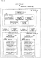
- Fig. 2 is an explanatory view illustrating how information is transmitted between production devices provided in the production plant 100.
- a plurality of production devices are provided in each of production lines, and one of the plurality of production devices provided in the each of the production lines is set, in advance, as a hub device (representative device).
- the one of the plurality of production devices which one is set as the hub device of the each of the production lines is, for example, a device (i) which has close association, in terms of operation, with the other one(s) of the plurality of production devices which one(s) constitutes the each of the production lines and (ii) which carries out a major process in the each of the production lines.
- the bending press 12 is set as a hub device of the production line 1
- the bending press 22 is set as a hub device of the production line 2
- the injection molding device 31 is set as a hub device of the production line 3
- the injection molding device 41 is set as a hub device of the production line 4
- the inspection device 52 is set as a hub device of the production line 5.
- Each hub device transmits operational information on itself to each of hub devices provided in respective associated lines (associated device groups), and receives operational information on the each of the hub devices from the each of the hub devices.
- Each of the associated lines is a production line (i) which is associated in advance with a control-target line (control-target device group) in which the each hub device is provided and (ii) which, for example, carries out, prior or subsequent to the control-target line, a process with respect to a workpiece to be processed.
- Fig. 3 is an explanatory view schematically illustrating a configuration of a control system for controlling the production plant 100.
- a plurality of production devices are provided in each of production lines.
- One of the plurality of production devices is set as a hub device H, and the other one(s) of the plurality of production devices is/are set as a subordinate device(s) A, B, ....
- the hub device H controls, depending on operational statuses of associated lines, operation of the hub device H and operation of the subordinate device(s) provided in the each (control-target line) of the production lines in which the hub device H is provided.
- a control system for controlling the production plant in accordance with the present embodiment is configured.
- the bending press 12 provided in the production line 1 is set as a hub device H
- the bending press 22 provided in the production line 2 is set as a hub device H
- the injection molding device 31 provided in the production line 3 is set as a hub device H
- the injection molding device 41 provided in the production line 4 is set as a hub device H
- the inspection device 52 provided in the production line 5 is set as a hub device H.
- the punch press 11 provided in the production line 1 serves as a subordinate device
- the punch press 21 provided in the production line 2 serves as a subordinate device
- the mold temperature adjusting device 32, the removing device 33, and the conveying device 34, provided in the production line 3 each serve as a subordinate device
- the mold temperature adjusting device 42, the removing device 43, and the conveying device 44, provided in the production line 4 each serve as a subordinate device
- the metal plate press fitting device 51 and the stocker 53, provided in the production line 5 each serve as a subordinate device.
- a hub device H includes a production processing section 101 and a control section (control device) 102.
- Each of subordinate devices A, B, ... includes a production processing section 201 and a control section 202.
- the production processing section 101 provided in the hub device H is a processing section which carries out a production process that the hub device H undertakes in a corresponding production line. That is, in a case where the bending press 12 provided in the production line 1 or the bending press 22 provided in the production line 2 serves as a hub device H, the production processing section 101 carries out a bending press process. In a case where the injection molding device 31 provided in the production line 3 or the injection molding device 41 provided in the production line 4 serves as a hub device H, the production processing section 101 carries out an injection molding process. In a case where the inspection device 52 provided in the production line 5 serves as a hub device H, the production processing section 101 carries out an inspection process.
- the control section 102 provided in the hub device H includes an electric power detecting section 111, an operational information generating section 112, an operational information obtaining section 113, an operation control section 114, and a storing section 115.
- the electric power detecting section 111 detects an amount of electric power consumed by the production processing section 101.
- the operational information generating section 112 determines an operational status of the production processing section 101 in accordance with an amount of electric power consumed by the production processing section 101 which amount is detected by the electric power detecting section 111. Depending on a result of such determination, the operational information generating section 112 generates operational information indicative of an operational status of the hub device H, and supplies the operational information to each of associated lines (hub devices provided in the respective associated lines) each of which is a production line associated in advance with the hub device H. Examples of the operational information encompass: information indicating whether the hub device H is in an operating state or a stopped state (non-operating state); and information indicating whether the hub device H is in a normal operating state, a low-speed operating state, or a stopped state (non-operating state).
- the operational information generating section 112 compares, with a threshold set in advance, an integrated value of an amount of electric power consumed by the production processing section 101 from given time ago to a present time. In a case where the integrated value is equal to or more than the threshold, the operational information generating section 112 determines that the hub device H is in an operating state. In a case where the integrated value is less than the threshold, the operational information generating section 112 determines that the hub device H is in a stopped state (non-operating state).
- the operational information generating section 112 compares, with first and second thresholds set in advance, an integrated value of an amount of electric power consumed by the production processing section 101 from given time ago to a present time. In a case where the integrated value is equal to or more than the first threshold, the operational information generating section 112 determines that the hub device H is in a normal operating state. In a case where the integrated value is less than the first threshold and equal to or more than the second threshold, the operational information generating section 112 determines that the hub device H is in a low-speed operating state. In a case where the integrated value is less than the second threshold, the operational information generating section 112 determines that the hub device H is in a stopped state (non-operating state).
- each hub device has an automatic operation setting mode and a manual operation setting mode.
- the automatic operation setting mode is a mode in which a hub device is registered in the control system for controlling the production plant 100 and operation of each of production devices, provided in a production line to which the hub device belongs, is controlled depending on operational statuses of associated lines.
- the manual operation setting mode is a mode in which the hub device is not registered in the control system for controlling the production plant 100 and the operation of the each of the production devices is individually controlled, irrespective of operation of the associated lines.
- the automatic operation setting mode is used in a case where the production plant 100 carries out a process for the purpose of high-volume production under a production schedule.
- the manual operation setting mode is used in a case where, for example, a production line is manufactured by way of trial or in a case where operation of a production line is tested.
- the operational information obtaining section 113 obtains, from each of the associated lines (the hub devices provided in the respective associated lines) each of which is a production line associated in advance with the hub device H (or the production line to which the hub device H belongs), operational information indicative of an operational status of the each of the associated lines (or the hub devices provided in the respective associated lines).
- the operation control section 114 controls operation of the production processing section 101 provided in the hub device H, (ii) generates control information in accordance with which operation of the subordinate devices, provided in the production line (control-target line) to which the hub device H belongs, is controlled, and (iii) supplies the control information to the subordinate devices.
- the storing section 115 stores therein control setting information (first setting information) in which a combination of operational statuses of the associated lines is associated with corresponding contents of control (for example, turning on/off the control-target line or changing a processing speed) carried out with respect to the control-target line.
- control setting information first setting information
- first setting information a combination of operational statuses of the associated lines is associated with corresponding contents of control (for example, turning on/off the control-target line or changing a processing speed) carried out with respect to the control-target line.
- the storing section 115 further stores therein control-target information (second setting information) which specifies, for each operational status of the hub device H, contents of control carried out with respect to production devices (subordinate devices) other than the hub device H, among a plurality of production devices provided in the control-target line.
- control-target information (second setting information) which specifies, for each operational status of the hub device H, contents of control carried out with respect to production devices (subordinate devices) other than the hub device H, among a plurality of production devices provided in the control-target line.
- the storing section 115 further stores therein control setting information (third setting information) in which operational statuses (or electric power consumption) of the production devices (subordinate devices) other than the hub device H, among the plurality of production devices provided in the control-target line, is associated with contents of control carried out with respect to the production processing section 101 provided in the hub device H.
- control setting information third setting information in which operational statuses (or electric power consumption) of the production devices (subordinate devices) other than the hub device H, among the plurality of production devices provided in the control-target line, is associated with contents of control carried out with respect to the production processing section 101 provided in the hub device H.
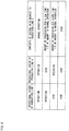
- Fig. 4 is an explanatory view illustrating an example of control setting information (first setting information) stored in a storing section 115 of the bending press (hub device) 12 provided in the production lines 1 and 2.
- each of the production lines 1 and 2 (the bending presses 12 and 22, which are hub devices provided in the production lines 1 and 2, respectively) is set to operate in a normal operating state in a case where each of the production lines (associated lines) 3 and 4 is in an operating state (in a case where each of the injection molding devices 31 and 41, which are hub devices provide in the production lines 3 and 4, respectively, is in an operating state).
- each of the production lines 1 and 2 (the bending presses 12 and 22, which are hub devices provided in the production lines 1 and 2, respectively) is set to operate in a low-speed operating state in which a processing speed (an amount of metal terminals produced per given time) is decreased to half of it in the normal operating state, in a case where (i) any one of the production lines 3 and 4 is in an operating state and (ii) the other is in a stopped state.
- examples of a method of causing each of the production lines 1 and 2 to operate in the low-speed operating state encompass: a method in which an operation speed itself of each production device (the bending presses 12 and 22) is decreased; and a method in which standby time is set until when each production device (the bending presses 12 and 22) starts processing a next metal terminal, every time the each production device finishes processing a given amount of metal terminals (workpieces).
- the standby time the each production device can be turned off during the standby time. Alternatively, supply of electric power to a production processing section provided in the each production device can be stopped.
- each of the production lines 1 and 2 (the injection molding devices 31 and 41, which are hub devices provided in the production lines 3 and 4, respectively) is set to be in a stopped state in a case where each of the production lines 3 and 4 is in a stopped state.
- each production device (the bending presses 12 and 22) can be turned off while each of the production lines 1 and 2 is in the stopped state.
- supply of electric power to the production processing section provided in the each production device can be stopped.
- Fig. 5 is an explanatory view illustrating an example of control setting information (first setting information) stored in each storing section 115 of the injection molding devices (hub devices) 31 and 41 provided in the production lines 3 and 4, respectively.
- each of the production lines 3 and 4 (the injection molding devices 31 and 41, which are hub devices provided in the production lines 3 and 4, respectively) is set to operate in a normal operating state in a case where the production lines (associated lines) 1, 2, and 5 and the resin drying device 61 are each in an operating state.
- each of the production lines 3 and 4 (the injection molding devices 31 and 41, which are hub devices provided in the production lines 3 and 4, respectively) is set to be in an stopped state in a case where any one of the production lines (associated lines) 1, 2, and 5 and the resin drying device 61 is in an stopped state.
- each production device (the injection molding devices 31 and 41) can be tuned off. Alternatively, supply of electric power to a production processing section provided in the each production device can be stopped.
- Fig. 6 is an explanatory view illustrating an example of control setting information (first setting information) stored in a storing section 115 of the inspection device (hub device) 52 provided in the production line 5.
- the production line 5 (the inspection device 52, which is a hub device provided in the production line 5) is set to operate in a normal operating state in a case where each of the production lines (associated lines) 3 and 4 is in an operating state (in a case where each of the injection molding devices 31 and 41 provided in the production lines 3 and 4, respectively, is in an operating state).
- the production line 5 (the inspection device 52, which is a hub device provided in the production line 5) is set to operate in a low-speed operating state in which a processing speed (an amount of molded products inspected per given time) is decreased to half of it in the normal operating state, in a case where (i) any one of the production lines (associated lines) 3 and 4 is in the operating state and (ii) the other is in the stopped state.
- examples of a method of causing the production line 5 to operate in the low-speed operating state encompass a method in which (i) the production line 5 is arranged to sequentially or collectively process a given amount of molded products supplied to the production line 5 and (ii) standby time, until when the production line 5 starts processing a next given amount of molded products after processing the given amount of molded products, is set to be longer than a period of the normal operating state.
- each production device provided in the production line 5 can be tuned off during the standby time. Alternatively, supply of electric power to a production processing section provided in the each production device can be stopped.
- the operation control section 114 generates, in accordance with (i) an operational status of the hub device H and (ii) the second setting information stored in the storing section 115, control information used to control operation of the other production devices (subordinate devices) provided in the production line to which the hub device H belongs, and then supplies the control information to the other production devices.
- the operational information generating section 112 generates operational information indicative of the operational status of the hub device H, and supplies the operational information to each of the associated lines (the hub devices provided in the respective associated lines).
- the operation control section 114 controls operation of the production processing section 101 provided in the hub device H, in accordance with (i) operational statuses of the subordinate devices and (ii) the third setting information stored in the storing section 115. Further, the operation control section 114 generates, in accordance with (i) the operational status of the hub device H and (ii) the second setting information stored in the storing section 115, control information used to control operation of the other production devices (subordinate devices), and supplies the control information to the other production devices.
- the operational information generating section 112 generates operational information indicative of the operational status of the hub device H, and supplies the operational information to each of the associated lines (the hub devices provided in the respective associated lines).
- the operation control section 114 detects an operational status of each of the subordinate devices in accordance with an amount of electric power consumed by the each of the subordinate devices. For example, the operation control section 114 compares, with a threshold set in advance, an integrated value of an amount of electric power consumed by a subordinate device from given time ago to a present time. In a case where the integrated value is decreased to less than the threshold, the operation control section 114 detects that the subordinate device is stopped. In a case where any one of the subordinate devices is stopped, the operation control section 114 stops the production line to which the hub device H belongs.
- the operation control section 114 stops production operation of the production processing section 101 provided in the hub device H, and supplies, to the subordinate devices, a control signal for stopping production operation of the subordinate devices.
- an operation signal indicating that the hub device H is in a stopped state is generated by the operational information generating section 112, and supplied to each of the associated lines.
- the operation control section 114 can detect a processing speed of each of the subordinate devices in accordance with an amount of electric power consumed by the each of the subordinate devices, and control each of the plurality of production devices (the hub device H and the subordinate devices), provided in the production line to which the hub device H belongs, so as to operate at a processing speed corresponding to the processing speed thus detected.
- each of the subordinate devices A, B, ... includes the production processing section 201 and the control section 202.
- the control section 202 includes an electric power detecting section 211, an electric power information output section 212, a control information obtaining section 213, and an operation control section 214.
- the production processing section 201 provided in each subordinate device carries out a production process assigned to the each subordinate device. For example, in a case where the punch press 11 provided in the production line 1 or the punch press 21 provided in the production line 2 serves as a subordinate device, the production processing section 201 carries out a punch press process. In a case where the mold temperature adjusting device 32 provided in the production line 3 or the mold temperature adjusting device 42 provided in the production line 4 serves as a subordinate device, the production processing section 201 adjusts a temperature of a mold.
- the production processing section 201 removes a molded production (workpiece) from an injection molding device.
- the production processing section 201 conveys a molded product (workpiece) removed by a removing section from an injection molding device.
- the production processing section 201 presses a metal into a molded product.
- the production processing section 201 stocks therein a product which has passed an inspection carried out by the inspection device 52.
- the electric power detecting section 211 detects an amount of electric power consumed by the production processing section 201.
- the electric power information output section 212 generates electric power information which varies depending on the amount of the electric power detected by the electric power detecting section 211, and supplies the electric power information to the hub device H of the production line to which the subordinate device belongs.
- the electric power information can be alternatively indicative of a detection value of the amount of the electric power consumed by the production processing section 201 or can be alternatively an integrated value obtained by integrating the detection value of the amount of the electric power with given time.
- the control information obtaining section 213 obtains control information supplied from the hub device H.
- control information encompass control information used to stop production operation of the subordinate device, control information used to turn off the subordinate device, and control information used to change a processing speed of the subordinate device.
- the operation control section 214 controls operation of the production processing section 201 in accordance with control information obtained by the control information obtaining section 213 from the hub device H.
- the resin drying device 61 has a configuration similar to that of the hub device H. That is, the resin drying device 61 incudes: a production processing section 101 which dries a resin pellet and supplies the resin pellet thus dried to each of the injection molding devices 31 and 41; and a control section 102 including an electric power detecting section 111, an operational information generating section 112, an operational information obtaining section 113, an operation control section 114, and a storing section 115.
- the electric power detecting section 111 detects an amount of electric power consumed by the production processing section 101.
- the operational information generating section 112 determines an operational status of the production processing section 101 in accordance with an amount of electric power consumed by the production processing section 101 which amount is detected by the electric power detecting section 111. Depending on a result of such determination, the operational information generating section 112 generates operational information indicative of an operational status of the resin drying device 61, and supplies the operational information to each of production devices (the injection molding devices 31 and 41) associated in advance with the resin drying device 61.
- the operational information obtaining section (obtaining section) 113 obtains, from each of the production devices (the injection molding devices 31 and 41) associated in advance with the resin drying device 61, operational information indicative of an operational status of the each of the production devices.
- the operation control section (control section) 114 controls operation of the production processing section 101 provided in the resin drying device 61 in accordance with (i) operational information on the each of the production devices which information is obtained by the operational information obtaining section 113 and (ii) control setting information (control information) stored in the storing section 115.
- the storing section (setting storing section) 115 stores therein control setting information (setting information) in which a combination of operational statuses of the production devices (injection molding devices 31 and 41) associated in advance with the resin drying device 61 is associated with corresponding contents of control carried out with respect to the resin drying device 61.
- the control setting information is set such that, in a case where each of the injection molding devices (hub devices) 31 and 41 is stopped, operation of the resin drying device 61 is stopped and the resin drying device 61 is turned off.
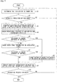
- a control section 102 provided in a hub device determines that the hub device is turned on (step S1). This determination can be made, for example, depending on whether or not an amount of electric power consumed by a production processing section 101, which amount is detected by an electric power detecting section 111, is increased to a given value or more.
- control section 102 determines whether the hub device is set in an automatic operation setting mode or a manual operation setting mode (step S2). Note that the automatic operation setting mode and the manual operation setting mode can be switched, for example, in a case where a manager of production lines operates a mode switching button provided on the hub device.
- control section 102 determines, in the step S2, that the hub device is not set in the automatic operation setting mode, the control section 102 returns to the step S1.
- control section 102 determines, in the step S2, that the hub device is set in the automatic operation setting mode
- the control section 102 registers the hub device in a control system for controlling a production plant 100 (step S3). That is, the control section 102 supplies, to hub devices provided in associated lines, operational information on the hub device so as to register the hub device in the control system, and carries out a process in the automatic operation setting mode in which a production line is controlled in consideration of operational statuses of associated lines.
- control section 102 checks operational statuses of the hub device and a subordinate device(s) provided in a production line to which the hub device belongs (step S4). Specifically, the control section 102 checks an operational status of the hub device in accordance with the amount of the electric power consumed by the production processing section 101 provided in the hub device which amount is detected by the electric power detecting section 111, and checks an operational status(es) of the subordinate device(s) in accordance with electric power information, on the subordinate device(s), supplied from the subordinate device(s).
- control section 102 determines whether or not it is necessary to change contents of control carried out with respect to the production line to which the hub device belongs, in accordance with the operational statuses of the hub device and the subordinate device(s) which operational statuses have been checked in the step S4 (step S5).
- control section 102 determines whether or not it is necessary to change contents of control carried out with respect to the subordinate device(s), in accordance with (i) the operational status of the hub device and (ii) second setting information stored in a storing section 115, and determines whether or not it is necessary to change contents of control carried out with respect to each of the hub device and the subordinate device(s), in accordance with the operational status(es) of the subordinate device(s) and the second setting information stored in the storing section 115.
- control section 102 determines, in the step S5, that it is not necessary to change the contents of control carried out with respect to the production line to which the hub device belongs, the control section 102 obtains operational information from each of the associated lines via the operational information obtaining section 113, and checks the operational statuses of the associated lines (operational statuses of the hub devices provided in the associated lines) (step S6).
- the control section 102 determines whether or not it is necessary to change the contents of control carried out with respect to the production line to which the hub device belongs, in accordance with (i) a combination of the operational statuses of the associated lines and (ii) first setting information stored in the storing section 115 (step S7).
- control section 102 determines, in the step S5 or S7, that it is necessary to change the contents of control carried out with respect to the production line to which the hub device belongs, the control section 102 changes the contents of control carried out with respect to the production line to which the hub device belongs, depending on the operational statuses of the hub device and the subordinate device(s) which operational statuses have been checked in the step S4 or depending on the operational statuses of the associated lines which operational statuses have been checked in the step S7 (step S8).
- control section 102 checks, in the step S4, that the production processing section 101 provided in the hub device or the production processing section 201 provided in the subordinate device(s), is stopped, the control section 102 stops the hub device and the subordinate device(s).
- the control section 102 can be arranged to turn off the hub device and the subordinate device(s) (or stop supply of electric power to the production processing section 101 provided in the hub device and to the production processing section 201 provided in the subordinate device(s)).
- control section 102 determines the contents of control carried out with respect to each of production devices provided in the production line to which the hub device belongs, depending on the first setting information stored in the storing section 115.
- control section 102 determines, in the step S7, that it is not necessary to change the contents of control carried out with respect to the production line to which the hub device belongs and (ii) in a case where the control section 102 has changed, in the step S8, the contents of control carried out with respect to the production line to which the hub device belongs, the control section 102 generates operational information on the hub device, and supplies the operational information to each of the associated lines (each of the hub devices provided in the respective associated lines) (step S9).
- the electric power detecting section 111 detects an amount of electric power consumed by the production processing section 101.
- the operational information generating section 112 then detects an operational status of the production processing device 101 in accordance with the amount of the electric power which amount is detected by the electric power detecting section 111, generates operational information based on a result of such a detection, and supplies the operational information to each of the associated lines (each of the hub devices provided in the associated lines).
- control section 102 determines whether or not to end a production process. In a case where the control section 102 determines to continue the production process, the control section 102 returns to the step S1.
- a production line to which the production device belongs is again registered in the control system, for controlling the production plant 100, by manually or automatically restarting the production device and carrying out the steps S1 through 3.
- each of a plurality of production lines is made up of production devices which have direct association therebetween, and one of the production devices which one undertakes a major role in the each of the plurality of production lines is set as a hub device.
- control setting information first setting information
- a combination of operational statuses of the associated lines hub devices provided in the respective associated lines
- the hub device is associated with contents of control carried out with respect to the hub device provided in the each of the plurality of production lines.
- control setting information indicative of contents of control carried out with respect to a subordinate device(s) which contents vary depending on an operational status of the hub device
- control setting information third setting information indicative of contents of control carried out with respect to the hub device which contents vary depending on an operational status(es) of the subordinate device(s).
- operation of a hub device provided in a production line to which the any one of the production devices belongs is controlled depending on the change in operational status of the any one of production device.
- operation of a subordinate device(s) provided in the production line, to which the hub device belongs is controlled depending on such a change in operational status of the hub device, and operational information indicative of the operational status of the hub device is supplied to each of hub devices provided in respective associated lines.
- operation of a hub device and a subordinate device(s) provided in the production line is controlled depending on a combination of operational statuses of the associated lines associated with the production line.
- the present embodiment is arranged such that, while association between hub devices provided in the respective plurality of production lines are sequentially expanded, energy-saving control is carried out with respect to each of the production devices constituting each of the plurality of production lines. This causes a limitation not to be imposed on a range of production devices to be controlled. It is therefore possible to easily establish an energy-saving control system, even in a case where a production plant includes a large number of production lines.
- each of the plurality of production lines is a control element (small group) made up a hub device and other production devices.
- This makes it possible to easily design energy-saving control system merely by changing a definition of association between the plurality of production lines and/or between the production devices provided in each of the plurality of production lines, even in a case where rearrangement of the plurality of production lines is necessitated due to addition or removal of a production line or due to a change in production planning. That is, it is possible to easily and flexibly change a production device to be controlled or contents of control, depending on an actual operating state such as progress of production and a change in production planning.
- each of the production devices includes a control section (control section 102 or 202) which controls operation of the each of the production devices depending on operational statuses or a combination of operational statuses of the other ones of the production devices.
- control section 102 or 202 which controls operation of the each of the production devices depending on operational statuses or a combination of operational statuses of the other ones of the production devices.
- the present embodiment can be alternatively arranged such that (i) a control device (not illustrated) is provided which controls operation of all or ones of the production devices, provided in the production plant 100, as control-target production devices and (ii) the control device controls operation of the control-target production devices depending on operational statuses or a combination of operational status of devices associated with the control-target production devices. That is, functions of control sections provided in all or ones of the production devices can be carried out by a single control device.
- the control device can be provided in any one of the production devices. Alternatively, the control device can be provided separately from the production devices.
- operational information generated in accordance with an amount of electric power consumed by all (or ones) of the production devices provided in the production plant 100 or in accordance with information indicative of the amount of the electric power, is supplied to the control device.
- This allows an amount of electric power consumed by the whole production plant 100 to be easily understood, and allows an effect of a reduction in electric power consumption (or an energy-saving effect) to be easily verified.
- each hub device (i) transmits, to each of hub devices provided in respective associated lines, operational information on the each hub device which information is generated in accordance with an amount of electric power consumed by the each hub device and (ii) receives, from the each of the hub devices, operational information on the each of the hub devices which information is generated in accordance with an amount of electric power consumed by the each of the hub devices.
- the present embodiment is not limited to such.
- the present embodiment can be alternatively arranged such that each hub device transmits information indicative of an amount of electric power consumed by the each hub device (a detection value of electric power consumption or an integrated value of electric power consumption).
- each hub device transmits information indicative of an amount of electric power consumed by the each hub device
- a hub device which receives the information can detect an operational status of the each hub device, provided in an associated line, by making calculation with the use of the information (for example, by comparing, with a threshold, electric power consumption or an integrated value of electric power consumption).
- each of the production lines 1 and 2 individually obtains operational information supplied from the production line 3 and operational information supplied from the production line 4.
- the present embodiment is not limited to such.
- the present embodiment can be alternatively arranged such that, for example, each of the production lines 1 and 2 (i) receives information indicative of a total amount of electric power consumed by the hub devices provided in the respective production lines 3 and 4 and (ii) determines, depending on the total amount, operational statuses of the production lines 3 and 4 (whether both of the production lines 3 and 4 are in operation, whether only one of the production lines 3 and 4 is in operation, or whether both of the production lines 3 and 4 are stopped).
- the resin drying device (shared device) 61 is provided which supplies a resin pellet to each of the injection molding device (associated device) 31 provided in the production line 3 and the injection molding device (associated device) 41 provided in the production line 4.
- This resin drying device 61 is arranged to exchange operational information with the injection molding devices 31 and 41 and to stop its operation in a case where the injection molding devices 31 and 41 are stopped.
- such a shared device that is shared by a plurality of associated devices cannot control its operation depending on only an amount of electric power consumed by one of the plurality of associated devices (or depending on only an operational status of one of the plurality of associated devices).
- the shared device is capable of controlling its operation by controlling its operation depending on the combination of the operational statuses of the plurality of associated devices.
- the shared device is not limited the resin drying device 61.
- a compressed air supplying device, an exhaust device, an air conditioner, a lighting device, a cooling water pump, a nitrogen gas supplying device, or the like can be, for example, set as a shared device.
- Each of these shared devices can control its operational status depending on operational statuses of associated devices which are associated with the each of the shared devices, by setting, to the each of the shared devices, a control method which varies depending on a combination of the operational statuses (or electric power consumption) of the associated devices.
- the exhaust device can stop its operation (or turned off itself) when all of associated devices which are associated with the exhaust device are stopped.
- the exhaust device can stop part of its operation which part corresponds to the part of the associated devices. Note that, in a case where the exhaust device stops merely part of its operation which part corresponds to the part of the associated devices, this may cause an adversely effect on an entire exhaust system. That is, an exhaust state may become unstable or exhaust efficiency may be decreased, thereby rather causing an increase in electric power consumption.
- the exhaust device preferably stops its operation when all of the associated devices, which are associated with the exhaust device, are stopped.
- the compressed air supplying device can be configured as follows. That is, when part of associated devices which are associated with the compressed air supplying device is stopped, the compressed air supplying device stops supplying compressed air to the part of the associated devices (or associated devices which are associated in advance with the part of the associated device), while continuing to supply compressed air to the other of the associated devices. This causes unnecessary supply of compressed air to be stopped. It is therefore possible to reduce a load on a compressor and possible to achieve energy saving.
- the supply of compressed air to the part of the associated devices can be stopped by, for example, (i) providing supply blocking means, such as a solenoid valve, in a passage through which compressed air is supplied to the part of the associated devices and (ii) control device (not illustrated), provided in the compressed air supplying device, controlling the supply blocking means depending on a combination of operational statuses of the associated devices.
- supply blocking means such as a solenoid valve
- the plurality of associated devices can belong to respective different production lines. That is, the present embodiment is arranged such that a small group of production devices, which have direct association therebetween, serves as a production line and operation of the production line is controlled depending on a combination of operational statuses of production lines associated with the production line. Alternatively, the present embodiment can be arranged such that, separately from a definition of a production line, a second small group is defined which is constituted by a shared device and associated devices associated with the shared device and operation of the shared device is controlled depending on a combination of operational statuses of the associated devices.
- the present embodiment has described a case where the present invention is applied to a production plant constituted by a plurality of production lines each including a plurality of production devices.
- the present embodiment is not limited to such a case. That is, the present invention is applicable to various types of plants (facilities, equipment) which include a plurality of device groups each made up of a plurality of devices.
- control section (control device) of each hub device of the present embodiment can be a control device for controlling operation of a control-target device group which is one of a plurality of device groups each made up of a plurality of devices, including: an operational information obtaining section which obtains, from each of associated device groups, operational information indicative of an operational status of the each of the associated device groups, the associated device groups being ones of the plurality of device groups which ones are associated in advance with the control-target device group; a storing section in which stored are (i) first control setting information specifying, depending on the operational status of the each of the associated device groups, contents of control carried out with respect to a representative device which is a predetermined one of the plurality of devices provided in the control-target device group and (ii) second setting information specifying, depending on an operational status of the representative device, contents of control carried out with respect to ones of the plurality of devices provided in the control-target device group which ones are other than the representative device; an operation control section which (a) controls operation of the representative device in accordance with
- the present embodiment has described a configuration in which a hub device provided in a control-target line controls operation of the hub device and a subordinate device(s) depending on a combination of operational statuses of a plurality of associated lines.
- the present embodiment is not always limited to such a configuration.
- the present embodiment can be alternatively arranged such that the hub device controls operation of the hub device and the subordinate device(s) depending on an operational status of a single associated line.
- operational information on an associated device group can be information indicative of an operational status of a representative device provided in the associated device group, the representative device being a predetermined one of devices provided in the associated device group.
- control section is arranged such that: in the storing section, third setting information is stored which specifies, , depending on operational statuses of the ones of the plurality of devices provided in the control-target device group which ones are other than the representative device, contents of control carried out with respect to the representative device; the operation control section controls operation of the representative device in accordance with (i) information which indicates an operational status of each of the plurality of devices provided in the control-target device group and which is received from the each of the plurality of devices and (ii) the third setting information; the operation control section controls operation of the ones, other than the representative device, of the plurality of devices provided in the control-target device group, in accordance with an operational status of the representative device and the second setting information; and the operational control section further includes: an operational information generating section which generates operational information indicative of the operational status of the representative device; and an operational information supplying section which supplies, to each of the associated device groups, the operational information which the operational information generating section has generated.
- each of associated device groups it is possible to control operation of a representative device and the other devices, than the representative device, provided in a control-target device group, depending on a change in operational status of any one of devices provided in the control-target device group. Furthermore, it is possible to cause each of associated device groups to carry out control reflecting an operational status of the control-target device group, by supplying, to the each of the associated device groups, operational information indicative of an operational status of the representative device provided in the control-target device group.
- each block of the aforementioned hub device and/or subordinate device can be implemented by hardware such as a logic circuit provided on an integrated circuit (IC chip) or can alternatively be implemented by software with the use of a CPU (Central Processing Unit).
- IC chip integrated circuit
- CPU Central Processing Unit
- the hub device and/or the subordinate device includes: a CPU which executes instructions of a program that carries out the foregoing functions; and a storage device (recording medium) such as a ROM (Read Only Memory) which stores the program, a RAM (Random Access Memory) in which the program is loaded, and a memory which stores the program and various sets of data.
- a storage device such as a ROM (Read Only Memory) which stores the program, a RAM (Random Access Memory) in which the program is loaded, and a memory which stores the program and various sets of data.
- the object of the present invention can be attained by (i) supplying, to the hub device and/or subordinate device, the recoding medium in which program codes (an executable program, an intermediate code program, and a source program) of a program for controlling the hub device and/or subordinate device, each of which is implemented by software that executes the foregoing functions, are computer-readably recorded and (ii) causing a computer (or a CPU or an MPU) of the hub device and/or subordinate device to read and execute the program codes recorded in the recording medium.
- program codes an executable program, an intermediate code program, and a source program
- the recording medium includes a non-transitory tangible medium, i.e., (i) tapes such as a magnetic tape and a cassette tape; (ii) disks including magnetic disks, such as a floppy (Registered Trademark) disk and a hard disk, and optical disks, such as a CD-ROM, an MO, an MD, a DVD, and a CD-R; (iii) cards such as an IC card (including a memory card) and an optical card; (iv) semiconductor memories such as a mask ROM, EPROM, EEPROM (Registered Trademark), and a flash ROM; and (v) logic circuits such as a PLD (Programmable Logic Device) and an FPGA (Field Programmable Gate Array).
- tapes such as a magnetic tape and a cassette tape
- optical disks such as a CD-ROM, an MO, an MD,
- the hub device and/or subordinate device can be connected to a communication network so that the program codes are supplied to the hub device and/or subordinate device via the communication network.
- This communication network is not limited to any particular one, provided that the program codes can be transmitted.
- Examples of the communication network include the Internet, an intranet, an extranet, a LAN, ISDN, VAN, a CATV communications network, a virtual private network, a telephone network, a mobile telecommunications network, and a satellite communication network.
- a transmission medium by which the communication network is constituted is not limited to any particular one, provided that the program codes can be transmitted.
- the transmission medium examples include: wired transmission media such as IEEE1394, a USB, a power-line carrier, a cable TV circuit, a telephone line, and ADSL (Asymmetric Digital Subscriber Line); and wireless transmission media such as infrared communication systems such as IrDA and a remote control, Bluetooth (Registered Trademark), IEEE802.11 wireless communication system, HDR (High Digital Rate), NFC (Near Field Communication), DLNA (Digital Living Network Alliance), a mobile phone network, a satellite circuit, and a digital terrestrial network.
- wired transmission media such as IEEE1394, a USB, a power-line carrier, a cable TV circuit, a telephone line, and ADSL (Asymmetric Digital Subscriber Line
- wireless transmission media such as infrared communication systems such as IrDA and a remote control, Bluetooth (Registered Trademark), IEEE802.11 wireless communication system, HDR (High Digital Rate), NFC (Near Field Communication), DLNA (Digital Living Network Alliance), a mobile phone network, a satellite circuit, and a digital terrestrial network.
- a control device in accordance with an embodiment of the present invention is a control device for controlling operation of a control-target device group which is one of a plurality of device groups each made up of a plurality of devices, including: an operational information obtaining section which obtains, from each of associated device groups, operational information indicative of an operational statuses of the each of the associated device groups, the associated device groups being device groups associated in advance with a control-target device group among a plurality of device groups; a storing section in which first control setting information is stored, the first control setting information specifying, for each combination of operational statuses of the associated device groups, contents of control carried out with respect to the control-target device group; and an operation control section which controls operation of the control-target device group in accordance with (i) the operational information on the each of the associated device groups, which operational information has been obtained by the operational information obtaining section, and (ii) the first control setting information stored in the storing section.
- control device can be arranged such that the operational information is information indicating whether the each of the associated device groups, which corresponds to the operational information, is in an operating state or a stopped state.
- the information indicating whether the each of the associated device groups is in an operating state or a stopped state can be information indicating whether the each of the associated device groups is turned on or off.
- control device can be arranged such that the operational information is any one of (1) information indicating whether a representative device, which is a predetermined one of devices provided in the each of the associated device groups that corresponds to the operational information, is in an operating sate or a stopped state, (2) information indicative of an amount of electric power consumed by the representative device, (3) information indicative of a total amount of electric power consumed by the each of the associated device groups that corresponds to the operational information, and (4) information indicative of a total amount of electric power consumed by the representative device provided in the each of the associated device groups that corresponds to the operational information.
- an operational status of each of associated device groups is determined depending on (1) information indicating whether a representative device, which is a predetermined one of a plurality of devices provided in the each of the associated device groups that corresponds to the operational information, is in an operating sate or a stopped state, (2) information indicative of an amount of electric power consumed by the representative device, (3) information indicative of a total amount of electric power consumed by the each of the associated device groups, or (4) information indicative of a total amount of electric power consumed by the representative device, and operation of the control-target device group is controlled depending on a combination of operational statuses of the associated device groups.
- control device can be arranged such that: the control-target device group supplies, to the each of the associated device groups, an object which the control-target device group has processed; the first control setting information is set such that, as the number of operating ones of the associated device groups, each of which processes the object supplied from the control-target device group, becomes smaller, the number of objects processed per given time by the control-target device group becomes smaller.
- control-target device group it is possible to control the number of objects processed per given time by a control-target device group, depending on the number of associated device groups to which the objects are supplied. This allows a reduction in load on the control-target device group and, accordingly, allows energy saving to be realized. Furthermore, it is possible to prevent the control-target device group from having an excess throughput and therefore having stocks, in a case where part of the associated device groups is in a non-operating state. Moreover, it is possible to prevent each of the associated device groups from having standby time, in a case where the number of the associated device groups in an operating state is increased and, consequently, the control-target device group has an insufficient throughput.
- control device can be arranged such that: the control-target device group produces a product with the use of different objects supplied from the respective associated device groups; and the first control setting information is set such that, in a case where any one of the associated device groups is in a stopped state, operation of the control-target device group is switched to a stopped state.
- a control-target device group which produces a product with the use of different objects supplied from the respective associated device groups, cannot produce a product.
- any one of the associated device groups in a stopped state, it is possible to switch operation of the control-target device group to a stopped state. This allows energy, consumed due to unnecessary operation of the control-target device group, to be suppressed and, accordingly, allows energy saving to be realized.
- the control-target device group in a case where the control-target device group cannot produce a product, it is possible to stop the control-target device group. It is therefore possible to prevent objects, supplied from part of the associated device groups, from being stored in the control-target device group and, accordingly, possible to prevent the control-target device group from having excess stocks.
- control device can be arranged such that: the control-target device group carries out a common process with respect to an identical object supplied from each of the associated device groups; the first control setting information is set such that, as the number of operating ones of the associated device groups, each of which supplies the identical object to the control-target device group, becomes smaller, the number of objects processed per given time by the control-target device group becomes smaller.
- control device can be arranged such that: the first control setting information specifying, for the each combination of the operational statuses of the associated device groups, contents of control carried out with respect to a representative device which is a predetermined one of devices provided in the control-target device group; in the storing section, second setting information is stored which specifies, depending on an operational status of the representative device provided in the control-target device group, contents of control carried out with respect to the other one, than the representative device, of the devices provided in the control-target device group; the operation control section controls operation of the representative device provided in the control-target device group, in accordance with (i) the operational information on the each of the associated device groups which operational information has been obtained by the operational information obtaining section and (ii) the first control setting information; and the operation control section controls operation of the other one, than the representative device, of the devices provided in the control-target device group, in accordance with the operational status of the representative device and the second setting information.
- control device can be arranged such that: in the storing section, second setting information and third setting information are stored, the second setting information specifying, depending on an operational status of a representative device which is a predetermined one of devices provided in the control-target device group, contents of control carried out with respect to the other one, than the representative device, of the devices provided in the control-target device group, the third setting information specifying, depending on an operational status of each of the devices provided in the control-target device group, contents of control carried out with respect to the representative device; the operation control section controls operation of the representative device provided in the control-target device group, in accordance with (i) information which is received from the each of the devices provided in the control-target device group and which indicates an operational status of the each of the devices and (ii) the third setting information; the operation control section controls operation of the other one, than the representative device, of the devices provided in the control-target device group, in accordance with the operational status of the representative device and the second setting information; and the operation control section further includes: an operational information generating section
- each of associated device groups it is possible to control operation of a representative device and the other devices, than the representative device, provided in a control-target device group, depending on a change in operational status of any one of devices provided in the control-target device group. Furthermore, it is possible to cause each of associated device groups to carry out control reflecting an operational status of the control-target device group, by supplying, to the each of the associated device groups, operational information indicative of an operational status of the representative device provided in the control-target device group.
- a control system in accordance with an embodiment of the present invention is a system for controlling a plant including a plurality of device groups each of which is made up of a plurality of devices, the system including: any one of the foregoing control devices.
- control-target device group it is possible to control operation of a control-target device group depending on a combination of operational statuses of associated device groups, even in a case where the control-target device group is affected by the operational statuses of the associated device groups. This makes it possible to effectively reduce energy consumed by a plant constituted by a plurality of device groups.
- control system can be arranged to further includes: a shared device which carries out a process associated with devices scattered in a plurality of device groups, the shared device including: an obtaining section which obtains, from each of the devices associated with the process carried out by the shared device, operational information indicative of an operational status of the each of the devices: a setting storing section in which setting information is stored, the setting information specifying, for each combination of operational statuses of the devices, contents of control carried out with respect to operation of the shared device; and a control section which controls operation of the shared device in accordance with (i) the operational information on the each of the devices, which operational information has been obtained by the obtaining section, and (ii) the setting information stored in the setting storing section.
- a shared device which carries out a process associated with devices scattered in a plurality of device groups, the shared device including: an obtaining section which obtains, from each of the devices associated with the process carried out by the shared device, operational information indicative of an operational status of the each of the devices: a setting storing section
- a control method in accordance with the present invention is a method for causing a control device to control operation of a control-target device group which is one of a plurality of device groups each made up of a plurality of devices, including the steps of: (a) causing the control device to obtain, from each of associated device groups, operational information indicative of an operational status of the each of the associated device groups, the associated device groups being device groups associated in advance with a control-target device group; and (b) causing the control device to control operation of the control-target device group in accordance with (i) the operational information on the each of the associated device groups, which operational information has been obtained in the step (a), and (ii) first control setting information stored in advance in a storing section, the first control setting information specifying, for each combination of operational statuses of the associated device groups, contents of control carried out with respect to the control-target device group.
- control-target device group it is possible to control operation of a control-target device group depending on a combination of operational statuses of associated device groups, even in a case where the control-target device group is affected by the operational statuses of the associated device groups. This makes it possible to effectively reduce energy consumed by a plant constituted by a plurality of device groups.
- control method can be realized by a computer.
- scope of the present invention also encompasses (i) a program for causing the computer to carry out each step of the method and (ii) a computer-readable recording medium in which the program is recorded.
- the present invention is applicable to a control device and a control method each for controlling a plurality of device groups which constitute a plant and each of which is made up of a plurality of devices.
- the present invention is also applicable to a control system for controlling the plant.
Landscapes
- Engineering & Computer Science (AREA)
- General Engineering & Computer Science (AREA)
- Manufacturing & Machinery (AREA)
- Quality & Reliability (AREA)
- Physics & Mathematics (AREA)
- General Physics & Mathematics (AREA)
- Automation & Control Theory (AREA)
- General Factory Administration (AREA)
- Remote Monitoring And Control Of Power-Distribution Networks (AREA)
- Programmable Controllers (AREA)
- Management, Administration, Business Operations System, And Electronic Commerce (AREA)
- Feedback Control In General (AREA)
Claims (11)
- Steuervorrichtung (102), die ausgelegt ist, um einen Betrieb einer Steuerziel-Vorrichtungsgruppe aus mehreren Vorrichtungsgruppen zu steuern, wobei jede der mehreren Vorrichtungsgruppen eine Fertigungslinie (1, ..., 5) einer Produktionsanlage bildet, wobei
jede der mehreren Vorrichtungsgruppen aus mehreren Vorrichtungen aufgebaut ist, die konfiguriert sind, um ein Werkstück, das ein zu verarbeitender Gegenstand ist, zu verarbeiten, und die in einem Betrieb stark miteinander in Beziehung stehen,
jede der mehreren Fertigungslinien (1, ..., 5) eine Vorrichtung der mehreren Vorrichtungen aufweist, die im Voraus als eine entsprechende repräsentative Vorrichtung (12, 22, 31, 41, 52) eingestellt wurde, wobei die repräsentative Vorrichtung (a) bei einem Betrieb mit anderen Vorrichtungen der Vorrichtungsgruppe, die die Fertigungslinie bilden, in der die repräsentative Vorrichtung bereitgestellt ist, stark in Beziehung steht und (b) einen Hauptvorgang in der Fertigungslinie, in dem die repräsentative Vorrichtung bereitgestellt ist, ausführt, und
die repräsentative Vorrichtung der Steuerziel-Vorrichtungsgruppe konfiguriert ist, um Betriebsinformationen von repräsentativen Vorrichtungen von zugeordneten Vorrichtungsgruppen zu erhalten,
die Steuervorrichtung (102) Folgendes umfasst:einen Betriebsinformationen erhaltenden Abschnitt (113), der ausgelegt ist, um von jeder der zugeordneten Vorrichtungsgruppen die Betriebsinformationen zu erhalten, die einen Betriebsstatus jeder der zugeordneten Vorrichtungsgruppen angeben, wobei die zugeordneten Vorrichtungsgruppen Vorrichtungsgruppen sind, welche der Steuerziel-Vorrichtungsgruppe aus den mehreren Vorrichtungsgruppen im Voraus zugeordnet wurden;einen Speicherabschnitt (115), der erste Steuereinstellinformationen speichert, wobei die ersten Steuereinstellinformationen für jede Kombination aus Betriebsstatus der zugeordneten Vorrichtungsgruppen Steuerinhalte spezifizieren, die in Bezug auf die Steuerziel-Vorrichtungsgruppe ausgeführt werden; undeinen Betriebssteuerabschnitt (114), der ausgelegt ist, um einen Betrieb der Steuerziel-Vorrichtungsgruppe gemäß (i) den Betriebsinformationen über jede der zugeordneten Vorrichtungsgruppen, wobei die Betriebsinformationen durch den Betriebsinformationen erhaltenden Abschnitt (113) erhalten wurden, und (ii) den ersten Steuereinstellinformationen, die in dem Speicherabschnitt (115) gespeichert sind, zu steuern,wobei:(i) die Betriebsinformationen eines von (1) Informationen, die angeben, ob die repräsentative Vorrichtung, welche eine vorbestimmte von Vorrichtungen ist, die in jeder der zugeordneten Vorrichtungsgruppen bereitgestellt ist, die den Betriebsinformationen entspricht, sich in einem Betriebszustand oder einem angehaltenen Zustand befindet, (2) Informationen, die einen Betrag elektrischer Leistung angeben, der durch die repräsentative Vorrichtung verbraucht wird, die in jeder der zugeordneten Vorrichtungsgruppen bereitgestellt ist, (3) Informationen, die einen Gesamtbetrag elektrischer Leistung angeben, der durch jede der zugeordneten Vorrichtungsgruppen verbraucht wird, die den Betriebsinformationen entspricht, und (4) Informationen, die einen Gesamtbetrag elektrischer Leistung angeben, der durch die repräsentative Vorrichtung verbraucht wird, die in jeder der zugeordneten Vorrichtungsgruppen bereitgestellt ist, die den Betriebsinformationen entspricht, sind;(ii) der Speicherabschnitt (115) zweite Einstellinformationen und dritte Einstellinformationen speichert,wobei die zweiten Einstellinformationen in Abhängigkeit von einem Betriebsstatus der repräsentativen Vorrichtung, welche die vorbestimmte Vorrichtung ist, die im Voraus eingestellt wurde und in der Steuerziel-Vorrichtungsgruppe bereitgestellt ist, Steuerinhalte, die in Bezug auf die andere, nicht die repräsentative Vorrichtung, der Vorrichtungen, die in der Steuerziel-Vorrichtungsgruppe bereitgestellt ist, ausgeführt werden, spezifizieren und
wobei die dritten Einstellinformationen in Abhängigkeit von einem Betriebsstatus jeder der Vorrichtungen, die in der Steuerziel-Vorrichtungsgruppe bereitgestellt sind, Steuerinhalte, die in Bezug auf die repräsentative Vorrichtung der Steuerziel-Gruppe ausgeführt werden, spezifizieren. - Steuervorrichtung nach Anspruch 1, wobei:die Steuerziel-Vorrichtungsgruppe ausgelegt ist, um jeder von den zugeordneten Vorrichtungsgruppen einen Gegenstand zuzuführen, den die Steuerziel-Vorrichtungsgruppe verarbeitet hat;die ersten Steuereinstellinformationen derart eingestellt sind, dass bei abnehmender Zahl von sich in Betrieb befindenden der zugeordneten Vorrichtungsgruppen, von denen jede den Gegenstand, der von der Steuerziel-Vorrichtungsgruppe zugeführt wird, verarbeitet, die Zahl von Gegenständen, die pro angegebener Zeit durch die Steuerziel-Vorrichtungsgruppe verarbeitetet werden, abnimmt.
- Steuervorrichtung nach Anspruch 1, wobei:die Steuerziel-Vorrichtungsgruppe ausgelegt ist, um unter Verwendung unterschiedlicher Gegenstände, die von den jeweiligen zugeordneten Vorrichtungsgruppen zugeführt werden, ein Produkt zu erzeugen; unddie ersten Steuereinstellinformationen derart eingestellt sind, dass in einem Fall, in dem sich eine beliebige der zugeordneten Vorrichtungsgruppen in einem angehaltenen Zustand befindet, ein Betrieb der Steuerziel-Vorrichtungsgruppe in einen angehaltenen Zustand umgeschaltet wird.
- Steuervorrichtung nach Anspruch 1, wobei:die Steuerziel-Vorrichtungsgruppe ausgelegt ist, um einen gemeinsamen Vorgang in Bezug auf einen identischen Gegenstand, der von jeder der zugeordneten Vorrichtungsgruppen zugeführt wird, auszuführen;die ersten Steuereinstellinformationen derart eingestellt sind, dass bei abnehmender Zahl von sich in Betrieb befindenden der zugeordneten Vorrichtungsgruppen, von denen jede den identischen Gegenstand zu der Steuerziel-Vorrichtungsgruppe zuführt, die Zahl von Gegenständen, die pro angegebener Zeit durch die Steuerziel-Vorrichtungsgruppe verarbeitetet werden, abnimmt.
- Steuervorrichtung nach einem der Ansprüche 1 bis 4, wobei:die ersten Steuereinstellinformationen für jede Kombination aus den Betriebsstatus der zugeordneten Vorrichtungsgruppen Steuerinhalte spezifizieren, die in Bezug auf eine repräsentative Vorrichtung ausgeführt werden, welche eine vorbestimmte von Vorrichtungen ist, die in der Steuerziel-Vorrichtungsgruppe bereitgestellt sind;der Betriebssteuerabschnitt (114) einen Betrieb der repräsentativen Vorrichtung, die in der Steuerziel-Vorrichtungsgruppe bereitgestellt ist, gemäß (i) den Betriebsinformationen für jede der zugeordneten Vorrichtungsgruppen, für die Betriebsinformationen durch den Betriebsinformationen erhaltenden Abschnitt (113) erhalten wurden, und (ii) den ersten Steuereinstellinformationen steuert; undder Betriebssteuerabschnitt (114, 214) ausgelegt ist, um einen Betrieb der anderen, nicht der repräsentativen Vorrichtung, der Vorrichtungen, die in der Steuerziel-Vorrichtungsgruppe bereitgestellt ist, gemäß dem Betriebsstatus der repräsentativen Vorrichtung und den zweiten Einstellinformationen zu steuern.
- Steuervorrichtung nach einem der Ansprüche 1 bis 5, wobei:der Betriebssteuerabschnitt (114, 214) ausgelegt ist, um einen Betrieb der repräsentativen Vorrichtung, die in der Steuerziel-Vorrichtungsgruppe bereitgestellt ist, gemäß (i) Informationen, die von jeder der Vorrichtungen, die in der Steuerziel-Vorrichtungsgruppe bereitgestellt sind, empfangen werden und die einen Betriebsstatus jeder der Vorrichtungen angeben, und (ii) den dritten Einstellinformationen zu steuern;der Betriebssteuerabschnitt (114, 214) ausgelegt ist, um einen Betrieb der anderen, nicht der repräsentativen Vorrichtung, der Vorrichtungen, die in der Steuerziel-Vorrichtungsgruppe bereitgestellt ist, gemäß dem Betriebsstatus der repräsentativen Vorrichtung und den zweiten Einstellinformationen zu steuern; unddie Steuervorrichtung (102) ferner Folgendes aufweist: einen Betriebsinformationen erzeugenden Abschnitt (112), der ausgelegt ist, um Betriebsinformationen zu erzeugen, die den Betriebsstatus der repräsentativen Vorrichtung angeben; und einen Betriebsinformationen zuführenden Abschnitt, der ausgelegt ist, um zu jeder der zugeordneten Vorrichtungsgruppen die Betriebsinformationen zuzuführen, die durch den Betriebsinformationen erzeugenden Abschnitt (112) erzeugt wurden.
- System zum Steuern einer Anlage, die mehrere Vorrichtungsgruppen aufweist, von denen jede aus mehreren Vorrichtungen gebildet ist, wobei das System Folgendes umfasst:
eine Steuervorrichtung nach einem der Ansprüche 1 bis 6. - System nach Anspruch 7, ferner umfassend:eine gemeinsam genutzte Vorrichtung (61), die ausgelegt ist, um einen Vorgang auszuführen, der Vorrichtungen zugeordnet ist, die in mehreren Vorrichtungsgruppen verstreut sind,wobei die gemeinsam genutzte Vorrichtung (61) Folgendes aufweist:einen erhaltenden Abschnitt, der ausgelegt ist, um von jeder der Vorrichtungen, die dem Vorgang zugeordnet sind, der durch die gemeinsam genutzte Vorrichtung (61) ausgeführt wird, Betriebsinformationen, die einen Betriebsstatus jeder der Vorrichtungen angeben, zu erhalten;einen Einstellungsspeicherabschnitt, in dem Einstellinformationen gespeichert sind, wobei die Einstellinformationen für jede Kombination aus Betriebsstatus der Vorrichtungen Steuerinhalte, die in Bezug auf einen Betrieb der gemeinsam genutzten Vorrichtung (61) ausgeführt werden, spezifizieren; undeinen Steuerabschnitt (102, 202), der ausgelegt ist, um einen Betrieb der gemeinsam genutzten Vorrichtung gemäß (i) den Betriebsinformationen für jede der Vorrichtungen, für die Betriebsinformationen durch den erhaltenden Abschnitt erhalten wurden, und (ii) den ersten Einstellinformationen, die in dem Einstellungsspeicherabschnitt gespeichert sind, zu steuern.
- Verfahren zum Veranlassen einer Steuervorrichtung, einen Betrieb einer Steuerziel-Vorrichtungsgruppe aus mehreren Vorrichtungsgruppen zu steuern, wobei jede der mehreren Vorrichtungsgruppen eine Fertigungslinie (1, ..., 5) einer Produktionsanlage bildet, wobei
jede der mehreren Vorrichtungsgruppen aus mehreren Vorrichtungen aufgebaut ist, die konfiguriert sind, um ein Werkstück, das ein zu verarbeitender Gegenstand ist, zu verarbeiten, und die in einem Betrieb stark miteinander in Beziehung stehen,
jede der mehreren Fertigungslinien (1, ..., 5) eine Vorrichtung der mehreren Vorrichtungen aufweist, die im Voraus als eine entsprechende repräsentative Vorrichtung (12, 22, 31, 41, 52) eingestellt wurde, wobei die repräsentative Vorrichtung (a) bei einem Betrieb mit anderen Vorrichtungen der Vorrichtungsgruppe, die die Fertigungslinie bilden, in der die repräsentative Vorrichtung bereitgestellt ist, stark in Beziehung steht und (b) einen Hauptvorgang in der Fertigungslinie, in dem die repräsentative Vorrichtung bereitgestellt ist, ausführt, und
die repräsentative Vorrichtung der Steuerziel-Vorrichtungsgruppe konfiguriert ist, um Betriebsinformationen von repräsentativen Vorrichtungen von zugeordneten Vorrichtungsgruppen zu erhalten,
das Verfahren die folgenden Schritte umfasst:(a) Veranlassen der Steuervorrichtung, von jeder der zugeordneten Vorrichtungsgruppen Betriebsinformationen zu erhalten, die einen Betriebsstatus jeder der zugeordneten Vorrichtungsgruppen angeben, wobei die zugeordneten Vorrichtungsgruppen Vorrichtungsgruppen sind, die der Steuerziel-Vorrichtungsgruppe im Voraus zugeordnet wurden; und(b) Veranlassen der Steuervorrichtung, einen Betrieb der Steuerziel-Vorrichtungsgruppe gemäß (i) den Betriebsinformationen über jede der zugeordneten Vorrichtungsgruppen, wobei die Betriebsinformationen in Schritt (a) erhalten wurden, und (ii) ersten Steuereinstellinformationen, die im Voraus in einem Speicherabschnitt (115) gespeichert wurden,wobei die zweiten Einstellinformationen in Abhängigkeit von einem Betriebsstatus der repräsentativen Vorrichtung, welche die vorbestimmte Vorrichtung ist, die im Voraus eingestellt wurde und in der Steuerziel-Vorrichtungsgruppe bereitgestellt ist, Steuerinhalte, die in Bezug auf die andere, nicht die repräsentative Vorrichtung, der Vorrichtungen, die in der Steuerziel-Vorrichtungsgruppe bereitgestellt ist, ausgeführt werden, spezifizieren,
wobei die ersten Steuereinstellinformationen für jede Kombination aus Betriebsstatus der zugeordneten Vorrichtungsgruppen Steuerinhalte, die in Bezug auf die Steuerziel-Vorrichtungsgruppe ausgeführt werden, spezifizieren, zu steuern, wobei:(i) die Betriebsinformationen eines von (1) Informationen, die angeben, ob die repräsentative Vorrichtung, welche eine vorbestimmte von Vorrichtungen ist, die in jeder der zugeordneten Vorrichtungsgruppen bereitgestellt ist, die den Betriebsinformationen entspricht, sich in einem Betriebszustand oder einem angehaltenen Zustand befindet, (2) Informationen, die einen Betrag elektrischer Leistung angeben, der durch die repräsentative Vorrichtung verbraucht wird, die in jeder der zugeordneten Vorrichtungsgruppen bereitgestellt ist, (3) Informationen, die einen Gesamtbetrag elektrischer Leistung angeben, der durch jede der zugeordneten Vorrichtungsgruppen verbraucht wird, die den Betriebsinformationen entspricht, und (4) Informationen, die einen Gesamtbetrag elektrischer Leistung angeben, der durch die repräsentative Vorrichtung verbraucht wird, die in jeder der zugeordneten Vorrichtungsgruppen bereitgestellt ist, die den Betriebsinformationen entspricht, sind;(ii) der Speicherabschnitt (115) zweite Einstellinformationen und dritte Einstellinformationen speichert,
wobei die dritten Einstellinformationen in Abhängigkeit von einem Betriebsstatus jeder der Vorrichtungen, die in der Steuerziel-Vorrichtungsgruppe bereitgestellt sind, Steuerinhalte, die in Bezug auf die repräsentative Vorrichtung der Steuerziel-Gruppe ausgeführt werden, spezifizieren. - Programm zum Veranlassen eines Computers, Schritte nach Anspruch 9 auszuführen.
- Computerlesbares Aufzeichnungsmedium, in dem ein Programm nach Anspruch 10 aufgezeichnet ist.
Applications Claiming Priority (2)
| Application Number | Priority Date | Filing Date | Title |
|---|---|---|---|
| JP2012201976A JP6024326B2 (ja) | 2012-09-13 | 2012-09-13 | 制御装置、制御システム、制御方法、プログラムおよびその記録媒体 |
| PCT/JP2013/072238 WO2014041972A1 (ja) | 2012-09-13 | 2013-08-21 | 制御装置、制御システム、制御方法、プログラムおよびその記録媒体 |
Publications (3)
| Publication Number | Publication Date |
|---|---|
| EP2897005A1 EP2897005A1 (de) | 2015-07-22 |
| EP2897005A4 EP2897005A4 (de) | 2016-01-13 |
| EP2897005B1 true EP2897005B1 (de) | 2019-08-07 |
Family
ID=50278096
Family Applications (1)
| Application Number | Title | Priority Date | Filing Date |
|---|---|---|---|
| EP13836513.5A Active EP2897005B1 (de) | 2012-09-13 | 2013-08-21 | Steuerungsvorrichtung, steuersystem, steuerverfahren, programm und medium zur aufzeichnung dafür |
Country Status (7)
| Country | Link |
|---|---|
| US (1) | US20150301520A1 (de) |
| EP (1) | EP2897005B1 (de) |
| JP (1) | JP6024326B2 (de) |
| CN (1) | CN104620185B (de) |
| MY (1) | MY174293A (de) |
| TW (1) | TWI495971B (de) |
| WO (1) | WO2014041972A1 (de) |
Families Citing this family (6)
| Publication number | Priority date | Publication date | Assignee | Title |
|---|---|---|---|---|
| DE102015202412A1 (de) * | 2015-02-11 | 2016-08-11 | Siemens Aktiengesellschaft | Betriebsverfahren zum Lastmanagement einer Anlage und zugehöriger Betriebsmittelagent |
| JP6538441B2 (ja) * | 2015-06-19 | 2019-07-03 | 株式会社Fuji | 生産システム |
| TWI571716B (zh) * | 2015-10-27 | 2017-02-21 | 財團法人資訊工業策進會 | 診斷裝置及診斷方法 |
| CN109301938B (zh) * | 2018-11-05 | 2020-08-11 | 积成电子股份有限公司 | 一种变电站远动系统遥信信息的合并方法 |
| JP7316816B2 (ja) * | 2019-03-26 | 2023-07-28 | 株式会社日本総合研究所 | 情報処理装置及びプログラム |
| CN109995142A (zh) * | 2019-04-23 | 2019-07-09 | 四川华宇电力有限公司 | 遥控分合闸装置、系统及方法 |
Family Cites Families (17)
| Publication number | Priority date | Publication date | Assignee | Title |
|---|---|---|---|---|
| JPH05192850A (ja) * | 1992-01-17 | 1993-08-03 | Seiko Epson Corp | 生産ラインにおけるデータ管理装置 |
| JP3317156B2 (ja) * | 1996-09-18 | 2002-08-26 | 三菱電機株式会社 | リモートplc装置を備えた数値制御装置 |
| JPH11237933A (ja) * | 1998-02-20 | 1999-08-31 | Mitsubishi Electric Corp | 生産管理システム |
| JPH11259114A (ja) * | 1998-03-11 | 1999-09-24 | Fanuc Ltd | 数値制御装置 |
| KR100397760B1 (ko) * | 1998-04-27 | 2003-09-13 | 가부시끼가이샤 디지탈 | 제어시스템, 표시장치 및 제어용 호스트 컴퓨터 및 데이터전송방법 |
| KR100706650B1 (ko) * | 2000-03-17 | 2007-04-13 | 가부시끼가이샤 디지탈 | 제어용 서버장치, 제어용 단말장치, 제어 시스템 및제어용 통신 프로그램이 기록된 기록매체 |
| CN1748350A (zh) * | 2003-04-18 | 2006-03-15 | 爱信艾达株式会社 | 马达制造生产线及其控制方法 |
| CN100530013C (zh) * | 2005-03-04 | 2009-08-19 | 松下电器产业株式会社 | 电子设备控制装置及其控制方法 |
| US7979293B2 (en) * | 2005-09-29 | 2011-07-12 | GM Global Technology Operations LLC | System and method for production system operations timing |
| JP4232788B2 (ja) * | 2006-04-03 | 2009-03-04 | セイコーエプソン株式会社 | 半導体製造装置の制御方法及びその制御システム |
| DE102008001777A1 (de) * | 2008-05-14 | 2009-11-26 | Robert Bosch Gmbh | Verfahren und Anordnung zur Steuerung einer Fertigungslinie |
| EP2350752A1 (de) * | 2008-09-26 | 2011-08-03 | Siemens Aktiengesellschaft | Verfahren zum betreiben einer industrietechnischen anlage, industrietechnische anlage sowie komponente für eine solche |
| US9129231B2 (en) * | 2009-04-24 | 2015-09-08 | Rockwell Automation Technologies, Inc. | Real time energy consumption analysis and reporting |
| TWM382510U (en) * | 2010-02-02 | 2010-06-11 | Everise Technology Co Ltd | Expandable communication control device for computer numerical control (CNC) module |
| CN101840223B (zh) * | 2010-02-05 | 2012-06-13 | 配天(安徽)电子技术有限公司 | 一种生产线的控制系统及方法 |
| CN101930227A (zh) * | 2010-04-21 | 2010-12-29 | 王荣虎 | 用电设备状态检测与节能控制系统及其控制方法 |
| JP4775516B1 (ja) * | 2011-03-14 | 2011-09-21 | オムロン株式会社 | 制御装置、制御方法、プログラム、記録媒体 |
-
2012
- 2012-09-13 JP JP2012201976A patent/JP6024326B2/ja active Active
-
2013
- 2013-08-21 MY MYPI2015000455A patent/MY174293A/en unknown
- 2013-08-21 US US14/423,869 patent/US20150301520A1/en not_active Abandoned
- 2013-08-21 WO PCT/JP2013/072238 patent/WO2014041972A1/ja not_active Ceased
- 2013-08-21 EP EP13836513.5A patent/EP2897005B1/de active Active
- 2013-08-21 CN CN201380044431.1A patent/CN104620185B/zh active Active
- 2013-08-22 TW TW102129939A patent/TWI495971B/zh active
Non-Patent Citations (1)
| Title |
|---|
| None * |
Also Published As
| Publication number | Publication date |
|---|---|
| WO2014041972A1 (ja) | 2014-03-20 |
| CN104620185A (zh) | 2015-05-13 |
| EP2897005A1 (de) | 2015-07-22 |
| JP2014056510A (ja) | 2014-03-27 |
| JP6024326B2 (ja) | 2016-11-16 |
| CN104620185B (zh) | 2017-09-29 |
| EP2897005A4 (de) | 2016-01-13 |
| MY174293A (en) | 2020-04-03 |
| TWI495971B (zh) | 2015-08-11 |
| US20150301520A1 (en) | 2015-10-22 |
| TW201418921A (zh) | 2014-05-16 |
Similar Documents
| Publication | Publication Date | Title |
|---|---|---|
| EP2897005A1 (de) | Steuerungsvorrichtung, steuersystem, steuerverfahren, programm und medium zur aufzeichnung dafür | |
| WO2009063584A1 (ja) | プログラマブルデバイス、デバイス制御方法及び情報処理システム | |
| AU2014210567B2 (en) | Systems and methods for controlling gas turbines | |
| CN106030954B (zh) | 电力需求控制装置、电力需求控制方法及电力需求控制系统 | |
| CN108563195B (zh) | 玻璃热弯成型机的远程监控方法及系统 | |
| US20050256599A1 (en) | System and method thereof for real-time batch dispatching manufacturing process | |
| CN110783236B (zh) | 腔室离线控制方法及系统 | |
| CN105955229A (zh) | 一种基于产量的自适应智能生产方法 | |
| CN106964171A (zh) | 一种喷雾塔粉料自动化系统 | |
| US20130125413A1 (en) | Method and control system for controlling supply of heat energy from a furnace to mulitple dryers | |
| CN103592527A (zh) | 测试系统 | |
| CN105425732A (zh) | 一种螺丝锁附力矩的自适应调整方法 | |
| CN107092203A (zh) | 一种喷雾塔自动控制方法及系统 | |
| CN103984280A (zh) | 一种适应冶金直装热送的接口方法 | |
| CN103744343B (zh) | 一种设备开机时的延迟控制方法及系统 | |
| CN104807266B (zh) | 一种可快速平衡系统压力的控制方法及系统 | |
| CN114934165A (zh) | 钢材生产线的加热炉自动进出钢方法、装置、终端及介质 | |
| CN103207615B (zh) | 一种直线型模块化mps自动化控制方法 | |
| CN109514997B (zh) | 一种隔膜泵动作频率调整方法、系统及控制器 | |
| CN101954344A (zh) | 一种摄像机外壳喷漆工艺 | |
| US20130079912A1 (en) | Methods and systems for semiconductor fabrication with local reticle management | |
| CN205068100U (zh) | 一种plc自动控制系统 | |
| CN106523921A (zh) | 多数量空压站联网控制装置 | |
| US9478452B2 (en) | Small production device and production system using the same | |
| CN106597082A (zh) | 一种电器能耗识别方法和识别系统 |
Legal Events
| Date | Code | Title | Description |
|---|---|---|---|
| PUAI | Public reference made under article 153(3) epc to a published international application that has entered the european phase |
Free format text: ORIGINAL CODE: 0009012 |
|
| 17P | Request for examination filed |
Effective date: 20150403 |
|
| AK | Designated contracting states |
Kind code of ref document: A1 Designated state(s): AL AT BE BG CH CY CZ DE DK EE ES FI FR GB GR HR HU IE IS IT LI LT LU LV MC MK MT NL NO PL PT RO RS SE SI SK SM TR |
|
| AX | Request for extension of the european patent |
Extension state: BA ME |
|
| DAX | Request for extension of the european patent (deleted) | ||
| RA4 | Supplementary search report drawn up and despatched (corrected) |
Effective date: 20151215 |
|
| RIC1 | Information provided on ipc code assigned before grant |
Ipc: H02J 13/00 20060101ALI20151209BHEP Ipc: G05B 19/418 20060101AFI20151209BHEP |
|
| STAA | Information on the status of an ep patent application or granted ep patent |
Free format text: STATUS: EXAMINATION IS IN PROGRESS |
|
| 17Q | First examination report despatched |
Effective date: 20180702 |
|
| GRAP | Despatch of communication of intention to grant a patent |
Free format text: ORIGINAL CODE: EPIDOSNIGR1 |
|
| STAA | Information on the status of an ep patent application or granted ep patent |
Free format text: STATUS: GRANT OF PATENT IS INTENDED |
|
| INTG | Intention to grant announced |
Effective date: 20190326 |
|
| GRAS | Grant fee paid |
Free format text: ORIGINAL CODE: EPIDOSNIGR3 |
|
| GRAA | (expected) grant |
Free format text: ORIGINAL CODE: 0009210 |
|
| STAA | Information on the status of an ep patent application or granted ep patent |
Free format text: STATUS: THE PATENT HAS BEEN GRANTED |
|
| AK | Designated contracting states |
Kind code of ref document: B1 Designated state(s): AL AT BE BG CH CY CZ DE DK EE ES FI FR GB GR HR HU IE IS IT LI LT LU LV MC MK MT NL NO PL PT RO RS SE SI SK SM TR |
|
| REG | Reference to a national code |
Ref country code: GB Ref legal event code: FG4D |
|
| REG | Reference to a national code |
Ref country code: CH Ref legal event code: EP Ref country code: AT Ref legal event code: REF Ref document number: 1164801 Country of ref document: AT Kind code of ref document: T Effective date: 20190815 |
|
| REG | Reference to a national code |
Ref country code: DE Ref legal event code: R096 Ref document number: 602013058927 Country of ref document: DE |
|
| REG | Reference to a national code |
Ref country code: IE Ref legal event code: FG4D |
|
| REG | Reference to a national code |
Ref country code: NL Ref legal event code: MP Effective date: 20190807 |
|
| REG | Reference to a national code |
Ref country code: LT Ref legal event code: MG4D |
|
| PG25 | Lapsed in a contracting state [announced via postgrant information from national office to epo] |
Ref country code: NO Free format text: LAPSE BECAUSE OF FAILURE TO SUBMIT A TRANSLATION OF THE DESCRIPTION OR TO PAY THE FEE WITHIN THE PRESCRIBED TIME-LIMIT Effective date: 20191107 Ref country code: BG Free format text: LAPSE BECAUSE OF FAILURE TO SUBMIT A TRANSLATION OF THE DESCRIPTION OR TO PAY THE FEE WITHIN THE PRESCRIBED TIME-LIMIT Effective date: 20191107 Ref country code: PT Free format text: LAPSE BECAUSE OF FAILURE TO SUBMIT A TRANSLATION OF THE DESCRIPTION OR TO PAY THE FEE WITHIN THE PRESCRIBED TIME-LIMIT Effective date: 20191209 Ref country code: SE Free format text: LAPSE BECAUSE OF FAILURE TO SUBMIT A TRANSLATION OF THE DESCRIPTION OR TO PAY THE FEE WITHIN THE PRESCRIBED TIME-LIMIT Effective date: 20190807 Ref country code: HR Free format text: LAPSE BECAUSE OF FAILURE TO SUBMIT A TRANSLATION OF THE DESCRIPTION OR TO PAY THE FEE WITHIN THE PRESCRIBED TIME-LIMIT Effective date: 20190807 Ref country code: NL Free format text: LAPSE BECAUSE OF FAILURE TO SUBMIT A TRANSLATION OF THE DESCRIPTION OR TO PAY THE FEE WITHIN THE PRESCRIBED TIME-LIMIT Effective date: 20190807 Ref country code: LT Free format text: LAPSE BECAUSE OF FAILURE TO SUBMIT A TRANSLATION OF THE DESCRIPTION OR TO PAY THE FEE WITHIN THE PRESCRIBED TIME-LIMIT Effective date: 20190807 Ref country code: FI Free format text: LAPSE BECAUSE OF FAILURE TO SUBMIT A TRANSLATION OF THE DESCRIPTION OR TO PAY THE FEE WITHIN THE PRESCRIBED TIME-LIMIT Effective date: 20190807 |
|
| REG | Reference to a national code |
Ref country code: AT Ref legal event code: MK05 Ref document number: 1164801 Country of ref document: AT Kind code of ref document: T Effective date: 20190807 |
|
| PG25 | Lapsed in a contracting state [announced via postgrant information from national office to epo] |
Ref country code: ES Free format text: LAPSE BECAUSE OF FAILURE TO SUBMIT A TRANSLATION OF THE DESCRIPTION OR TO PAY THE FEE WITHIN THE PRESCRIBED TIME-LIMIT Effective date: 20190807 Ref country code: GR Free format text: LAPSE BECAUSE OF FAILURE TO SUBMIT A TRANSLATION OF THE DESCRIPTION OR TO PAY THE FEE WITHIN THE PRESCRIBED TIME-LIMIT Effective date: 20191108 Ref country code: IS Free format text: LAPSE BECAUSE OF FAILURE TO SUBMIT A TRANSLATION OF THE DESCRIPTION OR TO PAY THE FEE WITHIN THE PRESCRIBED TIME-LIMIT Effective date: 20191207 Ref country code: RS Free format text: LAPSE BECAUSE OF FAILURE TO SUBMIT A TRANSLATION OF THE DESCRIPTION OR TO PAY THE FEE WITHIN THE PRESCRIBED TIME-LIMIT Effective date: 20190807 Ref country code: LV Free format text: LAPSE BECAUSE OF FAILURE TO SUBMIT A TRANSLATION OF THE DESCRIPTION OR TO PAY THE FEE WITHIN THE PRESCRIBED TIME-LIMIT Effective date: 20190807 Ref country code: AL Free format text: LAPSE BECAUSE OF FAILURE TO SUBMIT A TRANSLATION OF THE DESCRIPTION OR TO PAY THE FEE WITHIN THE PRESCRIBED TIME-LIMIT Effective date: 20190807 |
|
| PG25 | Lapsed in a contracting state [announced via postgrant information from national office to epo] |
Ref country code: TR Free format text: LAPSE BECAUSE OF FAILURE TO SUBMIT A TRANSLATION OF THE DESCRIPTION OR TO PAY THE FEE WITHIN THE PRESCRIBED TIME-LIMIT Effective date: 20190807 |
|
| PG25 | Lapsed in a contracting state [announced via postgrant information from national office to epo] |
Ref country code: RO Free format text: LAPSE BECAUSE OF FAILURE TO SUBMIT A TRANSLATION OF THE DESCRIPTION OR TO PAY THE FEE WITHIN THE PRESCRIBED TIME-LIMIT Effective date: 20190807 Ref country code: IT Free format text: LAPSE BECAUSE OF FAILURE TO SUBMIT A TRANSLATION OF THE DESCRIPTION OR TO PAY THE FEE WITHIN THE PRESCRIBED TIME-LIMIT Effective date: 20190807 Ref country code: DK Free format text: LAPSE BECAUSE OF FAILURE TO SUBMIT A TRANSLATION OF THE DESCRIPTION OR TO PAY THE FEE WITHIN THE PRESCRIBED TIME-LIMIT Effective date: 20190807 Ref country code: AT Free format text: LAPSE BECAUSE OF FAILURE TO SUBMIT A TRANSLATION OF THE DESCRIPTION OR TO PAY THE FEE WITHIN THE PRESCRIBED TIME-LIMIT Effective date: 20190807 Ref country code: EE Free format text: LAPSE BECAUSE OF FAILURE TO SUBMIT A TRANSLATION OF THE DESCRIPTION OR TO PAY THE FEE WITHIN THE PRESCRIBED TIME-LIMIT Effective date: 20190807 Ref country code: PL Free format text: LAPSE BECAUSE OF FAILURE TO SUBMIT A TRANSLATION OF THE DESCRIPTION OR TO PAY THE FEE WITHIN THE PRESCRIBED TIME-LIMIT Effective date: 20190807 |
|
| PG25 | Lapsed in a contracting state [announced via postgrant information from national office to epo] |
Ref country code: CH Free format text: LAPSE BECAUSE OF NON-PAYMENT OF DUE FEES Effective date: 20190831 Ref country code: MC Free format text: LAPSE BECAUSE OF FAILURE TO SUBMIT A TRANSLATION OF THE DESCRIPTION OR TO PAY THE FEE WITHIN THE PRESCRIBED TIME-LIMIT Effective date: 20190807 Ref country code: SK Free format text: LAPSE BECAUSE OF FAILURE TO SUBMIT A TRANSLATION OF THE DESCRIPTION OR TO PAY THE FEE WITHIN THE PRESCRIBED TIME-LIMIT Effective date: 20190807 Ref country code: LI Free format text: LAPSE BECAUSE OF NON-PAYMENT OF DUE FEES Effective date: 20190831 Ref country code: SM Free format text: LAPSE BECAUSE OF FAILURE TO SUBMIT A TRANSLATION OF THE DESCRIPTION OR TO PAY THE FEE WITHIN THE PRESCRIBED TIME-LIMIT Effective date: 20190807 Ref country code: LU Free format text: LAPSE BECAUSE OF NON-PAYMENT OF DUE FEES Effective date: 20190821 Ref country code: CZ Free format text: LAPSE BECAUSE OF FAILURE TO SUBMIT A TRANSLATION OF THE DESCRIPTION OR TO PAY THE FEE WITHIN THE PRESCRIBED TIME-LIMIT Effective date: 20190807 Ref country code: IS Free format text: LAPSE BECAUSE OF FAILURE TO SUBMIT A TRANSLATION OF THE DESCRIPTION OR TO PAY THE FEE WITHIN THE PRESCRIBED TIME-LIMIT Effective date: 20200224 |
|
| REG | Reference to a national code |
Ref country code: BE Ref legal event code: MM Effective date: 20190831 |
|
| REG | Reference to a national code |
Ref country code: DE Ref legal event code: R097 Ref document number: 602013058927 Country of ref document: DE |
|
| PLBE | No opposition filed within time limit |
Free format text: ORIGINAL CODE: 0009261 |
|
| STAA | Information on the status of an ep patent application or granted ep patent |
Free format text: STATUS: NO OPPOSITION FILED WITHIN TIME LIMIT |
|
| PG2D | Information on lapse in contracting state deleted |
Ref country code: IS |
|
| PG25 | Lapsed in a contracting state [announced via postgrant information from national office to epo] |
Ref country code: IE Free format text: LAPSE BECAUSE OF NON-PAYMENT OF DUE FEES Effective date: 20190821 |
|
| 26N | No opposition filed |
Effective date: 20200603 |
|
| PG25 | Lapsed in a contracting state [announced via postgrant information from national office to epo] |
Ref country code: BE Free format text: LAPSE BECAUSE OF NON-PAYMENT OF DUE FEES Effective date: 20190831 Ref country code: SI Free format text: LAPSE BECAUSE OF FAILURE TO SUBMIT A TRANSLATION OF THE DESCRIPTION OR TO PAY THE FEE WITHIN THE PRESCRIBED TIME-LIMIT Effective date: 20190807 |
|
| GBPC | Gb: european patent ceased through non-payment of renewal fee |
Effective date: 20191107 |
|
| PG25 | Lapsed in a contracting state [announced via postgrant information from national office to epo] |
Ref country code: FR Free format text: LAPSE BECAUSE OF NON-PAYMENT OF DUE FEES Effective date: 20191007 Ref country code: GB Free format text: LAPSE BECAUSE OF NON-PAYMENT OF DUE FEES Effective date: 20191107 |
|
| PG25 | Lapsed in a contracting state [announced via postgrant information from national office to epo] |
Ref country code: CY Free format text: LAPSE BECAUSE OF FAILURE TO SUBMIT A TRANSLATION OF THE DESCRIPTION OR TO PAY THE FEE WITHIN THE PRESCRIBED TIME-LIMIT Effective date: 20190807 |
|
| PG25 | Lapsed in a contracting state [announced via postgrant information from national office to epo] |
Ref country code: HU Free format text: LAPSE BECAUSE OF FAILURE TO SUBMIT A TRANSLATION OF THE DESCRIPTION OR TO PAY THE FEE WITHIN THE PRESCRIBED TIME-LIMIT; INVALID AB INITIO Effective date: 20130821 Ref country code: MT Free format text: LAPSE BECAUSE OF FAILURE TO SUBMIT A TRANSLATION OF THE DESCRIPTION OR TO PAY THE FEE WITHIN THE PRESCRIBED TIME-LIMIT Effective date: 20190807 |
|
| PG25 | Lapsed in a contracting state [announced via postgrant information from national office to epo] |
Ref country code: MK Free format text: LAPSE BECAUSE OF FAILURE TO SUBMIT A TRANSLATION OF THE DESCRIPTION OR TO PAY THE FEE WITHIN THE PRESCRIBED TIME-LIMIT Effective date: 20190807 |
|
| PGFP | Annual fee paid to national office [announced via postgrant information from national office to epo] |
Ref country code: DE Payment date: 20250819 Year of fee payment: 13 |