EP2889704A2 - Kontaktloser Zylindrische Uhrhemmungsmechanismus - Google Patents
Kontaktloser Zylindrische Uhrhemmungsmechanismus Download PDFInfo
- Publication number
- EP2889704A2 EP2889704A2 EP14186261.5A EP14186261A EP2889704A2 EP 2889704 A2 EP2889704 A2 EP 2889704A2 EP 14186261 A EP14186261 A EP 14186261A EP 2889704 A2 EP2889704 A2 EP 2889704A2
- Authority
- EP
- European Patent Office
- Prior art keywords
- track
- exhaust mechanism
- magnetized
- actuator
- abutment
- Prior art date
- Legal status (The legal status is an assumption and is not a legal conclusion. Google has not performed a legal analysis and makes no representation as to the accuracy of the status listed.)
- Granted
Links
- 230000007246 mechanism Effects 0.000 title claims abstract description 66
- 230000000295 complement effect Effects 0.000 claims abstract description 33
- 230000001105 regulatory effect Effects 0.000 claims abstract description 10
- 230000005294 ferromagnetic effect Effects 0.000 claims abstract description 9
- 239000004020 conductor Substances 0.000 claims abstract description 6
- 230000005291 magnetic effect Effects 0.000 claims description 38
- 230000004888 barrier function Effects 0.000 claims description 20
- 210000003423 ankle Anatomy 0.000 claims description 2
- 230000000694 effects Effects 0.000 description 6
- XEEYBQQBJWHFJM-UHFFFAOYSA-N Iron Chemical compound [Fe] XEEYBQQBJWHFJM-UHFFFAOYSA-N 0.000 description 4
- 210000003323 beak Anatomy 0.000 description 2
- 239000003302 ferromagnetic material Substances 0.000 description 2
- 229910052742 iron Inorganic materials 0.000 description 2
- 230000010355 oscillation Effects 0.000 description 2
- 238000013459 approach Methods 0.000 description 1
- 230000007423 decrease Effects 0.000 description 1
- 230000007547 defect Effects 0.000 description 1
- 230000005686 electrostatic field Effects 0.000 description 1
- 230000008030 elimination Effects 0.000 description 1
- 238000003379 elimination reaction Methods 0.000 description 1
- 230000005415 magnetization Effects 0.000 description 1
- 238000003032 molecular docking Methods 0.000 description 1
- 230000007935 neutral effect Effects 0.000 description 1
- 210000001331 nose Anatomy 0.000 description 1
- 230000035939 shock Effects 0.000 description 1
- 230000003068 static effect Effects 0.000 description 1
- 230000001629 suppression Effects 0.000 description 1
Images


Classifications
-
- G—PHYSICS
- G04—HOROLOGY
- G04C—ELECTROMECHANICAL CLOCKS OR WATCHES
- G04C3/00—Electromechanical clocks or watches independent of other time-pieces and in which the movement is maintained by electric means
- G04C3/04—Electromechanical clocks or watches independent of other time-pieces and in which the movement is maintained by electric means wherein movement is regulated by a balance
- G04C3/047—Electromechanical clocks or watches independent of other time-pieces and in which the movement is maintained by electric means wherein movement is regulated by a balance using other coupling means, e.g. electrostrictive, magnetostrictive
-
- G—PHYSICS
- G04—HOROLOGY
- G04B—MECHANICALLY-DRIVEN CLOCKS OR WATCHES; MECHANICAL PARTS OF CLOCKS OR WATCHES IN GENERAL; TIME PIECES USING THE POSITION OF THE SUN, MOON OR STARS
- G04B15/00—Escapements
- G04B15/06—Free escapements
- G04B15/08—Lever escapements
-
- G—PHYSICS
- G04—HOROLOGY
- G04B—MECHANICALLY-DRIVEN CLOCKS OR WATCHES; MECHANICAL PARTS OF CLOCKS OR WATCHES IN GENERAL; TIME PIECES USING THE POSITION OF THE SUN, MOON OR STARS
- G04B15/00—Escapements
- G04B15/14—Component parts or constructional details, e.g. construction of the lever or the escape wheel
-
- G—PHYSICS
- G04—HOROLOGY
- G04C—ELECTROMECHANICAL CLOCKS OR WATCHES
- G04C5/00—Electric or magnetic means for converting oscillatory to rotary motion in time-pieces, i.e. electric or magnetic escapements
- G04C5/005—Magnetic or electromagnetic means
Definitions
- the invention relates to a clock escapement mechanism, comprising an escapement wheel subjected to a pivoting torque, of moment less than or equal to a nominal moment, around a first pivot axis, and a solidary resonator of a movable regulator pivoted about a second axis of real or virtual pivoting, said escape wheel comprising a plurality of actuators regularly spaced on its periphery, and each arranged to cooperate directly with at least one first track of said mobile regulator .
- the invention also relates to a clockwork movement comprising at least one such escape mechanism, and comprising driving motor means subjecting said exhaust wheel to a single-direction pivoting torque around a first axis of rotation. pivoting.
- the invention also relates to a timepiece comprising such a movement.
- the invention relates to the field of watch exhaust mechanisms, and more particularly to the field of non-contact exhausts.
- the invention proposes to adapt the principle of mechanical cylinder exhausts, which has the advantage of providing safety in case of excessive torque, especially during an impact, but whose high level of friction alters so much. important performance of the exhaust.
- the invention is based on the principle of the suppression of contact and friction in a cylinder escapement, by the placement of magnets, or electrets, or the like, which, judiciously placed, form a magnetic or electrostatic repulsion , which removes the friction and therefore the main defect of this exhaust.
- the magnets, or the like, placed on the escape wheel act as a contactless stop. Mechanical stops are added to prevent any runaway of the escape wheel in the event of impact.
- the invention relates to a clock escapement mechanism, comprising an escapement wheel subjected to a pivoting torque, of moment less than or equal to a nominal moment, around a first pivot axis, and a resonator integral with a regulating mobile mounted pivoting about a second axis of real or virtual pivoting, said escapement wheel comprising a plurality of actuators regularly spaced on its periphery, and each arranged to cooperate directly with at least a first the track of said mobile controller, characterized in that each said actuator comprises first barrier or electrostatic stop means and arranged to cooperate with said first track which is magnetized, respectively electrified, or ferromagnetic, or respectively electrostatic conductor, to exert on said first track a moment torque greater than said nominal moment, and again because characterized in that each said actuator further comprises second stop means arranged to constitute a stroke limiting stop, arranged to form an autonomous exhaust mechanism with at least a first abutment complementary surface that includes said movable regulator.
- the invention also relates to a watch movement comprising at least one such escape mechanism, and comprising drive motor means subjecting said exhaust wheel to a torque of one-way pivoting around a first pivot axis, characterized in that said driving motor means are arranged to deliver a sufficient torque to allow the complete superposition of each said first surface with said first track.
- the invention also relates to a timepiece comprising such a movement.
- the invention relates to the field of watch exhaust mechanisms, and more particularly to the field of non-contact exhausts.
- the invention proposes to adapt the principle of mechanical cylinder exhausts, which has the advantage of providing safety in case of excessive torque, especially during an impact, but whose high level of friction alters so much. important performance of the exhaust.
- the invention relates to a watch exhaust mechanism 1, which is arranged to cooperate with torque supply means, in particular drive motor means 2, such as a barrel or the like.
- This escapement mechanism 1 comprises an escape wheel 3, which is subjected to a pivoting torque, of moment less than or equal to a nominal moment, around a first pivot axis D1, under the action of such means. couple supply.
- This exhaust mechanism 1 comprises a regulator or resonator member 4 integral with a regulating wheel 5, preferably pivotally mounted around a second real or virtual pivot axis D2.
- the escape wheel 3 having a plurality of actuators 6, which are regularly spaced on its periphery. Each of these actuators 6 is arranged to cooperate directly with at least one first track 7 that comprises the regulating wheel 5.
- each such actuator 6 comprises first barrier or electrostatic stopping means and arranged to cooperate with such at least one first track 7 which is magnetized, respectively electrified, or electromagnetic, or electrostatically conductive respectively, for exert on this first track 7 a moment torque greater than the nominal moment.
- each actuator 6 further comprises second stop means arranged to constitute a stroke limiting stop, arranged to constitute an autonomous exhaust mechanism with at least a first abutment complementary surface 10 that comprises the regulating wheel 5.
- these first stop means comprise a surface 61, 610, 62, 620, which is magnetized, respectively electrified, or ferromagnetic, or respectively electrostatic conductive, barrier, and which is arranged to cooperate with the first track 7 which is magnetized, respectively electrified, or ferromagnetic, or respectively electrostatic conductive, so as to create between the first track 7 and each surface 61, 610, 62, 620, the actuator 6 concerned a moment torque greater than said nominal moment.
- these first stop means comprise, arranged to cooperate with the first track, on the one hand a first surface 61, 62, to exert a torque with a first moment less than a second moment of a stop torque on the other hand exerts a second surface 610, 620, barrier where reigns a magnetic field, respectively electrostatic, of greater intensity than the magnetic field, respectively electrostatic, present at the first surface 61, 62, and the second 610 surface, 620, being arranged to cooperate with at least a first complementary abutment surface 10 that comprises the regulating mobile 5 to form with it an autonomous exhaust mechanism.
- the second stop means comprise a mechanical stop 9, which is arranged to cooperate, as a stroke limiting stop, with at least a first abutment complementary surface 10 that comprises the regulating wheel 5, to form with it a autonomous exhaust mechanism.
- each such actuator 6 comprises successively, in a single direction of entry in cooperation with the first track 7, a said first surface 61, 62, a second surface 610, 620), and a mechanical stop 9.
- a first magnetized surface is arranged to cooperate with such at least one first track 7 which is magnetized, respectively electrified, or electromagnetic, respectively electrostatically conductive, so to repel or attract each first surface 61 of each actuator 6.
- each said actuator 6 comprises a mechanical stop 9, which is arranged to cooperate, limit stop stroke, with at least a first complementary abutment surface 10, and / or with a junction surface 12 oblique, that includes the mobile regulator 5, to constitute with this surface, or with these surfaces, an autonomous exhaust mechanism.
- the exhaust mechanism 1 according to the invention is more particularly an exhaust at rest without contact. Indeed, the role of the mechanical stop is to ensure the operation of the escape mechanism even when applying an over-torque or during an impact: in normal operation, the cooperation of the first surfaces 61 with the track or tracks 7 of the mobile regulator 5 is sufficient to ensure the operation of the exhaust.
- the escape wheel 3 is subjected to a one-way pivoting torque about a first pivot axis D1, under the action of the torque to which it is subjected, in particular from the driving motor means 2 .
- the resonator 4 is in reciprocating pivoting movement, and is integral with such a movable regulator 5 pivotally mounted about a second pivot axis D2.
- all the actuators 6 are identical to each other. They preferably have identical radial positioning.
- the first track 7 is located on a sector of a body of revolution oriented on the second pivot axis D2 and has an angular amplitude strictly less than 360 °.
- This first track 7 can be continuous as in the illustrated case, or be consisting of track sections adjacent to each other on at least a portion of the periphery of the regulator 5.
- the first magnetized track, respectively electrified is formed of a succession of magnetized pads, respectively electrified. In the remainder of the present description, either "first track 7" is used interchangeably.
- the first track 7 is flat, and all the actuators 6 which are arranged to cooperate with it have their first surfaces 61 located in the same plane.
- the first abutment complementary surface 10 is carried by a truncated crown 50, which is a sector of a body of revolution centered on the second pivot axis D2.
- This first abutment complementary surface 10 is of angular amplitude strictly less than 360 °, so as to minimize the energy exchange between the resonator 4 and the escape wheel 3, except in the vicinity of the equilibrium position of the resonator.
- the first track 7 generates a first magnetic field, respectively electrostatic, which tends to push each first surface 61 of each actuator 6, which first surface 61 is magnetized, respectively electrified, in a polarity opposite to that of the first field magnetic, respectively electrostatic.
- each actuator 6 comprises a first magnetized surface 61, respectively electrified, arranged to cooperate with the first track 7 which is magnetized, respectively electrified, so as to attract each first surface 61 of each actuator 6.
- the wheel of Exhaust 3 may also comprise a plurality of magnets that interact with a track of iron or ferromagnetic material, respectively electrostatically conductive, on a plate integral with the resonator 4.
- this plate is a ring having holes arranged to form baffles.
- each said actuator 6 comprises a second surface 62 magnetized, respectively electrified, arranged to cooperate with a second track 8 of the mobile regulator 5.
- the second track 8 is flat, and all the actuators 6 which are arranged to cooperate with her have their second surfaces 61 located in the same plane. More particularly, this second track 8 is parallel to said first track 7, and perpendicular to the second pivot axis D2.
- this second track 8 is an annular sector oriented on the second pivot axis D2 and of angular amplitude strictly less than 360 °, and it generates a second magnetic field, respectively electrostatic, which tends to pushing each second surface 62, which second surface 62 is magnetized, respectively electrified, in a polarity opposite to that of said second magnetic field, respectively electrostatic.
- the second magnetized track 8, respectively electrified is formed of a succession of magnetized pads, respectively electrified.
- the escape wheel 3 comprises at least one upper disc 31 comprising the first surfaces 61, and a lower disc 32 having the second surfaces 62 located at the right of these first surfaces 61 and opposite thereto, and the wheel of Exhaust 3 comprises magnetic field closure means, respectively electrostatic, between the upper disk 31 and the lower disk 32.
- This arrangement avoids excessive axial force on the escape wheel.
- the forces exerted on either side of the regulator 5 are equal.
- each mechanical stopper 9 is further arranged to cooperate, as a stroke limiting stop, with at least a second abutment complementary surface 11 that comprises the regulating wheel 5.
- This second abutment complementary surface 11 is more particularly carried by a surface of revolution oriented on the second pivot axis D2, and is of angular amplitude strictly less than 360 °.
- the second abutment complementary surface 11 is connected to the first abutment complementary surface 10 by at least one junction surface 12, which is arranged to constitute a pulse ramp of the resonator 4 when this junction surface 12 is in abutment on an actuator 6, arranged to bring energy to the resonator in the vicinity of its equilibrium position.
- this joining surface 12 is flat or substantially flat, parallel to the second pivot axis D2, and inclined relative to the radial plane joining it to the second pivot axis D2 and passing therethrough.
- the mechanical stop 9 comprises, in a similar manner, a pulse ramp arranged to bring energy to the resonator in the vicinity of its equilibrium position.
- such a pulse ramp brings energy to the resonator in the vicinity of its equilibrium position only if the engine torque printed at the escape wheel 3 is such that the repulsion, or the attraction respectively. , between the first track 7 and each first surface 61, is insufficient to avoid contact between the mechanical stop 9 and the regulating mobile 5.
- the first magnetized track 7, respectively electrified is formed of a succession of magnetized pads, respectively electrified.
- each first magnetized surface respectively electrified, has a degressive section in the radial direction away from the first pivot axis D1, so that the area of a superposition surface 71 corresponding to the projection of the first surface 61 on the first track 7 is variable during the relative pivoting of the escape wheel 2 and the regulator 5.
- the escape wheel 3 gradually supplies energy to the regulator 5, and this mobile regulator 5 instantaneously restores all this accumulated energy, in the form of a pulse printed on the resonator 4. exhaust mechanism 1 thus constituting a constant force escapement mechanism.
- the escapement mechanism 1 constitutes a cylinder escapement mechanism, where the first abutment complementary surface 10 is the inner surface of a cylindrical tubular sector, and wherein the second abutment complementary surface 11 is the outer surface of this cylindrical tubular sector.
- the escapement mechanism 1 constitutes a Lepaute type escapement mechanism, where the escape wheel 3 comprises a half-pin at the level of each actuator 6, and where the first complementary stop surface 10 is the inner surface of a first compass leg, and wherein the second abutment complementary surface 11 is the outer surface of a second compass leg.
- the inner surface of the first compass leg and the outer surface of said second compass leg are separated by a space, the width of which is greater than the radius of the half-pin.
- the first compass branch and the second compass branch are integral with each other.
- first compass branch and the second compass branch pivot about a common axis, and are connected to each other by a spring or the like.
- This ankle escapement is more suited to static timepieces, the elimination of friction through the implementation of magnetic or electrostatic fields provides a precise and silent, which allows its use for clocks or living room clocks.
- each actuator 6 comprises, between the first surface 61 (or respectively the second surface 62) and the mechanical stop 9, a barrier 610 (respectively 620) magnetized, respectively electrified, where there is a magnetic field, respectively electrostatic, of higher intensity the magnetic field, respectively electrostatic, present at the first surface 61 (or respectively the second surface 62).
- the exhaust is thus improved and constitutes a constant force system.
- the combination of several magnetic poles, or respectively electrostatic poles, which succeed one another in the movement of the escape wheel 3 with respect to the mobile regulator 5 makes it possible to recharge a magnetic potential, or electrostatic respectively, repulsion (between these poles and the mobile regulator 5), which is released at the passage of the pendulum plate notch.
- the escape wheel 3 then has enough torque to superimpose the first surface 61 (or respectively the second surface 62) to the first track 7 (or respectively the second track 8), but not enough to overlay the barrier 610 (respectively 620) which stops the wheel.
- the transmitted energy therefore corresponds to this magnetic or electrostatic repulsion potential between, on the one hand, the first surface 61 (or respectively the second surface 62) and, on the other hand, the first track 7 (or respectively the second track 8), which is constant potential, which provides a constant force or torque, which more generally refers to constant force.
- the invention thus makes it possible to escape certain geometrical constraints of the conventional cylinder escapement.
- Magnetic or electrostatic repulsion can be carried out in different ways.
- One possibility is to form, as visible in the figures, a two-level escapement wheel that sandwiches the balance plate.
- the escape wheel may be made of iron or ferromagnetic material, or respectively electrostatic conductor, to form a magnetic path, respectively electrostatic.
- Architecture with a two level shelf and a single level wheel is also possible.
- the exhaust mechanism 1 according to the invention is, in particular, without a stopper such as anchor or the like.
- the invention also relates to a watch movement 100 comprising at least one such escapement mechanism 1, and comprising driving motor means 2 subjecting an escape wheel 3 to a one-way pivoting torque around a first pivot axis D1.
- the driving motor means 2 are arranged to deliver a sufficient torque to allow the complete superposition of each first surface 61 with the first track 7.
- the maximum torque delivered by the driving motor means 2 is limited to a level that is insufficient to allow the complete overlay of each barrier 610 with the first runway 7.
- the invention also relates to a timepiece, in particular a watch, comprising such a movement 100.
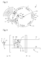
- FIGS 11 to 13 illustrate an exemplary embodiment of an escapement mechanism according to the invention, in a magnetic alternative, and where the escape wheel 3, of pivot axis D1, comprises two disks, upper 31 and lower 32, each equipped actuators 6 which are here magnetized in an axial direction parallel to D1, with first surfaces 61 at the top disc 31, second surfaces 62 at lower disc 32, first barriers 610 at upper disc 31, second barriers 620 at the lower disk 32, and on one and the other disk, the mechanical stops 9.
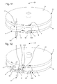
- This escape wheel 3 cooperates with a plateau balance 4, the latter is not shown on the figures 12 and 13 which show only the mobile regulator 5 that carries this plate, and which comprises a ring 50, preferably cylindrical, truncated, pivot axis D2, here parallel to D1.
- This ring 50 is magnetized in an axial direction parallel to D2.
- the ring 50 has a complementary inner abutment surface 10 and a second abutment outer abutment surface 11, connected on each side of an opening 51 by a junction surface 12, preferably sloping, and delimited on the inside by a spout. inside 13, and on the outside by an outside spout 14.
- the configuration of the sloped surfaces 12 and the spouts 13 and 14 is not symmetrical, on either side of the opening 51.
- the two sloped surfaces 12 are planar, and inclined, and each make an angle of the same orientation and substantially the same value, with the radial end of the pivot axis D2.
- the figure 12 shows the respective magnetizations of the regulator 5 and the actuators 6.
- the torque of the escape wheel 3 forces a first magnetized portion, in this case the first surface 61 or the second surface 62 respectively, of the actuator 6 arriving at the the vicinity of the ring 50, to be superimposed on or respectively under the magnetic ring 50.
- the second magnetized part then being in an interference zone, and which is formed by the first barrier 610, respectively the second barrier 620, has too much magnetic repulsion with the ring 50, the effect of which is to stop the escape wheel 3.
- the mechanical stops 9 prevent a stall of the system in case shock or excessively high torque on the escape wheel 3.
- the embodiment of the escape wheel 3 in two parts 31, 32 allows to close the magnetic path, and to avoid too great axial force on the plate.
- the figure 14 represents the same assembly, the upper disk 31 not being shown, so as to illustrate the position of the actuators 6, in particular in the zone of interference with the ring 50.
- FIGS. 15 to 35 are top views of this partial breakout that constitutes the figure 14 , and illustrate the kinematics of the system, since figure 15 , which illustrates the end of a cycle where the escape wheel 3 rotates in the clockwise direction A, under the effect of motor means 2 not shown, such as a barrel by means of a gear train.
- the balance also rotates clockwise under the spring action of the spiral spring.
- An actuator 6 interferes with the outside of the ring 50, at the second outer abutment surface 11.
- the torque of the escape wheel 3 forces the second surface 62 to be superimposed under the magnetized crown 50.
- the second barrier 620 has too much magnetic repulsion with the crown 50, the effect of which is to stop the wheel from exhaust 3, with the actuator 6 considered outside the ring 50.
- the figure 16 shows the continuation of the stroke of the pendulum clockwise, which passes through the neutral point where the return torque of the spiral spring is zero, and the second surface 62 begins to apply a time pulse to the balance by magnetic repulsion, similarly to a constant force.
- the following figures include arrows illustrating the rotations already made of the balance wheel and the escape wheel from this stage.
- the figure 17 shows the end of the hour pulse, the second surface 62 crosses the junction surface 12, and escapes the inner beak 13 which delimits it.
- the rocker releases the second surface 62 of the actuator 6, and does not oppose the passage of the second barrier 620 or stop 9.
- the escape wheel 3 can then begin to turn clockwise.
- the figure 18 shows the system at the beginning of the alternation of the balance, which rotates under the effect of the pulse in the clockwise direction H, and the rotation of the exhaust street 3.
- the actuator 6 enters the domain delimited by the 'grip of the crown 50, inside thereof.
- the figure 19 shows the arrival of an actuator 6 in interference with the inside of the ring 50, at a first internal stop complementary surface 10, the balance always rotating in clockwise direction H under the effect of the pulse,
- the torque of the escape wheel 3 forces the second surface 62 to be superimposed under the magnetized crown 50.
- the second barrier 620 has too much magnetic repulsion with the crown 50, the effect of which is to stop the wheel from exhaust 3, with the actuator 6 considered inside the ring 50.
- the pendulum continues to rotate in a clockwise direction H, up to the maximum amplitude, the escape wheel 3 still being stopped, as visible in FIG. figure 20 .
- the balance always rotates counter-clockwise AH
- the ring 50 passes behind a second actuator 6B which is kept at a standstill, behind the actuator 6A which is in the locking position on the first internal stop complementary surface 10 and waiting for his release, which will allow to apply the impulse to the pendulum, this time in the anti-clockwise direction.
- at least two actuators 6: 6A, 6B can thus remain in the inner volume of the ring 50.
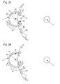
- the figure 24 shows, like the figure 17 , the end of the hour pulse, the second surface 62 crosses the junction surface 12, and escapes the inner beak 13 which delimits it.
- the rocker releases the second surface 62 of the actuator 6, and does not oppose the passage of the second barrier 620 and the stop 9.
- the escape wheel 3 can then start turning clockwise.
- the figure 25 shows the docking of an actuator 6 at the second outer abutment surface 11 of the crown 50, and, as previously, the stopping of the escape wheel 3.
- the figure 26 illustrates the end of the anti-clockwise rotation of the balance wheel, the escape wheel 3 being at a standstill.
- the figure 27 shows the passage of the pendulum clockwise H2, the escape wheel 3 is still at a standstill.
- the pendulum continues its hourly rotation.
- the figure 29 shows the start of the time pulse, the escape wheel 3 is still at a standstill.
- the amplitude of the two alternations is substantially symmetrical. It should be noted that, in the example illustrated by the figures, the pulses are not exactly given for the same angular position of the plate, an optimized escape pattern, within the range of the watchmaker of exhausts, allows to improve this situation.
- the mechanism according to the invention is designed to handle the case of a too high torque.
- the figure 30 illustrates the system for a nominal torque at the escape wheel.
- the figure 31 shows a torque at the escape wheel which is higher than the nominal: in case of exceeding the nominal torque at the escape wheel, the mechanical stops 9 of the actuator 6 avoid a stall system.
- the figure 32 shows, in this same case, the continued pivoting of the balance in a clockwise direction H, with a mechanical stop 9 bearing against the second complementary abutment surface 11 of the outer ring 50.
- figure 33 represents the moment before a so-called mechanical pulse, where the mechanical stop 9 bears on an external nose 14 which marks the nominal between the second complementary abutment surface 11 of the outer ring 50 and the junction surface 12.
- figure 34 shows the role of the inclined junction surface 12, the ring 50, which prints a mechanical type pulse in the same way as in a traditional cylinder exhaust. This makes it possible to ensure the operation of the system even if the torque is too high.
- the figure 35 shows the end of this mechanical impulse.
- the invention provides a higher efficiency than in a conventional cylinder exhaust.
- the chronometric properties of an escapement according to the invention are satisfactory.
Landscapes
- Physics & Mathematics (AREA)
- General Physics & Mathematics (AREA)
- Electromagnetism (AREA)
- Micromachines (AREA)
- Reciprocating, Oscillating Or Vibrating Motors (AREA)
- Exhaust Silencers (AREA)
Priority Applications (18)
| Application Number | Priority Date | Filing Date | Title |
|---|---|---|---|
| EP14186261.5A EP2889704B1 (de) | 2013-12-23 | 2014-09-24 | Kontaktloser Zylindrische Uhrhemmungsmechanismus |
| CH01444/14A CH709058A2 (fr) | 2013-12-23 | 2014-09-24 | Mécanisme d'échappement à cylindre d'horlogerie sans contact. |
| EP14186297.9A EP2911015B1 (de) | 2013-12-23 | 2014-09-25 | Natürliche Hemmung |
| CH01450/14A CH709061A2 (fr) | 2013-12-23 | 2014-09-25 | Mécanisme d'échappement naturel. |
| PCT/EP2014/076930 WO2015096973A2 (fr) | 2013-12-23 | 2014-12-08 | Mecanisme d'echappement a cylindre d'horlogerie sans contact |
| RU2016130266A RU2666451C2 (ru) | 2013-12-23 | 2014-12-08 | Бесконтактный цилиндрический спусковой механизм для часов |
| US15/106,433 US9746829B2 (en) | 2013-12-23 | 2014-12-08 | Contactless cylinder escapement mechanism for timepieces |
| JP2016542197A JP6236164B2 (ja) | 2013-12-23 | 2014-12-08 | タイムピース用の非接触シリンダー脱進機構 |
| CN201480070342.9A CN105849650B (zh) | 2013-12-23 | 2014-12-08 | 用于钟表的非接触式圆柱擒纵机构 |
| PCT/EP2014/077039 WO2015096979A2 (fr) | 2013-12-23 | 2014-12-09 | Echappement naturel |
| JP2016533632A JP6130603B2 (ja) | 2013-12-23 | 2014-12-09 | 自然脱進機 |
| CN201480070616.4A CN105849652B (zh) | 2013-12-23 | 2014-12-09 | 自然式擒纵机构 |
| RU2016130276A RU2660530C2 (ru) | 2013-12-23 | 2014-12-09 | Естественный спусковой механизм |
| US15/028,599 US9927773B2 (en) | 2013-12-23 | 2014-12-09 | Natural escapement |
| CN201480076123.1A CN106030422B (zh) | 2013-12-23 | 2014-12-22 | 用于调整包括磁性擒纵器的钟表机芯中的运动件的角频率的装置 |
| US15/109,066 US9715217B2 (en) | 2013-12-23 | 2014-12-22 | Device intended to control the angular speed of a train in a timepiece movement and including a magnetic escapement |
| PCT/EP2014/079036 WO2015097172A2 (fr) | 2013-12-23 | 2014-12-22 | Dispositif regulateur de la vitesse angulaire d'un mobile dans un mouvement horloger comprenant un echappement magnetique |
| EP14821180.8A EP3087435B1 (de) | 2013-12-23 | 2014-12-22 | Vorrichtung zur steuern der winkelgeschwindigkeit eines räderwerks in einem eine magnetische hemmung unfassnden uhrwerk |
Applications Claiming Priority (6)
| Application Number | Priority Date | Filing Date | Title |
|---|---|---|---|
| CH02140/13A CH709019B1 (fr) | 2013-12-23 | 2013-12-23 | Mécanisme d'échappement magnétique ou électrostatique. |
| EP13199427.9A EP2887157B1 (de) | 2013-12-23 | 2013-12-23 | Optimierte uhrhemmung |
| CH10572014 | 2014-07-11 | ||
| EP14176816 | 2014-07-11 | ||
| CH01365/14A CH709056A2 (fr) | 2013-12-23 | 2014-09-09 | Mécanisme de synchronisation d'horlogerie. |
| EP14186261.5A EP2889704B1 (de) | 2013-12-23 | 2014-09-24 | Kontaktloser Zylindrische Uhrhemmungsmechanismus |
Publications (3)
| Publication Number | Publication Date |
|---|---|
| EP2889704A2 true EP2889704A2 (de) | 2015-07-01 |
| EP2889704A3 EP2889704A3 (de) | 2016-06-29 |
| EP2889704B1 EP2889704B1 (de) | 2017-11-08 |
Family
ID=67394442
Family Applications (1)
| Application Number | Title | Priority Date | Filing Date |
|---|---|---|---|
| EP14186261.5A Active EP2889704B1 (de) | 2013-12-23 | 2014-09-24 | Kontaktloser Zylindrische Uhrhemmungsmechanismus |
Country Status (2)
| Country | Link |
|---|---|
| EP (1) | EP2889704B1 (de) |
| CH (1) | CH709058A2 (de) |
Cited By (2)
| Publication number | Priority date | Publication date | Assignee | Title |
|---|---|---|---|---|
| EP3128380A1 (de) * | 2015-08-04 | 2017-02-08 | ETA SA Manufacture Horlogère Suisse | Uhreinstellmechanismus mit magnetisch synchronisierten dreharmen |
| EP3128379A1 (de) * | 2015-08-04 | 2017-02-08 | The Swatch Group Research and Development Ltd. | Hemmung mit hemmungsrad mit feldrampen und vorrichtung zur rücklaufsicherung |
Families Citing this family (3)
| Publication number | Priority date | Publication date | Assignee | Title |
|---|---|---|---|---|
| EP3179316B1 (de) | 2015-12-10 | 2021-09-15 | Nivarox-FAR S.A. | Kontaktlose zylindrische uhrhemmung |
| EP3627242B1 (de) | 2018-09-19 | 2021-07-21 | The Swatch Group Research and Development Ltd | Optimierter magnetomechanischer uhrhemmungsmechanismus |
| EP4202563A1 (de) * | 2021-12-23 | 2023-06-28 | The Swatch Group Research and Development Ltd | Uhrwerksmechanismus mit einem magnetischen getrieberad |
Family Cites Families (3)
| Publication number | Priority date | Publication date | Assignee | Title |
|---|---|---|---|---|
| GB671360A (en) * | 1948-07-28 | 1952-05-07 | Smith & Sons Ltd S | Magnetic escapements for timepieces |
| US3183426A (en) * | 1962-02-14 | 1965-05-11 | Cons Electronics Ind | Magnetically coupled constant speed system |
| CH457295A (fr) * | 1965-07-29 | 1968-07-31 | Centre Electron Horloger | Dispositif de transformation du mouvement oscillant d'un résonateur de montre électromécanique |
-
2014
- 2014-09-24 EP EP14186261.5A patent/EP2889704B1/de active Active
- 2014-09-24 CH CH01444/14A patent/CH709058A2/fr not_active Application Discontinuation
Non-Patent Citations (1)
| Title |
|---|
| None |
Cited By (6)
| Publication number | Priority date | Publication date | Assignee | Title |
|---|---|---|---|---|
| EP3128380A1 (de) * | 2015-08-04 | 2017-02-08 | ETA SA Manufacture Horlogère Suisse | Uhreinstellmechanismus mit magnetisch synchronisierten dreharmen |
| EP3128379A1 (de) * | 2015-08-04 | 2017-02-08 | The Swatch Group Research and Development Ltd. | Hemmung mit hemmungsrad mit feldrampen und vorrichtung zur rücklaufsicherung |
| JP2017032553A (ja) * | 2015-08-04 | 2017-02-09 | ウーテーアー・エス・アー・マニファクチュール・オロロジェール・スイス | 磁気によって同期される回転アームを有する時計用調速機構 |
| US9785116B2 (en) | 2015-08-04 | 2017-10-10 | Eta Sa Manufacture Horlogere Suisse | Timepiece regulating mechanism with magnetically synchronized rotating arms |
| US10054908B2 (en) | 2015-08-04 | 2018-08-21 | The Swatch Group Research And Development Ltd | Escapement with escape wheel with field ramps and non-return |
| RU2703096C1 (ru) * | 2015-08-04 | 2019-10-15 | Эта Са Мануфактюр Орложэр Сюис | Регулирующий часовой механизм с магнитно-синхронизированными поворотными рычагами |
Also Published As
| Publication number | Publication date |
|---|---|
| EP2889704B1 (de) | 2017-11-08 |
| CH709058A2 (fr) | 2015-06-30 |
| EP2889704A3 (de) | 2016-06-29 |
Similar Documents
| Publication | Publication Date | Title |
|---|---|---|
| WO2015096973A2 (fr) | Mecanisme d'echappement a cylindre d'horlogerie sans contact | |
| EP2889704B1 (de) | Kontaktloser Zylindrische Uhrhemmungsmechanismus | |
| EP3327515B1 (de) | Sich drehender resonator mit einer flexiblen führung, der von einer freien ankerhemmung gehalten wird | |
| EP2887157B1 (de) | Optimierte uhrhemmung | |
| EP3087435B1 (de) | Vorrichtung zur steuern der winkelgeschwindigkeit eines räderwerks in einem eine magnetische hemmung unfassnden uhrwerk | |
| WO2012034810A2 (fr) | Echappement blancpain à ancre amélioré pour mouvement d'horlogerie | |
| EP3182213B1 (de) | Einstellmechanismus der mittleren geschwindigkeit in einem uhrwerk, und entsprechendes uhrwerk | |
| EP2911015B1 (de) | Natürliche Hemmung | |
| EP3327518A1 (de) | Uhr mit schaltvorrichtung für einen uhrmechanismus | |
| EP3081997A1 (de) | Magnetische stossdämpfung für welle eines uhrwerks | |
| EP2887156B1 (de) | Einstellvorrichtung | |
| EP3185083B1 (de) | Mechanischer uhrmechanismus mit einer ankerhemmung | |
| EP3182225B1 (de) | Uhr sequenzer mit durchgangsrad mit verringerter mechanischer reibung | |
| EP1272906B1 (de) | Hemmung für uhr | |
| CH711932A2 (fr) | Mécanisme séquenceur, mécanisme d'horlogerie et montre. | |
| WO2017102917A1 (fr) | Oscillateur mécanique pour pièce d'horlogerie, mécanisme de réglage comportant cet oscillateur mécanique, et mouvement d'horlogerie | |
| EP3663868A1 (de) | Uhrwerk, das ein tourbillon mit einem festen magnetischen rad umfasst | |
| CH710769A2 (fr) | Maintien magnétique d'un composant d'habillage ou de mouvement d'horlogerie. | |
| CH711965A2 (fr) | Mouvement horloger mécanique avec un échappement à ancre. | |
| EP3019916A2 (de) | Hemmung für eine uhr mit einem tourbillon ohne käfig | |
| EP1837718A1 (de) | Hemmungsvorrichtung für Uhrwerke | |
| CH703814A2 (fr) | Echappement à ancre pour mouvement d'horlogerie. | |
| CH709019A2 (fr) | Mécanisme d'échappement magnétique ou électrostatique. | |
| CH715618A2 (fr) | Mouvement d'horlogerie comportant un tourbillon avec une roue magnétique fixe. | |
| CH710128A2 (fr) | Mécanisme d'horlogerie comportant un crantage sans contact entre deux composants. |
Legal Events
| Date | Code | Title | Description |
|---|---|---|---|
| PUAI | Public reference made under article 153(3) epc to a published international application that has entered the european phase |
Free format text: ORIGINAL CODE: 0009012 |
|
| 17P | Request for examination filed |
Effective date: 20140924 |
|
| AK | Designated contracting states |
Kind code of ref document: A2 Designated state(s): AL AT BE BG CH CY CZ DE DK EE ES FI FR GB GR HR HU IE IS IT LI LT LU LV MC MK MT NL NO PL PT RO RS SE SI SK SM TR |
|
| AX | Request for extension of the european patent |
Extension state: BA ME |
|
| REG | Reference to a national code |
Ref country code: DE Ref legal event code: R079 Ref document number: 602014016825 Country of ref document: DE Free format text: PREVIOUS MAIN CLASS: G04C0003100000 Ipc: G04C0005000000 |
|
| PUAL | Search report despatched |
Free format text: ORIGINAL CODE: 0009013 |
|
| AK | Designated contracting states |
Kind code of ref document: A3 Designated state(s): AL AT BE BG CH CY CZ DE DK EE ES FI FR GB GR HR HU IE IS IT LI LT LU LV MC MK MT NL NO PL PT RO RS SE SI SK SM TR |
|
| AX | Request for extension of the european patent |
Extension state: BA ME |
|
| RIC1 | Information provided on ipc code assigned before grant |
Ipc: G04C 5/00 20060101AFI20160524BHEP Ipc: G04B 15/00 20060101ALI20160524BHEP Ipc: G04B 15/14 20060101ALI20160524BHEP Ipc: G04B 17/32 20060101ALI20160524BHEP |
|
| R17P | Request for examination filed (corrected) |
Effective date: 20170102 |
|
| RBV | Designated contracting states (corrected) |
Designated state(s): AL AT BE BG CH CY CZ DE DK EE ES FI FR GB GR HR HU IE IS IT LI LT LU LV MC MK MT NL NO PL PT RO RS SE SI SK SM TR |
|
| GRAP | Despatch of communication of intention to grant a patent |
Free format text: ORIGINAL CODE: EPIDOSNIGR1 |
|
| INTG | Intention to grant announced |
Effective date: 20170613 |
|
| GRAS | Grant fee paid |
Free format text: ORIGINAL CODE: EPIDOSNIGR3 |
|
| GRAA | (expected) grant |
Free format text: ORIGINAL CODE: 0009210 |
|
| AK | Designated contracting states |
Kind code of ref document: B1 Designated state(s): AL AT BE BG CH CY CZ DE DK EE ES FI FR GB GR HR HU IE IS IT LI LT LU LV MC MK MT NL NO PL PT RO RS SE SI SK SM TR |
|
| REG | Reference to a national code |
Ref country code: GB Ref legal event code: FG4D Free format text: NOT ENGLISH |
|
| REG | Reference to a national code |
Ref country code: CH Ref legal event code: EP Ref country code: CH Ref legal event code: NV Representative=s name: ICB INGENIEURS CONSEILS EN BREVETS SA, CH Ref country code: AT Ref legal event code: REF Ref document number: 944729 Country of ref document: AT Kind code of ref document: T Effective date: 20171115 |
|
| REG | Reference to a national code |
Ref country code: IE Ref legal event code: FG4D Free format text: LANGUAGE OF EP DOCUMENT: FRENCH |
|
| REG | Reference to a national code |
Ref country code: DE Ref legal event code: R096 Ref document number: 602014016825 Country of ref document: DE |
|
| REG | Reference to a national code |
Ref country code: NL Ref legal event code: MP Effective date: 20171108 |
|
| REG | Reference to a national code |
Ref country code: LT Ref legal event code: MG4D |
|
| REG | Reference to a national code |
Ref country code: AT Ref legal event code: MK05 Ref document number: 944729 Country of ref document: AT Kind code of ref document: T Effective date: 20171108 |
|
| PG25 | Lapsed in a contracting state [announced via postgrant information from national office to epo] |
Ref country code: NO Free format text: LAPSE BECAUSE OF FAILURE TO SUBMIT A TRANSLATION OF THE DESCRIPTION OR TO PAY THE FEE WITHIN THE PRESCRIBED TIME-LIMIT Effective date: 20180208 Ref country code: ES Free format text: LAPSE BECAUSE OF FAILURE TO SUBMIT A TRANSLATION OF THE DESCRIPTION OR TO PAY THE FEE WITHIN THE PRESCRIBED TIME-LIMIT Effective date: 20171108 Ref country code: FI Free format text: LAPSE BECAUSE OF FAILURE TO SUBMIT A TRANSLATION OF THE DESCRIPTION OR TO PAY THE FEE WITHIN THE PRESCRIBED TIME-LIMIT Effective date: 20171108 Ref country code: SE Free format text: LAPSE BECAUSE OF FAILURE TO SUBMIT A TRANSLATION OF THE DESCRIPTION OR TO PAY THE FEE WITHIN THE PRESCRIBED TIME-LIMIT Effective date: 20171108 Ref country code: NL Free format text: LAPSE BECAUSE OF FAILURE TO SUBMIT A TRANSLATION OF THE DESCRIPTION OR TO PAY THE FEE WITHIN THE PRESCRIBED TIME-LIMIT Effective date: 20171108 Ref country code: LT Free format text: LAPSE BECAUSE OF FAILURE TO SUBMIT A TRANSLATION OF THE DESCRIPTION OR TO PAY THE FEE WITHIN THE PRESCRIBED TIME-LIMIT Effective date: 20171108 |
|
| PG25 | Lapsed in a contracting state [announced via postgrant information from national office to epo] |
Ref country code: AT Free format text: LAPSE BECAUSE OF FAILURE TO SUBMIT A TRANSLATION OF THE DESCRIPTION OR TO PAY THE FEE WITHIN THE PRESCRIBED TIME-LIMIT Effective date: 20171108 Ref country code: LV Free format text: LAPSE BECAUSE OF FAILURE TO SUBMIT A TRANSLATION OF THE DESCRIPTION OR TO PAY THE FEE WITHIN THE PRESCRIBED TIME-LIMIT Effective date: 20171108 Ref country code: GR Free format text: LAPSE BECAUSE OF FAILURE TO SUBMIT A TRANSLATION OF THE DESCRIPTION OR TO PAY THE FEE WITHIN THE PRESCRIBED TIME-LIMIT Effective date: 20180209 Ref country code: HR Free format text: LAPSE BECAUSE OF FAILURE TO SUBMIT A TRANSLATION OF THE DESCRIPTION OR TO PAY THE FEE WITHIN THE PRESCRIBED TIME-LIMIT Effective date: 20171108 Ref country code: IS Free format text: LAPSE BECAUSE OF FAILURE TO SUBMIT A TRANSLATION OF THE DESCRIPTION OR TO PAY THE FEE WITHIN THE PRESCRIBED TIME-LIMIT Effective date: 20180308 Ref country code: BG Free format text: LAPSE BECAUSE OF FAILURE TO SUBMIT A TRANSLATION OF THE DESCRIPTION OR TO PAY THE FEE WITHIN THE PRESCRIBED TIME-LIMIT Effective date: 20180208 Ref country code: RS Free format text: LAPSE BECAUSE OF FAILURE TO SUBMIT A TRANSLATION OF THE DESCRIPTION OR TO PAY THE FEE WITHIN THE PRESCRIBED TIME-LIMIT Effective date: 20171108 |
|
| PG25 | Lapsed in a contracting state [announced via postgrant information from national office to epo] |
Ref country code: DK Free format text: LAPSE BECAUSE OF FAILURE TO SUBMIT A TRANSLATION OF THE DESCRIPTION OR TO PAY THE FEE WITHIN THE PRESCRIBED TIME-LIMIT Effective date: 20171108 Ref country code: CY Free format text: LAPSE BECAUSE OF FAILURE TO SUBMIT A TRANSLATION OF THE DESCRIPTION OR TO PAY THE FEE WITHIN THE PRESCRIBED TIME-LIMIT Effective date: 20171108 Ref country code: CZ Free format text: LAPSE BECAUSE OF FAILURE TO SUBMIT A TRANSLATION OF THE DESCRIPTION OR TO PAY THE FEE WITHIN THE PRESCRIBED TIME-LIMIT Effective date: 20171108 Ref country code: SK Free format text: LAPSE BECAUSE OF FAILURE TO SUBMIT A TRANSLATION OF THE DESCRIPTION OR TO PAY THE FEE WITHIN THE PRESCRIBED TIME-LIMIT Effective date: 20171108 Ref country code: EE Free format text: LAPSE BECAUSE OF FAILURE TO SUBMIT A TRANSLATION OF THE DESCRIPTION OR TO PAY THE FEE WITHIN THE PRESCRIBED TIME-LIMIT Effective date: 20171108 |
|
| REG | Reference to a national code |
Ref country code: DE Ref legal event code: R097 Ref document number: 602014016825 Country of ref document: DE |
|
| REG | Reference to a national code |
Ref country code: FR Ref legal event code: PLFP Year of fee payment: 5 |
|
| PG25 | Lapsed in a contracting state [announced via postgrant information from national office to epo] |
Ref country code: PL Free format text: LAPSE BECAUSE OF FAILURE TO SUBMIT A TRANSLATION OF THE DESCRIPTION OR TO PAY THE FEE WITHIN THE PRESCRIBED TIME-LIMIT Effective date: 20171108 Ref country code: IT Free format text: LAPSE BECAUSE OF FAILURE TO SUBMIT A TRANSLATION OF THE DESCRIPTION OR TO PAY THE FEE WITHIN THE PRESCRIBED TIME-LIMIT Effective date: 20171108 Ref country code: RO Free format text: LAPSE BECAUSE OF FAILURE TO SUBMIT A TRANSLATION OF THE DESCRIPTION OR TO PAY THE FEE WITHIN THE PRESCRIBED TIME-LIMIT Effective date: 20171108 Ref country code: SM Free format text: LAPSE BECAUSE OF FAILURE TO SUBMIT A TRANSLATION OF THE DESCRIPTION OR TO PAY THE FEE WITHIN THE PRESCRIBED TIME-LIMIT Effective date: 20171108 |
|
| PLBE | No opposition filed within time limit |
Free format text: ORIGINAL CODE: 0009261 |
|
| STAA | Information on the status of an ep patent application or granted ep patent |
Free format text: STATUS: NO OPPOSITION FILED WITHIN TIME LIMIT |
|
| PG25 | Lapsed in a contracting state [announced via postgrant information from national office to epo] |
Ref country code: MT Free format text: LAPSE BECAUSE OF FAILURE TO SUBMIT A TRANSLATION OF THE DESCRIPTION OR TO PAY THE FEE WITHIN THE PRESCRIBED TIME-LIMIT Effective date: 20171108 |
|
| 26N | No opposition filed |
Effective date: 20180809 |
|
| PG25 | Lapsed in a contracting state [announced via postgrant information from national office to epo] |
Ref country code: SI Free format text: LAPSE BECAUSE OF FAILURE TO SUBMIT A TRANSLATION OF THE DESCRIPTION OR TO PAY THE FEE WITHIN THE PRESCRIBED TIME-LIMIT Effective date: 20171108 |
|
| PG25 | Lapsed in a contracting state [announced via postgrant information from national office to epo] |
Ref country code: MC Free format text: LAPSE BECAUSE OF FAILURE TO SUBMIT A TRANSLATION OF THE DESCRIPTION OR TO PAY THE FEE WITHIN THE PRESCRIBED TIME-LIMIT Effective date: 20171108 |
|
| REG | Reference to a national code |
Ref country code: BE Ref legal event code: MM Effective date: 20180930 |
|
| REG | Reference to a national code |
Ref country code: IE Ref legal event code: MM4A |
|
| PG25 | Lapsed in a contracting state [announced via postgrant information from national office to epo] |
Ref country code: LU Free format text: LAPSE BECAUSE OF NON-PAYMENT OF DUE FEES Effective date: 20180924 |
|
| PG25 | Lapsed in a contracting state [announced via postgrant information from national office to epo] |
Ref country code: IE Free format text: LAPSE BECAUSE OF NON-PAYMENT OF DUE FEES Effective date: 20180924 |
|
| PG25 | Lapsed in a contracting state [announced via postgrant information from national office to epo] |
Ref country code: BE Free format text: LAPSE BECAUSE OF NON-PAYMENT OF DUE FEES Effective date: 20180930 |
|
| PG25 | Lapsed in a contracting state [announced via postgrant information from national office to epo] |
Ref country code: TR Free format text: LAPSE BECAUSE OF FAILURE TO SUBMIT A TRANSLATION OF THE DESCRIPTION OR TO PAY THE FEE WITHIN THE PRESCRIBED TIME-LIMIT Effective date: 20171108 |
|
| PG25 | Lapsed in a contracting state [announced via postgrant information from national office to epo] |
Ref country code: PT Free format text: LAPSE BECAUSE OF FAILURE TO SUBMIT A TRANSLATION OF THE DESCRIPTION OR TO PAY THE FEE WITHIN THE PRESCRIBED TIME-LIMIT Effective date: 20171108 |
|
| PG25 | Lapsed in a contracting state [announced via postgrant information from national office to epo] |
Ref country code: MK Free format text: LAPSE BECAUSE OF NON-PAYMENT OF DUE FEES Effective date: 20171108 Ref country code: HU Free format text: LAPSE BECAUSE OF FAILURE TO SUBMIT A TRANSLATION OF THE DESCRIPTION OR TO PAY THE FEE WITHIN THE PRESCRIBED TIME-LIMIT; INVALID AB INITIO Effective date: 20140924 |
|
| PG25 | Lapsed in a contracting state [announced via postgrant information from national office to epo] |
Ref country code: AL Free format text: LAPSE BECAUSE OF FAILURE TO SUBMIT A TRANSLATION OF THE DESCRIPTION OR TO PAY THE FEE WITHIN THE PRESCRIBED TIME-LIMIT Effective date: 20171108 |
|
| P01 | Opt-out of the competence of the unified patent court (upc) registered |
Effective date: 20230611 |
|
| PGFP | Annual fee paid to national office [announced via postgrant information from national office to epo] |
Ref country code: GB Payment date: 20230823 Year of fee payment: 10 |
|
| PGFP | Annual fee paid to national office [announced via postgrant information from national office to epo] |
Ref country code: FR Payment date: 20230822 Year of fee payment: 10 Ref country code: DE Payment date: 20230822 Year of fee payment: 10 |
|
| PGFP | Annual fee paid to national office [announced via postgrant information from national office to epo] |
Ref country code: CH Payment date: 20231001 Year of fee payment: 10 |