EP2887643B1 - Image pickup apparatus having GPS function and interval photographing function, method of controlling the same, and storage medium - Google Patents
Image pickup apparatus having GPS function and interval photographing function, method of controlling the same, and storage medium Download PDFInfo
- Publication number
- EP2887643B1 EP2887643B1 EP14198519.2A EP14198519A EP2887643B1 EP 2887643 B1 EP2887643 B1 EP 2887643B1 EP 14198519 A EP14198519 A EP 14198519A EP 2887643 B1 EP2887643 B1 EP 2887643B1
- Authority
- EP
- European Patent Office
- Prior art keywords
- time period
- image pickup
- interval
- photographing
- position information
- Prior art date
- Legal status (The legal status is an assumption and is not a legal conclusion. Google has not performed a legal analysis and makes no representation as to the accuracy of the status listed.)
- Not-in-force
Links
Images


Classifications
-
- H—ELECTRICITY
- H04—ELECTRIC COMMUNICATION TECHNIQUE
- H04N—PICTORIAL COMMUNICATION, e.g. TELEVISION
- H04N23/00—Cameras or camera modules comprising electronic image sensors; Control thereof
- H04N23/60—Control of cameras or camera modules
- H04N23/667—Camera operation mode switching, e.g. between still and video, sport and normal or high- and low-resolution modes
-
- H—ELECTRICITY
- H04—ELECTRIC COMMUNICATION TECHNIQUE
- H04N—PICTORIAL COMMUNICATION, e.g. TELEVISION
- H04N23/00—Cameras or camera modules comprising electronic image sensors; Control thereof
- H04N23/60—Control of cameras or camera modules
- H04N23/65—Control of camera operation in relation to power supply
- H04N23/651—Control of camera operation in relation to power supply for reducing power consumption by affecting camera operations, e.g. sleep mode, hibernation mode or power off of selective parts of the camera
Definitions
- the present invention relates to an image pickup apparatus having a GPS function and an interval photographing function, a method of controlling the same, and a storage medium, and more particularly to a GPS control technique and azimuth measurement used in interval photographing for performing photographing at predetermined intervals.
- Japanese Patent Laid-Open Publication No. 2007-295034 discloses a technique for starting the GPS function by detecting that photographing is to be performed outdoors based on a distance to an object and brightness of the object.
- Japanese Patent Laid-Open Publication No. 2001-257920 describing a camera system including a GPS receiver and an azimuth meter discloses a technique for automatically performing photographing when a spot set beforehand is reached.
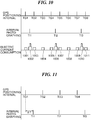
- FIG. 10 a description will be given of a GPS positioning interval and a photographing interval of interval photographing, and electric current consumption of the image pickup apparatus caused by GPS positioning and interval photographing, in the image pickup apparatus having the GPS function and the interval photographing function.
- Reference numerals TG1, TG2, ..., TG8 in FIG. 10 each denote a timing of positioning performed by the GPS.
- Reference numerals T11, T12, and T13 in FIG. 10 each denote a photographing timing of interval photographing.
- Reference numeral 1001 in FIG. 10 denotes an electric current consumption amount detected when GPS positioning is performed at TG1.
- reference numerals 1003 to 1005, 1007 to 1009, and 1011 denote electric current consumption amounts detected when GPS positioning is performed at TG2, TG3, ..., TG8, respectively.
- reference numeral 1002 denotes an electric current consumption amount detected when interval photographing is performed at T11
- reference numerals 1006 and 1010 denote electric current consumption amounts detected when interval photographing is performed at T12 and T13, respectively.
- Document US 6 995 792 B1 discloses that a positioning operation is performed to acquire a positioning result immediately before or immediately after a photographing instruction is given. GPS positioning is performed in response to a positioning start instruction (half depression of the shutter), after which the photographing instruction is issued. GPS positioning and photographing are carried out in order when an operation (full depression of the shutter) serves as both the photographing instruction and the positioning start instruction.
- Document US 2012/200715 A1 discloses an imaging apparatus includes an imaging unit configured to acquire image data, a positioning unit configured to perform positioning processing for acquiring positional information, a first control unit configured to control the positioning unit to perform the positioning processing at a first time interval, and to control an association unit to associate the positional information with the image data, and a second control unit configured to control the positioning unit to perform the positioning processing at a second time interval, and to control a generation unit to generate the log data based on the positional information, wherein the second control unit changes a time interval based on the acquisition status of the positional information.
- the present invention provides a technique for controlling an image pickup apparatus that is capable of reducing wasteful electric power consumption due to execution of a GPS function which is asynchronous to interval photographing, and adding the newest position information measured by the GPS function to an image photographed by interval photographing.
- a non-transitory computer-readable storage medium storing a computer-executable program for executing a method of controlling an image pickup apparatus as specified in claim 10.
- the present invention it is possible to reduce wasteful electric power consumption due to execution of the GPS function which is asynchronous to interval photographing, and add the newest position information measured by the GPS function to an image photographed by interval photographing.
- FIG. 1 is a schematic block diagram of an image pickup apparatus according to a first embodiment of the present invention.
- the image pickup apparatus is a camera having a GPS function and an interval photographing function, and is configured as described below.
- An image pickup section 200 includes an optical lens, a CMOS sensor, a digital image processor, and so forth, none of which are shown, and converts an analog signal input through the optical lens to digital data to thereby acquire a photographed image.
- a recording section 101 is a memory for storing data of an image photographed by the image pickup section 200.
- An operation section 102 is comprised of buttons, a cross key, a tough panel, and so forth, and receives an instruction provided by a user's operation. Operation information input from the operation section 102 is transmitted to a controller 100. Further, the operation section 102 is configured to be capable of setting photographing intervals of interval photographing, intervals of positioning and azimuth measurement performed by the GPS and an azimuth sensor, respectively, and so forth.
- a display section 103 is implemented by e.g. a liquid crystal panel or an organic EL panel, and displays various information, such as an operation screen and a photographed image, based on an instruction from the controller 100.
- a GPS module 110 which is a position acquisition unit, and the azimuth sensor, denoted by reference numeral 111, whereby positioning information measured by the GPS module 110 and azimuth information measured by the azimuth sensor 111 are input to the controller 100.
- the controller 100 which is connected to the above-mentioned components, performs various controls, including the control of image pickup and display operations performed by the image pickup section 200, the control of the timing of interval photographing, and the control of the timing of positioning performed by the GPS.
- FIG. 2 is a flowchart of the interval photographing control process performed by the image pickup apparatus 1 according to the first embodiment.
- the present photographing control process is realized by the controller 100 which reads out a program stored in a nonvolatile memory, not shown, loads the read program into a RAM, not shown, and executes the program. Processes, described hereinafter, represented by other flowcharts are also realized in the similar manner. Further, the present photographing control process is started when the image pickup apparatus 1 is shifted to an interval photographing mode according to a user's operation.
- the controller 100 receives the settings of the interval (TG) of positioning performed by the GPS module 110, the photographing interval (TI) of interval photographing, and the number of times of execution of interval photographing.
- the controller 100 may be configured to also receive the setting of the intervals of measurement performed by the azimuth sensor 111, and thereby record an image including the azimuth information output from the azimuth sensor 111 when photographing the image, described hereinafter, so as to control the intervals of measurement performed by the azimuth sensor 111 and reduce power consumption due to the azimuth measurement.
- the position acquisition unit of the present invention may include the function of an azimuth detection unit realized by the azimuth sensor.
- step S1003 the controller 100 determines whether or not interval photographing of which the photographing interval (TI) is set on the operation section 102 is set enabled in the enable/disable setting which is separately set in advance. If it is determined that interval photographing is set enabled, the process proceeds to a step S1004, whereas if not, the process proceeds to a step S1005.
- the controller 100 performs a TG resetting process for resetting the GPS positioning interval (TG).
- TG GPS positioning interval
- the controller 100 starts a GPS positioning interval timer incorporated in the controller 100 based on the GPS positioning intervals (TG) reset in the step S1004.
- step S1006 the controller 100 determines whether or not the counted time has reached a set GPS positioning time, and if the counted time has reached the set GPS positioning time, the process proceeds to a step S1030, and whereas if not, the process proceeds to a step S1007.
- step S1030 the controller 100 performs positioning by the GPS module 110, and then proceeds to the step S1007.
- a time period required for performing GPS positioning at this time is stored in the recording section 101.
- the controller 100 determines whether or not an operation for starting interval photographing has been performed on the operation section 102. If it is determined that the interval photographing-starting operation has been performed, the controller 100 starts a timer incorporated in the controller 100, for counting the photographing interval of interval photographing, and proceeds to a step S1008, whereas if not, the process proceeds to a step S1020.
- step S1020 the controller 100 determines whether or not a release operation has been performed on the operation section 102. If it is determined that the release operation has been performed, the process proceeds to a step S1021, whereas if not, the process returns to the step S1002.
- the controller 100 photographs an object using the image pickup section 200, and records the photographed image including the positioning information output from the GPS module 110, in the recording section 101. Then, the process returns to the step S1002.
- the controller 100 determines whether or not time counted by the timer for counting the photographing interval of interval photographing, started in the step S1007, has reached an interval photographing time (the photographing interval (TI) has elapsed). If it is determined that the counted time has reached the interval photographing time, the process proceeds to a step S1040, whereas if not, the process proceeds to a step S1009.
- the controller 100 photographs an object using the image pickup section 200, and records the photographed image including the positioning information output from the GPS module 110, in the recording section 101. Further, the controller 100 updates the number of times of execution of interval photographing.
- the controller 100 performs a TG phase adjustment process for setting a phase adjusting positioning interval so as to synchronize the timing of positioning performed by the GPS module 110 and the photographing timing of interval photographing, and then proceeds to a step S1010.
- the TG phase adjustment process in the step S1009 will be described in detail hereinafter.
- step S1010 the controller 100 determines whether or not the counted time has reached the GPS positioning time, and if it is determined that the counted time has reached the GPS positioning time, the process proceeds to a step S1050, whereas if not, the process proceeds to a step S1011.
- step S1050 the controller 100 performs positioning by the GPS module 110, and then proceeds to the step S1011.
- the controller 100 determines whether or not interval photographing is canceled on the operation section 102, or if the number of times of execution of interval photographing has reached the set number of times. If interval photographing is canceled, or if the number of times of execution of interval photographing has reached the set number of times, the process returns to the step S1002, whereas if not, the process returns to the step S1008.
- FIG. 3 is a flowchart of the TG resetting process performed in the step S1004 in FIG. 2 , for resetting the interval (TG) of positioning performed by the GPS module 110.
- a step S2002 the controller 100 determines whether or not the current mode is a mode for synchronizing the intervals of positioning performed by the GPS module 110 and the photographing intervals of interval photographing. If it is determined that the current mode is the mode for synchronizing the GPS positioning intervals and the photographing intervals, the process proceeds to a step S2003, whereas if not, the process proceeds to a step S2040.
- the current mode is a mode for recording results of GPS positioning in the recording section 101 at fixed intervals
- the priority is given to GPS positioning performed at the positioning intervals (TG) set in the step S1002 in FIG. 2 , and hence the process proceeds to the step S2040.
- the mode for recording results of GPS positioning at fixed intervals in the recording section 101 is a so-called logging mode for performing the function of generating a user's movement track.
- the image pickup apparatus 1 in the present embodiment has the function of generating a user's movement track using the GPS module 110 (so-called logging function).
- the GPS module 110 When the logging function is enabled, the GPS module 110 records position information and date-and-time information as a set of information whenever a predetermined time elapses, to thereby generate a log file.
- the user can set an interval of recording the position information during the use of the logging function of the GPS module 110 e.g. by menu operation.
- the controller 100 gives priority to positioning, and does not execute the operation for synchronizing the intervals of positioning with the photographing intervals of interval photographing. This is because, when a user uses the logging function, the user may desire to record the position information indicative of the movement track also during the photographing intervals of interval photographing.
- step S2040 the process returns without changing the GPS positioning interval (TG) set in the step S1002 in FIG. 2 . Further, the phase adjusting positioning interval, described hereinafter, is not set, either.
- the controller 100 determines whether or not the photographing interval (TI) of interval photographing set in the step S1002 in FIG. 2 is longer than a validity period of GPS satellite position information.
- the GPS satellite position information generally has two types (almanac and ephemeris) of a validity period, and an almanac validity period (validity period of almanac data) is approximately one week, and an ephemeris validity period (validity period of ephemeris data) is approximately one hour and a half to four hours.
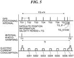
- the process proceeds to a step S2004, whereas if not, the process proceeds to a step S2020. That is, in a case where the validity period of GPS satellite position information expires during the photographing interval (TI) of interval photographing, as shown in FIG. 5 which is a timing diagram showing GPS positioning intervals, photographing intervals of interval photographing, and electric current consumption, if the validity period of the GPS satellite position information expires during the photographing interval (TI) of interval photographing, the process proceeds to the step S2004.
- the controller 100 sets the interval (TG) of positioning performed by the GPS module 110 to the photographing interval (TI) of interval photographing, and sets the phase adjusting positioning interval (TG_P) as expressed by the following equation (1), whereafter the process returns. More specifically, if the set photographing interval (TI) is not longer than the validity period of the GPS satellite position information, the controller 100 changes the GPS positioning interval TG to TG' as shown in FIG. 7 which is a timing diagram showing the GPS positioning intervals and the photographing intervals of interval photographing, in a case where the GPS positioning interval is changed by the TG resetting process in FIG. 3 , whereby the GPS positioning interval is caused to be synchronized with the photographing interval of interval photographing. Therefore, the timings become as shown in FIG.
- the controller 100 compares the sum of power consumption (sum of power consumptions 5001 to 5007 appearing in FIG. 5 ) in a case where the GPS module 110 performs positioning N times for each validity period of the GPS satellite position information and performs positioning at a time point TG_S1030 earlier than the time point of execution of interval photographing, within the photographing interval (TI) of interval photographing and then the interval photographing is performed in a manner synchronized therewith, and the power consumption (power consumption 6001 in FIG.
- the GPS module 110 performs positioning after the GPS is cold-started immediately before photographing within the TI period (positioning performed from a state in which the satellite position information is invalid) and the interval photographing is performed in a manner synchronized therewith, as shown in FIG. 6 . Then, if the power consumption from the cold start is larger than the sum of power consumptions, the process proceeds to a step S2005, whereas if the power consumption from the cold start is not larger than the sum of power consumptions, the process proceeds to a step S2030.
- the number of times N of execution of positioning is set based on the definite satellite position information validity period and photographing interval (TI), such that the following expression (2) is satisfied: satellite position information validity period ⁇ N + TG _ S 1030 ⁇ TI ⁇ satellite position information validity period ⁇ N + 1
- the start of GPS is referred to as the hot start, and a time period required in this case for performing positioning is several seconds.
- the GPS start is referred to as the warm start, and a time period required in this case for performing positioning is several seconds to several tens of seconds.
- the GPS start is referred to as the cold start, and a time period required in this case for performing positioning is several tens of seconds to several minutes.
- the controller 100 sets the interval (TG) of positioning to be performed by the GPS module 110 to the satellite position information validity period. Further, the controller 100 sets the number of times N of execution of positioning described above in the step S2004, and sets the phase adjusting positioning interval (TG_P) for terminating GPS positioning immediately before interval photographing, which is calculated by the following equation (3), followed by returning.
- the timings are as shown in FIG. 5 .
- phase adjusting positioning interval TG _ P TI ⁇ TG ⁇ N ⁇ time period required for GPS positioning , which is stored in S 1030 TG _ S 1030
- the controller 100 sets the interval (TG) of positioning by the GPS module 110 to the photographing interval (TI) of interval photographing, and sets the phase adjusting positioning interval (TG_P), which is calculated by the following equation (4), followed by returning.
- the timings are as shown in FIG. 6 .
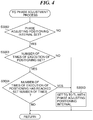
- FIG. 4 is a flowchart of the TG phase adjustment process performed in the step S1009 in FIG. 2 , for setting the phase adjusting positioning interval.
- a step S3002 the controller 100 determines whether or not the phase adjusting positioning interval (TG_P) is set in the TG resetting process in FIG. 3 for setting the GPS positioning interval (TG). If it is determined that the phase adjusting positioning interval (TG_P) is set, the process proceeds to a step S3003, whereas if not, the process returns.
- step S3003 the controller 100 determines whether or not the number of times of execution of GPS positioning is set, and if it is determined that the number of times of execution of GPS positioning is set, the process proceeds to a step S3004, whereas if not, the process proceeds to a step S3010.
- the controller 100 determines whether or not the number of times of execution of GPS positioning in the step S1050 in FIG. 2 has reached the set number of times, and if the number of times of execution has reached the set number of times, the process proceeds to the step S3010, whereas if not, the process returns.
- the controller 100 sets the GPS positioning interval TG to the photographing interval TI, and also sets the phase adjusting positioning interval (TG_P) calculated in the TG resetting process in FIG. 3 for resetting the GPS positioning interval, followed by returning.
- TG_P phase adjusting positioning interval
- the GPS positioning interval is changed to be synchronized with the interval of photographing performed by an interval photographing unit.
- interval photographing and GPS positioning are simultaneously performed, whereby it is possible to reduce wasteful electric power consumption due to GPS positioning asynchronous to interval photographing.
- GPS positioning is finished immediately before interval photographing by setting the positioning interval adjusted with reference to the start of interval photographing, and hence it is possible to add the newest position information measured by the GPS to an image photographed by interval photographing.
- the azimuth measurement may be performed by the azimuth sensor 111 at the same timing as the timing of GPS positioning to thereby control the intervals of measurement performed by the azimuth sensor 111 and power consumption due to the azimuth measurement. Further, only the intervals of measurement performed by the azimuth sensor 111 may be controlled in place of GPS positioning to thereby reduce power consumption due to the azimuth measurement performed by the azimuth sensor 111. That is, the position acquisition unit of the present invention may include the function of the azimuth detection unit realized by the azimuth sensor.
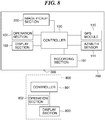
- FIG. 8 is a schematic block diagram of the image pickup apparatus according to the second embodiment.
- the controller 100 is connected to an interval photographing accessory 800 via a connection terminal 300.
- the interval photographing accessory 800 is an accessory unit connected to the image pickup apparatus 700 to control interval photographing, and is configured to be removably attached to the image pickup apparatus 700.
- the interval photographing accessory 800 is comprised of a controller 801 which is different from the controller 100 included in the image pickup apparatus 700, an operation section 802, and a display section 803.
- the operation section 802 is comprised of buttons, etc., and receives an instruction input by a user's operation.
- the display section 803 is implemented by e.g. a liquid crystal panel, and displays various information, such as an operation screen.
- the interval (TI) set by the operation section 802 is input from the controller 801 to the controller 100 of the image pickup apparatus 700 via the connection terminal 300 as a release signal.
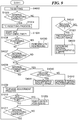
- FIG. 9 is a flowchart of the interval photographing control process performed by the image pickup apparatus 700 according to the second embodiment.
- the present interval photographing control process is started when the mode is changed to the interval photographing mode according to a user's operation.
- the controller 100 receives the setting of the interval of positioning to be performed by the GPS module 110 via the operation section 102.
- the setting of the photographing interval (TI) of interval photographing is received by the interval photographing accessory 800.
- the controller 100 may be configured to also receive the setting of the intervals of measurement performed by the azimuth sensor 111, and thereby record an image including the azimuth information output from the azimuth sensor 111 when photographing the image, referred to hereinafter, so as to control the intervals of measurement performed by the azimuth sensor 111 and reduce power consumption due to the azimuth measurement.
- a step S4007 the controller 100 determines whether or not interval photographing has been started, according to determination of whether or not it is during interval photographing in a step S4022, referred to hereinafter. If it is determined that interval photographing has been started, the process proceeds to a step S4008, whereas if not, the process proceeds to a step S4020.
- the controller 100 determines whether or not the release operation has been performed from one of the operation section 102 of the image pickup device 700 and the operation section 802 of the interval photographing accessory 800. If it is determined that the release operation has been performed, the process proceeds to the step S1021, whereas if not, the process returns to the step S4002.
- the controller 100 measures the intervals of the release operation started in the step S1021, and if the release operation is performed at fixed intervals, it is determined that it is during interval photographing, and sets the photographing interval (TI) of interval photographing. Further, the controller 100 starts the timer incorporated in the controller 100, for counting the photographing interval of interval photographing, and returns to the step S4002.
- the controller 100 determines whether or not the timer started in the step S4022 has reached the interval photographing time (the photographing interval (TI) has elapsed). If it is determined that the timer has reached the interval photographing time, the process proceeds to a step S4040, whereas if not, the process proceeds to the step S1009.
- the controller 100 determines whether or not the release operation has been performed from one of the operation section 102 of the image pickup device 700 and the operation section 802 of the interval photographing accessory 800. If it is determined that the release operation has been performed, the process proceeds to a step S4041, whereas if not, the process proceeds to a step S4042.
- step S4041 similarly to the step S1021, the controller 100 photographs the object using the image pickup section 200, records the image including the positioning information output form the GPS module 110, in the recording section 101, and proceeds to the step S1009.
- step S4042 since the release signal is not input from the interval photographing accessory 800 at a repetition period of the photographing interval TI, the controller 100 determines that interval photographing is terminated, and cancels interval photographing, and the process proceeds to the step S1009.
- the GPS positioning interval is changed such that it is synchronized with the photographing interval of photographing performed by the interval photographing unit.
- the release operation is performed by the external accessory.
- GPS positioning is finished immediately before interval photographing by setting the positioning interval adjusted after the start of interval photographing and hence it is possible to add the newest position information measured by GPS to an image photographed by interval photographing.
- the azimuth measurement may be performed by the azimuth sensor 111 at the same timing as the timing of GPS positioning to thereby control the intervals of measurement performed by the azimuth sensor 111 and power consumption due to the azimuth measurement. Further, only the intervals of measurement performed by the azimuth sensor 111 may be controlled in place of GPS positioning to thereby reduce power consumption due to the azimuth measurement performed by the azimuth sensor 111.
- the GPS positioning interval is synchronized with the photographing interval of interval photographing in a case where the set photographing interval is not smaller than the set positioning interval.
- the GPS positioning interval may be synchronized with the photographing interval of interval photographing even when the set photographing interval is smaller than the set positioning interval.
- the positioning interval may be changed, for example, in the following manner: half the time of the photographing interval is set as the positioning interval.
- the power saving effects can also be acquired by using this method. That is, a time which is longer than the original positioning interval and is acquired by equally dividing the photographing interval may be set as the positioning interval.
- the release operation may be received even during interval photographing. More specifically, the release operation may be received even when the steps S1008 to S1011 and S1050 in FIG. 2 are being executed. Note that in the step S1040, since photographing processing is being executed, higher priority is set to processing which has been already executed.
- the controller 100 may control image pickup to be performed separately from image pickup executed at each photographing interval of interval photographing while maintaining the interval photographing mode. Alternatively, when the release operation is received, the controller 100 may terminate the interval photographing mode, and shift the mode to the still image photographing mode to perform image pickup. This makes it possible to reduce possibility of missing a shutter chance. Further, the newest position information, which has been acquired, of all items of position information acquired at timings synchronized with the photographing interval of interval photographing, is added to the image which is acquired by the above-mentioned manner.
- Embodiment(s) of the present invention can also be realized by a computer of a system or apparatus that reads out and executes computer executable instructions (e.g., one or more programs) recorded on a storage medium (which may also be referred to more fully as a 'non-transitory computer-readable storage medium') to perform the functions of one or more of the above-described embodiment(s) and/or that includes one or more circuits (e.g., application specific integrated circuit (ASIC)) for performing the functions of one or more of the above-described embodiment(s), and by a method performed by the computer of the system or apparatus by, for example, reading out and executing the computer executable instructions from the storage medium to perform the functions of one or more of the above-described embodiment(s) and/or controlling the one or more circuits to perform the functions of one or more of the above-described embodiment(s).
- computer executable instructions e.g., one or more programs
- a storage medium which may also be referred to more fully as
- the computer may comprise one or more processors (e.g., central processing unit (CPU), micro processing unit (MPU)) and may include a network of separate computers or separate processors to read out and execute the computer executable instructions.
- the computer executable instructions may be provided to the computer, for example, from a network or the storage medium.
- the storage medium may include, for example, one or more of a hard disk, a random-access memory (RAM), a read only memory (ROM), a storage of distributed computing systems, an optical disk (such as a compact disc (CD), digital versatile disc (DVD), or Blu-ray Disc (BD)TM), a flash memory device, a memory card, and the like.
Landscapes
- Engineering & Computer Science (AREA)
- Multimedia (AREA)
- Signal Processing (AREA)
- Studio Devices (AREA)
- Television Signal Processing For Recording (AREA)
- Position Fixing By Use Of Radio Waves (AREA)
Applications Claiming Priority (1)
| Application Number | Priority Date | Filing Date | Title |
|---|---|---|---|
| JP2013262807A JP6296780B2 (ja) | 2013-12-19 | 2013-12-19 | 撮像装置およびその制御方法、並びにプログラム |
Publications (2)
| Publication Number | Publication Date |
|---|---|
| EP2887643A1 EP2887643A1 (en) | 2015-06-24 |
| EP2887643B1 true EP2887643B1 (en) | 2019-09-04 |
Family
ID=52347085
Family Applications (1)
| Application Number | Title | Priority Date | Filing Date |
|---|---|---|---|
| EP14198519.2A Not-in-force EP2887643B1 (en) | 2013-12-19 | 2014-12-17 | Image pickup apparatus having GPS function and interval photographing function, method of controlling the same, and storage medium |
Country Status (4)
| Country | Link |
|---|---|
| US (1) | US9667866B2 (enExample) |
| EP (1) | EP2887643B1 (enExample) |
| JP (1) | JP6296780B2 (enExample) |
| CN (1) | CN104735345B (enExample) |
Families Citing this family (4)
| Publication number | Priority date | Publication date | Assignee | Title |
|---|---|---|---|---|
| JP5896181B2 (ja) * | 2014-01-23 | 2016-03-30 | カシオ計算機株式会社 | 撮像装置、撮像制御方法、及びプログラム |
| EP3637756B1 (en) * | 2017-05-18 | 2022-02-16 | Sony Group Corporation | Image capture device and image capture method |
| CN109922423B (zh) * | 2017-12-11 | 2021-09-07 | 斑马智行网络(香港)有限公司 | 一种定位方法、装置、终端设备和存储介质 |
| CN116049464B (zh) * | 2022-08-05 | 2023-10-20 | 荣耀终端有限公司 | 一种图像整理方法及电子设备 |
Family Cites Families (22)
| Publication number | Priority date | Publication date | Assignee | Title |
|---|---|---|---|---|
| JP2001094916A (ja) * | 1999-09-17 | 2001-04-06 | Sony Corp | 情報処理方法および装置、並びにプログラム格納媒体 |
| US6995792B1 (en) | 1999-09-30 | 2006-02-07 | Casio Computer Co., Ltd. | Camera with positioning capability |
| JP3915344B2 (ja) * | 1999-10-25 | 2007-05-16 | カシオ計算機株式会社 | カメラ装置及び撮影位置記憶方法 |
| JP4404279B2 (ja) * | 1999-09-30 | 2010-01-27 | カシオ計算機株式会社 | カメラ装置 |
| JP4239128B2 (ja) * | 2000-03-13 | 2009-03-18 | 富士フイルム株式会社 | カメラシステム |
| JP2006177780A (ja) * | 2004-12-22 | 2006-07-06 | Hitachi Cable Ltd | 光ファイバ温度センサ、温度センサシート及び温度測定方法 |
| JP2006259701A (ja) * | 2005-02-16 | 2006-09-28 | Nikon Corp | 間欠撮影装置とこれを有する顕微鏡システム |
| JP2006339723A (ja) * | 2005-05-31 | 2006-12-14 | Funai Electric Co Ltd | 電子スチルカメラ |
| JP4356688B2 (ja) | 2005-12-07 | 2009-11-04 | ソニー株式会社 | 撮像装置、およびデータ記録方法、データ表示制御方法、並びにコンピュータ・プログラム |
| JP4525578B2 (ja) * | 2005-12-07 | 2010-08-18 | ソニー株式会社 | 撮像装置、およびgps制御方法、並びにコンピュータ・プログラム |
| JP4889349B2 (ja) * | 2006-04-05 | 2012-03-07 | オリンパス株式会社 | 電子スチルカメラ及び画像処理装置 |
| JP4751758B2 (ja) * | 2006-04-20 | 2011-08-17 | オリンパスイメージング株式会社 | 再生装置 |
| KR101446775B1 (ko) * | 2008-04-04 | 2014-10-01 | 삼성전자주식회사 | Gps를 내장한 디지털 카메라 및 그 제어방법 |
| JP5375391B2 (ja) * | 2008-07-25 | 2013-12-25 | 株式会社ニコン | 電子機器に取り付ける外部アクセサリ、およびシステム |
| WO2010029846A1 (ja) * | 2008-09-12 | 2010-03-18 | 株式会社ニコン | 撮影装置 |
| KR20110040248A (ko) * | 2009-10-13 | 2011-04-20 | 삼성전자주식회사 | 디지털 영상 처리기에서 소비 전력 저감 장치 및 방법 |
| JP2011141144A (ja) * | 2010-01-06 | 2011-07-21 | Sony Corp | 電子機器、測位デバイス、情報処理方法およびプログラム |
| JP2011160026A (ja) * | 2010-01-29 | 2011-08-18 | Panasonic Corp | 撮像システム |
| US8588870B1 (en) * | 2010-10-15 | 2013-11-19 | Sprint Spectrum L.P. | Method and system for reducing resource consumption to extend battery life based on an estimated time to destination |
| JP2012154872A (ja) * | 2011-01-28 | 2012-08-16 | Sanyo Electric Co Ltd | 電子機器 |
| JP5762030B2 (ja) | 2011-02-04 | 2015-08-12 | キヤノン株式会社 | 撮像装置、及びその制御方法とそのプログラム |
| WO2013084337A1 (ja) | 2011-12-08 | 2013-06-13 | キヤノン株式会社 | 撮像装置、およびその制御方法、プログラム |
-
2013
- 2013-12-19 JP JP2013262807A patent/JP6296780B2/ja not_active Expired - Fee Related
-
2014
- 2014-12-15 US US14/570,560 patent/US9667866B2/en not_active Expired - Fee Related
- 2014-12-17 EP EP14198519.2A patent/EP2887643B1/en not_active Not-in-force
- 2014-12-19 CN CN201410805571.2A patent/CN104735345B/zh not_active Expired - Fee Related
Non-Patent Citations (1)
| Title |
|---|
| None * |
Also Published As
| Publication number | Publication date |
|---|---|
| US20150181121A1 (en) | 2015-06-25 |
| US9667866B2 (en) | 2017-05-30 |
| JP6296780B2 (ja) | 2018-03-20 |
| JP2015119401A (ja) | 2015-06-25 |
| CN104735345A (zh) | 2015-06-24 |
| EP2887643A1 (en) | 2015-06-24 |
| CN104735345B (zh) | 2018-03-20 |
Similar Documents
| Publication | Publication Date | Title |
|---|---|---|
| JP5187399B2 (ja) | 撮影装置 | |
| EP2887643B1 (en) | Image pickup apparatus having GPS function and interval photographing function, method of controlling the same, and storage medium | |
| CN112383675B (zh) | 一种时间同步方法、装置及终端设备 | |
| US20110063461A1 (en) | Image sensing apparatus and system | |
| US10254410B2 (en) | Positioning control method, positioning device and storage medium | |
| JP2019124646A (ja) | 電子機器、測位制御方法及びプログラム | |
| JP5433930B2 (ja) | カメラ、およびカメラシステム | |
| JP2012205038A (ja) | 画像表示装置及び画像表示方法 | |
| JP2006339723A (ja) | 電子スチルカメラ | |
| US9030567B2 (en) | Image capture apparatus and setting time information | |
| JP5482169B2 (ja) | デジタルカメラ、及びメッセージ表示方法、プログラム | |
| US10587838B2 (en) | Image processing apparatus capable of acquiring position information, control method for the image processing apparatus, and recording medium | |
| JP2012085223A (ja) | 撮影条件生成装置、撮像装置および撮影条件生成プログラム | |
| US10425581B2 (en) | Recording apparatus, control method of recording apparatus, and storage medium | |
| JP2017021593A (ja) | 画像分類装置、画像分類方法、及びプログラム | |
| JP6947250B2 (ja) | 電子機器、測位制御方法及びプログラム | |
| JP2010038681A (ja) | 電子機器 | |
| JP2011044990A (ja) | 撮影装置 | |
| JP2007281874A (ja) | デジタルカメラ | |
| JP2010041170A (ja) | 画像記録装置 | |
| JP5858620B2 (ja) | 撮像装置、及びその制御方法とそのプログラム | |
| JP2023132404A (ja) | 記録装置、撮影装置、時刻設定制御方法及びプログラム | |
| JP2015045580A (ja) | 電子機器 | |
| JP2008067322A (ja) | 撮像装置、撮像装置の制御方法、制御プログラムおよび記憶媒体 | |
| JP2011253001A (ja) | 撮像装置、撮影方法、及びプログラム |
Legal Events
| Date | Code | Title | Description |
|---|---|---|---|
| PUAI | Public reference made under article 153(3) epc to a published international application that has entered the european phase |
Free format text: ORIGINAL CODE: 0009012 |
|
| 17P | Request for examination filed |
Effective date: 20141217 |
|
| AK | Designated contracting states |
Kind code of ref document: A1 Designated state(s): AL AT BE BG CH CY CZ DE DK EE ES FI FR GB GR HR HU IE IS IT LI LT LU LV MC MK MT NL NO PL PT RO RS SE SI SK SM TR |
|
| AX | Request for extension of the european patent |
Extension state: BA ME |
|
| R17P | Request for examination filed (corrected) |
Effective date: 20160104 |
|
| RBV | Designated contracting states (corrected) |
Designated state(s): AL AT BE BG CH CY CZ DE DK EE ES FI FR GB GR HR HU IE IS IT LI LT LU LV MC MK MT NL NO PL PT RO RS SE SI SK SM TR |
|
| STAA | Information on the status of an ep patent application or granted ep patent |
Free format text: STATUS: EXAMINATION IS IN PROGRESS |
|
| 17Q | First examination report despatched |
Effective date: 20180109 |
|
| GRAP | Despatch of communication of intention to grant a patent |
Free format text: ORIGINAL CODE: EPIDOSNIGR1 |
|
| STAA | Information on the status of an ep patent application or granted ep patent |
Free format text: STATUS: GRANT OF PATENT IS INTENDED |
|
| INTG | Intention to grant announced |
Effective date: 20190319 |
|
| GRAS | Grant fee paid |
Free format text: ORIGINAL CODE: EPIDOSNIGR3 |
|
| GRAA | (expected) grant |
Free format text: ORIGINAL CODE: 0009210 |
|
| STAA | Information on the status of an ep patent application or granted ep patent |
Free format text: STATUS: THE PATENT HAS BEEN GRANTED |
|
| AK | Designated contracting states |
Kind code of ref document: B1 Designated state(s): AL AT BE BG CH CY CZ DE DK EE ES FI FR GB GR HR HU IE IS IT LI LT LU LV MC MK MT NL NO PL PT RO RS SE SI SK SM TR |
|
| REG | Reference to a national code |
Ref country code: GB Ref legal event code: FG4D |
|
| REG | Reference to a national code |
Ref country code: CH Ref legal event code: EP |
|
| REG | Reference to a national code |
Ref country code: AT Ref legal event code: REF Ref document number: 1177011 Country of ref document: AT Kind code of ref document: T Effective date: 20190915 |
|
| REG | Reference to a national code |
Ref country code: DE Ref legal event code: R096 Ref document number: 602014052888 Country of ref document: DE |
|
| REG | Reference to a national code |
Ref country code: IE Ref legal event code: FG4D |
|
| REG | Reference to a national code |
Ref country code: NL Ref legal event code: MP Effective date: 20190904 |
|
| REG | Reference to a national code |
Ref country code: LT Ref legal event code: MG4D |
|
| PG25 | Lapsed in a contracting state [announced via postgrant information from national office to epo] |
Ref country code: HR Free format text: LAPSE BECAUSE OF FAILURE TO SUBMIT A TRANSLATION OF THE DESCRIPTION OR TO PAY THE FEE WITHIN THE PRESCRIBED TIME-LIMIT Effective date: 20190904 Ref country code: BG Free format text: LAPSE BECAUSE OF FAILURE TO SUBMIT A TRANSLATION OF THE DESCRIPTION OR TO PAY THE FEE WITHIN THE PRESCRIBED TIME-LIMIT Effective date: 20191204 Ref country code: LT Free format text: LAPSE BECAUSE OF FAILURE TO SUBMIT A TRANSLATION OF THE DESCRIPTION OR TO PAY THE FEE WITHIN THE PRESCRIBED TIME-LIMIT Effective date: 20190904 Ref country code: SE Free format text: LAPSE BECAUSE OF FAILURE TO SUBMIT A TRANSLATION OF THE DESCRIPTION OR TO PAY THE FEE WITHIN THE PRESCRIBED TIME-LIMIT Effective date: 20190904 Ref country code: FI Free format text: LAPSE BECAUSE OF FAILURE TO SUBMIT A TRANSLATION OF THE DESCRIPTION OR TO PAY THE FEE WITHIN THE PRESCRIBED TIME-LIMIT Effective date: 20190904 Ref country code: NO Free format text: LAPSE BECAUSE OF FAILURE TO SUBMIT A TRANSLATION OF THE DESCRIPTION OR TO PAY THE FEE WITHIN THE PRESCRIBED TIME-LIMIT Effective date: 20191204 |
|
| PG25 | Lapsed in a contracting state [announced via postgrant information from national office to epo] |
Ref country code: RS Free format text: LAPSE BECAUSE OF FAILURE TO SUBMIT A TRANSLATION OF THE DESCRIPTION OR TO PAY THE FEE WITHIN THE PRESCRIBED TIME-LIMIT Effective date: 20190904 Ref country code: ES Free format text: LAPSE BECAUSE OF FAILURE TO SUBMIT A TRANSLATION OF THE DESCRIPTION OR TO PAY THE FEE WITHIN THE PRESCRIBED TIME-LIMIT Effective date: 20190904 Ref country code: LV Free format text: LAPSE BECAUSE OF FAILURE TO SUBMIT A TRANSLATION OF THE DESCRIPTION OR TO PAY THE FEE WITHIN THE PRESCRIBED TIME-LIMIT Effective date: 20190904 Ref country code: GR Free format text: LAPSE BECAUSE OF FAILURE TO SUBMIT A TRANSLATION OF THE DESCRIPTION OR TO PAY THE FEE WITHIN THE PRESCRIBED TIME-LIMIT Effective date: 20191205 Ref country code: AL Free format text: LAPSE BECAUSE OF FAILURE TO SUBMIT A TRANSLATION OF THE DESCRIPTION OR TO PAY THE FEE WITHIN THE PRESCRIBED TIME-LIMIT Effective date: 20190904 |
|
| REG | Reference to a national code |
Ref country code: AT Ref legal event code: MK05 Ref document number: 1177011 Country of ref document: AT Kind code of ref document: T Effective date: 20190904 |
|
| PG25 | Lapsed in a contracting state [announced via postgrant information from national office to epo] |
Ref country code: NL Free format text: LAPSE BECAUSE OF FAILURE TO SUBMIT A TRANSLATION OF THE DESCRIPTION OR TO PAY THE FEE WITHIN THE PRESCRIBED TIME-LIMIT Effective date: 20190904 Ref country code: PL Free format text: LAPSE BECAUSE OF FAILURE TO SUBMIT A TRANSLATION OF THE DESCRIPTION OR TO PAY THE FEE WITHIN THE PRESCRIBED TIME-LIMIT Effective date: 20190904 Ref country code: IT Free format text: LAPSE BECAUSE OF FAILURE TO SUBMIT A TRANSLATION OF THE DESCRIPTION OR TO PAY THE FEE WITHIN THE PRESCRIBED TIME-LIMIT Effective date: 20190904 Ref country code: EE Free format text: LAPSE BECAUSE OF FAILURE TO SUBMIT A TRANSLATION OF THE DESCRIPTION OR TO PAY THE FEE WITHIN THE PRESCRIBED TIME-LIMIT Effective date: 20190904 Ref country code: AT Free format text: LAPSE BECAUSE OF FAILURE TO SUBMIT A TRANSLATION OF THE DESCRIPTION OR TO PAY THE FEE WITHIN THE PRESCRIBED TIME-LIMIT Effective date: 20190904 Ref country code: RO Free format text: LAPSE BECAUSE OF FAILURE TO SUBMIT A TRANSLATION OF THE DESCRIPTION OR TO PAY THE FEE WITHIN THE PRESCRIBED TIME-LIMIT Effective date: 20190904 Ref country code: PT Free format text: LAPSE BECAUSE OF FAILURE TO SUBMIT A TRANSLATION OF THE DESCRIPTION OR TO PAY THE FEE WITHIN THE PRESCRIBED TIME-LIMIT Effective date: 20200106 |
|
| PG25 | Lapsed in a contracting state [announced via postgrant information from national office to epo] |
Ref country code: SM Free format text: LAPSE BECAUSE OF FAILURE TO SUBMIT A TRANSLATION OF THE DESCRIPTION OR TO PAY THE FEE WITHIN THE PRESCRIBED TIME-LIMIT Effective date: 20190904 Ref country code: SK Free format text: LAPSE BECAUSE OF FAILURE TO SUBMIT A TRANSLATION OF THE DESCRIPTION OR TO PAY THE FEE WITHIN THE PRESCRIBED TIME-LIMIT Effective date: 20190904 Ref country code: IS Free format text: LAPSE BECAUSE OF FAILURE TO SUBMIT A TRANSLATION OF THE DESCRIPTION OR TO PAY THE FEE WITHIN THE PRESCRIBED TIME-LIMIT Effective date: 20200224 Ref country code: CZ Free format text: LAPSE BECAUSE OF FAILURE TO SUBMIT A TRANSLATION OF THE DESCRIPTION OR TO PAY THE FEE WITHIN THE PRESCRIBED TIME-LIMIT Effective date: 20190904 |
|
| REG | Reference to a national code |
Ref country code: DE Ref legal event code: R097 Ref document number: 602014052888 Country of ref document: DE |
|
| REG | Reference to a national code |
Ref country code: DE Ref legal event code: R119 Ref document number: 602014052888 Country of ref document: DE |
|
| PLBE | No opposition filed within time limit |
Free format text: ORIGINAL CODE: 0009261 |
|
| STAA | Information on the status of an ep patent application or granted ep patent |
Free format text: STATUS: NO OPPOSITION FILED WITHIN TIME LIMIT |
|
| PG2D | Information on lapse in contracting state deleted |
Ref country code: IS |
|
| PG25 | Lapsed in a contracting state [announced via postgrant information from national office to epo] |
Ref country code: DK Free format text: LAPSE BECAUSE OF FAILURE TO SUBMIT A TRANSLATION OF THE DESCRIPTION OR TO PAY THE FEE WITHIN THE PRESCRIBED TIME-LIMIT Effective date: 20190904 Ref country code: IS Free format text: LAPSE BECAUSE OF FAILURE TO SUBMIT A TRANSLATION OF THE DESCRIPTION OR TO PAY THE FEE WITHIN THE PRESCRIBED TIME-LIMIT Effective date: 20200105 |
|
| REG | Reference to a national code |
Ref country code: CH Ref legal event code: PL |
|
| 26N | No opposition filed |
Effective date: 20200605 |
|
| REG | Reference to a national code |
Ref country code: BE Ref legal event code: MM Effective date: 20191231 |
|
| PG25 | Lapsed in a contracting state [announced via postgrant information from national office to epo] |
Ref country code: SI Free format text: LAPSE BECAUSE OF FAILURE TO SUBMIT A TRANSLATION OF THE DESCRIPTION OR TO PAY THE FEE WITHIN THE PRESCRIBED TIME-LIMIT Effective date: 20190904 Ref country code: MC Free format text: LAPSE BECAUSE OF FAILURE TO SUBMIT A TRANSLATION OF THE DESCRIPTION OR TO PAY THE FEE WITHIN THE PRESCRIBED TIME-LIMIT Effective date: 20190904 |
|
| PG25 | Lapsed in a contracting state [announced via postgrant information from national office to epo] |
Ref country code: FR Free format text: LAPSE BECAUSE OF NON-PAYMENT OF DUE FEES Effective date: 20191231 Ref country code: IE Free format text: LAPSE BECAUSE OF NON-PAYMENT OF DUE FEES Effective date: 20191217 Ref country code: DE Free format text: LAPSE BECAUSE OF NON-PAYMENT OF DUE FEES Effective date: 20200701 Ref country code: LU Free format text: LAPSE BECAUSE OF NON-PAYMENT OF DUE FEES Effective date: 20191217 |
|
| PG25 | Lapsed in a contracting state [announced via postgrant information from national office to epo] |
Ref country code: LI Free format text: LAPSE BECAUSE OF NON-PAYMENT OF DUE FEES Effective date: 20191231 Ref country code: BE Free format text: LAPSE BECAUSE OF NON-PAYMENT OF DUE FEES Effective date: 20191231 Ref country code: CH Free format text: LAPSE BECAUSE OF NON-PAYMENT OF DUE FEES Effective date: 20191231 |
|
| PG25 | Lapsed in a contracting state [announced via postgrant information from national office to epo] |
Ref country code: CY Free format text: LAPSE BECAUSE OF FAILURE TO SUBMIT A TRANSLATION OF THE DESCRIPTION OR TO PAY THE FEE WITHIN THE PRESCRIBED TIME-LIMIT Effective date: 20190904 |
|
| PG25 | Lapsed in a contracting state [announced via postgrant information from national office to epo] |
Ref country code: HU Free format text: LAPSE BECAUSE OF FAILURE TO SUBMIT A TRANSLATION OF THE DESCRIPTION OR TO PAY THE FEE WITHIN THE PRESCRIBED TIME-LIMIT; INVALID AB INITIO Effective date: 20141217 Ref country code: MT Free format text: LAPSE BECAUSE OF FAILURE TO SUBMIT A TRANSLATION OF THE DESCRIPTION OR TO PAY THE FEE WITHIN THE PRESCRIBED TIME-LIMIT Effective date: 20190904 |
|
| PG25 | Lapsed in a contracting state [announced via postgrant information from national office to epo] |
Ref country code: TR Free format text: LAPSE BECAUSE OF FAILURE TO SUBMIT A TRANSLATION OF THE DESCRIPTION OR TO PAY THE FEE WITHIN THE PRESCRIBED TIME-LIMIT Effective date: 20190904 |
|
| PG25 | Lapsed in a contracting state [announced via postgrant information from national office to epo] |
Ref country code: MK Free format text: LAPSE BECAUSE OF FAILURE TO SUBMIT A TRANSLATION OF THE DESCRIPTION OR TO PAY THE FEE WITHIN THE PRESCRIBED TIME-LIMIT Effective date: 20190904 |
|
| PGFP | Annual fee paid to national office [announced via postgrant information from national office to epo] |
Ref country code: GB Payment date: 20231121 Year of fee payment: 10 |
|
| GBPC | Gb: european patent ceased through non-payment of renewal fee |
Effective date: 20241217 |
|
| PG25 | Lapsed in a contracting state [announced via postgrant information from national office to epo] |
Ref country code: GB Free format text: LAPSE BECAUSE OF NON-PAYMENT OF DUE FEES Effective date: 20241217 |