EP2884819B1 - Induktionserwärmungsvorrichtung für eine gussform - Google Patents
Induktionserwärmungsvorrichtung für eine gussform Download PDFInfo
- Publication number
- EP2884819B1 EP2884819B1 EP13828693.5A EP13828693A EP2884819B1 EP 2884819 B1 EP2884819 B1 EP 2884819B1 EP 13828693 A EP13828693 A EP 13828693A EP 2884819 B1 EP2884819 B1 EP 2884819B1
- Authority
- EP
- European Patent Office
- Prior art keywords
- mold
- recessed housing
- heating device
- induction
- induction coil
- Prior art date
- Legal status (The legal status is an assumption and is not a legal conclusion. Google has not performed a legal analysis and makes no representation as to the accuracy of the status listed.)
- Not-in-force
Links
- 230000006698 induction Effects 0.000 title claims description 155
- 238000010438 heat treatment Methods 0.000 title claims description 84
- 239000002184 metal Substances 0.000 claims description 110
- 229910052751 metal Inorganic materials 0.000 claims description 110
- 239000007788 liquid Substances 0.000 claims description 29
- 238000004891 communication Methods 0.000 claims description 27
- XEEYBQQBJWHFJM-UHFFFAOYSA-N Iron Chemical group [Fe] XEEYBQQBJWHFJM-UHFFFAOYSA-N 0.000 claims description 17
- 230000005611 electricity Effects 0.000 claims description 9
- 238000003754 machining Methods 0.000 claims description 6
- 238000004073 vulcanization Methods 0.000 claims description 4
- 230000004907 flux Effects 0.000 description 11
- 238000000465 moulding Methods 0.000 description 11
- 230000002093 peripheral effect Effects 0.000 description 11
- 239000007789 gas Substances 0.000 description 9
- 230000007246 mechanism Effects 0.000 description 9
- 239000010959 steel Substances 0.000 description 8
- 229910000831 Steel Inorganic materials 0.000 description 7
- ZZUFCTLCJUWOSV-UHFFFAOYSA-N furosemide Chemical compound C1=C(Cl)C(S(=O)(=O)N)=CC(C(O)=O)=C1NCC1=CC=CO1 ZZUFCTLCJUWOSV-UHFFFAOYSA-N 0.000 description 6
- 238000012545 processing Methods 0.000 description 5
- RYGMFSIKBFXOCR-UHFFFAOYSA-N Copper Chemical compound [Cu] RYGMFSIKBFXOCR-UHFFFAOYSA-N 0.000 description 4
- 229910052802 copper Inorganic materials 0.000 description 4
- 239000010949 copper Substances 0.000 description 4
- 230000002411 adverse Effects 0.000 description 3
- 230000007797 corrosion Effects 0.000 description 3
- 238000005260 corrosion Methods 0.000 description 3
- 239000012530 fluid Substances 0.000 description 3
- 238000000034 method Methods 0.000 description 3
- 230000002265 prevention Effects 0.000 description 3
- 229910000976 Electrical steel Inorganic materials 0.000 description 2
- 239000002826 coolant Substances 0.000 description 2
- 238000010586 diagram Methods 0.000 description 2
- 239000011810 insulating material Substances 0.000 description 2
- 238000009413 insulation Methods 0.000 description 2
- 239000012528 membrane Substances 0.000 description 2
- 238000005192 partition Methods 0.000 description 2
- 229910001220 stainless steel Inorganic materials 0.000 description 2
- 239000010935 stainless steel Substances 0.000 description 2
- 238000004804 winding Methods 0.000 description 2
- 229910001018 Cast iron Inorganic materials 0.000 description 1
- 229910001208 Crucible steel Inorganic materials 0.000 description 1
- LSNNMFCWUKXFEE-UHFFFAOYSA-N Sulfurous acid Chemical compound OS(O)=O LSNNMFCWUKXFEE-UHFFFAOYSA-N 0.000 description 1
- 239000003570 air Substances 0.000 description 1
- WYTGDNHDOZPMIW-RCBQFDQVSA-N alstonine Natural products C1=CC2=C3C=CC=CC3=NC2=C2N1C[C@H]1[C@H](C)OC=C(C(=O)OC)[C@H]1C2 WYTGDNHDOZPMIW-RCBQFDQVSA-N 0.000 description 1
- 238000013459 approach Methods 0.000 description 1
- 238000007796 conventional method Methods 0.000 description 1
- 238000009792 diffusion process Methods 0.000 description 1
- 239000006185 dispersion Substances 0.000 description 1
- 230000000694 effects Effects 0.000 description 1
- 238000012986 modification Methods 0.000 description 1
- 230000004048 modification Effects 0.000 description 1
- 239000003921 oil Substances 0.000 description 1
- 238000004904 shortening Methods 0.000 description 1
- 230000003685 thermal hair damage Effects 0.000 description 1
- 239000012815 thermoplastic material Substances 0.000 description 1
- 229920001187 thermosetting polymer Polymers 0.000 description 1
- XLYOFNOQVPJJNP-UHFFFAOYSA-N water Substances O XLYOFNOQVPJJNP-UHFFFAOYSA-N 0.000 description 1
Images






Classifications
-
- B—PERFORMING OPERATIONS; TRANSPORTING
- B29—WORKING OF PLASTICS; WORKING OF SUBSTANCES IN A PLASTIC STATE IN GENERAL
- B29C—SHAPING OR JOINING OF PLASTICS; SHAPING OF MATERIAL IN A PLASTIC STATE, NOT OTHERWISE PROVIDED FOR; AFTER-TREATMENT OF THE SHAPED PRODUCTS, e.g. REPAIRING
- B29C33/00—Moulds or cores; Details thereof or accessories therefor
- B29C33/02—Moulds or cores; Details thereof or accessories therefor with incorporated heating or cooling means
- B29C33/06—Moulds or cores; Details thereof or accessories therefor with incorporated heating or cooling means using radiation, e.g. electro-magnetic waves, induction heating
-
- B—PERFORMING OPERATIONS; TRANSPORTING
- B29—WORKING OF PLASTICS; WORKING OF SUBSTANCES IN A PLASTIC STATE IN GENERAL
- B29D—PRODUCING PARTICULAR ARTICLES FROM PLASTICS OR FROM SUBSTANCES IN A PLASTIC STATE
- B29D30/00—Producing pneumatic or solid tyres or parts thereof
- B29D30/06—Pneumatic tyres or parts thereof (e.g. produced by casting, moulding, compression moulding, injection moulding, centrifugal casting)
- B29D30/0601—Vulcanising tyres; Vulcanising presses for tyres
- B29D30/0662—Accessories, details or auxiliary operations
-
- H—ELECTRICITY
- H05—ELECTRIC TECHNIQUES NOT OTHERWISE PROVIDED FOR
- H05B—ELECTRIC HEATING; ELECTRIC LIGHT SOURCES NOT OTHERWISE PROVIDED FOR; CIRCUIT ARRANGEMENTS FOR ELECTRIC LIGHT SOURCES, IN GENERAL
- H05B6/00—Heating by electric, magnetic or electromagnetic fields
- H05B6/02—Induction heating
- H05B6/10—Induction heating apparatus, other than furnaces, for specific applications
- H05B6/105—Induction heating apparatus, other than furnaces, for specific applications using a susceptor
-
- H—ELECTRICITY
- H05—ELECTRIC TECHNIQUES NOT OTHERWISE PROVIDED FOR
- H05B—ELECTRIC HEATING; ELECTRIC LIGHT SOURCES NOT OTHERWISE PROVIDED FOR; CIRCUIT ARRANGEMENTS FOR ELECTRIC LIGHT SOURCES, IN GENERAL
- H05B6/00—Heating by electric, magnetic or electromagnetic fields
- H05B6/02—Induction heating
- H05B6/10—Induction heating apparatus, other than furnaces, for specific applications
- H05B6/105—Induction heating apparatus, other than furnaces, for specific applications using a susceptor
- H05B6/108—Induction heating apparatus, other than furnaces, for specific applications using a susceptor for heating a fluid
-
- H—ELECTRICITY
- H05—ELECTRIC TECHNIQUES NOT OTHERWISE PROVIDED FOR
- H05B—ELECTRIC HEATING; ELECTRIC LIGHT SOURCES NOT OTHERWISE PROVIDED FOR; CIRCUIT ARRANGEMENTS FOR ELECTRIC LIGHT SOURCES, IN GENERAL
- H05B6/00—Heating by electric, magnetic or electromagnetic fields
- H05B6/02—Induction heating
- H05B6/10—Induction heating apparatus, other than furnaces, for specific applications
- H05B6/14—Tools, e.g. nozzles, rollers, calenders
-
- H—ELECTRICITY
- H05—ELECTRIC TECHNIQUES NOT OTHERWISE PROVIDED FOR
- H05B—ELECTRIC HEATING; ELECTRIC LIGHT SOURCES NOT OTHERWISE PROVIDED FOR; CIRCUIT ARRANGEMENTS FOR ELECTRIC LIGHT SOURCES, IN GENERAL
- H05B6/00—Heating by electric, magnetic or electromagnetic fields
- H05B6/02—Induction heating
- H05B6/36—Coil arrangements
-
- H—ELECTRICITY
- H05—ELECTRIC TECHNIQUES NOT OTHERWISE PROVIDED FOR
- H05B—ELECTRIC HEATING; ELECTRIC LIGHT SOURCES NOT OTHERWISE PROVIDED FOR; CIRCUIT ARRANGEMENTS FOR ELECTRIC LIGHT SOURCES, IN GENERAL
- H05B6/00—Heating by electric, magnetic or electromagnetic fields
- H05B6/02—Induction heating
- H05B6/36—Coil arrangements
- H05B6/44—Coil arrangements having more than one coil or coil segment
-
- B—PERFORMING OPERATIONS; TRANSPORTING
- B29—WORKING OF PLASTICS; WORKING OF SUBSTANCES IN A PLASTIC STATE IN GENERAL
- B29D—PRODUCING PARTICULAR ARTICLES FROM PLASTICS OR FROM SUBSTANCES IN A PLASTIC STATE
- B29D30/00—Producing pneumatic or solid tyres or parts thereof
- B29D30/06—Pneumatic tyres or parts thereof (e.g. produced by casting, moulding, compression moulding, injection moulding, centrifugal casting)
- B29D30/0601—Vulcanising tyres; Vulcanising presses for tyres
- B29D30/0662—Accessories, details or auxiliary operations
- B29D2030/0666—Heating by using fluids
- B29D2030/0667—Circulating the fluids, e.g. introducing and removing them into and from the moulds; devices therefor
- B29D2030/067—Circulating the fluids, e.g. introducing and removing them into and from the moulds; devices therefor the vulcanizing fluids being gases or vapours
-
- B—PERFORMING OPERATIONS; TRANSPORTING
- B29—WORKING OF PLASTICS; WORKING OF SUBSTANCES IN A PLASTIC STATE IN GENERAL
- B29D—PRODUCING PARTICULAR ARTICLES FROM PLASTICS OR FROM SUBSTANCES IN A PLASTIC STATE
- B29D30/00—Producing pneumatic or solid tyres or parts thereof
- B29D30/06—Pneumatic tyres or parts thereof (e.g. produced by casting, moulding, compression moulding, injection moulding, centrifugal casting)
- B29D30/0601—Vulcanising tyres; Vulcanising presses for tyres
- B29D30/0662—Accessories, details or auxiliary operations
- B29D2030/0666—Heating by using fluids
- B29D2030/0674—Heating by using non-fluid means, e.g. electrical heating
Definitions
- the present invention relates to a mold induction heating device for heating a mold.
- Patent Document 1 There are conventional methods of heating a molding object filled into a mold that involve raising the temperature of the mold to heat the molding object, by circulating steam through a steam flow path provided in the mold or by circulating steam through a steam flow path provided in a member brought into contact with the outer surface of the mold, as shown in Patent Document 1.
- Methods that involve heating the mold using induction heating have also been considered in recent years from the viewpoint of shortening the heating time, achieving CO 2 reduction through using clean energy, and the like.
- methods that involve arranging induction coils provided so as to surround the periphery of the mold, and passing magnetic flux that is produced by the induction coils into the mold so as to directly heat the mold with electrical heat (Joule heating) resulting from the induced current that is produced at this time as shown in Patent Document 2 and Patent Document 3, for example.
- GB 890 940 A discloses a platen which is used in presses for molding shaped articles from thermosetting or thermoplastic material.
- the platen has a rectangular shape and comprises two rectangular, cast iron, steel or like magnetisable slabs, which are of the same shape and area, and are fixed in face-to-face and superimposed relationship by bolts.
- the first slab comprises a number of annular recesses wherein a separate coil of electric current conducting wire is accommodated in each recess, and channels establish communication between each recess.
- a single serpentine or sinuous duct is formed of which the opposite ends are in communication respectively with fluid inlet and discharge passages wherein a coolant fluid is fed through the duct.
- the coolant fluid can be air, gas, water or oil.
- the present invention was made in order to collectively solve the above problems, and has a main stated object of heating a mold efficiently and uniformly, and protecting induction coils from corrosive gases.
- a mold induction heating device is a mold induction heating device for induction heating a mold that forms a hollow portion therein, including an upper plate that contacts an upper end face of the mold, a lower plate that contacts a lower end face of the mold, and an induction coil that is provided to each plate, and has a voltage applied thereto by a 50 Hz or 60 Hz commercial power supply.
- Each of the plates has a metal plate body in which is formed a recessed housing portion for housing the induction coil, and a metal cover that closes the recessed housing portion in a state where the induction coil is housed therein.
- a cover placement portion having a step that is greater than or equal to a thickness of the metal cover is formed around an entire edge of an opening of the recessed housing portion in the metal plate body, and a plurality of jacket chambers are formed in the metal plate body.
- the plurality of jacket chambers form an enclosed space in which a gas-liquid two phase heating medium is enclosed, and wherein the plurality of jacket chambers are communicated by a communication passage.
- magnetic flux that is produced by the induction coils can be efficiently passed into the plates by housing the induction coils in recessed housing portions, enabling the plates to be efficiently induction heated.
- the mold can then be efficiently heated given that the plates contact the upper end face and the lower end face of the mold.
- each plate because a plurality of jacket chambers in which a gas-liquid two phase heating medium is enclosed are formed in each plate, the temperature of each plate can be equalized, enabling the mold to be uniformly heated as a result. Furthermore, because the recessed housing portions are closed and secured by metal covers, leakage of magnetic flux outside the plates can be further reduced without adversely affecting the pressure resistance of the plates, enabling the heating efficiency and power factor to be improved. Moreover, by fixing the metal covers to cover placement portions, the induction coils can be separated from the outside, enabling the prevention of corrosion of the induction coils by corrosive gases that can exist outside.
- cover placement portions have a step that is greater than the thickness of the metal cover, components, mechanisms and the like that are disposed on the outside of each plate do not need to be designed differently.
- a magnetic circuit having a comparatively low magnetic reluctance is formed in the induction coil provided in each plate, the characteristics of a high power factor of 70% to 90% are exhibited even if a 50 Hz or 60 Hz commercial power supply is used as the power supply for applying a voltage to the induction coils.
- a commercial power supply can be used, power supply costs are kept down.
- the lower surface of a coil adjacent portion that is adjacent to the induction coil desirably has a portion that is lower than the lower surface of portions other than the coil adjacent portion. Because the lower surface of the coil adjacent portion that is adjacent to the induction coil in the jacket chambers has a portion that is lower than the lower surface of portions other than the coil adjacent portion, the liquid heating medium flows to the induction coil side, and gas-liquid circulation of the heating medium inside the jacket chambers is promoted, enabling the temperature to be more readily equalized.
- the jacket chambers desirably have a sloping surface that slopes such that the liquid heating medium flows to the induction coil side in the metal plate body.
- the metal cover that closes each of the recessed housing portions is desirably divided into a plurality of portions or has a slit portion formed therein.
- the recessed housing portion formed in the upper plate or the lower plate is generally circular in plan view
- the induction coil is generally ring-shaped
- a magnetic iron core that has undergone division or slit machining is provided in the space that is formed in the recessed housing portion by the induction coil in a state where the induction coil is housed in the recessed housing portion.
- the conventional approach to heating a ring-shaped molding object such as a tire with induction coils is usually to dispose the induction coils over the entire lateral surface constituting the entire area in the diameter direction in order to convey heat to the entire lateral surface.
- an even temperature was achieved by disposing the induction coils in portions that are less than or equal to half the size of the metal plate body in a diameter direction from the position of the innermost ring of the metal plate body in the diameter direction, in the case where the recessed housing portion formed in the upper plate or the lower plate is generally circular in a plan view and the induction coils are generally ring-shaped.
- the induction coils are generally ring-shaped.
- the heating efficiency and power factor can be improved by providing a short circuit part for conducting electricity made of a nonmagnetic metal inside the recessed housing portion.
- the jacket chambers of the upper plate and the lower plate are desirably formed radially from a central portion of the metal plate body. This enables the temperature of the upper plate and the lower plate in the diameter direction to be equalized. Also, forming the jacket chambers radially from a central portion of each plate facilitates the machining of the jacket chambers.
- the temperature of the upper plate and the lower plate in the circumferential direction can also be equalized by providing a communication passage that communicates between the jacket chambers.
- the lower surface of a coil adjacent portion that is adjacent to the induction coil desirably has a portion that is lower than the lower surface of portions other than the coil adjacent portion. This enables the liquid heating medium to flow to the induction coil side, and promotes gas-liquid circulation of the heating medium inside the jacket chambers, enabling the temperature to be more readily equalized.
- the jacket chambers are desirably provided in the metal plate body at an incline such that the liquid heating medium flows to the induction coil side.
- tires can be heated (vulcanized) uniformly because of being able to heat the mold uniformly, enabling high quality tires to be manufactured.
- a mold can be heated efficiently and uniformly, and induction coils can be protected from corrosive gases.
- the mold induction heating device 100 is used as a molding device that houses a processing object in a mold 2 consisting of a pair of an upper mold and a lower mold, and heats and molds the processing object.
- this device is for induction heating the mold 2, which has a generally rectangular parallelepiped shape and forms a hollow portion 2X for housing the processing object therein, as shown in FIG. 1 , and includes an upper plate 3T that is generally rectangular in a plan view and contacts an upper end face 2a of the mold 2, a lower plate 3D that is generally rectangular in a plan view and contacts a lower end face 2b of the mold 2, and an induction coil 4 that is provided for each of the plates 3T and 3D and induction heats the plates 3T and 3D by supplying magnetic flux thereto when a voltage is applied by a 50 Hz or 60 Hz commercial power supply (not shown).
- an upper mold 21 of the mold 2 is fixed to the upper plate 3T, and a lower mold 22 of the mold 2 is fixed to the lower plate 3D.
- the device is configured such that the upper mold 21 is movable up and down relative to the lower mold 22, as a result of at least one of the upper plate 3T and the lower plate 3D being raised or lowered by a lift mechanism.
- the upper plate 3T and the lower plate 3D each have a metal plate body 31 having a generally rectangular shape in a plan view and in which a recessed housing portion 311 for housing the induction coil 4 is formed, and a cover 32 that closes the recessed housing portion 311 in a state where the induction coil 4 is housed therein to form a closed magnetic circuit.
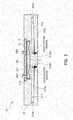
- a plurality of recessed housing portions 311 for housing the induction coils 4 are provided in the upper surface thereof horizontally and vertically symmetrically to the center in a plan view, as shown in FIG. 2 .
- the present embodiment illustrates the case where one recessed housing portion 311 is formed in a central portion of the metal plate body 31, and four recessed housing portions 311 are formed therearound equidistantly in the circumferential direction.
- Each recessed housing portion 311 is generally circular in a plan view, and the depth thereof is greater than or equal to the thickness of the induction coils 4, as shown in FIG. 3 .
- the recessed housing portion 311 is not limited to being generally circular in a plan view, and may be formed in various shapes in a plan view, such as elliptical, polygonal or rod-like.
- the induction coils 4 housed in the recessed housing portions 311 of the upper plate 3T are formed by winding a band-like coil to be generally ring-shaped, and the outline shape thereof in a plan view is generally the same as the shape of the opening of the recessed housing portions 311, as shown in FIG. 5 .
- recessed housing portions 311 for housing the induction coils 4 are provided in the lower surface thereof horizontally and vertically symmetrically to the center in a plan view, as shown in FIG. 2 , similarly to the upper plate 3T.
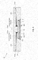
- Each recessed housing portion 311 is generally circular in a plan view, and the depth thereof is greater than or equal to the thickness of the induction coils 4 (see FIG. 4 ), similarly to the recessed housing portions 311 formed in the upper plate 3T.
- the configuration of the induction coils 4 that are housed in the recessed housing portions 311 of the lower plate 3D is similar to the induction coils 4 that are housed in the recessed housing portion 311 of the upper plate 3T described above.
- a cover placement portion 312 having a step greater than or equal to the thickness of the metal cover 32 is formed around the entire edge of the opening of the recessed housing portion 311.
- the tabular cover 32 is screwed fixed to this cover placement portion 312. Note that, after having been screwed fixed, the abutting surfaces of the cover 32 and the cover placement portion 312 are in close contact.
- the cover 32 that closes the recessed housing portions 311 of the upper plate 3T and the lower plate 3D is a discoid having approximately the same shape in a plan view as the opening of the cover placement portion 312 formed in the recessed housing portion 311, and, in the present embodiment, is a metal plate that is generally discoid in a plan view.
- an approximately straight slit portion 321 is formed in the cover 32 outwardly from the center in a diameter direction. This slit portion 321 enables induced current that is produced in the cover 32 to be suppressed, and heating of the actual cover 32 to be suppressed.
- lead-out holes 32H are formed in the cover 32 in order to lead output terminals 41 that extend from the induction coil 4 housed in the recessed housing portion 311 to the outside (see FIG. 6 ).
- This cover 32 is fixed such that the upper surface of the cover placement portion 312 and the inner surface of the cover 32 are in close contact with each other, by fixing screws that are not shown. Note that (the outer lateral surface of) the cover 32 fixed to the cover placement portion 312 is located inwardly with respect to the surface of the upper plate 3T and the lower plate 3D in which the cover placement portion 312 is formed (see FIG. 3 and FIG. 4 ).
- the outer lateral surface of the cover 32 is located inwardly with respect to the upper surface of the metal plate body 31 in the case of the upper plate 3T, and the outer lateral surface of the cover 32 is located inwardly with respect to the lower surface of the metal plate body 31 in the case of the lower plate 3D. External mechanisms and components of the plates 3T and 3D thereby do not need to be modified.
- a magnetic iron core 5 that has undergone division or slit machining is provided in the hollow portion of the induction coils 4 housed in the recessed housing portions 311 of the upper plate 3T and the lower plate 3D, as is shown in FIG. 3 and FIG. 4 .
- a magnetic circuit having low magnetic reluctance is formed within the hollow portion of the induction coils 4.
- the magnetic iron core 5 of the present embodiment is cylindrically formed by stacking a plurality of magnetic steel plates so as to be shifted in the width direction.
- the magnetic steel plates have a rectangular plate shape, and include a curved portion having a curved cross-section in the width direction.
- These magnetic steel plates are formed using silicon steel sheets having an insulating membrane applied to the surface thereof, for example, and have a plate thickness of approximately 0.3 mm, for example.
- the curved portion conceivably curves at a constant curvature along an entirety thereof or curves at a continuously changing curvature, and conceivably has an involute shape that uses a portion of an involute curve, a partial arc shape, or a partial elliptical shape, for example.
- insulation processing is performed on both the upper and lower ends of the magnetic iron core 5 or an insulating material is provided on both the upper and lower ends of the magnetic iron core 5. The occurrence of a short-circuit current that flows to both the upper and lower ends of the magnetic iron core 5 can thereby be prevented.
- a short circuit part 6 for conducting electricity that is made of a nonmagnetic metal such as copper or stainless steel, for example, is provided on the inner surface of the recessed housing portion 311, that is, specifically, on the bottom surface and the inner peripheral surface of the recessed housing portion 311, as shown in FIG. 3 and FIG. 4 .
- This short circuit part 6 for conducting electricity is formed using a copper sheet member, for example, and has a generally ring-shaped portion provided on the bottom surface of the recessed housing portion 311 to face the induction coil 4 and a generally cylindrical portion provided on the inner peripheral surface of the recessed housing portion 311 to face the outer peripheral surface of the induction coil 4.
- the short circuit part 6 for conducting electricity may be configured by one of the generally ring-shaped portion and the generally cylindrical portion.
- the jacket chambers 313 are formed in the metal plate body 31 of the upper plate 3T to be closer to the lower surface side than is the recessed housing portion 311, as shown in FIG. 3 , and are formed in the metal plate body 31 of the lower plate 3D to be closer to the upper surface side than is the recessed housing portion 311, as shown in FIG. 4 .
- the communication passage 314 of the present embodiment has a first communication passage 314m that communicates between inner end portions of adjacent jacket chambers 313, and a second communication passage 314n that communicates between outer end portions of adjacent jacket chambers 313.
- the lower surface of a coil adjacent portion that is adjacent to the induction coil 4 has a portion that is lower than the lower surface of portions other than the coil adjacent portion, and the jacket chambers 313 have a sloping surface 313x that slopes such that the liquid heating medium flows to the induction coil 4 side in the metal plate body 31, that is, to a coil disposition portion of the metal plate body 31, as shown in FIG. 3 and FIG. 4 .
- the plurality of jacket chambers 313 have a sloping surface 313x that slopes such that the liquid heating medium flows to the side of the induction coil 4 provided in the recessed housing portion 311 that is in a central portion of the metal plate body 31. More specifically, the lower surface of each jacket chamber 313 has a sloping surface 313x that slopes down toward the side of the induction coil provided in the recessed housing portion 311 that is in a central portion of the metal plate body 31.
- the sloping surface 313x shown in FIG. 3 and FIG. 4 is configured such that the lower surface of the jacket chamber 313 serves as the sloping surface 313x by forming the actual jacket chamber 313 to slope inside the metal plate body 31.
- the liquid heating medium on the induction coil 4 side thus vaporizes and flows outside the jacket chamber 313 and into the second communication passage 314n to transmit heat to the outer side of the metal plate body 31.
- the heating medium liquefied by transmitting heat to the metal plate body 31 again flows along the sloping surface 313x to the induction coil 4 side.
- jacket chamber 313 may also have the configuration of a second embodiment which will be discussed later (a configuration having a deep bottom 313p and a shallow bottom 313q discussed later).
- the mold induction heating device 100 With the mold induction heating device 100 according to the first embodiment constituted as described above, by housing the induction coils 4 in the recessed housing portions 311, magnetic flux that is produced by the induction coils 4 can be efficiently passed into the plates 3T and 3D, enabling the plates 3T and 3D to be efficiently induction heated.
- the mold 2 can then be efficiently heated, given that the plates 3T and 3D contact the upper end face 2a and the lower end face 2b of the mold 2.
- the temperature of the plates 3T and 3D can be equalized, enabling the mold 2 to be uniformly heated as a result.
- the jacket chambers 313 have a sloping surface 313x that slopes such that the liquid heating medium flows to the induction coil 4 side, gas-liquid circulation of the heating medium inside the jacket chambers 313 is promoted, enabling the temperature to be more readily equalized.
- the recessed housing portions 311 are closed and secured by the cover 32, leakage of magnetic flux outside the plates 3T and 3D can be further reduced without adversely affecting the pressure resistance of the plates 3T and 3D, enabling the heating efficiency and power factor to be improved.
- the induction coil 4 can be separated from the outside, enabling the prevention of corrosion of the induction coil 4 by corrosive gases that can exist outside.
- the cover placement portion 312 has a step that is greater than or equal to the thickness of the cover 32, components, mechanisms and the like that are disposed on the outside of the plates 3T and 3D do not need to be designed differently.
- the mold induction heating device 100 is used as a tire vulcanization molding device that houses a tire serving as a heating object in a mold 2 consisting of a pair of an upper mold and a lower mold, and heats and pressure molds the tire.
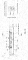
- this device is for induction heating the tire vulcanization mold 2, which has a generally columnar shape and forms a hollow portion 2X for housing a tire therein, as shown in FIG. 7 , and includes an upper plate 3T that is generally ring-shaped and contacts an upper end face 2a of the mold 2, a lower plate 3D that is generally ring-shaped and contacts a lower end face 2b of the mold 2, a side plate 3S that contacts an outer peripheral surface 2c of the mold 2, and an induction coil 4 that is provided for each of the plates 3T, 3D and 3S, and induction heats the plates 3T, 3D and 3S by supplying magnetic flux thereto when a voltage is applied by a 50 Hz or 60 Hz commercial power supply (not shown).
- an upper mold 21 of the mold 2 is fixed to the upper plate 3T
- a lower mold 22 of the mold 2 is fixed to the lower plate 3D
- a lateral mold 23 is fixed to a pressure piece 3S1 that is slidably attached to the side plate 3S.
- the mold 2 is configured such that, as a result of at least the upper plate 3T being raised or lowered by a lift mechanism 11, the upper mold 21 moves up and down relative to the lower mold 22, and the lateral mold 23 fixed to the pressure piece 3S1 moves in and out via a sloping surface 3Sa of the pressure piece 3S1.
- the lateral mold 23 is divided into a plurality of portions (e.g., 9 equal portions) in the circumferential direction, with these portions being disposed generally cylindrically, and the pressure piece 3S1 is provided in correspondence with each portion. Also, the pressure piece 3S1 is integrally formed with the lateral mold 23, and constitutes the lateral mold. At this time, the sloping surface 3Sa of the pressure piece 3S1 is the outer peripheral surface 2c of the lateral mold 23.
- the upper plate 3T has a generally discoid shape with an opening formed in a central portion thereof, and fixing slits S are formed inwardly from the outer periphery, as shown particularly in FIG. 8 . Note that the lift mechanism 11 is connected to the opening (see FIG. 7 ).
- the lower plate 3D similarly to the upper plate 3T, has a generally discoid shape with an opening formed in a central portion thereof, and fixing slits S are formed inwardly from the outer periphery, as shown in FIG. 9 .
- a supporting mechanism or the like for supporting the lower plate 3D is attached to the opening, for example.
- the side plate 3S as shown in FIG. 7 , has a generally cylindrical shape, and the slidable pressure piece 3S1 is provided on the inner surface thereof in the present embodiment.
- the upper plate 3T, the lower plate 3D and the side plate 3S each have a generally ring-shaped metal plate body 31 in which a recessed housing portion 311 that houses the induction coil 4 is formed, and a metal cover 32 that closes the recessed housing portion 311 with the induction coil 4 housed therein, and forms a closed magnetic circuit.
- a plurality of recessed housing portions 311 for housing the induction coils 4 are provided in the upper surface thereof in a horizontally and vertically symmetrical arrangement to the center in a plan view, as shown in FIG. 8 .
- Each recessed housing portion 311 is generally circular in a plan view, and the depth thereof is greater than or equal to the thickness of the induction coils 4, as shown in FIG. 10 .
- the induction coils 4 housed in the recessed housing portions 311 of the upper plate 3T are formed by winding a band-like coil to be generally ring-shaped, and the outline shape thereof in a plan view is generally the same as the shape of the opening of the recessed housing portions 311, as shown in FIG. 12 .
- the recessed housing portions 311 are provided in positions that avoid the holes, grooves, fixing slits S and the like provided in the upper plate 3T in order to attach other members or the like, that is, in positions that do not interfere with the holes, grooves, fixing slits S and the like (see FIG. 8 ).
- the recessed housing portion 311 is not limited to being generally circular in a plan view, and may be formed in various shapes in a plan view, such as elliptical, polygonal or rod-like.
- a plurality of recessed housing portions 311 for housing the induction coils 4 are provided in the lower surface thereof in a horizontally and vertically symmetrical arrangement to the center in a plan view, as shown in FIG. 9 .
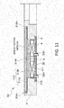
- Each recessed housing portion 311 is generally circular in a plan view, and the depth thereof is greater than or equal to the thickness of the induction coils 4, as shown in FIG. 11 , similarly to the recessed housing portions 311 formed in the upper plate 3T.
- the configuration of the induction coils 4 that are housed in the recessed housing portions 311 of the lower plate 3D is similar to the induction coils 4 that are housed in the recessed housing portion 311 of the upper plate 3T described above.
- the metal plate body 31 of the side plate 3S is provided such that the recessed housing portions 311, in which the induction coils 4 are housed by being wound around, extend around the outer peripheral surface thereof in the circumferential direction.
- the present embodiment two tiers (upper and lower) of recessed housing portions 311 are formed, but the present invention is not limited to two tiers, and there may be one or three or more tiers of recessed housing portions 311.
- a cover placement portion 312 having a step that is greater than or equal to the thickness of the metal cover 32 is formed around the entire edge of the opening of the recessed housing portion 311.
- the tabular metal cover 32 is screwed and fixed to this cover placement portion 312. Note that, after having been screwed and fixed, the abutting surfaces of the metal cover 32 and the cover placement portion 312 are in close contact.
- the side plate 3S is constituted such that the two tiers (upper and lower) of the recessed housing portions 311 are closed by a common metal cover 32, as shown in FIG. 7 .
- a cover placement portion 312 is formed in the top opening edge of the upper recessed housing portion 311, and a cover placement portion 312 is formed in the bottom opening edge of the lower recessed housing portion 311.
- the peripheral end face of a partition wall 31p that partitions the upper recessed housing portion 311 and the lower recessed housing portion 311 also serves as a cover placement portion 312.
- a curved metal cover 32 is screwed and fixed to this cover placement portion 312.
- the cover placement portion 312 is formed in correspondence with each tier, and each tier is closed by the metal cover 32.
- the metal cover 32 that closes the recessed housing portions 311 of the upper plate 3T and the lower plate 3D has a discoid shape that is approximately the same shape in a plan view as the opening of the cover placement portions 312 formed in the recessed housing portions 311, and, in the present embodiment, is a metal plate that is generally discoid in a plan view.
- an approximately straight slit portion 321 is formed in the metal cover 32 outwardly from the center in the diameter direction. This slit portion 321 enables an induced current that occurs in the metal cover 32 to be suppressed, and heating of the actual metal cover 32 to be suppressed.
- the metal cover 32 that closes the recessed housing portions 311 of the side plate 3S has a shape that fits into the cover placement portions 312 formed in the recessed housing portions 311, and, in the present embodiment, is a metal plate having a curved shape that curves with the same curvature as the cover placement portions 312. Also, this metal cover 32 is divided into a plurality of portions in the circumferential direction of the cover placement portions 312. By thus dividing the metal cover 32, induced current produced in the metal cover 32 can be suppressed, and the heating of the actual metal cover 32 can be suppressed.
- lead-out holes 32H are formed in the metal cover 32 in order to lead output terminals 41 that extend from the induction coils 4 housed in the recessed housing portions 311 to the outside (see FIG. 13 ).
- This metal cover 32 is fixed by fixing screws that are not illustrated, such that the upper surface of the cover placement portions 312 and the inner lateral surface of the metal cover 32 are in close contact. Note that (the outer lateral surface of) the metal cover 32 fixed to the cover placement portions 312 is located inwardly with respect to the surfaces of the upper plate 3T, the lower plate 3D and the side plate 3S in which the cover placement portions 312 are formed.
- the outer lateral surface of the metal cover 32 is located inwardly with respect to the upper surface of the metal plate body 31 in the case of the upper plate 3T, the outer lateral surface of the metal cover 32 is located inwardly with respect to the lower surface of the metal plate body 31 in the case of the lower plate 3D, and the outer lateral surface of the metal cover 32 is located inwardly with respect to the outer peripheral surface of the metal plate body 31 in the case of the side plate 3S.
- External mechanisms and components of the plates 3T, 3D and 3S thereby do not need to be modified.
- a magnetic iron core 5 that has undergone division or slit machining is provided in the hollow portion of the induction coils 4 housed in the recessed housing portions 311 of the upper plate 3T and the lower plate 3D, as is shown in FIG. 10 and FIG. 11 .
- a magnetic circuit having low magnetic reluctance is formed within the hollow portion of the induction coils 4.
- the magnetic iron core 5 of the present embodiment is cylindrically formed by stacking a plurality of magnetic steel plates to be shifted in the width direction.
- the magnetic steel plates have a rectangular plate shape, and include a curved portion having a curved cross-section in the width direction.
- These magnetic steel plates are formed using silicon steel sheets having an insulating membrane applied to the surface thereof, for example, and have a plate thickness of approximately 0.3 mm, for example.
- the curved portion conceivably curves at a constant curvature along an entirety thereof or curves at a continuously changing curvature, and conceivably has an involute shape that uses a portion of an involute curve, a partial arc shape, or a partial elliptical shape, for example.
- insulation processing is performed on both the upper and lower ends of the magnetic iron core 5 or an insulating material is provided on both the upper and lower ends of the magnetic iron core 5. The occurrence of a short-circuit current that flows to both the upper and lower ends of the magnetic iron core 5 can thereby be prevented.
- a short circuit part 6 for conducting electricity that is made of a nonmagnetic metal such as copper or stainless steel, for example, is provided on the inner surface of the recessed housing portion 311, that is, specifically, on the inner peripheral surface, as shown in FIG. 10 and FIG. 11 .
- This short circuit part 6 for conducting electricity is formed using a copper sheet member, for example, and is provided so as to cover approximately the entire inner peripheral surface of the recessed housing portion 311. Note that, while cross-sectional views of the upper plate 3T and the lower plate 3D are shown in FIG. 10 and FIG. 11 , a short circuit part 6 for conducting electricity may be provided on the inner surface of the recessed housing portions 311 of the side plate 3S.
- each plate a plurality of jacket chambers 313 in which a gas-liquid two phase heating medium is enclosed are formed, and a communication passage 314 that communicates between the jacket chambers 313 is further formed.
- the jacket chambers 313 are formed in the metal plate body 31 of the upper plate 3T to be closer to the lower surface side than is the recessed housing portion 311, and are formed in the metal plate body 31 of the lower plate 3D to be closer to the upper surface side than is the recessed housing portion 311, as shown in FIG. 7 . Also, the jacket chamber 313 is formed in the metal plate body 31 of the side plate 3S so as to be closer to the center side (inside surface side) than is the recessed housing portion 311.
- the jacket chamber 313 formed in the upper and lower plates 3D are provided so as to be substantially horizontally and vertically symmetrical to the center in a plan view, so as to avoid the fixing slit S formed in the upper and lower plates 3D.
- the communication passage 314 of the present embodiment has a first communication passage 314m that communicates between inner end portions of adjacent jacket chambers 313 in the diameter direction, and a second communication passage 314n that communicates between outer end portions of adjacent jacket chambers 313 in the diameter direction.
- the lower surface of a coil adjacent portion that is adjacent to the induction coil 4 has a portion that is lower than the lower surface of portions other than the coil adjacent portion, and the jacket chambers 313 have a deep bottom portion 313p formed such that the liquid heating medium collects on the induction coil 4 side, that is, in a coil disposition portion of the metal plate body 31, as shown in FIG. 10 and FIG. 11 .
- This deep bottom portion 313p is formed to span approximately the entirety of the coil adjacent portion that is adjacent to the induction coil 4 at the jacket chamber 313 (portion overlapping with the coil disposition portion of the metal plate body 31 in a plan view), and portions of the jacket chamber 313 other than the coil adjacent portion are shallow bottom portions 313q.
- the heating medium is enclosed in this jacket chamber 313 such that the liquid surface of the liquid heating medium is located not only in the deep bottom portion 313p, but also in the shallow bottom portion 313q.
- first communication passage 314m and the second communication passage 314n communicate between the shallow bottom portions 313q of the jacket chambers 313.
- the communication passage 314 has a third communication passage 314o that communicates between the deep bottom portions 313p of adjacent jacket chambers 313 (see FIGS. 8 to 11 ).
- the temperature of the upper plate 3T and the lower plate 3D in the diameter direction can be equalized. Also, because the jacket chambers 313 are in communication via the communication passage 314, the temperature of the upper plate 3T and the lower plate 3D in the circumferential direction can also be equalized. Furthermore, because the jacket chambers 313 are formed radially from the central portion of the upper plate 3T and the lower plate 3D, machining of the jacket chambers 313 can be facilitated.
- the liquid heating medium can be made to flow to the induction coil 4 side, and gas-liquid circulation of the heating medium inside the jacket chamber 313 is promoted, enabling the temperature to be more readily equalized.
- a commercial power supply having a commercial power supply frequency (50 Hz or 60 Hz) is used as the power supply for applying a voltage to the induction coils 4. Since a magnetic circuit having comparatively low magnetic reluctance is formed in the induction coil 4 by providing the induction coil 4 in the recessed housing portion 311, the characteristics of a high power factor of 70% to 90% are exhibited even in the case where a commercial power supply is used. Also, because a commercial power supply can be used, power supply costs can be kept down.
- the mold induction heating device 100 With the mold induction heating device 100 according to the second embodiment constituted as described above, by housing the induction coils 4 in the recessed housing portions 311, magnetic flux that is produced by the induction coils 4 can be efficiently passed into the plates 3T, 3D and 3S, enabling the plates 3T, 3D and 3S to be efficiently induction heated. Also, the generally columnar mold 2 can be efficiently heated, given that the plates 3T, 3D and 3S respectively contact the upper end face 2a, the lower end face 2b and the lateral face 2c of the mold 2.
- the temperature of the plates 3T, 3D and 3S can be equalized, enabling the mold 2 to be uniformly heated as a result. It thereby becomes possible to uniformly heat (vulcanize) tires, enabling high quality tires to be manufactured.
- the jacket chamber 313 has the deep bottom portion 313p in the coil adjacent portion, the liquid heating medium can be caused to flow to the induction coil 4 side, and gas-liquid circulation of the heating medium inside the jacket chambers 313 can be promoted, enabling the temperature to be more readily equalized.
- the recessed housing portions 311 are closed and secured by the metal cover 32, leakage of magnetic flux outside the plates 3T, 3D and 3S can be further reduced without adversely affecting the pressure resistance of the plates 3T, 3D and 3S, enabling the heating efficiency and power factor to be improved.
- the induction coil 4 can be separated from the outside, enabling the prevention of corrosion of the induction coil 4 by corrosive gases (e.g., sulfurous acid gas) that can exist outside.
- gases e.g., sulfurous acid gas
- cover placement portion 312 has a step that is greater than or equal to the thickness of the metal cover 32, components, mechanisms and the like that are disposed on the outside of the plates 3T, 3D and 3S do not need to be designed differently.
- a slit portion is formed in the metal cover that is fixed to the upper and lower plates
- the metal cover may be divided into a plurality of portions.
- the magnetic iron core of the above embodiments is cylindrically formed by stacking a plurality of magnetic steel plates to be shifted in the width direction
- an iron core or the like having a generally cylindrical shape and a slit portion formed in the lateral wall may alternatively be used.
- the recessed housing portion that is formed in the upper and lower plates may be generally ring-shaped.
- the recessed housing portions that are formed in the side plate are grooves that extend around in the circumferential direction, but may be recessed portions that are generally circular, similarly to the upper and lower plates.
- the recessed housing portion 311 As a mode for forming the recessed housing portion 311 to be generally circular, it is conceivable to form the recessed housing portion 311 more inwardly than the fixing slits S, concentrically surrounding the opening as shown in the plan view of FIG. 14 .
- the induction coil that is housed in this recessed housing portion 311 and the metal cover 32 have generally the same shape in a plan view as the opening of the recessed housing portion 311.
- a bottom view ( FIG. 15(A) ) and a right lateral view ( FIG. 15(B) ) of the heating plate (upper plate or lower plate) of FIG. 14 are shown.
- the jacket chamber 313 and communication passage 314 that are formed therein are shown with dotted lines.
- the induction coil 4 is desirably disposed in a portion that is less than or equal to half the size of the metal plate body 31 in the diameter direction from the position of the innermost ring of the metal plate body 31 in the diameter direction.
- the induction coil 4 is desirably disposed inwardly with respect to an intermediate position in the diameter direction between the position of the innermost ring of the metal plate body 31 in the diameter direction and the position of the outermost ring in the diameter direction.
- the temperature difference between high temperature portions and low temperature portions was 200 degrees or more.
- the induction coils 4 were disposed in portions that are less than or equal to half the size of the metal plate body 31 in the diameter direction from the position of the innermost ring of the metal plate body 31 in the diameter direction or a vicinity thereof, it was possible to reduce the temperature difference between the high temperature portions and low temperature portions to 10 degrees or less.
- the jacket chambers 313 formed in the upper plate 3T and the lower plate 3D are configured to have a deep bottom portion 313p and a shallow bottom portion 313q such that the lower surface of a coil adjacent portion that is adjacent to the induction coil 4 has a portion that is lower than the lower surface of portions other than the coil adjacent portion
- the jacket chambers 313 may have a sloping surface 313x that slopes such that the liquid heating medium flows to the induction coil side in the metal plate body 31, or in other words, to the coil disposition portion of the metal plate body 31.
- An enlarged cross-sectional view of the heating plate along the B-B line in FIG. 15 is shown in FIG. 16 . As shown in FIG.
- the jacket chamber 313 is formed so as to gradually slope toward the induction coil 4 side from the outer side of the metal plate body 31 in the diameter direction toward the inner side in the diameter direction.
- the jacket chamber 313 is formed at an incline so as to gradually slope away from the induction coil 4 from the outer side of the metal plate body 31 in the diameter direction to the inner side in the diameter direction.
- a fourth communication passage 314p may be provided that communicates between the plurality of jacket chambers 313, in the vicinity of the induction coils 4, as shown in FIG. 18 .
- Application of the present invention enables a mold to be efficiently and uniformly heated, and induction coils to be protected from corrosive gases.
Landscapes
- Physics & Mathematics (AREA)
- Electromagnetism (AREA)
- Engineering & Computer Science (AREA)
- Mechanical Engineering (AREA)
- Health & Medical Sciences (AREA)
- Toxicology (AREA)
- General Induction Heating (AREA)
- Moulds For Moulding Plastics Or The Like (AREA)
- Heating, Cooling, Or Curing Plastics Or The Like In General (AREA)
- Measuring Or Testing Involving Enzymes Or Micro-Organisms (AREA)
- Apparatus Associated With Microorganisms And Enzymes (AREA)
Claims (11)
- Forminduktionserwärmungsvorrichtung (100) zum induktiven Erwärmen einer Form (2), in der ein hohler Abschnitt (2X) gebildet ist, umfassend:eine obere Platte (3T), die eine obere Stirnfläche der Form (2) berührt;eine untere Platte (3D), die eine untere Stirnseite der Form (2) berührt; undeine Induktionsspule (4), die für jede Platte (3D, 3T) vorgesehen ist, und an die eine Spannung angelegt ist,wobei jede der Platten (3D, 3T) einen ringförmigen Metallplattenkörper (31), in dem ein zurückversetzter Aufnahmeabschnitt (311) zur Aufnahme der Induktionsspule (4) gebildet ist, und eine Metallabdeckung (32) hat, die den zurückversetzten Aufnahmeabschnitt (311) in einem Zustand, in dem die Induktionsspule (4) darin aufgenommen ist, verschließt,einen Abdeckungplatzierungsabschnitt (312), undeine Vielzahl von Mantelkammern (313) in den Metallplattenkörpern (31) gebildet ist, wobeidie Vielzahl von Mantelkammern (313) einen geschlossenen Bereich bildet, in dem ein Gas-Flüssigkeit-Zweiphasenheizmedium enthalten ist, und wobeidie Vielzahl von Mantelkammern (313) über eine Verbindungspassage (314) miteinander kommunizieren.
- Forminduktionserwärmungsvorrichtung nach Anspruch 1,
wobei eine untere Oberfläche eines Spulennachbarabschnitts, der mit der Induktionsspule (4) benachbart ist, in den Mantelkammern (313) einen Abschnitt hat, der niedriger als eine untere Oberfläche der Abschnitte, die nicht der Spulennachbarabschnitt sind, ist. - Forminduktionserwärmungsvorrichtung nach Anspruch 2,
wobei die Mantelkammern (313) mit einer Neigung in dem Metallplattenkörper (31) vorgesehen sind, sodass ein flüssiges Heizmedium zu der Induktionsspulenseite fließt. - Forminduktionserwärmungsvorrichtung nach Anspruch 1, wobei die Metallabdeckung (32), die jede der zurückversetzten Aufnahmeabschnitte (311) verschließt, in eine Vielzahl von Abschnitten geteilt ist oder einen Schlitzabschnitt (321) aufweist.
- Forminduktionserwärmungsvorrichtung nach Anspruch 1,
wobei der zurückversetzte Aufnahmeabschnitt (311), der in der oberen Platte (3T) oder der unteren Platte (3D) gebildet ist, in einer Draufsicht rund ist,
die Induktionsspule (4) im Allgemeinen ringförmig ist, und
ein magnetischer Eisenkern (5), der geteilt oder schlitzbearbeitet wurde, in einem Bereich vorgesehen ist, der in einem Zustand, in dem die Induktionsspule (4) in dem zurückversetzten Aufnahmeabschnitt (311) aufgenommen ist, in dem zurückversetzten Aufnahmeabschnitt (311) durch einen zentralen Abschnitt der Induktionsspule (4) gebildet ist. - Forminduktionserwärmungsvorrichtung nach Anspruch 1,
wobei der zurückversetzte Aufnahmeabschnitt (311), der in der oberen Platte (3T) oder der unteren Platte (3D) gebildet ist, in einer Draufsicht rund ist, und
die Induktionsspule (4) ringförmig ist und in einem Abschnitt angeordnet ist, der von einer Position eines innersten Rings des Metallplattenkörpers (31) in einer Querschnittsrichtung oder einer Nähe davon aus, geringer oder gleich der Hälfte einer Größe des Metallplattenkörpers (31) in der Querschnittsrichtung ist. - Forminduktionserwärmungsvorrichtung nach Anspruch 1,
wobei ein Kurzschlussteil (6) aus einem nichtmagnetischen Metall zum Leiten von Strom an einer inneren Oberfläche der zurückversetzten Aufnahmeabschnitt (311) vorgesehen ist. - Forminduktionserwärmungsvorrichtung nach Anspruch 1,
wobei die Mantelkammern (313) der oberen Platte (3T) und der unteren Platte (3D) von einem zentralen Abschnitt des Metallplattenkörpers (31) aus radial angeordnet sind. - Forminduktionserwärmungsvorrichtung nach Anspruch 1, wobei die Form (2) eine Form für Reifenvulkanisation ist.
- Forminduktionserwärmungsvorrichtung nach einem der Ansprüche 1 bis 9,
wobei der Abdeckungplatzierungsabschnitt (312) eine Stufe hat, die größer oder gleich einer Dicke der Metallabdeckung (32) ist, und der Abdeckungplatzierungsabschnitt (312) um einen gesamten Rand einer Öffnung des zurückversetzten Aufnahmeabschnitt (311) in dem Metallplattenkörper (31) gebildet ist. - Forminduktionserwärmungsvorrichtung nach einem der Ansprüche 1 bis 10,
wobei die Induktionsspule (4) geeignet ist, dass eine Spannung einer 50Hz oder 60Hz kommerziellen Stromversorgung an ihr angelegt wird.
Applications Claiming Priority (2)
| Application Number | Priority Date | Filing Date | Title |
|---|---|---|---|
| JP2012176415 | 2012-08-08 | ||
| PCT/JP2013/071212 WO2014024864A1 (ja) | 2012-08-08 | 2013-08-06 | 金型誘導加熱装置 |
Publications (3)
| Publication Number | Publication Date |
|---|---|
| EP2884819A1 EP2884819A1 (de) | 2015-06-17 |
| EP2884819A4 EP2884819A4 (de) | 2015-11-18 |
| EP2884819B1 true EP2884819B1 (de) | 2018-07-11 |
Family
ID=50068088
Family Applications (1)
| Application Number | Title | Priority Date | Filing Date |
|---|---|---|---|
| EP13828693.5A Not-in-force EP2884819B1 (de) | 2012-08-08 | 2013-08-06 | Induktionserwärmungsvorrichtung für eine gussform |
Country Status (5)
| Country | Link |
|---|---|
| US (1) | US9849610B2 (de) |
| EP (1) | EP2884819B1 (de) |
| JP (1) | JP6157471B2 (de) |
| CN (1) | CN104521321B (de) |
| WO (1) | WO2014024864A1 (de) |
Families Citing this family (5)
| Publication number | Priority date | Publication date | Assignee | Title |
|---|---|---|---|---|
| IT201600074867A1 (it) * | 2016-07-18 | 2018-01-18 | E Wenco S R L | Dispositivo di riscaldamento, uso e kit |
| CN108601128B (zh) * | 2018-04-19 | 2024-05-24 | 丰泽智能装备股份有限公司 | 电磁加热模具 |
| JP7491556B2 (ja) * | 2020-06-23 | 2024-05-28 | トクデン株式会社 | 伝熱プレート |
| DE102021121225A1 (de) | 2021-08-16 | 2023-02-16 | Deutsches Zentrum für Luft- und Raumfahrt e.V. | Presswerkzeug |
| PL131486U1 (pl) * | 2023-05-25 | 2024-12-02 | Explomet Gałka, Szulc Spółka Komandytowa | Stempel i matryca do obróbki materiałów warstwowych z wykorzystaniem pola indukcyjnego |
Family Cites Families (10)
| Publication number | Priority date | Publication date | Assignee | Title |
|---|---|---|---|---|
| GB890940A (en) | 1957-01-11 | 1962-03-07 | Beanwy Electric Ltd | Improvements in, or relating to, moulding-press and like platens |
| JPS61131388A (ja) * | 1984-11-29 | 1986-06-19 | トクデン株式会社 | 発熱金属平板 |
| JPS62225310A (ja) * | 1986-03-27 | 1987-10-03 | Yokohama Rubber Co Ltd:The | 加硫用金型 |
| JP3326406B2 (ja) | 1999-05-21 | 2002-09-24 | バンドー化学株式会社 | 円筒状金型の電磁誘導加熱方法と同電磁誘導加熱装置 |
| JP2001158020A (ja) * | 1999-12-06 | 2001-06-12 | Mitsubishi Heavy Ind Ltd | タイヤ加硫用割金型コンテナ |
| JP2004026575A (ja) | 2002-06-26 | 2004-01-29 | Matsushita Electric Ind Co Ltd | 成型装置 |
| JP4892724B2 (ja) | 2006-04-26 | 2012-03-07 | 国立大学法人東京工業大学 | 金型温度制御方法および金型温度制御装置 |
| EP2538748B1 (de) | 2010-02-19 | 2019-01-09 | Nippon Steel & Sumitomo Metal Corporation | Querfluss-induktionsheizvorrichtung |
| JP5582906B2 (ja) | 2010-07-27 | 2014-09-03 | 株式会社ブリヂストン | タイヤ用加硫モールドの加熱装置および加熱方法 |
| CN203542943U (zh) * | 2013-11-18 | 2014-04-16 | 三角(威海)华盛轮胎有限公司 | 轮胎硫化外模具电磁感应加热装置 |
-
2013
- 2013-08-06 CN CN201380041626.0A patent/CN104521321B/zh active Active
- 2013-08-06 JP JP2014529500A patent/JP6157471B2/ja active Active
- 2013-08-06 EP EP13828693.5A patent/EP2884819B1/de not_active Not-in-force
- 2013-08-06 WO PCT/JP2013/071212 patent/WO2014024864A1/ja not_active Ceased
- 2013-08-06 US US14/420,571 patent/US9849610B2/en active Active
Non-Patent Citations (1)
| Title |
|---|
| None * |
Also Published As
| Publication number | Publication date |
|---|---|
| US9849610B2 (en) | 2017-12-26 |
| EP2884819A1 (de) | 2015-06-17 |
| CN104521321B (zh) | 2016-06-22 |
| WO2014024864A1 (ja) | 2014-02-13 |
| JPWO2014024864A1 (ja) | 2016-07-25 |
| EP2884819A4 (de) | 2015-11-18 |
| CN104521321A (zh) | 2015-04-15 |
| JP6157471B2 (ja) | 2017-07-05 |
| US20150217484A1 (en) | 2015-08-06 |
Similar Documents
| Publication | Publication Date | Title |
|---|---|---|
| US8304940B2 (en) | Stator | |
| US9849610B2 (en) | Induction heating device for mold | |
| JPWO2016204238A1 (ja) | 電動機 | |
| JP5962570B2 (ja) | 回転電機 | |
| JP2016135049A (ja) | 密閉型回転電機 | |
| CN117999728A (zh) | 电机 | |
| WO2017082023A1 (ja) | 回転電機 | |
| US12068648B2 (en) | Motor | |
| JP2016154160A (ja) | 静止誘導電器 | |
| KR20160149594A (ko) | 변압기의 냉각장치 | |
| CN108573802A (zh) | 电抗器、电动机驱动装置、功率调节器以及机械 | |
| US20140139058A1 (en) | Stator structure | |
| JP2016035811A (ja) | 流体加熱装置 | |
| KR20120135503A (ko) | 고주파 스위치식 직류정류기의 변압기 모듈 구조 및 그 모듈 제조방법 | |
| EP2851912B1 (de) | Statisches elektrisches Induktionssystem | |
| KR20130076931A (ko) | 변압기 | |
| US10622138B2 (en) | Cooling ducts for transformers' winding | |
| TWI675384B (zh) | 靜態感應器 | |
| JP6152257B2 (ja) | 液冷モータ | |
| JP2013191623A (ja) | リアクトル | |
| KR20140005166U (ko) | 전력용 변압기 | |
| JP5566418B2 (ja) | 冷却器付き発熱装置 | |
| CN220527750U (zh) | 定子、电机及风力发电机组 | |
| JP5363221B2 (ja) | ステータ | |
| KR200412235Y1 (ko) | 지그-재그 방식의 권선 냉각구조 |
Legal Events
| Date | Code | Title | Description |
|---|---|---|---|
| PUAI | Public reference made under article 153(3) epc to a published international application that has entered the european phase |
Free format text: ORIGINAL CODE: 0009012 |
|
| 17P | Request for examination filed |
Effective date: 20150304 |
|
| AK | Designated contracting states |
Kind code of ref document: A1 Designated state(s): AL AT BE BG CH CY CZ DE DK EE ES FI FR GB GR HR HU IE IS IT LI LT LU LV MC MK MT NL NO PL PT RO RS SE SI SK SM TR |
|
| AX | Request for extension of the european patent |
Extension state: BA ME |
|
| DAX | Request for extension of the european patent (deleted) | ||
| RA4 | Supplementary search report drawn up and despatched (corrected) |
Effective date: 20151016 |
|
| RIC1 | Information provided on ipc code assigned before grant |
Ipc: B29C 33/02 20060101ALI20151012BHEP Ipc: H05B 6/04 20060101ALI20151012BHEP Ipc: H05B 6/10 20060101AFI20151012BHEP |
|
| GRAP | Despatch of communication of intention to grant a patent |
Free format text: ORIGINAL CODE: EPIDOSNIGR1 |
|
| STAA | Information on the status of an ep patent application or granted ep patent |
Free format text: STATUS: GRANT OF PATENT IS INTENDED |
|
| INTG | Intention to grant announced |
Effective date: 20180215 |
|
| GRAS | Grant fee paid |
Free format text: ORIGINAL CODE: EPIDOSNIGR3 |
|
| GRAA | (expected) grant |
Free format text: ORIGINAL CODE: 0009210 |
|
| STAA | Information on the status of an ep patent application or granted ep patent |
Free format text: STATUS: THE PATENT HAS BEEN GRANTED |
|
| AK | Designated contracting states |
Kind code of ref document: B1 Designated state(s): AL AT BE BG CH CY CZ DE DK EE ES FI FR GB GR HR HU IE IS IT LI LT LU LV MC MK MT NL NO PL PT RO RS SE SI SK SM TR |
|
| REG | Reference to a national code |
Ref country code: GB Ref legal event code: FG4D |
|
| REG | Reference to a national code |
Ref country code: CH Ref legal event code: EP |
|
| REG | Reference to a national code |
Ref country code: AT Ref legal event code: REF Ref document number: 1018309 Country of ref document: AT Kind code of ref document: T Effective date: 20180715 |
|
| REG | Reference to a national code |
Ref country code: IE Ref legal event code: FG4D |
|
| REG | Reference to a national code |
Ref country code: DE Ref legal event code: R096 Ref document number: 602013040225 Country of ref document: DE |
|
| REG | Reference to a national code |
Ref country code: FR Ref legal event code: PLFP Year of fee payment: 6 |
|
| REG | Reference to a national code |
Ref country code: NL Ref legal event code: MP Effective date: 20180711 |
|
| REG | Reference to a national code |
Ref country code: LT Ref legal event code: MG4D |
|
| REG | Reference to a national code |
Ref country code: AT Ref legal event code: MK05 Ref document number: 1018309 Country of ref document: AT Kind code of ref document: T Effective date: 20180711 |
|
| PG25 | Lapsed in a contracting state [announced via postgrant information from national office to epo] |
Ref country code: NL Free format text: LAPSE BECAUSE OF FAILURE TO SUBMIT A TRANSLATION OF THE DESCRIPTION OR TO PAY THE FEE WITHIN THE PRESCRIBED TIME-LIMIT Effective date: 20180711 |
|
| PG25 | Lapsed in a contracting state [announced via postgrant information from national office to epo] |
Ref country code: IS Free format text: LAPSE BECAUSE OF FAILURE TO SUBMIT A TRANSLATION OF THE DESCRIPTION OR TO PAY THE FEE WITHIN THE PRESCRIBED TIME-LIMIT Effective date: 20181111 Ref country code: RS Free format text: LAPSE BECAUSE OF FAILURE TO SUBMIT A TRANSLATION OF THE DESCRIPTION OR TO PAY THE FEE WITHIN THE PRESCRIBED TIME-LIMIT Effective date: 20180711 Ref country code: PL Free format text: LAPSE BECAUSE OF FAILURE TO SUBMIT A TRANSLATION OF THE DESCRIPTION OR TO PAY THE FEE WITHIN THE PRESCRIBED TIME-LIMIT Effective date: 20180711 Ref country code: SE Free format text: LAPSE BECAUSE OF FAILURE TO SUBMIT A TRANSLATION OF THE DESCRIPTION OR TO PAY THE FEE WITHIN THE PRESCRIBED TIME-LIMIT Effective date: 20180711 Ref country code: AT Free format text: LAPSE BECAUSE OF FAILURE TO SUBMIT A TRANSLATION OF THE DESCRIPTION OR TO PAY THE FEE WITHIN THE PRESCRIBED TIME-LIMIT Effective date: 20180711 Ref country code: BG Free format text: LAPSE BECAUSE OF FAILURE TO SUBMIT A TRANSLATION OF THE DESCRIPTION OR TO PAY THE FEE WITHIN THE PRESCRIBED TIME-LIMIT Effective date: 20181011 Ref country code: LT Free format text: LAPSE BECAUSE OF FAILURE TO SUBMIT A TRANSLATION OF THE DESCRIPTION OR TO PAY THE FEE WITHIN THE PRESCRIBED TIME-LIMIT Effective date: 20180711 Ref country code: NO Free format text: LAPSE BECAUSE OF FAILURE TO SUBMIT A TRANSLATION OF THE DESCRIPTION OR TO PAY THE FEE WITHIN THE PRESCRIBED TIME-LIMIT Effective date: 20181011 Ref country code: GR Free format text: LAPSE BECAUSE OF FAILURE TO SUBMIT A TRANSLATION OF THE DESCRIPTION OR TO PAY THE FEE WITHIN THE PRESCRIBED TIME-LIMIT Effective date: 20181012 Ref country code: FI Free format text: LAPSE BECAUSE OF FAILURE TO SUBMIT A TRANSLATION OF THE DESCRIPTION OR TO PAY THE FEE WITHIN THE PRESCRIBED TIME-LIMIT Effective date: 20180711 |
|
| PG25 | Lapsed in a contracting state [announced via postgrant information from national office to epo] |
Ref country code: HR Free format text: LAPSE BECAUSE OF FAILURE TO SUBMIT A TRANSLATION OF THE DESCRIPTION OR TO PAY THE FEE WITHIN THE PRESCRIBED TIME-LIMIT Effective date: 20180711 Ref country code: ES Free format text: LAPSE BECAUSE OF FAILURE TO SUBMIT A TRANSLATION OF THE DESCRIPTION OR TO PAY THE FEE WITHIN THE PRESCRIBED TIME-LIMIT Effective date: 20180711 Ref country code: AL Free format text: LAPSE BECAUSE OF FAILURE TO SUBMIT A TRANSLATION OF THE DESCRIPTION OR TO PAY THE FEE WITHIN THE PRESCRIBED TIME-LIMIT Effective date: 20180711 Ref country code: LV Free format text: LAPSE BECAUSE OF FAILURE TO SUBMIT A TRANSLATION OF THE DESCRIPTION OR TO PAY THE FEE WITHIN THE PRESCRIBED TIME-LIMIT Effective date: 20180711 |
|
| REG | Reference to a national code |
Ref country code: CH Ref legal event code: PL |
|
| REG | Reference to a national code |
Ref country code: DE Ref legal event code: R097 Ref document number: 602013040225 Country of ref document: DE |
|
| PG25 | Lapsed in a contracting state [announced via postgrant information from national office to epo] |
Ref country code: RO Free format text: LAPSE BECAUSE OF FAILURE TO SUBMIT A TRANSLATION OF THE DESCRIPTION OR TO PAY THE FEE WITHIN THE PRESCRIBED TIME-LIMIT Effective date: 20180711 Ref country code: IT Free format text: LAPSE BECAUSE OF FAILURE TO SUBMIT A TRANSLATION OF THE DESCRIPTION OR TO PAY THE FEE WITHIN THE PRESCRIBED TIME-LIMIT Effective date: 20180711 Ref country code: CZ Free format text: LAPSE BECAUSE OF FAILURE TO SUBMIT A TRANSLATION OF THE DESCRIPTION OR TO PAY THE FEE WITHIN THE PRESCRIBED TIME-LIMIT Effective date: 20180711 Ref country code: CH Free format text: LAPSE BECAUSE OF NON-PAYMENT OF DUE FEES Effective date: 20180831 Ref country code: EE Free format text: LAPSE BECAUSE OF FAILURE TO SUBMIT A TRANSLATION OF THE DESCRIPTION OR TO PAY THE FEE WITHIN THE PRESCRIBED TIME-LIMIT Effective date: 20180711 Ref country code: LU Free format text: LAPSE BECAUSE OF NON-PAYMENT OF DUE FEES Effective date: 20180806 Ref country code: MC Free format text: LAPSE BECAUSE OF FAILURE TO SUBMIT A TRANSLATION OF THE DESCRIPTION OR TO PAY THE FEE WITHIN THE PRESCRIBED TIME-LIMIT Effective date: 20180711 Ref country code: LI Free format text: LAPSE BECAUSE OF NON-PAYMENT OF DUE FEES Effective date: 20180831 |
|
| REG | Reference to a national code |
Ref country code: BE Ref legal event code: MM Effective date: 20180831 |
|
| PLBE | No opposition filed within time limit |
Free format text: ORIGINAL CODE: 0009261 |
|
| STAA | Information on the status of an ep patent application or granted ep patent |
Free format text: STATUS: NO OPPOSITION FILED WITHIN TIME LIMIT |
|
| REG | Reference to a national code |
Ref country code: IE Ref legal event code: MM4A |
|
| PG25 | Lapsed in a contracting state [announced via postgrant information from national office to epo] |
Ref country code: SM Free format text: LAPSE BECAUSE OF FAILURE TO SUBMIT A TRANSLATION OF THE DESCRIPTION OR TO PAY THE FEE WITHIN THE PRESCRIBED TIME-LIMIT Effective date: 20180711 Ref country code: SK Free format text: LAPSE BECAUSE OF FAILURE TO SUBMIT A TRANSLATION OF THE DESCRIPTION OR TO PAY THE FEE WITHIN THE PRESCRIBED TIME-LIMIT Effective date: 20180711 Ref country code: DK Free format text: LAPSE BECAUSE OF FAILURE TO SUBMIT A TRANSLATION OF THE DESCRIPTION OR TO PAY THE FEE WITHIN THE PRESCRIBED TIME-LIMIT Effective date: 20180711 |
|
| 26N | No opposition filed |
Effective date: 20190412 |
|
| GBPC | Gb: european patent ceased through non-payment of renewal fee |
Effective date: 20181011 |
|
| PG25 | Lapsed in a contracting state [announced via postgrant information from national office to epo] |
Ref country code: IE Free format text: LAPSE BECAUSE OF NON-PAYMENT OF DUE FEES Effective date: 20180806 |
|
| PG25 | Lapsed in a contracting state [announced via postgrant information from national office to epo] |
Ref country code: SI Free format text: LAPSE BECAUSE OF FAILURE TO SUBMIT A TRANSLATION OF THE DESCRIPTION OR TO PAY THE FEE WITHIN THE PRESCRIBED TIME-LIMIT Effective date: 20180711 Ref country code: BE Free format text: LAPSE BECAUSE OF NON-PAYMENT OF DUE FEES Effective date: 20180831 |
|
| PG25 | Lapsed in a contracting state [announced via postgrant information from national office to epo] |
Ref country code: GB Free format text: LAPSE BECAUSE OF NON-PAYMENT OF DUE FEES Effective date: 20181011 |
|
| PG25 | Lapsed in a contracting state [announced via postgrant information from national office to epo] |
Ref country code: MT Free format text: LAPSE BECAUSE OF NON-PAYMENT OF DUE FEES Effective date: 20180806 |
|
| PG25 | Lapsed in a contracting state [announced via postgrant information from national office to epo] |
Ref country code: TR Free format text: LAPSE BECAUSE OF FAILURE TO SUBMIT A TRANSLATION OF THE DESCRIPTION OR TO PAY THE FEE WITHIN THE PRESCRIBED TIME-LIMIT Effective date: 20180711 |
|
| PG25 | Lapsed in a contracting state [announced via postgrant information from national office to epo] |
Ref country code: PT Free format text: LAPSE BECAUSE OF FAILURE TO SUBMIT A TRANSLATION OF THE DESCRIPTION OR TO PAY THE FEE WITHIN THE PRESCRIBED TIME-LIMIT Effective date: 20180711 Ref country code: HU Free format text: LAPSE BECAUSE OF FAILURE TO SUBMIT A TRANSLATION OF THE DESCRIPTION OR TO PAY THE FEE WITHIN THE PRESCRIBED TIME-LIMIT; INVALID AB INITIO Effective date: 20130806 |
|
| PG25 | Lapsed in a contracting state [announced via postgrant information from national office to epo] |
Ref country code: MK Free format text: LAPSE BECAUSE OF NON-PAYMENT OF DUE FEES Effective date: 20180711 Ref country code: CY Free format text: LAPSE BECAUSE OF FAILURE TO SUBMIT A TRANSLATION OF THE DESCRIPTION OR TO PAY THE FEE WITHIN THE PRESCRIBED TIME-LIMIT Effective date: 20180711 |
|
| PGFP | Annual fee paid to national office [announced via postgrant information from national office to epo] |
Ref country code: FR Payment date: 20210823 Year of fee payment: 9 |
|
| PGFP | Annual fee paid to national office [announced via postgrant information from national office to epo] |
Ref country code: DE Payment date: 20210823 Year of fee payment: 9 |
|
| REG | Reference to a national code |
Ref country code: DE Ref legal event code: R119 Ref document number: 602013040225 Country of ref document: DE |
|
| PG25 | Lapsed in a contracting state [announced via postgrant information from national office to epo] |
Ref country code: FR Free format text: LAPSE BECAUSE OF NON-PAYMENT OF DUE FEES Effective date: 20220831 Ref country code: DE Free format text: LAPSE BECAUSE OF NON-PAYMENT OF DUE FEES Effective date: 20230301 |