EP2881271B1 - Vehicle air-conditioning apparatus - Google Patents
Vehicle air-conditioning apparatus Download PDFInfo
- Publication number
- EP2881271B1 EP2881271B1 EP14196932.9A EP14196932A EP2881271B1 EP 2881271 B1 EP2881271 B1 EP 2881271B1 EP 14196932 A EP14196932 A EP 14196932A EP 2881271 B1 EP2881271 B1 EP 2881271B1
- Authority
- EP
- European Patent Office
- Prior art keywords
- sliding
- type door
- air
- coupling shaft
- conditioning apparatus
- Prior art date
- Legal status (The legal status is an assumption and is not a legal conclusion. Google has not performed a legal analysis and makes no representation as to the accuracy of the status listed.)
- Not-in-force
Links
- 238000004378 air conditioning Methods 0.000 title claims description 70
- 230000008878 coupling Effects 0.000 claims description 157
- 238000010168 coupling process Methods 0.000 claims description 157
- 238000005859 coupling reaction Methods 0.000 claims description 157
- 238000010438 heat treatment Methods 0.000 claims description 39
- 238000011144 upstream manufacturing Methods 0.000 claims description 13
- 238000001816 cooling Methods 0.000 description 77
- 230000007246 mechanism Effects 0.000 description 66
- 238000009423 ventilation Methods 0.000 description 48
- 238000007664 blowing Methods 0.000 description 29
- 230000000694 effects Effects 0.000 description 4
- 230000009471 action Effects 0.000 description 3
- 238000005206 flow analysis Methods 0.000 description 3
- 238000004088 simulation Methods 0.000 description 3
- 230000008901 benefit Effects 0.000 description 2
- 230000001143 conditioned effect Effects 0.000 description 2
- 238000007710 freezing Methods 0.000 description 2
- 230000008014 freezing Effects 0.000 description 2
- 230000002093 peripheral effect Effects 0.000 description 2
- 239000011295 pitch Substances 0.000 description 2
- 239000000306 component Substances 0.000 description 1
- 239000012141 concentrate Substances 0.000 description 1
- 238000007791 dehumidification Methods 0.000 description 1
- 238000005516 engineering process Methods 0.000 description 1
- 238000009434 installation Methods 0.000 description 1
- 238000004519 manufacturing process Methods 0.000 description 1
- 239000000463 material Substances 0.000 description 1
- 239000002184 metal Substances 0.000 description 1
- 230000000452 restraining effect Effects 0.000 description 1
- 239000000126 substance Substances 0.000 description 1
- 230000002195 synergetic effect Effects 0.000 description 1
- 238000010257 thawing Methods 0.000 description 1
- 238000010792 warming Methods 0.000 description 1
Images


Classifications
-
- B—PERFORMING OPERATIONS; TRANSPORTING
- B60—VEHICLES IN GENERAL
- B60H—ARRANGEMENTS OF HEATING, COOLING, VENTILATING OR OTHER AIR-TREATING DEVICES SPECIALLY ADAPTED FOR PASSENGER OR GOODS SPACES OF VEHICLES
- B60H1/00—Heating, cooling or ventilating [HVAC] devices
- B60H1/00642—Control systems or circuits; Control members or indication devices for heating, cooling or ventilating devices
- B60H1/00664—Construction or arrangement of damper doors
- B60H1/00692—Damper doors moved by translation, e.g. curtain doors
-
- B—PERFORMING OPERATIONS; TRANSPORTING
- B60—VEHICLES IN GENERAL
- B60H—ARRANGEMENTS OF HEATING, COOLING, VENTILATING OR OTHER AIR-TREATING DEVICES SPECIALLY ADAPTED FOR PASSENGER OR GOODS SPACES OF VEHICLES
- B60H1/00—Heating, cooling or ventilating [HVAC] devices
- B60H1/00642—Control systems or circuits; Control members or indication devices for heating, cooling or ventilating devices
- B60H1/00814—Control systems or circuits characterised by their output, for controlling particular components of the heating, cooling or ventilating installation
- B60H1/00821—Control systems or circuits characterised by their output, for controlling particular components of the heating, cooling or ventilating installation the components being ventilating, air admitting or air distributing devices
- B60H1/00835—Damper doors, e.g. position control
- B60H1/00857—Damper doors, e.g. position control characterised by the means connecting the initiating means, e.g. control lever, to the damper door
Definitions
- the present invention relates to vehicle air-conditioning apparatus configured, for example, to open and close an air channel, and a vehicle air conditioning apparatus provided with the air channel opening-closing apparatus and, specifically, to a vehicle air conditioning apparatus provided with a sliding-type door mechanism.
- an air flow of air outside the vehicle or air inside the vehicle is supplied as an air flow having a flow velocity required by a blower fan.
- An interior of the air conditioning apparatus is provided with a flow channels for various air flows, and a cooling heat exchanger and heating heat exchanger are arranged therein.
- the supplied air flow is adjusted in wind velocity and air amount by being cooled, heated, or mixed in the interior of the apparatus, and is supplied from a blowing port for ventilation or a blowing port for defrosting, or a blowing port for feet into a vehicle cabin.
- the air flow to be supplied to the vehicle cabin is required to have adequate temperature, air amount, and wind velocity as a matter of course, and also to be comfortable up to the left side and right side of the blowing ports for ventilation or for feet, which are supply ports. Also, minimization of noise is also required.
- flow channels for various air flows are formed, and the air flow is regenerated as an air flow having required temperatures, air amount, and flow velocity while passing through the respective flow channels, and is guided to a blowing port into the vehicle cabin.
- a plurality of air flow channels are formed in the air conditioning apparatus and an opening-closing valve function for adjusting opening and closing of an opening is provided at a dividing port or a guiding branch of each of the air flow channel.
- the opening-closing valve function include a rotating valve and a sliding-type door mechanism, which are selected and used at suitable positions depending on applications.
- the sliding-type door mechanism is provided with a door sliding with respect to the air flow channel in the direction intersecting with a direction of air passage, occupies a small capacity in the interior of the vehicle air-conditioning apparatus, and thus contributes to achieve a compact profile of the air conditioning apparatus itself.
- the air passage channel switching apparatus disclosed in Patent Literature 1 and Patent Literature 2 are basically composed of a curved-shaped, or flat-shaped door and a rotational drive unit.
- the rotational drive unit is axially supported by a case, which is an outer frame in the vicinity of a bifurcating point of the air flow channel and includes a disc-shaped drive gear on a rotating shaft at a predetermined distance.
- the door is formed with a driven gear substantially on a power line extending along a sliding direction at a portion corresponding to the drive gear.
- the drive gear and the driven gear are engaged each other, and the rotation of the rotating shaft is transmitted to the drive gear. Accordingly, the door has a mechanism of making a sliding movement in a radial direction with respect to the rotating shaft.
- Air in the interior of the air conditioning apparatus is allowed to flow through a route passing through the cooling heat exchanger, then a heating heat exchanger to a mixing chamber, and a route passing through the cooling heat exchanger, then bypassing the heating heat exchanger to the mixing chamber.
- any of air-conditioning structures in the fully-cooling mode, the fully-hot mode, or the mixing mode it is needless to say that supplying a comfortable air flow having required temperature, wind velocity, and air amount to the vehicle cabin in a calm state without generation of noise is important for the air conditioning apparatus.
- employing a structure which eliminates an air ventilation resistance which impairs a smooth air flow and the air pressure thereof in any of the air flowing routes in the vehicle air-conditioning apparatus is a technical object, and substances or structures which impair air flow and generate an air ventilation resistance may cause generation of noise. Therefore, study and development for solving the problem are continued.
- Patent Literature 1 discloses a technical thought to prevent increases in air ventilation resistance and noise by focusing an attention on the shape of the rotational drive unit.
- the rotating shaft of the rotational drive unit is formed to have a flat cross section, and is set so that the longitudinal direction of the flat shape extends along the air flow in the fully-cooling mode and the fully-hot mode. Accordingly, the rotating shaft is capable of preventing increases in air ventilation resistance and noise without impairing the air flow.
- Fig. 12 illustrates the related art and is a schematic cross-sectional view of an arrangement of sliding-type door and a coupling shaft in the fully-cooling mode of the vehicle air-conditioning apparatus in the related art provided with a sliding-type door mechanism.
- the heating heat exchanger is arranged on the downstream side of the cooling heat exchanger, and the sliding-type door mechanism is arranged between these two heat exchangers.
- the sliding-type door mechanism includes a sliding-type door and a drive unit for driving the sliding-type door.
- the drive unit includes a plurality of substantially circular-shaped rotational drive units and a coupling shaft configured to couple the rotational drive units, and outer peripheries of the rotational drive units are configured as drive gears.
- the sliding-type door includes a driven gear, which is meshed with the drive gears.
- the drive unit is arranged on the upstream side of the sliding-type door, and interference with the heating heat exchanger is prevented.
- the sliding-type door is positioned at a lower end of a movable range. Accordingly, an opening (first flow-through opening) located above the sliding-type door is opened, and an opening (second flow-through opening) where the sliding-type door is positioned is closed. Air flowing out from the cooling heat exchanger passes through the first flow-through opening as a whole, and flows to respective blowing ports provided on the downstream side.
- Part of air flowing out from the cooling heat exchanger flows toward the sliding-type door and, simultaneously, changes the direction of flow upward in pursuit of an outflow port, and flows toward the first flow-through opening.
- the pressure of the air flow is low, and the wind velocity is low.
- the pressure is high and the wind velocity is also high (thick arrows in Fig. 12 ).
- the space in which the coupling shafts are arranged is a space in which the pressure is high and the wind velocity is also high in the fully-cooling mode.
- an eddy of air or the like is generated and causes an increase of an air ventilation resistance and increase of noise.
- Patent Literature 1 even though the air ventilation resistance can be reduced by devising the cross sections of the coupling shafts, since the coupling shafts are arranged in the space in which the pressure is high and the wind velocity is also high, an effect of retraining increases in air ventilation resistance and noise is limited.
- Patent Literature 2 discloses a technology of reducing an air ventilation resistance by forming an interior of the coupling shaft into a truss hollow structure and securing a channel of the air flow. Certain synergetic effects that the strength of a shaft structure is secured for transmitting a rotational drive force and simultaneously the air ventilation resistance with respect to an air flow is reduced are recognized in the truss hollow structure. However, the coupling shafts are still arranged in the space in which the pressure is high and the wind velocity is high, so that a fundamental problem resolution is not achieved.
- a vehicle air-conditioning apparatus provided with a sliding-type door mechanism according to the invention including: a case formed with a plurality of air channels in an interior thereof; a plate-shaped sliding-type door arranged so as to be slidable across the plurality of air channels in the case and configured to adjust the plurality of air channels to be opened and closed; a driven gear provided on the sliding-type door along a direction of movement of the sliding-type door and configured to move the sliding-type door in the direction of movement; a plurality of rotational drive units arranged across the direction of movement on an upstream side of the sliding-type door, at least one of the rotational drive units including a rotational drive gear configured to drive the sliding-type door by engaging the driven gear; and a coupling shaft configured to couple the plurality of rotational drive units at positions deviated from centers of rotation (Claim 1).
- the coupling shaft is at a position deviated from the centers of rotation of the rotational drive units, the position of the coupling shaft can be changed freely, and the coupling shaft may be moved away from a space in which a wind velocity and an air pressure are increased in a fully-cooling mode, a fully-hot mode, or a mixing mode thereof.
- the coupling shaft is set to be at a position most proximity to the sliding-type door when the sliding-type door is at a position substantially closing any one of the plurality of air channels (Claim 2).
- the sliding-type door includes a dig-in groove on a surface of the coupling shaft side along the length of the coupling shaft, and the coupling shaft is set at a position entering the dig-in groove of the sliding-type door when the sliding-type door is at a position of substantially closing any one of the plurality of air channels (Claim 3).
- the coupling shaft is set to be at a position farthest from the sliding-type door when the sliding-type door is at a position substantially closing any one of the plurality of air channels (Claim 4).
- the coupling shaft can be moved away from a position where the wind velocity and the air pressure are increased in the fully-cooling mode and the fully-hot mode, so that increases in air ventilation resistance and noise may be restrained.
- the coupling shaft is set to be at a position of the rotational drive unit where the wind velocity is lowest when the sliding type door is at the position substantially closing any one of the plurality of air channels (Claim 5).
- the coupling shaft can be arranged at a position where the wind velocity is low in the fully-cooling mode and the fully-hot mode, so that increases in air ventilation resistance and noise may be restrained.
- two of the coupling shafts are provided, one of the coupling shafts is set so as to take a position most proximity to the sliding-type door, and the other coupling shaft is arranged at a position farthest from the sliding-type door / or a position at which the wind velocity is lowest when the sliding-type door is at the position substantially closing one of the plurality of air channels (Claim 6).
- Rigidity of the rotational drive units may be increased while arranging the coupling shaft at a position in which increases in air ventilation resistance and noise are restrained in the fully-cooling mode and the fully-hot mode.
- the coupling shaft has a flat cross-sectional shape, and the coupling shaft is arranged so that the longitudinal direction of the flat shape extends along the direction of an air flow in the periphery of the coupling shaft when the sliding-type door is at the position substantially closing one of the plurality of air channels (Claim 7).
- the coupling shaft In the fully-cooling mode and the fully-hot mode, not only the coupling shaft is arranged at a position in which increases in air ventilation resistance and noise are restrained, the increases in air ventilation resistance and noise may be restrained further reliably.
- a heating heat exchanger to be arranged downstream of the sliding-type door is provided, and the plurality of air channels are applied to the vehicle air-conditioning apparatus in which the plurality of air channels are a warm channel that passes through the heat exchanger (12) and a bypass channel that bypasses the heat exchanger (12) (Claim 8), so that an effect of restraining increases in air ventilation resistance and noise is achieved.
- the vehicle air-conditioning apparatus including the sliding-type door mechanism configured to reliably prevent increases in air ventilation resistance and noise in the fully-cooling mode and the fully-hot mode is provided.
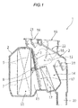
- Fig. 1 is a drawing for explaining a general configuration of a vehicle air-conditioning apparatus provided with a sliding-type door mechanism according to a first embodiment of the invention, and is a schematic drawing illustrating a cross section of a substantially center portion in a lateral direction of the vehicle air-conditioning apparatus. As illustrated in Fig.
- a vehicle air-conditioning apparatus 1 provided with the sliding-type door mechanism includes a case 2 provided with a plurality of air channels in an interior thereof, and includes a cooling heat exchanger 11, a sliding-type door 3, a rotational drive units 7, a coupling shaft 8, a driven gear 9, a heating heat exchanger 12, a defrost door 21, a ventilation door 22, and a foot door 23 arranged at predetermined positions in the case 2.
- the case 2 includes an air intake port (dotted portion on the left side in Fig. 1 ) configured to take air fed from a blower fan (not illustrated), and a blowing port for defrost 18, a blowing port for ventilation 19, and a foot blowing port 20 configured to blow out air conditioned in temperature.
- the air fed from the air intake port to the case 2 passes through the cooling heat exchanger 11, then passes through or bypasses the heating heat exchanger 12, reaches a mixing chamber 15, and then is blown out from blowing port for defrost 18, the the blowing port for ventilation 19, and a foot blowing port 20 in accordance with opening and closing the defrost door 21, the ventilation door 22, and the foot door 23.
- the cooling heat exchanger 11 is configured as part of a known freezing cycle (not illustrated), and is capable of cooling air by exchanging heat between air blown by a blower fan and a heat medium. It is also possible to configure that the heat exchange is not performed unless the freezing cycle is activated.
- the heating heat exchanger 12 is configured as part of a known heating cycle (not illustrated), and is capable of heating air by exchanging heat between air blown by the blower fan and a heat medium.
- the heating heat exchanger 12 is arranged on the downstream side of the cooling heat exchanger 11, and with this arrangement, a dehumidification heating operation is enabled by heating cold air dehumidified by the cooling heat exchanger 11.
- the heating heat exchanger 12 is arranged so as to cover part of the cooling heat exchanger 11 on the downstream side as illustrated in Fig. 1 . In this configuration, control of heating/not heating the air after having passed through the cooling heat exchanger 11 is enabled by changing the position of the sliding-type door 3 described later as needed.
- the heating heat exchanger 12 may be configured as an electric heat generating system instead of being configured as part of the heating cycle.
- the sliding-type door 3 is arranged between the cooling heat exchanger 11 and the heating heat exchanger 12, and is arranged so as to be slidable between a position for closing a front surface of the heating heat exchanger 12 and a position for closing a channel bypassing the heating heat exchanger 12.
- the sliding-type door 3 is provided with the driven gear 9 along a direction of movement of the sliding-type door as described later.
- Fig. 1 illustrates a state in which the sliding-type door 3 is slid to an upper end.
- the sliding-type door 3 opens a second flow-through opening 17 which allows air in a cold air channel 13 to flow toward the heating heat exchanger 12, and closes a first flow-through opening 16 which allows air in the cold air channel 13 to flow therethrough while bypassing the heating heat exchanger 12.
- a warm air channel 14 is provided on the downstream side of the heating heat exchanger 12, and becomes an air flow channel flowing out from the heating heat exchanger 12.
- the sliding-type door 3 when the sliding-type door 3 slides to a lower end (not illustrated), the sliding-type door 3 opens the first flow-through opening 16, and closes the second flow-through opening 17.
- the mixing chamber 15 is provided on the downstream of the first flow-through opening 16 and the warm air channel 14.
- a state in which the sliding-type door 3 is slid upward and closes the first flow-through opening 16 is referred to as "fully-hot mode".
- the air flow passing through the cold air channel 13 enters the mixing chamber 15 through the second flow-through opening 17, the heating heat exchanger 12, and the warm air channel 14.
- a state in which the sliding-type door 3 is slid downward and closes the second flow-through opening 17 is referred to as "fully-cooling mode".
- the air flow passing through the cold air channel 13 enters the mixing chamber 15 through the first flow-through opening 16.
- the air flow passing through the cold air channel 13 is bifurcated and flows into two flow channels.
- the air flow flows through a flow channel entering the mixing chamber 15 via the second flow-through opening 17, the heating heat exchanger 12, and the warm air channel 14, and a flow channel entering the mixing chamber 15 via the first flow-through opening 16.
- the two air flows are mixed in the mixing chamber 15, and flows to the blowing port for defrost 18, the blowing port for ventilation 19, or the foot blowing port 20.
- the blowing port for defrost 18 is provided with the defrost door 21
- the blowing port for ventilation 19 is provided with the ventilation door 22
- the foot blowing port 20 is provided with the foot door 23. Opening or closing states of the respective doors are determined by an operation from the vehicle cabin or by a known air conditioning automatic control apparatus and the amount of the air flow is adjusted thereby.
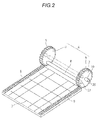
- Fig. 2 is a perspective view of the sliding-type door mechanism according to the first embodiment of the invention when viewed from the upstream of the air flow.
- the sliding-type door mechanism according to the embodiment includes the two rotational drive units 7, the coupling shaft 8, a drive unit 6 having two rotating shafts 10, and the sliding-type door 3.
- the two rotational drive units 7 are respectively joined to the coupling shaft 8, and on surfaces of the rotational drive units 7 opposite to surfaces to which the coupling shaft 8 is joined are provided with the rotating shafts 10 at a center thereof.
- the rotational drive units 7 each are provided with a drive gear 5 on an outer periphery thereof.
- the drive unit 6 is rotatable by the rotating shafts 10 being rotatably supported by the case 2 or the like.
- An axial direction of the coupling shaft 8 is set to be substantially parallel to an axial direction of the rotating shafts 10.
- the sliding-type door 3 is slidably supported by the case 2 or the like, and is provided with driven gears 9 on both sides thereof along a sliding direction.
- the drive gears 5 of the drive unit 6 and the driven gears 9 of the sliding-type door 3 engage each other, and are configured to slide the sliding-type door 3 to an arbitrary position by the rotating shafts 10 of the drive unit 6 rotated by an external motive power.
- Fig. 2 two of the circular-shaped rotational drive units 7 are illustrated. However, three or more of the rotational drive units 7 may be provided.
- the sliding-type door 3 are illustrated as having a flat plate shape. However, the sliding-type door 3 may be curved toward the coupling shaft 8 or away from the coupling shaft 8.
- the driven gears 9 may be formed integrally with the sliding-type door 3, or may be mounted after having formed as separate members.
- the sliding-type door mechanism according to the embodiment is characterized by the position where the substantially circular rotational drive units 7 and the coupling shaft 8 join.
- the coupling shaft 8 of the sliding-type door mechanism according to the embodiment is joined with the rotational drive units 7 at deviated positions (eccentric positions) 27 from centers of rotation 26 of the rotational drive units 7.
- the coupling shaft 8 is joined to the rotational drive units 7 on the outer peripheral side of the rotational drive units 7 with respect to positions where the centers of rotation 26 of the rotational drive units 7 are coupled illustrated by a dotted line in the same drawing.
- the coupling shaft 8 is capable of changing the distance from the sliding-type door 3 freely in accordance with the rotating action of the drive unit 6.
- a vehicle air-conditioning apparatus provided with a sliding-type door mechanism according to a second embodiment of the invention will be described.
- the coupling shaft 8 according to the embodiment is joined to the rotational drive units 7 at the eccentric positions 27 on the rotational drive units 7.
- the coupling shaft 8 is set at a position most proximity to the sliding-type door 3 in the fully-cooling mode and/or fully-hot mode.
- Fig. 3 is a schematic cross-sectional view of the vehicle air-conditioning apparatus provided with the sliding-type door mechanism according to the second embodiment of the invention, and a schematic cross-sectional view illustrating an arrangement of a sliding-type door and a coupling shaft and an air flow in a fully-cooling mode.
- the sliding-type door 3 illustrated in the same drawing makes a sliding movement so as to open the first flow-through opening 16 and close the second flow-through opening 17, and is positioned relatively downward of the drive unit 6.
- the coupling shaft 8 is at a position most proximity to the sliding-type door 3.
- the air flow passing through the cooling heat exchanger 11 is indicated by arrows (thin arrows and thick arrows) in Fig. 3 .
- air flowing out from the same height as the sliding-type door 3 flows toward the sliding-type door 3 and simultaneously, changes the direction of flow upward in pursuit of an outflow port, and flows toward the mixing chamber 15 via the first flow-through opening 16.
- the pressure of the air flow is low, and the wind velocity is low (thin arrows).
- the pressure is high and the wind velocity is also high (thick arrows).
- the coupling shaft 8 of this embodiment is at a position deviated from the centers of the rotational drive units 7 and most proximity to the sliding-type door 3. In this manner, since the coupling shaft 8 is not located in the space in which the pressure or the wind velocity of the air is increased, an increase in air ventilation resistance or an increase in noise caused by the sliding-type door mechanism may be restrained effectively.
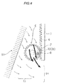
- Fig. 4 is a schematic cross-sectional view of a vehicle air-conditioning apparatus provided with a sliding-type door mechanism according to an embodiment of the invention, and a schematic cross-sectional view illustrating an arrangement of the sliding-type door and a coupling shaft and an air flow in a fully-hot mode.
- the sliding-type door 3 illustrated in the same drawing makes a sliding movement so as to close the first flow-through opening 16 and open the second flow-through opening 17, and is positioned relatively upward of the drive unit 6.
- the coupling shaft 8 is at a position most proximity to the sliding-type door 3.
- the air flow having passed through the cooling heat exchanger 11 is indicated by arrows (thin arrows and thick arrows) in Fig. 4 .
- Part of air passing through the cooling heat exchanger 11, which is flowing out from below the sliding-type door 3 flows straight toward the second flow-through opening 17 and then flows to the mixing chamber 15 via the heating heat exchanger 12, and the warm air channel 14.
- air flowing out from the same height as the sliding-type door 3 flows straight ahead toward the sliding-type door 3 and simultaneously, changes the direction of flow downward in pursuit of an outflow port, and flows toward the mixing chamber 15 via the second flow-through opening 17, the heating heat exchanger 12, and the warm air channel 14.
- the coupling shaft 8 of this embodiment is at the position deviated from the centers of the rotational drive units 7 and most proximity to the sliding-type door 3. In this manner, since the coupling shaft 8 is not located in the space in which the pressure or the wind velocity of the air is increased, an increase in air ventilation resistance or an increase in noise caused by the sliding-type door mechanism may be restrained effectively.
- a vehicle air-conditioning apparatus provided with a sliding-type door mechanism according to a third embodiment of the invention will be described.
- the coupling shaft 8 according to the embodiment is joined to the rotational drive units 7 at the eccentric positions 27 on the rotational drive units 7.
- the coupling shaft 8 is set at a position most proximity to the sliding-type door 3 in the fully-cooling mode and/or fully-hot mode.
- the coupling shaft 8 is set so as to be accommodated in a dig-in groove 24 formed on an upstream side surface of the sliding-type door 3.
- Fig. 5 is a schematic cross-sectional view of a vehicle air-conditioning apparatus provided with a sliding-type door mechanism according to a first example of the third embodiment of the invention, and a schematic cross-sectional view illustrating an arrangement of a sliding-type door and a coupling shaft and an air flow in the fully-cooling mode.
- the sliding-type door 3 illustrated in the same drawing makes a sliding movement so as to open the first flow-through opening 16 and close the second flow-through opening 17, and is positioned relatively downward of the drive unit 6.
- the sliding-type door 3 is provided with a dig-in groove 24 on the surface thereof on the upstream side surface of the air flow and an upper side along an axial direction of the coupling shaft 8.
- the air flow in the fully-cooling mode is the high in pressure and the high in wind velocity as well in a space where the direction of flow is changed as illustrated in Fig. 3 with thick arrows.
- the coupling shaft 8 in the third embodiment is accommodated within the dig-in groove 24 provided in the sliding-type door 3, the coupling shaft 8 is not exposed to the space where the air flows, so that increases in air ventilation resistance and noise caused by the sliding door mechanism may be effectively restrained.
- the sliding-type door mechanism according to the third embodiment is set so that the coupling shaft 8 is accommodated in the dig-in groove 24 formed on the upstream side surface of the sliding-type door 3 even in the fully-hot mode.
- the drawing illustrating the state of the fully-hot mode will be omitted.
- the sliding-type door 3 makes a sliding movement so as to close the first flow-through opening 16 and open the second flow-through opening 17 in the fully-hot mode, and is positioned relatively upward of the drive unit 6.
- the sliding-type door 3 is provided with the dig-in groove 24 on the upstream side surface of the air flow and a lower side along the axial direction of the coupling shaft 8.
- the air flow in the fully-hot mode is the high in pressure and the high in wind velocity as well in a space where the direction of flow is changed as illustrated in Fig. 4 with thick arrows.
- the coupling shaft 8 in the third embodiment is accommodated within the dig-in groove 24 provided in the sliding-type door 3, the coupling shaft 8 is not exposed to the space where the air flows, so that increases in air ventilation resistance and noise caused by the sliding door mechanism may be effectively restrained.
- Fig. 6 is an explanatory drawing of the sliding-type door mechanism according to the second example of the third embodiment of the invention, and is a perspective view of the sliding-type door mechanism for explaining a case where the coupling shaft 8 enters the dig-in groove 24 of the sliding-type door.
- Fig. 6 illustrates an upper portion of the door mechanism from the upstream side of the air flow.
- the dig-in groove 24 having a substantially semi-elliptical shape is formed on the upper side of the upstream side surface of the sliding-type door 3.
- another dig-in groove 24 is also formed on the lower side of the upstream side surface of the sliding-type door 3.
- the drive gear 5 installed on the side surface of the rotational drive unit 7 has a diameter slightly smaller than the diameter of the rotational drive unit 7.
- the coupling shaft 8 is joined with the rotational drive units 7 at deviated positions (eccentric positions) from the centers of rotation 26 of the rotational drive units 7 at the position of the outer periphery on the outside of the diameter of the drive gear 5.
- the coupling shaft 8 takes a position entering in the interior of the dig-in groove 24 formed on the upper surface of the sliding-type door 3 (accommodated in the dig-in groove 24).
- the coupling shaft 8 takes a position entering in the interior of the dig-in groove 24 formed on the lower surface of the sliding-type door 3 (accommodated in the dig-in groove 24).
- a vehicle air-conditioning apparatus provided with a sliding-type door mechanism according to a fourth embodiment of the invention will be described.
- the coupling shaft 8 according to the embodiment is joined to the rotational drive units 7 at the eccentric positions 27 on the rotational drive units 7.
- the coupling shaft 8 is set at a position farthest from the sliding-type door 3 in the fully-cooling mode and/or fully-hot mode.
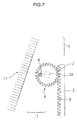
- Fig. 7 is a schematic cross-sectional view of the vehicle air-conditioning apparatus provided with the sliding-type door mechanism according to the fourth embodiment of the invention, and a schematic cross-sectional view illustrating an arrangement of a sliding-type door and a coupling shaft in the fully-cooling mode.
- the sliding-type door 3 illustrated in the same drawing makes a sliding movement so as to open the first flow-through opening 16 and close the second flow-through opening 17, and is positioned relatively downward of the drive unit 6.
- the coupling shaft 8 is at a position farthest from the sliding-type door 3.
- the air flow in the fully-cooling mode is the high in pressure and the high in wind velocity as well in a space where the direction of flow is changed as illustrated in Fig. 3 with thick arrows.
- the coupling shaft 8 of this embodiment is at a position deviated from the centers of the rotational drive units 7 and farthest from the sliding-type door 3. In this manner, since the coupling shaft 8 is not located in the space in which the pressure or the wind velocity of the air is increased, an increase in air ventilation resistance or an increase in noise caused by the sliding-type door mechanism may be restrained effectively.
- Fig. 8 is a schematic cross-sectional view of the vehicle air-conditioning apparatus provided with the sliding-type door mechanism according to the fourth embodiment of the invention, and a schematic cross-sectional view illustrating an arrangement of the sliding-type door and the coupling shaft in the fully-hot mode.
- the sliding-type door 3 illustrated in the same drawing makes a sliding movement so as to close the first flow-through opening 16 and open the second flow-through opening 17, and is positioned relatively upward of the drive unit 6.
- the coupling shaft 8 is at a position farthest from the sliding-type door 3.
- the air flow in the fully-hot mode is the high in pressure and the high in wind velocity as well in a space where the direction of flow is changed as illustrated in Fig. 4 with thick arrows.
- the coupling shaft 8 of this embodiment is at a position deviated from the centers of the rotational drive units 7 and farthest from the sliding-type door 3. In this manner, since the coupling shaft 8 is not located in the space in which the pressure or the wind velocity of the air is increased, an increase in air ventilation resistance or an increase in noise caused by the sliding-type door mechanism may be restrained effectively.
- a vehicle air-conditioning apparatus provided with a sliding-type door mechanism according to a fifth embodiment of the invention will be described.
- the coupling shaft 8 according to the embodiment is joined to the rotational drive units 7 at the eccentric positions 27 on the rotational drive units 7.
- the coupling shaft 8 is set at a position of the rotational drive units 7 where the wind velocity is lowest in the fully-cooling mode and/or fully-hot mode. An explanatory drawing is omitted.
- the vehicle air-conditioning apparatus is required to be reduced in size as described above, and a plurality of air flow channels are formed inside of a small case, and functional equipment such as the cooling heat exchanger and the heating heat exchanger, and the mechanisms such as the sliding-type door of the invention are arranged therein.
- the flow velocity and the air pressure of the air flow channel vary significantly depending on the structure of the air flow channel, the size, structure, shape, place of installation of the various functional equipment, or a general shape of the sliding-type door. Therefore, the position where the flow velocity of air and the air pressure become minimum in the fully-cooling mode and/or the fully-hot mode may not be a position farthest from the sliding-type door as has been described in the fourth embodiment.
- the flow velocity in the case of the vehicle air-conditioning apparatus may be estimated by an air flow analysis simulation.
- the position of the coupling shaft may be set by confirming the position where the flow velocity and the air pressure become minimum in the fully-cooling mode and/or the fully-hot mode by the air flow analysis simulation. For example, when the position where the flow velocity and the air pressure become minimum in the fully-cooling mode and/or the fully-hot mode is the position deviated from the position farthest from the sliding-type door, the drive gear and the driven gear may be set so that the coupling shaft is arranged at that deviated position.
- the drive unit 6 includes two coupling shafts 8 and 8 joined to the rotational drive units 7 at the eccentric positions 27.
- the two coupling shafts 8 and 8 are set so that one of the coupling shafts takes a position most proximity to the sliding-type door 3 and the other coupling shaft takes a position farthest from the sliding-type door 3 or a position where the wind velocity is the lowest in the fully-cooling mode and/or the fully-hot mode. A drawing is omitted.
- the drive unit 6 includes the two coupling shafts 8 and 8, and the respective coupling shafts 8 and 8 are joined to the rotational drive units 7 at positions substantially symmetrically deviated from the centers of rotation of the rotational drive unit 7. Therefore, the two coupling shafts 8 and 8 are increased in bearing force against the additional moment force and are capable of transmitting the applied rotational force efficiently.
- the two coupling shafts 8 and 8 are set so that one of the coupling shafts takes a position most proximity to the sliding-type door 3 and the other coupling shaft takes a position farthest from the sliding-type door 3 in the fully-cooling mode and/or the fully-hot mode. Therefore, since both of the two coupling shafts are not located in the space in which the pressure or the wind velocity of the air is increased as described in the second embodiment and the fourth embodiment described above, an increase in air ventilation resistance or an increase in noise caused by the sliding-type door mechanism may be restrained effectively.
- the coupling shafts set so as to take positions most proximity to the sliding-type door in the fully-cooling mode and/or the fully-hot mode may be set to positions entering the dig-in grooves on the sliding-type door, as described in the third embodiment.
- the coupling shafts set so as to take positions farthest from the sliding-type door in the fully-cooling mode and/or the fully-hot mode may be set to positions where the flow velocity of the air flow and the air pressure derived by the air flow analysis simulation becomes the minimum as described in the fifth embodiment.
- Both of the coupling shafts 8 are not located in the space in which the pressure or the wind velocity of the air is increased, an increase in air ventilation resistance or an increase in noise caused by the sliding-type door mechanism may be restrained effectively.
- a vehicle air-conditioning apparatus provided with a sliding-type door mechanism according to a seventh embodiment of the invention will be described.
- the driving unit 6 according to the seventh embodiment is joined to the rotational drive unit 7 at the eccentric positions 27 on the rotational drive unit 7.
- the coupling shaft 8 is set so as to be accommodated in the dig-in groove 24 formed on the upstream side surface of the sliding-type door 3.
- Fig. 9 is a schematic cross-sectional view of a vehicle air-conditioning apparatus provided with a sliding-type door mechanism according to a first example of the seventh embodiment, and a schematic cross-sectional view illustrating an arrangement of a sliding-type door and a coupling shaft in the fully-cooling mode.
- the sliding-type door 3 illustrated in the same drawing makes a sliding movement so as to open the first flow-through opening 16 and close the second flow-through opening 17, and is positioned relatively downward of the drive unit 6.
- the coupling shaft 8 is set to a state in which the longitudinal part of the substantially flat cross section extends along the air flow.
- the coupling shaft 8 is set so that the longitudinal direction of the substantially flat shape extends in the direction of the air flow in any of the case where the coupling shaft 8 is set at a position proximity to the sliding-type door 3, the case where the coupling shaft 8 is set at a position farthest from the sliding-type door 3, or the case where the coupling shaft 8 is set at a position where the wind velocity is the lowest.
- Fig. 11 is a schematic cross-sectional view of a vehicle air-conditioning apparatus provided with a sliding-type door mechanism according to a second example of the seventh embodiment, and a schematic cross-sectional view illustrating an arrangement of a sliding-type door and a coupling shaft in the fully-cooling mode;
- the coupling shaft 8 having a substantially flat shape in the fully-cooling mode enter (is accommodated in) the interior of the dig-in groove 24 formed on the surface on the upper side of the sliding-type door 3 is also applicable.
- the substantially flat shape of the coupling shaft 8 is similar to the shape of the dig-in groove 24 and has a structure in which the air ventilation resistance is minimized.
- the coupling shaft 8 is not located in the space in which the pressure or the wind velocity of the air is increased and, in addition, has substantially a flat shape which is set so that the longitudinal direction thereof extends along the direction of the air flow, an increase in air ventilation resistance or an increase in noise caused by the sliding-type door mechanism may be remarkably restrained effectively.
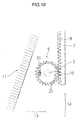
- Fig. 10 is a schematic cross-sectional view of the vehicle air-conditioning apparatus provided with the sliding-type door mechanism according to the first example of the seventh embodiment of the invention, and a schematic cross-sectional view illustrating an arrangement of the sliding-type door and the coupling shaft in the fully-hot mode.
- the sliding-type door 3 illustrated in the same drawing makes a sliding movement so as to close the first flow-through opening 16 and open the second flow-through opening 17, and is positioned relatively upward of the drive unit 6.
- the coupling shaft 8 is set so that the longitudinal direction of the substantially flat cross section extends along the air flow.
- the coupling shaft 8 is set so that the longitudinal direction of the substantially flat shape extends along the air flow in any of the case where the coupling shaft 8 is set at a position proximity to the sliding-type door 3, the case where the coupling shaft 8 is set at a position farthest from the sliding-type door 3, or the case where the coupling shaft 8 is set at a position where the wind velocity is the lowest.
- the two coupling shafts are set so that one of the coupling shafts takes a position most proximity to the sliding-type door and the other coupling shaft takes a position farthest from the sliding-type door or a position where the wind velocity is the lowest in the fully-cooling mode and/or the fully-hot mode as in the sixth embodiment
- a configuration in which the cross-sectional shape of the coupling shaft 8 is formed into a substantially flat shape and is set so that the longitudinal direction thereof extends along the air flow is also applicable.
- an increase in air ventilation resistance or an increase in noise caused by the sliding door mechanism may be significantly restrained effectively.
- the descriptions given thus far about the embodiments all relate to the structure and the mode of the sliding-type door mechanism in the fully-cooling mode and the fully-hot mode.
- the descriptions are about the sliding-type door of the invention as a function to adjust the opening and closing of the two air channels, namely the air channel extending from the cold air channel through the warm air channel to the mixing chamber and an air channel extending from the cold air channel directly to the mixing chamber.
- a number of air flow dividing ports such as the blowing port for defrost 18, the blowing port for ventilation 19, and the foot blowing port 20 are present in the internal structure of the vehicle air-conditioning apparatus.
- the type of adjustment of the air flow of the vehicle air conditioner includes various types of adjustments such as a wind direction adjustment, an air amount adjustment, an outside and inside air adjustment, in addition to a temperature adjustment and a humidity adjustment. Therefore, in order to achieve these various air flow adjustment, there is a case where the opening and closing adjustment is required in bifurcated opening portions of all of the air channels including the respective blowing ports.
- the sliding-type door 3 which is one of the embodiments of the invention is possible.
- the sliding-type door mechanism may be installed in an intersected manner so as to intersect the openings of the blowing port for defrost 18 and the blowing port for ventilation 19. It is needless to say that the respective structures and functions are the same as those in the first to the seventh embodiments described above.
- the sliding-type door of the vehicle air-conditioning apparatus provided with the sliding-type door mechanism of the invention is not limited to the function to adjust the opening and closing of the two air channels, namely the air channel extending from the cold air channel through the warm air channel to the mixing chamber and the air channel extending from the cold air channel directly to the mixing chamber.
- the sliding-type door of the vehicle air-conditioning apparatus provided with the sliding-type door mechanism of the invention may be applied as the sliding-type door for adjusting the opening ratio of the respective air flow channels at a number of air flow dividing ports provided in the interior of the air conditioning apparatus, and any of these modes are included within the technical scope of the invention.
- the shape of the sliding-type door of the vehicle air-conditioning apparatus provided with the sliding-type door of the embodiment of the invention has been illustrated in the drawing on the premise of a flat plate shape.
- the sliding-type door may be curved toward the coupling shaft, or away from the coupling shaft, and it is needless to say that the sliding-type door only needs to have a shape which can effectively close or open the plurality of air flow openings that divide the air flow into two directions.
- a vehicle air-conditioning apparatus which can prevent increases in air ventilation resistance and noise reliably is provided.
- the present invention has an influence on all of the materials, components, metal molds, and also a manufacturing industry relating to the vehicle air conditioning apparatus, and provides not only the automobile industry, but also general consumers widely with significant benefits. Industrial applicability of the invention is quite high.
Landscapes
- Physics & Mathematics (AREA)
- Thermal Sciences (AREA)
- Engineering & Computer Science (AREA)
- Mechanical Engineering (AREA)
- Air-Conditioning For Vehicles (AREA)
Applications Claiming Priority (1)
| Application Number | Priority Date | Filing Date | Title |
|---|---|---|---|
| JP2013253914A JP6256943B2 (ja) | 2013-12-09 | 2013-12-09 | 車両用空調装置 |
Publications (2)
| Publication Number | Publication Date |
|---|---|
| EP2881271A1 EP2881271A1 (en) | 2015-06-10 |
| EP2881271B1 true EP2881271B1 (en) | 2016-10-12 |
Family
ID=52102506
Family Applications (1)
| Application Number | Title | Priority Date | Filing Date |
|---|---|---|---|
| EP14196932.9A Not-in-force EP2881271B1 (en) | 2013-12-09 | 2014-12-09 | Vehicle air-conditioning apparatus |
Country Status (2)
| Country | Link |
|---|---|
| EP (1) | EP2881271B1 (enExample) |
| JP (1) | JP6256943B2 (enExample) |
Families Citing this family (6)
| Publication number | Priority date | Publication date | Assignee | Title |
|---|---|---|---|---|
| US10809021B2 (en) * | 2016-12-08 | 2020-10-20 | Hamilton Sunstrand Corporation | Heat exchanger with sliding aperture valve |
| CN106642934B (zh) * | 2016-12-15 | 2019-05-03 | 青岛海尔股份有限公司 | 挡风片保持架、分路送风装置及冰箱 |
| CN110435395A (zh) * | 2019-07-10 | 2019-11-12 | 浙江吉利控股集团有限公司 | 一种风门及具有该风门的空调 |
| DE102019219536A1 (de) * | 2019-12-13 | 2021-06-17 | Mahle International Gmbh | Belüftungsvorrichtung |
| CN112556145B (zh) * | 2020-12-29 | 2025-04-15 | 珠海格力电器股份有限公司 | 风口切换机构、风道结构和空调器 |
| CN112906138B (zh) * | 2021-03-31 | 2024-01-30 | 安徽江淮汽车集团股份有限公司 | 车门关闭空气阻力能量获取方法、装置、设备及存储介质 |
Family Cites Families (5)
| Publication number | Priority date | Publication date | Assignee | Title |
|---|---|---|---|---|
| JP3504806B2 (ja) * | 1996-04-24 | 2004-03-08 | 三菱重工業株式会社 | 車両用空気調和装置 |
| JP4132559B2 (ja) * | 1999-03-29 | 2008-08-13 | カルソニックカンセイ株式会社 | 車両用空気調和装置 |
| JP2004210034A (ja) | 2002-12-27 | 2004-07-29 | Zexel Valeo Climate Control Corp | スライドドア装置 |
| JP5287740B2 (ja) * | 2010-01-21 | 2013-09-11 | 株式会社デンソー | 空気通路開閉装置およびそれを備えた車両用空調装置 |
| JP5855448B2 (ja) * | 2011-12-26 | 2016-02-09 | カルソニックカンセイ株式会社 | ミックスドア構造 |
-
2013
- 2013-12-09 JP JP2013253914A patent/JP6256943B2/ja not_active Expired - Fee Related
-
2014
- 2014-12-09 EP EP14196932.9A patent/EP2881271B1/en not_active Not-in-force
Also Published As
| Publication number | Publication date |
|---|---|
| JP2015112890A (ja) | 2015-06-22 |
| JP6256943B2 (ja) | 2018-01-10 |
| EP2881271A1 (en) | 2015-06-10 |
Similar Documents
| Publication | Publication Date | Title |
|---|---|---|
| EP2881271B1 (en) | Vehicle air-conditioning apparatus | |
| CN105682951B (zh) | 车辆用空调装置 | |
| EP2357101B1 (en) | Sliding door device | |
| EP2559572A1 (en) | Air conditioner for vehicle | |
| JP2009113538A (ja) | 車両用空調装置 | |
| US20090215379A1 (en) | Vehicular air-conditioning system | |
| US20170217278A1 (en) | Air conditioning system for conditioning air in automobile passenger compartment | |
| JP6341114B2 (ja) | 車両用空調装置 | |
| CN106240289B (zh) | 用于机动车的空调系统的空气分配的装置 | |
| JP2015182760A (ja) | 車両用空調ユニット | |
| JP2010018248A (ja) | 車両用空調装置 | |
| KR101597905B1 (ko) | 자동차용 에어 컨디셔닝 시스템의 공기 디플렉터 장치 | |
| JP6269432B2 (ja) | 車両用空調装置 | |
| JP5287740B2 (ja) | 空気通路開閉装置およびそれを備えた車両用空調装置 | |
| WO2016158250A1 (ja) | 車両用空調ユニット | |
| JP5056057B2 (ja) | 車両用空調装置 | |
| KR101647253B1 (ko) | 자동차용 공기 조화 시스템의 공기 안내 장치 | |
| DE102006039286A1 (de) | Klimaanlage zur Fahrzeugnutzung | |
| JP2009006896A (ja) | 車両用空調装置 | |
| JP6372330B2 (ja) | 車両用空調ユニット | |
| WO2015151476A1 (ja) | ブロワユニット | |
| KR101714455B1 (ko) | 차량용 공조장치 | |
| JP5556757B2 (ja) | 車両用空調装置 | |
| KR101578104B1 (ko) | 차량용 공조장치 | |
| CN112297763A (zh) | 空调装置 |
Legal Events
| Date | Code | Title | Description |
|---|---|---|---|
| PUAI | Public reference made under article 153(3) epc to a published international application that has entered the european phase |
Free format text: ORIGINAL CODE: 0009012 |
|
| 17P | Request for examination filed |
Effective date: 20141209 |
|
| AK | Designated contracting states |
Kind code of ref document: A1 Designated state(s): AL AT BE BG CH CY CZ DE DK EE ES FI FR GB GR HR HU IE IS IT LI LT LU LV MC MK MT NL NO PL PT RO RS SE SI SK SM TR |
|
| AX | Request for extension of the european patent |
Extension state: BA ME |
|
| R17P | Request for examination filed (corrected) |
Effective date: 20151123 |
|
| RBV | Designated contracting states (corrected) |
Designated state(s): AL AT BE BG CH CY CZ DE DK EE ES FI FR GB GR HR HU IE IS IT LI LT LU LV MC MK MT NL NO PL PT RO RS SE SI SK SM TR |
|
| GRAP | Despatch of communication of intention to grant a patent |
Free format text: ORIGINAL CODE: EPIDOSNIGR1 |
|
| INTG | Intention to grant announced |
Effective date: 20160615 |
|
| GRAS | Grant fee paid |
Free format text: ORIGINAL CODE: EPIDOSNIGR3 |
|
| GRAA | (expected) grant |
Free format text: ORIGINAL CODE: 0009210 |
|
| AK | Designated contracting states |
Kind code of ref document: B1 Designated state(s): AL AT BE BG CH CY CZ DE DK EE ES FI FR GB GR HR HU IE IS IT LI LT LU LV MC MK MT NL NO PL PT RO RS SE SI SK SM TR |
|
| REG | Reference to a national code |
Ref country code: GB Ref legal event code: FG4D |
|
| REG | Reference to a national code |
Ref country code: CH Ref legal event code: EP |
|
| REG | Reference to a national code |
Ref country code: AT Ref legal event code: REF Ref document number: 836157 Country of ref document: AT Kind code of ref document: T Effective date: 20161015 |
|
| REG | Reference to a national code |
Ref country code: IE Ref legal event code: FG4D |
|
| REG | Reference to a national code |
Ref country code: DE Ref legal event code: R096 Ref document number: 602014004213 Country of ref document: DE |
|
| REG | Reference to a national code |
Ref country code: FR Ref legal event code: PLFP Year of fee payment: 3 |
|
| REG | Reference to a national code |
Ref country code: LT Ref legal event code: MG4D |
|
| REG | Reference to a national code |
Ref country code: NL Ref legal event code: MP Effective date: 20161012 |
|
| PG25 | Lapsed in a contracting state [announced via postgrant information from national office to epo] |
Ref country code: LV Free format text: LAPSE BECAUSE OF FAILURE TO SUBMIT A TRANSLATION OF THE DESCRIPTION OR TO PAY THE FEE WITHIN THE PRESCRIBED TIME-LIMIT Effective date: 20161012 |
|
| REG | Reference to a national code |
Ref country code: AT Ref legal event code: MK05 Ref document number: 836157 Country of ref document: AT Kind code of ref document: T Effective date: 20161012 |
|
| PG25 | Lapsed in a contracting state [announced via postgrant information from national office to epo] |
Ref country code: LT Free format text: LAPSE BECAUSE OF FAILURE TO SUBMIT A TRANSLATION OF THE DESCRIPTION OR TO PAY THE FEE WITHIN THE PRESCRIBED TIME-LIMIT Effective date: 20161012 Ref country code: NO Free format text: LAPSE BECAUSE OF FAILURE TO SUBMIT A TRANSLATION OF THE DESCRIPTION OR TO PAY THE FEE WITHIN THE PRESCRIBED TIME-LIMIT Effective date: 20170112 Ref country code: SE Free format text: LAPSE BECAUSE OF FAILURE TO SUBMIT A TRANSLATION OF THE DESCRIPTION OR TO PAY THE FEE WITHIN THE PRESCRIBED TIME-LIMIT Effective date: 20161012 Ref country code: GR Free format text: LAPSE BECAUSE OF FAILURE TO SUBMIT A TRANSLATION OF THE DESCRIPTION OR TO PAY THE FEE WITHIN THE PRESCRIBED TIME-LIMIT Effective date: 20170113 |
|
| PG25 | Lapsed in a contracting state [announced via postgrant information from national office to epo] |
Ref country code: PL Free format text: LAPSE BECAUSE OF FAILURE TO SUBMIT A TRANSLATION OF THE DESCRIPTION OR TO PAY THE FEE WITHIN THE PRESCRIBED TIME-LIMIT Effective date: 20161012 Ref country code: PT Free format text: LAPSE BECAUSE OF FAILURE TO SUBMIT A TRANSLATION OF THE DESCRIPTION OR TO PAY THE FEE WITHIN THE PRESCRIBED TIME-LIMIT Effective date: 20170213 Ref country code: BE Free format text: LAPSE BECAUSE OF FAILURE TO SUBMIT A TRANSLATION OF THE DESCRIPTION OR TO PAY THE FEE WITHIN THE PRESCRIBED TIME-LIMIT Effective date: 20161012 Ref country code: IS Free format text: LAPSE BECAUSE OF FAILURE TO SUBMIT A TRANSLATION OF THE DESCRIPTION OR TO PAY THE FEE WITHIN THE PRESCRIBED TIME-LIMIT Effective date: 20170212 Ref country code: AT Free format text: LAPSE BECAUSE OF FAILURE TO SUBMIT A TRANSLATION OF THE DESCRIPTION OR TO PAY THE FEE WITHIN THE PRESCRIBED TIME-LIMIT Effective date: 20161012 Ref country code: HR Free format text: LAPSE BECAUSE OF FAILURE TO SUBMIT A TRANSLATION OF THE DESCRIPTION OR TO PAY THE FEE WITHIN THE PRESCRIBED TIME-LIMIT Effective date: 20161012 Ref country code: ES Free format text: LAPSE BECAUSE OF FAILURE TO SUBMIT A TRANSLATION OF THE DESCRIPTION OR TO PAY THE FEE WITHIN THE PRESCRIBED TIME-LIMIT Effective date: 20161012 Ref country code: RS Free format text: LAPSE BECAUSE OF FAILURE TO SUBMIT A TRANSLATION OF THE DESCRIPTION OR TO PAY THE FEE WITHIN THE PRESCRIBED TIME-LIMIT Effective date: 20161012 Ref country code: FI Free format text: LAPSE BECAUSE OF FAILURE TO SUBMIT A TRANSLATION OF THE DESCRIPTION OR TO PAY THE FEE WITHIN THE PRESCRIBED TIME-LIMIT Effective date: 20161012 Ref country code: NL Free format text: LAPSE BECAUSE OF FAILURE TO SUBMIT A TRANSLATION OF THE DESCRIPTION OR TO PAY THE FEE WITHIN THE PRESCRIBED TIME-LIMIT Effective date: 20161012 |
|
| REG | Reference to a national code |
Ref country code: DE Ref legal event code: R097 Ref document number: 602014004213 Country of ref document: DE |
|
| PG25 | Lapsed in a contracting state [announced via postgrant information from national office to epo] |
Ref country code: SK Free format text: LAPSE BECAUSE OF FAILURE TO SUBMIT A TRANSLATION OF THE DESCRIPTION OR TO PAY THE FEE WITHIN THE PRESCRIBED TIME-LIMIT Effective date: 20161012 Ref country code: RO Free format text: LAPSE BECAUSE OF FAILURE TO SUBMIT A TRANSLATION OF THE DESCRIPTION OR TO PAY THE FEE WITHIN THE PRESCRIBED TIME-LIMIT Effective date: 20161012 Ref country code: CZ Free format text: LAPSE BECAUSE OF FAILURE TO SUBMIT A TRANSLATION OF THE DESCRIPTION OR TO PAY THE FEE WITHIN THE PRESCRIBED TIME-LIMIT Effective date: 20161012 Ref country code: EE Free format text: LAPSE BECAUSE OF FAILURE TO SUBMIT A TRANSLATION OF THE DESCRIPTION OR TO PAY THE FEE WITHIN THE PRESCRIBED TIME-LIMIT Effective date: 20161012 Ref country code: DK Free format text: LAPSE BECAUSE OF FAILURE TO SUBMIT A TRANSLATION OF THE DESCRIPTION OR TO PAY THE FEE WITHIN THE PRESCRIBED TIME-LIMIT Effective date: 20161012 |
|
| PLBE | No opposition filed within time limit |
Free format text: ORIGINAL CODE: 0009261 |
|
| STAA | Information on the status of an ep patent application or granted ep patent |
Free format text: STATUS: NO OPPOSITION FILED WITHIN TIME LIMIT |
|
| PG25 | Lapsed in a contracting state [announced via postgrant information from national office to epo] |
Ref country code: IT Free format text: LAPSE BECAUSE OF FAILURE TO SUBMIT A TRANSLATION OF THE DESCRIPTION OR TO PAY THE FEE WITHIN THE PRESCRIBED TIME-LIMIT Effective date: 20161012 Ref country code: BG Free format text: LAPSE BECAUSE OF FAILURE TO SUBMIT A TRANSLATION OF THE DESCRIPTION OR TO PAY THE FEE WITHIN THE PRESCRIBED TIME-LIMIT Effective date: 20170112 Ref country code: SM Free format text: LAPSE BECAUSE OF FAILURE TO SUBMIT A TRANSLATION OF THE DESCRIPTION OR TO PAY THE FEE WITHIN THE PRESCRIBED TIME-LIMIT Effective date: 20161012 |
|
| 26N | No opposition filed |
Effective date: 20170713 |
|
| PG25 | Lapsed in a contracting state [announced via postgrant information from national office to epo] |
Ref country code: MC Free format text: LAPSE BECAUSE OF FAILURE TO SUBMIT A TRANSLATION OF THE DESCRIPTION OR TO PAY THE FEE WITHIN THE PRESCRIBED TIME-LIMIT Effective date: 20161012 |
|
| REG | Reference to a national code |
Ref country code: IE Ref legal event code: MM4A |
|
| PG25 | Lapsed in a contracting state [announced via postgrant information from national office to epo] |
Ref country code: LU Free format text: LAPSE BECAUSE OF NON-PAYMENT OF DUE FEES Effective date: 20161209 |
|
| PG25 | Lapsed in a contracting state [announced via postgrant information from national office to epo] |
Ref country code: IE Free format text: LAPSE BECAUSE OF NON-PAYMENT OF DUE FEES Effective date: 20161209 Ref country code: SI Free format text: LAPSE BECAUSE OF FAILURE TO SUBMIT A TRANSLATION OF THE DESCRIPTION OR TO PAY THE FEE WITHIN THE PRESCRIBED TIME-LIMIT Effective date: 20161012 |
|
| REG | Reference to a national code |
Ref country code: FR Ref legal event code: PLFP Year of fee payment: 4 |
|
| PG25 | Lapsed in a contracting state [announced via postgrant information from national office to epo] |
Ref country code: HU Free format text: LAPSE BECAUSE OF FAILURE TO SUBMIT A TRANSLATION OF THE DESCRIPTION OR TO PAY THE FEE WITHIN THE PRESCRIBED TIME-LIMIT; INVALID AB INITIO Effective date: 20141209 |
|
| PG25 | Lapsed in a contracting state [announced via postgrant information from national office to epo] |
Ref country code: CY Free format text: LAPSE BECAUSE OF FAILURE TO SUBMIT A TRANSLATION OF THE DESCRIPTION OR TO PAY THE FEE WITHIN THE PRESCRIBED TIME-LIMIT Effective date: 20161012 Ref country code: MK Free format text: LAPSE BECAUSE OF FAILURE TO SUBMIT A TRANSLATION OF THE DESCRIPTION OR TO PAY THE FEE WITHIN THE PRESCRIBED TIME-LIMIT Effective date: 20161012 |
|
| REG | Reference to a national code |
Ref country code: CH Ref legal event code: PL |
|
| PG25 | Lapsed in a contracting state [announced via postgrant information from national office to epo] |
Ref country code: MT Free format text: LAPSE BECAUSE OF NON-PAYMENT OF DUE FEES Effective date: 20161209 |
|
| PG25 | Lapsed in a contracting state [announced via postgrant information from national office to epo] |
Ref country code: TR Free format text: LAPSE BECAUSE OF FAILURE TO SUBMIT A TRANSLATION OF THE DESCRIPTION OR TO PAY THE FEE WITHIN THE PRESCRIBED TIME-LIMIT Effective date: 20161012 |
|
| PG25 | Lapsed in a contracting state [announced via postgrant information from national office to epo] |
Ref country code: CH Free format text: LAPSE BECAUSE OF NON-PAYMENT OF DUE FEES Effective date: 20171231 Ref country code: LI Free format text: LAPSE BECAUSE OF NON-PAYMENT OF DUE FEES Effective date: 20171231 |
|
| GBPC | Gb: european patent ceased through non-payment of renewal fee |
Effective date: 20181209 |
|
| PG25 | Lapsed in a contracting state [announced via postgrant information from national office to epo] |
Ref country code: GB Free format text: LAPSE BECAUSE OF NON-PAYMENT OF DUE FEES Effective date: 20181209 |
|
| PGFP | Annual fee paid to national office [announced via postgrant information from national office to epo] |
Ref country code: FR Payment date: 20191231 Year of fee payment: 6 |
|
| PG25 | Lapsed in a contracting state [announced via postgrant information from national office to epo] |
Ref country code: AL Free format text: LAPSE BECAUSE OF FAILURE TO SUBMIT A TRANSLATION OF THE DESCRIPTION OR TO PAY THE FEE WITHIN THE PRESCRIBED TIME-LIMIT Effective date: 20161012 |
|
| PG25 | Lapsed in a contracting state [announced via postgrant information from national office to epo] |
Ref country code: FR Free format text: LAPSE BECAUSE OF NON-PAYMENT OF DUE FEES Effective date: 20201231 |
|
| PGFP | Annual fee paid to national office [announced via postgrant information from national office to epo] |
Ref country code: DE Payment date: 20211210 Year of fee payment: 8 |
|
| REG | Reference to a national code |
Ref country code: DE Ref legal event code: R119 Ref document number: 602014004213 Country of ref document: DE |
|
| PG25 | Lapsed in a contracting state [announced via postgrant information from national office to epo] |
Ref country code: DE Free format text: LAPSE BECAUSE OF NON-PAYMENT OF DUE FEES Effective date: 20230701 |