EP2881196B1 - Method for continuously casting steel - Google Patents
Method for continuously casting steel Download PDFInfo
- Publication number
- EP2881196B1 EP2881196B1 EP13825044.4A EP13825044A EP2881196B1 EP 2881196 B1 EP2881196 B1 EP 2881196B1 EP 13825044 A EP13825044 A EP 13825044A EP 2881196 B1 EP2881196 B1 EP 2881196B1
- Authority
- EP
- European Patent Office
- Prior art keywords
- slab
- casting
- bulging
- reduction
- zone
- Prior art date
- Legal status (The legal status is an assumption and is not a legal conclusion. Google has not performed a legal analysis and makes no representation as to the accuracy of the status listed.)
- Active
Links
- 238000005266 casting Methods 0.000 title claims description 168
- 229910000831 Steel Inorganic materials 0.000 title claims description 71
- 239000010959 steel Substances 0.000 title claims description 71
- 238000000034 method Methods 0.000 title claims description 36
- 230000009467 reduction Effects 0.000 claims description 168
- 238000007711 solidification Methods 0.000 claims description 65
- 230000008023 solidification Effects 0.000 claims description 65
- 230000006835 compression Effects 0.000 claims description 60
- 238000007906 compression Methods 0.000 claims description 60
- 239000007790 solid phase Substances 0.000 claims description 54
- 238000005096 rolling process Methods 0.000 claims description 33
- 238000001816 cooling Methods 0.000 claims description 20
- 238000009749 continuous casting Methods 0.000 claims description 18
- 230000003247 decreasing effect Effects 0.000 claims description 17
- 239000000498 cooling water Substances 0.000 claims description 10
- 230000009471 action Effects 0.000 claims description 4
- 238000005204 segregation Methods 0.000 description 120
- 238000012360 testing method Methods 0.000 description 34
- 239000011572 manganese Substances 0.000 description 24
- 229910052748 manganese Inorganic materials 0.000 description 21
- 230000000694 effects Effects 0.000 description 18
- PWHULOQIROXLJO-UHFFFAOYSA-N Manganese Chemical compound [Mn] PWHULOQIROXLJO-UHFFFAOYSA-N 0.000 description 17
- 239000000523 sample Substances 0.000 description 13
- 238000011144 upstream manufacturing Methods 0.000 description 11
- 239000007921 spray Substances 0.000 description 9
- 238000012546 transfer Methods 0.000 description 9
- 239000013078 crystal Substances 0.000 description 7
- 238000005452 bending Methods 0.000 description 6
- 229910052799 carbon Inorganic materials 0.000 description 6
- 238000005336 cracking Methods 0.000 description 6
- 229910052717 sulfur Inorganic materials 0.000 description 6
- 238000007654 immersion Methods 0.000 description 5
- OKTJSMMVPCPJKN-UHFFFAOYSA-N Carbon Chemical compound [C] OKTJSMMVPCPJKN-UHFFFAOYSA-N 0.000 description 4
- NINIDFKCEFEMDL-UHFFFAOYSA-N Sulfur Chemical compound [S] NINIDFKCEFEMDL-UHFFFAOYSA-N 0.000 description 4
- 238000005520 cutting process Methods 0.000 description 4
- PXHVJJICTQNCMI-UHFFFAOYSA-N nickel Substances [Ni] PXHVJJICTQNCMI-UHFFFAOYSA-N 0.000 description 4
- 229910052698 phosphorus Inorganic materials 0.000 description 4
- 239000011593 sulfur Substances 0.000 description 4
- XLYOFNOQVPJJNP-UHFFFAOYSA-N water Substances O XLYOFNOQVPJJNP-UHFFFAOYSA-N 0.000 description 4
- 229910052804 chromium Inorganic materials 0.000 description 3
- 239000011651 chromium Substances 0.000 description 3
- 239000007791 liquid phase Substances 0.000 description 3
- 229910052759 nickel Inorganic materials 0.000 description 3
- 229910052710 silicon Inorganic materials 0.000 description 3
- OAICVXFJPJFONN-UHFFFAOYSA-N Phosphorus Chemical compound [P] OAICVXFJPJFONN-UHFFFAOYSA-N 0.000 description 2
- 229910052782 aluminium Inorganic materials 0.000 description 2
- 238000013459 approach Methods 0.000 description 2
- 230000015572 biosynthetic process Effects 0.000 description 2
- 229910052802 copper Inorganic materials 0.000 description 2
- 238000009826 distribution Methods 0.000 description 2
- 230000007246 mechanism Effects 0.000 description 2
- 238000002844 melting Methods 0.000 description 2
- 230000008018 melting Effects 0.000 description 2
- 230000005499 meniscus Effects 0.000 description 2
- 229910052751 metal Inorganic materials 0.000 description 2
- 239000002184 metal Substances 0.000 description 2
- 238000013508 migration Methods 0.000 description 2
- 230000005012 migration Effects 0.000 description 2
- 239000003595 mist Substances 0.000 description 2
- 239000011574 phosphorus Substances 0.000 description 2
- 230000002265 prevention Effects 0.000 description 2
- 238000013441 quality evaluation Methods 0.000 description 2
- 238000005070 sampling Methods 0.000 description 2
- 238000005507 spraying Methods 0.000 description 2
- 230000008961 swelling Effects 0.000 description 2
- VYZAMTAEIAYCRO-UHFFFAOYSA-N Chromium Chemical compound [Cr] VYZAMTAEIAYCRO-UHFFFAOYSA-N 0.000 description 1
- UFHFLCQGNIYNRP-UHFFFAOYSA-N Hydrogen Chemical compound [H][H] UFHFLCQGNIYNRP-UHFFFAOYSA-N 0.000 description 1
- XUIMIQQOPSSXEZ-UHFFFAOYSA-N Silicon Chemical compound [Si] XUIMIQQOPSSXEZ-UHFFFAOYSA-N 0.000 description 1
- XAGFODPZIPBFFR-UHFFFAOYSA-N aluminium Chemical compound [Al] XAGFODPZIPBFFR-UHFFFAOYSA-N 0.000 description 1
- 230000005540 biological transmission Effects 0.000 description 1
- 230000008859 change Effects 0.000 description 1
- 230000000052 comparative effect Effects 0.000 description 1
- 239000000470 constituent Substances 0.000 description 1
- 230000007547 defect Effects 0.000 description 1
- 238000010586 diagram Methods 0.000 description 1
- 230000014509 gene expression Effects 0.000 description 1
- 229910052739 hydrogen Inorganic materials 0.000 description 1
- 239000001257 hydrogen Substances 0.000 description 1
- 230000014759 maintenance of location Effects 0.000 description 1
- 238000005192 partition Methods 0.000 description 1
- 230000000717 retained effect Effects 0.000 description 1
- 239000010703 silicon Substances 0.000 description 1
- 239000000126 substance Substances 0.000 description 1
- 238000003466 welding Methods 0.000 description 1
Images


Classifications
-
- B—PERFORMING OPERATIONS; TRANSPORTING
- B22—CASTING; POWDER METALLURGY
- B22D—CASTING OF METALS; CASTING OF OTHER SUBSTANCES BY THE SAME PROCESSES OR DEVICES
- B22D11/00—Continuous casting of metals, i.e. casting in indefinite lengths
- B22D11/12—Accessories for subsequent treating or working cast stock in situ
- B22D11/1206—Accessories for subsequent treating or working cast stock in situ for plastic shaping of strands
-
- B—PERFORMING OPERATIONS; TRANSPORTING
- B22—CASTING; POWDER METALLURGY
- B22D—CASTING OF METALS; CASTING OF OTHER SUBSTANCES BY THE SAME PROCESSES OR DEVICES
- B22D11/00—Continuous casting of metals, i.e. casting in indefinite lengths
- B22D11/04—Continuous casting of metals, i.e. casting in indefinite lengths into open-ended moulds
- B22D11/041—Continuous casting of metals, i.e. casting in indefinite lengths into open-ended moulds for vertical casting
-
- B—PERFORMING OPERATIONS; TRANSPORTING
- B22—CASTING; POWDER METALLURGY
- B22D—CASTING OF METALS; CASTING OF OTHER SUBSTANCES BY THE SAME PROCESSES OR DEVICES
- B22D11/00—Continuous casting of metals, i.e. casting in indefinite lengths
- B22D11/12—Accessories for subsequent treating or working cast stock in situ
- B22D11/128—Accessories for subsequent treating or working cast stock in situ for removing
- B22D11/1281—Vertical removing
-
- B—PERFORMING OPERATIONS; TRANSPORTING
- B22—CASTING; POWDER METALLURGY
- B22D—CASTING OF METALS; CASTING OF OTHER SUBSTANCES BY THE SAME PROCESSES OR DEVICES
- B22D11/00—Continuous casting of metals, i.e. casting in indefinite lengths
- B22D11/12—Accessories for subsequent treating or working cast stock in situ
- B22D11/128—Accessories for subsequent treating or working cast stock in situ for removing
- B22D11/1282—Vertical casting and curving the cast stock to the horizontal
-
- B—PERFORMING OPERATIONS; TRANSPORTING
- B22—CASTING; POWDER METALLURGY
- B22D—CASTING OF METALS; CASTING OF OTHER SUBSTANCES BY THE SAME PROCESSES OR DEVICES
- B22D11/00—Continuous casting of metals, i.e. casting in indefinite lengths
- B22D11/16—Controlling or regulating processes or operations
- B22D11/20—Controlling or regulating processes or operations for removing cast stock
- B22D11/208—Controlling or regulating processes or operations for removing cast stock for aligning the guide rolls
Definitions
- the present invention relates to a method for reducing the central segregation in slabs by intentionally bulging a slab drawn from a casting mold while avoiding the occurrence of a breakout and internal cracks, and thereafter compressing the slab being continuously cast that has an unsolidified layer.
- a molten steel is poured into a water-cooled casting mold and is cooled (this cooling is written as the "primary cooling") to form a solidified shell in contact with the inner wall of the casting mold.
- This slab having the solidified shell as the outer shell is continuously drawn in a downward direction while being supported by a large number of slab-supporting rolls disposed below the casting mold.
- the surface of the slab is cooled by, for example, spraying cooling water (this cooling is written as the "secondary cooling”) to solidify the slab thoroughly to the core.
- the slab is then cut into slabs having a prescribed length.
- Steel slabs manufactured in the above manner sometimes contain internal defects called central segregation in the core.
- This central segregation is ascribed to the enrichment of solute components such as carbon (C), sulfur (S), phosphorus (P) and manganese (Mn) in a portion that is last to solidify, namely, a core portion of the slab.
- the central segregation in slabs is known to cause a decrease in the toughness of final steel plates or to cause the hydrogen-induced cracking of large-diameter welded steel pipes manufactured by bending and welding steel plates.
- solute-rich zone is the central segregation, and is called macrosegregation as opposed to the microsegregation.
- a method that has been widely adopted is such that a slab is cast with a continuous casting machine while the slab having an unsolidified layer in the final stage of solidification is gradually compressed with a total rolling reduction and at a compressing rate approximately corresponding to the sum of the amount of solidification shrinkage and the amount of thermal shrinkage by being passed through a collection of reduction rolls (written as the "soft reduction zone") (see, for example, Patent Literature 1). (Such compression is called "soft reduction".)
- the total rolling reduction indicates the amount of rolling reduction from the start to the end of the compression.
- This soft reduction method is a technique that prevents the occurrence of central segregation by preventing the migration of a solute-rich molten steel present among dendritic branches. Because the total rolling reduction only slightly exceeds the amount of solidification shrinkage, the compression force is weak. That is, the soft reduction method involves so weak a compression force that when the solidification of a slab completes at varied positions in the width direction of the slab, the portions that have been already solidified serve as resistance during the compression to hinder the application of the compression force to the still unsolidified portions that should be compressed. In such portions where no compression force has been applied, little effect is obtained in reducing the occurrence of central segregation. Thus, the soft reduction methods have a limited effect in reducing the occurrence of central segregation.
- the central segregation in slabs is reduced by another method in which a slab in the final stage of solidification is compressed through a pair of reduction rolls with a total rolling reduction that is far greater than the sum of the amount of solidification shrinkage and the amount of thermal shrinkage (see, for example, Patent Literature 2).
- This method is also called “hard reduction” as opposed to the above “soft reduction”.
- the application of hard reduction to a slab entails a high compression force because the shorter sides at both ends of the slab that have been fully solidified are also subjected to compression.
- the support frame supporting the pair of reduction rolls is distorted due to the application of a high compression force, and sufficient reduction effects cannot be obtained at times.
- it may be difficult to conduct the casting operation because of facility troubles such as bending or breakage of the reduction rolls.
- the continuous casting facility needs to be designed such that the facility can withstand high loads. Such problems associated with high loads are similarly encountered when the total rolling reduction in the soft reduction method is increased to compress the shorter sides of a slab.
- Patent Literature 3 proposes a method for preventing the occurrence of central segregation in which a slab is intentionally bulged at a position where the solid phase fraction in a core portion of the slab is 0.1 or less so that the thickness of a central portion along the direction of the width of the slab becomes larger by 20 to 100 mm than the thickness of a shorter side of the slab in the casting mold, and thereafter the slab is compressed with at least one pair of reduction rolls disposed immediately before the position of complete solidification so as to reduce the thickness by 20 mm or more per pair of reduction rolls and thereby to reduce the thickness by an amount corresponding to the total amount of bulging.
- the total amount of bulging is the amount of bulging from the start to the end of the intentional bulging.
- Patent Literature 4 proposes a method for preventing the occurrence of central segregation in which a slab is intentionally bulged so that the thickness of a central portion along the direction of the width of the slab is increased by 10% to 50% of the thickness of a shorter side of the slab by the time when the thickness of an unsolidified layer of the slab reaches 30 mm, and thereafter the slab is compressed with at least one pair of reduction rolls before reaching the position of complete solidification so as to reduce the thickness at a reduction gradient of not less than 80 mm/m per unit length of the slab and thereby to reduce the thickness by an amount corresponding to the total amount of bulging.
- Patent Literature 5 proposes a method for preventing the occurrence of central segregation in which a slab is intentionally bulged by 3% to 25% of the thickness of the slab at the start of the intentional bulging, and thereafter the slab is compressed with a pair of reduction rolls at any position of the slab in which the solid phase fraction in a core portion of the slab is in the range of 0.2 to 0.7 so as to reduce the thickness by an amount corresponding to 30% to 70% of the total amount of bulging.
- Patent Literatures 3 to 5 the slabs are compressed to reduce the thickness by an amount corresponding to or less than the total amount of bulging. That is, the shorter side of the slab is not compressed, and consequently the load applied to the continuous casting machine by such compression is decreased.
- Patent Literatures 3 to 5 have the following problems.
- Patent Literatures 3 to 5 do not specify the thickness of the solidified shell of the slab before the intentional bulging of the slab. Thus, there is a risk that a breakout is caused by the cracking or the swelling of the solidified shell in the event that bulging is started too early. Further, Patent Literatures 3 to 5 do not specify the bulging rate when the slab is intentionally bulged. Thus, rapid bulging will cause the occurrence of internal cracks in the solidified shell being bulged, and heavy such internal cracks give rise to the risk of a breakout.
- the bulging zone and the reduction zone are disposed continuously in the continuous casting machine. That is, the slab is compressed immediately after the bulging before the shape of the bulged slab is stabilized. Consequently, the compression force may not be transmitted to a core portion of the slab at some locations in the slab, possibly resulting in a failure to reduce the occurrence of central segregation. If the compression takes place at an inappropriate timing or with an inappropriate total rolling reduction, even the methods disclosed in Patent Literatures 3 to 5 fail to prevent the occurrence of central segregation of solute components in a core portion of the slab or the occurrence of positive segregation of solute components near the core portion of the slab.
- a first object of the invention is to provide a continuous steel casting method in which a slab drawn from a casting mold is continuously cast in such a manner that the slab is intentionally bulged and thereafter the slab having an unsolidified layer in the core is compressed to reduce the segregation in the slab, specifically, a continuous steel casting method in which a slab drawn from a casting mold is intentionally bulged while avoiding the occurrence of a breakout of the slab and also avoiding the occurrence of internal cracks in a solidified shell of the slab, and the slab can be continuously cast with reduced central segregation in the slab and reduced positive segregation near a core portion of the slab.
- a second object of the invention is to provide a continuous steel casting method in which a slab drawn from a casting mold is continuously cast in such a manner that the slab is intentionally bulged and thereafter the slab having an unsolidified layer in the core is compressed in a soft reduction zone to reduce the segregation in the slab, specifically, a continuous steel casting method in which the central segregation in a slab can be stably reduced while the total amount of intentional bulging can be reduced and the breakout of the slab is avoided by appropriately controlling the total amount of intentional bulging as well as the soft reduction conditions such as the timing of compression, the total rolling reduction and the compressing rate.
- a longer side of a slab is intentionally bulged after the thickness of a solidified shell of the slab exceeds 15 mm. In this manner, a breakout of the slab may be prevented from occurring.
- the roll gaps in a zone 0.5 to 5.0 m in length toward the downstream in the casting direction are set to ensure that the thickness of the slab is maintained constant and to allow the solidified shell to attain a flat shape during the travel in the zone.
- the subsequent compression may be performed with enhanced reduction efficiency to make it possible to stably reduce the central segregation in the slab and the positive segregation near a core portion of the slab.
- the width of a shorter side of a slab is reduced to below the size at a lower end of the casting mold at a stage in which the solidified shell has a low deformation strength. In this manner, the total amount of intentional bulging may be decreased. Consequently, a breakout of the slab is prevented, and internal cracks of the slab are suppressed.
- the timing of the soft reduction and the product of the compressing rate multiplied by the casting speed are specified so as to stably reduce the central segregation in the slab. Further, the shorter sides on both ends of the slab are not subjected to compression in the soft reduction zone, and thus the slab may be compressed with a low force, thereby reducing the load to the facility constituting the soft reduction zone.
- the compression force may be transmitted to the inside of the slab even during an unsteady casting period at an initial stage or a final stage of the continuous casting operation in which the temperature of the shorter side of the slab is particularly prone to be low. Consequently, the central segregation in the slab during an unsteady casting period may be markedly reduced compared to the conventional level. It is needless to mention that the central segregation in the slab during a steady casting period may be reduced to the same extent as or a greater extent than heretofore possible.
- Fig. 1 is a schematic sectional view illustrating a continuous slab casting machine used in the first embodiment of the invention.
- a continuous slab casting machine 1 has a casting mold 5 into which a molten steel 9 is poured, the molten steel 9 being cooled and solidified in the mold to form an outer shell shape of a slab 10.
- a tundish 2 is disposed at a prescribed position above the casting mold 5, and serves as a relay container to feed the molten steel 9 supplied from a ladle (not shown) to the casting mold 5.
- a sliding nozzle 3 for controlling the flow rate of the molten steel 9 is disposed.
- An immersion nozzle 4 is disposed in the lower surface of the sliding nozzle 3.
- a plurality of pairs of slab-supporting rolls including guide rolls 6, reduction rolls 7 and pinch rolls 8 are disposed below the casting mold 5.
- Spray nozzles (not shown) such as water spray nozzles or air mist spray nozzles are disposed between the slab-supporting rolls adjacent to one another in the casting direction, thereby constituting a secondary cooling zone.
- the casting machine is configured such that the slab 10 is cooled with cooling water (also written as the "secondary cooling water”) sprayed from the spray nozzles in the secondary cooling zone while the slab is being drawn.
- the molten steel 9 poured from the tundish 2 into the casting mold 5 is cooled in the casting mold 5 to form a solidified shell 11.
- the slab 10 having this solidified shell 11 as the outer shell and an unsolidified layer 12 inside the slab is continuously drawn in a downward direction away from the casting mold 5 by the pinch rolls 8 while being supported by the guide rolls 6 and being compressed by the reduction rolls 7. During this travel, the slab 10 is cooled with the secondary cooling water in the secondary cooling zone and increases the thickness of the solidified shell 11.
- the slab 10 passed through the casting mold 5 is guided on the guide rolls 6 that are disposed with constant roll gaps from immediately below the casting mold to a point where the thickness of the solidified shell 11 of the slab 10 reaches at least 15 mm.
- the thickness of the solidified shell 11 is obtained by two-dimensional heat-transfer solidification calculation in consideration of casting conditions, or with a device such as a sensor that measures the thickness of the solidified shell based on the time required for ultrasonic waves to penetrate the slab. In the case where the thickness of the solidified shell 11 is different between the longer side and the shorter side of the slab 10 due to factors such as the casting conditions, a smaller thickness of the solidified shell 11 is selected.
- the longer side of the slab 10 is intentionally bulged in the direction of the thickness of the slab while the slab travels on the guide rolls 6 arranged in the casting direction with roll gaps gradually increased toward the downstream in the casting direction.
- the total amount of bulging is 3 to 20 mm.
- the intentional bulging is preferably started before the thickness of the solidified shell 11 reaches 30 mm.
- the roll gap also termed the roll spacing, is a distance between the slab-supporting rolls opposed to each other with the slab 10 interposed therebetween.
- the total amount of bulging is the amount of the bulging of the slab 10 from the start to the end of the intentional bulging.
- the first embodiment of the invention is such that the slab is bulged after the thickness of the solidified shell 11 exceeds 15 mm and consequently the strength of the solidified shell 11 is ensured to prevent the breakage or cracking of the solidified shell 11 from occurring. Because the breakage or cracking of the solidified shell 11 does not occur, a breakout ascribed thereto is naturally avoided.
- the longer side of the slab 10 is bulged in conformity to the roll gaps of the guide rolls 6 by the action of the ferrostatic pressure of the unsolidified layer 12 present inside the slab.
- the shape of the shorter side of the slab 10 is not substantially changed even when the roll gaps of the guide rolls 6 are gradually increased because its width is smaller than the longer side of the slab and also because the shape of the shorter side is retained by corner portions (in which the longer side of the slab intersects with the shorter side of the slab) having low temperature and high rigidity.
- portions of the longer side of the slab 10 that are adjacent to the shorter side of the slab are free from deformation.
- bulging occurs in a region extending from a portion that is separate from the shorter side of the slab and includes the unsolidified layer 12 inside the shell, to a central portion of the longer side.
- the roll gaps of the guide rolls 6 be gradually increased toward the downstream in the casting direction at a gradient of not more than 4.0 mm per 1 m in the casting direction, and desirably not more than 1.0 mm per 1 m in the casting direction in order to reduce the stress applied to the solidified shell 11 due to the bulging, namely, in order to prevent the occurrence of a breakout due to internal cracks of the solidified shell 11 or the breakage or cracking of the solidified shell 11.
- the slab is bulged while the guide rolls have a gradient of roll gaps exceeding 4.0 mm per 1 m in the casting direction (hereinafter, written as "4.0 mm/m"), the gradient is so steep that there is a risk of internal cracks of the slab 10. With a gradient of not more than 4.0 mm/m, the occurrence of internal cracks is prevented.
- the roll gaps of the guide rolls 6 are set constant in a zone 0.5 to 5.0 m in length toward the downstream in the casting direction, thereby maintaining the thickness of the bulged slab 10 constant.
- the slab 10 having a solid phase fraction in the core portion of the slab of from 0.2 to 0.9 is compressed in the direction of the thickness of the slab by at least one pass or several passes through the reduction rolls 7 under such conditions that the product of the compressing rate multiplied by the casting speed is 0.3 to 1.0 mm ⁇ m/min 2 .
- the thickness of the slab 10 after being compressed through the reduction rolls 7 is equal to or larger than the thickness of the slab before being bulged. That is, this reduction is such that the shorter side of the slab 10 is not compressed.
- the slab 10 is bulged and is thereafter guided on the guide rolls 6 disposed with constant roll gaps in a zone 0.5 to 5.0 m in length toward the downstream in the casting direction to ensure that the thickness of the bulged slab 10 is maintained constant.
- the solidified shell 11 in the bulged portion of the slab 10 increases its thickness during the travel in the zone, and the solidified shell 11 attains a flat shape to realize an enhancement in reduction efficiency in the subsequent compression.
- the slab After being bulged, the slab is guided on the guide rolls 6 disposed with constant roll gaps in the zone that is 0.5 m or more in length. During this travel, the growth of the thickness of the solidified shell in the bulged portion of the slab 10 is promoted, and the solidified shell attains a flat shape. Consequently, uniform reduction may be applied in the direction of the width of the slab during the subsequent compression. Any length of the above zone that is less than 0.5 m is too short to obtain this effect. Because the length of the zone in which the bulged slab is guided on the guide rolls 6 disposed with constant roll gaps is limited to 5 m or less, the solidified shell 11 in the bulged portion of the slab 10 is prevented from being excessively thick. Consequently, the reduction efficiency in the subsequent compression is enhanced. If the length of the above zone exceeds 5 m, the thickness of the solidified shell 11 is so increased that the reduction efficiency is decreased.
- the total amount of intentional bulging is limited to the range of 3 to 20 mm for the following reasons.
- the thickness of slab is 200 to 300 mm.
- the compression thereof entails a large compression facility to raise facility costs and also the occurrence of internal cracks is increased.
- the upper limit of the total amount of intentional bulging is limited to 20 mm.
- any total amount of intentional bulging that is less than 3 mm does not allow the slab to be compressed by a sufficient thickness and little effect is obtained in pushing the molten steel enriched with solute components toward the upstream in the casting direction. That is, only a small effect is obtained in reducing the central segregation in the slab 10.
- the total amount of intentional bulging is limited to 3 mm or more in order to effectively reduce the central segregation in the slab 10.
- the slab 10 is bulged and thereafter, when the solid phase fraction in the core portion of the slab is 0.2 to 0.9, the slab 10 is compressed by a single pass or several passes through the reduction rolls 7. That is, the slab 10 having a solid phase fraction in the core portion of the slab of from 0.2 to 0.9 is compressed at least one time (two times in Fig. 1 ) through the reduction rolls 7.
- the solid phase fraction is defined such that the solid phase fraction is 0 before the start of solidification and the solid phase fraction is 1.0 when the solidification is completed.
- the solid phase fraction in the core portion of the slab may be calculated by two-dimensional heat-transfer solidification analysis.
- the slab 10 is compressed when the solid phase fraction in the core portion of the slab is less than 0.2 and is not compressed after such a solid phase fraction is reached, the slab 10 immediately after being compressed is such that the unsolidified layer 12 at the compression position still has so large a thickness that central segregation occurs with the progress of the subsequent solidification. If, on the other hand, the slab 10 is not compressed until the solid phase fraction in the core portion of the slab reaches 0.9 and is compressed after the solid phase fraction in the core portion of the slab exceeds 0.9, the solidified shell 11 has become so thick that the compression force is not sufficiently transmitted to the core portion of the slab. Consequently, the molten steel enriched with solute components is hardly squeezed, and the effectiveness in reducing central segregation is decreased. Further, the compression of the slab 10 in which the solid phase fraction in the core portion of the slab has exceeded 0.9 results in the occurrence of positive segregation of solute components near the core portion of the slab 10.
- the slab 10 is compressed through the reduction rolls 7 when the solid phase fraction in the core portion of the slab is in the range of 0.2 to 0.9.
- the slab 10 is compressed in the thickness direction through the reduction rolls 7 under such conditions that the product of the compressing rate multiplied by the casting speed is 0.3 to 1.0 mm ⁇ m/min 2 .
- the compressed slab 10 is such that the thickness of the unsolidified layer 12 at the compression position is large and the solute-rich molten steel present among dendritic branches is not sufficiently squeezed out of the spaces between the dendritic branches, resulting in the occurrence of central segregation after the compression. If, on the other hand, the product of the compressing rate multiplied by the casting speed exceeds 1.0 mm ⁇ m/min 2 , substantially the whole of the solute-rich molten steel present among dendritic branches is squeezed out and pushed toward the upstream in the casting direction.
- the solute-rich molten steel that has been squeezed out is captured by the solidified shell 11 present slightly upstream from the compression position in the casting direction on both sides in the direction of the thickness of the slab. Consequently, positive segregation of solute components occurs near the core portion of the slab 10.
- the slab is compressed under such conditions that the product of the compressing rate multiplied by the casting speed is in the range of 0.3 to 1.0 mm ⁇ m/min 2 .
- the effects of compression in the prevention of the central segregation in the slab 10 and the positive segregation near the core portion of the slab are also affected by the type of solidified structures of the slab 10.
- the solidified structure in the core portion of the slab is an equiaxed crystal structure
- only a small effect is obtained because the solute-rich molten steel serving as a cause of semi-macro segregation is allowed to be present among equiaxed crystals and also because the compression force is not sufficiently transmitted to such a core portion of the slab.
- the casting conditions be controlled so that the solidified structure of the slab 10 will be a columnar crystal structure.
- the slab 10 is bulged after the thickness of the solidified shell of the slab 10 exceeds 15 mm, and consequently a breakout of the slab 10 may be prevented from occurring.
- the roll gaps in the subsequent zone that lies with a length of 0.5 to 5.0 m toward the downstream in the casting direction are set so as to ensure that the thickness of the slab 10 is maintained constant.
- the solidified shell 11 attains a flat shape during the travel in the zone. With a flat shape of the solidified shell 11, the subsequent compression may be performed with enhanced reduction efficiency to make it possible to stably reduce the central segregation in the slab 10 and the positive segregation near the core portion of the slab 10.
- Fig. 2 is a schematic side view illustrating a vertical-bending continuous slab casting machine used in the second embodiment of the invention.
- a continuous slab casting machine 21 has a casting mold 25 into which a molten steel 31 is poured, the molten steel 31 being cooled and solidified in the mold to form an outer shell shape of a slab 32 rectangular in transverse section.
- a tundish 22 is disposed at a prescribed position above the casting mold 25, and serves as a relay container to feed the molten steel 31 supplied from a ladle (not shown) to the casting mold 25.
- a sliding nozzle 23 for controlling the flow rate of the molten steel 31 is disposed.
- An immersion nozzle 24 is disposed in the lower surface of the sliding nozzle 23.
- a plurality of pairs of slab-supporting rolls including support rolls 26, guide rolls 27 and pinch rolls 28 are disposed below the casting mold 25.
- the pinch rolls 28 are drive rolls that support the slab 32 and also draw the slab 32.
- Spray nozzles (not shown) such as water spray nozzles or air mist spray nozzles are disposed between the slab-supporting rolls adjacent to one another in the casting direction, thereby constituting a secondary cooling zone.
- the casting machine is configured such that the slab 32 is cooled with secondary cooling water sprayed from the spray nozzles in the secondary cooling zone while the slab is being drawn.
- a plurality of carrier rolls 29 for carrying the cast slab 32 are disposed downstream from the slab-supporting rolls. Above the carrier rolls 29, a slab cutting machine 30 for cutting the cast slab 32 into slabs 32a having a predetermined length is disposed.
- a soft reduction zone 36 is disposed upstream and downstream in the casting direction from a position 35 of complete solidification of the slab 32.
- the soft reduction zone 36 is constituted by a plurality of pairs of guide rolls arranged such that the roll gaps between the opposed guide rolls 27 are gradually decreased toward the downstream in the casting direction, namely, the guide rolls have a roll gradient.
- the soft reduction zone 36 is configured such that the soft reduction of the slab 32 may be performed over the entire region or in a selected region of the zone.
- Spray nozzles for cooling the slab 32 are also disposed between the adjacent guide rolls in the soft reduction zone 36. While the soft reduction zone 36 in Fig. 2 is illustrated as having the guide rolls 27 alone, it is also possible to dispose pinch rolls 28.
- the slab-supporting rolls disposed in the soft reduction zone 36 are also termed "reduction rolls".
- the slab-supporting rolls disposed between the lower end of the casting mold 25 and the position of a liquidus crater end in the slab 32 constitute a shorter side width reduction zone 37 and a intentional bulging zone 38.
- the slab-supporting rolls are arranged such that the roll gaps are gradually decreased per roll or per several rolls toward the downstream in the casting direction until a prescribed roll gap reduction is reached.
- the intentional bulging zone 38 the slab-supporting rolls are arranged such that the roll gaps are gradually increased per roll or per several rolls toward the downstream in the casting direction until a prescribed roll gap increase is reached.
- the intentional bulging zone 38 is disposed downstream from the shorter side width reduction zone 37.
- the slab-supporting rolls downstream from the intentional bulging zone 38 are disposed continuously to the downstream soft reduction zone 36, with constant roll gaps or reduced roll gaps approximately corresponding to the amount of shrinkage by a temperature drop of the slab 32.
- the shorter side width reduction zone 37 and the intentional bulging zone 38 are disposed between the lower end of the casting mold 25 and the position of a liquidus crater end in the slab 32 for the following reasons.
- the core portion of the slab is entirely a liquid phase, and a solidified shell 33 of the slab 32 has high temperature and low deformation resistance.
- the width of the shorter side of the slab may be easily reduced by compression. Intentional bulging of the slab 32 results in heavy central segregation when the bulging takes place at a point where there is a small amount of an unsolidified layer 34 inside the slab 32.
- the slab at such a point includes a plenty of molten steel which has an initial concentration, namely, which has not been enriched with solute components, and this molten steel flows readily. No segregation occurs even when such a molten steel flows. Thus, bulging at the above timing does not cause central segregation.
- TL is the liquidus temperature (°C), [%C] the carbon concentration (mass%) in the molten steel, [%Si] the silicon concentration (mass%) in the molten steel, [%Mn] the manganese concentration (mass%) in the molten steel, [%P] the phosphorus concentration (mass%) in the molten steel, [%S] the sulfur concentration (mass%) in the molten steel, [%Cu] the cupper concentration (mass%) in the molten steel, [%Ni] the nickel concentration (mass%) in the molten steel, [%Cr] the chromium concentration (mass%) in the molten steel, and [%Al] the aluminum concentration (mass%) in the molten steel.
- the position of a liquidus crater end in the slab 32 may be obtained by comparing the temperature gradient inside the slab determined by two-dimensional heat-transfer solidification calculation, to the liquidus temperature determined by Equation (1).
- the position of a liquidus crater end may be obtained by driving metal pins with known melting points into the core portion of the slab 32 being cast, and studying the state of melting of the metal pins.
- the position of a liquidus crater end in the slab 32 may be accurately obtained by two-dimensional heat-transfer solidification calculation.
- Results of two-dimensional heat-transfer solidification calculation have shown that, with the proviso that the distance from the meniscus of molten steel in the casting mold to the entrance of the soft reduction zone 36 is expressed by L and the casting conditions are such that the solidification completion position 35 lies in the soft reduction zone 36, the region extending from the meniscus of molten steel in the casting mold to a distance of L x 2/3 is found upstream from the position of a liquidus crater end. Accordingly, as illustrated in Fig. 2 for example, the shorter side width reduction zone 37 and the intentional bulging zone 38 are disposed in an upstream region in the secondary cooling zone.
- the shorter side width reduction zone 37 and the intentional bulging zone 38 may be formed simply by adjusting the roll gaps without involving any special mechanisms. Because of this simplicity, these zones may be disposed at any locations freely as long as being found between the lower end of the casting mold 25 and the position of a liquidus crater end in the slab 32. It is, however, necessary that the shorter side width reduction zone 37 be disposed upstream from the intentional bulging zone 38 in the casting direction.
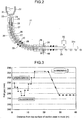
- Fig. 3 shows an exemplary profile of the roll gaps of the slab-supporting rolls in the second embodiment.
- the total rolling reduction is the amount of rolling reduction of the slab 32 from the start to the end of the compression.
- the shorter side width reduction zone 37 is configured such that the roll gaps of the slab-supporting rolls are gradually decreased toward the downstream in the casting direction, and the shorter side of the slab 32 is compressed through such rolls to a reduced thickness. That is, the width of the shorter side of the slab is narrowed.
- the intentional bulging zone 38 is configured such that the roll gaps of the slab-supporting rolls are gradually increased toward the downstream in the casting direction to allow the longer side of the slab 32 except portions adjacent to the shorter side to be intentionally bulged in conformity to the arrangement of the slab-supporting rolls by the action of the ferrostatic pressure of the unsolidified layer 34.
- the portions of the longer side of the slab adjacent to the shorter side are solidly held by the shorter side of the slab that has been completely solidified, and thus maintain the thickness at the start of the intentional bulging. Accordingly, the slab 32 comes to be in contact with the slab-supporting rolls only through the portions of the longer side of the slab that have been intentionally bulged. In the soft reduction zone 36, only the bulged portions of the longer side of the slab undergo compression.
- the shorter side width reduction zone 37 is configured such that the width of the shorter side is reduced with a total rolling reduction of 3 mm to 20 mm.
- a total rolling reduction of 3 mm to 20 mm for the narrowing of the shorter side width the subsequent intentional bulging may be performed with a moderate total amount of bulging. Further, such a total rolling reduction prevents surface cracks in the shorter side of the slab. If the total rolling reduction is less than 3 mm, the narrowing of the shorter side width of the slab is insufficient and the total amount of the subsequent intentional bulging needs to be increased. In such cases, excessively large bulging may cause internal cracks in the slab 32. If, on the other hand, the total rolling reduction for the narrowing of the shorter side width exceeds 20 mm, the shorter side of the slab is subjected to so large a compression strain that surface cracks may occur in the shorter side of the slab to induce a breakout.
- the shorter side width reduction zone 37 it is necessary that a compression force be applied such that the product of the compressing rate multiplied by the casting speed is in the range of 0.3 to 1.0 mm ⁇ m/min 2 . If the product of the compressing rate multiplied by the casting speed is less than 0.3 mm ⁇ m/min 2 , a long distance is required to obtain a prescribed rolling reduction and consequently the shorter side width reduction zone 37 needs to be extended in length, making it impossible to ensure the length for the placement of the intentional bulging zone 38.
- any compression with a value of the above product exceeding 1.0 mm ⁇ m/min 2 is so drastic that a load higher than the withstand load is applied to the slab-supporting rolls to cause damages to the facility as well as to induce internal cracks in the slab 32.
- the compressing rate in the shorter side width reduction zone 37 is expressed as the product of the roll gradient (mm/m) of the slab-supporting rolls disposed with roll gaps gradually decreased toward the downstream in the casting direction, multiplied by the casting speed (m/min).
- the compressing rate in the soft reduction zone 36 is expressed as the product of the roll gradient (mm/m) in the soft reduction zone 36 multiplied by the casting speed (m/min).
- the total amount of bulging is limited to 3 to 20 mm.
- any total amount of bulging that is less than 3 mm does not allow a sufficient amount to be compressed in the soft reduction zone 36 and consequently the central segregation in the slab 32 may not be reduced sufficiently effectively.
- the total amount of intentional bulging is limited to 3 mm or more. If, on the other hand, the total amount of intentional bulging exceeds 20 mm, distortion due to the bulging may induce internal cracks in the slab 32. Thus, in order to prevent internal cracks in the slab 32, the total amount of intentional bulging is limited to 20 mm or less.
- the amount of increase in roll gaps per roll is preferably 1.5 mm or less to prevent the occurrence of cracks at boundaries between the bulged portions and the non-bulged portions in the longer side of the slab.
- the soft reduction zone 36 compression is started from a point where the solid phase fraction in the core portion of the slab is 0.2 or less and is continued to a point where the solid phase fraction in the core portion of the slab reaches 0.9 or more. Even if compression is started after the solid phase fraction in the core portion of the slab has exceeded 0.2, the solute-rich molten steel may have possibly flown to the core by then to cause central segregation. In such cases, the soft reduction cannot produce sufficient effects. The inflow of the molten steel may possibly occur until the solid phase fraction reaches 0.9. If the compression is terminated before such a solid phase fraction is reached, the solute-rich molten steel may flow to the core portion to cause central segregation, and consequently sufficient effects due to the soft reduction cannot be obtained.
- the central segregation in the slab 32 may be reliably prevented by performing the soft reduction at least between a point where the solid phase fraction in the core portion of the slab is 0.2 and a point where the solid phase fraction is 0.9.
- the solid phase fraction in the core portion of the slab may be obtained by two-dimensional heat-transfer solidification calculation similarly to the calculation of the position of a liquidus crater end.
- the solid phase fraction is defined such that the solid phase fraction is 0 before the start of solidification and the solid phase fraction is 1.0 when the solidification is completed.
- the position where the solid phase fraction in the core portion of the slab reaches 1.0 is the solidification completion position 35 (the position of a solidus crater end).
- the position of a liquidus crater end corresponds to the most downstream position where the solid phase fraction in the core portion of the slab is 0.
- the solid phase fraction in the core portion of the slab may be obtained with a solidification completion position detector capable of detecting the solidification completion position 35 online using transverse ultrasonic waves or longitudinal ultrasonic waves.
- a solidification completion position detector detects the solidification completion position 35 online based on the time required for the transverse ultrasonic waves or the longitudinal ultrasonic waves to penetrate or propagate in the slab 32.
- the method is such that the solidification completion position 35 is accurately obtained with the solidification completion position detector and, while using the solidification completion position 35 as the reference, the solid phase fraction in the core portion of the slab is measured in the casting direction with combined use of a technique such as two-dimensional heat-transfer solidification calculation.
- the solid phase fraction in the core portion of the slab may be obtained with a solidification completion position detector that detects the solidification completion position 35 utilizing the nature that the transverse ultrasonic waves do not pass through liquid phases.
- the method is such that an agreement is obtained between the solidification completion position 35 and the position in which a transverse ultrasonic wave sensor is placed and, while using the solidification completion position 35 as the reference, the solid phase fraction in the core portion of the slab is measured in the casting direction with combined use of a technique such as two-dimensional heat-transfer solidification calculation.
- the continuous slab casting machine 21 in the second embodiment of the invention is preferably fitted with an ultrasonic wave sending sensor 39 and an ultrasonic wave receiving sensor 40 that constitute a section in the solidification completion position detector, near the exit of the soft reduction zone 36.
- the solidification completion position detector includes other constituent devices such as a transmission section that transmits signals to the ultrasonic wave sending sensor 39, and a solidification completion position computing section that determines the position 35 of complete solidification of the slab 32 utilizing tools such as calculation expressions based on the signals received by the ultrasonic wave receiving sensor 40.
- the solidification completion position detectors utilizing ultrasonic waves are of such a type that the detectors determine the solidification completion position 35 based on the time required for transverse ultrasonic waves or longitudinal ultrasonic waves to propagate in the slab 32, or are of such a type that the detectors determine the solidification completion position 35 utilizing the nature that the transverse ultrasonic waves do not pass through liquid phases. Any of these solidification completion position detectors may be used as long as the detectors can determine the solidification completion position 35.
- the slab 32 is subjected to a compression force under such conditions that the product of the compressing rate in the soft reduction zone 36 multiplied by the casting speed is in the range of 0.3 to 1.0 mm ⁇ m/min 2 in order to prevent the central segregation in the slab 32 as well as the positive segregation near the core portion. If the product of the compressing rate in the soft reduction zone 36 multiplied by the casting speed is less than 0.3 mm ⁇ m/min 2 , the amount of rolling reduction per unit time is small relative to the amount of solidification shrinkage, and the soft reduction fails to produce sufficient effects in the reduction of central segregation.
- the amount of rolling reduction per unit time is so increased that the unsolidified molten steel is squeezed toward the upstream to possibly cause negative segregation (a type of segregation in which the solute concentration becomes lower than the surrounding regions) in the core portion of the slab.
- the molten steel 31 that has been poured into the casting mold 25 from the tundish 22 through the immersion nozzle 24 is cooled in the casting mold 25 to form a solidified shell 33.
- the slab 32 having this solidified shell 33 as the outer shell and an unsolidified layer 34 inside the slab is continuously drawn in a downward direction away from the casting mold 25 while being supported by the support rolls 26, the guide rolls 27 and the pinch rolls 28 disposed below the casting mold 25.
- the slab 32 is cooled with secondary cooling water in the secondary cooling zone and increases the thickness of the solidified shell 33.
- the slab 32 is compressed to reduce the slab thickness.
- the slab is introduced into the intentional bulging zone 38 to increase the thickness of the longer side of the slab except end portions adjacent to the shorter side, and is completely solidified to the core at the solidification completion position 35 while being subjected to soft reduction in the soft reduction zone 36.
- the slab 32 is cut with a slab cutting machine 30 into slabs 32a.
- the total rolling reduction in the soft reduction zone 36 is adjusted to be equal to or smaller than the total amount of bulging in the intentional bulging zone 38. Further, one, or two or more of the amount of secondary cooling water, the amount of reduction of the width of secondary cooling, and the casting speed are adjusted so that the solid phase fraction in the core portion of the slab will be 0.2 or less at the point where the slab enters the soft reduction zone 36 and also so that the solid phase fraction in the core portion of the slab will be 0.9 or more at the point where the slab exits the soft reduction zone 36.
- the solid phase fraction in the core portion of the slab may be easily controlled by obtaining beforehand the thickness of the solidified shell 33 and the solid phase fraction in the core portion of the slab under various casting conditions using techniques such as two-dimensional heat-transfer solidification calculation.
- the solid phase fraction in the core portion of the slab may be easily controlled by measuring the solid phase fraction in the core portion of the slab online with a solidification completion position detector.
- the "reduction of the width of secondary cooling” means to suspend spraying of cooling water to both edge portions of the longer side of the slab. With the reduction of the width of secondary cooling, the secondary cooling is weakened and the solidification completion position 35 is generally shifted toward the downstream in the casting direction.
- the longer side of the slab is first compressed at a stage where the solidified shell 33 still has a low deformation strength, and thereby the width of the shorter side of the slab 32 is reduced by 3 to 20 mm compared to the size immediately below the lower end of the casting mold. Consequently, the total amount of intentional bulging may be decreased and internal cracks in the slab 32 may be prevented. Further, the soft reduction is performed while satisfying the specific timing of the soft reduction as well as the specific product of the compressing rate multiplied by the casting speed, and thus the central segregation in the slab 32 may be stably reduced.
- the second embodiment of the invention may be similarly carried out with a curved continuous casting machine or a vertical continuous casting machine.
- the effects of the soft reduction in the prevention of the central segregation in the slab 32 are also affected by the type of solidified structures of the slab 32. Specifically, in the case where the solidified structure in the core portion of the slab 32 is an equiaxed crystal structure, the solute-rich molten steel serving as a cause of semi-macro segregation is allowed to be present among equiaxed crystals, and the effects of the soft reduction in reducing central segregation are decreased.
- the casting conditions be controlled so that the solidified structure in the core portion of the slab 32 will be a columnar crystal structure.
- the first embodiment of the invention was applied to tests in which a slab was intentionally bulged and was thereafter compressed with use of a continuous slab casting machine illustrated in Fig. 1 .
- the slab was 2100 mm in width and 250 mm in thickness (D 0 ) immediately before the start of bulging.
- the casting speed was 0.85 to 1.2 m/min, and the relative amount of water for the secondary cooling of the slab was 1.0 to 2.0 L/steel-kg.
- the total amount of intentional bulging was 3.0 mm to 21.0 mm.
- the tests were performed under various conditions while changing the solidified shell thickness immediately before the bulging, the gradient of roll gaps in the bulging, the length in the casting direction of a zone in which the thickness of the bulged slab was maintained constant (a zone in which guide rolls were disposed with constant roll gaps), and the total amount of bulging.
- the steels that were cast were steels for steel plates having a carbon concentration of 0.05 to 0.08 mass%.
- a full-width test piece was sampled over a length of 1000 mm in the casting direction from a portion of the slab formed in a steady casting period.
- a transverse plane sample having a thickness of 50 mm was cut out from this full-width test piece.
- manganese (Mn) was analyzed with EPMA (electron probe micro analyzer) in the direction of the thickness of the slab.
- Fig. 4 is a view illustrating the transverse plane sampling position and the position of the manganese analysis with EPMA.
- the manganese analysis with EPMA examined the occurrence of central segregation in the core portion of the slab, as well as the occurrence of positive segregation (a type of segregation in which the concentration of solute components is increased from the initial concentration) or negative segregation (a type of segregation in which the concentration of solute components is decreased from the initial concentration) near the core portion of the slab.
- the values of manganese concentration measured at the various positions in the transverse plane sample were each divided by the manganese concentration in the analysis sample collected from the molten steel in the ladle (Manganese concentration (mass%) at each position in the transverse plane sample/Manganese concentration (mass%) in the analysis sample collected from the molten steel in the ladle), thereby determining the degree of segregation.
- the distribution of the degrees of segregation in the slab thickness direction was studied.
- the calculation of the degree of segregation in the slab adopted the larger value of the concentrations in the central segregation and the positive segregation near the core portion of the slab. Further, the presence or absence of internal cracks was studied by a sulfur print test of the transverse plane sample.
- the slabs were free from central segregation and positive segregation near the core portion, and were also free from internal cracks. These results were because in the tests Nos. 1 to 6, all the five conditions, namely, the solidified shell thickness immediately before the bulging, the total amount of bulging, the length in the casting direction of the zone in which the thickness of the bulged slab was maintained constant, the product of the compressing rate multiplied by the casting speed, and the solid phase fraction in the core portion of the slab during the compression were within the ranges of the first embodiment of the invention, and further the gradient of roll gaps in the bulging was in the preferred range of the first embodiment of the invention.
- the gradient of roll gaps in the bulging was outside the preferred range of the first embodiment of the invention, and consequently slight internal cracks were generated.
- the solidified shell thickness immediately before the bulging was as large as 25 mm, and the internal cracks were checked to a slight extent.
- the other conditions were within the ranges of the first embodiment of the invention, and the slab was free from central segregation and positive segregation near the core portion.
- the thickness of the bulged slab was maintained constant over a length in the casting direction outside the range of the first embodiment of the invention, and consequently positive segregation occurred near the core portion of the slab with a degree of segregation of 1.090. This result was because the length in the casting direction of the zone in which the thickness of the bulged slab was maintained constant was too short and the compression failed to apply a uniform reduction in the direction of the width of the slab.
- the solidified shell thickness immediately before the bulging was outside the range of the first embodiment of the invention, and further the gradient of roll gaps in the bulging was outside the preferred range of the first embodiment of the invention. Consequently, internal cracks were generated in the slab.
- the other conditions were within the ranges of the first embodiment of the invention, and the slab was free from central segregation and positive segregation near the core portion.
- the slab was compressed when the solid phase fraction in the core portion of the slab was 0.95.
- the compression produced no effects because the timing of the compression was outside the range of the first embodiment of the invention. Consequently, positive segregation occurred near the core portion of the slab with a degree of segregation of 1.198.
- no internal cracks were generated because the solidified shell thickness immediately before the bulging, and the total amount of bulging were within the ranges of the first embodiment of the invention, and the gradient of roll gaps in the bulging was in the preferred range of the first embodiment of the invention.
- the second embodiment of the invention was applied to casting tests with use of a continuous slab casting machine configured as illustrated in Fig. 2 (Inventive Examples: test Nos. 21 to 25). Slabs for steel plates having a carbon content of 0.05 to 0.08 mass% were cast. The slab width was 2100 mm. The thickness of the slab was 250 mm immediately below the casting mold. The casting speed was 0.85 to 1.42 m/min, and the relative amount of water for the secondary cooling of the slab was 1 to 2 L/steel-kg.
- the total rolling reduction in the shorter side width reduction zone was 3.0 to 20.0 mm, and the total amount of bulging in the intentional bulging zone was 3.0 to 20.0 mm.
- the total rolling reduction in the soft reduction zone was equal to or smaller than the total amount of bulging.
- the solid phase fraction in the core portion of the slab at the completion of the soft reduction was 0.9 or more.
- a full-width test piece was sampled over a length of 1000 mm in the casting direction from a portion of the slab formed in a steady casting period.
- a transverse plane sample having a thickness of 50 mm was cut out from this full-width test piece.
- manganese was analyzed with EPMA in the direction of the thickness of the slab.
- the manganese analysis with EPMA examined the occurrence of central segregation in the core portion of the slab, as well as the occurrence of positive segregation (a type of segregation in which the concentration of solute components is increased from the initial concentration) or negative segregation (a type of segregation in which the concentration of solute components is decreased from the initial concentration) near the core portion of the slab.
- the values of manganese concentration measured at the various positions in the transverse plane sample were each divided by the manganese concentration in the analysis sample (mass% Mn 0 ) collected from the molten steel in the ladle before casting (mass% Mn/mass% Mn 0 ), thereby determining the degree of segregation.
- the distribution of the degrees of segregation in the slab thickness direction was studied.
- the calculation of the degree of segregation in the slab adopted the larger value of the concentrations in the central segregation and the positive segregation near the core portion of the slab.
- the presence or absence of internal cracks was studied by a sulfur print test of the transverse plane sample. The test conditions and the results of the studies are described in Table 2.
- the slabs were free from central segregation in the core portion and positive segregation near the core portion of the slab, and were also free from internal cracks.
- the total rolling reduction in the shorter side width reduction zone was 23.0 mm and was outside the range of the second embodiment of the invention.
- the other conditions were within the ranges of the second embodiment of the invention, but internal cracks were generated in the slab due to the excessively large total rolling reduction in the shorter side width reduction zone.
- the total amount of intentional bulging was 30.0 mm and was outside the range of the second embodiment of the invention.
- the other conditions were within the ranges of the second embodiment of the invention, but internal cracks were generated in the slab due to the excessively large total amount of bulging.
- the product of the compressing rate in the soft reduction multiplied by the casting speed was 0.2 and was outside the range of the second embodiment of the invention.
- the slab was free from internal cracks, central segregation was observed with a degree of manganese segregation of 1.080 due to insufficient soft reduction.
- the total rolling reduction in the shorter side width reduction zone was 2.0 mm and was outside the range of the second embodiment of the invention.
- the other conditions were within the ranges of the second embodiment of the invention.
- internal cracks were not generated, but slight central segregation was observed with a degree of manganese segregation of 1.040. This result was probably because the total rolling reduction in the shorter side width reduction zone was so small that the thickness of the shorter side was not effectively reduced and consequently the effects of the soft reduction were decreased.
- the soft reduction was performed after the solid phase fraction in the core portion of the slab reached 1.0 (complete solidification) in contrast to the requirement in the second embodiment of the invention.
- the soft reduction after the completion of solidification produced no effects, and central segregation was observed with a degree of manganese segregation of 1.080.
Landscapes
- Engineering & Computer Science (AREA)
- Mechanical Engineering (AREA)
- Continuous Casting (AREA)
Applications Claiming Priority (3)
| Application Number | Priority Date | Filing Date | Title |
|---|---|---|---|
| JP2012169182 | 2012-07-31 | ||
| JP2013099056 | 2013-05-09 | ||
| PCT/JP2013/004476 WO2014020860A1 (ja) | 2012-07-31 | 2013-07-23 | 鋼の連続鋳造方法 |
Publications (3)
| Publication Number | Publication Date |
|---|---|
| EP2881196A1 EP2881196A1 (en) | 2015-06-10 |
| EP2881196A4 EP2881196A4 (en) | 2015-08-19 |
| EP2881196B1 true EP2881196B1 (en) | 2016-09-14 |
Family
ID=50027569
Family Applications (1)
| Application Number | Title | Priority Date | Filing Date |
|---|---|---|---|
| EP13825044.4A Active EP2881196B1 (en) | 2012-07-31 | 2013-07-23 | Method for continuously casting steel |
Country Status (7)
| Country | Link |
|---|---|
| EP (1) | EP2881196B1 (pt) |
| JP (1) | JP5522324B1 (pt) |
| KR (1) | KR101639349B1 (pt) |
| CN (1) | CN104507598B (pt) |
| BR (1) | BR112015001929B1 (pt) |
| IN (1) | IN2014DN10142A (pt) |
| WO (1) | WO2014020860A1 (pt) |
Families Citing this family (6)
| Publication number | Priority date | Publication date | Assignee | Title |
|---|---|---|---|---|
| JP6075336B2 (ja) * | 2014-07-15 | 2017-02-08 | Jfeスチール株式会社 | 鋼の連続鋳造方法 |
| JP6365604B2 (ja) * | 2015-07-22 | 2018-08-01 | Jfeスチール株式会社 | 鋼の連続鋳造方法 |
| KR101941877B1 (ko) * | 2015-09-24 | 2019-01-25 | (주)포스코 | 주편의 연속 주조 방법 |
| WO2018055799A1 (ja) * | 2016-09-21 | 2018-03-29 | Jfeスチール株式会社 | 鋼の連続鋳造方法 |
| CN109689247B (zh) * | 2016-09-21 | 2021-12-10 | 杰富意钢铁株式会社 | 钢的连续铸造方法 |
| BR112020017364A2 (pt) * | 2018-03-02 | 2020-12-15 | Jfe Steel Corporation | Método de vazamento contínuo de aço |
Family Cites Families (19)
| Publication number | Priority date | Publication date | Assignee | Title |
|---|---|---|---|---|
| JPH02235558A (ja) * | 1989-03-09 | 1990-09-18 | Nkk Corp | ブルーム連続鋳造方法 |
| JPH06218509A (ja) | 1993-01-26 | 1994-08-09 | Kawasaki Steel Corp | 連続鋳造における鋳片ストランドの大圧下方法 |
| JP3064832B2 (ja) | 1994-11-10 | 2000-07-12 | 住友金属工業株式会社 | 連続鋳造方法 |
| JP2980006B2 (ja) | 1995-08-18 | 1999-11-22 | 住友金属工業株式会社 | 連続鋳造方法 |
| JP3055453B2 (ja) | 1996-01-29 | 2000-06-26 | 住友金属工業株式会社 | 連続鋳造方法 |
| JP3147803B2 (ja) * | 1997-02-13 | 2001-03-19 | 住友金属工業株式会社 | 連続鋳造方法 |
| JP3225894B2 (ja) * | 1997-07-17 | 2001-11-05 | 住友金属工業株式会社 | 連続鋳造方法 |
| JP3111954B2 (ja) * | 1997-11-28 | 2000-11-27 | 住友金属工業株式会社 | 連続鋳造方法 |
| JP3149834B2 (ja) * | 1997-11-28 | 2001-03-26 | 住友金属工業株式会社 | 鋼スラブ連続鋳造方法 |
| JP3275835B2 (ja) * | 1998-06-12 | 2002-04-22 | 住友金属工業株式会社 | 連続鋳造方法および連続鋳造機 |
| JP3360618B2 (ja) * | 1998-08-26 | 2002-12-24 | 住友金属工業株式会社 | 連続鋳造方法 |
| JP3402251B2 (ja) | 1999-04-06 | 2003-05-06 | 住友金属工業株式会社 | 連続鋳造方法 |
| JP3994848B2 (ja) * | 2002-10-22 | 2007-10-24 | 住友金属工業株式会社 | 鋼の連続鋳造方法 |
| JP4508087B2 (ja) * | 2005-11-17 | 2010-07-21 | 住友金属工業株式会社 | 連続鋳造方法および連続鋳造鋳片 |
| JP5145746B2 (ja) * | 2007-03-29 | 2013-02-20 | Jfeスチール株式会社 | 連続鋳造鋳片の製造方法、連続鋳造機 |
| KR101038552B1 (ko) * | 2007-11-19 | 2011-06-03 | 주식회사 포스코 | 연속주조주편 및 그 제조방법 |
| JP5045408B2 (ja) * | 2007-12-10 | 2012-10-10 | Jfeスチール株式会社 | 連続鋳造鋳片の製造方法 |
| JP5600929B2 (ja) * | 2008-12-10 | 2014-10-08 | Jfeスチール株式会社 | 連続鋳造鋳片の製造方法 |
| WO2010119680A1 (ja) * | 2009-04-14 | 2010-10-21 | 新日本製鐵株式会社 | 連続鋳造設備 |
-
2013
- 2013-07-23 IN IN10142DEN2014 patent/IN2014DN10142A/en unknown
- 2013-07-23 CN CN201380040849.5A patent/CN104507598B/zh active Active
- 2013-07-23 BR BR112015001929A patent/BR112015001929B1/pt active IP Right Grant
- 2013-07-23 EP EP13825044.4A patent/EP2881196B1/en active Active
- 2013-07-23 JP JP2013553547A patent/JP5522324B1/ja active Active
- 2013-07-23 WO PCT/JP2013/004476 patent/WO2014020860A1/ja active Application Filing
- 2013-07-23 KR KR1020157001287A patent/KR101639349B1/ko active IP Right Grant
Also Published As
| Publication number | Publication date |
|---|---|
| KR101639349B1 (ko) | 2016-07-13 |
| JP5522324B1 (ja) | 2014-06-18 |
| BR112015001929B1 (pt) | 2019-08-13 |
| IN2014DN10142A (pt) | 2015-08-21 |
| BR112015001929A2 (pt) | 2016-08-02 |
| KR20150023796A (ko) | 2015-03-05 |
| EP2881196A4 (en) | 2015-08-19 |
| EP2881196A1 (en) | 2015-06-10 |
| CN104507598A (zh) | 2015-04-08 |
| WO2014020860A1 (ja) | 2014-02-06 |
| JPWO2014020860A1 (ja) | 2016-07-21 |
| BR112015001929A8 (pt) | 2018-04-03 |
| CN104507598B (zh) | 2017-03-08 |
Similar Documents
| Publication | Publication Date | Title |
|---|---|---|
| EP2881196B1 (en) | Method for continuously casting steel | |
| JP5600929B2 (ja) | 連続鋳造鋳片の製造方法 | |
| JP6115735B2 (ja) | 鋼の連続鋳造方法 | |
| JP5962625B2 (ja) | 鋼の連続鋳造方法 | |
| JP6384679B2 (ja) | 熱延鋼板の製造方法 | |
| EP3488947B1 (en) | Continuous steel casting method | |
| JP6075336B2 (ja) | 鋼の連続鋳造方法 | |
| JP5245800B2 (ja) | 連続鋳造用鋳型及び鋼の連続鋳造方法 | |
| JP3511973B2 (ja) | 連続鋳造方法 | |
| EP3782747B1 (en) | Shaping and soft reduction method for the continuous casting of steel | |
| EP3760339B1 (en) | Continuous steel casting method using soft reduction with small rolling load | |
| JP5929836B2 (ja) | 鋼の連続鋳造方法 | |
| JP2001334353A (ja) | 鋼の連続鋳造方法 | |
| JPH09206903A (ja) | 連続鋳造方法 | |
| WO2024004447A1 (ja) | 鋼の連続鋳造方法 | |
| JP7371821B1 (ja) | 鋼の連続鋳造方法 | |
| JP3398093B2 (ja) | 連続鋳造設備 | |
| JP3275828B2 (ja) | 連続鋳造方法 | |
| JP2004307931A (ja) | 連続鋳造鋳片およびその鋳造方法 | |
| JP5195636B2 (ja) | 連続鋳造鋳片の製造方法 | |
| JP3876768B2 (ja) | 連続鋳造方法 | |
| JPH10128512A (ja) | 丸ビレットの未凝固圧下製造方法 | |
| JP3395717B2 (ja) | 連続鋳造方法 | |
| JP2002066705A (ja) | 連続鋳造鋳片、その鋳造方法および厚鋼板の製造方法 | |
| JP2000237857A (ja) | 連続鋳造方法 |
Legal Events
| Date | Code | Title | Description |
|---|---|---|---|
| PUAI | Public reference made under article 153(3) epc to a published international application that has entered the european phase |
Free format text: ORIGINAL CODE: 0009012 |
|
| 17P | Request for examination filed |
Effective date: 20150223 |
|
| AK | Designated contracting states |
Kind code of ref document: A1 Designated state(s): AL AT BE BG CH CY CZ DE DK EE ES FI FR GB GR HR HU IE IS IT LI LT LU LV MC MK MT NL NO PL PT RO RS SE SI SK SM TR |
|
| AX | Request for extension of the european patent |
Extension state: BA ME |
|
| RA4 | Supplementary search report drawn up and despatched (corrected) |
Effective date: 20150722 |
|
| RIC1 | Information provided on ipc code assigned before grant |
Ipc: B22D 11/20 20060101ALI20150716BHEP Ipc: B22D 11/041 20060101ALI20150716BHEP Ipc: B22D 11/128 20060101AFI20150716BHEP Ipc: B22D 11/16 20060101ALI20150716BHEP Ipc: B22D 11/12 20060101ALI20150716BHEP |
|
| DAX | Request for extension of the european patent (deleted) | ||
| GRAP | Despatch of communication of intention to grant a patent |
Free format text: ORIGINAL CODE: EPIDOSNIGR1 |
|
| INTG | Intention to grant announced |
Effective date: 20160404 |
|
| GRAS | Grant fee paid |
Free format text: ORIGINAL CODE: EPIDOSNIGR3 |
|
| GRAA | (expected) grant |
Free format text: ORIGINAL CODE: 0009210 |
|
| AK | Designated contracting states |
Kind code of ref document: B1 Designated state(s): AL AT BE BG CH CY CZ DE DK EE ES FI FR GB GR HR HU IE IS IT LI LT LU LV MC MK MT NL NO PL PT RO RS SE SI SK SM TR |
|
| REG | Reference to a national code |
Ref country code: GB Ref legal event code: FG4D |
|
| REG | Reference to a national code |
Ref country code: CH Ref legal event code: EP |
|
| REG | Reference to a national code |
Ref country code: IE Ref legal event code: FG4D |
|
| REG | Reference to a national code |
Ref country code: AT Ref legal event code: REF Ref document number: 828367 Country of ref document: AT Kind code of ref document: T Effective date: 20161015 |
|
| REG | Reference to a national code |
Ref country code: DE Ref legal event code: R096 Ref document number: 602013011747 Country of ref document: DE |
|
| REG | Reference to a national code |
Ref country code: LT Ref legal event code: MG4D |
|
| REG | Reference to a national code |
Ref country code: NL Ref legal event code: MP Effective date: 20160914 |
|
| PG25 | Lapsed in a contracting state [announced via postgrant information from national office to epo] |
Ref country code: FI Free format text: LAPSE BECAUSE OF FAILURE TO SUBMIT A TRANSLATION OF THE DESCRIPTION OR TO PAY THE FEE WITHIN THE PRESCRIBED TIME-LIMIT Effective date: 20160914 Ref country code: NO Free format text: LAPSE BECAUSE OF FAILURE TO SUBMIT A TRANSLATION OF THE DESCRIPTION OR TO PAY THE FEE WITHIN THE PRESCRIBED TIME-LIMIT Effective date: 20161214 Ref country code: LT Free format text: LAPSE BECAUSE OF FAILURE TO SUBMIT A TRANSLATION OF THE DESCRIPTION OR TO PAY THE FEE WITHIN THE PRESCRIBED TIME-LIMIT Effective date: 20160914 Ref country code: RS Free format text: LAPSE BECAUSE OF FAILURE TO SUBMIT A TRANSLATION OF THE DESCRIPTION OR TO PAY THE FEE WITHIN THE PRESCRIBED TIME-LIMIT Effective date: 20160914 Ref country code: HR Free format text: LAPSE BECAUSE OF FAILURE TO SUBMIT A TRANSLATION OF THE DESCRIPTION OR TO PAY THE FEE WITHIN THE PRESCRIBED TIME-LIMIT Effective date: 20160914 |
|
| PG25 | Lapsed in a contracting state [announced via postgrant information from national office to epo] |
Ref country code: GR Free format text: LAPSE BECAUSE OF FAILURE TO SUBMIT A TRANSLATION OF THE DESCRIPTION OR TO PAY THE FEE WITHIN THE PRESCRIBED TIME-LIMIT Effective date: 20161215 Ref country code: NL Free format text: LAPSE BECAUSE OF FAILURE TO SUBMIT A TRANSLATION OF THE DESCRIPTION OR TO PAY THE FEE WITHIN THE PRESCRIBED TIME-LIMIT Effective date: 20160914 Ref country code: LV Free format text: LAPSE BECAUSE OF FAILURE TO SUBMIT A TRANSLATION OF THE DESCRIPTION OR TO PAY THE FEE WITHIN THE PRESCRIBED TIME-LIMIT Effective date: 20160914 Ref country code: SE Free format text: LAPSE BECAUSE OF FAILURE TO SUBMIT A TRANSLATION OF THE DESCRIPTION OR TO PAY THE FEE WITHIN THE PRESCRIBED TIME-LIMIT Effective date: 20160914 |
|
| PG25 | Lapsed in a contracting state [announced via postgrant information from national office to epo] |
Ref country code: RO Free format text: LAPSE BECAUSE OF FAILURE TO SUBMIT A TRANSLATION OF THE DESCRIPTION OR TO PAY THE FEE WITHIN THE PRESCRIBED TIME-LIMIT Effective date: 20160914 Ref country code: EE Free format text: LAPSE BECAUSE OF FAILURE TO SUBMIT A TRANSLATION OF THE DESCRIPTION OR TO PAY THE FEE WITHIN THE PRESCRIBED TIME-LIMIT Effective date: 20160914 |
|
| PG25 | Lapsed in a contracting state [announced via postgrant information from national office to epo] |
Ref country code: ES Free format text: LAPSE BECAUSE OF FAILURE TO SUBMIT A TRANSLATION OF THE DESCRIPTION OR TO PAY THE FEE WITHIN THE PRESCRIBED TIME-LIMIT Effective date: 20160914 Ref country code: PT Free format text: LAPSE BECAUSE OF FAILURE TO SUBMIT A TRANSLATION OF THE DESCRIPTION OR TO PAY THE FEE WITHIN THE PRESCRIBED TIME-LIMIT Effective date: 20170116 Ref country code: SM Free format text: LAPSE BECAUSE OF FAILURE TO SUBMIT A TRANSLATION OF THE DESCRIPTION OR TO PAY THE FEE WITHIN THE PRESCRIBED TIME-LIMIT Effective date: 20160914 Ref country code: PL Free format text: LAPSE BECAUSE OF FAILURE TO SUBMIT A TRANSLATION OF THE DESCRIPTION OR TO PAY THE FEE WITHIN THE PRESCRIBED TIME-LIMIT Effective date: 20160914 Ref country code: IS Free format text: LAPSE BECAUSE OF FAILURE TO SUBMIT A TRANSLATION OF THE DESCRIPTION OR TO PAY THE FEE WITHIN THE PRESCRIBED TIME-LIMIT Effective date: 20170114 Ref country code: BG Free format text: LAPSE BECAUSE OF FAILURE TO SUBMIT A TRANSLATION OF THE DESCRIPTION OR TO PAY THE FEE WITHIN THE PRESCRIBED TIME-LIMIT Effective date: 20161214 Ref country code: BE Free format text: LAPSE BECAUSE OF FAILURE TO SUBMIT A TRANSLATION OF THE DESCRIPTION OR TO PAY THE FEE WITHIN THE PRESCRIBED TIME-LIMIT Effective date: 20160914 Ref country code: CZ Free format text: LAPSE BECAUSE OF FAILURE TO SUBMIT A TRANSLATION OF THE DESCRIPTION OR TO PAY THE FEE WITHIN THE PRESCRIBED TIME-LIMIT Effective date: 20160914 Ref country code: SK Free format text: LAPSE BECAUSE OF FAILURE TO SUBMIT A TRANSLATION OF THE DESCRIPTION OR TO PAY THE FEE WITHIN THE PRESCRIBED TIME-LIMIT Effective date: 20160914 |
|
| REG | Reference to a national code |
Ref country code: DE Ref legal event code: R097 Ref document number: 602013011747 Country of ref document: DE |
|
| PLBE | No opposition filed within time limit |
Free format text: ORIGINAL CODE: 0009261 |
|
| STAA | Information on the status of an ep patent application or granted ep patent |
Free format text: STATUS: NO OPPOSITION FILED WITHIN TIME LIMIT |
|
| PG25 | Lapsed in a contracting state [announced via postgrant information from national office to epo] |
Ref country code: DK Free format text: LAPSE BECAUSE OF FAILURE TO SUBMIT A TRANSLATION OF THE DESCRIPTION OR TO PAY THE FEE WITHIN THE PRESCRIBED TIME-LIMIT Effective date: 20160914 |
|
| 26N | No opposition filed |
Effective date: 20170615 |
|
| PG25 | Lapsed in a contracting state [announced via postgrant information from national office to epo] |
Ref country code: SI Free format text: LAPSE BECAUSE OF FAILURE TO SUBMIT A TRANSLATION OF THE DESCRIPTION OR TO PAY THE FEE WITHIN THE PRESCRIBED TIME-LIMIT Effective date: 20160914 |
|
| REG | Reference to a national code |
Ref country code: CH Ref legal event code: PL |
|
| GBPC | Gb: european patent ceased through non-payment of renewal fee |
Effective date: 20170723 |
|
| REG | Reference to a national code |
Ref country code: IE Ref legal event code: MM4A |
|
| REG | Reference to a national code |
Ref country code: FR Ref legal event code: ST Effective date: 20180330 |
|
| PG25 | Lapsed in a contracting state [announced via postgrant information from national office to epo] |
Ref country code: IE Free format text: LAPSE BECAUSE OF NON-PAYMENT OF DUE FEES Effective date: 20170723 Ref country code: LI Free format text: LAPSE BECAUSE OF NON-PAYMENT OF DUE FEES Effective date: 20170731 Ref country code: GB Free format text: LAPSE BECAUSE OF NON-PAYMENT OF DUE FEES Effective date: 20170723 Ref country code: CH Free format text: LAPSE BECAUSE OF NON-PAYMENT OF DUE FEES Effective date: 20170731 |
|
| PG25 | Lapsed in a contracting state [announced via postgrant information from national office to epo] |
Ref country code: FR Free format text: LAPSE BECAUSE OF NON-PAYMENT OF DUE FEES Effective date: 20170731 |
|
| PG25 | Lapsed in a contracting state [announced via postgrant information from national office to epo] |
Ref country code: LU Free format text: LAPSE BECAUSE OF NON-PAYMENT OF DUE FEES Effective date: 20170723 |
|
| PG25 | Lapsed in a contracting state [announced via postgrant information from national office to epo] |
Ref country code: MT Free format text: LAPSE BECAUSE OF NON-PAYMENT OF DUE FEES Effective date: 20170723 |
|
| PG25 | Lapsed in a contracting state [announced via postgrant information from national office to epo] |
Ref country code: AL Free format text: LAPSE BECAUSE OF FAILURE TO SUBMIT A TRANSLATION OF THE DESCRIPTION OR TO PAY THE FEE WITHIN THE PRESCRIBED TIME-LIMIT Effective date: 20160914 |
|
| PG25 | Lapsed in a contracting state [announced via postgrant information from national office to epo] |
Ref country code: MC Free format text: LAPSE BECAUSE OF FAILURE TO SUBMIT A TRANSLATION OF THE DESCRIPTION OR TO PAY THE FEE WITHIN THE PRESCRIBED TIME-LIMIT Effective date: 20160914 Ref country code: HU Free format text: LAPSE BECAUSE OF FAILURE TO SUBMIT A TRANSLATION OF THE DESCRIPTION OR TO PAY THE FEE WITHIN THE PRESCRIBED TIME-LIMIT; INVALID AB INITIO Effective date: 20130723 |
|
| REG | Reference to a national code |
Ref country code: AT Ref legal event code: UEP Ref document number: 828367 Country of ref document: AT Kind code of ref document: T Effective date: 20160914 |
|
| PG25 | Lapsed in a contracting state [announced via postgrant information from national office to epo] |
Ref country code: CY Free format text: LAPSE BECAUSE OF FAILURE TO SUBMIT A TRANSLATION OF THE DESCRIPTION OR TO PAY THE FEE WITHIN THE PRESCRIBED TIME-LIMIT Effective date: 20160914 |
|
| PG25 | Lapsed in a contracting state [announced via postgrant information from national office to epo] |
Ref country code: MK Free format text: LAPSE BECAUSE OF FAILURE TO SUBMIT A TRANSLATION OF THE DESCRIPTION OR TO PAY THE FEE WITHIN THE PRESCRIBED TIME-LIMIT Effective date: 20160914 |
|
| PG25 | Lapsed in a contracting state [announced via postgrant information from national office to epo] |
Ref country code: TR Free format text: LAPSE BECAUSE OF FAILURE TO SUBMIT A TRANSLATION OF THE DESCRIPTION OR TO PAY THE FEE WITHIN THE PRESCRIBED TIME-LIMIT Effective date: 20160914 |
|
| REG | Reference to a national code |
Ref country code: DE Ref legal event code: R082 Ref document number: 602013011747 Country of ref document: DE Representative=s name: HL KEMPNER PATENTANWAELTE, SOLICITORS (ENGLAND, DE Ref country code: DE Ref legal event code: R082 Ref document number: 602013011747 Country of ref document: DE Representative=s name: HL KEMPNER PATENTANWALT, RECHTSANWALT, SOLICIT, DE |
|
| PGFP | Annual fee paid to national office [announced via postgrant information from national office to epo] |
Ref country code: IT Payment date: 20230612 Year of fee payment: 11 |
|
| PGFP | Annual fee paid to national office [announced via postgrant information from national office to epo] |
Ref country code: AT Payment date: 20230626 Year of fee payment: 11 |
|
| PGFP | Annual fee paid to national office [announced via postgrant information from national office to epo] |
Ref country code: DE Payment date: 20230531 Year of fee payment: 11 |