EP2880236B1 - Fenstereinheit aus vakuumisoliertem glas mit einer fängerstruktur und verfahren zur herstellung davon - Google Patents
Fenstereinheit aus vakuumisoliertem glas mit einer fängerstruktur und verfahren zur herstellung davon Download PDFInfo
- Publication number
- EP2880236B1 EP2880236B1 EP13742574.0A EP13742574A EP2880236B1 EP 2880236 B1 EP2880236 B1 EP 2880236B1 EP 13742574 A EP13742574 A EP 13742574A EP 2880236 B1 EP2880236 B1 EP 2880236B1
- Authority
- EP
- European Patent Office
- Prior art keywords
- getter
- recess
- substrate
- vig
- window unit
- Prior art date
- Legal status (The legal status is an assumption and is not a legal conclusion. Google has not performed a legal analysis and makes no representation as to the accuracy of the status listed.)
- Active
Links
Images






Classifications
-
- E—FIXED CONSTRUCTIONS
- E06—DOORS, WINDOWS, SHUTTERS, OR ROLLER BLINDS IN GENERAL; LADDERS
- E06B—FIXED OR MOVABLE CLOSURES FOR OPENINGS IN BUILDINGS, VEHICLES, FENCES OR LIKE ENCLOSURES IN GENERAL, e.g. DOORS, WINDOWS, BLINDS, GATES
- E06B3/00—Window sashes, door leaves, or like elements for closing wall or like openings; Layout of fixed or moving closures, e.g. windows in wall or like openings; Features of rigidly-mounted outer frames relating to the mounting of wing frames
- E06B3/66—Units comprising two or more parallel glass or like panes permanently secured together
- E06B3/6612—Evacuated glazing units
-
- E—FIXED CONSTRUCTIONS
- E06—DOORS, WINDOWS, SHUTTERS, OR ROLLER BLINDS IN GENERAL; LADDERS
- E06B—FIXED OR MOVABLE CLOSURES FOR OPENINGS IN BUILDINGS, VEHICLES, FENCES OR LIKE ENCLOSURES IN GENERAL, e.g. DOORS, WINDOWS, BLINDS, GATES
- E06B3/00—Window sashes, door leaves, or like elements for closing wall or like openings; Layout of fixed or moving closures, e.g. windows in wall or like openings; Features of rigidly-mounted outer frames relating to the mounting of wing frames
- E06B3/66—Units comprising two or more parallel glass or like panes permanently secured together
- E06B3/663—Elements for spacing panes
-
- E—FIXED CONSTRUCTIONS
- E06—DOORS, WINDOWS, SHUTTERS, OR ROLLER BLINDS IN GENERAL; LADDERS
- E06B—FIXED OR MOVABLE CLOSURES FOR OPENINGS IN BUILDINGS, VEHICLES, FENCES OR LIKE ENCLOSURES IN GENERAL, e.g. DOORS, WINDOWS, BLINDS, GATES
- E06B3/00—Window sashes, door leaves, or like elements for closing wall or like openings; Layout of fixed or moving closures, e.g. windows in wall or like openings; Features of rigidly-mounted outer frames relating to the mounting of wing frames
- E06B3/66—Units comprising two or more parallel glass or like panes permanently secured together
- E06B3/677—Evacuating or filling the gap between the panes ; Equilibration of inside and outside pressure; Preventing condensation in the gap between the panes; Cleaning the gap between the panes
-
- E—FIXED CONSTRUCTIONS
- E06—DOORS, WINDOWS, SHUTTERS, OR ROLLER BLINDS IN GENERAL; LADDERS
- E06B—FIXED OR MOVABLE CLOSURES FOR OPENINGS IN BUILDINGS, VEHICLES, FENCES OR LIKE ENCLOSURES IN GENERAL, e.g. DOORS, WINDOWS, BLINDS, GATES
- E06B3/00—Window sashes, door leaves, or like elements for closing wall or like openings; Layout of fixed or moving closures, e.g. windows in wall or like openings; Features of rigidly-mounted outer frames relating to the mounting of wing frames
- E06B3/66—Units comprising two or more parallel glass or like panes permanently secured together
- E06B3/677—Evacuating or filling the gap between the panes ; Equilibration of inside and outside pressure; Preventing condensation in the gap between the panes; Cleaning the gap between the panes
- E06B3/6775—Evacuating or filling the gap during assembly
-
- E—FIXED CONSTRUCTIONS
- E06—DOORS, WINDOWS, SHUTTERS, OR ROLLER BLINDS IN GENERAL; LADDERS
- E06B—FIXED OR MOVABLE CLOSURES FOR OPENINGS IN BUILDINGS, VEHICLES, FENCES OR LIKE ENCLOSURES IN GENERAL, e.g. DOORS, WINDOWS, BLINDS, GATES
- E06B9/00—Screening or protective devices for wall or similar openings, with or without operating or securing mechanisms; Closures of similar construction
- E06B9/24—Screens or other constructions affording protection against light, especially against sunshine; Similar screens for privacy or appearance; Slat blinds
-
- E—FIXED CONSTRUCTIONS
- E06—DOORS, WINDOWS, SHUTTERS, OR ROLLER BLINDS IN GENERAL; LADDERS
- E06B—FIXED OR MOVABLE CLOSURES FOR OPENINGS IN BUILDINGS, VEHICLES, FENCES OR LIKE ENCLOSURES IN GENERAL, e.g. DOORS, WINDOWS, BLINDS, GATES
- E06B9/00—Screening or protective devices for wall or similar openings, with or without operating or securing mechanisms; Closures of similar construction
- E06B9/24—Screens or other constructions affording protection against light, especially against sunshine; Similar screens for privacy or appearance; Slat blinds
- E06B2009/2417—Light path control; means to control reflection
-
- Y—GENERAL TAGGING OF NEW TECHNOLOGICAL DEVELOPMENTS; GENERAL TAGGING OF CROSS-SECTIONAL TECHNOLOGIES SPANNING OVER SEVERAL SECTIONS OF THE IPC; TECHNICAL SUBJECTS COVERED BY FORMER USPC CROSS-REFERENCE ART COLLECTIONS [XRACs] AND DIGESTS
- Y02—TECHNOLOGIES OR APPLICATIONS FOR MITIGATION OR ADAPTATION AGAINST CLIMATE CHANGE
- Y02A—TECHNOLOGIES FOR ADAPTATION TO CLIMATE CHANGE
- Y02A30/00—Adapting or protecting infrastructure or their operation
- Y02A30/24—Structural elements or technologies for improving thermal insulation
- Y02A30/249—Glazing, e.g. vacuum glazing
-
- Y—GENERAL TAGGING OF NEW TECHNOLOGICAL DEVELOPMENTS; GENERAL TAGGING OF CROSS-SECTIONAL TECHNOLOGIES SPANNING OVER SEVERAL SECTIONS OF THE IPC; TECHNICAL SUBJECTS COVERED BY FORMER USPC CROSS-REFERENCE ART COLLECTIONS [XRACs] AND DIGESTS
- Y02—TECHNOLOGIES OR APPLICATIONS FOR MITIGATION OR ADAPTATION AGAINST CLIMATE CHANGE
- Y02B—CLIMATE CHANGE MITIGATION TECHNOLOGIES RELATED TO BUILDINGS, e.g. HOUSING, HOUSE APPLIANCES OR RELATED END-USER APPLICATIONS
- Y02B80/00—Architectural or constructional elements improving the thermal performance of buildings
- Y02B80/22—Glazing, e.g. vaccum glazing
Definitions
- VOG window unit configurations comprising a getter.
- Getters are typically subdivided into two main classes: evaporable getters (EGs) and non-evaporable getters (NEGs).
- Vacuum insulating glass (VIG) window units typically include at least two spaced apart glass substrates that enclose an evacuated or low-pressure space/cavity therebetween.
- the substrates are interconnected by a peripheral edge seal and typically include spacers between the glass substrates to maintain spacing between the glass substrates and to avoid collapse of the glass substrates that may be caused due to the low pressure environment that exists between the substrates.
- VIG configurations are disclosed, for example, in U.S. Patent Nos. 5,657,607 , 5,664,395 , 5,657,607 , 5,902,652 , 6,506,472 and 6,383,580 .
- FIGS. 1 and 2 illustrate a conventional VIG window unit 1 and elements that form the VIG window unit 1.
- VIG unit 1 may include two spaced apart substantially parallel glass substrates 2, 3, which enclose an evacuated low-pressure space/cavity 6 therebetween. Glass sheets or substrates 2,3 are interconnected by a peripheral edge seal 4 which may be made of fused solder glass, for example.
- An array of support pillars/spacers 5 may be included between the glass substrates 2, 3 to maintain the spacing of glass substrates 2, 3 of the VIG unit 1 in view of the low-pressure space/gap 6 present between the substrates 2, 3.
- a pump-out tube 8 may be hermetically sealed by, for example, solder glass 9 to an aperture/hole 10 that passes from an interior surface of one of the glass substrates 2 to the bottom of an optional recess 11 in the exterior surface of the glass substrate 2, or optionally to the exterior surface of the glass substrate 2.
- a vacuum is attached to pump-out tube 8 to evacuate the interior cavity 6 to a low pressure that is less than atmospheric pressure. After evacuation of the cavity 6, a portion (e.g., the tip) of the tube 8 is melted to seal the vacuum in low pressure cavity/space 6.
- the optional recess 11 may retain the sealed pump-out tube 8.
- a getter 12 may be included within a recess 13 that is disposed in an interior face of one of the glass substrates, e.g., glass substrate 2.
- the getter 12 may be used to absorb or bind with certain residual impurities that may remain after the cavity 6 is evacuated and sealed.
- the getter is of or includes a mixture of metals that can react with gas(es) to hold gas(es) impurities to the gettering surface and/or dissolve such gas(es).
- WO 2004/039741 A1 discloses a vacuum insulated glass window unit according to the preamble of claim 1.
- CN 102 544 150 A discloses a vacuum insulated glass window unit according to the preamble of claim 7.
- VOG vacuum insulated glass
- the surface of the substrate receiving the getter deposit (e.g., EG type getter), and/or a surface opposing the original getter deposit across the low pressure cavity, may be contoured so as to increase the area of the active gettering surface in the confined VIG space housing the getter.
- This increasing of gettering surface area at least following activation of the EG may further be achieved by one or more of (i) rounding and/or chamfering edge(s) of the cut/recess in the smooth glass substrate where the EG is located so as to increase the scattering of getter material upon activation so that the EG is flashed over a larger area when activated, (ii) contouring the substrate surface receiving an EG deposit so as to increase the area of the active surface in the confined space housing the getter, (iii) roughening a further area of the otherwise substantially smooth glass substrate receiving an EG deposit, such as via sandblasting, etching and/or grinding, so as to enable an increase in gettering material surface area, (iv) pre-depositing in the area to receive an EG deposit a rough (e.g., nodular) and/or porous coating, such as via sol gel or selected frit application, in order to promote porosity in the getter deposit which increases the getter's sorption capacity,
- VIG window units 1 may be used, for example, and without limitation, as windows in residential homes, office buildings, apartment buildings, doors, and/or the like.
- the VIG window unit 1 includes spaced apart first and second transparent glass substrates 2, 3 that are interconnected by an edge seal 4, which may, for example, and without limitation, be of or include a vanadium based or VBZ type seal or a solder glass type seal.
- edge seal 4 may, for example, and without limitation, be of or include a vanadium based or VBZ type seal or a solder glass type seal.
- Example vanadium based or VBZ type seal compositions are disclosed in U.S. Patent Application Serial No. 13/354,963, filed January 20, 2012 .
- VBZ vanadium, barium, zinc
- Conventional solder glass frit material may also be used for the hermetic edge seal 4 and/or the frit based tube seal 9 in certain example embodiments.
- VBZ type seal compositions a lower temperature sealing thermal profile is used to maintain the desired temper of the glass of the VIG unit because VBZ compositions have a lower firing temperature (e.g., ⁇ 250°C) than certain other conventional glass frit compositions that may be used to form seals in VIG units. It will be understood that the embodiments disclosed herein are equally applicable to VIG configurations using any suitable seal material.
- the transparent glass substrates 2, 3 may be approximately the same size. However, in certain other example embodiments, one glass substrate 2 may be larger than the other 3 to provide, for example, an approximately L-shaped step proximate an edge of the VIG unit.
- One or both of the glass substrates 2, 3 may also optionally include at least one coating material (not shown) such as, for example, and without limitation, a low-E coating. It will be understood that various coatings may be present on an interior surface of at least one of the glass substrates 2, 3, and that such coatings provide various beneficial performance characteristics to the VIG window unit 1.
- a low-E coating for blocking IR radiation is provided on the interior surface of substrate 3 (as opposed to substrate 2 which supports the getter).
- the VIG window unit has a visible transmission of at least about 30%, more preferably of at least about 40%, even more preferably of at least about 50%, and even more preferably of at least about 60% or 70%.
- an array of support pillars/spacers 5 is located between the glass substrates 2, 3 to maintain the spacing of the substrates in view of the lower than atmospheric pressure that is ultimately provided in low pressure cavity/space 6 between the substrates 2, 3.
- the spacers may have a height, for example, of about 0.1 to 1.0 mm, more preferably from about 0.2 to 0.4 mm.
- the height of the spacers 5 may approximately define the height of the vacuum cavity 6.
- the spacers 5 are preferably of a size that is sufficiently small so as to be visibly unobtrusive.
- the spacers 5 may be made of or include solder glass, glass, ceramic, metal, polymer, or any other suitable material. Additionally, the spacers 5 may be, for example, generally cylindrical, round, spherical, dime-shaped, C-shaped, pillow-shaped or any other suitable shape.
- a pump-out tube 8 (see Figs. 3 , 10-12 and 15 ), that may be hermetically sealed for example using solder glass 9, is provided through a hole 22 in one of the glass substrates, e.g., substrate 3.
- the pump-out tube 8 is used in a process to evacuate the cavity 6 between the substrates 2, 3, such as, for example, by attaching a vacuum pump to the distal end of pump-out tube 8 and evacuating the cavity 6 to a low pressure, e.g., a pressure lower than atmospheric pressure.
- a pressure in the cavity 6 is, for example, preferably below about 10 -2 Torr, and more preferably below about 10 -3 Torr, and even more preferably below about 5 ⁇ 10 -4 Torr.
- the pump-out tube 8 may be sealed, for example, by melting the tip 8a of the tube 8 by any suitable means, such as, for example, by laser.
- the pump-out tube 8 may or may not fully extend through the hole 22 to be flush with the interior surface 3a of the glass substrate 3, and may be left just short of the interior surface 3a by a distance of, for example, and without limitation, up to about up to 0.1 mm from the interior surface 3a in certain example embodiments.
- a vacuum insulated glass (VIG) window unit comprising first and second substantially parallel glass substrates 2, 3, an array of spacers 5 and a seal 4 provided between the first and second substrates; a space 6, defined at least by the seal, located between the first and second substrates and being at a pressure less than atmospheric pressure, a getter recess 14 defined in substrate 2 for receiving an originally positioned getter; and a getter structure (e.g., 14', 15 and/or 36) on the second substrate 3 located substantially opposite the getter recess 14 and designed so that more getter material surface area is provided on the substrate 3 after getter activation.
- VOG vacuum insulated glass
- the getter structure on the substrate 3 comprises a recess 14' defined in the substrate 3 (e.g., see Figs. 5 , 7-8 , 10-11 and 13-15 ), and the recess 14' has a base and at least one sidewall and said sidewall has a roughened surface 15 and/or 36 that is rougher than is a major interior surface 3a of the substrate 3.
- the getter structure may further comprise (ii) a bottom surface and at least one sidewall that is at least partially angled relative to the vertical (e.g., see Figs. 4a , 4d , 4f , and 4k ).
- a pump-out tube 8 may be located directly over and/or in the recess 14' defined in the substrate 3 (e.g., see Figs. 10-11 and 15 ).
- the recess 14', roughness 15, coating 36, and/or coutour/shape of recess 14 increase sorption capacity of the getter by increasing the area of the surface receiving the evaporation flux from the EG 32.
- the sorption capacity may be increased by increasing the porosity of the evaporated deposit by flashing the EG at reduced temperature (e.g., room temperature or cooler) in certain example embodiments, and/or by adding a small amount of gas (e.g., nitrogen gas) during activation that is later absorbed by the EG material.
- gases e.g., nitrogen gas
- example embodiments of this invention are preferably used in conjunction with EG type getters, this invention is not so limited and may also be used with NEG type getters.
- Roughened surface area e.g., via rough glass 15 and/or coating 36
- the getter 32 may be a hybrid getter including both EG and NEG material.
- At least one getter (e.g., EG type) 32 is positioned in recess 14.
- Recess 14 may be of any suitable shape as viewed from above/below, including but not limited to square, rectangular, circular, oval, or triangular.
- the edge seal material is deposited on substrate 2.
- the other substrate 3 is brought down on substrate 2 so as to sandwich spacers/pillars 5, the glass frit solution, and getter 32 between the two substrates 2, 3.
- the assembly including the glass substrates 2, 3, the spacers/pillars 5, getter 32, and the edge seal material is then heated to a temperature (e.g., of at least about 500°C) at which point the edge seal material melts, wets the surfaces of the glass substrates 2, 3, and ultimately forms a hermetic peripheral/edge seal 4.
- a temperature e.g., of at least about 500°C
- a vacuum is drawn via the pump-out tube 8 to form low pressure space/cavity 6 between the substrates 2, 3.
- the tube 8 may be above the getter (e.g., see Figs. 3 , 10-12 and 15), but in other embodiments such as Figs. 5-6 the tube 8 may be distant from the getter material 32.
- substrates 2, 3 are hermetically sealed via edge seal 4, and the small spacers/pillars 5 are provided between the substrates to maintain separation of the approximately parallel substrates against atmospheric pressure.
- the pump-out tube 8 may be sealed, for example, by melting its tip using a laser or the like.
- sealing of the pump-out tube may be accomplished by heating an end 8a of the pump-out tube 8 to melt the opening and thus seal the cavity of the VIG window unit.
- this heating and melting may be accomplished by laser irradiation of the tip 8a of the pump-out tube 8.
- the substrates 2 and/or 3 of or including glass may be from about 1-6 mm thick, more preferably from about 3-5 mm thick, with an example glass thickness being about 4 mm.
- recess 14 and/or recess 14' may have a depth of from about 1.5 to 2.5 mm, with an example recess depth being about 2 mm in an example 4 mm thick sheet of glass.
- the getter recess(es) 14 and/or 14' are formed in respective glass sheets, then the glass sheets may optionally be thermally tempered, then optionally a low-E coating may be provided on an interior surface of one of the substrates, then the two substrates 2, 3 (including any low-E coating, not shown) may be brought together around edge seal material and spacers as discussed herein during the VIG formation process.
- Getter 32 absorbs and/or binds with certain residual impurities (e.g., undesirable gases such as CO 2 and N 2 ) that may remain and/or are present in the cavity 6 after evacuation and sealing of the pump-out tube.
- Getter 32 in Figs. 3 , 5-15 is illustrated as-deposited, in non-activated form. Any getter 32 illustrated in any embodiment (e.g., in any of Figs. 3 and 5-15 ) may be either provided in a container/trough (e.g., which may be metallic) of any suitable shape, or alternatively may be deposited on the substrate 2 without being housed in a container/trough.
- a container/trough for holding the getter material 32 is sometimes advantageous for inducting heating/activation of the getter, and such getter containers may be of any suitable shape including but not limited to cylindrical or annular in shape.
- Getters are typically subdivided into two main classes: evaporable getters (EGs) and non-evaporable getters (NEGs).
- EGs often include one or more alkaline earth metal(s) calcium, strontium, and/or especially barium.
- NEGs often include titanium, zirconium, or alloys thereof with one or more metals selected amongst aluminum and metal(s) of the first transition row.
- getters Both getter types, EGs and NEGs, require activation by heating for their operation to remove from the getter surface various oxides, carbides, and/or nitrides that otherwise inhibit the gaseous species to be removed from being sorbed on the getter's surface. Because of their high reactivity toward atmospheric gases, getters are typically made and transported in inactive form and require a suitable activating (e.g., flashing) heat treatment once they are arranged in the space to be evacuated.
- activating e.g., flashing
- EG 32 (e.g., of or including barium) can be provided below the pump-out tube 8 and at least partially in recess 14 in the glass substrate 2, being deposited in solid form.
- the location below the pump-out tube 8 is advantageous because it allows for more scattering of the EG material during activation/flashing thereby resulting in more active getter surface area.
- the activation step for such an EG 32 includes evaporation of the metal (e.g., barium) onto the inner surfaces of the VIG unit, including onto the vertical, rounded or tilted sidewalls of recess 14 and/or onto the inner major surfaces of substrates 2, 3, and possibly into part of tube 8.
- Barium evaporation can be carried out either by heating a barium containing EG composition 32 from outside the VIG unit or by exposing the barium-inclusive EG composition to radio-frequency radiation.
- the EG composition 32 of the getter includes BaAl 4 and Ni for example, exposure of the getter material to radiation from a coil placed outside the VIG unit causes an increase in temperature of the powders to about 800-850 degrees C.
- evaporated getter material is provided on the vertical, rounded or tilted sidewalls of getter recess 14 and/or on the inner major surface(s) of substrates 2 and/or 3 proximate the recess 14, and possibly into part of tube 8 and/or the sidewall of the hole for the tube 8.
- evaporated getter material is provided on the vertical, rounded or tilted sidewalls of getter recess 14 and/or on the inner major surface(s) of substrates 2 and/or 3 proximate the recess 14, and possibly into part of tube 8 and/or the sidewall of the hole for the tube 8.
- activation of the EG 32 causes the exothermic reaction to start which heats the EG to the point where getterable component(s) (e.g., Ba, Ca and/or Sr) is/are evaporated and substantially line-of-sight deposited (see arrows 44 which indicate the direction in which getter material proceeds during activation/evaporation) upon adjacent surfaces including across the cavity 6 onto the rough/porous coating 36 and/or recess 14' on the opposite substrate 3.
- getterable component(s) e.g., Ba, Ca and/or Sr
- EG 32 may be made of any suitable material that functions as an evaporable getter. Such materials include, but are not limited to, compounds comprising an element(s) chosen from among calcium, strontium, and barium. Preferably such compounds are in the form of an allow to limit the reactivity of these elements to air.
- An example useful EG material is an intermetallic compound BaAl 4 , which further may be admixed with nickel powder and possibly small quantities of one or more of Al, Fe, Ti and/or their alloys. Other EG materials will be familiar to those of skill in the art.
- EGs evaporable getters
- VIG window units Use of evaporable getters (EGs) in VIG window units is constrained by the diminutive gap 6 between the glass substrates 2, 3.
- the very thin gap 6 in VIG window units limits the surface area that is coated with getter material when the EG is flashed (activated), and therefore limits the gettering capability of the getter material in the VIG unit.
- EGs it is the surface of the activated EG that sorbs residual gases from cavity 6.
- NEGs where a diffusion into the bulk can refresh surface gettering activity, once the activated/flashed EG surface is saturated the gettering/pumping action substantially ceases.
- Figs. 4a-4k are diagrams/views of gettering structures that can be used in the Fig. 3 and/or Fig. 5-15 VIG units, of which the structures of figures 4a, 4b , 4e, 4f , 4j and 4k and the VIG units of figures 5, 6 , 9 , 12 , 13, 14 and 15 do not fall in the scope of the appended claims, in order to optimize (e.g., increase) the surface area of active getter material (e.g., activated EG) within the constraints of a VIG window unit 1.
- the getter structures in Figs. 4a-4k may be used in and/or for recess 14 in the Fig.
- the surface of the transparent glass substrate 2 receiving the getter deposit (e.g., EG type getter) 32 may be contoured so as to increase the area of the active gettering surface following activation in the confined VIG space housing the getter (e.g., see Figs. 4a-4d , 4f , and 4j-4k ).
- Recesses 14 and/or 14' in the Fig. 5-15 embodiments may be cylindrical as illustrated, or may be designed/shaped as in any of Figs. 4a-4f , and/or 4j-4k.
- Increasing of gettering surface area following activating/flashing of the EG 32 is achieved by the features of claim 1 or by the features of claim 7 and may be further achieved by one or more of: (i) rounding and/or chamfering edge(s) of the cut/recess 14 in the smooth glass substrate 2 where the EG 32 is located so as to increase the scattering of getter material upon activation so that the EG is flashed over a larger area when activated (e.g., see Figs.
- pre-depositing in the area to receive an EG deposit 32 a rough (e.g., nodular) and/or porous coating 36, such as via sol gel or selected frit application, in order to promote porosity in the getter deposit 32 which increases the getter's sorption capacity before and/or after activating/flashing (e.g., see Figs.
- Fig. 4a is a schematic partial side cross sectional diagram illustrating a gettering structure that may be used in the Fig. 3 and/or Fig. 5-15 VIG unit 1 according to an example not falling in the scope of the appended claims.
- the sidewalls/edges of getter recess 14 are rounded or chamfered at least at the upper portion of the recess so as to allow evaporating getter material to scatter more widely (see arrows 44) during getter activating/flashing, so as to result in more active gettering surface following activating/flashing of the EG 32.
- the gettering structure of Fig. 4a allows more undesirable gases to be absorbed in terms of volume and/or time by the EG following activation/flashing, compared to the gettering structure of Fig. 3 .
- the rounded and/or chamfered getter recess corners/edges in Fig. 4a can be formed by drilling a recess 14 as shown in Fig. 3 , and then polishing or grinding/buffing down the upper corners/edges thereof until the structure shown in Fig.
- the getter recess 14 in which the EG 32 is originally deposited in solid form may be round, oval, or rectangular in shape as viewed from above.
- Any of the recesses 14' in glass substrate 3 e.g., see Figs. 5 , 7-8 , 10-11 , 13-15 ) may also be shaped as in Fig. 4a , except that no EG is present prior to activation in recesses 14'.
- Fig. 4b is a schematic partial side cross sectional diagram illustrating a gettering structure that may be used in the Fig. 3 and/or Fig. 5-15 VIG unit 1 according to another example not falling in the scope of the appended claims.
- At least the base or bottom wall of getter recess 14 defined in the glass 2 is roughened 15 (e.g., by grinding and/or etching the glass substrate at the bottom of the recess 14) to allow the deposited EG to have more exposed surface area before and/or after activating/flashing. The result is more active gettering surface following activating/flashing of the EG 32.
- the recess 14 in Fig. 4b can be formed by drilling a recess as shown in Fig. 3 , and then roughening 15 the bottom glass surface of the recess via grinding with a grinding wheel, sandblasting, and/or etching via wet glass etchant, until the roughened structure shown in Fig.
- any of the recesses 14' in glass substrate 3 may also be shaped with roughness 15 as in Fig. 4b , except that no EG is present in 14' prior to EG getter activation.
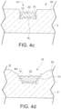
- Fig. 4c is a schematic partial side cross sectional diagram illustrating a gettering structure that may be used in the Fig. 3 and/or Fig. 5-15 VIG unit 1 according to an example embodiment of this invention.
- the base or bottom wall, and the sidewall(s), of getter recess 14 defined in the glass 2 are roughened 15 (e.g., by grinding and/or etching the glass substrate in recess 14) to allow the deposited EG to have more exposed surface area before and/or after activating/flashing. The result is more active gettering surface following activating/flashing of the EG 32.
- the gettering structure of Fig. 4c allows more undesirable gases to be absorbed in terms of volume and/or time by the EG following activation/flashing, compared to the gettering structure of Fig. 3 .
- the recess 14 in Fig. 4c can be formed by drilling a recess as shown in Fig.
- any of the recesses 14' in glass substrate 3 may also be shaped and/or provided with roughness 15 as in Fig. 4c , except that no EG is present in 14' prior to EG getter activation.
- Fig. 4d is similar to a combination of the embodiments of Figs. 4a and 4c described above, and is a schematic partial side cross sectional diagram illustrating a gettering structure that may be used in the Fig. 3 and/or Fig. 5-15 VIG unit 1 according to yet another example embodiment of this invention.
- the base or bottom wall, and the angled non-vertical sidewall(s), of getter recess 14 defined in the glass 2 are roughened 15 (e.g., by grinding and/or etching the glass substrate in recess 14) to allow the deposited EG to have more exposed surface area before and/or after activating/flashing.
- the recess 14 in Fig. 4d can be formed by drilling a recess as shown in Fig. 3 , rounding/chamfering as explained above in connection with Fig. 4a , and then roughening the bottom and sidewall glass surfaces of the recess via grinding with a grinding wheel, sandblasting, and/or etching via wet glass etchant, until the roughened structure 15 shown in Fig. 4d is achieved.
- the roughened bottom and sidewall surface 15 of the recess 14 in Fig. 4d is substantially rougher than is the major interior surface 2a of glass substrate 2.
- the gettering structure of Fig. 4d may or may not be used in combination with the gettering structure(s) of any of Figs. 4a-4c .
- any of the recesses 14' in glass substrate 3 e.g., see Figs. 5 , 7-8 , 10-11 , 13-15
- Fig. 4e is a schematic partial side cross sectional diagram illustrating a gettering structure that may be used in the Fig. 3 and/or Fig. 5-15 VIG unit 1 according to an example not falling in the scope of the appended claims.
- At least the base or bottom wall of getter recess 14 defined in the glass 2 is roughened by pre-depositing rough coating 36 thereon to allow the deposited EG to have more exposed surface area before and/or after activating/flashing.
- a rough (e.g., nodular) and/or porous coating 36 such as via sol gel or selected frit application, in order to promote porosity in the getter deposit 32 which increases the getter's sorption capacity before and/or after activating/flashing.
- the result is more active gettering surface following activating/flashing of the EG 32.
- the roughening of at least the base of the recess 14 in Fig. 4e via the rough coating 36 that supports the EG 32 allows the getter material from EG 32 to realize more active gettering surface compared to when the simple cylindrical getter recess with flat base is provided as shown in Fig. 3 .
- the gettering structure of Fig. 4e allows more undesirable gases to be absorbed in terms of volume and/or time by the EG following activation/flashing, compared to the gettering structure of Fig. 3 .
- the bottom surface of the recess 14 (i.e., the upper surface of the coating 36) in Fig. 4e is substantially rougher than is the major interior surface 2a of glass substrate 2.
- the gettering structure of Fig. 4e may or may not be used in combination with the gettering structure of any of Figs. 4a-4d .
- any of the recesses 14' in glass substrate 3 e.g., see Figs. 5 , 7-8 , 10-11 , 13-15 ) may also be provided with such a rough/porous coating 36, noting that no EG is present in recess 14' prior to EG getter activation.
- Fig. 4f is a combination of the embodiments of Figs. 4a and 4e described above, and is a schematic partial side cross sectional diagram illustrating a gettering structure that may be used in the Fig. 3 and/or Fig. 5-15 VIG unit 1 according to yet another example not falling in the scope of the appended claims.
- At least the base or bottom wall of getter recess 14 defined in the glass 2 is roughened by pre-depositing rough coating 36 thereon to allow the deposited EG to have more exposed surface area before and/or after activating/flashing.
- the sidewalls of the recess are also rounded/chamfered, to allow the EG to scatter further during activating/flashing.
- the bottom surface of the recess 14 i.e., the upper surface of the coating 36 in Fig. 4f is substantially rougher than is the major interior surface 2a of glass substrate 2.
- any surface of any of the recesses 14' in glass substrate 3 e.g., see Figs. 5 , 7-8 , 10-11 , 13-15 ) may also be provided with such a rough/porous coating 36.
- Figs. 4a-4f and Figs. 4j-4k )
- the EG 32 may be provided in a container that encompasses at least part of the getter material prior to and/or after deposition and/or activating.
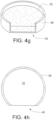
- Fig. 4g illustrates an embodiment where the EG 32 is provided within a getter container (e.g., metallic container) 32.
- Fig. 4h which is a top view of Fig.
- the container 38 is substantially C-shaped as viewed from above so as to have open side/end 40 where the getter material is more exposed.
- Such a structure is advantageous for VIG applications because the open side/end 40 of the getter container allows the scattering direction of getter material during activating/flashing to be controlled in particular direction(s) within the low pressure cavity 6 of the VIG unit 1.
- the evaporating flux is broadened with this shaped container, where the substantial C-shaped cross section produces a substantially radial evaporated flux during flashing/activating.
- the getter container 38 of Figs. 4g-4h can be positioned within a getter recess 14 and/or on a substrate 2 in any of Figs.
- the open side 40 of the container is particularly designed to face in any desired direction, such as in a direction away from or substantially parallel to the closest edge seal 4.
- the open end 40 allows more getter material to scatter outwardly during activating/flashing so that more active getter material from the EG densifies on the sidewall(s) of the getter recess 14 and/or on adjacent surfaces inside the cavity 6.
- Fig. 4i is similar to the embodiment of Fig. 4g-4h described above, except that the container 38 in the Fig. 4i embodiment has two open sides 40. This allows still further active getter material to scatter outwardly during activating/flashing so that more active getter material from the EG densifies on the sidewall(s) of the getter recess 14 and/or on adjacent surfaces inside the cavity 6.
- the example containers, or any other shaped container, may be used in any of the embodiments of Figs. 5-15 .
- Fig. 4j is a schematic partial side cross sectional diagram illustrating a gettering structure that may be used in the Fig. 3 and/or Fig. 5-15 VIG unit 1 according to another example not falling in the scope of the appended claims.
- the getter recess 14 is double drilled (using a first and second drill bits of different sizes) so that the recess has a stepped structure which allows evaporating getter material to scatter more widely (see arrows 44) during getter activating/flashing, so as to result in more active gettering surface following activating/flashing of the EG 32.
- the gettering structure of Fig. 4j allows the getter material from EG 32 to scatter more widely and further during activating/flashing, so that the result is more active gettering surface compared to when the simple cylindrical getter recess is provided as shown in Fig. 3 .
- the gettering structure of Fig. 4j allows more undesirable gases to be absorbed in terms of volume and/or time by the EG following activation/flashing, compared to the gettering structure of Fig. 3 .
- the Fig. 4k embodiment is the same as the Fig. 4a embodiment, except that the sidewalls are substantially flat instead of being rounded/curved.
- the Fig. 4 embodiment may be made and is advantageous for the reasons explained above in connection with Fig. 4a .
- any of the recesses 14' in glass substrate 3 e.g., see Figs. 5 , 7-8 , 10-11 , 13-15 ) may be shaped like recess 14 in Fig. 4j or Fig. 4k , noting that no EG is present in recess 14' prior to EG getter activation.
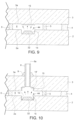
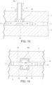
- Figs. 5-11 and 13-15 illustrate examples where, optionally in addition to the getter recess 14 in substrate 2 shown in Fig. 3 , there is provided a getter recess 14' in/on the glass substrate 3 opposite the original getter 32 location so as to be across the low pressure cavity 6 from the original getter location so as to increase the area of active gettering surface on the opposite substrate following EG activation/flashing and movement 44 of EG material from substrate 2 toward and onto substrate 3 during and/or as a result of activation/flashing.
- the getter 32 on substrate 2 When the getter 32 on substrate 2 is activated, evaporation causes getter material to deposit on the opposite substrate 3 across the cavity proximate to the original getter location, and the provision of recess 14' in that area of substrate 3 results in additional getter material surface area being formed on the opposing substrate 3 following activation/flashing.
- the recess 14' in substrate 3 located opposite the original getter 32 location is provided with roughened surface area at a sidewall of the recess 14'.
- Figs. 7 , 10 , and 13 show that the base and sidewall(s) of recess 14' in substrate 3 are roughened and/or provided with a rough surface 15, which rough surface 15 is more rough than the interior major surface 3a of substrate 3.
- the recess 14' in substrate 3 located opposite the original getter 32 location may or may not be provided with rough and/or porous coating 36 (possibly in addition to the roughened glass surface 15).
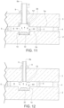
- Figs. 8 , 11 , and 14-15 show that the base and/or sidewall(s) of recess 14' in substrate 3 may be provided with rough and/or porous coating 36 which is more rough than the interior major surface 3a of substrate 3.
- Figs. 8 , 11 , and 14-15 show that the base and/or sidewall(s) of recess 14' in substrate 3 may be provided with rough and/or porous coating 36 which is more rough than the interior major surface 3a of substrate 3.
- the pump-out tube 8 may be provided in recess 14', with the interior of the tube 8 providing still further surface area upon which the getter material may depositing due to activation/flashing.
- the interior of the tube 8 providing still further surface area upon which the getter material may depositing due to activation/flashing.
- Figs. 6 , 9 and 12 illustrate that the surface of the substrate 3 opposite the original EG 32 location can be roughened, via a coating 36 and/or via roughening the glass, so as to provided increased surface area for the activated EG to deposit due to activation/flashing.
- the EG 32 is originally located in a recess 14 in/on substrate 2 (e.g., see Figs. 3 and 7-12 ), the EG 32 need not be originally located in a recess.
- the EG 32 is originally located on the major interior surface 2a of glass substrate 2 and not in a recess.
- a recess 14' and/or roughening is/are provided on the other substrate 3 opposite the EG location in order to provided additional surface area for active EG material to deposit due to activation/flashing.
- any of the getter structures of Figs. 4a-4k may be used for the getter structure/recess 14 in the Fig. 5 embodiment (or for any of the embodiments of Figs. 7-12 ).
- the recesses 14 and/or 14' in Figs. 5-15 may or may not be cylindrical in shape in certain instances, any of the getter structures of Figs. 4a-4f or 4j-4k (absent the original getter material prior to activation) may be used for the getter structure/recess 14' on the opposite substrate 3 in any of the embodiments of Figs. 5-15 .
- Fig. 6 illustrates an example not falling in the scope of the appended claims, where, in addition the getter recess 14 shown in Fig. 3 , there is provided an additional roughened and/or porous coating 36 on the substrate 3 opposite the original getter 32 location so as to be across the low pressure cavity 6 from the original getter location so as to increase the area of active gettering surface on the opposite substrate following EG activation/flashing.
- any of the getter structures of Figs. 4a-4k may be used for the getter structure/recess 14 in the Fig. 6 embodiment, and likewise any of the getter structures of Figs. 4e-4f (absent the original getter material prior to activation) may be used for or in the coating area 36 on the opposite substrate 3 in the Fig. 6 example.
- the getter recess 14 and/or getter container 38 in the getter recess is/are shaped to increase evaporated getter material surface area, with evaporated getter material being the getter material that is present (e.g., present in/on one or more of: getter recess sidewall(s), getter recess, interior major surface(s) of one or both substrates proximate the getter recess, and/or pump-out tube recess and/or tube itself) following activation and/or flashing of getter that included EG type material.
- the getter structure (14', 15 and/or 36) on the opposite substrate 3 is shaped/designed to increase evaporated getter material surface area following getter activation.
- Fig. 16 illustrates the VIG window unit of the Fig. 7 embodiment after activating/flashing of the getter 32.
- Fig. 16 illustrates that, after activating/flashing the EG getter 32, the evaporated and deposited EG material 32b' from the getter 32 is present on both the opposing substrate 3 proximate the original getter recess 14 and possibly on sidewall(s) at 15 of the original getter recess 14.
- the EG material 32b' following activation may be deposited on surfaces of the recess 14' and/or on the major interior surface 3a of substrate 3 proximate the original getter recess 14. It is also possible that activated EG material 32b' may end up deposited on part of the major interior surface 2a of the substrate 2 proximate the original getter recess 14.
- an EG getter 32 prior to activating, an EG getter 32 is located on substrate 2 in recess 14, whereas after activating evaporated and deposited getter material 32b' from the EG material may be located (i) on the second substrate 3 at least in an area substantially opposite the recess 14 defined in the first substrate 2, and/or (ii) on sidewall(s) of recess 14.
- Fig. 16 shows how EG getter material evaporates and moves during activation; and when EG getter material is used in other embodiments of this invention the evaporated material moves in a similar manner so as to end up deposited on at least the opposing substrate 3 after activation/flashing. Still referring to Fig. 16 , while not illustrated, evaporated and deposited getter material 32b' from an EG originally located in getter container 38 may also end up, following activation, in and/or on portions of the container 38.
Landscapes
- Engineering & Computer Science (AREA)
- Structural Engineering (AREA)
- Civil Engineering (AREA)
- Architecture (AREA)
- Joining Of Glass To Other Materials (AREA)
- Securing Of Glass Panes Or The Like (AREA)
- Physics & Mathematics (AREA)
- Nonlinear Science (AREA)
- Mathematical Physics (AREA)
- Chemical & Material Sciences (AREA)
- Crystallography & Structural Chemistry (AREA)
- General Physics & Mathematics (AREA)
- Optics & Photonics (AREA)
Claims (12)
- Fenstereinheit (1) aus vakuumisoliertem Glas (VIG), umfassend:erste und zweite im Wesentlichen parallele Substrate (2, 3), die jeweils Glas umfassen,eine Vielzahl von Abstandshaltern (5) und eine Dichtung (4), die zwischen dem ersten und zweiten Substrat (2, 3) bereitgestellt sind,einen Raum (6), mindestens durch die Dichtung (4) definiert, der sich zwischen dem ersten und dem zweiten Substrat (2, 3) befindet und einen Druck aufweist, der geringer als atmosphärischer Druck ist,eine in dem ersten Substrat (2) definierte Getteraussparung (14) zum Aufnehmen eines ursprünglich positionierten Getters (32) undeine Getterstruktur (14'; 15; 36) auf dem zweiten Substrat (3), die sich im Wesentlichen gegenüber der Getteraussparung (14) im ersten Substrat (2) befindet, wobei die Getterstruktur (14'; 15; 36), die sich auf dem zweiten Substrat (3) befindet, dazu gestaltet ist, eine auf dem zweiten Substrat (3) bereitgestellte Oberfläche des Gettermaterials nach einer Getteraktivierung zu vergrößern, dadurch gekennzeichnet, dassdie Getterstruktur (14'; 15; 36) auf dem zweiten Substrat umfassteine Aussparung (14'), die eine Basis und mindestens eine Seitenwand in dem zweiten Substrat (3) definiert aufweist, und wobeidie mindestens eine Seitenwand der Aussparung (14') aufgeraut und/oder mit einer rauen Oberfläche, die rauer als die innere Hauptoberfläche (3a) des zweiten Substrats (3) ist, bereitgestellt ist.
- VIG-Fenstereinheit nach Anspruch 1, wobei sich die mindestens eine Seitenwand zwischen der Basis und einer Hauptinnenoberfläche des zweiten Substrats (3) erstreckt, wobei vorzugsweise die Basis der in dem zweiten Substrat (3) definierten Aussparung (14') eine aufgeraute Oberfläche (15) umfasst, die rauer als eine Hauptinnenoberfläche des zweiten Substrats ist.
- VIG-Fenstereinheit nach Anspruch 2, wobei die Seitenwand der in dem zweiten Substrat (3) definierten Aussparung (14') mindestens teilweise relativ zur Vertikalen abgewinkelt ist.
- VIG-Fenstereinheit nach einem der Ansprüche 2-3, wobei sich direkt über und/oder in der in dem zweiten Substrat definierten Aussparung (14, 14') ein Abpumprohr (8) befindet.
- VIG-Fenstereinheit nach einem vorstehenden Anspruch, wobei die Getterstruktur (14') auf dem zweiten Substrat (3) eine raue und/oder poröse Beschichtung (36) auf dem zweiten Substrat (3), an einer Stelle gegenüber der in dem ersten Substrat (2) definierten Getteraussparung (14) umfasst.
- VIG-Fenstereinheit nach einem vorstehenden Anspruch, wobei das Gettermaterial Barium umfasst.
- Fenstereinheit (1) aus vakuumisoliertem Glas (VIG), umfassend:erste und zweite im Wesentlichen parallele Substrate (2, 3), die Glas umfassen,eine Vielzahl von Abstandshaltern (5) und eine Dichtung (4), die zwischen dem ersten und zweiten Substrat (2, 3) bereitgestellt sind,einen Raum (6), mindestens durch die Dichtung (4) definiert, der sich zwischen dem ersten und dem zweiten Substrat (2, 3) befindet und einen Druck aufweist, der geringer als atmosphärischer Druck ist,Gettermaterial von einem verdampfbaren Getter (32), der sich in und/oder nahe einer Getteraussparung (14) befindet, die in dem ersten Substrat (2) definiert ist,wobei die Getteraussparung (14) mindestens eine aufgeraute Oberfläche (15; 36) umfasst, um die Oberfläche des Gettermaterials zu vergrößern, dadurch gekennzeichnet, dass die Getteraussparung (14) eine Basis und mindestens eine Seitenwand aufweist, undwobei die mindestens eine Seitenwand der Getteraussparung (14) aufgeraut ist und rauer als eine Hauptinnenoberfläche des ersten Substrats ist, in dem die Getteraussparung definiert ist.
- VIG-Fenstereinheit nach Anspruch 7, wobei die Getteraussparung (14) eine Bodenoberfläche und mindestens eine Seitenwand, die mindestens teilweise relativ zur Vertikalen abgewinkelt ist, beinhaltet.
- VIG-Fenstereinheit nach einem der Ansprüche 7-8, wobei sich mindestens ein Teil des Gettermaterials in einem Getterbehälter (38) befindet, der eine Behälterseitenwand umfasst und in der Getteraussparung (14) bereitgestellt ist, wobei der Getterbehälter (38) vorzugsweise mindestens eine offene Seite und/oder ein Ende beinhaltet, wo die Behälterseitenwand nicht vorhanden ist oder von oben betrachtet verkleinert ist.
- Fenstereinheit (1) aus vakuumisoliertem Glas (VIG) nach Anspruch 7,
wobei die Getteraussparung (14) mindestens eine raue Beschichtung (36) umfasst, die so darin bereitgestellt ist, dass sie sich zwischen dem Gettermaterial (32) und dem ersten Substrat befindet. - VIG-Fenstereinheit nach Anspruch 10, wobei das Gettermaterial Barium umfasst.
- Fenstereinheit (1) aus vakuumisoliertem Glas (VIG) nach Anspruch 1, wobei der ursprünglich positionierte Getter ein ursprünglich positionierter verdampfbarer Getter (EG) ist, und
wobei sich verdampftes und abgeschiedenes Gettermaterial aus dem EG sowohl in der Getteraussparung (14) als auch in der Getterstruktur (14') befindet.
Applications Claiming Priority (2)
| Application Number | Priority Date | Filing Date | Title |
|---|---|---|---|
| US13/562,386 US9388628B2 (en) | 2012-07-31 | 2012-07-31 | Vacuum insulated glass (VIG) window unit with getter structure and method of making same |
| PCT/US2013/051023 WO2014022106A1 (en) | 2012-07-31 | 2013-07-18 | Vacuum insulated glass (vig) window unit with getter structure and method of making same |
Publications (2)
| Publication Number | Publication Date |
|---|---|
| EP2880236A1 EP2880236A1 (de) | 2015-06-10 |
| EP2880236B1 true EP2880236B1 (de) | 2024-05-29 |
Family
ID=48901190
Family Applications (1)
| Application Number | Title | Priority Date | Filing Date |
|---|---|---|---|
| EP13742574.0A Active EP2880236B1 (de) | 2012-07-31 | 2013-07-18 | Fenstereinheit aus vakuumisoliertem glas mit einer fängerstruktur und verfahren zur herstellung davon |
Country Status (8)
| Country | Link |
|---|---|
| US (2) | US9388628B2 (de) |
| EP (1) | EP2880236B1 (de) |
| JP (1) | JP6456824B2 (de) |
| KR (1) | KR102110926B1 (de) |
| CN (2) | CN104718341A (de) |
| DK (1) | DK2880236T3 (de) |
| PL (1) | PL2880236T3 (de) |
| WO (1) | WO2014022106A1 (de) |
Families Citing this family (29)
| Publication number | Priority date | Publication date | Assignee | Title |
|---|---|---|---|---|
| US9388628B2 (en) | 2012-07-31 | 2016-07-12 | Guardian Industries Corp. | Vacuum insulated glass (VIG) window unit with getter structure and method of making same |
| EP2973685B1 (de) * | 2013-03-13 | 2018-01-17 | Robert Bosch GmbH | Mems-vorrichtung mit einem getter |
| US9637378B2 (en) | 2013-09-11 | 2017-05-02 | Taiwan Semiconductor Manufacturing Co., Ltd. | Cup-like getter scheme |
| US9242853B2 (en) | 2013-10-15 | 2016-01-26 | Taiwan Semiconductor Manufacturing Co., Ltd. | Method of improving getter efficiency by increasing superficial area |
| FR3014240B1 (fr) * | 2013-11-29 | 2017-05-05 | Commissariat Energie Atomique | Procede de realisation d'un substrat comportant un materiau getter dispose sur des parois d'un ou plusieurs trous borgnes formes dans le substrat |
| US9784027B2 (en) | 2013-12-31 | 2017-10-10 | Guardian Glass, LLC | Vacuum insulating glass (VIG) unit with metallic peripheral edge seal and/or methods of making the same |
| US10012019B2 (en) | 2013-12-31 | 2018-07-03 | Guardian Glass, LLC | Vacuum insulating glass (VIG) unit with metallic peripheral edge seal and/or methods of making the same |
| US10280680B2 (en) | 2013-12-31 | 2019-05-07 | Guardian Glass, LLC | Vacuum insulating glass (VIG) unit with pump-out port sealed using metal solder seal, and/or method of making the same |
| US10378272B2 (en) | 2014-09-30 | 2019-08-13 | Panasonic Intellectual Property Management Co., Ltd. | Glass panel unit, temporary assembly of glass panel unit, completed assembly of glass panel unit, method for manufacturing glass panel unit |
| KR102662193B1 (ko) | 2015-07-01 | 2024-05-02 | 가디언 글라스, 엘엘씨 | 금속성 주변 에지 실을 구비한 진공 단열 유리(vig) 유닛 및/또는 그 제조 방법 |
| US10145005B2 (en) | 2015-08-19 | 2018-12-04 | Guardian Glass, LLC | Techniques for low temperature direct graphene growth on glass |
| US10253550B1 (en) | 2015-10-30 | 2019-04-09 | Corning Incorporated | Vacuum insulated glass units and methodology for manufacturing the same |
| EP3483127B1 (de) * | 2016-07-06 | 2022-03-02 | Je Il Park | Verfahren zur herstellung einer vakuumisolierglasscheibe und vorrichtung zum verschliessen einer verschlusskappe |
| EP3548687A1 (de) | 2016-12-01 | 2019-10-09 | Mechem Lab Ltd. | Aktivierungsfreie getter und verfahren zu deren installation in eine vakuumisolierte verglasung |
| JP6991238B2 (ja) * | 2017-11-10 | 2022-01-12 | 日本板硝子株式会社 | ガラスパネル |
| WO2019208003A1 (ja) * | 2018-04-26 | 2019-10-31 | パナソニックIpマネジメント株式会社 | ガラスパネルユニット、及びガラスパネルユニットの製造方法 |
| JPWO2019208017A1 (ja) * | 2018-04-27 | 2021-05-13 | パナソニックIpマネジメント株式会社 | ガラスパネルユニット及びガラス窓 |
| US10822270B2 (en) | 2018-08-01 | 2020-11-03 | Guardian Glass, LLC | Coated article including ultra-fast laser treated silver-inclusive layer in low-emissivity thin film coating, and/or method of making the same |
| US12098587B2 (en) * | 2018-10-12 | 2024-09-24 | Panasonic Intellectual Property Management Co., Ltd. | Glass panel unit and glass window |
| US20200217125A1 (en) * | 2019-01-04 | 2020-07-09 | Guardian Glass, LLC | Internal tube for vacuum insulated glass (vig) unit evacuation and hermetic sealing, vig unit including internal tube, and associated methods |
| PL3990742T3 (pl) * | 2019-06-25 | 2025-03-03 | Vkr Holding A/S | Izolowana próżniowo szyba zespolona z getterem oraz sposób aktywowania gettera w izolowanej próżniowo szybie zespolonej |
| CN111116058A (zh) * | 2019-12-24 | 2020-05-08 | 江苏凯尚新材料研究院有限公司 | 钢化无嘴无孔真空玻璃及其批量合成的制造方法 |
| KR20220059303A (ko) * | 2020-11-02 | 2022-05-10 | 엘지전자 주식회사 | 진공단열체 |
| FR3122689B1 (fr) * | 2021-05-07 | 2024-01-19 | Saint Gobain | Dispositifs perforés et vitrages les comprenant |
| US12410654B2 (en) | 2022-11-23 | 2025-09-09 | LuxWall, Inc. | Vacuum insulated panel with passivation layer |
| US20240167318A1 (en) | 2022-11-23 | 2024-05-23 | LuxWall, Inc. | Vacuum insulated panel with optimized compressive and/or tensile stress in glass |
| EP4577717B1 (de) | 2022-11-23 | 2025-09-17 | Luxwall, Inc. | Vakuumisolierte platte mit keramischen abstandshaltern |
| US12612821B2 (en) | 2024-04-16 | 2026-04-28 | LuxWall, Inc. | Vacuum insulated panel with improved thermal performance proximate edge of glass during asymmetric thermal conditions |
| US20250354431A1 (en) * | 2024-05-15 | 2025-11-20 | LuxWall, Inc. | Vacuum insulated panel with trough for getter |
Citations (1)
| Publication number | Priority date | Publication date | Assignee | Title |
|---|---|---|---|---|
| CN102544150A (zh) * | 2011-12-30 | 2012-07-04 | 扬州大学 | 带有光电转化层的真空玻璃 |
Family Cites Families (35)
| Publication number | Priority date | Publication date | Assignee | Title |
|---|---|---|---|---|
| JPS4882363A (de) * | 1972-02-04 | 1973-11-02 | ||
| EP0061655B2 (de) * | 1981-03-31 | 1990-03-28 | Hans Sauer | Von der Umgebung abgedichtete Schaltkammer für elektrische Kontakte |
| JPS6055060U (ja) * | 1983-09-26 | 1985-04-17 | 鹿児島日本電気株式会社 | 螢光表示管 |
| US5657607A (en) | 1989-08-23 | 1997-08-19 | University Of Sydney | Thermally insulating glass panel and method of construction |
| JPH051153U (ja) * | 1991-06-21 | 1993-01-08 | 鹿児島日本電気株式会社 | 蛍光表示管 |
| CA2127265C (en) | 1992-01-31 | 2002-10-08 | Richard Edward Collins | Improvements to thermally insulating glass panels |
| CN1078659C (zh) | 1993-06-30 | 2002-01-30 | 悉尼大学 | 制造真空玻璃窗的方法 |
| JPH07140906A (ja) * | 1993-11-15 | 1995-06-02 | Canon Inc | 画像表示装置 |
| IT1277457B1 (it) | 1995-08-07 | 1997-11-10 | Getters Spa | Combinazione di materiali getter e dispositivo relativo |
| HU226464B1 (en) | 1996-02-09 | 2008-12-29 | Getters Spa | Combination of materials for the low temperature triggering of the activation of getter materials and getter devices containing the same |
| BR0005255A (pt) | 1999-03-05 | 2001-01-09 | Uni Charm Corp | Folha composta e método de fabricação da mesma |
| AUPQ230499A0 (en) * | 1999-08-18 | 1999-09-09 | University Of Sydney, The | Evacuated glass panel with getter and method of construction thereof |
| US6422824B1 (en) | 1999-09-15 | 2002-07-23 | Industrial Technology Research Institute | Getting assembly for vacuum display panels |
| US6558494B1 (en) | 1999-09-24 | 2003-05-06 | Guardian Industries Corp. | Vacuum IG window unit with edge seal at least partially diffused at temper and completed via microwave curing, and corresponding method of making the same |
| US6383580B1 (en) | 1999-11-12 | 2002-05-07 | Guardian Industries Corp. | Vacuum IG window unit with edge mounted pump-out tube |
| US6497931B1 (en) * | 2000-01-11 | 2002-12-24 | Guardian Industries Corp. | Vacuum IG unit with colored spacers |
| KR100415615B1 (ko) | 2001-06-13 | 2004-01-24 | 엘지전자 주식회사 | 게터 조성물 및 이를 이용한 전계방출표시소자 |
| ITMI20011341A1 (it) | 2001-06-26 | 2002-12-26 | Getters Spa | Dispositivo getter evaporabile per tubi a raggi catodici |
| US6692600B2 (en) | 2001-09-14 | 2004-02-17 | Guardian Industries Corp. | VIG evacuation with plasma excitation |
| JP2003137612A (ja) | 2001-10-25 | 2003-05-14 | Nippon Sheet Glass Co Ltd | ガラスパネルとその製法 |
| CN2522579Y (zh) * | 2001-12-07 | 2002-11-27 | 唐健正 | 带吸气剂的真空玻璃 |
| JP2003192399A (ja) * | 2001-12-25 | 2003-07-09 | Nippon Sheet Glass Co Ltd | ガラスパネル吸引孔用蓋体とその蓋体の使用方法 |
| JP2003212610A (ja) * | 2002-01-25 | 2003-07-30 | Nippon Sheet Glass Co Ltd | ガラスパネルのゲッター加熱方法とその加熱装置 |
| US7476426B2 (en) * | 2002-09-05 | 2009-01-13 | Boe Technology Group Co., Ltd. | Evacuated glass panel having degassing device |
| JP2004149343A (ja) | 2002-10-29 | 2004-05-27 | Nippon Sheet Glass Co Ltd | ガラスパネル |
| JP2004152530A (ja) | 2002-10-29 | 2004-05-27 | Nippon Sheet Glass Co Ltd | ガラスパネルの製法とその製法によるガラスパネル |
| JP2005139055A (ja) * | 2003-11-10 | 2005-06-02 | Nippon Sheet Glass Co Ltd | ガラスパネルの製造方法及びその製造方法により製造されたガラスパネル |
| CN2890046Y (zh) * | 2006-02-20 | 2007-04-18 | 何世廉 | 内置吸气剂的真空玻璃 |
| CN101074147A (zh) * | 2006-05-18 | 2007-11-21 | 陈靓 | 一种真空平板玻璃的制造方法 |
| US8137494B2 (en) * | 2007-12-14 | 2012-03-20 | Guardian Industries Corp. | Vacuum insulating glass unit with large pump-out port, and/or method of making the same |
| CN101560864B (zh) * | 2008-04-14 | 2011-11-09 | 福建钧石能源有限公司 | 光伏真空窗户及其制造方法 |
| US8227055B2 (en) | 2009-05-01 | 2012-07-24 | Guardian Industries Corp. | Vacuum insulating glass unit including infrared meltable glass frit, and/or method of making the same |
| JP2011204594A (ja) | 2010-03-26 | 2011-10-13 | Canon Inc | 電界放出ディスプレイ用の非蒸発型ゲッター |
| CN202099205U (zh) * | 2011-06-03 | 2012-01-04 | 洛阳兰迪玻璃机器有限公司 | 一种带有环形吸气剂容置槽的真空玻璃 |
| US9388628B2 (en) | 2012-07-31 | 2016-07-12 | Guardian Industries Corp. | Vacuum insulated glass (VIG) window unit with getter structure and method of making same |
-
2012
- 2012-07-31 US US13/562,386 patent/US9388628B2/en active Active
-
2013
- 2013-07-18 DK DK13742574.0T patent/DK2880236T3/da active
- 2013-07-18 CN CN201380050473.6A patent/CN104718341A/zh active Pending
- 2013-07-18 WO PCT/US2013/051023 patent/WO2014022106A1/en not_active Ceased
- 2013-07-18 JP JP2015525444A patent/JP6456824B2/ja active Active
- 2013-07-18 EP EP13742574.0A patent/EP2880236B1/de active Active
- 2013-07-18 CN CN201910152644.5A patent/CN110094146A/zh active Pending
- 2013-07-18 KR KR1020157003848A patent/KR102110926B1/ko active Active
- 2013-07-18 PL PL13742574.0T patent/PL2880236T3/pl unknown
-
2016
- 2016-07-07 US US15/203,993 patent/US10458176B2/en active Active
Patent Citations (1)
| Publication number | Priority date | Publication date | Assignee | Title |
|---|---|---|---|---|
| CN102544150A (zh) * | 2011-12-30 | 2012-07-04 | 扬州大学 | 带有光电转化层的真空玻璃 |
Also Published As
| Publication number | Publication date |
|---|---|
| JP6456824B2 (ja) | 2019-01-23 |
| DK2880236T3 (da) | 2024-06-24 |
| US9388628B2 (en) | 2016-07-12 |
| WO2014022106A1 (en) | 2014-02-06 |
| US20160319587A1 (en) | 2016-11-03 |
| US20140037869A1 (en) | 2014-02-06 |
| CN110094146A (zh) | 2019-08-06 |
| KR102110926B1 (ko) | 2020-05-14 |
| EP2880236A1 (de) | 2015-06-10 |
| KR20150038069A (ko) | 2015-04-08 |
| PL2880236T3 (pl) | 2024-07-29 |
| JP2015529622A (ja) | 2015-10-08 |
| CN104718341A (zh) | 2015-06-17 |
| US10458176B2 (en) | 2019-10-29 |
Similar Documents
| Publication | Publication Date | Title |
|---|---|---|
| EP2880236B1 (de) | Fenstereinheit aus vakuumisoliertem glas mit einer fängerstruktur und verfahren zur herstellung davon | |
| US9416581B2 (en) | Vacuum insulated glass (VIG) window unit including hybrid getter and making same | |
| US10427395B2 (en) | Method of making vacuum insulated glass (VIG) window unit including activating getter | |
| US6420002B1 (en) | Vacuum IG unit with spacer/pillar getter | |
| US6635321B2 (en) | Vacuum IG window unit with edge seal formed via microwave curing, and corresponding method of making the same | |
| CA3050155A1 (en) | Vacuum glass and preparation process therefor | |
| WO2005077855A1 (ja) | ガラスパネルの製造方法、及びその製造方法により製造されたガラスパネル | |
| WO2004039741A1 (ja) | ガラスパネル | |
| WO2004039742A1 (ja) | ガラスパネルの製法とその製法によるガラスパネル | |
| WO2002050394A1 (en) | Evacuated thermoinsulating glass panel and process for the manufacture thereof | |
| JP2000044291A (ja) | 低圧複層ガラスおよびその製造方法 |
Legal Events
| Date | Code | Title | Description |
|---|---|---|---|
| PUAI | Public reference made under article 153(3) epc to a published international application that has entered the european phase |
Free format text: ORIGINAL CODE: 0009012 |
|
| 17P | Request for examination filed |
Effective date: 20150219 |
|
| AK | Designated contracting states |
Kind code of ref document: A1 Designated state(s): AL AT BE BG CH CY CZ DE DK EE ES FI FR GB GR HR HU IE IS IT LI LT LU LV MC MK MT NL NO PL PT RO RS SE SI SK SM TR |
|
| AX | Request for extension of the european patent |
Extension state: BA ME |
|
| RIN1 | Information on inventor provided before grant (corrected) |
Inventor name: PETRMICHL, RUDOLPH, H. Inventor name: HOGAN, JOHN, P. |
|
| DAX | Request for extension of the european patent (deleted) | ||
| RAP1 | Party data changed (applicant data changed or rights of an application transferred) |
Owner name: GUARDIAN GLASS, LLC |
|
| STAA | Information on the status of an ep patent application or granted ep patent |
Free format text: STATUS: EXAMINATION IS IN PROGRESS |
|
| 17Q | First examination report despatched |
Effective date: 20210528 |
|
| GRAP | Despatch of communication of intention to grant a patent |
Free format text: ORIGINAL CODE: EPIDOSNIGR1 |
|
| STAA | Information on the status of an ep patent application or granted ep patent |
Free format text: STATUS: GRANT OF PATENT IS INTENDED |
|
| INTG | Intention to grant announced |
Effective date: 20240226 |
|
| GRAS | Grant fee paid |
Free format text: ORIGINAL CODE: EPIDOSNIGR3 |
|
| GRAA | (expected) grant |
Free format text: ORIGINAL CODE: 0009210 |
|
| STAA | Information on the status of an ep patent application or granted ep patent |
Free format text: STATUS: THE PATENT HAS BEEN GRANTED |
|
| AK | Designated contracting states |
Kind code of ref document: B1 Designated state(s): AL AT BE BG CH CY CZ DE DK EE ES FI FR GB GR HR HU IE IS IT LI LT LU LV MC MK MT NL NO PL PT RO RS SE SI SK SM TR |
|
| REG | Reference to a national code |
Ref country code: GB Ref legal event code: FG4D |
|
| REG | Reference to a national code |
Ref country code: CH Ref legal event code: EP |
|
| REG | Reference to a national code |
Ref country code: IE Ref legal event code: FG4D |
|
| REG | Reference to a national code |
Ref country code: DE Ref legal event code: R096 Ref document number: 602013085752 Country of ref document: DE |
|
| REG | Reference to a national code |
Ref country code: DK Ref legal event code: T3 Effective date: 20240619 |
|
| REG | Reference to a national code |
Ref country code: LT Ref legal event code: MG9D |
|
| REG | Reference to a national code |
Ref country code: NL Ref legal event code: MP Effective date: 20240529 |
|
| PG25 | Lapsed in a contracting state [announced via postgrant information from national office to epo] |
Ref country code: IS Free format text: LAPSE BECAUSE OF FAILURE TO SUBMIT A TRANSLATION OF THE DESCRIPTION OR TO PAY THE FEE WITHIN THE PRESCRIBED TIME-LIMIT Effective date: 20240929 |
|
| PG25 | Lapsed in a contracting state [announced via postgrant information from national office to epo] |
Ref country code: BG Free format text: LAPSE BECAUSE OF FAILURE TO SUBMIT A TRANSLATION OF THE DESCRIPTION OR TO PAY THE FEE WITHIN THE PRESCRIBED TIME-LIMIT Effective date: 20240529 |
|
| PG25 | Lapsed in a contracting state [announced via postgrant information from national office to epo] |
Ref country code: FI Free format text: LAPSE BECAUSE OF FAILURE TO SUBMIT A TRANSLATION OF THE DESCRIPTION OR TO PAY THE FEE WITHIN THE PRESCRIBED TIME-LIMIT Effective date: 20240529 Ref country code: HR Free format text: LAPSE BECAUSE OF FAILURE TO SUBMIT A TRANSLATION OF THE DESCRIPTION OR TO PAY THE FEE WITHIN THE PRESCRIBED TIME-LIMIT Effective date: 20240529 |
|
| PG25 | Lapsed in a contracting state [announced via postgrant information from national office to epo] |
Ref country code: GR Free format text: LAPSE BECAUSE OF FAILURE TO SUBMIT A TRANSLATION OF THE DESCRIPTION OR TO PAY THE FEE WITHIN THE PRESCRIBED TIME-LIMIT Effective date: 20240830 |
|
| REG | Reference to a national code |
Ref country code: AT Ref legal event code: MK05 Ref document number: 1690778 Country of ref document: AT Kind code of ref document: T Effective date: 20240529 |
|
| PG25 | Lapsed in a contracting state [announced via postgrant information from national office to epo] |
Ref country code: ES Free format text: LAPSE BECAUSE OF FAILURE TO SUBMIT A TRANSLATION OF THE DESCRIPTION OR TO PAY THE FEE WITHIN THE PRESCRIBED TIME-LIMIT Effective date: 20240529 |
|
| PG25 | Lapsed in a contracting state [announced via postgrant information from national office to epo] |
Ref country code: AT Free format text: LAPSE BECAUSE OF FAILURE TO SUBMIT A TRANSLATION OF THE DESCRIPTION OR TO PAY THE FEE WITHIN THE PRESCRIBED TIME-LIMIT Effective date: 20240529 |
|
| PG25 | Lapsed in a contracting state [announced via postgrant information from national office to epo] |
Ref country code: LV Free format text: LAPSE BECAUSE OF FAILURE TO SUBMIT A TRANSLATION OF THE DESCRIPTION OR TO PAY THE FEE WITHIN THE PRESCRIBED TIME-LIMIT Effective date: 20240529 |
|
| PG25 | Lapsed in a contracting state [announced via postgrant information from national office to epo] |
Ref country code: NO Free format text: LAPSE BECAUSE OF FAILURE TO SUBMIT A TRANSLATION OF THE DESCRIPTION OR TO PAY THE FEE WITHIN THE PRESCRIBED TIME-LIMIT Effective date: 20240829 Ref country code: LV Free format text: LAPSE BECAUSE OF FAILURE TO SUBMIT A TRANSLATION OF THE DESCRIPTION OR TO PAY THE FEE WITHIN THE PRESCRIBED TIME-LIMIT Effective date: 20240529 Ref country code: IS Free format text: LAPSE BECAUSE OF FAILURE TO SUBMIT A TRANSLATION OF THE DESCRIPTION OR TO PAY THE FEE WITHIN THE PRESCRIBED TIME-LIMIT Effective date: 20240929 Ref country code: HR Free format text: LAPSE BECAUSE OF FAILURE TO SUBMIT A TRANSLATION OF THE DESCRIPTION OR TO PAY THE FEE WITHIN THE PRESCRIBED TIME-LIMIT Effective date: 20240529 Ref country code: GR Free format text: LAPSE BECAUSE OF FAILURE TO SUBMIT A TRANSLATION OF THE DESCRIPTION OR TO PAY THE FEE WITHIN THE PRESCRIBED TIME-LIMIT Effective date: 20240830 Ref country code: FI Free format text: LAPSE BECAUSE OF FAILURE TO SUBMIT A TRANSLATION OF THE DESCRIPTION OR TO PAY THE FEE WITHIN THE PRESCRIBED TIME-LIMIT Effective date: 20240529 Ref country code: ES Free format text: LAPSE BECAUSE OF FAILURE TO SUBMIT A TRANSLATION OF THE DESCRIPTION OR TO PAY THE FEE WITHIN THE PRESCRIBED TIME-LIMIT Effective date: 20240529 Ref country code: BG Free format text: LAPSE BECAUSE OF FAILURE TO SUBMIT A TRANSLATION OF THE DESCRIPTION OR TO PAY THE FEE WITHIN THE PRESCRIBED TIME-LIMIT Effective date: 20240529 Ref country code: AT Free format text: LAPSE BECAUSE OF FAILURE TO SUBMIT A TRANSLATION OF THE DESCRIPTION OR TO PAY THE FEE WITHIN THE PRESCRIBED TIME-LIMIT Effective date: 20240529 Ref country code: RS Free format text: LAPSE BECAUSE OF FAILURE TO SUBMIT A TRANSLATION OF THE DESCRIPTION OR TO PAY THE FEE WITHIN THE PRESCRIBED TIME-LIMIT Effective date: 20240829 |
|
| PG25 | Lapsed in a contracting state [announced via postgrant information from national office to epo] |
Ref country code: NL Free format text: LAPSE BECAUSE OF FAILURE TO SUBMIT A TRANSLATION OF THE DESCRIPTION OR TO PAY THE FEE WITHIN THE PRESCRIBED TIME-LIMIT Effective date: 20240529 |
|
| PG25 | Lapsed in a contracting state [announced via postgrant information from national office to epo] |
Ref country code: NL Free format text: LAPSE BECAUSE OF FAILURE TO SUBMIT A TRANSLATION OF THE DESCRIPTION OR TO PAY THE FEE WITHIN THE PRESCRIBED TIME-LIMIT Effective date: 20240529 |
|
| PG25 | Lapsed in a contracting state [announced via postgrant information from national office to epo] |
Ref country code: EE Free format text: LAPSE BECAUSE OF FAILURE TO SUBMIT A TRANSLATION OF THE DESCRIPTION OR TO PAY THE FEE WITHIN THE PRESCRIBED TIME-LIMIT Effective date: 20240529 |
|
| PG25 | Lapsed in a contracting state [announced via postgrant information from national office to epo] |
Ref country code: CZ Free format text: LAPSE BECAUSE OF FAILURE TO SUBMIT A TRANSLATION OF THE DESCRIPTION OR TO PAY THE FEE WITHIN THE PRESCRIBED TIME-LIMIT Effective date: 20240529 |
|
| PG25 | Lapsed in a contracting state [announced via postgrant information from national office to epo] |
Ref country code: SK Free format text: LAPSE BECAUSE OF FAILURE TO SUBMIT A TRANSLATION OF THE DESCRIPTION OR TO PAY THE FEE WITHIN THE PRESCRIBED TIME-LIMIT Effective date: 20240529 Ref country code: RO Free format text: LAPSE BECAUSE OF FAILURE TO SUBMIT A TRANSLATION OF THE DESCRIPTION OR TO PAY THE FEE WITHIN THE PRESCRIBED TIME-LIMIT Effective date: 20240529 |
|
| PG25 | Lapsed in a contracting state [announced via postgrant information from national office to epo] |
Ref country code: SM Free format text: LAPSE BECAUSE OF FAILURE TO SUBMIT A TRANSLATION OF THE DESCRIPTION OR TO PAY THE FEE WITHIN THE PRESCRIBED TIME-LIMIT Effective date: 20240529 |
|
| PG25 | Lapsed in a contracting state [announced via postgrant information from national office to epo] |
Ref country code: SM Free format text: LAPSE BECAUSE OF FAILURE TO SUBMIT A TRANSLATION OF THE DESCRIPTION OR TO PAY THE FEE WITHIN THE PRESCRIBED TIME-LIMIT Effective date: 20240529 Ref country code: SK Free format text: LAPSE BECAUSE OF FAILURE TO SUBMIT A TRANSLATION OF THE DESCRIPTION OR TO PAY THE FEE WITHIN THE PRESCRIBED TIME-LIMIT Effective date: 20240529 Ref country code: RO Free format text: LAPSE BECAUSE OF FAILURE TO SUBMIT A TRANSLATION OF THE DESCRIPTION OR TO PAY THE FEE WITHIN THE PRESCRIBED TIME-LIMIT Effective date: 20240529 Ref country code: EE Free format text: LAPSE BECAUSE OF FAILURE TO SUBMIT A TRANSLATION OF THE DESCRIPTION OR TO PAY THE FEE WITHIN THE PRESCRIBED TIME-LIMIT Effective date: 20240529 Ref country code: CZ Free format text: LAPSE BECAUSE OF FAILURE TO SUBMIT A TRANSLATION OF THE DESCRIPTION OR TO PAY THE FEE WITHIN THE PRESCRIBED TIME-LIMIT Effective date: 20240529 |
|
| PG25 | Lapsed in a contracting state [announced via postgrant information from national office to epo] |
Ref country code: IT Free format text: LAPSE BECAUSE OF FAILURE TO SUBMIT A TRANSLATION OF THE DESCRIPTION OR TO PAY THE FEE WITHIN THE PRESCRIBED TIME-LIMIT Effective date: 20240529 Ref country code: MC Free format text: LAPSE BECAUSE OF FAILURE TO SUBMIT A TRANSLATION OF THE DESCRIPTION OR TO PAY THE FEE WITHIN THE PRESCRIBED TIME-LIMIT Effective date: 20240529 |
|
| REG | Reference to a national code |
Ref country code: CH Ref legal event code: PL |
|
| REG | Reference to a national code |
Ref country code: DE Ref legal event code: R097 Ref document number: 602013085752 Country of ref document: DE |
|
| PG25 | Lapsed in a contracting state [announced via postgrant information from national office to epo] |
Ref country code: LU Free format text: LAPSE BECAUSE OF NON-PAYMENT OF DUE FEES Effective date: 20240718 |
|
| PG25 | Lapsed in a contracting state [announced via postgrant information from national office to epo] |
Ref country code: LU Free format text: LAPSE BECAUSE OF NON-PAYMENT OF DUE FEES Effective date: 20240718 |
|
| PLBE | No opposition filed within time limit |
Free format text: ORIGINAL CODE: 0009261 |
|
| STAA | Information on the status of an ep patent application or granted ep patent |
Free format text: STATUS: NO OPPOSITION FILED WITHIN TIME LIMIT |
|
| PG25 | Lapsed in a contracting state [announced via postgrant information from national office to epo] |
Ref country code: CH Free format text: LAPSE BECAUSE OF NON-PAYMENT OF DUE FEES Effective date: 20240731 Ref country code: SI Free format text: LAPSE BECAUSE OF FAILURE TO SUBMIT A TRANSLATION OF THE DESCRIPTION OR TO PAY THE FEE WITHIN THE PRESCRIBED TIME-LIMIT Effective date: 20240529 Ref country code: BE Free format text: LAPSE BECAUSE OF NON-PAYMENT OF DUE FEES Effective date: 20240731 |
|
| 26N | No opposition filed |
Effective date: 20250303 |
|
| REG | Reference to a national code |
Ref country code: BE Ref legal event code: MM Effective date: 20240731 |
|
| PGFP | Annual fee paid to national office [announced via postgrant information from national office to epo] |
Ref country code: PL Payment date: 20250612 Year of fee payment: 13 |
|
| PGFP | Annual fee paid to national office [announced via postgrant information from national office to epo] |
Ref country code: GB Payment date: 20250529 Year of fee payment: 13 |
|
| PGFP | Annual fee paid to national office [announced via postgrant information from national office to epo] |
Ref country code: FR Payment date: 20250610 Year of fee payment: 13 |
|
| PG25 | Lapsed in a contracting state [announced via postgrant information from national office to epo] |
Ref country code: IE Free format text: LAPSE BECAUSE OF NON-PAYMENT OF DUE FEES Effective date: 20240718 |
|
| PG25 | Lapsed in a contracting state [announced via postgrant information from national office to epo] |
Ref country code: SE Free format text: LAPSE BECAUSE OF FAILURE TO SUBMIT A TRANSLATION OF THE DESCRIPTION OR TO PAY THE FEE WITHIN THE PRESCRIBED TIME-LIMIT Effective date: 20240529 |
|
| PGFP | Annual fee paid to national office [announced via postgrant information from national office to epo] |
Ref country code: DE Payment date: 20250604 Year of fee payment: 13 Ref country code: DK Payment date: 20250714 Year of fee payment: 13 |
|
| PG25 | Lapsed in a contracting state [announced via postgrant information from national office to epo] |
Ref country code: PT Free format text: LAPSE BECAUSE OF NON-PAYMENT OF DUE FEES Effective date: 20240529 |
|
| PG25 | Lapsed in a contracting state [announced via postgrant information from national office to epo] |
Ref country code: CY Free format text: LAPSE BECAUSE OF FAILURE TO SUBMIT A TRANSLATION OF THE DESCRIPTION OR TO PAY THE FEE WITHIN THE PRESCRIBED TIME-LIMIT; INVALID AB INITIO Effective date: 20130718 |
|
| PG25 | Lapsed in a contracting state [announced via postgrant information from national office to epo] |
Ref country code: HU Free format text: LAPSE BECAUSE OF FAILURE TO SUBMIT A TRANSLATION OF THE DESCRIPTION OR TO PAY THE FEE WITHIN THE PRESCRIBED TIME-LIMIT; INVALID AB INITIO Effective date: 20130718 |