EP2880233B1 - Schlosseinrichtung für eine tür, fenster oder dergleichen mit einem fallenriegel mit auslöseglied und blockiereinrichtung - Google Patents
Schlosseinrichtung für eine tür, fenster oder dergleichen mit einem fallenriegel mit auslöseglied und blockiereinrichtung Download PDFInfo
- Publication number
- EP2880233B1 EP2880233B1 EP13747832.7A EP13747832A EP2880233B1 EP 2880233 B1 EP2880233 B1 EP 2880233B1 EP 13747832 A EP13747832 A EP 13747832A EP 2880233 B1 EP2880233 B1 EP 2880233B1
- Authority
- EP
- European Patent Office
- Prior art keywords
- latch bolt
- lock
- blocking
- release member
- lock case
- Prior art date
- Legal status (The legal status is an assumption and is not a legal conclusion. Google has not performed a legal analysis and makes no representation as to the accuracy of the status listed.)
- Active
Links
Images


Classifications
-
- E—FIXED CONSTRUCTIONS
- E05—LOCKS; KEYS; WINDOW OR DOOR FITTINGS; SAFES
- E05B—LOCKS; ACCESSORIES THEREFOR; HANDCUFFS
- E05B63/00—Locks or fastenings with special structural characteristics
- E05B63/18—Locks or fastenings with special structural characteristics with arrangements independent of the locking mechanism for retaining the bolt or latch in the retracted position
- E05B63/20—Locks or fastenings with special structural characteristics with arrangements independent of the locking mechanism for retaining the bolt or latch in the retracted position released automatically when the wing is closed
- E05B63/202—Locks or fastenings with special structural characteristics with arrangements independent of the locking mechanism for retaining the bolt or latch in the retracted position released automatically when the wing is closed a latch bolt being initially retained in an intermediate position and subsequently projected to its full extent when the wing is closed
Definitions
- the invention relates to a lock device for a door, a window or the like.
- the door or window has a frame mounted to be fixed in place and an active wing movably mounted on the frame, hereinafter referred to as a "wing".
- a passive wing may still be mounted on the fixedly mountable frame, i. the door can also be designed as a double-leaf door.
- Locking devices which are designed with these features a), b) and c) are known from practice, as already mentioned. It is essential that the latch bolt can according to feature b) occupy several positions, preferably 3 positions, ie at least one retracted position and an extended, the door locking position. Preferably, it is three positions, namely a retracted first position, a normally extended second position and a further extended, the door locking third position. It is also essential in these known locks that according to feature c) the latch bolt is self-locking, ie when the blade is in the closed position, the latch bolt automatically moves into its third extended position. In this position, the wing is locked in the closed position and by the widely extended latch bolt. The far extended latch bolt is blocked in this position against insertion, ie locked.
- Such lock devices with latch bolts are known in practice.
- the detector device is integrated in the latch bolt, namely as a pivot lever which is mounted on the side facing away from the inlet slope of the latch bolt.
- the two-armed lever strikes against the stationary frame and thus lifts the Ausfahrbegrenzung of the latch bolt, so that the latch bolt moves spring loaded in its far extended third position.
- Disadvantage of this lock is that a manipulation by inserting the latch bolt in the closed position of the door is possible.
- the lock device for a two-leaf door with a pivotally mounted active wing (active leaf) and a pivotally mounted passive wing (passive leaf) known.
- the lock device has on the active wing a lock with a conventional latch with trap slope and a conventional latch with a flat face without traps. That is, the lock has a conventional latch and a conventional latch and no latch bars on.
- the latch and the bolt can be actuated via a handle and a lock cylinder.
- a mating box with appropriate receptacles for the latch and the bolt of the active wing is provided at the passive wing. In the locked state of the lock device engage the latch and the latch of the active wing in the corresponding recordings of the passive wing.
- the bolt is locked by a blocking device against a back closing in the lock case.
- a trigger member is movably mounted, with which the blocking device can be switched to be effective.
- the lock device can also be unlocked by operating a handle on the passive side.
- a lifting device is provided in the mating box of the passive wing. When unlocking the passive wing pushes the release member into the bolt, whereby the blocking device is switched to be effective. In the course of unlocking then pushes the lifting device the bolt in the lock case of the active wing. The lock device is then unlocked.
- the lock device with latch and bolt and associated passive wing counter box with lifting device each case and latch requires a complex structure.
- the invention has for its object to develop a lock device that is simple and tamper-proof and also in doors in escape and rescue routes, z. B. can be used as a panic lock.
- the subject of claim 1 is a lock device for a door, a window or the like with a fixed mountable frame and at least one movably mounted on the frame active wing, hereinafter referred to as "wings" and optionally a mounted on the frame passive wing.
- wings movably mounted on the frame active wing
- the lock device of the active leaf according to claim 1 has a lock case with lock mechanism mounted therein with latch bolt.
- the latch bolt has an inlet slope. He is in the lock case on and extendable movable in the extension direction spring loaded. It can assume a retracted position and an extended position locking the door, and preferably additionally an intermediate position lying between the retracted and the door-locking extended position.
- the lock mechanism further comprises a self-locking device, with which the latch bolt for self-locking, ie cooperates for automatic extension and which is controllable by a detector device.
- the detector device is preferably part of the lock mechanism and stored in the lock case and retractable.
- It may be formed, for example, as a known auxiliary trap, which cooperates in the closed position of the door with the adjacent stationary frame or the passive wing to detect in the closed position of the door that the door is in the closed position and / or in the open position of Door to detect that the door is not in its closed position, but is open.
- the lock mechanism has a blocking device over which the latch bolt can be blocked in its extended, the door locking position.
- a trigger member in and / or on the latch bolt a trigger member is mounted and retractable, and that the trigger member cooperates with the blocking device such that at maximum extended position of the trigger member and the maximum extended position of the bolt, the blocking device effectively is and at least partially retracted position of the trigger member and further maximally extended position of the bolt, the blocking device is switched to be effective.
- This solution according to claim 1 thus provides that the latch bolt cooperates with a blocking device over which the latch bolt in its far extended position in which he locks the door, against a retraction blockable, that is lockable.
- the term blocking device is understood to mean a locking device which locks the latch bolt in its extended position against retraction. This blocking device is preferably switched so that it locks the latch bolt only in its extended position locking the door. If the latch bolt occupies an extended intermediate position with the door open, the device is switched off, ie switched to non-blocking.
- the locking device which locks the latch bolt can be switched off, ie unlocked, by means of a device which can be mounted in or on the stationary frame or in or on an adjacent passive wing.
- this device for switching off the blocking device and thus for unlocking the latch bolt is a device as they are used for unlocking conventional bars as so-called. Lifting is known per se. In the subject matter of claim 1, it can be used to unlock the latch bolt and retract.
- the latch bolt on a trigger member which is mounted in and on the latch bolt and retractable.
- the trigger member may also be referred to as unlocking member. In its structural design, it may preferably be formed as a cylindrical pin.
- the trigger member is with its free end of the latch bolt, ie extendable from the main body and the head of the latch bolt when the latch bolt is in its far extended preferably third position. In this position, the trigger member is then locked via the blocking device.
- the trigger member by the turn-off also called lifting device, retractable.
- a switch-off device may be a motor device, preferably mounted in a stationary frame in a similar manner as a conventional electric door opener.
- a motor device can be used a motorized lifting device, such as an effeff mediator. But it can also be provided a manually operable switch-off, z. B.
- a panic pressure rod actuated via a panic pressure rod.
- This may preferably be provided when the wing, which has the lock device, is adjacent to a passive wing, d. h, if the door is designed as a double-leaf door.
- the trigger member protrudes in its maximum extended position on the front end face of the latch bolt.
- the trigger member is arranged in or on the latch bolt in the region of the inlet slope of the latch bolt.
- the trigger member is movably mounted in a bearing receptacle formed in the latch bolt, wherein the bearing receptacle has an outlet opening formed in the inlet slope of the latch bolt for the trigger member.
- the release member is designed as a pin-shaped body and the bearing receptacle is designed as a linear guide device of the pin-shaped body. This results in structurally particularly simple and particularly reliable working versions.
- the trigger member is formed as a cylindrical pin, which preferably passes through the latch bolt over its entire longitudinal extent.
- the trigger member interacts directly or indirectly with a force accumulator, which acts on the trigger member in its retracted position.
- the energy storage device can be designed as a spring, which is supported with its one end to the trigger member and with its other end on the latch bolt or on the lock case.
- the trigger member cooperates with a cooperating with the energy storage accelerator gear, which forcibly retracts the trigger member relative movement to the latch bolt when retracting the latch bolt, wherein the trigger member has a higher movement speed than the latch bolt.
- the accelerator has an accelerator gear which, when retracted, gives the trigger member a movement speed which is higher than the speed of movement of the latch bolt during retraction.
- the trigger member is acted upon in its retracted position by a force accumulator with the interposition of an accelerator gear or directly by the power storage in its retracted position.
- the energy accumulator may preferably be used as a spring, in particular mechanical spring device, for. B. helical compression spring or leg spring executed.
- Embodiments in which the energy accumulator acts directly on the trigger member to retract the trigger member after switching off the blocking device, can be structurally particularly simple. If the spring is supported with its one end on the latch bolt and with its other end on the trigger member, it is ensured that the retraction of the trigger member takes priority, preferably faster, than the retraction of the latch bolt.
- the energy store and / or the accelerator gear is switched to be effective when the blocking device is switched on.
- the trigger member cooperates with the blocking device such that upon retraction of the Triggering member from its maximum extended position with reaching a predetermined retracted position forcibly the blocking device is switched to be effective and thus the energy storage or the accelerator gear comes into action on the trigger member.
- Embodiments with accelerator gear can preferably be designed so that between the trigger member and the latch bolt acts a transmission device which is designed as an accelerator gear. It may preferably have a lever device which is rotatably mounted directly or indirectly on the latch bolt.
- the lever device may have a two-armed lever whose first lever arm cooperates with the trigger member and whose second lever arm cooperates with a control device mounted on the lock case.
- the control device may have a fixed stop device with the lock case, preferably be formed as a lip having a control cam, which cooperates with the two-armed lever.
- the control device may also have a lever device spring-loaded in or on the lock case, which cooperates with the lever device mounted on the latch bolt.
- the control device may have a spring-loaded in or on the lock case slide, which cooperates with the lever device mounted on the latch bolt.
- the blocking device is provided to block the latch bolt in its extended position, in which it locks the door in the closed position against retraction, that is, that the latch bolt is locked in this extended position.
- the blocking device has a blocking member which is movably mounted in the lock case and with the Fallen latch acted upon by a spring supported in the lock case cooperates such that a conclusion of the extended latch bolt is counteracted.
- the blocking device has a blocking member which is movably mounted in the lock case and acted upon by the trigger member supported by a spring supported in the lock case such that the trigger member is acted upon in the extension direction ,
- Embodiments in which the blocking device cooperating with the latch bolt is supported in the lock case, and locks the latch bolt with the lock case when the blocking device is switched on, and does not lock the latch bolt with the lock case when the blocking device is switched off, are particularly advantageous.
- the blocking device has at least one blocking element, which engages in a lock box fixed blocking element recording.
- the latch bolt can interact with at least one blocking element, wherein the at least one blocking element can be supported on the latch bolt and the blocking element receptacle is supported on the lock case or wherein the at least one blocking element is formed on the lock case and the blocking element receptacle on the latch bolt.
- the latch bolt cooperates with the at least one blocking element, wherein the at least one blocking element is supported on the latch bolt and the blocking element receptacle is supported on the lock case or wherein the at least one blocking element supported on the lock case and the blocking element receptacle on the latch bolt is.
- the lock mechanism has a cooperating with a nut of the lock mechanism nut lever which cooperates directly or indirectly with both the blocking member and with the latch bolt and with the trigger member.
- the nut lever interacts directly or indirectly with a lock cylinder mounted in the lock housing.
- Preferred embodiments provide that the nut lever is mounted outside the nut but adjacent to the nut.
- the nut lever cooperates with a free end with the blocking member, the latch bolt and the trigger member.
- the nut lever is designed as a two-armed lever, which cooperates with its first free end with the blocking member, the latch bolt and the trigger member and with his second free end directly or indirectly cooperates with the interposition of the nut and / or a slide with the lock cylinder.
- the detector device is designed as an auxiliary trap which can be acted upon in a retracted position in the closed position of the blade.
- the detector device is mounted in or on the latch bolt, preferably as a pivotally mounted lever device.
- the latch bolt is designed as a usable for left and right wing Wende fallenriegel.
- each is a lock device for a door.
- the door has an active wing 10 which is pivotably mounted in a stationary frame 100 and is referred to below as wing 10 for short.
- a lock 1 is mounted on the wing side.
- the lock 1 has a lock case 1 a, which is installed concealed in the wing 10, and inserted into a receiving pocket formed in the wing 10.
- the lock mechanism is mounted in the lock case 1a. It has an extendable and retractable latch bolt 11.
- a nut 17 is provided for connecting a handle, not shown.
- the handle can be a pusher or a push rod.
- a cylinder lock 20 is provided in the lock case 1a, which is operable by a key.
- a lock gear is mounted with a lever 18 in the lock case.
- the cylinder lock 20 is connected to the lever 18 via a lock slide 19. Furthermore, a retractable from the lock case and auxiliary latch 12 is provided. It is located below the latch bolt 11 and connected thereto via a not-shown gear.
- the lock device is designed as a panic lock device.
- the latch bolt 11 is designed as a self-latching latch bolt which can assume three positions, namely a retracted in the lock case 1a first position, an extended second position and an even further extended third position.
- the extension widths of the latch bolt are concerned, it is provided in the illustrated exemplary embodiments that the latch bolt 11 is extended by 13 mm out of the lock case in the extended second position and extended out of the lock case by 20 mm in the further extended third position. In this far extended third position of the latch bolt 11 is locked, ie blocked against pushing back.
- the lock can be canceled by a not shown, frame side, ie on or in a fixed frame in the case of a single-leaf door and on or in a passive wing in the case of a double-leaf door - arranged switching off device.
- This switch-off device can be designed as unlocking and retracting device. It is referred to below as a lifting device.
- This lifting device initially acts in a first phase on the latch bolt 15 mounted in the latch bolt 11 acts on the free end of the trigger pin 15 to cancel by retracting the pins 15, the lock.
- the trigger pin 15 is therefore also referred to as Entriegelungspin.
- the lifting device acts further, if the pin 15 retracted far enough and thus the latch bolt is unlocked, on the latch bolt 11 directly, to retract the released after lifting the latch latch bolt 11.
- This functionality is present in all four examples shown in the figures.
- the lock devices shown are each designed as a so-called panic locks, ie for use in escape and emergency exit doors.
- the trigger member 15 is mounted via a transmission device 16 in the latch bolt 11, wherein the transmission device 16 is designed so that when retracting the latch bolt 11, the trigger member 15 forcibly moves under relative movement to the latch bolt 11, wherein the trigger member 15 and the latch bolt 11 are moved relative to the lock case 1a in the retraction direction. It is essential here that the trigger member 15 has a higher speed of movement than the latch bolt 11, so that the Trigger member 15 is fully retracted into the inlet slope 11a of the latch bolt 11 with its free end, as soon as the latch bolt its second extended position, the in FIG. 2 is shown reached.
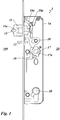
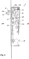
- FIGS. 1 to 18 shown first three embodiments differ in the structural design, in particular as regards the gear 16, which acts between the trigger pin 15 and the latch bolt 11, and as far as the locking device 13, via which the latch bolt 11 in the far extended third position lockable, ie can be blocked, this blocking can be released by retracting the trigger pin 15.
- the transmission device 16 which acts between the trigger member 15 and the latch bolt 11, formed as a two-armed lever 16a.
- This two-armed lever 16a is rotatably mounted on the latch bolt 11, ie on the latch bolt tail, and cooperates with a fixed lip 16p on the lock box 1a. It is essential here that the two-armed lever 16a is connected with its one end to the trigger member 15 (in the illustrated case via a slot connection 11v, s. Fig. 2 to 4 ) and cooperates with its other lever arm with the lip 16p.
- Locking device not shown turned off, so that the latch bolt can be retracted on the lifting device on. In this case, is increased by the cooperating with the lip 16p two-armed lever 16a Retraction speed of the trigger member 15 is achieved relative to the retraction speed of the latch bolt 11, so that the free end of the trigger member 15 is fully retracted into the opening in the inlet slope 11 a of the latch bolt 11.
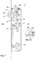
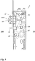
- Locking device 13 shown for the latch bolt It has a wedge-shaped locking element 13, which in its locking position in FIG. 6 cooperates with a stop edge of the latch bolt 11.
- the guide device of the locking element 13 can be supported as one in the lock case 1a Slotted guide be formed, in which engages the slidably received in a vertical slot of the slider 16c locking element 13a.
- two-armed lever 16a cooperates with a two-armed lever 16b, which is spring-loaded on the slider 16c.
- the spring loading of the two-armed lever 16b causes the trigger member 15 is acted upon in its extended position when the latch bolt 11 in its extended position as in FIG. 11 stands.
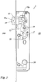
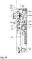
- a special embodiment of the locking device 13 shown in detail As can be seen, it has a pivot bolt 13 a, which is rotatably mounted on a pivot bearing on the latch bolt 11.
- the pivot bolt 13a is actuated by a pressure member which is fixedly arranged on the trigger member 15.
- FIG. 13 shows how the sliding bolt 13b is released from the receiving slot 13c in that the pivot bolt 13a is rotated counterclockwise by the action of the fixed to the trigger member 15 pressure piece.
- the lock 1 has a lock case 1a with a lock box cover, a lock case bottom and a lock face.
- the lock has the following essential interacting components: a Fallen bolt 11, one in the latch bolt 11 movably mounted Entriegelungspin 15, an auxiliary latch 12, a nut lever 18, a non-return 13, a nut 17 and a lock cylinder 20th
- the latch bolt 11 is mounted linearly movable in the lock case 1a.
- the latch bolt 11 has a latch bolt head and a latch bolt tail.
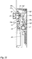
- the latch bolt 11 can assume three positions: a retracted first position (FIG. Fig. 21 ), an extended second position ( Figure 22 ) and a widely extended third position ( Fig. 19 ).
- a retracted first position of the latch bolt 11 is retracted into the lock case 1a.
- In the extended second position and also in the widely extended third position of the latch bolt 11 is extended from the lock case 1 a such that the latch bolt 11 protrudes with its latch bolt head from an associated opening in the lock plate.
- the latch bolt 11 protrudes in the extended second position by 12 mm from the lock case 1a and that the latch bolt 11 protrudes in the far extended third position by 20 mm from the lock case 1a.
- the latch bolt 11 is acted upon by a spring 11f associated therewith, which is referred to below as the latch bolt spring, in the direction of the widely extended third position.
- the latch bolt spring 11f is arranged so that it is supported lock box fixed with its one end and supported with its other end on the latch bolt 11 itself.
- the latch bolt spring 11f is designed as a leg spring.
- the latch bolt head is provided with a trailing edge.
- the trailing edge serves to interact with the stationary door frame 100 or the striking plate of the stationary leaf 110, during the closing process just before the wing 10 is replaced by e.g. Manual closing of the wing reaches the closed position.
- the latch bevel abuts against the stationary door frame 100 or against the strike plate of the passive leaf 110.
- the latch bolt 11 is pushed into the lock case 1a during this stop operation against the action of the latch bolt spring 11f. Once the wing has reached the closed position, the latch bolt moves automatically, i. automatically, in its far extended position.
- the latch bolt tail has a contact area 11a, which serves to cooperate with the nut lever 18 to be described later.
- the contact area 11a is formed as a contact edge.
- the unlocking pin 15 is movably mounted in a receptacle of the latch bolt 11.
- the unlocking pin 15 is used for cooperation with a mounted on the stationary door frame 100 and the inactive leaf 110 lifter.
- the inclusion of the Entriegelungspins 15 in the latch bolt 11 is formed so that the direction of movement of the Entriegelungspins 15 is linear and parallel to the direction of movement of the latch bolt 11.
- the receptacle has an opening in the fall slope. In the far extended position of the latch bolt 1, the maximum extended Entriegelungspin 15 protrudes from the opening in the case slope and thereby projects beyond the front end face of the latch bolt. In the retracted first position and in the extended second position of the latch bolt 11, the unlocking pin 15 is fully in retracted the latch bolt 11. The unlocking pin 15 is not out of the opening in the case slope.
- the unlocking pin 15 has at its lock box-side end a pin 15 z, which is arranged perpendicular to the direction of movement of the Entriegelungspins 15 and the latch bolt 11.
- the pin 15z serves to cooperate with the nut lever 18 to be described later.
- the unlocking pin 15 is acted upon by a spring 15f associated with it in the retraction direction.
- the spring 15f is in the FIGS. 23 and 24 recognizable.
- the spring 15f is supported with its one end on a surface of the latch bolt 11 and with its other end on a driver of Entriegelungspin 15.
- the spring 15f is formed in the illustrated embodiment as a helical compression spring.
- the non-return lock 13 is mounted linearly displaceable in the lock case.
- an edge of the non-return lock 13 on the latch bolt tail and ensures that the latch bolt 11 can not be inserted in its widely extended third position by force from the outside into the lock case 1a.
- the return lock 13 acts in this blocking the latch bolt 11 position as a blocking device, ie locking device, for the extended latch bolt 11.
- This blocking or locking in the extended position of the latch bolt 11 is a tamper protection, when the lock 1 in his the door 10 and the active leaf locking position is located.
- the non-return lock 13 is only in this far extended third position of the latch bolt 11 effective.
- the non-return lock 13 When the latch bolt 11 in its retracted first position ( Fig. 21 ) or in its extended second position ( Fig. 22 ), the non-return lock 13 does not protrude into the range of movement of the latch bolt 11 and is thus switched to be non-operative.
- the non-return lock 13 is acted upon by a spring 13f assigned to it.
- the spring 13f urges the non-return lock 13 into its position blocking the latch bolt 11.
- the nut lever 18 is pivotally mounted in the lock case to a lock box fixed axis 18x.
- the nut lever 18 is not spring-loaded.
- the nut lever 18 is exclusively by entrainment by the other components of the castle, i. by the latch bolt 11, by the unlocking pin 15, and / or by the lock nut 17 moves.
- the free end of the nut lever 18 serves to cooperate with the non-return lock 13.
- the nut lever 18 further has a portion 18 a, which serves to cooperate with the abutment edge 11 a of the latch bolt 11.
- the nut lever 18 on a portion 18z which serves to cooperate with the pin 15z of the unlocking pin 15.
- the lock 1 is designed as a self-locking lock.
- the latch bolt 11 When the door leaf 10 is open, the latch bolt 11 are in its extended second position and the auxiliary latch 12 in its extended position. In this position, the latch bolt 11 by a holding member (not shown in the figures), which coupled with the latch bolt Slider (not shown in the figures) blocked, held until the door leaf 10 reaches its closed position.
- the lock has the auxiliary latch 12 as a detector device for controlling the self-locking mechanism.
- the auxiliary latch 12 is movably mounted in the lock case and can be moved between an extended position in which the auxiliary latch 12 protrudes from an associated opening in the lock plate and a retracted position in which the auxiliary latch 12 is retracted into the lock case 1a.
- the auxiliary latch 12 is urged in the direction of its extended position by a spring 12f assigned to it, which is referred to below as the auxiliary latch spring 12f.
- both the latch bolt 11 and the auxiliary latch 12 are inserted into the lock case. This can be done by striking the door leaf 10 to the door frame 100 or by manual operation of the handle by a user.
- the auxiliary latch remains in its retracted position and the latch bolt 11 is transferred by the self-locking mechanism from its extended second position to its extended third position.
- the self-locking mechanism ensures that the movement of the latch bolt 11 from the second extended position to its third extended position occurs automatically as soon as the door leaf 10 has reached its closed position.
- the lock 1 can be unlocked in various ways: on the one hand by pressing the Entriegelungspins 15 and then inserting the latch bolt 11 by a mounted on the door frame 100 or the inactive leaf 110 lifter, or on the other by manual actuation of a nut 17 connected to the handle or by Actuate the lock cylinder 20th
- Fig. 19 shows the closed position.
- the auxiliary latch 12 stops at the fold of the closed door; So it is partially retracted according to the folded air.
- the latch bolt 11 engages in a lock plate, not shown, which is formed on the associated stationary door frame 100 of the single-leaf door or on a fixed leaf 110 in the case of a double-leaf door.
- the unlocking pin 15 of the latch bolt 11 is maximally extended.
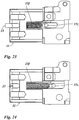
- Fig. 20 shows the door still in the closed position.
- the unlocking pin 15 has already been driven into the latch bolt 11 by the lifter, not shown, mounted in or on the stationary frame or the inactive leaf.
- the unlocking pin 15 has already pivoted so far the nut lever 18 in clockwise direction reaching this position, that the free end of the nut lever 18, the non-return lock 13 is no longer in blocking engagement.
- Fig. 21 the latch bolt 11 is completely retracted by the lifter.
- the unlocking pin 15 is still retracted.
- About the Entriegelungspin 15 of the nut lever 18 is further pivoted in a clockwise direction.
- the latch bolt 11 is in its maximum retracted position, against the action of its associated leg elbow 11f.
- the auxiliary latch 12 is taken by the latch bolt 11 in its fully retracted position.
- the auxiliary latch 12 acting spring 12f is compressed.
- the position in Fig. 21 is obtained when the door 10 passes through the frame 100 when opening and closing the door.
- the completely retracted latch bolt 11 with fully retracted auxiliary latch 12 represents the theoretical case that when passing de wing 10 from the closed position no play remains.
- the position in Fig. 21 is alternatively achieved by rotational actuation of the handle 17 connected to the nut. In this case, the fully retracted position of the latch bolt 11 and the auxiliary latch 12 is practically realized.
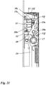
- Fig. 22 shows the door with the wing 10 open.
- the latch bolt 11 is extended to its middle extended position and the auxiliary latch 12 is in its fully extended position.
- the spring is applied by a return spring.
- the return spring 15f is in the sectional detail in the FIGS. 23 and 24 shown.
- the spring 15f is supported at one end on a surface of the latch bolt 11 and at its other end on a driver of the Entriegelungspins 15 and acts on the Entriegelungspin 15 in the retraction direction.
- the spring 15f is formed in the illustrated case as a helical compression spring. This spring action by the return spring 15 f ensures a complete retraction of the unlocking pin 15 in the latch bolt head, so that the unlocking pin 15 no longer protrudes from the slope of the latch bolt 11.
- the spring action is effective as soon as the unlocking pin 15 is pushed over the lifter so far that the non-return lock 13 is switched to be effective and the nut lever 18 is free. From this point, the unlocking pin 15 is no longer retracted by the lifter, but by the spring action by means of the spring 15f, to the extent that it no longer protrudes beyond the slope of the latch bolt 11.
- the re-extension of the unlocking pin 15 is carried out after the lifting of the latch bolt as follows: Starting from the position in Fig. 21 the latch bolt 11 is displaced by the associated spring 11f in the direction of its half extended position. The nut lever 18 is in Counterclockwise about the driver, which is formed at the end 11 a of the latch bolt tail rotated. In a further extension of the latch bolt 11 in the direction Fig. 20 the nut lever 18 runs with its free end on the lower edge of the non-return lock 13 in Fig. 20 to the left and reaches the operating slope of the non-return lock 13. In this position, then after E Gay the operating slope, the non-return 13 by their associated leg spring 13f in the in Fig. 19 moved position shown. Here, the nut lever 18 is further pivoted in the counterclockwise direction, which the unlocking pin 15 against the release pin 15 associated spring 15 f in its maximum extended position in Fig. 19 extending.
Landscapes
- Engineering & Computer Science (AREA)
- Structural Engineering (AREA)
- Lock And Its Accessories (AREA)
Priority Applications (1)
| Application Number | Priority Date | Filing Date | Title |
|---|---|---|---|
| PL13747832T PL2880233T3 (pl) | 2012-08-06 | 2013-08-06 | Urządzenie zamykające do drzwi, okna lub tym podobnych z ryglem opadającym z elementem wyzwalającym i urządzeniem blokującym |
Applications Claiming Priority (2)
| Application Number | Priority Date | Filing Date | Title |
|---|---|---|---|
| DE102012015345 | 2012-08-06 | ||
| PCT/EP2013/066512 WO2014023749A2 (de) | 2012-08-06 | 2013-08-06 | Schlosseinrichtung für eine tür, fenster oder dergleichen mit einem fallenriegel mit auslöseglied und blockiereinrichtung |
Publications (2)
| Publication Number | Publication Date |
|---|---|
| EP2880233A2 EP2880233A2 (de) | 2015-06-10 |
| EP2880233B1 true EP2880233B1 (de) | 2018-09-19 |
Family
ID=48953385
Family Applications (2)
| Application Number | Title | Priority Date | Filing Date |
|---|---|---|---|
| EP13747832.7A Active EP2880233B1 (de) | 2012-08-06 | 2013-08-06 | Schlosseinrichtung für eine tür, fenster oder dergleichen mit einem fallenriegel mit auslöseglied und blockiereinrichtung |
| EP13758763.0A Active EP2880231B1 (de) | 2012-08-06 | 2013-08-06 | Schloss mit einem fallenriegel mit hilfsfalle, halteglied und schieber |
Family Applications After (1)
| Application Number | Title | Priority Date | Filing Date |
|---|---|---|---|
| EP13758763.0A Active EP2880231B1 (de) | 2012-08-06 | 2013-08-06 | Schloss mit einem fallenriegel mit hilfsfalle, halteglied und schieber |
Country Status (4)
| Country | Link |
|---|---|
| EP (2) | EP2880233B1 (pl) |
| ES (1) | ES2698956T3 (pl) |
| PL (1) | PL2880233T3 (pl) |
| WO (2) | WO2014023750A1 (pl) |
Families Citing this family (1)
| Publication number | Priority date | Publication date | Assignee | Title |
|---|---|---|---|---|
| CN114046108B (zh) * | 2021-11-19 | 2025-01-10 | 上海向安实业有限公司 | 逃生门锁 |
Family Cites Families (13)
| Publication number | Priority date | Publication date | Assignee | Title |
|---|---|---|---|---|
| US5469723A (en) * | 1990-07-25 | 1995-11-28 | Litwin; Noel | Safety locks |
| US5474342A (en) * | 1993-08-04 | 1995-12-12 | Smith; Jerry R. | Door latch actuator |
| EP0866905A4 (en) * | 1995-12-12 | 1999-01-20 | Jerry R Smith | OPERATING DEVICE FOR A DOOR |
| DE19652601C1 (de) | 1996-12-18 | 1998-06-25 | Dorma Gmbh & Co Kg | Ent- und Verriegelung für eine einen Standflügel und einen Gangflügel aufweisende Tür |
| DE10063784B4 (de) * | 2000-12-21 | 2007-11-15 | Wilka Schließtechnik GmbH | Schloss |
| FI115066B (fi) | 2001-01-26 | 2005-02-28 | Abloy Oy | Järjestely vinoteljen ulostulopituuden ohjaamiseksi ovenlukossa |
| DE102004013646A1 (de) * | 2004-03-12 | 2005-09-29 | Wilka Schließtechnik GmbH | Panikschloss |
| DE102006030552A1 (de) * | 2005-07-14 | 2007-01-18 | Kfv Karl Fliether Gmbh & Co. Kg | Fluchttürschloss |
| FI20065200L (fi) * | 2006-03-28 | 2007-09-29 | Bjoerkboda Laas Oy Ab | Ovenlukon aputelkijärjestely |
| ES2388119T3 (es) * | 2008-06-05 | 2012-10-09 | Cisa S.P.A. | Cerradura de seguridad universal |
| CN102137979A (zh) * | 2008-08-05 | 2011-07-27 | 西莎股份公司 | 推拉门的通用锁 |
| DE102009003860B4 (de) * | 2009-04-30 | 2015-10-22 | Wilka Schließtechnik GmbH | Panikschloss mit durch Betätigung eines der Riegelstirn zugeordneten Auslösers aushebbarer Zuhaltung |
| DE202011001842U1 (de) | 2011-01-14 | 2011-04-21 | Bks Gmbh | Verriegelungseinrichtung |
-
2013
- 2013-08-06 EP EP13747832.7A patent/EP2880233B1/de active Active
- 2013-08-06 PL PL13747832T patent/PL2880233T3/pl unknown
- 2013-08-06 EP EP13758763.0A patent/EP2880231B1/de active Active
- 2013-08-06 WO PCT/EP2013/066513 patent/WO2014023750A1/de not_active Ceased
- 2013-08-06 ES ES13747832T patent/ES2698956T3/es active Active
- 2013-08-06 WO PCT/EP2013/066512 patent/WO2014023749A2/de not_active Ceased
Non-Patent Citations (1)
| Title |
|---|
| None * |
Also Published As
| Publication number | Publication date |
|---|---|
| WO2014023750A1 (de) | 2014-02-13 |
| ES2698956T3 (es) | 2019-02-06 |
| WO2014023749A3 (de) | 2014-06-26 |
| WO2014023749A2 (de) | 2014-02-13 |
| EP2880231B1 (de) | 2018-11-07 |
| EP2880233A2 (de) | 2015-06-10 |
| EP2880231A1 (de) | 2015-06-10 |
| PL2880233T3 (pl) | 2019-02-28 |
Similar Documents
| Publication | Publication Date | Title |
|---|---|---|
| EP2951369B1 (de) | Panikschloss | |
| EP3832055B1 (de) | Verriegelungseinheit für eine schliessanlage einer tür | |
| WO2007104499A2 (de) | Verriegelungssystem für eine tür | |
| EP2757216B1 (de) | Schlosseinrichtung mit Riegelstangen-Betätigungshandhabe | |
| CH657417A5 (de) | Treibstangenverschluss ohne panikfunktion, insbesondere fuer den standfluegel zweifluegeliger tueren. | |
| EP0833997B1 (de) | Schliesseinrichtung mit flügelfangeinrichtung | |
| AT500183B1 (de) | Schubstangenbetätigbarer verschluss für fenster, türen oder dergleichen | |
| WO2016113044A1 (de) | Schloss | |
| EP3569800B1 (de) | Schloss, insbesondere sperrfallenschloss | |
| WO2013113854A1 (de) | Türöffner und tür mit türöffner | |
| EP2880233B1 (de) | Schlosseinrichtung für eine tür, fenster oder dergleichen mit einem fallenriegel mit auslöseglied und blockiereinrichtung | |
| EP3426867B1 (de) | Schloss | |
| DE102015000606A1 (de) | Verriegelungsvorrichtung für einen schwenkbar gelagerten Flügel | |
| DE3931101A1 (de) | Automatisch verriegelndes schloss | |
| EP0974721B1 (de) | Mehrriegelschloss | |
| DE102013012203B4 (de) | Elektrischer Türöffner sowie ein Passivflügelschloss mit einem solchen Türöffner | |
| DE19857432B4 (de) | Schließeinrichtung für Gebäudetüren oder Gebäudefenster | |
| EP3299551B1 (de) | Verriegelungsvorrichtung mit ausgleichsschieber und übertragungselement | |
| EP3216952B1 (de) | Verriegelungseinrichtung | |
| DE102014102041A1 (de) | Schließkantenklappe | |
| EP2642051A2 (de) | Treibriegel-Schaltschloss | |
| DE19738242C2 (de) | Schloß für Sicherheitstüren | |
| EP2362042B1 (de) | Panik-Treibriegelschloss | |
| EP2559834B1 (de) | Schliessvorrichtung für fahrzeugtüren | |
| DE202015000106U1 (de) | Schloss |
Legal Events
| Date | Code | Title | Description |
|---|---|---|---|
| PUAI | Public reference made under article 153(3) epc to a published international application that has entered the european phase |
Free format text: ORIGINAL CODE: 0009012 |
|
| 17P | Request for examination filed |
Effective date: 20150210 |
|
| AK | Designated contracting states |
Kind code of ref document: A2 Designated state(s): AL AT BE BG CH CY CZ DE DK EE ES FI FR GB GR HR HU IE IS IT LI LT LU LV MC MK MT NL NO PL PT RO RS SE SI SK SM TR |
|
| AX | Request for extension of the european patent |
Extension state: BA ME |
|
| DAX | Request for extension of the european patent (deleted) | ||
| GRAP | Despatch of communication of intention to grant a patent |
Free format text: ORIGINAL CODE: EPIDOSNIGR1 |
|
| STAA | Information on the status of an ep patent application or granted ep patent |
Free format text: STATUS: GRANT OF PATENT IS INTENDED |
|
| INTG | Intention to grant announced |
Effective date: 20180329 |
|
| GRAS | Grant fee paid |
Free format text: ORIGINAL CODE: EPIDOSNIGR3 |
|
| GRAA | (expected) grant |
Free format text: ORIGINAL CODE: 0009210 |
|
| STAA | Information on the status of an ep patent application or granted ep patent |
Free format text: STATUS: THE PATENT HAS BEEN GRANTED |
|
| AK | Designated contracting states |
Kind code of ref document: B1 Designated state(s): AL AT BE BG CH CY CZ DE DK EE ES FI FR GB GR HR HU IE IS IT LI LT LU LV MC MK MT NL NO PL PT RO RS SE SI SK SM TR |
|
| REG | Reference to a national code |
Ref country code: GB Ref legal event code: FG4D Free format text: NOT ENGLISH |
|
| REG | Reference to a national code |
Ref country code: CH Ref legal event code: EP |
|
| REG | Reference to a national code |
Ref country code: AT Ref legal event code: REF Ref document number: 1043451 Country of ref document: AT Kind code of ref document: T Effective date: 20181015 |
|
| REG | Reference to a national code |
Ref country code: IE Ref legal event code: FG4D Free format text: LANGUAGE OF EP DOCUMENT: GERMAN |
|
| REG | Reference to a national code |
Ref country code: DE Ref legal event code: R096 Ref document number: 502013011131 Country of ref document: DE |
|
| REG | Reference to a national code |
Ref country code: SE Ref legal event code: TRGR |
|
| REG | Reference to a national code |
Ref country code: NL Ref legal event code: FP |
|
| PG25 | Lapsed in a contracting state [announced via postgrant information from national office to epo] |
Ref country code: RS Free format text: LAPSE BECAUSE OF FAILURE TO SUBMIT A TRANSLATION OF THE DESCRIPTION OR TO PAY THE FEE WITHIN THE PRESCRIBED TIME-LIMIT Effective date: 20180919 Ref country code: LT Free format text: LAPSE BECAUSE OF FAILURE TO SUBMIT A TRANSLATION OF THE DESCRIPTION OR TO PAY THE FEE WITHIN THE PRESCRIBED TIME-LIMIT Effective date: 20180919 Ref country code: BG Free format text: LAPSE BECAUSE OF FAILURE TO SUBMIT A TRANSLATION OF THE DESCRIPTION OR TO PAY THE FEE WITHIN THE PRESCRIBED TIME-LIMIT Effective date: 20181219 Ref country code: NO Free format text: LAPSE BECAUSE OF FAILURE TO SUBMIT A TRANSLATION OF THE DESCRIPTION OR TO PAY THE FEE WITHIN THE PRESCRIBED TIME-LIMIT Effective date: 20181219 Ref country code: FI Free format text: LAPSE BECAUSE OF FAILURE TO SUBMIT A TRANSLATION OF THE DESCRIPTION OR TO PAY THE FEE WITHIN THE PRESCRIBED TIME-LIMIT Effective date: 20180919 Ref country code: GR Free format text: LAPSE BECAUSE OF FAILURE TO SUBMIT A TRANSLATION OF THE DESCRIPTION OR TO PAY THE FEE WITHIN THE PRESCRIBED TIME-LIMIT Effective date: 20181220 |
|
| REG | Reference to a national code |
Ref country code: ES Ref legal event code: FG2A Ref document number: 2698956 Country of ref document: ES Kind code of ref document: T3 Effective date: 20190206 |
|
| REG | Reference to a national code |
Ref country code: LT Ref legal event code: MG4D |
|
| PG25 | Lapsed in a contracting state [announced via postgrant information from national office to epo] |
Ref country code: LV Free format text: LAPSE BECAUSE OF FAILURE TO SUBMIT A TRANSLATION OF THE DESCRIPTION OR TO PAY THE FEE WITHIN THE PRESCRIBED TIME-LIMIT Effective date: 20180919 Ref country code: AL Free format text: LAPSE BECAUSE OF FAILURE TO SUBMIT A TRANSLATION OF THE DESCRIPTION OR TO PAY THE FEE WITHIN THE PRESCRIBED TIME-LIMIT Effective date: 20180919 Ref country code: HR Free format text: LAPSE BECAUSE OF FAILURE TO SUBMIT A TRANSLATION OF THE DESCRIPTION OR TO PAY THE FEE WITHIN THE PRESCRIBED TIME-LIMIT Effective date: 20180919 |
|
| PG25 | Lapsed in a contracting state [announced via postgrant information from national office to epo] |
Ref country code: EE Free format text: LAPSE BECAUSE OF FAILURE TO SUBMIT A TRANSLATION OF THE DESCRIPTION OR TO PAY THE FEE WITHIN THE PRESCRIBED TIME-LIMIT Effective date: 20180919 Ref country code: RO Free format text: LAPSE BECAUSE OF FAILURE TO SUBMIT A TRANSLATION OF THE DESCRIPTION OR TO PAY THE FEE WITHIN THE PRESCRIBED TIME-LIMIT Effective date: 20180919 Ref country code: CZ Free format text: LAPSE BECAUSE OF FAILURE TO SUBMIT A TRANSLATION OF THE DESCRIPTION OR TO PAY THE FEE WITHIN THE PRESCRIBED TIME-LIMIT Effective date: 20180919 Ref country code: IS Free format text: LAPSE BECAUSE OF FAILURE TO SUBMIT A TRANSLATION OF THE DESCRIPTION OR TO PAY THE FEE WITHIN THE PRESCRIBED TIME-LIMIT Effective date: 20190119 |
|
| PG25 | Lapsed in a contracting state [announced via postgrant information from national office to epo] |
Ref country code: SM Free format text: LAPSE BECAUSE OF FAILURE TO SUBMIT A TRANSLATION OF THE DESCRIPTION OR TO PAY THE FEE WITHIN THE PRESCRIBED TIME-LIMIT Effective date: 20180919 Ref country code: SK Free format text: LAPSE BECAUSE OF FAILURE TO SUBMIT A TRANSLATION OF THE DESCRIPTION OR TO PAY THE FEE WITHIN THE PRESCRIBED TIME-LIMIT Effective date: 20180919 Ref country code: PT Free format text: LAPSE BECAUSE OF FAILURE TO SUBMIT A TRANSLATION OF THE DESCRIPTION OR TO PAY THE FEE WITHIN THE PRESCRIBED TIME-LIMIT Effective date: 20190119 |
|
| REG | Reference to a national code |
Ref country code: DE Ref legal event code: R097 Ref document number: 502013011131 Country of ref document: DE |
|
| PLBE | No opposition filed within time limit |
Free format text: ORIGINAL CODE: 0009261 |
|
| STAA | Information on the status of an ep patent application or granted ep patent |
Free format text: STATUS: NO OPPOSITION FILED WITHIN TIME LIMIT |
|
| PG25 | Lapsed in a contracting state [announced via postgrant information from national office to epo] |
Ref country code: DK Free format text: LAPSE BECAUSE OF FAILURE TO SUBMIT A TRANSLATION OF THE DESCRIPTION OR TO PAY THE FEE WITHIN THE PRESCRIBED TIME-LIMIT Effective date: 20180919 |
|
| 26N | No opposition filed |
Effective date: 20190620 |
|
| PG25 | Lapsed in a contracting state [announced via postgrant information from national office to epo] |
Ref country code: SI Free format text: LAPSE BECAUSE OF FAILURE TO SUBMIT A TRANSLATION OF THE DESCRIPTION OR TO PAY THE FEE WITHIN THE PRESCRIBED TIME-LIMIT Effective date: 20180919 |
|
| REG | Reference to a national code |
Ref country code: SE Ref legal event code: EUG |
|
| PG25 | Lapsed in a contracting state [announced via postgrant information from national office to epo] |
Ref country code: SE Free format text: LAPSE BECAUSE OF NON-PAYMENT OF DUE FEES Effective date: 20190807 |
|
| PG25 | Lapsed in a contracting state [announced via postgrant information from national office to epo] |
Ref country code: LU Free format text: LAPSE BECAUSE OF NON-PAYMENT OF DUE FEES Effective date: 20190806 Ref country code: LI Free format text: LAPSE BECAUSE OF NON-PAYMENT OF DUE FEES Effective date: 20190831 Ref country code: CH Free format text: LAPSE BECAUSE OF NON-PAYMENT OF DUE FEES Effective date: 20190831 Ref country code: MC Free format text: LAPSE BECAUSE OF FAILURE TO SUBMIT A TRANSLATION OF THE DESCRIPTION OR TO PAY THE FEE WITHIN THE PRESCRIBED TIME-LIMIT Effective date: 20180919 |
|
| REG | Reference to a national code |
Ref country code: BE Ref legal event code: MM Effective date: 20190831 |
|
| PG25 | Lapsed in a contracting state [announced via postgrant information from national office to epo] |
Ref country code: IE Free format text: LAPSE BECAUSE OF NON-PAYMENT OF DUE FEES Effective date: 20190806 |
|
| PG25 | Lapsed in a contracting state [announced via postgrant information from national office to epo] |
Ref country code: IT Free format text: LAPSE BECAUSE OF NON-PAYMENT OF DUE FEES Effective date: 20190806 Ref country code: BE Free format text: LAPSE BECAUSE OF NON-PAYMENT OF DUE FEES Effective date: 20190831 |
|
| REG | Reference to a national code |
Ref country code: AT Ref legal event code: MM01 Ref document number: 1043451 Country of ref document: AT Kind code of ref document: T Effective date: 20190806 |
|
| PG25 | Lapsed in a contracting state [announced via postgrant information from national office to epo] |
Ref country code: AT Free format text: LAPSE BECAUSE OF NON-PAYMENT OF DUE FEES Effective date: 20190806 |
|
| PG25 | Lapsed in a contracting state [announced via postgrant information from national office to epo] |
Ref country code: CY Free format text: LAPSE BECAUSE OF FAILURE TO SUBMIT A TRANSLATION OF THE DESCRIPTION OR TO PAY THE FEE WITHIN THE PRESCRIBED TIME-LIMIT Effective date: 20180919 |
|
| PG25 | Lapsed in a contracting state [announced via postgrant information from national office to epo] |
Ref country code: HU Free format text: LAPSE BECAUSE OF FAILURE TO SUBMIT A TRANSLATION OF THE DESCRIPTION OR TO PAY THE FEE WITHIN THE PRESCRIBED TIME-LIMIT; INVALID AB INITIO Effective date: 20130806 Ref country code: MT Free format text: LAPSE BECAUSE OF FAILURE TO SUBMIT A TRANSLATION OF THE DESCRIPTION OR TO PAY THE FEE WITHIN THE PRESCRIBED TIME-LIMIT Effective date: 20180919 |
|
| PGFP | Annual fee paid to national office [announced via postgrant information from national office to epo] |
Ref country code: NL Payment date: 20210813 Year of fee payment: 9 |
|
| PGFP | Annual fee paid to national office [announced via postgrant information from national office to epo] |
Ref country code: FR Payment date: 20210727 Year of fee payment: 9 |
|
| PGFP | Annual fee paid to national office [announced via postgrant information from national office to epo] |
Ref country code: ES Payment date: 20210906 Year of fee payment: 9 Ref country code: GB Payment date: 20210714 Year of fee payment: 9 Ref country code: PL Payment date: 20210713 Year of fee payment: 9 |
|
| PG25 | Lapsed in a contracting state [announced via postgrant information from national office to epo] |
Ref country code: MK Free format text: LAPSE BECAUSE OF FAILURE TO SUBMIT A TRANSLATION OF THE DESCRIPTION OR TO PAY THE FEE WITHIN THE PRESCRIBED TIME-LIMIT Effective date: 20180919 |
|
| REG | Reference to a national code |
Ref country code: NL Ref legal event code: MM Effective date: 20220901 |
|
| GBPC | Gb: european patent ceased through non-payment of renewal fee |
Effective date: 20220806 |
|
| PG25 | Lapsed in a contracting state [announced via postgrant information from national office to epo] |
Ref country code: NL Free format text: LAPSE BECAUSE OF NON-PAYMENT OF DUE FEES Effective date: 20220901 |
|
| PG25 | Lapsed in a contracting state [announced via postgrant information from national office to epo] |
Ref country code: FR Free format text: LAPSE BECAUSE OF NON-PAYMENT OF DUE FEES Effective date: 20220831 |
|
| REG | Reference to a national code |
Ref country code: ES Ref legal event code: FD2A Effective date: 20230926 |
|
| PG25 | Lapsed in a contracting state [announced via postgrant information from national office to epo] |
Ref country code: GB Free format text: LAPSE BECAUSE OF NON-PAYMENT OF DUE FEES Effective date: 20220806 Ref country code: ES Free format text: LAPSE BECAUSE OF NON-PAYMENT OF DUE FEES Effective date: 20220807 |
|
| PG25 | Lapsed in a contracting state [announced via postgrant information from national office to epo] |
Ref country code: PL Free format text: LAPSE BECAUSE OF NON-PAYMENT OF DUE FEES Effective date: 20220806 |
|
| PG25 | Lapsed in a contracting state [announced via postgrant information from national office to epo] |
Ref country code: TR Free format text: LAPSE BECAUSE OF NON-PAYMENT OF DUE FEES Effective date: 20190806 |
|
| PGFP | Annual fee paid to national office [announced via postgrant information from national office to epo] |
Ref country code: DE Payment date: 20250708 Year of fee payment: 13 |