EP2867533B1 - Verfahren und pumpenanordnung zum evakuieren einer kammer - Google Patents
Verfahren und pumpenanordnung zum evakuieren einer kammer Download PDFInfo
- Publication number
- EP2867533B1 EP2867533B1 EP13727952.7A EP13727952A EP2867533B1 EP 2867533 B1 EP2867533 B1 EP 2867533B1 EP 13727952 A EP13727952 A EP 13727952A EP 2867533 B1 EP2867533 B1 EP 2867533B1
- Authority
- EP
- European Patent Office
- Prior art keywords
- booster pump
- pump
- chamber
- gas
- housing
- Prior art date
- Legal status (The legal status is an assumption and is not a legal conclusion. Google has not performed a legal analysis and makes no representation as to the accuracy of the status listed.)
- Active
Links
Images


Classifications
-
- F—MECHANICAL ENGINEERING; LIGHTING; HEATING; WEAPONS; BLASTING
- F04—POSITIVE - DISPLACEMENT MACHINES FOR LIQUIDS; PUMPS FOR LIQUIDS OR ELASTIC FLUIDS
- F04C—ROTARY-PISTON, OR OSCILLATING-PISTON, POSITIVE-DISPLACEMENT MACHINES FOR LIQUIDS; ROTARY-PISTON, OR OSCILLATING-PISTON, POSITIVE-DISPLACEMENT PUMPS
- F04C28/00—Control of, monitoring of, or safety arrangements for, pumps or pumping installations specially adapted for elastic fluids
- F04C28/02—Control of, monitoring of, or safety arrangements for, pumps or pumping installations specially adapted for elastic fluids specially adapted for several pumps connected in series or in parallel
-
- F—MECHANICAL ENGINEERING; LIGHTING; HEATING; WEAPONS; BLASTING
- F04—POSITIVE - DISPLACEMENT MACHINES FOR LIQUIDS; PUMPS FOR LIQUIDS OR ELASTIC FLUIDS
- F04C—ROTARY-PISTON, OR OSCILLATING-PISTON, POSITIVE-DISPLACEMENT MACHINES FOR LIQUIDS; ROTARY-PISTON, OR OSCILLATING-PISTON, POSITIVE-DISPLACEMENT PUMPS
- F04C14/00—Control of, monitoring of, or safety arrangements for, machines, pumps or pumping installations
- F04C14/08—Control of, monitoring of, or safety arrangements for, machines, pumps or pumping installations characterised by varying the rotational speed
-
- F—MECHANICAL ENGINEERING; LIGHTING; HEATING; WEAPONS; BLASTING
- F04—POSITIVE - DISPLACEMENT MACHINES FOR LIQUIDS; PUMPS FOR LIQUIDS OR ELASTIC FLUIDS
- F04C—ROTARY-PISTON, OR OSCILLATING-PISTON, POSITIVE-DISPLACEMENT MACHINES FOR LIQUIDS; ROTARY-PISTON, OR OSCILLATING-PISTON, POSITIVE-DISPLACEMENT PUMPS
- F04C18/00—Rotary-piston pumps specially adapted for elastic fluids
- F04C18/08—Rotary-piston pumps specially adapted for elastic fluids of intermeshing-engagement type, i.e. with engagement of co-operating members similar to that of toothed gearing
- F04C18/12—Rotary-piston pumps specially adapted for elastic fluids of intermeshing-engagement type, i.e. with engagement of co-operating members similar to that of toothed gearing of other than internal-axis type
- F04C18/14—Rotary-piston pumps specially adapted for elastic fluids of intermeshing-engagement type, i.e. with engagement of co-operating members similar to that of toothed gearing of other than internal-axis type with toothed rotary pistons
- F04C18/16—Rotary-piston pumps specially adapted for elastic fluids of intermeshing-engagement type, i.e. with engagement of co-operating members similar to that of toothed gearing of other than internal-axis type with toothed rotary pistons with helical teeth, e.g. chevron-shaped, screw type
-
- F—MECHANICAL ENGINEERING; LIGHTING; HEATING; WEAPONS; BLASTING
- F04—POSITIVE - DISPLACEMENT MACHINES FOR LIQUIDS; PUMPS FOR LIQUIDS OR ELASTIC FLUIDS
- F04C—ROTARY-PISTON, OR OSCILLATING-PISTON, POSITIVE-DISPLACEMENT MACHINES FOR LIQUIDS; ROTARY-PISTON, OR OSCILLATING-PISTON, POSITIVE-DISPLACEMENT PUMPS
- F04C2/00—Rotary-piston machines or pumps
- F04C2/08—Rotary-piston machines or pumps of intermeshing-engagement type, i.e. with engagement of co-operating members similar to that of toothed gearing
- F04C2/10—Rotary-piston machines or pumps of intermeshing-engagement type, i.e. with engagement of co-operating members similar to that of toothed gearing of internal-axis type with the outer member having more teeth or tooth-equivalents, e.g. rollers, than the inner member
-
- F—MECHANICAL ENGINEERING; LIGHTING; HEATING; WEAPONS; BLASTING
- F04—POSITIVE - DISPLACEMENT MACHINES FOR LIQUIDS; PUMPS FOR LIQUIDS OR ELASTIC FLUIDS
- F04C—ROTARY-PISTON, OR OSCILLATING-PISTON, POSITIVE-DISPLACEMENT MACHINES FOR LIQUIDS; ROTARY-PISTON, OR OSCILLATING-PISTON, POSITIVE-DISPLACEMENT PUMPS
- F04C23/00—Combinations of two or more pumps, each being of rotary-piston or oscillating-piston type, specially adapted for elastic fluids; Pumping installations specially adapted for elastic fluids; Multi-stage pumps specially adapted for elastic fluids
- F04C23/005—Combinations of two or more pumps, each being of rotary-piston or oscillating-piston type, specially adapted for elastic fluids; Pumping installations specially adapted for elastic fluids; Multi-stage pumps specially adapted for elastic fluids of dissimilar working principle
-
- F—MECHANICAL ENGINEERING; LIGHTING; HEATING; WEAPONS; BLASTING
- F04—POSITIVE - DISPLACEMENT MACHINES FOR LIQUIDS; PUMPS FOR LIQUIDS OR ELASTIC FLUIDS
- F04C—ROTARY-PISTON, OR OSCILLATING-PISTON, POSITIVE-DISPLACEMENT MACHINES FOR LIQUIDS; ROTARY-PISTON, OR OSCILLATING-PISTON, POSITIVE-DISPLACEMENT PUMPS
- F04C25/00—Adaptations of pumps for special use of pumps for elastic fluids
- F04C25/02—Adaptations of pumps for special use of pumps for elastic fluids for producing high vacuum
-
- F—MECHANICAL ENGINEERING; LIGHTING; HEATING; WEAPONS; BLASTING
- F04—POSITIVE - DISPLACEMENT MACHINES FOR LIQUIDS; PUMPS FOR LIQUIDS OR ELASTIC FLUIDS
- F04C—ROTARY-PISTON, OR OSCILLATING-PISTON, POSITIVE-DISPLACEMENT MACHINES FOR LIQUIDS; ROTARY-PISTON, OR OSCILLATING-PISTON, POSITIVE-DISPLACEMENT PUMPS
- F04C28/00—Control of, monitoring of, or safety arrangements for, pumps or pumping installations specially adapted for elastic fluids
- F04C28/06—Control of, monitoring of, or safety arrangements for, pumps or pumping installations specially adapted for elastic fluids specially adapted for stopping, starting, idling or no-load operation
-
- F—MECHANICAL ENGINEERING; LIGHTING; HEATING; WEAPONS; BLASTING
- F04—POSITIVE - DISPLACEMENT MACHINES FOR LIQUIDS; PUMPS FOR LIQUIDS OR ELASTIC FLUIDS
- F04C—ROTARY-PISTON, OR OSCILLATING-PISTON, POSITIVE-DISPLACEMENT MACHINES FOR LIQUIDS; ROTARY-PISTON, OR OSCILLATING-PISTON, POSITIVE-DISPLACEMENT PUMPS
- F04C18/00—Rotary-piston pumps specially adapted for elastic fluids
- F04C18/08—Rotary-piston pumps specially adapted for elastic fluids of intermeshing-engagement type, i.e. with engagement of co-operating members similar to that of toothed gearing
- F04C18/082—Details specially related to intermeshing engagement type pumps
- F04C18/084—Toothed wheels
-
- F—MECHANICAL ENGINEERING; LIGHTING; HEATING; WEAPONS; BLASTING
- F04—POSITIVE - DISPLACEMENT MACHINES FOR LIQUIDS; PUMPS FOR LIQUIDS OR ELASTIC FLUIDS
- F04C—ROTARY-PISTON, OR OSCILLATING-PISTON, POSITIVE-DISPLACEMENT MACHINES FOR LIQUIDS; ROTARY-PISTON, OR OSCILLATING-PISTON, POSITIVE-DISPLACEMENT PUMPS
- F04C18/00—Rotary-piston pumps specially adapted for elastic fluids
- F04C18/08—Rotary-piston pumps specially adapted for elastic fluids of intermeshing-engagement type, i.e. with engagement of co-operating members similar to that of toothed gearing
- F04C18/082—Details specially related to intermeshing engagement type pumps
- F04C18/086—Carter
-
- F—MECHANICAL ENGINEERING; LIGHTING; HEATING; WEAPONS; BLASTING
- F04—POSITIVE - DISPLACEMENT MACHINES FOR LIQUIDS; PUMPS FOR LIQUIDS OR ELASTIC FLUIDS
- F04C—ROTARY-PISTON, OR OSCILLATING-PISTON, POSITIVE-DISPLACEMENT MACHINES FOR LIQUIDS; ROTARY-PISTON, OR OSCILLATING-PISTON, POSITIVE-DISPLACEMENT PUMPS
- F04C2220/00—Application
- F04C2220/30—Use in a chemical vapor deposition [CVD] process or in a similar process
Definitions
- the invention relates to a method and a pump assembly for evacuating a chamber.
- the pump assembly which is connected to the chamber, includes a booster pump and a subsequent backing pump.
- Such a pump arrangement is known from WO 2006/082366 known.
- a chamber is evacuated within a short time to a predetermined vacuum.
- An example are lock chambers, through which products are introduced into a vacuum space.
- the products may be, for example, bulk goods such as solar cells, displays, etc., in which individual manufacturing steps are carried out in the vacuum space.
- Such products are to be introduced with ever shorter cycle times in the vacuum space.
- lock chambers with a volume of a few 100 l to be evacuated in significantly less than 10 s to a pressure of less than 10 -2 mbar.
- Pump assemblies of two pumps connected in series are usually used to evacuate such lock chambers, the first pump usually being referred to as a booster pump and the subsequent pump as a fore pump.
- the invention is based on the object to present a method and a pump assembly that allow the rapid evacuation of a chamber with reduced equipment expense. Based on the above-mentioned prior art, the object is achieved with the features of the independent claims. Advantageous embodiments can be found in the subclaims.
- the booster pump is first accelerated when the input is closed. Gas from the chamber to be evacuated is then admitted into the booster pump, so that the booster pump is temporarily removed an excess power that goes beyond the power provided by the drive of the booster pump.
- the gas delivered to the booster pump outlet is delivered through a bypass valve as long as the output pressure of the booster pump is above a predetermined threshold.
- the gas is sent to the fore pump when the output pressure of the booster pump has dropped below the threshold.
- the gas supplied by the booster pump is compressed by the forepump.
- booster pump and fore pump clarify the order of the pump in the pump arrangement.
- a limitation with regard to the design of the pump is not associated with these terms.
- the invention has recognized that it is possible by accelerating the booster pump and the subsequent removal of the excess power to promote the gas from the chamber under such high pressure to the output of the booster pump that the gas can be discharged directly bypassing the fore pump. Only when the evacuation process has progressed so far that the booster pump is no longer able to compress the gas to the appropriate pressure, the fore pump is added for further compression.
- the invention makes it possible to design the backing pump not only for a smaller volume flow, but also for a smaller mass flow than the booster pump.
- the outlet of the bypass valve is at atmospheric pressure.
- the threshold value corresponds in this case to the atmospheric pressure. So the gas exits through the bypass valve, as long as the output pressure of the booster pump is above the atmospheric pressure.
- the outlet pressure of the booster pump can be at least 1 bar, preferably at least 2 bar, more preferably at least 3 bar above atmospheric pressure.
- the compressed with the forepumping gas can also be discharged at atmospheric pressure to the environment.
- the evacuation process is in the chamber regularly at atmospheric pressure, so that the evacuation process starts at atmospheric pressure.
- the input of the booster pump is closed, so that no gas from the chamber can enter the booster pump.
- the evacuation process then begins at the time gas is introduced into the booster pump.
- the booster pump In order to be able to deliver a large volume flow at high pressure (e.g., atmospheric pressure) at the beginning of the evacuation process, the booster pump must provide a high compression capacity.
- the high compression capacity is provided by temporarily removing more compression power from the booster pump during the evacuation process than the booster pump drive provides. The excess power beyond the drive power is taken from the kinetic energy of the booster pump. The booster pump is thus braked and the speed of the pump is reduced.
- the power taken in the booster pump can be very clearly above the drive power. It is possible, for example, that the excess power in the tip is more than 50%, preferably more than 100%, more preferably more than 200% of the drive power. With an oversize performance of 100%, the compression capacity is twice as high as the drive power.
- the excess power is not only taken momentarily, but over a certain period of time.
- the period during which excess pressure is taken for example, over 10%, preferably more than 20%, more preferably extend over 50% of the evacuation process.
- the speed of the booster pump can be reduced by removing the excess power by at least 5%, preferably at least 10%, more preferably at least 25% percent.
- the pump In order for it to be possible to remove excess power from the pump to such an extent, the pump must be set to a state in which sufficient kinetic energy is available before the evacuation process begins. The pump is therefore accelerated before the start of the evacuation process.
- the speed of the booster pump at the beginning of the evacuation process is preferably higher than 8000 rpm, more preferably higher than 10,000 rpm, more preferably higher than 12000 rpm.
- the diameter of the parts in rotation is preferably greater than 5 cm, more preferably greater than 10 cm, more preferably greater than 20 cm.
- booster pump If the gas is admitted from the chamber at substantially atmospheric pressure in the booster pump, the booster pump is exposed to a sudden load.
- a screw pump is used as a booster pump, whose preferred design is explained in more detail below.
- the forepump can for example, be a conventional liquid ring vacuum pump.
- the period in which the booster pump is taken excess power for example, 1 s
- the period of removal of excess power is preferably at least 5%, more preferably at least 10% of the cycle time.
- the power taken from the booster pump is less than the drive power, so that the booster pump is accelerated.
- the invention also relates to a pump arrangement.
- the pump arrangement comprises a booster pump and a fore pump, wherein the output of the booster pump is connected to the input of the fore pump. Between the booster pump and the fore pump, a bypass valve is arranged, through which the pumped with the booster pump gas can be delivered bypassing the backing pump.
- the pump assembly further includes a controller configured to provide a control signal when the speed of the booster pump is above a predetermined speed threshold. The speed threshold value is set so that the booster pump is ready for the removal of an excess power after exceeding the relevant speed.
- Such a pump arrangement is suitable for evacuating a chamber according to the method according to the invention in a short time.
- the control signal may be communicated to a controller of the chamber to be evacuated to notify that the booster pump is ready for the next evacuation process.
- the control of the chamber can then open the input of the booster pump via which the booster pump is connected to the chamber.
- the gas from the chamber then enters the booster pump and the chamber is evacuated quickly. With the entry of the gas into the booster pump, the load increases abruptly, so that the speed of the booster pump is reduced.
- the control unit of the booster pump can also be designed to accelerate the booster pump before the start of the evacuation process so that the speed threshold is exceeded.
- the speed threshold is preferably above the delivery speed of the booster pump. Delivery speed refers to the speed, which is set as a stationary state when the intake pressure is 100 mbar.
- the drive power at pump speed corresponds to the pump power, which means that the speed of the booster pump remains constant.
- the speed threshold may be 10%, preferably 30%, more preferably 50% higher than the delivery speed. In absolute terms, the speed threshold value may be, for example, at least 8,000 rpm, preferably at least 10,000 rpm, more preferably at least 12,000 rpm.
- booster pumps which are considered for an application within the scope of the invention, operated at much lower speeds. A speed of 6,000 rpm is not regularly exceeded during the operation of such booster pumps. Also in the method according to the invention, the booster pump can be accelerated beyond the delivery speed.
- the arrangement according to the invention can also comprise the chamber to be evacuated.
- the controller of the assembly may then be configured to open the input of the pump via which the booster pump is connected to the chamber after the speed threshold has been exceeded. Further, the controller may be configured to keep the input closed while the booster pump is accelerating.
- a screw pump is used as booster pump, in which the screws of two threads are engaged with each other so that the gas is conveyed between the threads from a suction side to a pressure side.
- the screws preferably have two threads, so that the forces occurring in the longitudinal direction of the screws cancel each other out.
- the threads of the screw are preferably formed slaughter marc.
- a point symmetry of the screws can be such that the screws are imaged by themselves by a rotation about the longitudinal axis by 180 °.
- the diameter of the screws is preferably greater than 10 cm, more preferably greater than 15 cm, more preferably greater than 20 cm, so that the screws in sum have about the above mass.
- the inlet opening is preferably greater than 60%, more preferably greater than 80%, more preferably greater than 100% of the cross-sectional area of a screw.
- minimum radial distance for example, less than 0.2 mm, preferably less than 0.1 mm.
- the inlet region there may be a suction gap between the thread of the screw and the housing in order to allow a high volume flow into the working chambers of the pumps.
- the radial diameter of the suction gap is preferably greater than the radial minimum distance by a factor of 50, more preferably by a factor of 100, more preferably by a factor of 200.
- the suction gap may, for example, extend over a circumferential angle of at least 15 °, preferably at least 30 °, of the housing. In the longitudinal direction of the suction gap can be over at least 20%, preferably at least 30%, on preferably at least 40% of the length of a thread of the screw extend.
- the length of the suction gap preferably corresponds to the length of a 360 ° turn of the thread in this area.
- the thread has a very large slope in the inlet area.
- the first 360 ° winding may, for example, extend over at least 20%, preferably at least 30%, more preferably at least 40% of the length of the thread.
- each thread of the double-threaded thread preferably comprises at least three, more preferably at least four full 360 ° windings.
- the simplified block product 41 may be For example, be a variety of semiconductor devices, such as solar cells or displays.
- the process step may be a coating process.
- Adjoining the vacuum space 40 is a lock with a lock chamber 42, through which the product 41 is introduced into the vacuum chamber.
- the lock chamber 42 has an entrance opening and an exit opening provided with sliding doors 43, 44.
- the sliding doors 43, 44 are controlled by a controller 50 so that at no time are both opened at the same time. When the sliding door 43 is opened, there is atmospheric pressure in the lock chamber 42.
- the lock has a volume of, for example, 200 l.
- the product 41 can be moved into the lock chamber 42 by means of treadmills 45.
- the lock chamber 42 is evacuated by a pump arrangement connected to the lock chamber 42, so that the pressure in the lock chamber 42 corresponds to the pressure in the vacuum space 40 of less than 0.5 mbar.
- the sliding door 44 is opened and the product 41 is retracted with the treadmills 45 in the vacuum space 40.
- the sliding door 44 is closed again, brought the lock chamber 42 to atmospheric pressure and the sliding door 43 is opened. This is a cycle in the lock completed.
- the cycle time of the cycle is about 10 s.
- the evacuation process by which the pressure in the lock chamber is reduced from atmospheric pressure to a final pressure of less than 0.5 mbar, there is a period of time that is significantly below the cycle time.
- the evacuation process may extend over a period of 5 seconds.
- a powerful pump assembly is required, which has a high pumping speed, in particular in the entire pressure range between atmospheric pressure and final pressure.
- a screw pump as a booster pump 46 and a liquid ring vacuum pump as a fore pump 47 are connected in series.
- the liquid ring vacuum pump is conventionally designed so that a detailed description is not required.
- the booster pump 46 is first accelerated to a speed that is significantly above the delivery speed.
- a valve 48 arranged between the booster pump 46 and the lock chamber 42 is closed, so that no gas from the lock chamber 42 can enter the inlet of the booster pump 46.
- the booster pump 46 is thus not under load, so that a comparatively low drive power is sufficient to accelerate the booster pump 46.
- the booster pump 46 If the booster pump 46 is accelerated so far that a predetermined speed threshold is exceeded, sends a control unit 16 of the booster pump 46, a control signal to the controller 50 of the lock chamber.
- the controller 50 thus receives the information that the booster pump 46 is ready for the next evacuation process.
- the controller 50 may open the valve 48 so that the booster pump 46 may draw air from the lock chamber 42.
- the air is conveyed by the booster pump 46 and thereby compressed, so that at the output of the booster pump 46, a pressure is applied, which is well above the atmospheric pressure. In the top, for example, a pressure of 3 bar above the atmospheric pressure abut the output of the booster pump 46.
- a bypass valve 49 is arranged, at the output of which atmospheric pressure is applied.
- the bypass valve 49 is designed as a pressure relief valve, so that the compressed gas from the outlet of the booster pump 46 automatically exits via the bypass valve 49, as long as the pressure at the outlet of the booster pump 46 is above atmospheric pressure. If the pressure at the outlet of the booster pump 46 drops below atmospheric pressure, the bypass valve 49 closes. The gas is then taken over by the forepump 47 and further compressed in such a way that it can be released to the environment at atmospheric pressure.
- the forepump 47 is designed so that it can compress the gas to atmospheric pressure from this pressure.
- the booster pump 46 is accelerated to a high speed of more than 10,000 rpm before the start of the evacuation process. By removing the excess power, the speed decreases within 1 s to 9000 U / min. The remaining cycle time is used to accelerate the booster pump 46 back to its original speed. The drive power is therefore higher in this phase than the booster pump 46 taken compression power.
- a booster pump 46 which on the one hand withstands the loads at the beginning of the evacuation process and on the other hand has the required pumping speed over the entire pressure range is described below.
- the suitable as a booster pump screw pump comprises according to Fig. 2 two screws 14 which are accommodated in a pump housing 15.
- One of the screws 14 is due to the not fully illustrated pump housing 15 visible over the entire length, while the other screw 14 is covered to a considerable extent by the pump housing 15.
- the two screws 14 are engaged with each other, which means that the thread projections of a screw 14 engage in the recess between two thread projections of the other screw 14.
- the pump comprises a control and drive unit 16 in which an electronically controlled drive motor 17 is arranged for each of the screws 14.
- the electronic control of the drive motors 17 is set up so that the two screws 14 run completely synchronously with each other without the thread projections of the screws 14 touching each other.
- the two screws 14 are each equipped with a gear 18.
- the gears 18 are engaged with each other and cause a forced coupling of the two screws 14 in the event that the electronic synchronization of the screws 14 fails.
- Each screw 14 is provided with two threads 19 so that the pump has a total of four threads 19.
- the threads 19 each extend from a suction side 20 in the center of the screw 14 to a pressure side 21 at the outer ends of the screw 14.
- the two threads of a screw 14 are oriented in opposite directions, so that they work from the suction side 20 to the pressure side 21 out ,
- Each of the threads 19 comprises a first thread 22 and a second thread 23.
- the threads 19 are thus double-threaded in the sense that the threads 22, 23 are interlocked with each other, so that they together form a double helical Form form.
- the two threads 22, 23 are shaped so that the threads 19 are symmetrical in the radial direction. Considering the screw 14 from the pressure side of the first thread 19 to the pressure side of the second thread 19, the screw 14 also has a longitudinal symmetry.
- the threads 19 are designed so that in the region of the suction side 20, a larger volume between two adjacent thread projections is included as in the region of the pressure side 21.
- the housing 15 of the pump is provided with an inlet opening 24 which is arranged to provide access to the suction sides 20 of all four threads 19.
- the inlet opening 24 has a large cross-section.
- the cross-sectional area of the inlet opening 24 is greater than the circular contour spanned by a screw 14.
- a suction gap 25 is formed on the housing 15 of the pump, which adjoins the inlet opening 24 and follows the contour of the screw 14 in the circumferential direction.
- the longitudinal direction of the suction gap 25 extends approximately over half the length of the thread 19 between the suction side 20 and the pressure side 21.
- the dimension of the suction gap 25 varies with the inlet opening, the farther the entrance opening 24 extends at the relevant point to the side, the shorter is the extent of the suction gap 25 in the circumferential direction at this point.
- At the widest point of the inlet opening 24 of the suction gap 25 extends over a circumferential angle of about 45 °.
- the suction gap 24 extends over a circumferential angle of approximately 120 °.
- the dimension of the suction gap 25 in the radial direction corresponds to the distance between the pump housing 15 and the contour of the screw 14 in this area. This distance is on the order of about 10 mm.
- the gas is not limited to entering the working chambers in the radial direction, but the gas can also move through a thread projection into the working chamber through the suction gap. The volume flow into the working chamber is thereby further increased.
- Another contribution to increasing the volume flow into the working chamber is achieved in that there is a gap between the suction side 20 of the first thread 19 of a screw 14 and the suction side 20 of the second thread 19 of the screw 14. As a result, 14 space remains in the center of the screw, through which the gas can also enter in the radial direction in the working chamber.
- the distance between the housing and the contour of the screw 14 is as small as technically possible is (radial minimum distance). In the second housing section, the compression takes place and leakage flow from one working chamber into the next working chamber is undesirable.
- transition edge 28 extends in the circumferential direction over the entire suction gap 25 and defines the transition from the suction gap 25 to the second housing portion 27, in which there is the minimum radial distance between the housing 15 and the screw 14.
- the compression begins as soon as the working chamber has merged into the second housing section, as soon as the thread projection which delimits the working chamber towards the suction side has concluded with the transition edge 28.
- the transition edge 28 is arranged so that the termination between the thread projection and the transition edge 28 takes place at a time when the working chamber still has its maximum volume.
- the transition edge 28 includes an angle with the transverse direction, which is smaller than the pitch of the thread projection, which terminates with the transition edge 28. This ensures that the conclusion between the thread projection and the transition edge 28 is not abrupt, but extends over a short period of time. This reduces the operating noise of the pump.
- the actual volume compression takes place in a short section of the thread immediately after completion of the working chamber.
- the following one Windings of the thread serve to seal and cause a thermodynamic compression.
- the gas On the pressure side 21 of the thread 19, the gas is discharged from the working chamber. Through a bore 29 in the pump housing 15, the compressed gas is brought together from the outer pressure sides 21 to a central outlet opening.
- the outlet opening which is not visible in the figures, is disposed opposite the inlet opening 24.
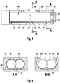
- the bore 29 is like the Figures 2 . 3 and 5 show integrated into the pump housing 15 and extends between the two screws 14, wherein the line 29 is partially disposed within a resting on both screws 14 tangential surface 35.
Landscapes
- Engineering & Computer Science (AREA)
- Mechanical Engineering (AREA)
- General Engineering & Computer Science (AREA)
- Applications Or Details Of Rotary Compressors (AREA)
- Compressors, Vaccum Pumps And Other Relevant Systems (AREA)
Description
- Die Erfindung betrifft ein Verfahren und eine Pumpenanordnung zum Evakuieren einer Kammer. Die Pumpenanordnung, die an die Kammer angeschlossen ist, umfasst eine Boosterpumpe und eine nachfolgende Vorpumpe. Eine solche Pumpenanordnung ist aus der
WO 2006/082366 bekannt. - In vielen technischen Anwendungen ist es heute gefordert, dass eine Kammer innerhalb kurzer Zeit auf ein vorgegebenes Vakuum evakuiert wird. Ein Beispiel sind Schleusenkammern, durch die Produkte in einen Vakuumraum eingeschleust werden. Bei den Produkten kann es sich beispielsweise um Massengüter wie Solarzellen, Displays usw. handeln, bei denen einzelne Fertigungsschritte in dem Vakuumraum durchgeführt werden. Solche Produkte sollen mit immer kürzeren Taktzeiten in den Vakuumraum eingeschleust werden. Es nicht ungewöhnlich, dass Schleusenkammern mit einem Volumen von einigen 100 l in deutlich unter 10 s auf einen Druck von weniger als 10-2 mbar evakuiert werden müssen.
- Man verwendet zum Evakuieren solcher Schleusenkammern meist Pumpenanordnungen aus zwei hintereinander geschalteten Pumpen, wobei die erste Pumpe üblicherweise als Boosterpumpe und die nachfolgende Pumpe als Vorpumpe bezeichnet wird. Die Hintereinanderschaltung zweier Pumpen ist deswegen zweckmäßig, weil nach dem Gasgesetz (Druck * Volumen = konstant; unter der Annahme konstanter Temperatur) die Vorpumpe für einen wesentlich kleineren Volumenstrom ausgelegt sein kann als die Boosterpumpe.
- Soll allerdings eine Schleusenkammer innerhalb sehr kurzer Zeit ausgehend von Atmosphärendruck evakuiert werden, so fördert die Boosterpumpe anfangs einen großen Volumenstrom bei hohem Druck, was zur Folge hat, dass auch am Ausgang der Boosterpumpe ein großer Volumenstrom ankommt. Vorpumpen, die einen derart großen Volumenstrom verarbeiten können, sind aufwändig und teuer.
- Der Erfindung liegt die Aufgabe zu Grunde, ein Verfahren und eine Pumpenanordnung vorzustellen, die das schnelle Evakuieren einer Kammer bei vermindertem apparativem Aufwand ermöglichen. Ausgehend vom eingangs genannten Stand der Technik wird die Aufgabe gelöst mit den Merkmalen der unabhängigen Ansprüche. Vorteilhafte Ausführungsformen finden sich in den Unteransprüchen.
- Bei dem erfindungsgemäßen Verfahren wird zunächst die Boosterpumpe bei geschlossenem Eingang beschleunigt. Gas aus der zu evakuierenden Kammer wird dann in die Boosterpumpe eingelassen, so dass der Boosterpumpe vorübergehend eine Übermaßleistung entnommen wird, die über die vom Antrieb der Boosterpumpe bereitgestellte Leistung hinausgeht. Das zum Ausgang der Boosterpumpe beförderte Gas wird durch ein Bypass-Ventil abgegeben, solange der Ausgangsdruck der Boosterpumpe oberhalb eines vorgegebenen Schwellwerts liegt. Das Gas wird an die Vorpumpe weitergeleitet, wenn der Ausgangsdruck der Boosterpumpe unterhalb des Schwellwerts abgesunken ist. Das von der Boosterpumpe zugeführte Gas wird mit der Vorpumpe komprimiert.
- Zunächst werden einige Begriffe erläutert. Mit den Begriffen Boosterpumpe und Vorpumpe wird die Reihenfolge der Pumpe in der Pumpenanordnung verdeutlicht. Eine Einschränkung im Hinblick auf die Ausgestaltung der Pumpe ist mit diesen Begriffen nicht verbunden.
- Die Erfindung hat erkannt, dass es durch das Beschleunigen der Boosterpumpe und die anschließende Entnahme der Übermaßleistung möglich wird, das Gas aus der Kammer unter so hohem Druck zum Ausgang der Boosterpumpe zu fördern, dass das Gas unter Umgehung der Vorpumpe direkt abgegeben werden kann. Erst wenn der Evakuierungsvorgang so weit fortgeschritten ist, dass die Boosterpumpe nicht mehr in der Lage ist, das Gas auf den entsprechenden Druck zu komprimieren, wird die Vorpumpe für die weitere Kompression hinzugenommen. Durch die Erfindung wird es möglich, die Vorpumpe nicht nur für einen kleineren Volumenstrom, sondern auch für einen kleineren Massestrom auszulegen als die Boosterpumpe.
- In aller Regel liegt am Ausgang des Bypass-Ventils Atmosphärendruck an. Der Schwellwert entspricht in diesem Fall dem Atmosphärendruck. Das Gas tritt also durch das Bypass-Ventil aus, solange der Ausgangsdruck der Boosterpumpe oberhalb des Atmosphärendrucks liegt. In der Spitze kann der Ausgangsdruck der Boosterpumpe um mindestens 1 bar, vorzugsweise mindestens 2 bar, weiter vorzugsweise mindestens 3 bar über Atmosphärendruck liegen. Das mit der Vorpumpe komprimierte Gas kann ebenfalls bei Atmosphärendruck an die Umgebung abgegeben werden.
- Zu Beginn des Evakuierungsvorgangs liegt in der Kammer regelmäßig Atmosphärendruck an, so dass der Evakuierungsvorgang bei Atmosphärendruck beginnt. Vor Beginn des Evakuierungsvorgangs ist der Eingang der Boosterpumpe geschlossen, so dass kein Gas aus der Kammer in die Boosterpumpe eintreten kann. Der Evakuierungsvorgang beginnt dann mit dem Zeitpunkt, zu dem Gas in die Boosterpumpe eingelassen wird.
- Um zu Beginn des Evakuierungsvorgangs einen großen Volumenstrom bei hohem Druck (z.B. Atmosphärendruck) fördern zu können, muss die Boosterpumpe eine große Verdichtungsleistung bereitstellen. Die große Verdichtungsleistung wird dadurch bereitgestellt, dass der Boosterpumpe während des Evakuierungsvorgangs vorübergehend mehr Verdichtungsleistung entnommen wird als der Antrieb der Boosterpumpe zur Verfügung stellt. Die über die Antriebsleistung hinausgehende Übermaßleistung wird der kinetischen Energie der Boosterpumpe entnommen. Die Boosterpumpe wird also abgebremst und die Drehzahl der Pumpe vermindert sich.
- Im Rahmen der Erfindung kann die in der Boosterpumpe entnommene Leistung sehr deutlich oberhalb der Antriebsleistung liegen. Möglich ist es beispielsweise, dass die Übermaßleistung in der Spitze mehr als 50 %, vorzugsweise mehr als 100 %, weiter vorzugsweise mehr als 200 % der Antriebsleistung beträgt. Bei einer Übermaßleistung von 100 % ist die Verdichtungsleistung doppelt so groß wie die Antriebsleistung.
- Es kann ferner vorgesehen sein, dass die Übermaßleistung nicht nur momentan, sondern über einen gewissen Zeitraum entnommen wird. Wenn der Evakuierungsvorgang zu dem Zeitpunkt beginnt, zu dem der Druck in der Kammer unter den Ausgangsdruck absinkt, und zu dem Zeitpunkt endet, zu dem der Enddruck in der Kammer erreicht ist, kann der Zeitraum, während dessen Übermaßleistung entnommen wird, beispielsweise über 10 %, vorzugsweise über 20 %, weiter vorzugsweise über 50 % des Evakuierungsvorgangs erstrecken. Die Drehzahl der Boosterpumpe kann sich durch die Entnahme der Übermaßleistung um mindestens 5 %, vorzugweise mindestens 10 %, weiter vorzugsweise mindestens 25 % Prozent reduzieren.
- Damit es möglich wird, der Pumpe Übermaßleistung in einem derartigen Umfang zu entnehmen, muss die Pumpe vor Beginn des Evakuierungsvorgangs in einen Zustand versetzt werden, in dem entsprechend viel kinetische Energie zur Verfügung steht. Die Pumpe wird deswegen vor Beginn des Evakuierungsvorgangs beschleunigt.
- Um genügend kinetische Energie zur Verfügung stellen zu können, ist die Drehzahl der Boosterpumpe zu Beginn des Evakuierungsvorgangs vorzugsweise höher als 8000 U/min, weiter vorzugsweise höher als 10.000 U/min, weiter vorzugsweise höher als 12.000 U/min. Der Durchmesser der in Drehung befindlichen Teile ist vorzugsweise größer als 5 cm, weiter vorzugsweise größer als 10 cm, weiter vorzugsweise größer als 20 cm.
- Wenn das Gas aus der Kammer bei im Wesentlichen Atmosphärendruck in die Boosterpumpe eingelassen wird, ist die Boosterpumpe einer schlagartigen Belastung ausgesetzt. Einige Pumpentypen, die bislang als Boosterpumpen verwendet werden, wie etwa Wälzkolbenpumpen, sind für die Aufnahme solcher schlagartigen Belastungen im Allgemeinen weniger geeignet. In einer vorteilhaften Ausführungsform wird als Boosterpumpe eine Schraubenpumpe verwendet, deren bevorzugte Gestaltung unten näher erläutert ist. Die Vorpumpe kann beispielsweise eine konventionelle Flüssigkeitsring-Vakuumpumpe sein.
- Mit dem erfindungsgemäßen Verfahren ist es möglich, eine Kammer mit einem Volumen von mehr als 100 l in weniger als 5 s von Atmosphärendruck auf einen Druck von weniger als 10-2 mbar zu evakuieren. Diese Möglichkeit ist von besonderem Interesse im Rahmen von Schleusenanwendungen, wo eine Schleusenkammer dieser Größenordnung mit kurzer Taktzeit immer wieder evakuiert werden muss. Am Eingang der Schleusenkammer liegt Atmosphärendruck an, was bedeutet, dass sich auch in der Schleusenkammer Atmosphärendruck einstellt, wenn der Eingang geöffnet wird, um ein Bauteil in die Schleusenkammer einzubringen. An den Ausgang der Schleusenkammer schließt sich ein Vakuumraum an, in dem der Druck beispielsweise bei 10-2 mbar liegt. Die Schleusenkammer muss also auf diesen Druck evakuiert werden, bevor der Ausgang geöffnet werden kann, um das Bauteil in den Vakuumraum zu übergeben.
- Beträgt beispielsweise die Taktzeit der Schleuse 10 s, so kann der Zeitraum, in dem der Boosterpumpe Übermaßleistung entnommen wird, beispielsweise 1 s betragen, während der Rest der Taktzeit genutzt wird, um die Boosterpumpe wieder auf die Ausgangsdrehzahl zu beschleunigen. Allgemeiner gesagt beträgt der Zeitraum der Entnahme von Übermaßleistung vorzugsweise mindestens 5 %, weiter vorzugsweise mindestens 10 % der Taktzeit. Während mindestens 30 %, vorzugsweise mindestens 50 %, weiter vorzugsweise mindestens 70 % der Taktzeit ist die der Boosterpumpe entnommene Leistung geringer als die Antriebsleistung, so dass die Boosterpumpe beschleunigt wird.
- Die Erfindung betrifft außerdem eine Pumpenanordnung. Die Pumpenanordnung umfasst eine Boosterpumpe und eine Vorpumpe, wobei der Ausgang der Boosterpumpe mit dem Eingang der Vorpumpe verbunden ist. Zwischen der Boosterpumpe und der Vorpumpe ist ein Bypass-Ventil angeordnet, durch das das mit der Boosterpumpe geförderte Gas unter Umgehung der Vorpumpe abgegeben werden kann. Die Pumpenanordnung umfasst außerdem eine Steuereinheit, die dazu ausgelegt ist, ein Steuersignal zu geben, wenn die Drehzahl der Boosterpumpe oberhalb eines vorgegebenen Drehzahlschwellwerts liegt. Der Drehzahlschwellwert ist so bemessen, dass die Boosterpumpe nach dem Überschreiten der betreffenden Drehzahl bereit ist für die Entnahme einer Übermaßleistung. Eine solche Pumpenanordnung ist geeignet, um eine Kammer gemäß dem erfindungsgemäßen Verfahren in kurzer Zeit zu evakuieren.
- Das Steuersignal kann übermittelt werden an eine Steuerung der zu evakuierenden Kammer, um mitzuteilen, dass die Boosterpumpe bereit ist für den nächsten Evakuierungsvorgang. Die Steuerung der Kammer kann daraufhin den Eingang der Boosterpumpe öffnen, über den die Boosterpumpe an die Kammer angeschlossen ist. Das Gas aus der Kammer tritt dann in die Boosterpumpe ein und die Kammer wird schnell evakuiert. Mit dem Eintritt des Gases in die Boosterpumpe erhöht sich die Last schlagartig, so dass die Drehzahl der Boosterpumpe sich vermindert.
- Die Steuereinheit der Boosterpumpe kann außerdem dazu ausgelegt sein, die Boosterpumpe vor Beginn des Evakuierungsvorgangs so zu beschleunigen, dass der Drehzahlschwellwert überschritten wird. Um eine hinreichende Menge von kinetischer Energie für die Entnahme der Übermaßleistung bereitzustellen, liegt der Drehzahlschwellwert vorzugsweise oberhalb der Förderdrehzahl der Boosterpumpe. Förderdrehzahl bezeichnet die Drehzahl, die sich als stationärer Zustand einstellt, wenn der Ansaugsdruck bei 100 mbar liegt. Die Antriebsleistung entspricht bei Förderdrehzahl der Pumpleistung, was bedeutet, dass die Drehzahl der Boosterpumpe konstant bleibt. Der Drehzahlschwellwert kann um 10 %, vorzugsweise um 30 %, weiter vorzugsweise um 50 % höher liegen als die Förderdrehzahl. In absoluten Zahlen kann der Drehzahlschwellwert beispielsweise mindestens 8000 U/min, vorzugsweise mindestens 10.000 U/min, weiter vorzugsweise mindestens 12.000 U/min betragen. Üblicherweise werden Boosterpumpen, die für eine Anwendung im Rahmen der Erfindung in Betracht kommen, mit wesentlich niedrigeren Drehzahlen betrieben. Eine Drehzahl von 6.000 U/min wird beim Betrieb solcher Boosterpumpen regelmäßig nicht überschritten. Auch bei dem erfindungsgemäßen Verfahren kann die Boosterpumpe über die Förderdrehzahl hinaus beschleunigt werden.
- Die erfindungsgemäße Anordnung kann außerdem die zu evakuierende Kammer umfassen. Die Steuereinheit der Anordnung kann dann dazu ausgelegt sein, den Eingang der Pumpe, über den die Boosterpumpe an die Kammer angeschlossen ist, zu öffnen, nachdem der Drehzahlschwellwert überschritten wurde. Ferner kann die Steuereinheit dazu ausgelegt sein, den Eingang geschlossen zu halten, während die Boosterpumpe beschleunigt wird.
- In einer vorteilhaften Ausführungsform wird als Boosterpumpe eine Schraubenpumpe verwendet, bei der die Schrauben zweier Gewinde so miteinander in Eingriff stehen, dass das Gas zwischen den Gewindegängen von einer Saugseite zu einer Druckseite gefördert wird. Um den angegebenen hohen Drehzahlen standhalten zu können, haben die Schrauben vorzugsweise jeweils zwei Gewinde, so dass die in Längsrichtung der Schrauben auftretenden Kräfte sich gegenseitig aufheben. Die Gewinde der Schraube sind vorzugsweise zweigängig ausgebildet. Dabei kann in Radialrichtung eine Punktsymmetrie der Schrauben derart bestehen, dass die Schrauben durch eine Drehung um die Längsachse um 180° in sich selbst abgebildet werden. Der Durchmesser der Schrauben ist vorzugsweise größer als 10 cm, weiter vorzugsweise größer als 15 cm, weiter vorzugsweise größer als 20 cm, so dass die Schrauben in Summe etwa die oben angegebene Masse haben.
- Damit die Schraubenpumpe den bei Boosterpumpen geforderten großen Volumenstrom aufnehmen kann, ist die Einlassöffnung vorzugsweise größer als 60 %, weiter vorzugsweise großer als 80 %, weiter vorzugsweise größer als 100 % der Querschnittsfläche einer Schraube. Um Leckverluste gering zu halten, ist nahe der Druckseite der radiale Abstand zwischen dem Gehäuse der Pumpe und dem Gewinde der Schraube möglichst klein (radialer Minimalabstand), beispielsweise kleiner als 0,2 mm, vorzugsweise kleiner als 0,1 mm.
- Im Einlassbereich, also insbesondere in dem Gehäuseabschnitt, in dem die Einlassöffnung ausgebildet ist, kann ein Saugspalt zwischen dem Gewinde der Schraube und dem Gehäuse bestehen, um einen hohen Volumenstrom in die Arbeitskammern der Pumpen hinein zu ermöglichen. Der radiale Durchmesser des Saugspalts ist vorzugsweise um den Faktor 50, weiter vorzugsweise den Faktor 100, weiter vorzugsweise den Faktor 200 größer als der radiale Minimalabstand. Der Saugspalt kann sich beispielsweise über einen Umfangswinkel von mindestens 15°, vorzugsweise mindestens 30° des Gehäuses erstrecken. In Längsrichtung kann der Saugspalt sich über mindestens 20 %, vorzugsweise mindestens 30 %, weiter vorzugsweise mindestens 40 % der Länge eines Gewindes der Schraube erstrecken. Vorzugsweise entspricht die Länge des Saugspalts der Länge einer 360°-Windung des Gewindes in diesem Bereich. Das Gewinde hat im Einlassbereich also eine sehr große Steigung. Die erste 360°-Windung kann sich beispielsweise über mindestens 20%, vorzugsweise mindestens 30%, weiter vorzugsweise mindestens 40% der Länge des Gewindes erstrecken. Insgesamt umfasst jeder Gewindegang des zweigängigen Gewindes vorzugsweise mindestens drei, weiter vorzugsweise mindestens vier vollständige 360°-Windungen.
- Die Erfindung wird nachfolgend unter Bezugnahme auf die beigefügten Zeichnungen anhand vorteilhafter Ausführungsform beispielhaft beschrieben. Es zeigen:
- Fig. 1:
- eine erfindungsgemäße Pumpenanordnung, die an eine Schleusenkammer angeschlossen ist.
- Fig. 2:
- eine perspektivische, teilweise weggebrochene Darstellung einer für die erfindungsgemäße Anordnung geeigneten Schraubenpumpe;
- Fig. 3:
- einen Ausschnitt der Pumpe aus
Fig. 1 in vergrößerter Darstellung; - Fig. 4:
- die Ansicht aus
Fig. 3 in einem anderen Zustand der Pumpe; - Fig. 5:
- eine schematische Querschnittsansicht einer für die erfindungsgemäße Anordnung geeigneten Schraubenpumpe entlang der Achse einer Schraube; und
- Fig. 6A/B:
- Schnitte entlang den Linien A-A und B-B in
Fig. 5 . - In einem in
Fig. 1 gezeigten Vakuumraum 40 werden bestimmte Verfahrensschritte an einem Produkt 41 vorgenommen. Bei dem vereinfacht in Blockform dargestellten Produkt 41 kann es sich beispielsweise um eine Vielzahl von Halbleiterbauelementen, wie etwa Solarzellen oder Displays handeln. Der Verfahrensschritt kann ein Beschichtungsvorgang sein. Für den Verfahrensschritt ist es erforderlich, dass der Druck in dem Vakuumraum 40 unterhalb von 0,5 mbar liegt. Um den Vakuumraum auf diesem Druck zu halten, ist eine inFig. 1 nicht dargestellte Vakuumpumpe an den Vakuumraum 40 angeschlossen. - An den Vakuumraum 40 schließt sich eine Schleuse mit einer Schleusenkammer 42 an, durch die das Produkt 41 in die Vakuumkammer eingebracht wird. Die Schleusenkammer 42 hat eine Eingangsöffnung und eine Ausgangsöffnung, die mit Schiebetüren 43, 44 versehen sind. Die Schiebetüren 43, 44 sind durch eine Steuerung 50 so gesteuert, dass zu keinem Zeitpunkt beide zugleich geöffnet sind. Wenn die Schiebetür 43 geöffnet ist, liegt in der Schleusenkammer 42 Atmosphärendruck an. Die Schleuse hat ein Volumen von beispielsweise 200 l.
- Bei geöffneter Schiebetür 43 kann mithilfe von Laufbändern 45 das Produkt 41 in die Schleusenkammer 42 eingefahren werden. Nachdem die Schiebetür 43 anschließend wieder verschlossen ist, wird die Schleusenkammer 42 durch eine an die Schleusenkammer 42 angeschlossenen Pumpenanordnung evakuiert, so dass der Druck in der Schleusenkammer 42 dem in dem Vakuumraum 40 anliegenden Druck von weniger als 0,5 mbar entspricht. Nach Abschluss des Evakuierungsvorgangs wird die Schiebetür 44 geöffnet und das Produkt 41 mit den Laufbändern 45 in den Vakuumraum 40 eingefahren. Anschließend wird die Schiebetür 44 wieder verschlossen, die Schleusenkammer 42 auf Atmosphärendruck gebracht und die Schiebetür 43 geöffnet. Damit ist ein Zyklus in der Schleuse abgeschlossen. Die Taktzeit des Zyklus liegt bei etwa 10 s.
- Für den eigentlichen Evakuierungsvorgang, durch den der Druck in der Schleusenkammer ausgehend von Atmosphärendruck auf einen Enddruck von weniger als 0,5 mbar reduziert wird, steht eine Zeitspanne zur Verfügung, die deutlich unterhalb der Taktzeit liegt. Beispielsweise kann der Evakuierungsvorgang sich über einen Zeitraum von 5 s erstrecken.
- Um eine Schleuse dieses Volumens in derart kurzer Zeit evakuieren zu können, ist eine leistungsfähige Pumpenanordnung erforderlich, die insbesondere in dem gesamten Druckbereich zwischen Atmosphärendruck und Enddruck ein hohes Saugvermögen aufweist. Dies leistet die erfindungsgemäße Pumpenanordnung, in der gemäß
Fig. 1 eine Schraubenpumpe als Boosterpumpe 46 und eine Flüssigkeitsring-Vakuumpumpe als Vorpumpe 47 hintereinander geschaltet sind. Die Flüssigkeitsring-Vakuumpumpe ist konventionell gestaltet, so dass eine detaillierte Beschreibung nicht erforderlich ist. - Um den Evakuierungsvorgang zu starten, wird die Boosterpumpe 46 zunächst auf eine Drehzahl beschleunigt, die deutlich oberhalb der Förderdrehzahl liegt. Ein zwischen der Boosterpumpe 46 und der Schleusenkammer 42 angeordnetes Ventil 48 ist geschlossen, so dass kein Gas aus der Schleusenkammer 42 in den Eingang der Boosterpumpe 46 eintreten kann. Die Boosterpumpe 46 steht also nicht unter Last, so dass eine vergleichsweise geringe Antriebsleistung ausreicht, um die Boosterpumpe 46 zu beschleunigen.
- Ist die Boosterpumpe 46 so weit beschleunigt, dass ein vorgegebener Drehzahlschwellwert überschritten wird, sendet eine Steuereinheit 16 der Boosterpumpe 46 ein Steuersignal an die Steuerung 50 der Schleusenkammer. Die Steuerung 50 erhält damit die Information, dass die Boosterpumpe 46 bereit ist für den nächsten Evakuierungsvorgang. Sobald auch die Schleusenkammer 42 für den nächsten Evakuierungsvorgang bereit ist, kann die Steuerung 50 das Ventil 48 öffnen, so dass die Boosterpumpe 46 Luft aus der Schleusenkammer 42 ansaugen kann. Die Luft wird durch die Boosterpumpe 46 gefördert und dabei komprimiert, so dass am Ausgang der Boosterpumpe 46 ein Druck anliegt, der deutlich oberhalb des Atmosphärendrucks liegt. In der Spitze kann am Ausgang der Boosterpumpe 46 beispielsweise ein Druck von 3 bar oberhalb des Atmosphärendrucks anliegen.
- Zwischen der Vorpumpe 47 und der Boosterpumpe 46 ist ein Bypass-Ventil 49 angeordnet, an dessen Ausgang Atmosphärendruck anliegt. Das Bypass-Ventil 49 ist als Überdruckventil ausgestaltet, so dass das komprimierte Gas vom Ausgang der Boosterpumpe 46 automatisch über das Bypass-Ventil 49 austritt, solange der Druck am Ausgang der Boosterpumpe 46 oberhalb von Atmosphärendruck liegt. Sinkt der Druck am Ausgang der Boosterpumpe 46 unter Atmosphärendruck, schließt das Bypass-Ventil 49. Das Gas wird dann von der Vorpumpe 47 übernommen und so weiter komprimiert, dass es bei Atmosphärendruck an die Umgebung abgegeben werden kann.
- Je weiter der Druck in der Schleusenkammer 42 sich dem Enddruck annähert, desto niedriger wird auch der Druck zwischen der Boosterpumpe 46 und der Vorpumpe 47. Die Vorpumpe 47 ist so ausgelegt, dass sie das Gas ausgehend von diesem Druck auf Atmosphärendruck komprimieren kann.
- Besonderen Belastungen ist bei einem solchen Evakuierungsvorgang die Boosterpumpe 46 ausgesetzt. Wenn das Ventil 48 geöffnet wird, verursacht der in die Boosterpumpe 46 eintretende Luftstrom eine schlagartige Belastung. Außerdem wird der Boosterpumpe 46 durch das Eintreten eines großen Volumenstroms bei Atmosphärendruck eine hohe Verdichtungsleistung abgefordert. Diese Verdichtungsleistung übersteigt die Antriebsleistung der Boosterpumpe 46, was bedeutet, dass der Boosterpumpe 46 eine Übermaßleistung entnommen wird. Die Übermaßleistung wird aus der kinetischen Rotationsenergie der Boosterpumpe 46 gewonnen, was gleichbedeutend damit ist, dass die Drehzahl der Boosterpumpe 46 sich in dieser Phase vermindert.
- Um genügend kinetische Rotationsenergie bereitstellen zu können, wird die Boosterpumpe 46 vor Beginn des Evakuierungsvorgangs auf eine hohe Drehzahl von mehr als 10.000 U/min beschleunigt. Durch die Entnahme der Übermaßleistung vermindert sich die Drehzahl innerhalb von 1 s auf 9000 U/min. Die verbleibende Taktzeit wird genutzt, um die Boosterpumpe 46 wieder auf die ursprüngliche Drehzahl zu beschleunigen. Die Antriebsleistung liegt in dieser Phase folglich höher als die der Boosterpumpe 46 entnommene Verdichtungsleistung.
- Eine Boosterpumpe 46, die einerseits den Belastungen zu Beginn des Evakuierungsvorgangs standhält und andererseits über den gesamten Druckbereich das erforderliche Saugvermögen aufweist, ist nachfolgend beschrieben.
- Die als Boosterpumpe geeignete Schraubenpumpe umfasst gemäß
Fig. 2 zwei Schrauben 14, die in einem Pumpengehäuse 15 aufgenommen sind. Eine der Schrauben 14 ist aufgrund des nicht vollständig dargestellten Pumpengehäuses 15 über die gesamte Länge sichtbar, während die andere Schraube 14 zu wesentlichen Teilen von dem Pumpengehäuse 15 verdeckt ist. Die beiden Schrauben 14 stehen in Eingriff miteinander, was bedeutet, dass die Gewindevorsprünge der einen Schraube 14 in die Vertiefung zwischen zwei Gewindevorsprüngen der anderen Schraube 14 eingreifen. - Die Pumpe umfasst eine Steuer- und Antriebseinheit 16, in der für jede der Schrauben 14 ein elektronisch gesteuerter Antriebsmotor 17 angeordnet ist. Die elektronische Steuerung der Antriebsmotoren 17 ist so eingerichtet, dass die beiden Schrauben 14 vollständig synchron zueinander laufen, ohne dass die Gewindevorsprünge der Schrauben 14 sich berühren. Als zusätzliche Sicherheit gegen Schäden an den Schrauben 14 sind die beiden Schrauben 14 jeweils mit einem Zahnrad 18 ausgestattet. Die Zahnräder 18 stehen in Eingriff miteinander und bewirken eine Zwangskopplung der beiden Schrauben 14 für den Fall, dass die elektronische Synchronisation der Schrauben 14 ausfällt.
- Jede Schraube 14 ist mit zwei Gewinden 19 ausgestattet, so dass die Pumpe insgesamt vier Gewinde 19 aufweist. Die Gewinde 19 erstrecken sich jeweils von einer Saugseite 20 im Zentrum der Schraube 14 zu einer Druckseite 21 an den äußeren Enden der Schraube 14. Die beiden Gewinde einer Schraube 14 sind gegenläufig ausgerichtet, so dass sie von der Saugseite 20 zu der Druckseite 21 hin arbeiten.
- Jedes der Gewinde 19 umfasst einen ersten Gewindegang 22 und einen zweiten Gewindegang 23. Die Gewinde 19 sind also zweigängig in dem Sinne, dass die Gewindegänge 22, 23 miteinander verschränkt sind, so dass sie zusammen eine doppelhelixartige Form bilden. Die beiden Gewindegänge 22, 23 sind so geformt, dass die Gewinde 19 in Radialrichtung symmetrisch sind. Betrachtet man die Schraube 14 von der Druckseite des ersten Gewindes 19 bis zur Druckseite des zweiten Gewindes 19, so hat die Schraube 14 außerdem eine Symmetrie in Längsrichtung.
- Die Gewinde 19 sind so gestaltet, dass im Bereich der Saugseite 20 ein größeres Volumen zwischen zwei benachbarten Gewindevorsprüngen eingeschlossen ist als im Bereich der Druckseite 21. Das Volumen der Arbeitskammern, das dem zwischen den Gewindevorsprüngen eingeschlossenen Volumen entspricht, reduziert sich also von der Saugseite zur Druckseite, so dass in der Arbeitskammer enthaltenes Gas auf dem Weg von der Saugseite zur Druckseite komprimiert wird.
- Das Gehäuse 15 der Pumpe ist mit einer Eingangsöffnung 24 versehen, die so angeordnet ist, dass sie Zugang zu den Saugseiten 20 aller vier Gewinde 19 bietet. Um einen großen Volumenfluss in die Pumpe hinein zu ermöglichen, hat die Eingangsöffnung 24 einen großen Querschnitt. Im Ausführungsbeispiel ist die Querschnittsfläche der Eintrittsöffnung 24 größer als die von einer Schraube 14 aufgespannte kreisförmige Kontur.
- Um den Volumenfluss in die Arbeitskammern hinein weiter zu verbessern, ist am Gehäuse 15 der Pumpe ein Saugspalt 25 ausgebildet, der sich an die Eingangsöffnung 24 anschließt und der Kontur der Schraube 14 in Umfangsrichtung folgt. In Längsrichtung erstreckt sich der Saugspalt 25 etwa über die Hälfte der Länge des Gewindes 19 zwischen der Saugseite 20 und der Druckseite 21. In Umfangsrichtung variiert die Abmessung des Saugspalts 25 mit der Eingangsöffnung, je weiter sich die Eingangsöffnung 24 an der betreffenden Stelle zur Seite erstreckt, desto kürzer ist die Erstreckung des Saugspalts 25 in Umfangsrichtung an dieser Stelle. An der breitesten Stelle der Eingangsöffnung 24 erstreckt der Saugspalt 25 sich über einen Umfangswinkel von etwa 45°. In dem Bereich, in dem die Eingangsöffnung 24 den Saugspalt 25 nicht mehr überdeckt, erstreckt der Saugspalt 24 sich über einen Umfangswinkel von etwa 120°. Die Abmessung des Saugspalts 25 in Radialrichtung entspricht dem Abstand zwischen dem Pumpengehäuse 15 und der Kontur der Schraube 14 in diesem Bereich. Dieser Abstand liegt in der Größenordnung von etwa 10 mm.
- Durch den Saugspalt ist das Gas nicht darauf beschränkt, in Radialrichtung in die Arbeitskammern einzutreten, sondern das Gas kann sich auch über einen Gewindevorsprung hinweg durch den Saugspalt hindurch in die Arbeitskammer hinein bewegen. Der Volumenstrom in die Arbeitskammer hinein wird dadurch weiter vergrößert.
- Ein weiterer Beitrag zur Vergrößerung des Volumenstroms in die Arbeitskammer hinein wird dadurch erreicht, dass zwischen der Saugseite 20 des ersten Gewindes 19 einer Schraube 14 und der Saugseite 20 des zweiten Gewindes 19 der Schraube 14 ein Abstand besteht. Dadurch bleibt im Zentrum der Schraube 14 Platz frei, durch den das Gas auch in radialer Richtung in die Arbeitskammer eintreten kann.
- Der Bereich, in dem sich der Saugspalt 25 erstreckt (= erster Gehäuseabschnitt 26), dient der Befüllung der Arbeitskammern. In dem sich daran anschließenden zweiten Gehäuseabschnitt 27 ist der Abstand zwischen dem Gehäuse und der Kontur der Schraube 14 so klein wie es technisch möglich ist (radialer Minimalabstand). Im zweiten Gehäuseabschnitt findet die Kompression statt und ein Leckfluss von einer Arbeitskammer in die nächste Arbeitskammer ist unerwünscht.
- Am Übergang vom ersten Gehäuseabschnitt 26 zum zweiten Gehäuseabschnitt 27 ist eine Übergangskante 28 ausgebildet. Die Übergangskante 28 erstreckt sich in Umfangsrichtung über den gesamten Saugspalt 25 und definiert den Übergang vom Saugspalt 25 zu dem zweiten Gehäuseabschnitt 27, in dem der radiale Minimalabstand zwischen dem Gehäuse 15 und der Schraube 14 besteht.
- Die Kompression beginnt, sobald die Arbeitskammer in den zweiten Gehäuseabschnitt übergegangen ist, sobald also der Gewindevorsprung, der die Arbeitskammer zur Saugseite hin begrenzt, mit der Übergangskante 28 abgeschlossen hat. Die Übergangskante 28 ist so angeordnet, dass der Abschluss zwischen dem Gewindevorsprung und der Übergangskante 28 zu einem Zeitpunkt stattfindet, zu dem die Arbeitskammer noch ihr maximales Volumen hat.
- In Umfangsrichtung betrachtet schließt die Übergangskante 28 einen Winkel mit der Querrichtung ein, der kleiner ist als die Steigung des Gewindevorsprungs, der mit der Übergangskante 28 abschließt. Dadurch wird erreicht, dass der Abschluss zwischen dem Gewindevorsprung und der Übergangskante 28 nicht schlagartig erfolgt, sondern sich über eine kurze Zeitspanne erstreckt. Dadurch reduziert sich das Betriebsgeräusch der Pumpe.
- Die eigentliche Volumenkompression findet in einem kurzen Abschnitt des Gewindes unmittelbar nach dem Abschluss der Arbeitskammer statt. Die sich daran anschließenden weiteren Windungen des Gewindes dienen der Abdichtung und bewirken noch eine thermodynamische Kompression.
- Auf der Druckseite 21 des Gewindes 19 wird das Gas aus der Arbeitskammer abgegeben. Durch eine Bohrung 29 in dem Pumpengehäuse 15 wird das komprimierte Gas von den außen liegenden Druckseiten 21 zu einer zentralen Auslassöffnung zusammengeführt. Die Auslassöffnung, die in den Figuren nicht sichtbar ist, ist der Einlassöffnung 24 gegenüber angeordnet. Die Bohrung 29 ist, wie die
Figuren 2 ,3 und5 zeigen, in das Pumpengehäuse 15 integriert und erstreckt sich zwischen den beiden Schrauben 14, wobei die Leitung 29 teilweise innerhalb einer auf beiden Schrauben 14 aufliegenden Tangentialfläche 35 angeordnet ist.
Claims (14)
- Verfahren zum Evakuieren einer Kammer (42), wobei eine Pumpenanordnung aus einer Boosterpumpe (46) und einer nachfolgenden Vorpumpe (47) an die Kammer (42) angeschlossen ist, mit folgenden Schrittena. Beschleunigen der Boosterpumpe (46) bei geschlossenem Eingang der Boosterpumpe (46);b. Einlassen des Gases aus der Kammer (42) in die Boosterpumpe (46), so dass der Boosterpumpe (46) vorübergehend eine Übermaßleistung entnommen wird, die über die von dem Antrieb (17) der Boosterpumpe (46) bereitgestellte Leistung hinausgeht; undc. Fördern des Gases zum Ausgang der Boosterpumpe (46), wobeii. das Gas durch ein Bypass-Ventil (49) abgegeben wird, solange der Ausgangsdruck der Boosterpumpe (46) oberhalb eines vorgegebenen Schwellwerts liegt;ii. das Gas an die Vorpumpe (47) weitergeleitet wird, wenn der Ausgangsdruck der Boosterpumpe (46) unterhalb den Schwellwert abgesunken ist;d. Komprimieren des von der Boosterpumpe (46) zugeführten Gases mit der Vorpumpe (47).
- Verfahren nach Anspruch 1, dadurch gekennzeichnet, dass die Übermaßleistung in der Spitze mindestens 50 %, vorzugsweise mindestens 100 %, weiter vorzugsweise mindestens 200 % der Antriebsleistung beträgt.
- Verfahren nach Anspruch 1 oder 2, dadurch gekennzeichnet, dass die Übermaßleistung während mindestens 10 %, vorzugsweise mindestens 20 %, weiter vorzugsweise mindestens 50 % des Evakuierungsvorgangs entnommen wird.
- Verfahren nach einem der Ansprüche 1 bis 3, dadurch gekennzeichnet, dass die Drehzahl der Boosterpumpe (46) zu Beginn des Evakuierungsvorgangs größer als 8000 U/min, vorzugsweise größer als 10.000 U/min, weiter vorzugsweise größer als 12.000 U/min ist.
- Verfahren nach einem der Ansprüche 1 bis 4, dadurch gekennzeichnet, dass der Ausgangsdruck der Boosterpumpe (46) in der Spitze um mindestens 1 bar, vorzugsweise mindestens 2 bar, weiter vorzugsweise mindestens 3 bar über Atmosphärendruck liegt.
- Verfahren nach einem der Ansprüche 1 bis 5, dadurch gekennzeichnet, dass die Kammer eine Schleusenkammer (42) ist, die mit einer Taktzeit von weniger als 15 s, vorzugsweise weniger als 10 s betrieben wird.
- Verfahren nach Anspruch 6, dadurch gekennzeichnet, dass der Boosterpumpe während mindestens 5 %, vorzugsweise mindestens 10 % der Taktzeit der Schleusenkammer (42) Übermaßleistung entnommen wird.
- Pumpenanordnung mit einer Boosterpumpe (46) und einer Vorpumpe (47), wobei der Ausgang der Boosterpumpe (46) mit dem Eingang der Vorpumpe (47) verbunden ist, wobei zwischen der Boosterpumpe (46) und der Vorpumpe (47) ein Bypass-Ventil (49) angeordnet ist, durch das mit der Boosterpumpe (46) gefördertes Gas unter Umgehung der Vorpumpe (47) abgegeben werden kann, dadurch gekennzeichnet, dass eine Steuereinheit (16) dazu ausgelegt ist, ein Steuersignal zu geben, wenn die Drehzahl der Boosterpumpe (46) oberhalb eines vorgegebenen Drehzahlschwellwerts liegt, so dass die Boosterpumpe (46) für die Entnahme einer Übermaßleistung bereit ist.
- Pumpenanordnung nach Anspruch 8, dadurch gekennzeichnet, dass der Drehzahlschwellwert höher ist als die Förderdrehzahl der Pumpe, vorzugsweise um wenigstens 30% höher, weiter vorzugsweise um wenigstens 50% höher.
- Pumpenanordnung nach Anspruch 8 oder 9, dadurch gekennzeichnet, dass der Drehzahlschwellwert höher ist als 8000 U/min, vorzugsweise höher ist als 10.000 U/min, weiter vorzugsweise höher ist als 12.000 U/min.
- Pumpenanordnung nach einem der Ansprüche 8 bis 10, dadurch gekennzeichnet, dass die Boosterpumpe (46) eine Schraubenpumpe ist.
- Pumpenanordnung nach Anspruch 11, dadurch gekennzeichnet, dass die Schrauben (14) der Schraubenpumpe jeweils zwei Gewinde aufweisen.
- Pumpenanordnung nach einem der Ansprüche 8 bis 12, dadurch gekennzeichnet, dass ein Gehäuse (15) vorgesehen ist, in dem die Schrauben (14) aufgenommen sind, und dass das Gehäuse (15) so gestaltet ist, dass es im Bereich eines Gewindes (19) einen ersten Gehäuseabschnitt (26) und einen zweiten Gehäuseabschnitt (27) aufweist, wobei in dem ersten Gehäuseabschnitt (26) ein Saugspalt (25) zwischen dem Gehäuse (15) und dem Gewinde (19) besteht und wobei in dem zweiten Gehäuseabschnitt (27) ein radialer Minimalabstand zwischen dem Gehäuse (15) und dem Gewinde (19) besteht.
- Pumpenanordnung nach Anspruch 13, dadurch gekennzeichnet, dass das Gehäuse (15) mit einer Eingangsöffnung (24) versehen ist und dass die Eingangsöffnung (24) größer ist als 60 %, vorzugsweise 80 %, weiter vorzugsweise 100 % der Querschnittsfläche des Gewindes (19) .
Priority Applications (1)
| Application Number | Priority Date | Filing Date | Title |
|---|---|---|---|
| EP13727952.7A EP2867533B1 (de) | 2012-06-28 | 2013-06-12 | Verfahren und pumpenanordnung zum evakuieren einer kammer |
Applications Claiming Priority (3)
| Application Number | Priority Date | Filing Date | Title |
|---|---|---|---|
| EP12174031 | 2012-06-28 | ||
| PCT/EP2013/062179 WO2014001090A1 (de) | 2012-06-28 | 2013-06-12 | Verfahren und pumpenanordnung zum evakuieren einer kammer |
| EP13727952.7A EP2867533B1 (de) | 2012-06-28 | 2013-06-12 | Verfahren und pumpenanordnung zum evakuieren einer kammer |
Publications (2)
| Publication Number | Publication Date |
|---|---|
| EP2867533A1 EP2867533A1 (de) | 2015-05-06 |
| EP2867533B1 true EP2867533B1 (de) | 2019-01-16 |
Family
ID=48579129
Family Applications (1)
| Application Number | Title | Priority Date | Filing Date |
|---|---|---|---|
| EP13727952.7A Active EP2867533B1 (de) | 2012-06-28 | 2013-06-12 | Verfahren und pumpenanordnung zum evakuieren einer kammer |
Country Status (6)
| Country | Link |
|---|---|
| US (1) | US11215180B2 (de) |
| EP (1) | EP2867533B1 (de) |
| KR (1) | KR101995358B1 (de) |
| CN (1) | CN104302922B (de) |
| TW (1) | TWI630324B (de) |
| WO (1) | WO2014001090A1 (de) |
Families Citing this family (8)
| Publication number | Priority date | Publication date | Assignee | Title |
|---|---|---|---|---|
| DE102015116965B4 (de) | 2015-10-06 | 2024-05-08 | VON ARDENNE Asset GmbH & Co. KG | Kammeranordnung und Verfahren |
| FR3054005B1 (fr) * | 2016-07-13 | 2018-08-24 | Pfeiffer Vacuum | Procede de descente en pression dans un sas de chargement et de dechargement et groupe de pompage associe |
| JP6725389B2 (ja) * | 2016-09-28 | 2020-07-15 | キオクシア株式会社 | 半導体製造装置 |
| CN106524558B (zh) * | 2016-11-10 | 2023-09-29 | 青岛海尔中央空调有限公司 | 一种基于三级离心式压缩机的多联机热泵系统 |
| DE202016007609U1 (de) | 2016-12-15 | 2018-03-26 | Leybold Gmbh | Vakuumpumpsystem |
| DE102017209782A1 (de) * | 2017-06-09 | 2018-12-13 | Evonik Degussa Gmbh | Verfahren zur Wärmedämmung eines evakuierbaren Behälters |
| CN110578690B (zh) * | 2019-10-21 | 2024-10-29 | 无锡锡压压缩机有限公司 | 一种两级螺杆空气压缩机的级间压力调节结构 |
| GB2623356B (en) * | 2022-10-14 | 2025-01-08 | Edwards Ltd | Scroll pump |
Citations (7)
| Publication number | Priority date | Publication date | Assignee | Title |
|---|---|---|---|---|
| EP0343914A1 (de) | 1988-05-24 | 1989-11-29 | The Boc Group, Inc. | Vorrichtung und Verfahren zur Erzeugung eines Vakuums |
| DE19748385A1 (de) | 1997-11-03 | 1999-05-06 | Peter Frieden | Trockenlaufender Schraubenverdichter oder Vakuumpumpe |
| US6004109A (en) | 1995-07-06 | 1999-12-21 | Balzers Und Leybold Deutschland Holding Ag | Apparatus for the rapid evacuation of a vacuum chamber |
| WO2006082366A1 (en) | 2005-02-02 | 2006-08-10 | Edwards Limited | Method of operating a pumping system |
| JP2010121538A (ja) | 2008-11-19 | 2010-06-03 | Toyota Industries Corp | 真空ポンプ装置 |
| JP2010138725A (ja) | 2008-12-09 | 2010-06-24 | Toyota Industries Corp | 真空ポンプ装置 |
| US20110293459A1 (en) | 2010-05-17 | 2011-12-01 | Kirkland Timothy M | Screw pump with field refurbishment provisions |
Family Cites Families (11)
| Publication number | Priority date | Publication date | Assignee | Title |
|---|---|---|---|---|
| JP2515831B2 (ja) * | 1987-12-18 | 1996-07-10 | 株式会社日立製作所 | スクリユ―真空ポンプ |
| FR2647853A1 (fr) * | 1989-06-05 | 1990-12-07 | Cit Alcatel | Pompe primaire seche a deux etages |
| JP3501524B2 (ja) * | 1994-07-01 | 2004-03-02 | 東京エレクトロン株式会社 | 処理装置の真空排気システム |
| US5944049A (en) * | 1997-07-15 | 1999-08-31 | Applied Materials, Inc. | Apparatus and method for regulating a pressure in a chamber |
| WO2002033262A1 (en) | 2000-10-18 | 2002-04-25 | Leybold Vakuum Gmbh | Multi-stage helical screw rotor |
| JP2004197644A (ja) * | 2002-12-18 | 2004-07-15 | Toyota Industries Corp | 真空ポンプの制御装置 |
| GB0402330D0 (en) * | 2004-02-03 | 2004-03-10 | Boc Group Plc | A pumping system |
| GB0418771D0 (en) * | 2004-08-20 | 2004-09-22 | Boc Group Plc | Evacuation of a load lock enclosure |
| TWI467092B (zh) * | 2008-09-10 | 2015-01-01 | Ulvac Inc | 真空排氣裝置 |
| JP2010151538A (ja) | 2008-12-24 | 2010-07-08 | Toyota Motor Corp | 歯面測定基準設定装置および歯面測定基準設定方法 |
| FR2952683B1 (fr) | 2009-11-18 | 2011-11-04 | Alcatel Lucent | Procede et dispositif de pompage a consommation d'energie reduite |
-
2013
- 2013-06-12 WO PCT/EP2013/062179 patent/WO2014001090A1/de not_active Ceased
- 2013-06-12 KR KR1020147030994A patent/KR101995358B1/ko active Active
- 2013-06-12 EP EP13727952.7A patent/EP2867533B1/de active Active
- 2013-06-12 US US14/408,995 patent/US11215180B2/en active Active
- 2013-06-12 CN CN201380025545.1A patent/CN104302922B/zh active Active
- 2013-06-26 TW TW102122720A patent/TWI630324B/zh active
Patent Citations (7)
| Publication number | Priority date | Publication date | Assignee | Title |
|---|---|---|---|---|
| EP0343914A1 (de) | 1988-05-24 | 1989-11-29 | The Boc Group, Inc. | Vorrichtung und Verfahren zur Erzeugung eines Vakuums |
| US6004109A (en) | 1995-07-06 | 1999-12-21 | Balzers Und Leybold Deutschland Holding Ag | Apparatus for the rapid evacuation of a vacuum chamber |
| DE19748385A1 (de) | 1997-11-03 | 1999-05-06 | Peter Frieden | Trockenlaufender Schraubenverdichter oder Vakuumpumpe |
| WO2006082366A1 (en) | 2005-02-02 | 2006-08-10 | Edwards Limited | Method of operating a pumping system |
| JP2010121538A (ja) | 2008-11-19 | 2010-06-03 | Toyota Industries Corp | 真空ポンプ装置 |
| JP2010138725A (ja) | 2008-12-09 | 2010-06-24 | Toyota Industries Corp | 真空ポンプ装置 |
| US20110293459A1 (en) | 2010-05-17 | 2011-12-01 | Kirkland Timothy M | Screw pump with field refurbishment provisions |
Also Published As
| Publication number | Publication date |
|---|---|
| US20150152871A1 (en) | 2015-06-04 |
| EP2867533A1 (de) | 2015-05-06 |
| US11215180B2 (en) | 2022-01-04 |
| WO2014001090A1 (de) | 2014-01-03 |
| CN104302922A (zh) | 2015-01-21 |
| KR101995358B1 (ko) | 2019-07-02 |
| TW201410977A (zh) | 2014-03-16 |
| KR20150027045A (ko) | 2015-03-11 |
| TWI630324B (zh) | 2018-07-21 |
| CN104302922B (zh) | 2017-08-08 |
Similar Documents
| Publication | Publication Date | Title |
|---|---|---|
| WO2014001090A1 (de) | Verfahren und pumpenanordnung zum evakuieren einer kammer | |
| EP3161320B1 (de) | Seitenkanalpumpe | |
| DE19530662A1 (de) | Schraubenvakuumpumpe | |
| EP2867532B1 (de) | Schraubenpumpe | |
| EP2791511B1 (de) | Flüssigkeitsring-vakuumpumpe mit kavitationsregelung | |
| CH679237A5 (de) | ||
| DE102012204403A1 (de) | Radialverdichtereinheit | |
| DE3722164C2 (de) | Turbomolekularpumpe | |
| DE10150015A1 (de) | Mehrkammeranlage zur Behandlung von Gegenständen unter Vakuum, Verfahren zur Evakuierung dieser Anlage und Evakuierungssystem dafür | |
| EP4108931A1 (de) | Molekularvakuumpumpe mit verbessertem saugvermögen sowie verfahren zum betreiben einer molekularvakuumpumpe zur erzielung eines verbesserten saugvermögens | |
| DE69928172T2 (de) | Vacuumpumpe | |
| EP3112688B2 (de) | Splitflow-vakuumpumpe sowie vakuum-system mit einer splitflow-vakuumpumpe | |
| EP3827170B1 (de) | Fluidfördereinrichtung | |
| EP3394449B1 (de) | Kältemittelverdichteranlage | |
| EP3311028B1 (de) | Verfahren zum verdichten eines gases, recheneinheit und mehrstufiger kolbenverdichter | |
| DE102015218679A1 (de) | Schraubenspindelpumpe | |
| WO2013023954A2 (de) | Wälzkolbenpumpe | |
| EP3080458B1 (de) | Verdichter | |
| EP3158198B1 (de) | Flüssigkeitsring-verdichtungsmaschine | |
| DE102017201342A1 (de) | Wellenanordnung | |
| DE3526517A1 (de) | Turbomolekularpumpe | |
| DE2329799A1 (de) | Verfahren und vorrichtung zur schmierung der lager der rotoren von schraubenkompressoren | |
| EP3859159B1 (de) | Schraubenverdichter | |
| WO2018228784A1 (de) | Mehrstufige wälzkolbenpumpe | |
| EP3064775B1 (de) | Vakuumpumpe sowie Verfahren zur Detektion eines Kontaktes zwischen wenigstens einem Rotor und einem Stator einer Vakuumpumpe |
Legal Events
| Date | Code | Title | Description |
|---|---|---|---|
| PUAI | Public reference made under article 153(3) epc to a published international application that has entered the european phase |
Free format text: ORIGINAL CODE: 0009012 |
|
| 17P | Request for examination filed |
Effective date: 20141128 |
|
| AK | Designated contracting states |
Kind code of ref document: A1 Designated state(s): AL AT BE BG CH CY CZ DE DK EE ES FI FR GB GR HR HU IE IS IT LI LT LU LV MC MK MT NL NO PL PT RO RS SE SI SK SM TR |
|
| AX | Request for extension of the european patent |
Extension state: BA ME |
|
| DAX | Request for extension of the european patent (deleted) | ||
| GRAP | Despatch of communication of intention to grant a patent |
Free format text: ORIGINAL CODE: EPIDOSNIGR1 |
|
| STAA | Information on the status of an ep patent application or granted ep patent |
Free format text: STATUS: GRANT OF PATENT IS INTENDED |
|
| INTG | Intention to grant announced |
Effective date: 20180817 |
|
| GRAS | Grant fee paid |
Free format text: ORIGINAL CODE: EPIDOSNIGR3 |
|
| GRAA | (expected) grant |
Free format text: ORIGINAL CODE: 0009210 |
|
| STAA | Information on the status of an ep patent application or granted ep patent |
Free format text: STATUS: THE PATENT HAS BEEN GRANTED |
|
| AK | Designated contracting states |
Kind code of ref document: B1 Designated state(s): AL AT BE BG CH CY CZ DE DK EE ES FI FR GB GR HR HU IE IS IT LI LT LU LV MC MK MT NL NO PL PT RO RS SE SI SK SM TR |
|
| REG | Reference to a national code |
Ref country code: GB Ref legal event code: FG4D Free format text: NOT ENGLISH |
|
| REG | Reference to a national code |
Ref country code: CH Ref legal event code: EP |
|
| REG | Reference to a national code |
Ref country code: IE Ref legal event code: FG4D Free format text: LANGUAGE OF EP DOCUMENT: GERMAN |
|
| REG | Reference to a national code |
Ref country code: DE Ref legal event code: R096 Ref document number: 502013012069 Country of ref document: DE |
|
| REG | Reference to a national code |
Ref country code: AT Ref legal event code: REF Ref document number: 1089899 Country of ref document: AT Kind code of ref document: T Effective date: 20190215 |
|
| REG | Reference to a national code |
Ref country code: NL Ref legal event code: MP Effective date: 20190116 |
|
| REG | Reference to a national code |
Ref country code: LT Ref legal event code: MG4D |
|
| PG25 | Lapsed in a contracting state [announced via postgrant information from national office to epo] |
Ref country code: NL Free format text: LAPSE BECAUSE OF FAILURE TO SUBMIT A TRANSLATION OF THE DESCRIPTION OR TO PAY THE FEE WITHIN THE PRESCRIBED TIME-LIMIT Effective date: 20190116 |
|
| PG25 | Lapsed in a contracting state [announced via postgrant information from national office to epo] |
Ref country code: FI Free format text: LAPSE BECAUSE OF FAILURE TO SUBMIT A TRANSLATION OF THE DESCRIPTION OR TO PAY THE FEE WITHIN THE PRESCRIBED TIME-LIMIT Effective date: 20190116 Ref country code: NO Free format text: LAPSE BECAUSE OF FAILURE TO SUBMIT A TRANSLATION OF THE DESCRIPTION OR TO PAY THE FEE WITHIN THE PRESCRIBED TIME-LIMIT Effective date: 20190416 Ref country code: LT Free format text: LAPSE BECAUSE OF FAILURE TO SUBMIT A TRANSLATION OF THE DESCRIPTION OR TO PAY THE FEE WITHIN THE PRESCRIBED TIME-LIMIT Effective date: 20190116 Ref country code: PL Free format text: LAPSE BECAUSE OF FAILURE TO SUBMIT A TRANSLATION OF THE DESCRIPTION OR TO PAY THE FEE WITHIN THE PRESCRIBED TIME-LIMIT Effective date: 20190116 Ref country code: ES Free format text: LAPSE BECAUSE OF FAILURE TO SUBMIT A TRANSLATION OF THE DESCRIPTION OR TO PAY THE FEE WITHIN THE PRESCRIBED TIME-LIMIT Effective date: 20190116 Ref country code: SE Free format text: LAPSE BECAUSE OF FAILURE TO SUBMIT A TRANSLATION OF THE DESCRIPTION OR TO PAY THE FEE WITHIN THE PRESCRIBED TIME-LIMIT Effective date: 20190116 Ref country code: PT Free format text: LAPSE BECAUSE OF FAILURE TO SUBMIT A TRANSLATION OF THE DESCRIPTION OR TO PAY THE FEE WITHIN THE PRESCRIBED TIME-LIMIT Effective date: 20190516 |
|
| PG25 | Lapsed in a contracting state [announced via postgrant information from national office to epo] |
Ref country code: LV Free format text: LAPSE BECAUSE OF FAILURE TO SUBMIT A TRANSLATION OF THE DESCRIPTION OR TO PAY THE FEE WITHIN THE PRESCRIBED TIME-LIMIT Effective date: 20190116 Ref country code: RS Free format text: LAPSE BECAUSE OF FAILURE TO SUBMIT A TRANSLATION OF THE DESCRIPTION OR TO PAY THE FEE WITHIN THE PRESCRIBED TIME-LIMIT Effective date: 20190116 Ref country code: BG Free format text: LAPSE BECAUSE OF FAILURE TO SUBMIT A TRANSLATION OF THE DESCRIPTION OR TO PAY THE FEE WITHIN THE PRESCRIBED TIME-LIMIT Effective date: 20190416 Ref country code: IS Free format text: LAPSE BECAUSE OF FAILURE TO SUBMIT A TRANSLATION OF THE DESCRIPTION OR TO PAY THE FEE WITHIN THE PRESCRIBED TIME-LIMIT Effective date: 20190516 Ref country code: GR Free format text: LAPSE BECAUSE OF FAILURE TO SUBMIT A TRANSLATION OF THE DESCRIPTION OR TO PAY THE FEE WITHIN THE PRESCRIBED TIME-LIMIT Effective date: 20190417 Ref country code: HR Free format text: LAPSE BECAUSE OF FAILURE TO SUBMIT A TRANSLATION OF THE DESCRIPTION OR TO PAY THE FEE WITHIN THE PRESCRIBED TIME-LIMIT Effective date: 20190116 |
|
| REG | Reference to a national code |
Ref country code: DE Ref legal event code: R026 Ref document number: 502013012069 Country of ref document: DE |
|
| PLBI | Opposition filed |
Free format text: ORIGINAL CODE: 0009260 |
|
| PG25 | Lapsed in a contracting state [announced via postgrant information from national office to epo] |
Ref country code: DK Free format text: LAPSE BECAUSE OF FAILURE TO SUBMIT A TRANSLATION OF THE DESCRIPTION OR TO PAY THE FEE WITHIN THE PRESCRIBED TIME-LIMIT Effective date: 20190116 Ref country code: EE Free format text: LAPSE BECAUSE OF FAILURE TO SUBMIT A TRANSLATION OF THE DESCRIPTION OR TO PAY THE FEE WITHIN THE PRESCRIBED TIME-LIMIT Effective date: 20190116 Ref country code: AL Free format text: LAPSE BECAUSE OF FAILURE TO SUBMIT A TRANSLATION OF THE DESCRIPTION OR TO PAY THE FEE WITHIN THE PRESCRIBED TIME-LIMIT Effective date: 20190116 Ref country code: SK Free format text: LAPSE BECAUSE OF FAILURE TO SUBMIT A TRANSLATION OF THE DESCRIPTION OR TO PAY THE FEE WITHIN THE PRESCRIBED TIME-LIMIT Effective date: 20190116 Ref country code: CZ Free format text: LAPSE BECAUSE OF FAILURE TO SUBMIT A TRANSLATION OF THE DESCRIPTION OR TO PAY THE FEE WITHIN THE PRESCRIBED TIME-LIMIT Effective date: 20190116 Ref country code: IT Free format text: LAPSE BECAUSE OF FAILURE TO SUBMIT A TRANSLATION OF THE DESCRIPTION OR TO PAY THE FEE WITHIN THE PRESCRIBED TIME-LIMIT Effective date: 20190116 Ref country code: RO Free format text: LAPSE BECAUSE OF FAILURE TO SUBMIT A TRANSLATION OF THE DESCRIPTION OR TO PAY THE FEE WITHIN THE PRESCRIBED TIME-LIMIT Effective date: 20190116 |
|
| 26 | Opposition filed |
Opponent name: EDWARDS LIMITED Effective date: 20191016 |
|
| PG25 | Lapsed in a contracting state [announced via postgrant information from national office to epo] |
Ref country code: SM Free format text: LAPSE BECAUSE OF FAILURE TO SUBMIT A TRANSLATION OF THE DESCRIPTION OR TO PAY THE FEE WITHIN THE PRESCRIBED TIME-LIMIT Effective date: 20190116 |
|
| PLAX | Notice of opposition and request to file observation + time limit sent |
Free format text: ORIGINAL CODE: EPIDOSNOBS2 |
|
| PG25 | Lapsed in a contracting state [announced via postgrant information from national office to epo] |
Ref country code: MC Free format text: LAPSE BECAUSE OF FAILURE TO SUBMIT A TRANSLATION OF THE DESCRIPTION OR TO PAY THE FEE WITHIN THE PRESCRIBED TIME-LIMIT Effective date: 20190116 |
|
| REG | Reference to a national code |
Ref country code: CH Ref legal event code: PL |
|
| PG25 | Lapsed in a contracting state [announced via postgrant information from national office to epo] |
Ref country code: SI Free format text: LAPSE BECAUSE OF FAILURE TO SUBMIT A TRANSLATION OF THE DESCRIPTION OR TO PAY THE FEE WITHIN THE PRESCRIBED TIME-LIMIT Effective date: 20190116 |
|
| REG | Reference to a national code |
Ref country code: BE Ref legal event code: MM Effective date: 20190630 |
|
| PG25 | Lapsed in a contracting state [announced via postgrant information from national office to epo] |
Ref country code: TR Free format text: LAPSE BECAUSE OF FAILURE TO SUBMIT A TRANSLATION OF THE DESCRIPTION OR TO PAY THE FEE WITHIN THE PRESCRIBED TIME-LIMIT Effective date: 20190116 |
|
| PLBB | Reply of patent proprietor to notice(s) of opposition received |
Free format text: ORIGINAL CODE: EPIDOSNOBS3 |
|
| PG25 | Lapsed in a contracting state [announced via postgrant information from national office to epo] |
Ref country code: IE Free format text: LAPSE BECAUSE OF NON-PAYMENT OF DUE FEES Effective date: 20190612 |
|
| PG25 | Lapsed in a contracting state [announced via postgrant information from national office to epo] |
Ref country code: CH Free format text: LAPSE BECAUSE OF NON-PAYMENT OF DUE FEES Effective date: 20190630 Ref country code: LI Free format text: LAPSE BECAUSE OF NON-PAYMENT OF DUE FEES Effective date: 20190630 Ref country code: LU Free format text: LAPSE BECAUSE OF NON-PAYMENT OF DUE FEES Effective date: 20190612 Ref country code: BE Free format text: LAPSE BECAUSE OF NON-PAYMENT OF DUE FEES Effective date: 20190630 |
|
| REG | Reference to a national code |
Ref country code: AT Ref legal event code: MM01 Ref document number: 1089899 Country of ref document: AT Kind code of ref document: T Effective date: 20190612 |
|
| PG25 | Lapsed in a contracting state [announced via postgrant information from national office to epo] |
Ref country code: AT Free format text: LAPSE BECAUSE OF NON-PAYMENT OF DUE FEES Effective date: 20190612 |
|
| RDAF | Communication despatched that patent is revoked |
Free format text: ORIGINAL CODE: EPIDOSNREV1 |
|
| PG25 | Lapsed in a contracting state [announced via postgrant information from national office to epo] |
Ref country code: CY Free format text: LAPSE BECAUSE OF FAILURE TO SUBMIT A TRANSLATION OF THE DESCRIPTION OR TO PAY THE FEE WITHIN THE PRESCRIBED TIME-LIMIT Effective date: 20190116 |
|
| APBM | Appeal reference recorded |
Free format text: ORIGINAL CODE: EPIDOSNREFNO |
|
| APBP | Date of receipt of notice of appeal recorded |
Free format text: ORIGINAL CODE: EPIDOSNNOA2O |
|
| APAH | Appeal reference modified |
Free format text: ORIGINAL CODE: EPIDOSCREFNO |
|
| PG25 | Lapsed in a contracting state [announced via postgrant information from national office to epo] |
Ref country code: MT Free format text: LAPSE BECAUSE OF FAILURE TO SUBMIT A TRANSLATION OF THE DESCRIPTION OR TO PAY THE FEE WITHIN THE PRESCRIBED TIME-LIMIT Effective date: 20190116 Ref country code: HU Free format text: LAPSE BECAUSE OF FAILURE TO SUBMIT A TRANSLATION OF THE DESCRIPTION OR TO PAY THE FEE WITHIN THE PRESCRIBED TIME-LIMIT; INVALID AB INITIO Effective date: 20130612 |
|
| APBQ | Date of receipt of statement of grounds of appeal recorded |
Free format text: ORIGINAL CODE: EPIDOSNNOA3O |
|
| PG25 | Lapsed in a contracting state [announced via postgrant information from national office to epo] |
Ref country code: MK Free format text: LAPSE BECAUSE OF FAILURE TO SUBMIT A TRANSLATION OF THE DESCRIPTION OR TO PAY THE FEE WITHIN THE PRESCRIBED TIME-LIMIT Effective date: 20190116 |
|
| APBU | Appeal procedure closed |
Free format text: ORIGINAL CODE: EPIDOSNNOA9O |
|
| PLCK | Communication despatched that opposition was rejected |
Free format text: ORIGINAL CODE: EPIDOSNREJ1 |
|
| APBP | Date of receipt of notice of appeal recorded |
Free format text: ORIGINAL CODE: EPIDOSNNOA2O |
|
| APAH | Appeal reference modified |
Free format text: ORIGINAL CODE: EPIDOSCREFNO |
|
| APAW | Appeal reference deleted |
Free format text: ORIGINAL CODE: EPIDOSDREFNO |
|
| PGFP | Annual fee paid to national office [announced via postgrant information from national office to epo] |
Ref country code: DE Payment date: 20250627 Year of fee payment: 13 |
|
| PGFP | Annual fee paid to national office [announced via postgrant information from national office to epo] |
Ref country code: GB Payment date: 20250627 Year of fee payment: 13 |
|
| PGFP | Annual fee paid to national office [announced via postgrant information from national office to epo] |
Ref country code: FR Payment date: 20250625 Year of fee payment: 13 |
|
| APBU | Appeal procedure closed |
Free format text: ORIGINAL CODE: EPIDOSNNOA9O |
|
| REG | Reference to a national code |
Ref country code: DE Ref legal event code: R100 Ref document number: 502013012069 Country of ref document: DE |
|
| PLBN | Opposition rejected |
Free format text: ORIGINAL CODE: 0009273 |
|
| STAA | Information on the status of an ep patent application or granted ep patent |
Free format text: STATUS: OPPOSITION REJECTED |
|
| 27O | Opposition rejected |
Effective date: 20251209 |