EP2867076B1 - Verfahren zum betreiben eines rekuperativen bremssystems eines fahrzeugs und rekuperatives bremssystem - Google Patents
Verfahren zum betreiben eines rekuperativen bremssystems eines fahrzeugs und rekuperatives bremssystem Download PDFInfo
- Publication number
- EP2867076B1 EP2867076B1 EP13719872.7A EP13719872A EP2867076B1 EP 2867076 B1 EP2867076 B1 EP 2867076B1 EP 13719872 A EP13719872 A EP 13719872A EP 2867076 B1 EP2867076 B1 EP 2867076B1
- Authority
- EP
- European Patent Office
- Prior art keywords
- brake
- valve
- generator
- braking torque
- wheel
- Prior art date
- Legal status (The legal status is an assumption and is not a legal conclusion. Google has not performed a legal analysis and makes no representation as to the accuracy of the status listed.)
- Active
Links
- 238000000034 method Methods 0.000 title claims description 58
- 239000012530 fluid Substances 0.000 claims description 44
- 238000005086 pumping Methods 0.000 claims description 8
- 238000011156 evaluation Methods 0.000 claims description 5
- 230000001172 regenerating effect Effects 0.000 description 16
- 230000009467 reduction Effects 0.000 description 15
- 230000008859 change Effects 0.000 description 10
- 230000000875 corresponding effect Effects 0.000 description 10
- 238000006073 displacement reaction Methods 0.000 description 10
- 238000006243 chemical reaction Methods 0.000 description 8
- 230000007423 decrease Effects 0.000 description 8
- 238000002156 mixing Methods 0.000 description 8
- 230000008901 benefit Effects 0.000 description 7
- 230000006870 function Effects 0.000 description 7
- 238000013461 design Methods 0.000 description 6
- 238000007667 floating Methods 0.000 description 5
- 238000002485 combustion reaction Methods 0.000 description 3
- 230000001276 controlling effect Effects 0.000 description 3
- 238000011161 development Methods 0.000 description 3
- 230000018109 developmental process Effects 0.000 description 3
- 238000005265 energy consumption Methods 0.000 description 3
- 239000003344 environmental pollutant Substances 0.000 description 3
- 238000003780 insertion Methods 0.000 description 3
- 230000037431 insertion Effects 0.000 description 3
- 231100000719 pollutant Toxicity 0.000 description 3
- 230000004913 activation Effects 0.000 description 2
- 230000009849 deactivation Effects 0.000 description 2
- 230000001419 dependent effect Effects 0.000 description 2
- 230000008569 process Effects 0.000 description 2
- 230000010349 pulsation Effects 0.000 description 2
- 230000035807 sensation Effects 0.000 description 2
- 230000009471 action Effects 0.000 description 1
- 230000003321 amplification Effects 0.000 description 1
- 230000000712 assembly Effects 0.000 description 1
- 238000000429 assembly Methods 0.000 description 1
- 230000033228 biological regulation Effects 0.000 description 1
- 238000010276 construction Methods 0.000 description 1
- 230000002596 correlated effect Effects 0.000 description 1
- 230000000694 effects Effects 0.000 description 1
- 230000007246 mechanism Effects 0.000 description 1
- 238000003199 nucleic acid amplification method Methods 0.000 description 1
- 239000000047 product Substances 0.000 description 1
- 239000013589 supplement Substances 0.000 description 1
- 239000000725 suspension Substances 0.000 description 1
- 238000012549 training Methods 0.000 description 1
Images


Classifications
-
- B—PERFORMING OPERATIONS; TRANSPORTING
- B60—VEHICLES IN GENERAL
- B60T—VEHICLE BRAKE CONTROL SYSTEMS OR PARTS THEREOF; BRAKE CONTROL SYSTEMS OR PARTS THEREOF, IN GENERAL; ARRANGEMENT OF BRAKING ELEMENTS ON VEHICLES IN GENERAL; PORTABLE DEVICES FOR PREVENTING UNWANTED MOVEMENT OF VEHICLES; VEHICLE MODIFICATIONS TO FACILITATE COOLING OF BRAKES
- B60T1/00—Arrangements of braking elements, i.e. of those parts where braking effect occurs specially for vehicles
- B60T1/02—Arrangements of braking elements, i.e. of those parts where braking effect occurs specially for vehicles acting by retarding wheels
- B60T1/10—Arrangements of braking elements, i.e. of those parts where braking effect occurs specially for vehicles acting by retarding wheels by utilising wheel movement for accumulating energy, e.g. driving air compressors
-
- B—PERFORMING OPERATIONS; TRANSPORTING
- B60—VEHICLES IN GENERAL
- B60L—PROPULSION OF ELECTRICALLY-PROPELLED VEHICLES; SUPPLYING ELECTRIC POWER FOR AUXILIARY EQUIPMENT OF ELECTRICALLY-PROPELLED VEHICLES; ELECTRODYNAMIC BRAKE SYSTEMS FOR VEHICLES IN GENERAL; MAGNETIC SUSPENSION OR LEVITATION FOR VEHICLES; MONITORING OPERATING VARIABLES OF ELECTRICALLY-PROPELLED VEHICLES; ELECTRIC SAFETY DEVICES FOR ELECTRICALLY-PROPELLED VEHICLES
- B60L7/00—Electrodynamic brake systems for vehicles in general
- B60L7/10—Dynamic electric regenerative braking
- B60L7/18—Controlling the braking effect
-
- B—PERFORMING OPERATIONS; TRANSPORTING
- B60—VEHICLES IN GENERAL
- B60T—VEHICLE BRAKE CONTROL SYSTEMS OR PARTS THEREOF; BRAKE CONTROL SYSTEMS OR PARTS THEREOF, IN GENERAL; ARRANGEMENT OF BRAKING ELEMENTS ON VEHICLES IN GENERAL; PORTABLE DEVICES FOR PREVENTING UNWANTED MOVEMENT OF VEHICLES; VEHICLE MODIFICATIONS TO FACILITATE COOLING OF BRAKES
- B60T13/00—Transmitting braking action from initiating means to ultimate brake actuator with power assistance or drive; Brake systems incorporating such transmitting means, e.g. air-pressure brake systems
- B60T13/10—Transmitting braking action from initiating means to ultimate brake actuator with power assistance or drive; Brake systems incorporating such transmitting means, e.g. air-pressure brake systems with fluid assistance, drive, or release
- B60T13/12—Transmitting braking action from initiating means to ultimate brake actuator with power assistance or drive; Brake systems incorporating such transmitting means, e.g. air-pressure brake systems with fluid assistance, drive, or release the fluid being liquid
- B60T13/14—Transmitting braking action from initiating means to ultimate brake actuator with power assistance or drive; Brake systems incorporating such transmitting means, e.g. air-pressure brake systems with fluid assistance, drive, or release the fluid being liquid using accumulators or reservoirs fed by pumps
- B60T13/142—Systems with master cylinder
- B60T13/145—Master cylinder integrated or hydraulically coupled with booster
- B60T13/146—Part of the system directly actuated by booster pressure
-
- B—PERFORMING OPERATIONS; TRANSPORTING
- B60—VEHICLES IN GENERAL
- B60T—VEHICLE BRAKE CONTROL SYSTEMS OR PARTS THEREOF; BRAKE CONTROL SYSTEMS OR PARTS THEREOF, IN GENERAL; ARRANGEMENT OF BRAKING ELEMENTS ON VEHICLES IN GENERAL; PORTABLE DEVICES FOR PREVENTING UNWANTED MOVEMENT OF VEHICLES; VEHICLE MODIFICATIONS TO FACILITATE COOLING OF BRAKES
- B60T13/00—Transmitting braking action from initiating means to ultimate brake actuator with power assistance or drive; Brake systems incorporating such transmitting means, e.g. air-pressure brake systems
- B60T13/10—Transmitting braking action from initiating means to ultimate brake actuator with power assistance or drive; Brake systems incorporating such transmitting means, e.g. air-pressure brake systems with fluid assistance, drive, or release
- B60T13/58—Combined or convertible systems
-
- B—PERFORMING OPERATIONS; TRANSPORTING
- B60—VEHICLES IN GENERAL
- B60T—VEHICLE BRAKE CONTROL SYSTEMS OR PARTS THEREOF; BRAKE CONTROL SYSTEMS OR PARTS THEREOF, IN GENERAL; ARRANGEMENT OF BRAKING ELEMENTS ON VEHICLES IN GENERAL; PORTABLE DEVICES FOR PREVENTING UNWANTED MOVEMENT OF VEHICLES; VEHICLE MODIFICATIONS TO FACILITATE COOLING OF BRAKES
- B60T13/00—Transmitting braking action from initiating means to ultimate brake actuator with power assistance or drive; Brake systems incorporating such transmitting means, e.g. air-pressure brake systems
- B60T13/10—Transmitting braking action from initiating means to ultimate brake actuator with power assistance or drive; Brake systems incorporating such transmitting means, e.g. air-pressure brake systems with fluid assistance, drive, or release
- B60T13/66—Electrical control in fluid-pressure brake systems
- B60T13/662—Electrical control in fluid-pressure brake systems characterised by specified functions of the control system components
-
- B—PERFORMING OPERATIONS; TRANSPORTING
- B60—VEHICLES IN GENERAL
- B60T—VEHICLE BRAKE CONTROL SYSTEMS OR PARTS THEREOF; BRAKE CONTROL SYSTEMS OR PARTS THEREOF, IN GENERAL; ARRANGEMENT OF BRAKING ELEMENTS ON VEHICLES IN GENERAL; PORTABLE DEVICES FOR PREVENTING UNWANTED MOVEMENT OF VEHICLES; VEHICLE MODIFICATIONS TO FACILITATE COOLING OF BRAKES
- B60T13/00—Transmitting braking action from initiating means to ultimate brake actuator with power assistance or drive; Brake systems incorporating such transmitting means, e.g. air-pressure brake systems
- B60T13/10—Transmitting braking action from initiating means to ultimate brake actuator with power assistance or drive; Brake systems incorporating such transmitting means, e.g. air-pressure brake systems with fluid assistance, drive, or release
- B60T13/66—Electrical control in fluid-pressure brake systems
- B60T13/68—Electrical control in fluid-pressure brake systems by electrically-controlled valves
- B60T13/686—Electrical control in fluid-pressure brake systems by electrically-controlled valves in hydraulic systems or parts thereof
-
- B—PERFORMING OPERATIONS; TRANSPORTING
- B60—VEHICLES IN GENERAL
- B60T—VEHICLE BRAKE CONTROL SYSTEMS OR PARTS THEREOF; BRAKE CONTROL SYSTEMS OR PARTS THEREOF, IN GENERAL; ARRANGEMENT OF BRAKING ELEMENTS ON VEHICLES IN GENERAL; PORTABLE DEVICES FOR PREVENTING UNWANTED MOVEMENT OF VEHICLES; VEHICLE MODIFICATIONS TO FACILITATE COOLING OF BRAKES
- B60T13/00—Transmitting braking action from initiating means to ultimate brake actuator with power assistance or drive; Brake systems incorporating such transmitting means, e.g. air-pressure brake systems
- B60T13/74—Transmitting braking action from initiating means to ultimate brake actuator with power assistance or drive; Brake systems incorporating such transmitting means, e.g. air-pressure brake systems with electrical assistance or drive
- B60T13/745—Transmitting braking action from initiating means to ultimate brake actuator with power assistance or drive; Brake systems incorporating such transmitting means, e.g. air-pressure brake systems with electrical assistance or drive acting on a hydraulic system, e.g. a master cylinder
-
- B—PERFORMING OPERATIONS; TRANSPORTING
- B60—VEHICLES IN GENERAL
- B60T—VEHICLE BRAKE CONTROL SYSTEMS OR PARTS THEREOF; BRAKE CONTROL SYSTEMS OR PARTS THEREOF, IN GENERAL; ARRANGEMENT OF BRAKING ELEMENTS ON VEHICLES IN GENERAL; PORTABLE DEVICES FOR PREVENTING UNWANTED MOVEMENT OF VEHICLES; VEHICLE MODIFICATIONS TO FACILITATE COOLING OF BRAKES
- B60T17/00—Component parts, details, or accessories of power brake systems not covered by groups B60T8/00, B60T13/00 or B60T15/00, or presenting other characteristic features
- B60T17/18—Safety devices; Monitoring
- B60T17/22—Devices for monitoring or checking brake systems; Signal devices
- B60T17/221—Procedure or apparatus for checking or keeping in a correct functioning condition of brake systems
-
- B—PERFORMING OPERATIONS; TRANSPORTING
- B60—VEHICLES IN GENERAL
- B60T—VEHICLE BRAKE CONTROL SYSTEMS OR PARTS THEREOF; BRAKE CONTROL SYSTEMS OR PARTS THEREOF, IN GENERAL; ARRANGEMENT OF BRAKING ELEMENTS ON VEHICLES IN GENERAL; PORTABLE DEVICES FOR PREVENTING UNWANTED MOVEMENT OF VEHICLES; VEHICLE MODIFICATIONS TO FACILITATE COOLING OF BRAKES
- B60T7/00—Brake-action initiating means
- B60T7/02—Brake-action initiating means for personal initiation
- B60T7/04—Brake-action initiating means for personal initiation foot actuated
- B60T7/042—Brake-action initiating means for personal initiation foot actuated by electrical means, e.g. using travel or force sensors
-
- B—PERFORMING OPERATIONS; TRANSPORTING
- B60—VEHICLES IN GENERAL
- B60T—VEHICLE BRAKE CONTROL SYSTEMS OR PARTS THEREOF; BRAKE CONTROL SYSTEMS OR PARTS THEREOF, IN GENERAL; ARRANGEMENT OF BRAKING ELEMENTS ON VEHICLES IN GENERAL; PORTABLE DEVICES FOR PREVENTING UNWANTED MOVEMENT OF VEHICLES; VEHICLE MODIFICATIONS TO FACILITATE COOLING OF BRAKES
- B60T8/00—Arrangements for adjusting wheel-braking force to meet varying vehicular or ground-surface conditions, e.g. limiting or varying distribution of braking force
- B60T8/32—Arrangements for adjusting wheel-braking force to meet varying vehicular or ground-surface conditions, e.g. limiting or varying distribution of braking force responsive to a speed condition, e.g. acceleration or deceleration
- B60T8/321—Arrangements for adjusting wheel-braking force to meet varying vehicular or ground-surface conditions, e.g. limiting or varying distribution of braking force responsive to a speed condition, e.g. acceleration or deceleration deceleration
- B60T8/3255—Systems in which the braking action is dependent on brake pedal data
- B60T8/326—Hydraulic systems
- B60T8/3265—Hydraulic systems with control of the booster
-
- B—PERFORMING OPERATIONS; TRANSPORTING
- B60—VEHICLES IN GENERAL
- B60T—VEHICLE BRAKE CONTROL SYSTEMS OR PARTS THEREOF; BRAKE CONTROL SYSTEMS OR PARTS THEREOF, IN GENERAL; ARRANGEMENT OF BRAKING ELEMENTS ON VEHICLES IN GENERAL; PORTABLE DEVICES FOR PREVENTING UNWANTED MOVEMENT OF VEHICLES; VEHICLE MODIFICATIONS TO FACILITATE COOLING OF BRAKES
- B60T8/00—Arrangements for adjusting wheel-braking force to meet varying vehicular or ground-surface conditions, e.g. limiting or varying distribution of braking force
- B60T8/32—Arrangements for adjusting wheel-braking force to meet varying vehicular or ground-surface conditions, e.g. limiting or varying distribution of braking force responsive to a speed condition, e.g. acceleration or deceleration
- B60T8/34—Arrangements for adjusting wheel-braking force to meet varying vehicular or ground-surface conditions, e.g. limiting or varying distribution of braking force responsive to a speed condition, e.g. acceleration or deceleration having a fluid pressure regulator responsive to a speed condition
- B60T8/36—Arrangements for adjusting wheel-braking force to meet varying vehicular or ground-surface conditions, e.g. limiting or varying distribution of braking force responsive to a speed condition, e.g. acceleration or deceleration having a fluid pressure regulator responsive to a speed condition including a pilot valve responding to an electromagnetic force
- B60T8/3615—Electromagnetic valves specially adapted for anti-lock brake and traction control systems
- B60T8/363—Electromagnetic valves specially adapted for anti-lock brake and traction control systems in hydraulic systems
- B60T8/3635—Electromagnetic valves specially adapted for anti-lock brake and traction control systems in hydraulic systems switching between more than two connections, e.g. 3/2-valves
-
- B—PERFORMING OPERATIONS; TRANSPORTING
- B60—VEHICLES IN GENERAL
- B60T—VEHICLE BRAKE CONTROL SYSTEMS OR PARTS THEREOF; BRAKE CONTROL SYSTEMS OR PARTS THEREOF, IN GENERAL; ARRANGEMENT OF BRAKING ELEMENTS ON VEHICLES IN GENERAL; PORTABLE DEVICES FOR PREVENTING UNWANTED MOVEMENT OF VEHICLES; VEHICLE MODIFICATIONS TO FACILITATE COOLING OF BRAKES
- B60T8/00—Arrangements for adjusting wheel-braking force to meet varying vehicular or ground-surface conditions, e.g. limiting or varying distribution of braking force
- B60T8/32—Arrangements for adjusting wheel-braking force to meet varying vehicular or ground-surface conditions, e.g. limiting or varying distribution of braking force responsive to a speed condition, e.g. acceleration or deceleration
- B60T8/34—Arrangements for adjusting wheel-braking force to meet varying vehicular or ground-surface conditions, e.g. limiting or varying distribution of braking force responsive to a speed condition, e.g. acceleration or deceleration having a fluid pressure regulator responsive to a speed condition
- B60T8/40—Arrangements for adjusting wheel-braking force to meet varying vehicular or ground-surface conditions, e.g. limiting or varying distribution of braking force responsive to a speed condition, e.g. acceleration or deceleration having a fluid pressure regulator responsive to a speed condition comprising an additional fluid circuit including fluid pressurising means for modifying the pressure of the braking fluid, e.g. including wheel driven pumps for detecting a speed condition, or pumps which are controlled by means independent of the braking system
- B60T8/404—Control of the pump unit
-
- B—PERFORMING OPERATIONS; TRANSPORTING
- B60—VEHICLES IN GENERAL
- B60T—VEHICLE BRAKE CONTROL SYSTEMS OR PARTS THEREOF; BRAKE CONTROL SYSTEMS OR PARTS THEREOF, IN GENERAL; ARRANGEMENT OF BRAKING ELEMENTS ON VEHICLES IN GENERAL; PORTABLE DEVICES FOR PREVENTING UNWANTED MOVEMENT OF VEHICLES; VEHICLE MODIFICATIONS TO FACILITATE COOLING OF BRAKES
- B60T8/00—Arrangements for adjusting wheel-braking force to meet varying vehicular or ground-surface conditions, e.g. limiting or varying distribution of braking force
- B60T8/32—Arrangements for adjusting wheel-braking force to meet varying vehicular or ground-surface conditions, e.g. limiting or varying distribution of braking force responsive to a speed condition, e.g. acceleration or deceleration
- B60T8/34—Arrangements for adjusting wheel-braking force to meet varying vehicular or ground-surface conditions, e.g. limiting or varying distribution of braking force responsive to a speed condition, e.g. acceleration or deceleration having a fluid pressure regulator responsive to a speed condition
- B60T8/48—Arrangements for adjusting wheel-braking force to meet varying vehicular or ground-surface conditions, e.g. limiting or varying distribution of braking force responsive to a speed condition, e.g. acceleration or deceleration having a fluid pressure regulator responsive to a speed condition connecting the brake actuator to an alternative or additional source of fluid pressure, e.g. traction control systems
- B60T8/4809—Traction control, stability control, using both the wheel brakes and other automatic braking systems
- B60T8/4827—Traction control, stability control, using both the wheel brakes and other automatic braking systems in hydraulic brake systems
- B60T8/4863—Traction control, stability control, using both the wheel brakes and other automatic braking systems in hydraulic brake systems closed systems
- B60T8/4872—Traction control, stability control, using both the wheel brakes and other automatic braking systems in hydraulic brake systems closed systems pump-back systems
-
- B—PERFORMING OPERATIONS; TRANSPORTING
- B60—VEHICLES IN GENERAL
- B60T—VEHICLE BRAKE CONTROL SYSTEMS OR PARTS THEREOF; BRAKE CONTROL SYSTEMS OR PARTS THEREOF, IN GENERAL; ARRANGEMENT OF BRAKING ELEMENTS ON VEHICLES IN GENERAL; PORTABLE DEVICES FOR PREVENTING UNWANTED MOVEMENT OF VEHICLES; VEHICLE MODIFICATIONS TO FACILITATE COOLING OF BRAKES
- B60T2270/00—Further aspects of brake control systems not otherwise provided for
- B60T2270/60—Regenerative braking
- B60T2270/604—Merging friction therewith; Adjusting their repartition
-
- B—PERFORMING OPERATIONS; TRANSPORTING
- B60—VEHICLES IN GENERAL
- B60Y—INDEXING SCHEME RELATING TO ASPECTS CROSS-CUTTING VEHICLE TECHNOLOGY
- B60Y2300/00—Purposes or special features of road vehicle drive control systems
- B60Y2300/89—Repartition of braking force, e.g. friction braking versus regenerative braking
Definitions
- the invention relates to a method for operating a recuperative braking system of a vehicle. Likewise, the invention relates to a control device for a recuperative braking system of a vehicle. Furthermore, the invention relates to a recuperative braking system for a vehicle.
- a method and a device for controlling a brake system of a motor vehicle with an electric drive are described.
- the force exerted by the at least one wheel brake cylinder of the hydraulic brake system on at least one wheel hydraulic braking torque despite an operation of the brake pedal is reduced / disabled.
- the displaced by the actuation of the brake pedal from the master cylinder to the wheel pressure means is to be counteracted by the opening of the Radauslassventile the hydraulic brake system, the displaced from the master cylinder pressure medium is transferred via the at least one wheel brake cylinder in at least one storage chamber. In this way, should be executed by the electric drive regenerative deceleration be blinded.
- the DE 10 2009 002 359 A1 discloses another such method of operation for a brake-boosted brake system.
- the invention provides a method for operating a recuperative braking system of a vehicle having the features of claim 1, and a recuperative braking system for a vehicle having the features of claim 7.
- the present invention enables a braking system which can perform both force blending and volume blending during braking.
- power veneer is a process rewritable by which the driver during the operation of the brake operating element, such as the brake pedal, especially in a purely regenerative braking (ie braking with a hydraulic braking torque of the at least one wheel brake cylinder equal to zero) does not feel there is no brake pressure in the master cylinder and therefore no master cylinder counterforce / master cylinder reaction force is applied to the brake actuator.
- the driver has the standard pedal feel even during a purely generative braking.
- the braking system practicable by the present invention is capable of (nearly) constant a brake master cylinder drag / master cylinder reaction force and booster force boost force applied to the brake actuator independent of an operating condition of the brake system and comparable to a brake actuation feel of a conventional brake system To obtain braking system.
- volume veneer is a process markable by which the displaced by an actuation of the brake actuator of the driver brake fluid volume is not promoted in the at least one wheel brake cylinder (wheel brake caliper), but is stored in the at least one storage volume.
- a construction / an increase of the hydraulic braking torque of the at least one wheel brake cylinder can be prevented despite the actuation of the brake operating member by the driver.
- the requested by the driver by means of the actuation of the brake actuator target braking torque (in particular completely) can be used to activate the generator, without the vehicle is braked too strong against the driver's braking request.
- the volume veneering can thus the energy consumption and the Pollutant emissions of the vehicle can be reduced.
- the volume veneering can return the brake fluid volume displaced into the at least one storage volume into the wheel brake cylinders / wheel brake calipers be executed.
- the hydraulic braking torque of the at least one wheel brake cylinder can be built up / increased so that despite a time reduction of the generator braking torque predetermined by the driver target braking torque of the vehicle is reliably maintained.
- the present invention is characterized by a cost-efficient expansion of a single system.
- the realizable by means of the present invention braking system has an advantageous high regenerative efficiency and provides good braking comfort for the driver despite the simultaneously performed veneering of the time-varying generator braking torque.
- the increase in regenerative efficiency realized by means of the present invention is also due to the fact that the braking system implemented by means of the present invention assists the driver in the modulation task in the event of suspension of the attributable regenerative braking torque.
- the customary according to the prior art limitation of the regenerative braking torque to a means of the driver is also responsible for eliminating the customary according to the prior art limitation of the regenerative braking torque to a means of the driver.
- the advantageous blending of the generator braking torque which can be effected by means of the present invention is not limited to a jump-in region of the brake booster. This is associated with a significant expansion of functions and an increase in regenerative efficiency.
- the realizable by means of the present invention brake system is not limited to a use of a designed as a vacuum brake booster brake booster.
- the realizable braking system is therefore no longer dependent on a supply of vacuum.
- the braking system can be advantageously used in an electric and hybrid vehicle, which either has no internal combustion engine or uses an at least temporarily deactivated internal combustion engine.
- the realized brake system is no longer dependent on the presence or frequent operation of an internal combustion engine.
- the invention realizes a braking system which represents an advantageous combination of an (electromechanical) brake booster and an ESP system. It eliminates the disadvantage of limited recuperative efficiency of standard braking systems without at the same time requiring complete decoupling of the driver from the braking system.
- the driver also has the option of braking directly into the brake system. At the same time, it is possible to achieve good regenerative efficiency with limited additional costs.
- the invention provides a braking system that represents an extended single system. Due to the extension of the disadvantage of the highly limited recuperative efficiency of the known simple systems can be repaired without the extension is a lot of work to do in comparison to a conventional brake system. Thus, it is possible by means of the present invention to realize a sufficient recuperative efficiency of a brake system inexpensively, or at minimal additional costs.
- a braking system with an advantageous recuperative efficiency can be realized, the use of which is not limited to a vehicle with an axle-type brake circuit distribution.
- the control device according to the invention and the corresponding method for a vehicle with an X-brake circuit distribution, in which the wheels assigned to a common brake circuit are arranged on different vehicle axles can advantageously be used. It is also possible to rewrite a vehicle with an X-brake circuit distribution so that the wheels associated with a common brake circuit are arranged diagonally on the vehicle.
- the present invention provides an advantageous extension of a recuperative braking system for vehicles with an X-brake circuit split.
- control device Compared to the prior art, the control device according to the invention and the corresponding method also provide a blending of a generator braking torque at a comparatively strong deceleration of the vehicle. As detailed below is, by the extension of the usability of the veneering faster charging a vehicle battery executable. The present invention thus advantageously contributes to the reduction of power consumption and exhaust emission when driving a vehicle.
- Fig. 1 shows a schematic representation of an embodiment of the control device.
- FIG. 1 schematically illustrated control device is designed for controlling components of a (not shown) braking system of a vehicle.
- the possible design of the components of the brake system will be discussed in more detail in the following figures.
- control device has a control device 10 by means of which at least one valve of a brake circuit of the brake system before and / or during operation of a generator of the brake system by issuing a valve control signal 12 in such an at least partially open state is controllable that brake fluid on the at least partially open at least one valve from a master cylinder of the brake system and / or the at least one brake circuit is displaceable in at least one storage volume of the respective brake circuit.
- a brake pressure build-up in at least one connected to the respective brake circuit wheel brake cylinder prevented.
- the thus suppressed braking effect of the at least one wheel brake cylinder can be used for regenerative operation of the generator. This ensures the above-mentioned advantageous high recuperation efficiency.
- the control device 10 can provide various signals / information provided by at least one sensor and / or at least one control electronics, such as generator braking torque information 14 with respect to a generator braking torque exerted or to be exerted by the generator provided measured or estimated master brake cylinder pressure variable 16 and / or further information signals 18, evaluate.
- the information signals 18 may, for example, comprise at least one quantity with respect to a desired total braking torque predefined by the driver, with respect to a maximum executable can-generator braking torque, with respect to a charging state of a vehicle battery and / or with respect to a current vehicle speed.
- the control device 10 may be configured to receive a generator setpoint braking torque signal provided as generator braking torque information 14 and then to control the generator such that the generator braking torque to be exerted is maintained.
- the control device 10 is designed, for example, to detect, based on the generator braking torque information 14, an increase in the (applied or to be exerted) generator braking torque.
- the designability of the drive device 10 is not limited to this embodiment.
- the at least one valve control signal 12 may be, for example, a supply current signal of the at least one valve. However, instead of a supply current signal, a signal other than the at least one valve control signal 12 may be provided to the at least one valve. (The at least one valve can optionally be designed as a normally open or normally closed valve.)
- the at least one valve is controlled by means of the valve control signal 12 in an at least partially open state so that brake fluid via the at least partially open at least one valve from the master cylinder of the brake system and / or the at least one brake circuit of the brake system is displaceable in at least one storage volume of the brake system
- the control device 10 may be designed to control at least one wheel outlet valve or at least one high-pressure switching valve as the at least one valve in such a way. In this way, e.g. it can be ensured that brake fluid can be displaced via the at least partially opened at least one wheel outlet valve or the at least partially opened at least one high-pressure switching valve into at least one low-pressure storage chamber as the at least one storage volume.
- the control device described here is not limited to a design of the at least one valve as Radauslassventil or high-pressure switching valve and / or the at least one storage volume as a storage chamber / low-pressure storage chamber.
- the hydraulic braking torque of the at least one wheel brake cylinder can be reduced so that even with an increase in the generator braking torque a specified by the driver target total braking torque is reliably maintained.
- a brake pressure build-up in the at least one wheel brake cylinder can (almost) be prevented become.
- control device can advantageously be used to keep the hydraulic braking torque so low despite the operation of the brake actuator by the driver that the frequent onset of the generator for exerting a relatively high generator braking torque rapid recharge a vehicle battery, and thus a lower Energy consumption and a reduced pollutant emission of the equipped with the braking system vehicle can be realized.
- This advantage of the control device is already described above with the term "volume veneer”.
- the drive device 10 is additionally designed taking into account the generator brake torque information 14 with regard to the generator braking torque exerted or to be exerted by the generator, the provided or estimated master brake cylinder pressure variable 16 and / or one of at least the generator brake torque information 14 or the master cylinder pressure variable 16 derived evaluation value to set a desired force difference variable with respect to a exercisable by a brake booster of the brake system amplifier power.
- at least one brake booster control signal 20 can be output to the brake booster.
- the brake booster, or its control electronics, can be controlled by means of the brake booster control signal 20 in such a way that the booster force can be varied by an actual force difference corresponding to the desired force difference variable.
- the evaluation variable derived from at least the generator brake torque information 14 may comprise, for example, an estimate of a brake fluid volume displaced into the at least one storage volume by the opening of the at least one valve.
- an estimate of a brake fluid volume displaced into the at least one storage volume by the opening of the at least one valve may be optional.
- the brake fluid displacement across the at least one open valve may cause a change in the master cylinder pressure (internal pressure in the master cylinder).
- This can lead to a master brake cylinder reaction force, which on at least one in the master cylinder hineinver basicen piston (primary piston / rod piston), the brake actuator and / or at least one arranged between the piston and the brake actuator connection means, such as a Input rod or a mechanics of a brake booster is exercised varies.
- the control device 10 is preferably designed to set the desired force difference variable such that the change in the master brake cylinder counterforce can be compensated by means of a change in the amplifier power.
- the desired force difference quantity such that a corresponding change in the boosting force corresponds to the change in the master brake cylinder counterforce.
- the desired force difference variable may be determinable such that the at least one piston (primary piston / rod piston), the brake actuation element and / or the at least one connection device remain in their positions despite the change in the brake master cylinder force caused by the brake fluid displacement.
- the driving device 10 is preferably designed to determine a reduction in the master cylinder counterforce corresponding reduction in the amplifier power. Accordingly, with a time decrease of the generator braking torque by means of the control device 10, the amplifier power can be indirectly so debutestgbar that the amplifier power of the brake booster can be increased according to the increase of the master cylinder counterforce.
- the control device 10 can be designed, for example, to take into account a braking torque / counterforce characteristic, a volume counterforce characteristic and / or a master brake cylinder pressure / counterforce characteristic of the brake system in determining the desired force difference quantity. In particular, by means of the control device 10, the method steps described in more detail below can be executed.
- the control device By reducing or increasing the boosting force, it is possible to ensure that, despite blinding the time-varying generator braking torque and the brake fluid volume displaced therewith, the driver experiences a standard brake-actuation sensation when the brake-actuating element, such as a brake pedal, is actuated. (In addition to the veneering of the time-varying generator braking torque, the control device thus also ensures the brake application comfort, which is described above by means of the term "power veneering".)
- the drive device 10 can additionally be designed to be based on the generator brake torque information 14 and / or one of the Information signals 18 to detect a reduction of the generator braking torque.
- the control device 10 is adapted to control at a reduction of the force exerted by the generator generator braking torque and / or deactivation of the generator at least one pump of the respective brake circuit by means of at least one pump drive signal 22 so that the brake fluid by means of at least one pump the at least one storage volume in at least one wheel brake cylinder of the brake system is pumpable.
- control device 10 may additionally be designed to output at least one closing signal 24 to at least one switching valve (not shown) of the brake system during operation of the at least one pump for pumping brake fluid from the at least one storage volume into the at least one wheel brake cylinder.
- the at least one closing signal 24 By means of the at least one closing signal 24, the at least one changeover valve can be controlled in a closed state. In this way it can be prevented that the driver perceives a recoil during the actuation of the brake actuating element due to the at least one activated pump.
- the (preferably continuously adjustable trained) at least by means of the control device / control device 10 a switching valve for a slow opening to be controlled. In this way, any pressure differences during the opening of the at least one switching valve can be compensated. Even during this slow driving / opening of the at least one switching valve, the master brake cylinder pressure variable 16 can be continuously evaluated to perform an advantageous adjustment of the amplifier power.
- the control device may additionally be designed to perform the functions explained below with reference to the brake system or the method steps described below perform. With regard to advantageous developments of the control device, reference is therefore made to the following text passages.
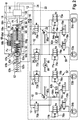
- Fig. 2 shows a schematic representation of an embodiment of the recuperative braking system.
- FIG. 2 schematically reproduced braking system is advantageously used for example in a hybrid and in an electric vehicle.
- the applicability of the braking system described below is not limited to use in a hybrid or in an electric vehicle.
- the brake system has a first brake circuit 50 with a first wheel brake cylinder 53a and a second wheel brake cylinder 54a.
- the brake system also has a second brake circuit 52 having a third wheel brake cylinder 53b and a fourth wheel brake cylinder 54b.
- the brake system is designed with two brake circuits 50 and 52 for a vehicle with X-brake circuit split.
- the first wheel brake cylinder 53a and the third wheel brake cylinder 53b are associated with a first vehicle axle
- the second wheel brake cylinder 54a and the fourth wheel brake cylinder 54b are associated with another vehicle axle.
- first wheel brake cylinder 53a and the third wheel brake cylinder 53b may be associated with the front axle, while the second wheel brake cylinder 54a and the fourth wheel brake cylinder 54b are associated with the rear axle.
- the wheels associated with a brake circuit 50 and 52 may in particular be arranged diagonally on the vehicle.
- the braking system described below is not limited to an X-brake circuit distribution. Instead, the brake system can also be used if the wheels assigned to a common brake circuit 50 or 52 are arranged on one side or on one side of the vehicle.
- the brake system has a master cylinder 62, which can be executed, for example, as a tandem master cylinder.
- the master cylinder 62 may have at least one adjustable piston 61a and 61b which is at least partially adjustable in at least one pressure chamber 62a or 62b of the master cylinder 62.
- the master brake cylinder 62 preferably comprises a first adjustable piston 61a, which can be labeled as a rod piston and which at least partially engages in a first pressure chamber 62a of the master brake cylinder 62 assigned to the first brake circuit 50 protrudes, and as a floating piston markable second adjustable piston 61b, which projects at least partially into a second brake chamber 52 associated second pressure chamber 62b of the master cylinder 62.
- the floating piston is adjustable so that upon an adjustment of the floating piston in a first direction, the first inner volume of the first pressure chamber 62a decreases, while the inner volume of the second pressure chamber 62b increases. Accordingly, by adjusting the floating piston in a second direction, the inner volume of the first pressure chamber 62a may increase as the inner volume of the second pressure chamber 62b decreases.
- the brake system is not limited to the use of a tandem master cylinder or a particular design of the master cylinder 62.
- the master cylinder 62 may be connected via at least one brake fluid exchange opening, such as a sniffer bore, with a (not shown) brake fluid reservoir.
- the brake system preferably includes a brake actuator 64, such as a brake pedal, disposed on the master cylinder 62.
- the brake actuator 64 is disposed on the master cylinder 62 such that upon actuation of the brake actuator 64 having at least one threshold amount, a driver brake force Ff applied to the brake actuator 64 is applied to the at least one adjustable piston 61a and 61b, such as the rod piston and the floating piston. is transferable, that the piston 61a and 61b is adjustable by means of the driver brake force Ff.
- an internal pressure in at least one pressure chamber 62 a and 62 b of the master cylinder 62 is increased by means of this adjustment of the piston.
- the adjustment movement of the at least one piston 61a and 61b can counteract a master brake cylinder counterforce Fg which results from an internal pressure and / or at least one spring 63a and 63b in the at least one pressure chamber 62a and 62b. Also, a restoring force Fr of a restoring spring 65 may be directed against the adjusting movement of the at least one piston 61a and 61b.
- the brake system preferably also comprises at least one brake actuation element sensor 66, by means of which the actuation amount of the actuation of the brake actuation element 64 by the driver can be determined.
- the brake actuator sensor 66 may include, for example, a pedal travel sensor, a differential travel sensor, and / or a rod travel sensor. To capture the Actuating strength, which corresponds to the driver's brake request, however, is also a different type of sensor used instead of or in addition to the listed here sensor types.
- the illustrated brake system also includes a brake booster 68, preferably an electro-mechanical brake booster 68.
- the brake booster 68 may in particular be a continuously controllable / continuously controllable brake booster.
- An electromechanical brake booster 68 is characterized by a variable gain.
- the electromechanical brake booster 68 can be changed in its characteristics (by means of the control device 100 described in more detail below).
- the brake system may also have a brake booster 68 of a different type. It is sufficient that by means of the brake booster 68 a variable by means of the control device 100 amplifier power Fv together with the driver brake force Ff to the at least one piston 61a and 61b is transferable.
- Fig. 2 As in Fig. 2 is shown act on an output rod 68a of an (electro-mechanical) brake booster 68, and corresponding to the brake actuator 64, thus several forces. While the driver brake force Ff and booster amplifier force Fv push the output rod 68a toward the master cylinder 62, the return force Fr of the return spring 65 and the master cylinder counterforce Fg counteract the braking movement of the output rod 68a.
- FIG. 2 4 shows the configuration of the mechanism of the brake booster 68 with a motor 68e that is in engagement with a booster body 68c (with a threaded surface 68d) via a gear 68b, the booster body 68c, together with an input rod 68f transmitting the driver braking force Ff, acting on a reaction disk 68g the output rod 68a contacted, is to be interpreted only as an example.
- the equipment of the motor 68e with a sensor 68h, such as a rotation angle sensor, is optional.
- the input rod 68f may be supported on the booster body 68c via another spring 68i.
- Each of the brake circuits 50 and 52 is formed with a high-pressure switching valve 70a and 70b and a switching valve 72a and 72b so that the driver can brake directly into the wheel brake cylinders 53a, 53b, 54a and 54b via the master cylinder 62.
- the first wheel brake cylinder 53a is assigned a first wheel inlet valve 74a and the second wheel brake cylinder 54a has a second wheel inlet valve 75a, each with a bypass line 76a extending parallel thereto and a check valve 77a arranged in each bypass line 76a.
- a first Radauslassventil 78a the first wheel brake cylinder 53a and a second Radauslassventil 79a associated with the second wheel brake cylinder 54a.
- a third wheel inlet valve 74b may be associated with the third wheel brake cylinder 53b and a fourth wheel inlet valve 75b with the third wheel brake cylinder 54b.
- Parallel to each of the two Radeinlassventile 74b and 75b of the second brake circuit 52 may each have a bypass line 76b arranged therein with a check valve 77b. Furthermore, in the second brake circuit 52, a third Radauslassventil 78b the third wheel brake cylinder 53b and a fourth wheel outlet valve 79b may be associated with the fourth wheel brake cylinder 54b.
- each of the brake circuits 50 and 52 includes a pump 80a and 80b whose suction side is connected to the wheel outlet valves 78a and 79a or 78b and 79b and whose discharge side is directed to the associated switching valve 72a or 72b.
- a storage chamber 82a or 82b eg, a low pressure accumulator and / or a storage chamber
- a relief valve 84a or 80b located between the pump 80a or 80b and the storage chamber 82a or 82b 84b also have the brake circuits 50 and 52.
- the pumps 80a and 80b may be disposed on a common shaft 86 of an engine 88.
- Each of the pumps 80a and 80b may be formed as one-piston pumps. However, instead of a single-piston pump, another type of pump may be used for at least one of the pumps 80a and 80b.
- Differently executed modulation systems such. As pumps with several or fewer pistons, asymmetric pumps or gear pumps are also used.
- each of the two brake circuits 50 and 52 may comprise at least one pressure sensor 90, in particular on a supply line of a first wheel brake cylinder 53a and / or third wheel brake cylinder s53b used as a front axle brake caliper.
- the cooperating with a (not shown) generator braking system and is also equipped with the above-described control device 100.
- the hydraulic braking torque the braking system can be reduced at an increasing generator braking torque.
- the hydraulic braking torque be increased so that despite a time decrease of the generator braking torque of the driver's braking request / the target total braking torque can be reliably maintained.
- Regenerative braking is characterized by the fact that the vehicle has a not constant, but known generator braking torque of the generator acts. About the known braking request of the driver and the generator braking torque, a coordinator to calculate the required to comply with the target total braking torque hydraulic braking torque. If the currently available generator braking torque is sufficient to fully implement the driver's braking request, braking can be stopped purely regeneratively by means of the brake system shown here.
- a hydraulic braking torque can be built up by means of the braking torque shown here in addition to the generator braking torque, wherein the sum of the generator braking torque to the hydraulic braking torque preferably equal to the driver's braking request / target total -Bremsmoment is. If no generator braking torque is activated, for example because of a complete charging of the at least one vehicle battery and / or a current vehicle speed below a minimum generator insertion speed, a purely hydraulic braking can also be carried out by means of the braking system shown here.
- the operation of the brake system is thus adaptable to a current applicability of the generator that at the same time with a quick charging of the vehicle battery to reduce energy consumption and pollutant emission of the vehicle equipped with the braking system of the driver's braking request / the target total braking torque is reliably maintained.
- a master brake cylinder pressure and the master brake cylinder counterforce Fg are below their corresponding to the driver brake force Ff (at a generator braking torque equal to zero) comparison values.
- the reduction of the master brake cylinder counterforce Fg (due to the brake fluid displacement via the at least one valve control signal 12 actuated valve 78a, 78b, 79a, 79b, 70a and / or 70b) conventionally affects the balance of forces from the forces Ff, Fv, Fr and In a prior art brake system, during operation of the brake actuator 64, the driver senses this change in master cylinder counterforce as jitter, recoil, vibration, and / or retraction of the brake actuator 64.
- the booster force Fv can be adapted to the change of the master brake cylinder counterforce Fg.
- the driver senses a reaction of the brake fluid volume displaced via the at least one valve 78a, 78b, 79a, 79b, 70a and / or 70b actuated by means of the valve control signal 12.
- This can also be described as reacting to a changing master brake cylinder counterforce Fg with an adapted boosting force Fv in order to obtain the force equilibrium from the forces Ff, Fv, Fr and Fg. Reactions to the brake actuator 64 are reliably prevented in this way. (This function is described above by the term "power veneering.")
- the force blending functionality of the brake system described herein is not limited to the jump-in range (eg, a vacuum booster).
- the usable for recuperative braking range of delay is thus significantly extended.
- a power supply U of the brake booster 68 can be controlled.
- the control device can also output the closing signal 24 already described above during the operation of the at least one pump 80a and 80b.
- the control device 100 may additionally be designed to take into account, during the activation of the brake booster 68, a sensor signal / information signal 18 of at least one sensor 66 and / or 68h. An advantageous control quality is thus ensured.
- the brake system described here despite its variety of executable functions with an (electro-mechanical) brake booster 68 and a (modified) standard ESP modulation system. On a soiruator can be omitted. Due to the small number of components of the brake system, which in the blending of the generator braking torque and a subsequent Adjusting the amplifier force Fv involved, the braking system has a significantly reduced complexity. This reduces the cost of the braking system. In addition, the braking system can be easily mounted in a vehicle because of its relatively simple structure. It also requires relatively little space.
- Active pressure assemblies, d. H. Brake requests without operation of the brake actuator 64 may occur in the illustrated brake system via the at least one pump 80a and 80b and the opened high pressure switching valves 70a and 70b and the closed wheel exhaust valves 78a, 78b, 79a and 79b.
- active pressure structures can also be done by means of the (electro-mechanical) brake booster 68. (The desired pressure build-up dynamics, noise and brake feel can determine which actuator is used to build up the pressure.)
- the braking system In the event of a failure of the modulation system, the braking system still has an increased braking function on all wheel brake cylinders 53a, 53b, 54a and 54b and thus has no additional functional restrictions compared to a conventional system.
- the driver In the event of failure of the (electro-mechanical) brake booster 68, the driver may be assisted in actuating the brake operating member by means of the modulation system (by means of the at least one pump 80a and 80b). Even in this case of error, the function restriction does not differ from a conventional brake system with a brake booster 68, such as a vacuum brake booster.
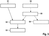
- Fig. 3 shows a flowchart for illustrating a first embodiment of the method for operating a recuperative braking system.
- a recuperative braking system in particular a hybrid or electric vehicle, can be operated.
- the above described embodiments of the control device and the recuperative braking system may be operated by the method described herein. It should be noted, however, that the feasibility of the method described below is not limited to the use of these embodiments or to a specific design of the brake system operated therewith.
- step S1 at least one valve of a brake circuit of the brake system is actuated before and / or during operation of a generator of the brake system in such a way that brake fluid flows into at least one at least partially open at least one valve from a master brake cylinder of the brake system and / or the at least one brake circuit Storage volume of the respective brake circuit is moved.
- a brake pressure build-up in the at least one brake circuit and / or at least one wheel brake cylinder (such as a wheel brake caliper) connected thereto can be prevented despite actuation of a brake actuation element arranged on the master brake cylinder.
- the master cylinder brake actuator such as a brake pedal
- a hydraulic braking torque is exerted on at least one of the wheels.
- the attributable braking action of the at least one wheel brake cylinder can thus be used for an advantageously high recuperation efficiency without exceeding a predetermined total vehicle deceleration predetermined by the driver.
- At least one wheel outlet valve or at least one high-pressure switching valve can be at least partially opened as the at least one valve.
- the brake fluid can be displaced via the at least partially opened at least one wheel outlet valve or the at least partially opened at least one high-pressure switching valve into a storage chamber as the at least one storage volume.
- the at least one storage chamber is preferably a low-pressure storage chamber. If the brake fluid is displaced over the at least partially opened at least one high-pressure switching valve, this is additionally carried out via at least one check valve-free line device between the respective high-pressure switching valve and the associated storage volume.
- the displacement of the brake fluid via the at least one high-pressure switching valve is additionally associated with the advantage that even a comparatively low brake pressure build-up in the at least one wheel brake cylinder does not occur.
- a brake pressure of (almost) zero can be set / maintained in the at least one wheel brake cylinder.
- the method also includes a method step S2 in which a desired force difference quantity with respect to an amplifier force exerted by a brake booster taking into account a generator brake torque information with respect to a force exerted by the generator generator braking torque, a measured or estimated master cylinder pressure value and / or one of at least the generator brake torque information or the master brake cylinder pressure variable derived evaluation value is set. Subsequently, the brake booster is controlled in the method step S3, taking into account the set desired force difference quantity. In this way, the amplifier power can be varied by an actual force difference corresponding to the desired force difference variable.
- the boosting force can thus be reduced so that a reduction of the master brake cylinder counterforce caused by the displacement of the brake fluid into the at least one storage volume compensates (at least in part) for a time increase / increase of the generator braking torque becomes.
- the target force difference quantity is at least taking into account the generator braking torque (or by the change of the generator braking torque increased or reduced hydraulic braking torque) and a braking torque / drag characteristic of the brake system with respect to a relation between a hydraulic braking torque of the brake system and a characterized caused master cylinder counterforce on a arranged on a master cylinder of the brake system brake actuator.
- the desired force differential quantity may be set to the brake operating member taking into account the measured master cylinder pressure magnitude and a master cylinder pressure / drag characteristic of the brake system with respect to a relation between a master cylinder pressure and the master brake cylinder counterforce caused thereby.
- the method preferably also has a method step S4 in which a generator braking torque of the generator that is reduced on the basis of a reduction specification to the operated generator or a deactivation of the generator is masked.
- the blending takes place in the method step S4 by pumping brake fluid by means of at least one pump of the respective brake circuit from the at least one storage volume into at least one wheel brake cylinder of the brake system.
- the hydraulic braking torque can thus be increased so that despite the reduced generator braking torque of the driver's braking request / the target total braking torque is reliably maintained.
- a desired pump power quantity of the at least one pump of the brake system can be determined taking into account the reduced generator braking torque. Subsequently, the at least one pump can be controlled taking into account the set desired pump power quantity. As an alternative, the at least one pump can also be operated until a predetermined brake pressure and / or a desired hydraulic braking torque are reached.
- method steps S2 and S3 can again be carried out.
- the amplifier force can be increased by an actual force difference corresponding to the desired force difference variable, so that despite the increased due to the return pump master cylinder pressure and therefore increased master cylinder counterforce the desired balance of forces.
- a method step S5 can also be carried out, in which at least one changeover valve of the brake system is controlled into a closed state during operation of the at least one pump.
- a recoil / a reaction of the return and the pump pulsations carried out to the Brake actuator can be prevented.
- the driver can still increase the driver's braking request / setpoint braking torque. This is ensured because volume can flow in this case via the check valve of the changeover valve in the associated brake circuit.
- the continuously adjustable changeover valve can be slowly opened to compensate for any pressure differences (step S6).
- the balancing of the pressure differences can take place with additional consideration of the continuously measured master brake cylinder pressure.
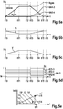
- Fig. 4a to 4e show five coordinate systems for illustrating a second embodiment of the method for operating a recuperative braking system.
- the method will be described using the recuperative braking system set forth above, the first wheel brake cylinder and the third wheel brake cylinder being associated with a first axle formed as a front axle and the second wheel brake cylinder and the fourth wheel brake cylinder being associated with a second axle formed as a rear axle.
- the feasibility of the method is not limited to the use of the braking system described above or to this assignment of the wheel brake cylinder.
- the abscissa is the time axis t.
- the ordinate of the coordinate system of Fig. 4a returns a braking torque b, while the ordinate of Fig. 4b indicates a numerical value, the ordinate of Fig. 4c corresponds to a displaced brake fluid volume V and the ordinate of the coordinate system of Fig. 4d indicates a current I.
- the abscissa of the coordinate system of Fig. 4e is a first axle braking torque ba1 exerted on the first axle, while the ordinate of the co - ordinate system is Fig. 4e represents an exerted on the second axis axle brake ba2.
- the brake operating element of the braking system operated by means of the method is in its starting position / non-actuating position.
- the driver does not exert any force on the brake actuating element until time t0.
- the driver exerts an increasing force on the brake operating member, whereby this is adjusted.
- the complete driver brake request can be carried out purely regeneratively. This is possible because the requested by the driver target total braking torque bges between times t0 and t1 is below the maximum executable can-generator braking torque bkann.
- the generator braking torque bgen can be set in accordance with the target total braking torque bges.
- step S1 For purely regenerative braking between times t0 and t1, the wheel outlet valves are opened, whereby the brake fluid volume displaced by the driver from the master brake cylinder is (almost) completely discharged into the storage chambers (e.g., low pressure storage chambers) (step S1).
- the volume V in the at least one storage chamber increases accordingly between times t0 and t1.
- no hydraulic brake pressure is built up and a first partial hydraulic braking torque bh1-3 of the first wheel brake cylinder and the third wheel brake cylinder and a second partial hydraulic braking torque bh2-4 of the second wheel brake cylinder and the fourth wheel brake cylinder remain zero between the times t0 and t1.
- the four wheel inlet valves and the four wheel exhaust valves are each controlled to an open state between times t0 and t1.
- this is done by an output to the first Radeinlassventil and the third Radeinlassventil first valve control signal IE1-3 with a current zero, one to the second Radeinlassventil and the fourth wheel inlet valve outputs a second valve control signal IE2-4 having a zero current, a third valve control signal IA1-3 sent to the first wheel outlet valve and the third wheel outlet valve with a non-zero current (eg equal to one), and one to the second wheel outlet valve and the fourth wheel exhaust valve provided fourth valve control signal IA2-4 with a non-zero current (eg, equal to one).
- Between times t0 and t1 the pump control signal Ip and the closing signal Is are kept equal to zero.
- the height of the missing pressure build-up and thus the missing Master brake cylinder counterforce at the (electromagnetic) brake booster determined.
- a desired balance between the boosting force Fv and the master cylinder counterforce Fg can be maintained, the boosting force Fv being a product of the boost factor fv and a (not shown) Driver braking force correlated (steps S2 and S3).
- the desired total braking torque bges requested by the driver is greater than the maximum executable can-generator braking torque bkann.
- a first hydraulic partial braking torque bh1-3 not equal to zero can be established in the first wheel brake cylinder and in the third wheel brake cylinder.
- the first and third Radauslassventils is closed by a third valve control signal IA1-3 equal to zero.
- a ⁇ p control (delta-p control) of the (preferably continuously adjustable) second and fourth Radeinlassventile (second valve control signal IE2-4 between zero and one) is a pressure control in each brake circuit executable that a sum of the first hydraulic Opera sectionbremsmoments bh1-3 and the generator braking torque bgen the target total braking torque bges corresponds.
- the hydraulic brake pressure in the front-wheel brake cylinders also results in an increase in the master cylinder counterforce (non-zero).
- the amplifier factor fv can thus be kept constant during times t1 to t4.
- the driver's braking request / the target total braking torque bges reaches a local maximum. From time t3 the driver reduces the Driver braking request / the nominal total braking torque bges. Between times t3 and t4, the first partial hydraulic braking torque bh1-3 is first reduced. For this purpose, only volume is taken from the first wheel brake cylinder and the third wheel brake cylinder by the first Radauslassventil and the third Radauslassventil be opened. The opening of the first and third Radauslassventils carried by a third valve control signal IA1-3 not equal to zero (eg equal to one).
- the reduction of the target total braking torque bges can be performed via a reduction of the generator braking torque bgen. This takes place until the driver's braking request / the desired total braking torque bges reaches a local minimum at time t5.
- Fig. 5a to 5e show five coordinate systems for illustrating a third embodiment of the method for operating a recuperative braking system. (The abscissae and ordinates of the coordinate systems of Fig. 5a to 5e correspond to the Fig. 4a to 4e .)
- the brake operating element of the braking system operated by means of the method is in its starting position / non-actuating position.
- the driver requests a desired total braking torque bges, which is less than or equal to a maximum executable can-generator braking torque bkann.
- the target total braking torque bges to be executed between times t10 and t13 reaches a maximum at time t11 and remains constant between times t11 and t13).
- the braking request of the driver is thus available for charging a vehicle battery.
- step S1 opening all four Radeinlassventile (by a first valve control signal IE1-3 equal to zero and a second valve control signal IE2-4 equal to zero) and opening all four Radauslassventile (by means of a third valve control signal IA1-3 not equal to zero and a fourth valve control signal IA2-4 not equal to zero) the first hydraulic partial braking torque bh1-3 of the first and third Wheel brake and the second partial hydraulic braking torque bh2-4 of the second and fourth wheel brake cylinder between the times t10 and t13 held despite the operation of the brake actuator element is equal to zero (step S1).
- the generator braking torque bgen is also set equal to the desired total braking torque bges, and the amplifier power / amplifier factor fv is adapted to the volume V shifted into the at least one storage volume (method steps S2 and S3). This ensures the advantages already described above.
- the maximum executable can-generator braking torque bkann decreases, for example due to a charging state of the vehicle battery and / or a reduction of the current speed of the vehicle below a generator insertion minimum speed.
- the maximum executable can-generator braking torque bkann is smaller than the driver's braking request / the target total braking torque bges.
- the driver's braking request can nevertheless be reliably maintained.
- all four Radauslassventile by means of a third valve control signal IA1-3 equal to zero and a fourth valve control signal IA2-4 equal to zero from the time t13 closed.
- the at least one pump of the brake system can be activated from time t13 so that brake fluid is pumped from the storage volume into the wheel brake cylinders (method step S4). Therefore, the volume V existing in the storage volume decreases from time t13. In this way, both at the front and at the rear axle, a hydraulic braking torque can be built so that the target total braking torque bges is reliably maintained.
- the at least one reversing valve is closed by means of a closing signal Is for the time of the return conveyance (method step S5). If the at least one changeover valve is designed as a normally open valve, this is done by a closing signal Is not equal to zero.
- the driver can increase the target total braking torque from the time t14 still. Volume flows in this case via the check valve of the changeover valve in the brake circuit. It will be on it pointed out that by means of the operation of the pump even after the time t14, the increased target total braking torque bges is still executable by an increase of the hydraulic partial braking torques bh1-3 and bh2-4, although the maximum executable can-generator braking torque bkann continuously decreases and becomes 0 at time t15.
- the amplifier power / the amplifier factor fv is adapted to the return of the volume V shifted into the at least one storage volume (method steps S2 and S3).
- the (advantageously designed as a continuously adjustable valve) at least one switching valve can be opened slowly to compensate for any pressure differences (step S6). After the completed return conveyance of the volume V from the at least one storage volume back into the at least one brake circuit is braked exclusively hydraulically.
- the amplification factor fv of the brake booster has returned to the conventional output value.
- Fig. 6a to 6e show five coordinate systems for illustrating a fourth embodiment of the method for operating a recuperative braking system. (The abscissae and ordinates of the coordinate systems of Fig. 6a to 6e correspond to the Fig. 4a to 4e .)
- the brake operating element of the braking system operated by means of the method is in its starting position / non-actuating position. From the time t20, the driver exerts an increasing force on the brake operating member. Between the times t20 and t21 can be braked in the manner already described above purely regenerative (step S1). From time t21 onwards, due to a desired total braking torque bges requested by the driver, a first partial hydraulic braking torque bh1-3 not equal to zero in the first and third wheel brake cylinders can be greater than the maximum executable optional generator braking torque b by closing the first and third wheel outlet valves built up.
- the additional volume displacement by the driver by means of the actuation of the brake actuator can be used to a desired hydraulic braking torque build-up on the front axle.
- no Brake pressure build-up takes place in the wheel brake cylinders of the rear axle can be ensured.
- a suitable control ⁇ p control, delta-p control
- the amplifier factor fv is adjusted so that despite the volume V displaced into the at least one storage volume, the desired equilibrium of forces exists (method steps S2 and S3).
- the maximum executable can-generator braking torque b may increase to the time t25. This can be used for an increase in the generator braking torque bgen for faster charging of the vehicle battery.
- brake fluid can flow into the at least one storage volume so that the volume V present therein is from time t25 increases.
- the second hydraulic partial braking torque bh2-4 of the second and fourth wheel brake cylinders can be kept (almost) equal to zero.
- the partial hydraulic braking torque bh1-3 of the first and third wheel brake cylinders between times t25 and t26 can be reduced so that the generator braking torque bgen can be increased according to the increase of the maximum executable can-generator braking torque bkann while the driver's braking request is reliably maintained ,
- the booster force / amplifier factor fv of the brake booster is also adjusted in this operating situation as a function of the current brake actuation travel / the current driver brake force and the actual master brake cylinder pressure present. If, during this phase, a pump should be advantageous in order to shift an additional volume into the first and third wheel brake cylinders, the at least one changeover valve can be closed and then slowly opened for the duration of the pump activation. (This is in Fig. 6d However, not shown.) After a complete displacement of brake fluid from the first and third wheel brake cylinder via the second and fourth Radeinlassventil in the at least one storage volume can be braked purely regenerative.
Landscapes
- Engineering & Computer Science (AREA)
- Transportation (AREA)
- Mechanical Engineering (AREA)
- Physics & Mathematics (AREA)
- Fluid Mechanics (AREA)
- Chemical & Material Sciences (AREA)
- Combustion & Propulsion (AREA)
- Electromagnetism (AREA)
- Power Engineering (AREA)
- Regulating Braking Force (AREA)
- Braking Systems And Boosters (AREA)
Applications Claiming Priority (2)
| Application Number | Priority Date | Filing Date | Title |
|---|---|---|---|
| DE102012211278.2A DE102012211278A1 (de) | 2012-06-29 | 2012-06-29 | Verfahren zum Betreiben eines rekuperativen Bremssystems eines Fahrzeugs, Steuervorrichtung für ein rekuperatives Bremssystem eines Fahrzeugs und rekuperatives Bremssystem |
| PCT/EP2013/059222 WO2014000928A1 (de) | 2012-06-29 | 2013-05-03 | Verfahren zum betreiben eines rekuperativen bremssystems eines fahrzeugs, steuervorrichtung für ein rekuperatives bremssystem eines fahrzeugs und rekuperatives bremssystem |
Publications (2)
| Publication Number | Publication Date |
|---|---|
| EP2867076A1 EP2867076A1 (de) | 2015-05-06 |
| EP2867076B1 true EP2867076B1 (de) | 2018-11-07 |
Family
ID=48236969
Family Applications (1)
| Application Number | Title | Priority Date | Filing Date |
|---|---|---|---|
| EP13719872.7A Active EP2867076B1 (de) | 2012-06-29 | 2013-05-03 | Verfahren zum betreiben eines rekuperativen bremssystems eines fahrzeugs und rekuperatives bremssystem |
Country Status (9)
| Country | Link |
|---|---|
| US (1) | US9827965B2 (zh) |
| EP (1) | EP2867076B1 (zh) |
| JP (1) | JP6220872B2 (zh) |
| KR (3) | KR20190114032A (zh) |
| CN (2) | CN104379418B (zh) |
| BR (1) | BR112014032183B1 (zh) |
| DE (1) | DE102012211278A1 (zh) |
| MX (1) | MX366475B (zh) |
| WO (1) | WO2014000928A1 (zh) |
Families Citing this family (28)
| Publication number | Priority date | Publication date | Assignee | Title |
|---|---|---|---|---|
| DE102012211278A1 (de) * | 2012-06-29 | 2014-01-02 | Robert Bosch Gmbh | Verfahren zum Betreiben eines rekuperativen Bremssystems eines Fahrzeugs, Steuervorrichtung für ein rekuperatives Bremssystem eines Fahrzeugs und rekuperatives Bremssystem |
| DE102012222978A1 (de) * | 2012-12-12 | 2014-06-12 | Robert Bosch Gmbh | Verfahren zum Betreiben eines Bremssystems eines Fahrzeugs und Steuervorrichtung für ein Bremssystem eines Fahrzeugs |
| US9493075B2 (en) * | 2014-03-25 | 2016-11-15 | Ford Global Technologies, Llc | Regenerative braking control system and method |
| DE102014210559A1 (de) | 2014-06-04 | 2015-12-17 | Robert Bosch Gmbh | Steuervorrichtung für ein rekuperatives Bremssystem und Verfahren zum Betreiben eines rekuperativen Bremssystems |
| DE102014210550A1 (de) * | 2014-06-04 | 2015-12-17 | Robert Bosch Gmbh | Sensorvorrichtung für ein mit einem elektromechanischen Bremskraftverstärker ausgestattetes Bremssystem und Verfahren zum Ermitteln einer Bremswunschvorgabe an ein mit einem elektromechanischen Bremskraftverstärker ausgestattetes Bremssystem |
| FR3029479A1 (fr) * | 2014-12-08 | 2016-06-10 | Peugeot Citroen Automobiles Sa | Dispositif d’assistance electrique du freinage comportant un reducteur du type cycloidal |
| DE102015200106B3 (de) * | 2015-01-08 | 2016-05-12 | Ford Global Technologies, Llc | Steuerungsverfahren für ein hydraulisches Bremssystem eines Kraftfahrzeugs sowie hydraulisches Bremssystem |
| DE102015212188A1 (de) | 2015-06-30 | 2017-01-05 | Robert Bosch Gmbh | Verfahren zum Betreiben eines fahrzeugeigenen Bremssystems mit einem Elektromotor und Steuervorrichtung für zumindest einen Elektromotor eines fahrzeugeigenen Bremssystems |
| US10569657B2 (en) * | 2016-02-16 | 2020-02-25 | Toyota Jidosha Kabushiki Kaisha | Vehicle brake system |
| JP6544261B2 (ja) | 2016-02-16 | 2019-07-17 | トヨタ自動車株式会社 | ブレーキシステム |
| DE102016208529A1 (de) * | 2016-05-18 | 2017-11-23 | Robert Bosch Gmbh | Bremssystem für ein Fahrzeug und Verfahren zum Betreiben eines Bremssystems eines Fahrzeugs |
| CN108706010A (zh) * | 2017-05-09 | 2018-10-26 | 朱海燕 | 作业方便的车辆选挡自动行车系统 |
| DE102017213392A1 (de) * | 2017-08-02 | 2019-02-07 | Robert Bosch Gmbh | Steuervorrichtung und Verfahren zum Betreiben eines Simulator-bestückten hydraulischen Bremssystems eines Fahrzeugs |
| DE102017214602A1 (de) * | 2017-08-22 | 2019-02-28 | Robert Bosch Gmbh | Steuervorrichtung und Verfahren zum Betreiben einer Fahrzeugverzögerungsvorrichtung eines Fahrzeugs |
| US10696281B2 (en) | 2017-09-25 | 2020-06-30 | Mando Corporation | Electric brake system and operating method thereof |
| CN109552290B (zh) | 2017-09-25 | 2022-12-23 | 株式会社万都 | 电子制动系统以及工作方法 |
| DE102018206566A1 (de) | 2018-04-27 | 2019-10-31 | Robert Bosch Gmbh | Fahrzeugbremssystem und Verfahren zur Bremsdrucksteigerung in einem ersten Radbremszylinder und Bremsdruckbegrenzung in einem zweiten Radbremszylinder eines Fahrzeugbremssystems |
| DE102018009370A1 (de) * | 2018-11-29 | 2020-06-04 | Zf Active Safety Gmbh | Elektrohydraulische Fahrzeug-Bremsanlage mit redundanter Hydraulikdruckerzeugung und Verfahren zum Betreiben der Bremsanlage |
| KR102623777B1 (ko) * | 2019-05-07 | 2024-01-11 | 에이치엘만도 주식회사 | 브레이크 장치 및 그 제어 방법 |
| DE102019113758A1 (de) * | 2019-05-23 | 2020-11-26 | Zf Active Safety Gmbh | Verfahren zur Steuerung eines hydraulischen Bremssystems bei einem regenerativen Bremsvorgang, hydraulisches Bremssystem, Computerprogrammprodukt, Steuereinheit und Kraftfahrzeug |
| DE102019128744A1 (de) * | 2019-10-24 | 2021-04-29 | Zf Active Safety Gmbh | Verfahren zum Erkennen von unerwünschten Schwingungen eines Aktuators einer elektromechanischen Bremse, elektronisch gesteuertes Bremssystem, Computerprogrammprodukt, Steuergerät und Kraftfahrzeug |
| CN111605526A (zh) * | 2020-06-03 | 2020-09-01 | 安徽江淮汽车集团股份有限公司 | 制动压力调节方法、装置、设备及可读存储介质 |
| CN111806241B (zh) * | 2020-06-28 | 2022-02-18 | 同济大学 | 一种轨道交通列车再生电能回收空间确定方法 |
| DE102021206811A1 (de) * | 2021-06-30 | 2023-01-05 | Robert Bosch Gesellschaft mit beschränkter Haftung | Verfahren zur Steuerung eines hydraulischen Volumens |
| CN113525319B (zh) * | 2021-09-03 | 2022-05-31 | 吉林大学 | 一种基于可调储液缸的真空助力再生制动控制方法 |
| WO2023213955A2 (de) | 2022-05-05 | 2023-11-09 | Thomas Leiber | Fahrdynamiksystem, fahrzeug sowie verfahren zum betreiben eines fahrdynamiksystems |
| DE102022205403A1 (de) * | 2022-05-30 | 2023-11-30 | Robert Bosch Gesellschaft mit beschränkter Haftung | Verfahren zum Aktuieren einer Mechanik in einer Bremskraftverstärkereinrichtung eines Bremssystems und Bremssystem |
| DE102022116353A1 (de) | 2022-06-30 | 2024-01-04 | Ipgate Ag | Fahrdynamiksystem für ein Fahrzeug mit Rädern, Schaltventil, inbesondere für ein entsprechendes Fahrdynamiksystem, Verfahren zum Einstellen eines Bremsdrucks, Primärsteuereinheit sowie Fahrzeug mit entsprechender Primärsteuereinheit |
Family Cites Families (53)
| Publication number | Priority date | Publication date | Assignee | Title |
|---|---|---|---|---|
| DE19604134B4 (de) | 1996-02-06 | 2004-11-11 | Robert Bosch Gmbh | Verfahren und Vorrichtung zur Steuerung der Bremsanlage von Kraftfahrzeugen mit elektrischem Antrieb |
| US6467267B2 (en) * | 1999-07-14 | 2002-10-22 | Bosch Braking Systems Co., Ltd. | Fluid pressure boosting device and brake system employing the same |
| US6957870B2 (en) * | 1999-12-24 | 2005-10-25 | Toyota Jidosha Kabushiki Kaisha | Braking pressure control apparatus capable of switching between two brake operating states using power-operated and manually operated pressure sources, respectively |
| DE10139335A1 (de) * | 2000-08-11 | 2002-03-07 | Aisin Seiki | Hydraulische Bremsvorrichtung für ein Fahrzeug |
| JP2002255018A (ja) * | 2001-02-28 | 2002-09-11 | Bosch Braking Systems Co Ltd | ブレーキシステム |
| JP4147850B2 (ja) * | 2002-02-15 | 2008-09-10 | 日産自動車株式会社 | 制動制御装置 |
| US20050269875A1 (en) * | 2004-06-08 | 2005-12-08 | Kazuya Maki | Vehicle brake device |
| US7146266B2 (en) * | 2004-07-01 | 2006-12-05 | Ford Global Technologies, Llc | Controlling a hydraulic hybrid vehicle powertrain having an internal combustion engine and a hydraulic pump/motor |
| DE102005000655A1 (de) | 2005-01-04 | 2006-07-13 | Robert Bosch Gmbh | Bilderfassungseinrichtung |
| DE102005030223A1 (de) * | 2005-06-29 | 2007-01-04 | Lucas Automotive Gmbh | Bremskrafterzeuger für eine hydraulische Fahrzeugbremsanlage |
| KR101006987B1 (ko) * | 2005-12-07 | 2011-01-12 | 주식회사 만도 | 전기모터가 장착된 차량의 회생제동방법 |
| JP4775078B2 (ja) * | 2006-04-03 | 2011-09-21 | 株式会社アドヴィックス | 車両用ブレーキ制御装置 |
| JP2007308097A (ja) * | 2006-05-22 | 2007-11-29 | Toyota Motor Corp | 車両およびその制御方法 |
| JP4375385B2 (ja) * | 2006-11-07 | 2009-12-02 | トヨタ自動車株式会社 | ブレーキ制御装置 |
| DE102006061022A1 (de) * | 2006-12-22 | 2008-06-26 | Lucas Automotive Gmbh | Bremskrafterzeuger für eine hydraulische Fahrzeugbremsanlage und mit diesem ausgestattete Fahrzeugbremsanlage |
| EP1950076B1 (en) * | 2007-01-25 | 2010-07-21 | Honda Motor Co., Ltd | Vehicle drive device and hydraulic circuit thereof |
| US8000861B2 (en) * | 2007-04-13 | 2011-08-16 | Advics Co., Ltd. | Braking control apparatus for vehicle |
| JP5014919B2 (ja) * | 2007-08-17 | 2012-08-29 | 日立オートモティブシステムズ株式会社 | ブレーキ制御装置 |
| DE102008003664B4 (de) * | 2008-01-09 | 2023-03-23 | Robert Bosch Gmbh | Bremssystem und Verfahren zum Betreiben eines Bremssystems |
| JP5066004B2 (ja) * | 2008-06-06 | 2012-11-07 | 日立オートモティブシステムズ株式会社 | ブレーキシステム |
| FR2933936B1 (fr) * | 2008-07-17 | 2014-10-10 | Bosch Gmbh Robert | Servomoteur reglable d'assistance au freinage |
| JP5150410B2 (ja) * | 2008-08-25 | 2013-02-20 | 日立オートモティブシステムズ株式会社 | ブレーキ装置 |
| DE102009026960A1 (de) * | 2008-12-18 | 2010-07-01 | Robert Bosch Gmbh | Verfahren zur Steuerung einer Bremsbetätigung eines Hybridfahrzeugs |
| DE102009005937A1 (de) | 2009-01-23 | 2010-07-29 | Continental Teves Ag & Co. Ohg | Elektrohydraulisches Bremssystem sowie Verfahren zu dessen Betrieb |
| JP2010215069A (ja) * | 2009-03-16 | 2010-09-30 | Honda Motor Co Ltd | Bbw式ブレーキ装置 |
| US8894159B2 (en) * | 2009-03-25 | 2014-11-25 | Toyota Jidosha Kabushiki Kaisha | Brake controlling device |
| DE102009002359A1 (de) * | 2009-04-14 | 2010-10-21 | Robert Bosch Gmbh | Verfahren zum Betreiben eines bremskraftverstärkten Bremssystems eines Fahrzeugs und Steuervorrichtung für ein bremskraftverstärktes Bremssystem eines Fahrzeugs |
| DE102009028811B3 (de) | 2009-08-21 | 2011-03-03 | Robert Bosch Gmbh | Hauptbremszylinder und Verfahren zum Betreiben eines Hauptbremszylinders |
| DE112009005193B4 (de) * | 2009-08-31 | 2018-07-26 | Toyota Jidosha Kabushiki Kaisha | Hydraulisches bremssystem |
| EP2474437B1 (en) * | 2009-09-02 | 2018-05-16 | Toyota Jidosha Kabushiki Kaisha | Brake control device |
| CN102596664B (zh) * | 2009-10-28 | 2014-09-24 | 丰田自动车株式会社 | 制动控制装置 |
| EP2502796B1 (en) * | 2009-11-20 | 2017-06-14 | Toyota Jidosha Kabushiki Kaisha | Brake device |
| DE102010002272A1 (de) | 2010-02-24 | 2011-08-25 | Robert Bosch GmbH, 70469 | Bremssystem für ein Fahrzeug und Verfahren zum Betreiben eines Bremssystems eines Fahrzeugs |
| DE102010002280A1 (de) * | 2010-02-24 | 2011-08-25 | Robert Bosch GmbH, 70469 | Bremssystem für ein Fahrzeug und Verfahren zum Betreiben eines Bremssystems eines Fahrzeugs |
| DE102010002406B4 (de) | 2010-02-26 | 2012-01-26 | Robert Bosch Gmbh | Hydraulisches Bremssystem und Verfahren sowie Steuergerät zu dessen Betrieb |
| WO2011109013A1 (en) * | 2010-03-02 | 2011-09-09 | International Truck Intellectual Property Company, Llc | Regenerative brake system reset feature and adaptive calibration for hybrid and electric vehicles |
| JP5672430B2 (ja) * | 2010-03-31 | 2015-02-18 | 日立オートモティブシステムズ株式会社 | ブレーキ制御装置 |
| US20110304198A1 (en) * | 2010-06-11 | 2011-12-15 | Cottrell V Daniel D | Method for controlling regenerative and hydraulic braking |
| DE102010042694A1 (de) * | 2010-07-27 | 2012-02-02 | Robert Bosch Gmbh | Kopplungsvorrichtung zum Verbinden eines Bremseingabeelements mit einem Hauptbremszylinder und Verfahren zum Betreiben einer derartigen Kopplungsvorrichtung |
| DE102010038555B4 (de) * | 2010-07-28 | 2017-01-26 | Robert Bosch Gmbh | Bremssystem für ein Fahrzeug und Verfahren zum Betreiben eines Bremssystems für ein Fahrzeug |
| DE102010040190A1 (de) * | 2010-09-03 | 2012-03-08 | Continental Teves Ag & Co. Ohg | Verfahren zum Betreiben eines Bremssystems, Bremssystem und Kraftfahrzeug |
| DE102010040854A1 (de) * | 2010-09-16 | 2012-03-22 | Robert Bosch Gmbh | Hydraulisches Bremssystem sowie Verfahren zu dessen Betrieb |
| DE102010042995A1 (de) * | 2010-10-27 | 2012-05-03 | Robert Bosch Gmbh | Steuervorrichtung und Verfahren zum Betreiben eines mit einer elektrischen Antriebs- und/oder Generatorvorrichtung ausgestatteten Bremssystems |
| JP5704311B2 (ja) | 2010-10-29 | 2015-04-22 | 日立オートモティブシステムズ株式会社 | 電動倍力装置及びその自動ブレーキの制御方法 |
| DE102011003144A1 (de) * | 2011-01-26 | 2012-07-26 | Robert Bosch Gmbh | Steuervorrichtung für ein Bremssystem eines Fahrzeugs, Bremssystem und Verfahren zum Betreiben eines Bremssystems für ein Fahrzeug |
| KR101259361B1 (ko) * | 2011-04-18 | 2013-04-30 | 주식회사 만도 | 차량 제동 시스템 및 그 제어 방법 |
| DE102011080404A1 (de) * | 2011-08-04 | 2013-02-07 | Robert Bosch Gmbh | Verfahren zum Festlegen eines Funktionszustands eines Druckaufbauventils und Funktionsüberwachungsvorrichtung für ein Druckaufbauventil einer hydraulischen Bremskraftverstärkervorrichtung |
| JP2013060031A (ja) * | 2011-09-12 | 2013-04-04 | Hitachi Automotive Systems Ltd | ブレーキ制御装置 |
| US9358891B2 (en) * | 2012-05-21 | 2016-06-07 | Toyota Jidosha Kabushiki Kaisha | Vehicle brake system |
| DE102012211278A1 (de) * | 2012-06-29 | 2014-01-02 | Robert Bosch Gmbh | Verfahren zum Betreiben eines rekuperativen Bremssystems eines Fahrzeugs, Steuervorrichtung für ein rekuperatives Bremssystem eines Fahrzeugs und rekuperatives Bremssystem |
| DE102012222905A1 (de) | 2012-12-12 | 2014-06-12 | Robert Bosch Gmbh | Kameraanordnung und Verfahren zu deren Herstellung |
| DE102013208703A1 (de) * | 2013-05-13 | 2014-11-13 | Robert Bosch Gmbh | Steuervorrichtung für ein rekuperatives Bremssystem eines Fahrzeugs und Verfahren zum Abbremsen eines Fahrzeugs |
| JP6255775B2 (ja) * | 2013-07-30 | 2018-01-10 | 三菱自動車工業株式会社 | ブレーキ制御装置 |
-
2012
- 2012-06-29 DE DE102012211278.2A patent/DE102012211278A1/de active Pending
-
2013
- 2013-05-03 KR KR1020197028731A patent/KR20190114032A/ko not_active IP Right Cessation
- 2013-05-03 KR KR1020157002451A patent/KR102029306B1/ko active IP Right Grant
- 2013-05-03 WO PCT/EP2013/059222 patent/WO2014000928A1/de active Application Filing
- 2013-05-03 CN CN201380034145.7A patent/CN104379418B/zh active Active
- 2013-05-03 CN CN201911326203.9A patent/CN111016855B/zh active Active
- 2013-05-03 US US14/411,342 patent/US9827965B2/en active Active
- 2013-05-03 KR KR1020217006984A patent/KR102261066B1/ko active IP Right Grant
- 2013-05-03 JP JP2015518911A patent/JP6220872B2/ja active Active
- 2013-05-03 MX MX2014014845A patent/MX366475B/es active IP Right Grant
- 2013-05-03 EP EP13719872.7A patent/EP2867076B1/de active Active
- 2013-05-03 BR BR112014032183-3A patent/BR112014032183B1/pt active IP Right Grant
Non-Patent Citations (1)
| Title |
|---|
| None * |
Also Published As
| Publication number | Publication date |
|---|---|
| CN104379418A (zh) | 2015-02-25 |
| BR112014032183B1 (pt) | 2021-10-13 |
| KR102261066B1 (ko) | 2021-06-07 |
| KR20150028331A (ko) | 2015-03-13 |
| KR20190114032A (ko) | 2019-10-08 |
| CN111016855A (zh) | 2020-04-17 |
| KR20210029843A (ko) | 2021-03-16 |
| WO2014000928A1 (de) | 2014-01-03 |
| MX2014014845A (es) | 2015-03-05 |
| CN104379418B (zh) | 2019-12-20 |
| JP6220872B2 (ja) | 2017-10-25 |
| US9827965B2 (en) | 2017-11-28 |
| DE102012211278A1 (de) | 2014-01-02 |
| EP2867076A1 (de) | 2015-05-06 |
| US20150197230A1 (en) | 2015-07-16 |
| CN111016855B (zh) | 2022-10-14 |
| BR112014032183A2 (pt) | 2017-06-27 |
| KR102029306B1 (ko) | 2019-10-07 |
| JP2015521563A (ja) | 2015-07-30 |
| MX366475B (es) | 2019-07-10 |
Similar Documents
| Publication | Publication Date | Title |
|---|---|---|
| EP2867076B1 (de) | Verfahren zum betreiben eines rekuperativen bremssystems eines fahrzeugs und rekuperatives bremssystem | |
| EP2739512B1 (de) | Steuervorrichtung für ein bremssystem eines fahrzeugs, bremssystem für ein fahrzeug und verfahren zum betreiben eines bremssystems eines fahrzeugs | |
| EP2931576B1 (de) | Verfahren zum betreiben eines bremssystems eines fahrzeugs und steuervorrichtung für ein bremssystem eines fahrzeugs | |
| EP2931572B1 (de) | Verfahren zum betreiben eines bremssystems eines fahrzeugs und steuervorrichtung für ein bremssystem eines fahrzeugs | |
| EP3458318B1 (de) | Bremssystem für ein fahrzeug und verfahren zum betreiben eines bremssystems eines fahrzeugs | |
| EP2709884B1 (de) | Regeneratives Bremssystem für ein Fahrzeug und Verfahren zum Betreiben eines solchen Systems. | |
| EP2709882B1 (de) | Steuervorrichtung für ein bremssystem eines fahrzeugs und verfahren zum betreiben eines bremssystems eines fahrzeugs | |
| DE102010030921A1 (de) | Bremssystem für ein Fahrzeug und Verfahren zum Betreiben eines Bremssystems eines Fahrzeugs | |
| EP2991868B1 (de) | Hydraulisches bremssystem für ein fahrzeug und verfahren zum betreiben eines hydraulischen bremssystems eines fahrzeugs | |
| DE102013208703A1 (de) | Steuervorrichtung für ein rekuperatives Bremssystem eines Fahrzeugs und Verfahren zum Abbremsen eines Fahrzeugs | |
| WO2011104046A1 (de) | Bremssystem für ein fahrzeug und verfahren zum betreiben eines bremssystems eines fahrzeugs | |
| DE102014205645A1 (de) | Verfahren zum Betreiben eines Bremssystems für ein Fahrzeug und Steuervorrichtung für ein Bremssystem eines Fahrzeugs | |
| DE102010038548B4 (de) | Bremssystem für ein Fahrzeug und Verfahren zum Betreiben eines Bremssystems für ein Fahrzeug | |
| EP2688780A1 (de) | Bremssysteme und verfahren zum betreiben eines bremssystems für ein fahrzeug | |
| DE102013224783A1 (de) | Bremssystem für ein Kraftfahrzeug | |
| DE102011088942A1 (de) | Verfahren zum Betreiben eines rekuperativen Bremssystems eines Fahrzeugs und Steuervorrichtung für ein rekuperatives Bremssystem | |
| EP2709883B1 (de) | Steuervorrichtung für ein bremssystem eines fahrzeugs und verfahren zum betreiben eines bremssystems eines fahrzeugs | |
| DE102012203779A1 (de) | Verfahren zum Betreiben eines Bremssystems eines Fahrzeugs und Steuervorrichtung für ein Bremssystem eines Fahrzeugs |
Legal Events
| Date | Code | Title | Description |
|---|---|---|---|
| PUAI | Public reference made under article 153(3) epc to a published international application that has entered the european phase |
Free format text: ORIGINAL CODE: 0009012 |
|
| 17P | Request for examination filed |
Effective date: 20150129 |
|
| AK | Designated contracting states |
Kind code of ref document: A1 Designated state(s): AL AT BE BG CH CY CZ DE DK EE ES FI FR GB GR HR HU IE IS IT LI LT LU LV MC MK MT NL NO PL PT RO RS SE SI SK SM TR |
|
| AX | Request for extension of the european patent |
Extension state: BA ME |
|
| DAX | Request for extension of the european patent (deleted) | ||
| GRAP | Despatch of communication of intention to grant a patent |
Free format text: ORIGINAL CODE: EPIDOSNIGR1 |
|
| STAA | Information on the status of an ep patent application or granted ep patent |
Free format text: STATUS: GRANT OF PATENT IS INTENDED |
|
| INTG | Intention to grant announced |
Effective date: 20180528 |
|
| GRAS | Grant fee paid |
Free format text: ORIGINAL CODE: EPIDOSNIGR3 |
|
| GRAA | (expected) grant |
Free format text: ORIGINAL CODE: 0009210 |
|
| STAA | Information on the status of an ep patent application or granted ep patent |
Free format text: STATUS: THE PATENT HAS BEEN GRANTED |
|
| AK | Designated contracting states |
Kind code of ref document: B1 Designated state(s): AL AT BE BG CH CY CZ DE DK EE ES FI FR GB GR HR HU IE IS IT LI LT LU LV MC MK MT NL NO PL PT RO RS SE SI SK SM TR |
|
| REG | Reference to a national code |
Ref country code: GB Ref legal event code: FG4D Free format text: NOT ENGLISH |
|
| REG | Reference to a national code |
Ref country code: CH Ref legal event code: EP Ref country code: AT Ref legal event code: REF Ref document number: 1061692 Country of ref document: AT Kind code of ref document: T Effective date: 20181115 |
|
| REG | Reference to a national code |
Ref country code: IE Ref legal event code: FG4D Free format text: LANGUAGE OF EP DOCUMENT: GERMAN |
|
| REG | Reference to a national code |
Ref country code: DE Ref legal event code: R096 Ref document number: 502013011541 Country of ref document: DE |
|
| REG | Reference to a national code |
Ref country code: NL Ref legal event code: MP Effective date: 20181107 |
|
| REG | Reference to a national code |
Ref country code: LT Ref legal event code: MG4D |
|
| PG25 | Lapsed in a contracting state [announced via postgrant information from national office to epo] |
Ref country code: ES Free format text: LAPSE BECAUSE OF FAILURE TO SUBMIT A TRANSLATION OF THE DESCRIPTION OR TO PAY THE FEE WITHIN THE PRESCRIBED TIME-LIMIT Effective date: 20181107 Ref country code: IS Free format text: LAPSE BECAUSE OF FAILURE TO SUBMIT A TRANSLATION OF THE DESCRIPTION OR TO PAY THE FEE WITHIN THE PRESCRIBED TIME-LIMIT Effective date: 20190307 Ref country code: NO Free format text: LAPSE BECAUSE OF FAILURE TO SUBMIT A TRANSLATION OF THE DESCRIPTION OR TO PAY THE FEE WITHIN THE PRESCRIBED TIME-LIMIT Effective date: 20190207 Ref country code: HR Free format text: LAPSE BECAUSE OF FAILURE TO SUBMIT A TRANSLATION OF THE DESCRIPTION OR TO PAY THE FEE WITHIN THE PRESCRIBED TIME-LIMIT Effective date: 20181107 Ref country code: LT Free format text: LAPSE BECAUSE OF FAILURE TO SUBMIT A TRANSLATION OF THE DESCRIPTION OR TO PAY THE FEE WITHIN THE PRESCRIBED TIME-LIMIT Effective date: 20181107 Ref country code: BG Free format text: LAPSE BECAUSE OF FAILURE TO SUBMIT A TRANSLATION OF THE DESCRIPTION OR TO PAY THE FEE WITHIN THE PRESCRIBED TIME-LIMIT Effective date: 20190207 Ref country code: FI Free format text: LAPSE BECAUSE OF FAILURE TO SUBMIT A TRANSLATION OF THE DESCRIPTION OR TO PAY THE FEE WITHIN THE PRESCRIBED TIME-LIMIT Effective date: 20181107 Ref country code: LV Free format text: LAPSE BECAUSE OF FAILURE TO SUBMIT A TRANSLATION OF THE DESCRIPTION OR TO PAY THE FEE WITHIN THE PRESCRIBED TIME-LIMIT Effective date: 20181107 |
|
| PG25 | Lapsed in a contracting state [announced via postgrant information from national office to epo] |
Ref country code: RS Free format text: LAPSE BECAUSE OF FAILURE TO SUBMIT A TRANSLATION OF THE DESCRIPTION OR TO PAY THE FEE WITHIN THE PRESCRIBED TIME-LIMIT Effective date: 20181107 Ref country code: AL Free format text: LAPSE BECAUSE OF FAILURE TO SUBMIT A TRANSLATION OF THE DESCRIPTION OR TO PAY THE FEE WITHIN THE PRESCRIBED TIME-LIMIT Effective date: 20181107 Ref country code: SE Free format text: LAPSE BECAUSE OF FAILURE TO SUBMIT A TRANSLATION OF THE DESCRIPTION OR TO PAY THE FEE WITHIN THE PRESCRIBED TIME-LIMIT Effective date: 20181107 Ref country code: GR Free format text: LAPSE BECAUSE OF FAILURE TO SUBMIT A TRANSLATION OF THE DESCRIPTION OR TO PAY THE FEE WITHIN THE PRESCRIBED TIME-LIMIT Effective date: 20190208 Ref country code: NL Free format text: LAPSE BECAUSE OF FAILURE TO SUBMIT A TRANSLATION OF THE DESCRIPTION OR TO PAY THE FEE WITHIN THE PRESCRIBED TIME-LIMIT Effective date: 20181107 Ref country code: PT Free format text: LAPSE BECAUSE OF FAILURE TO SUBMIT A TRANSLATION OF THE DESCRIPTION OR TO PAY THE FEE WITHIN THE PRESCRIBED TIME-LIMIT Effective date: 20190307 |
|
| PG25 | Lapsed in a contracting state [announced via postgrant information from national office to epo] |
Ref country code: DK Free format text: LAPSE BECAUSE OF FAILURE TO SUBMIT A TRANSLATION OF THE DESCRIPTION OR TO PAY THE FEE WITHIN THE PRESCRIBED TIME-LIMIT Effective date: 20181107 Ref country code: PL Free format text: LAPSE BECAUSE OF FAILURE TO SUBMIT A TRANSLATION OF THE DESCRIPTION OR TO PAY THE FEE WITHIN THE PRESCRIBED TIME-LIMIT Effective date: 20181107 Ref country code: CZ Free format text: LAPSE BECAUSE OF FAILURE TO SUBMIT A TRANSLATION OF THE DESCRIPTION OR TO PAY THE FEE WITHIN THE PRESCRIBED TIME-LIMIT Effective date: 20181107 |
|
| REG | Reference to a national code |
Ref country code: DE Ref legal event code: R097 Ref document number: 502013011541 Country of ref document: DE |
|
| PG25 | Lapsed in a contracting state [announced via postgrant information from national office to epo] |
Ref country code: EE Free format text: LAPSE BECAUSE OF FAILURE TO SUBMIT A TRANSLATION OF THE DESCRIPTION OR TO PAY THE FEE WITHIN THE PRESCRIBED TIME-LIMIT Effective date: 20181107 Ref country code: SM Free format text: LAPSE BECAUSE OF FAILURE TO SUBMIT A TRANSLATION OF THE DESCRIPTION OR TO PAY THE FEE WITHIN THE PRESCRIBED TIME-LIMIT Effective date: 20181107 Ref country code: RO Free format text: LAPSE BECAUSE OF FAILURE TO SUBMIT A TRANSLATION OF THE DESCRIPTION OR TO PAY THE FEE WITHIN THE PRESCRIBED TIME-LIMIT Effective date: 20181107 Ref country code: SK Free format text: LAPSE BECAUSE OF FAILURE TO SUBMIT A TRANSLATION OF THE DESCRIPTION OR TO PAY THE FEE WITHIN THE PRESCRIBED TIME-LIMIT Effective date: 20181107 |
|
| PLBE | No opposition filed within time limit |
Free format text: ORIGINAL CODE: 0009261 |
|
| STAA | Information on the status of an ep patent application or granted ep patent |
Free format text: STATUS: NO OPPOSITION FILED WITHIN TIME LIMIT |
|
| 26N | No opposition filed |
Effective date: 20190808 |
|
| PG25 | Lapsed in a contracting state [announced via postgrant information from national office to epo] |
Ref country code: SI Free format text: LAPSE BECAUSE OF FAILURE TO SUBMIT A TRANSLATION OF THE DESCRIPTION OR TO PAY THE FEE WITHIN THE PRESCRIBED TIME-LIMIT Effective date: 20181107 |
|
| REG | Reference to a national code |
Ref country code: CH Ref legal event code: PL |
|
| PG25 | Lapsed in a contracting state [announced via postgrant information from national office to epo] |
Ref country code: LI Free format text: LAPSE BECAUSE OF NON-PAYMENT OF DUE FEES Effective date: 20190531 Ref country code: CH Free format text: LAPSE BECAUSE OF NON-PAYMENT OF DUE FEES Effective date: 20190531 Ref country code: MC Free format text: LAPSE BECAUSE OF FAILURE TO SUBMIT A TRANSLATION OF THE DESCRIPTION OR TO PAY THE FEE WITHIN THE PRESCRIBED TIME-LIMIT Effective date: 20181107 |
|
| REG | Reference to a national code |
Ref country code: BE Ref legal event code: MM Effective date: 20190531 |
|
| PG25 | Lapsed in a contracting state [announced via postgrant information from national office to epo] |
Ref country code: LU Free format text: LAPSE BECAUSE OF NON-PAYMENT OF DUE FEES Effective date: 20190503 |
|
| PG25 | Lapsed in a contracting state [announced via postgrant information from national office to epo] |
Ref country code: TR Free format text: LAPSE BECAUSE OF FAILURE TO SUBMIT A TRANSLATION OF THE DESCRIPTION OR TO PAY THE FEE WITHIN THE PRESCRIBED TIME-LIMIT Effective date: 20181107 |
|
| PG25 | Lapsed in a contracting state [announced via postgrant information from national office to epo] |
Ref country code: IE Free format text: LAPSE BECAUSE OF NON-PAYMENT OF DUE FEES Effective date: 20190503 |
|
| PG25 | Lapsed in a contracting state [announced via postgrant information from national office to epo] |
Ref country code: BE Free format text: LAPSE BECAUSE OF NON-PAYMENT OF DUE FEES Effective date: 20190531 |
|
| REG | Reference to a national code |
Ref country code: AT Ref legal event code: MM01 Ref document number: 1061692 Country of ref document: AT Kind code of ref document: T Effective date: 20190503 |
|
| PG25 | Lapsed in a contracting state [announced via postgrant information from national office to epo] |
Ref country code: AT Free format text: LAPSE BECAUSE OF NON-PAYMENT OF DUE FEES Effective date: 20190503 |
|
| PG25 | Lapsed in a contracting state [announced via postgrant information from national office to epo] |
Ref country code: CY Free format text: LAPSE BECAUSE OF FAILURE TO SUBMIT A TRANSLATION OF THE DESCRIPTION OR TO PAY THE FEE WITHIN THE PRESCRIBED TIME-LIMIT Effective date: 20181107 |
|
| PG25 | Lapsed in a contracting state [announced via postgrant information from national office to epo] |
Ref country code: HU Free format text: LAPSE BECAUSE OF FAILURE TO SUBMIT A TRANSLATION OF THE DESCRIPTION OR TO PAY THE FEE WITHIN THE PRESCRIBED TIME-LIMIT; INVALID AB INITIO Effective date: 20130503 Ref country code: MT Free format text: LAPSE BECAUSE OF FAILURE TO SUBMIT A TRANSLATION OF THE DESCRIPTION OR TO PAY THE FEE WITHIN THE PRESCRIBED TIME-LIMIT Effective date: 20181107 |
|
| PG25 | Lapsed in a contracting state [announced via postgrant information from national office to epo] |
Ref country code: MK Free format text: LAPSE BECAUSE OF FAILURE TO SUBMIT A TRANSLATION OF THE DESCRIPTION OR TO PAY THE FEE WITHIN THE PRESCRIBED TIME-LIMIT Effective date: 20181107 |
|
| P01 | Opt-out of the competence of the unified patent court (upc) registered |
Effective date: 20230509 |
|
| PGFP | Annual fee paid to national office [announced via postgrant information from national office to epo] |
Ref country code: IT Payment date: 20230531 Year of fee payment: 11 Ref country code: FR Payment date: 20230517 Year of fee payment: 11 |
|
| PGFP | Annual fee paid to national office [announced via postgrant information from national office to epo] |
Ref country code: GB Payment date: 20230522 Year of fee payment: 11 |
|
| PGFP | Annual fee paid to national office [announced via postgrant information from national office to epo] |
Ref country code: DE Payment date: 20230726 Year of fee payment: 11 |