EP2860826A1 - Elektrische Steckverbindung mit einem Federelement - Google Patents
Elektrische Steckverbindung mit einem Federelement Download PDFInfo
- Publication number
- EP2860826A1 EP2860826A1 EP20140186017 EP14186017A EP2860826A1 EP 2860826 A1 EP2860826 A1 EP 2860826A1 EP 20140186017 EP20140186017 EP 20140186017 EP 14186017 A EP14186017 A EP 14186017A EP 2860826 A1 EP2860826 A1 EP 2860826A1
- Authority
- EP
- European Patent Office
- Prior art keywords
- connector
- plug
- connection
- electrical
- parts
- Prior art date
- Legal status (The legal status is an assumption and is not a legal conclusion. Google has not performed a legal analysis and makes no representation as to the accuracy of the status listed.)
- Granted
Links
- 238000004519 manufacturing process Methods 0.000 description 11
- 238000003780 insertion Methods 0.000 description 9
- 230000037431 insertion Effects 0.000 description 9
- 230000003993 interaction Effects 0.000 description 4
- 238000013461 design Methods 0.000 description 3
- 238000005304 joining Methods 0.000 description 3
- 229910000639 Spring steel Inorganic materials 0.000 description 2
- 238000013037 co-molding Methods 0.000 description 2
- 238000001746 injection moulding Methods 0.000 description 2
- 239000000463 material Substances 0.000 description 2
- 230000013011 mating Effects 0.000 description 2
- 239000002184 metal Substances 0.000 description 2
- 238000003466 welding Methods 0.000 description 2
- 238000013459 approach Methods 0.000 description 1
- 238000010276 construction Methods 0.000 description 1
- 238000001514 detection method Methods 0.000 description 1
- 239000013013 elastic material Substances 0.000 description 1
- 230000007613 environmental effect Effects 0.000 description 1
- 230000003287 optical effect Effects 0.000 description 1
- 238000000926 separation method Methods 0.000 description 1
- 239000000243 solution Substances 0.000 description 1
- 238000012360 testing method Methods 0.000 description 1
- 238000009827 uniform distribution Methods 0.000 description 1
Images

Classifications
-
- H—ELECTRICITY
- H01—ELECTRIC ELEMENTS
- H01R—ELECTRICALLY-CONDUCTIVE CONNECTIONS; STRUCTURAL ASSOCIATIONS OF A PLURALITY OF MUTUALLY-INSULATED ELECTRICAL CONNECTING ELEMENTS; COUPLING DEVICES; CURRENT COLLECTORS
- H01R13/00—Details of coupling devices of the kinds covered by groups H01R12/70 or H01R24/00 - H01R33/00
- H01R13/62—Means for facilitating engagement or disengagement of coupling parts or for holding them in engagement
- H01R13/627—Snap or like fastening
- H01R13/6271—Latching means integral with the housing
-
- H—ELECTRICITY
- H01—ELECTRIC ELEMENTS
- H01R—ELECTRICALLY-CONDUCTIVE CONNECTIONS; STRUCTURAL ASSOCIATIONS OF A PLURALITY OF MUTUALLY-INSULATED ELECTRICAL CONNECTING ELEMENTS; COUPLING DEVICES; CURRENT COLLECTORS
- H01R13/00—Details of coupling devices of the kinds covered by groups H01R12/70 or H01R24/00 - H01R33/00
- H01R13/62—Means for facilitating engagement or disengagement of coupling parts or for holding them in engagement
- H01R13/629—Additional means for facilitating engagement or disengagement of coupling parts, e.g. aligning or guiding means, levers, gas pressure electrical locking indicators, manufacturing tolerances
- H01R13/633—Additional means for facilitating engagement or disengagement of coupling parts, e.g. aligning or guiding means, levers, gas pressure electrical locking indicators, manufacturing tolerances for disengagement only
- H01R13/635—Additional means for facilitating engagement or disengagement of coupling parts, e.g. aligning or guiding means, levers, gas pressure electrical locking indicators, manufacturing tolerances for disengagement only by mechanical pressure, e.g. spring force
-
- H—ELECTRICITY
- H01—ELECTRIC ELEMENTS
- H01R—ELECTRICALLY-CONDUCTIVE CONNECTIONS; STRUCTURAL ASSOCIATIONS OF A PLURALITY OF MUTUALLY-INSULATED ELECTRICAL CONNECTING ELEMENTS; COUPLING DEVICES; CURRENT COLLECTORS
- H01R13/00—Details of coupling devices of the kinds covered by groups H01R12/70 or H01R24/00 - H01R33/00
- H01R13/64—Means for preventing incorrect coupling
-
- H—ELECTRICITY
- H01—ELECTRIC ELEMENTS
- H01R—ELECTRICALLY-CONDUCTIVE CONNECTIONS; STRUCTURAL ASSOCIATIONS OF A PLURALITY OF MUTUALLY-INSULATED ELECTRICAL CONNECTING ELEMENTS; COUPLING DEVICES; CURRENT COLLECTORS
- H01R2201/00—Connectors or connections adapted for particular applications
- H01R2201/26—Connectors or connections adapted for particular applications for vehicles
Definitions
- the invention relates to an electrical connector, in particular for moving devices such as motor vehicles and their electronic components, with two joinable and nested latching connector parts, wherein the two connector parts are preferably detachably connected via latching elements in a latching connection.
- Moving devices and devices such as motor vehicles have a plurality of electrical components, which are typically connected via electrical connectors to a cable harness.
- electrical connectors In a not fully latched electrical connector, the electrical contact can be disconnected during driving, which can lead to a failure of significant for the reliability of a motor vehicle components.
- failures of electrical connectors are often not easy to fix and are also a frequent reason for customer complaints.
- Connectors usually have very low contact overlaps, which are typically in a range of about 1 mm.
- the two parts of the plug-in connection must be positioned exactly to approx. 1/10 mm.
- the mechanical position of the connector parts in this accuracy is not detectable.
- Additional parts such as locking elements, slides or other locking means.
- additional parts are economically disadvantageous because they require an additional assembly step and / or are structurally complex.
- secure connector parts for example, when later replacement of electrical motor vehicle components, no longer readily separate.
- Another approach relates to the protection by pneumatic devices that act mechanically on the connector so that an end position or locking can be ensured.
- pneumatic devices generally require a high cost cycle time, are due to the accessibility only limited use and also costly to buy and maintain.
- Fuses for electrical connections using camera systems require special housings and foreclosures to eliminate the influence of extraneous light. Furthermore, such systems can not automatically improve a poorly positioned connector, so the manufacturing process can not be done in one pass. An incompletely engaged connector has to be repaired in an additional step, which causes additional costs. In addition, they are costly in the construction and commissioning.
- the EP 1 891 711 B1 discloses an electrical connector for a motor vehicle having two mateable connector parts, wherein after the joining of the connector parts, the first connector part is connected via latching elements with the second connector part, with locking means for securing the latching connection between the connector parts.
- the locking means are fastened with a connecting element which can assume at least two locking positions relative to the first connector part.
- a disadvantage of this connector is that after locking into the first detent position intermediate positions can not be excluded, which is why a secure electrical connection can not be guaranteed.
- an electrical connector of the type mentioned above which is characterized according to the invention by at least one directly on one of the two connector parts or integrally mounted as an attachment and against the latching connection or insertion direction between the two connector parts resiliently acting spring element.
- a spring element is formed in the region of the plug connection which, when the plug connection parts (eg plug, mating plug, socket) do not latch, presses them apart against the plugging direction.
- the plug connection parts eg plug, mating plug, socket
- a mechanical intermediate position ie a not fully latched connector, this causes the electrical separation of one, several or all contacts.
- a mechanical intermediate position is electrically recognizable.
- the spring element is formed either directly on one of the two connector parts according to a conventional manner, e.g. by welding or, preferably in one piece, by co-molding / injection molding in the production of the connector part. As a result, a simple and inexpensive production is possible. Conveniently, spring element and plug connection part are made of plastic.
- the spring element is arranged as an attachment to one of the two connector parts and preferably the spring element is firmly connected to the connector part.
- attachment is to be understood that the spring element is applied as an additional part on the connector part.
- the spring element may be designed as a metal part made of spring steel, which is embedded in the manufacture of a plastic connector part according to a conventional manner in this.
- the complete latching of the connector via the electrical contacts is clearly testable and the hedge can be carried out on the anyway carried out at each item electrical testing.
- the electrical connector according to the invention is technically simple and therefore inexpensive to implement.
- the invention has special advantages in moving devices, objects and devices, especially in motor vehicles and their electronic components and components, for use, as solved in these due to the movement unsatisfactory latched connectors particularly easy.
- Particularly advantageous is the invention for motor vehicles and their electronic components in terms of their reliability.
- spring-acting spring element refers to spring elements which, on the one hand, exert a spring force acting counter to the catch, which is sufficient to release the connector in a mechanical intermediate position. On the other hand, this spring force should not be so strong that a complete locking of the connector parts is prevented.
- the spring force preferably acts from the time / the plug position, from which / an electrical intermediate position is possible.
- the spring element is preferably made of plastic and preferably in one piece with the plug connection part. Even if spring elements made of plastic are preferred, the spring element can also be made of other elastic materials, such as e.g. Be made of spring steel.
- Locking elements which two connector parts in a latching connection, preferably releasably connect, are well known.
- this may be a rocker arm which is integrally formed on one of the two plug connection parts and which engages in a latching nose integrally formed on the other plug connection part.
- the at least one spring element is formed directly on one of the two connector parts or as an attachment and at the other connector part at least one counter element is formed directly or arranged as an attachment, said at least one counter element against the at least a spring element exerts a mechanical resistance.
- the counter-element is either formed directly on the respective other of the two connector parts according to a conventional manner, e.g. by welding or, preferably in one piece, by co-molding / injection molding in the production of the connector part.
- a simple and inexpensive production is possible.
- the counter element and plug connection part are made of plastic.
- the counter element is arranged as an attachment to the respective other of the two connector parts and preferably the counter element is firmly connected to the respective other connector part.
- attachment is to be understood that the counter element is applied as an additional part on the connector part.
- the counter element consists of a different material as the connector part.
- the counter element can be designed as a metal part be embedded in the manufacture of a plastic connector part according to a conventional manner in this.
- the at least one spring element is formed directly on one of the two plug connection parts and the at least one counter element is formed directly on the respective other plug connection part.
- the at least one spring element is integrally formed on one of the two connector parts and the at least one counter element is integrally formed on the respective other connector part.
- the at least one counter element is designed as a mechanical stop.
- the at least one spring element is designed as a resilient arc, since such can be produced with little constructive effort.
- the resilient sheet extends substantially over the entire width of the connector part, whereby a uniform distribution of the spring force over the entire connector part width and thus a uniform assembly of the connector is possible.
- the resilient bow exerts a force against the direction of insertion of the connector parts when hitting the mechanical stop and prevents in this way mechanical intermediate positions due to not sufficiently locked connector parts.
- a connector according to this embodiment can be adjusted as needed, e.g. with an exchange of device components, solve with simple steps again.
- the resilient sheet can be open or closed.
- the sheet is closed, as a more stable contact between the resilient sheet and the mechanical stop is possible.
- the electrical connector is dimensioned to save space as possible, it is advantageous if the resilient arc extends in a plane which is parallel to the insertion direction of the connector parts.
- the mechanical stop extends with advantage in a plane which is parallel to the plugging direction of the connector parts.
- the at least one counter element is designed as a tongue element and the at least one Spring element comprises parallel to the tongue element extending resilient legs, wherein the resilient legs form a receptacle in which the tongue element, preferably releasably, can be snapped.
- the at least one tongue element when joining the connector parts first causes a force against the direction of insertion of the connector parts by it exerts a mechanical resistance against the resilient legs.
- the force is exerted in the insertion direction of the connector parts, which ultimately leads to a complete snapping (snapping) of the tongue element in the defined by the resilient leg recording.
- the resilient legs are preferably hook-shaped for better engagement of the tongue element in the receptacle.
- a mechanical intermediate position is electrically detected and prevented by the interaction of the tongue element and the resilient leg on the one hand, because only with complete locking of the connector parts, an electrical contact is made.
- the connector is secured in addition to the locking elements also provided by the interaction.
- the electrical plug connection according to the invention is used particularly advantageously in motor vehicles and in their electronic components, another aspect of the invention relates to a motor vehicle comprising at least one electrical plug connection as defined above and in the claims.
- the subject of the invention further relates to a lighting device for a motor vehicle comprising at least one electrical connector as defined above and in the claims.
- the term "lighting device for a motor vehicle” encompasses all types of motor vehicle headlights, in particular headlights and tail lights.
- Fig. 1 to 3 is a first embodiment of an electrical connector 100 according to the invention comprising two connector parts, namely a plug 101 and a socket 102 shown.
- plug 101 and socket 102 separated and in Fig. 2 they are shown in the assembled, interlocked state.
- the Fig. 3 shows a section through the connector 100 along in Fig. 2 illustrated section line AA.
- the plug 101 comprises a plug body 104 which, according to a manner known per se, has a multiplicity of connection means 105, for example connection sleeves or contact terminals, as well as contacts.
- the socket 102 comprises a socket body 106, which is also provided according to known manner with a plurality of connection means and contacts, not shown in detail.
- the connector 100 further includes locking elements according to known per se.
- the locking elements in the example shown comprise one on an upper side 107 of the plug 101 integrally formed rocker lever 108 which engages upon assembly of the plug 101 and the sleeve 102 in an integrally formed on the sleeve 102 latching nose 113, whereby between the plug 101 and sleeve 102, a releasable latching connection is formed.
- two tongue elements 109a and 109b are further formed on the left and right of the rocker lever 108.
- the tongue elements 109a, 109b extend in a plane which runs parallel to the plug-in direction of plug 101 and socket 102.
- On the sleeve 102 extending resilient hook-shaped legs 110a, 110b, 110c and 110d are formed parallel to the tongue element.
- Each two of these hook-shaped legs-in the example shown the legs 110a and 110b or 110c and 110d -define a receptacle 111a or 111b in which the respective corresponding tongue element 109a or 109b can be snapped.
- the tongue elements 109a, 109b when joining the two connector parts first a force against the direction of insertion of the two connector parts by exerting a mechanical resistance against the resilient legs 110a-d.
- the force is exerted in the insertion direction of the plug connection parts, which ultimately leads to a complete snap-in (latching) of the respective tongue element 109a or 109b in the respective one the resilient legs 110a-d defined receptacle 111a and 111b leads (see Fig. 2 ).
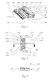
- Fig. 4 to 9 is a further embodiment of an electrical connector 200 according to the invention comprising two connector parts, namely a socket 201 and a plug 202 shown.
- Socket 201 and plug 202 are separate and in Fig. 5 shown in the assembled, interlocked state.
- 6 and 7 show a top view Fig. 4 respectively.
- Fig. 5 The Fig. 8 shows a section through the connector 200 along the in Fig. 7 dargfensiven section line BB.
- the Fig. 9 Finally, another perspective view of the socket 201 alone.
- the bushing 201 comprises a bushing body 204, which according to a conventional manner a plurality of connection means 205a-n (see 4 and FIG. 5 ), for example connecting sleeves or contact terminals, or contact openings 212a-n (see Fig. 9 ) having.
- the plug 202 includes a plug body 206, which is also provided according to known manner with a plurality of connection means and contacts, not shown in detail. The basic technical design of plugs, sockets, connection means and contacts are well known to those skilled in the art.
- the connector 200 further includes locking elements according to known per se.
- the locking elements in the example shown comprise a rocker arm 208 formed on an upper side 207 of the bushing 201, which engages in two assembled on the plug 202 locking lugs 213 upon assembly of the plug 202 and the sleeve 201, whereby between the plug 202 and the sleeve 201, a releasable latching connection arises.
- the rocker lever 208 is additionally secured by a formed on the plug 202 pin 214 in the locking connection.
- a resilient (ie elastic) sheet 210 is further integrally formed with the bushing body 204 and at a position above the rocker lever 208 as a spring element.
- the resilient arc 210 extends in a plane which is parallel to the insertion direction of the sleeve 201 and the plug 202. In the example shown, the sheet 210 is executed closed.
- a web-shaped mechanical stop 209 for the resilient sheet 210 is integrally formed. Between the plug body 206 and the web-shaped mechanical stop 209 there is a recess 215 through which the rocker lever 208 extends during the assembly of the two plug connection parts (see FIGS. 5, 7 and 8 ).
Abstract
Description
- Die Erfindung betrifft eine elektrische Steckverbindung, insbesondere für bewegte Vorrichtungen wie Kraftfahrzeuge und deren elektronische Bauteile, mit zwei zusammenfügbaren und ineinander einrastbaren Steckverbindungsteilen, wobei die beiden Steckverbindungsteile über Rastelemente in einer Rastverbindung vorzugsweise lösbar verbindbar sind.
- Elektrische Steckverbindungen sind nicht immer zufrieden stellend verrastet. Sie besitzen neben den klar erkennbaren elektrischen Zuständen "elektrischer Kontakt hergestellt" und "elektrischer Kontakt nicht hergestellt" eine unbegrenzte Anzahl mechanischer Zwischenstellungen. Diese unbegrenzte Anzahl an mechanischen Zwischenstellungen hat zur Folge, dass eine in der Produktion elektrisch unauffällige Steckverbindung später die elektrische Kontaktierung verlieren kann. Die Ursache liegt darin begründet, dass eine mechanische Zwischenstellung eine etwaig vorhandene Absicherung des Steckers in Form einer Verrastung, Verriegelung oder dergleichen unwirksam werden lässt.
- Bewegte Geräte und Vorrichtungen wie beispielsweise Kraftfahrzeuge weisen eine Vielzahl an elektrischen Bauelementen auf, die typischerweise über elektrische Steckverbindungen mit einem Kabelbaum verbunden sind. Bei einer nicht vollständig verrasteten elektrischen Steckverbindung kann während des Fahrbetriebs die elektrische Kontaktierung getrennt werden, was zu einem Ausfall von für die Funktionssicherheit eines Kraftfahrzeugs bedeutsamen Komponenten führen kann. Zusätzlich zu den Nachteilen in Bezug auf die Funktionsund Fahrsicherheit von Kraftfahrzeugen, lassen sich Ausfälle elektrischer Steckverbindungen häufig nicht ohne weiteres beheben und sind zudem ein häufiger Grund für Kundenreklamationen.
- Steckverbindungen besitzen üblicherweise sehr geringe Kontaktüberdeckungen, die typischerweise in einem Bereich von ca. 1 mm liegen. Für eine sichere Verrastung müssen die beiden Teile der Steckverbindung auf ca. 1/10 mm genau positioniert werden. Für einen Werker ist die mechanische Position der Steckverbindungsteile in dieser Genauigkeit nicht erfassbar.
- Bekannte Lösungen für das oben beschriebene Problem benötigen Maßnahmen wie Zusatzteile am Produkt selbst oder Zusatzeinrichtungen im Fertigungsprozess.
- Elektrische Steckverbindungen sind häufig durch Zusatzteile wie beispielsweise Verriegelungselemente, Schieber oder sonstige Arretierungsmittel gesichert. Solche Zusatzteile sind wirtschaftlich nachteilig, da sie einen zusätzlichen Montageschritt erforderlich machen und/oder konstruktiv aufwändig sind. Darüber hinaus lassen sich derart gesicherte Steckverbindungsteile, zum Beispiel beim späteren Austausch elektrischer Kraftfahrzeugkomponenten, nicht mehr ohne weiteres trennen.
- Auch Umgebungsbauteile sind zur Sicherung elektrischer Steckverbindungen schlecht geeignet, da sie die gewünschte Positionierung der Steckverbindungsteile nur ungenügend herstellen.
- Ein weiterer Lösungsansatz betrifft die Absicherung durch pneumatische Einrichtungen, die mechanisch derart auf die Steckerverbindung einwirken, dass eine Endlagenstellung bzw. Verrastung sichergestellt werden kann. Derartige Einrichtungen benötigen im Allgemeinen eine mit hohen Kosten verbundene Zykluszeit, sind aufgrund der Zugänglichkeit nur beschränkt einsetzbar und darüber hinaus kostenintensiv in der Anschaffung und Erhaltung.
- Absicherungen für elektrische Steckverbindungen mit Hilfe von Kamerasystemen benötigen spezielle Einhausungen und Abschottungen, um den Einfluss von Fremdlicht zu eliminieren. Ferner können solche Systeme eine ungenügend positionierte Steckverbindung nicht automatisch nachbessern, weshalb der Fertigungsvorgang nicht in einem Durchlauf erledigt werden kann. Eine nicht vollständig eingerastete Steckverbindung muss in einem zusätzlichen Schritt ausgebessert werden, der zusätzliche Kosten verursacht. Außerdem sind sie kostenintensiv in der Errichtung und Inbetriebnahme.
- Aus der
EP1698026 B1 ist ein Stecker mit einem metallischen Gehäuse bekannt, an dem einstückig Mittel zur Verriegelung angebracht sind, durch deren Betätigungsmittel visuell erkennbar ist, ob sich der Stecker in einer Entriegelungs- oder Verriegelungsstellung befindet. Neben dem sehr filigranen Aufbau ist nach dem Zusammenstecken der Steckverbindung eine optische Kontrolle notwendig. - Aus der
EP0660451 A2 ist eine zweiteilige Steckerverbindung bekannt, deren erster Teil eine Rastnase und deren zweiter Teil ein Gegenstück aufweist, die derart zusammenwirken, dass die beiden Teile zu einer Relativbewegung gezwungen werden. Neben der fragilen Ausführung ist ein weiterer Arbeitsschritt notwendig, der für eine sichere Verbindung der Steckerteile sorgt. - Die
EP 1 891 711 B1 offenbart einen elektrischen Steckverbinder für ein Kraftfahrzeug, der zwei zusammenfügbare Steckverbinderteile aufweist, wobei nach dem Zusammenfügen der Steckverbinderteile das erste Steckverbinderteil über Rastelemente mit dem zweiten Steckverbinderteil verbunden ist, mit Arretierungsmitteln zur Sicherung der Rastverbindung zwischen den Steckverbinderteilen. Die Arretierungsmittel sind mit einem Verbindungselement befestigt, das gegenüber dem ersten Steckverbinderteil mindestens zwei Raststellungen einnehmen kann. Nachteilig an diesem Steckverbinder ist jedoch, dass nach dem Einrasten in die erste Raststellung Zwischenstellungen nicht ausgeschlossen werden können, weshalb eine sichere elektrische Verbindung nicht gewährleistet werden kann. - Es ist eine Aufgabe der Erfindung, eine elektrische Steckverbindung, insbesondere für bewegte Geräte und Vorrichtungen wie Kraftfahrzeuge und deren elektrische Komponenten, bereitzustellen, die das Erkennen einer mechanischen Zwischenstellung auf einfache und Kosten schonende Art und Weise ermöglicht und die sich zudem technisch leicht realisieren lässt.
- Diese Aufgabe wird durch eine elektrische Steckverbindung der eingangs genannten Art gelöst, die erfindungsgemäß durch zumindest ein an einem der beiden Steckverbindungsteile direkt angeformtes oder als Anbauteil angeordnetes und gegen die Rastverbindung bzw. Steckrichtung zwischen den beiden Steckverbindungsteilen federnd wirkendes Federelement gekennzeichnet ist.
- Erfindungsgemäß wird im Bereich der Steckverbindung ein Federelement ausgebildet, das bei Nichtverrasten der Steckverbindungsteile (z.B. Stecker, Gegenstecker, Buchse) diese entgegen der Steckrichtung auseinanderdrückt. Im Falle einer mechanischen Zwischenstellung, d.h. einer nicht vollständig verrasteten Steckverbindung, bewirkt dies die elektrische Trennung eines, mehrerer oder aller Kontakte. Dadurch wird eine mechanische Zwischenstellung elektrisch erkennbar.
- Das Federelement ist entweder direkt an einem der beiden Steckverbindungsteile nach an sich bekannter Art angeformt, z.B. mittels Anschweißen oder, vorzugsweise einstückig, durch Mitformen/Spritzgießen bei der Herstellung des Steckverbindungsteils. Dadurch ist eine einfache und kostengünstige Herstellung möglich. Zweckmäßigerweise sind Federelement und Steckverbindungsteil aus Kunststoff gefertigt.
- Alternativ dazu ist das Federelement als Anbauteil an einem der beiden Steckverbindungsteile angeordnet und vorzugsweise ist das Federelement mit dem Steckverbindungsteil fest verbunden. Unter "Anbauteil" ist zu verstehen, dass das Federelement als Zusatzteil auf dem Steckverbindungsteil aufgebracht ist. Dies ist insbesondere dann von Vorteil, wenn das Federelement aus einem anderen Material wie das Steckverbindungsteil besteht. Beispielsweise kann das Federelement als ein aus Federstahl hergestelltes Metallteil ausgeführt sein, das beim Herstellen eines Kunststoff-Steckverbindungsteils nach an sich bekannter Art in dieses eingebettet wird.
- Dank der Erfindung wird die vollständige Verrastung der Steckverbindung über die elektrischen Kontakte eindeutig prüfbar und die Absicherung kann über die ohnehin bei jedem Einzelteil durchgeführte elektrische Prüfung durchgeführt werden. Dadurch werden zusätzliche Maßnahmen wie oben beschrieben (d.h. Zusatzteile am Produkt oder Zusatzeinrichtungen im Fertigungsprozess) überflüssig. Ferner ist es nicht erforderlich, einen Zusatzteil wie beispielsweise einen Schieber, ein Verriegelungselement oder dergleichen zu betätigen, um die Sicherung zu aktivieren. Dies bringt einen wesentlichen wirtschaftlichen Vorteil mit sich. Darüber hinaus ist die erfindungsgemäße elektrische Steckverbindung technisch einfach und daher kostengünstig zu realisieren.
- Die Erfindung kommt mit besonderen Vorteilen bei bewegten Geräten, Gegenständen und Vorrichtungen, insbesondere bei Kraftfahrzeugen und deren elektronischen Bauteilen und Komponenten, zur Anwendung, da sich bei diesen aufgrund der Bewegung nicht zufrieden stellend verrastete Steckverbindungen besonders leicht lösen. Besonders vorteilhaft ist die Erfindung für Kraftfahrzeuge und deren elektronische Bauteile hinsichtlich deren Funktionssicherheit.
- Der Begriff "federnd wirkendes Federelement" wie hierin verwendet bezieht sich auf Federelemente, die einerseits eine entgegen die Verrastung wirkende Federkraft ausüben, die ausreichend ist, um die Steckverbindung bei einer mechanischen Zwischenstellung zu lösen. Andererseits sollte diese Federkraft nicht so stark sein, dass eine vollständige Verrastung der Steckverbindungsteile verhindert wird. Die Federkraft wirkt vorzugsweise ab dem Zeitpunkt/der Steckerstellung, ab dem/der eine elektrische Zwischenstellung möglich ist.
- Das Federelement ist vorzugsweise aus Kunststoff und vorzugsweise einstückig mit dem Steckverbindungsteil gefertigt. Auch wenn aus Kunststoff gefertigte Federelemente bevorzugt sind, kann das Federelement auch aus anderen elastischen Materialien wie z.B. Federstahl hergestellt sein.
- Rastelemente, welche zwei Steckverbindungsteile in einer Rastverbindung, vorzugsweise lösbar, verbinden, sind hinlänglich bekannt. Beispielsweise kann es sich hierbei um einen Wipphebel handeln, der an einem der beiden Steckverbindungsteile angeformt ist und der in eine auf dem anderen Steckverbindungsteil angeformte Rastnase einrastet.
- Bei einer besonders zweckmäßigen Weiterbildung der erfindungsgemäßen elektrischen Steckverbindung ist das zumindest eine Federelement an einem der beiden Steckverbindungsteile direkt angeformt oder als Anbauteil angeordnet und an dem jeweils anderen Steckverbindungsteil ist zumindest ein Gegenelement direkt angeformt oder als Anbauteil angeordnet, wobei das zumindest eine Gegenelement gegen das zumindest eine Federelement einen mechanischen Widerstand ausübt.
- Das Gegenelement ist entweder direkt an dem jeweils anderen der beiden Steckverbindungsteile nach an sich bekannter Art angeformt, z.B. mittels Anschweißen oder, vorzugsweise einstückig, durch Mitformen/Spritzgießen bei der Herstellung des Steckverbindungsteils. Dadurch ist eine einfache und kostengünstige Herstellung möglich. Zweckmäßigerweise sind Gegenelement und Steckverbindungsteil aus Kunststoff gefertigt.
- Alternativ dazu ist das Gegenelement als Anbauteil an dem jeweils anderen der beiden Steckverbindungsteile angeordnet und vorzugsweise ist das Gegenelement mit dem jeweils anderen Steckverbindungsteil fest verbunden. Unter "Anbauteil" ist zu verstehen, dass das Gegenelement als Zusatzteil auf dem Steckverbindungsteil aufgebracht ist. Dies ist insbesondere dann von Vorteil, wenn das Gegenelement aus einem anderen Material wie das Steckverbindungsteil besteht. Beispielsweise kann das Gegenelement als Metallteil ausgeführt sein, das beim Herstellen eines Kunststoff-Steckverbindungsteils nach an sich bekannter Art in dieses eingebettet wird.
- Bei einer sehr einfach zu realisierenden Variante ist das zumindest eine Federelement direkt an einem der beiden Steckverbindungsteile angeformt und das zumindest eine Gegenelement ist direkt an dem jeweils anderen Steckverbindungsteil angeformt.
- Für eine einfache und kostengünstige Herstellung ist es günstig, wenn das zumindest eine Federelement einstückig an einem der beiden Steckverbindungsteile angeformt ist und das zumindest eine Gegenelement einstückig am jeweils anderen Steckverbindungsteil angeformt ist.
- Bei einer ersten vorteilhaften Ausführungsform der erfindungsgemäßen elektrischen Steckverbindung ist das zumindest eine Gegenelement als mechanischer Anschlag ausgebildet. Mit Vorteil ist das zumindest eine Federelement als ein federnder Bogen ausgebildet, da ein solcher mit wenig konstruktivem Aufwand herstellbar ist. Vorzugsweise erstreckt sich der federnde Bogen im Wesentlichen über die gesamte Breite des Steckverbindungsteils, wodurch eine gleichmäßige Verteilung der Federkraft über die gesamte Steckverbindungsteilbreite und somit ein gleichmäßiges Zusammenfügen der Steckverbindung möglich ist. Der federnde Bogen übt beim Auftreffen auf den mechanischen Anschlag eine Kraft entgegen der Steckrichtung der Steckverbindungsteile aus und verhindert auf diese Weise mechanische Zwischenstellungen aufgrund nicht ausreichend verrasteter Steckverbindungsteile. Eine Steckverbindung gemäß dieser Ausführungsform lässt sich bei Bedarf, z.B. bei einem Austausch von Vorrichtungskomponenten, mit einfachen Handgriffen wieder lösen. Der federnde Bogen kann offen oder geschlossen sein. Vorzugsweise ist der Bogen geschlossen, da ein stabilerer Kontakt zwischen dem federnden Bogen und dem mechanischen Anschlag möglich ist. Damit die elektrische Steckverbindung möglichst Raum sparend dimensioniert ist, ist es von Vorteil, wenn der federnde Bogen in einer Ebene verläuft, die parallel zur Steckrichtung der Steckverbindungsteile ist. Aus demselben Grund verläuft auch der mechanische Anschlag mit Vorteil in einer Ebene, die parallel zur Steckrichtung der Steckverbindungsteile ist.
- Bei einer weiteren vorteilhaften und einfach zu realisierenden Ausführungsform ist das zumindest eine Gegenelement als Zungenelement ausgebildet und das zumindest eine Federelement umfasst parallel zu dem Zungenelement verlaufende federnde Schenkel, wobei die federnden Schenkel eine Aufnahme ausbilden, in der das Zungenelement, vorzugsweise lösbar, einschnappbar ist. Bei dieser Ausführungsform bewirkt das zumindest eine Zungenelement beim Zusammenfügen der Steckverbindungsteile zuerst eine Kraft entgegen der Steckrichtung der Steckverbindungsteile, indem es gegen die federnden Schenkel einen mechanischen Widerstand ausübt. Sobald das Zungenelement jedoch weit genug in die Aufnahme vorgedrungen ist, wird die Kraft in Steckrichtung der Steckverbindungsteile ausgeübt, was schlussendlich zu einem vollständigen Einschnappen (Einrasten) des Zungenelements in der durch die federnden Schenkel definierten Aufnahme führt. Die federnden Schenkel sind zum besseren Einrasten des Zungenelements in der Aufnahme vorzugsweise hakenförmig ausgebildet. Bei dieser Ausführungsform wird durch das Zusammenwirken des Zungenelements und der federnden Schenkel einerseits eine mechanische Zwischenstellung elektrisch erkennbar gemacht und verhindert, weil nur bei vollständiger Verrastung der Steckverbindungsteile ein elektrischer Kontakt zustande kommt. Andererseits wird durch das Zusammenwirken die Steckverbindung zusätzlich zu den ebenfalls vorgesehenen Rastelementen gesichert.
- Da die erfindungsgemäße elektrische Steckverbindung besonders vorteilhaft in Kraftfahrzeugen sowie in deren elektronischen Komponenten zur Anwendung kommt, bezieht sich ein weiterer Aspekt der Erfindung auf ein Kraftfahrzeug, das zumindest eine elektrische Steckverbindung wie oben und in den Ansprüchen definiert umfasst.
- Der Gegenstand der Erfindung bezieht sich ferner auf eine Beleuchtungseinrichtung für ein Kraftfahrzeug umfassend zumindest eine elektrische Steckverbindung wie oben und in den Ansprüchen definiert. Der Begriff "Beleuchtungseinrichtung für ein Kraftfahrzeug" umfasst alle Arten von Kraftfahrzeugscheinwerfern, insbesondere Frontscheinwerfer und Heckleuchten.
- Die Erfindung wird im Folgenden anhand von nicht einschränkenden Beispielen gemäß der beiliegenden Zeichnung näher beschrieben, in der:
-
Fig. 1 eine perspektivische Ansicht einer elektrischen Steckverbindung einer Ausführungsform gemäß der Erfindung ist, wobei Stecker und Buchse getrennt dargestellt sind, -
Fig. 2 eine Draufsicht auf die elektrische Steckverbindung gemäßFig. 1 ist, wobei Stecker und Buchse im zusammengefügten und ineinander eingerasteten Zustand dargestellt sind, -
Fig. 3 ein Schnitt durch die elektrische Steckverbindung entlang der Schnittlinie A-A aus derFig. 2 ist, -
Fig. 4 eine perspektivische Ansicht einer elektrischen Steckverbindung einer weiteren Ausführungsform gemäß der Erfindung ist, wobei Stecker und Buchse getrennt dargestellt sind, -
Fig. 5 eine perspektivische Ansicht der elektrischen Steckverbindung ausFig. 4 ist, wobei Stecker und Buchse im zusammengefügten und ineinander eingerasteten Zustand dargestellt sind, -
Fig. 6 eine Draufsicht auf die Darstellung inFig. 4 ist, -
Fig. 7 eine Draufsicht auf die Darstellung inFig. 5 ist, -
Fig. 8 ein Schnitt durch die elektrische Steckverbindung entlang der Schnittlinie B-B gemäß derFig. 7 ist, und -
Fig. 9 eine weitere perspektivische Ansicht der Buchse gemäß derFig. 4 ist. - In den
Fig. 1 bis 3 ist eine erste Ausführungsform einer erfindungsgemäßen elektrischen Steckverbindung 100 umfassend zwei Steckverbindungsteile, nämlich einen Stecker 101 und eine Buchse 102 dargestellt. In derFig. 1 sind Stecker 101 und Buchse 102 getrennt und inFig. 2 sind sie im zusammengefügten, ineinander eingerasteten Zustand dargestellt. DieFig. 3 zeigt einen Schnitt durch die Steckverbindung 100 entlang der inFig. 2 dargstellten Schnittlinie A-A. Der Stecker 101 umfasst einen Steckerkörper 104, der nach an sich bekannter Art eine Vielzahl von Anschlussmitteln 105 a-n, beispielsweise Anschlusshülsen oder Kontaktklemmen, sowie Kontakte aufweist. Die Buchse 102 umfasst einen Buchsenkörper 106, der gleichfalls nach an sich bekannter Art mit einer nicht näher dargestellten Vielzahl von Anschlussmitteln und Kontakten versehen ist. Die grundlegende technische Ausführung von Steckern, Buchsen, Anschlussmitteln und Kontakten sind dem einschlägigen Fachmann hinlänglich bekannt. Die Steckverbindung 100 weist ferner Rastelemente nach an sich bekannter Art auf. Die Rastelemente im gezeigten Beispiel umfassen einen an einer Oberseite 107 des Steckers 101 angeformten Wipphebel 108, der beim Zusammenfügen des Steckers 101 und der Buchse 102 in eine an der Buchse 102 angeformte Rastnase 113 einrastet, wodurch zwischen dem Stecker 101 und Buchse 102 eine lösbare Rastverbindung entsteht. - Auf der Oberseite 107 des Steckers 101 sind links und rechts des Wipphebels 108 ferner zwei Zungenelemente 109a und 109b angeformt. Die Zungenelemente 109a, 109b verlaufen in einer Ebene, die parallel zur Steckrichtung von Stecker 101 und Buchse 102 verläuft. An der Buchse 102 sind parallel zu dem Zungenelement verlaufende federnde hakenförmige Schenkel 110a, 110b, 110c und 110d angeformt. Je zwei dieser hakenförmigen Schenkel - im gezeigten Beispiel die Schenkel 110a und 110b bzw. 110c und 110d - definieren eine Aufnahme 111a bzw. 111b, in der das jeweilige korrespondierende Zungenelement 109a bzw. 109b einschnappbar ist. Bei der in den
Fig. 1 bis 3 gezeigten Ausführungsform bewirken die Zungenelemente 109a, 109b beim Zusammenfügen der beiden Steckverbindungsteile (Stecker 101, Buchse 102) zuerst eine Kraft entgegen der Steckrichtung der beiden Steckverbindungsteile, indem sie gegen die federnden Schenkel 110a-d einen mechanischen Widerstand ausüben. Sobald das jeweilige Zungenelement 109a bzw. 109b jedoch weit genug in die Aufnahme 111a bzw. 111b vorgedrungen ist, wird die Kraft in Steckrichtung der Steckverbindungsteile ausgeübt, was schlussendlich zu einem vollständigen Einschnappen (Einrasten) des jeweiligen Zungenelements 109a bzw. 109b in der jeweiligen durch die federnden Schenkel 110a-d definierten Aufnahme 111a bzw. 111b führt (sieheFig. 2 ). Bei dieser Ausführungsform wird durch das Zusammenwirken der Zungenelemente 109a, 109b und der federnden Schenkel 110a-d folglich einerseits eine mechanische Zwischenstellung der Steckverbindung 100 elektrisch erkennbar gemacht, da nur bei vollständiger Verrastung des Steckers 101 und der Buchse 102 ein elektrischer Kontakt zustande kommt. Andererseits wird die elektrische Steckverbindung 100 nicht nur durch die Rastelemente, sondern zusätzlich auch durch das Zusammenwirken der Zungenelemente 109a, 109b und der federnden Schenkel 110a-d gesichert. - In den
Fig. 4 bis 9 ist eine weitere Ausführungsform einer erfindungsgemäßen elektrischen Steckverbindung 200 umfassend zwei Steckverbindungsteile, nämlich eine Buchse 201 und einen Stecker 202 dargestellt. In derFig. 4 sind Buchse 201 und Stecker 202 getrennt und inFig. 5 im zusammengefügten, ineinander eingerasteten Zustand dargestellt.Fig. 6 und 7 zeigen eine Draufsicht aufFig. 4 bzw.Fig. 5 . DieFig. 8 zeigt einen Schnitt durch die Steckverbindung 200 entlang der inFig. 7 dargstellten Schnittlinie B-B. DieFig. 9 schließlich zeigt eine weitere perspektivische Darstellung der Buchse 201 allein. - Die Buchse 201 umfasst einen Buchsenkörper 204, der nach an sich bekannter Art eine Vielzahl von Anschlussmitteln 205a-n (siehe
Fig. 4 und Fig. 5 ), beispielsweise Anschlusshülsen oder Kontaktklemmen, bzw. Kontaktöffnungen 212a-n (sieheFig. 9 ) aufweist. Der Stecker 202 umfasst einen Steckerkörper 206, der gleichfalls nach an sich bekannter Art mit einer nicht näher dargestellten Vielzahl von Anschlussmitteln und Kontakten versehen ist. Die grundlegende technische Ausführung von Steckern, Buchsen, Anschlussmitteln und Kontakten sind dem einschlägigen Fachmann hinlänglich bekannt. Die Steckverbindung 200 weist ferner Rastelemente nach an sich bekannter Art auf. Die Rastelemente im gezeigten Beispiel umfassen einen an einer Oberseite 207 der Buchse 201 angeformten Wipphebel 208, der beim Zusammenfügen des Steckers 202 und der Buchse 201 in zwei am Stecker 202 angeformte Rastnasen 213 einrastet, wodurch zwischen dem Stecker 202 und der Buchse 201 eine lösbare Rastverbindung entsteht. Der Wipphebel 208 wird noch zusätzlich durch einen auf dem Stecker 202 angeformten Stift 214 in der Rastverbindung gesichert. - Auf der Oberseite 207 der Buchse 201 ist ferner einstückig mit dem Buchsenkörper 204 und an einer Position oberhalb des Wipphebels 208 als Federelement ein federnder (d.h. elastischer) Bogen 210 angeformt. Der federnde Bogen 210 verläuft dabei in einer Ebene, die parallel zur Steckrichtung der Buchse 201 und des Steckers 202 ist. Im gezeigten Beispiel ist der Bogen 210 geschlossen ausgeführt. Am Stecker 202 ist ein stegförmiger mechanischer Anschlag 209 für den federnden Bogen 210 einstückig angeformt. Zwischen dem Steckerkörper 206 und dem stegförmigen mechanischen Anschlag 209 befindet sich eine Ausnehmung 215, durch welche sich beim Zusammenfügen der beiden Steckverbindungsteile der Wipphebel 208 erstreckt (siehe
Fig. 5, Fig. 7 und Fig. 8 ). Beim Zusammenfügen des Steckers 202 und der Buchse 201 trifft der federnde Bogen 210 auf den mechanischen Anschlag 209 auf, übt dabei eine Kraft entgegen der Steckrichtung der beiden Steckverbindungsteile aus und verhindert auf diese Weise mechanische Zwischenstellungen aufgrund nicht ausreichend verrasteter Steckverbindungsteile. Eine mechanische Zwischenstellung wird durch die Kraft des federnden Bogens 210 entgegen der Steckrichtung somit elektrisch erkennbar, da nur bei einer vollständigen Verrastung des Steckers 202 und der Buchse 201 ein stabiler elektrischer Kontakt zustande kommt. Eine vollständig verrastete Steckverbindung 200 ist in denFig. 5 und 7 gezeigt. - Die gezeigten Beispiele sind nur einige unter vielen und nicht als einschränkend zu betrachten.
Claims (10)
- Elektrische Steckverbindung (100, 200) mit zwei zusammenfügbaren und ineinander einrastbaren Steckverbindungsteilen (101, 102, 201, 202), wobei die beiden Steckverbindungsteile über Rastelemente (108, 113, 208, 213) in einer Rastverbindung vorzugsweise lösbar verbindbar sind,
gekennzeichnet durch
zumindest ein an einem der beiden Steckverbindungsteile direkt angeformtes oder als Anbauteil angeordnetes und gegen die Rastverbindung zwischen den beiden Steckverbindungsteilen federnd wirkendes Federelement (110a, 110b, 110c, 110d, 210). - Elektrische Steckverbindung (100, 200) nach Anspruch 1, dadurch gekennzeichnet, dass an dem jeweils anderen Steckverbindungsteil zumindest ein Gegenelement (109a, 109b, 209) direkt angeformt oder als Anbauteil angeordnet ist, wobei das zumindest eine Gegenelement gegen das zumindest eine Federelement einen mechanischen Widerstand ausübt.
- Elektrische Steckverbindung (100, 200) nach Anspruch 2, dadurch gekennzeichnet, dass das zumindest eine Federelement (110a, 110b, 110c, 110d, 210) direkt an einem der beiden Steckverbindungsteile angeformt ist und das zumindest eine Gegenelement (109a, 109b, 209) direkt an dem jeweils anderen Steckverbindungsteil angeformt ist.
- Elektrische Steckverbindung (100, 200) nach Anspruch 3, dadurch gekennzeichnet, dass das zumindest eine Federelement (110a, 110b, 110c, 110d, 210) einstückig an einem der beiden Steckverbindungsteile angeformt ist und das zumindest eine Gegenelement (109a, 109b, 209) einstückig am jeweils anderen Steckverbindungsteil angeformt ist.
- Elektrische Steckverbindung (200) nach einem der Ansprüche 2 bis 4, dadurch gekennzeichnet, dass das zumindest eine Gegenelement als mechanischer Anschlag (209) ausgebildet ist.
- Elektrische Steckverbindung (200) nach Anspruch 5, dadurch gekennzeichnet, dass das zumindest eine Federelement als ein federnder Bogen (210), vorzugsweise geschlossener Bogen, ausgebildet ist.
- Elektrische Steckverbindung (200) nach Anspruch 6, dadurch gekennzeichnet, dass der federnde Bogen (210) in einer Ebene verläuft, die parallel zur Steckrichtung der Steckverbindungsteile ist.
- Elektrische Steckverbindung (100) nach einem der Ansprüche 2 bis 4, dadurch gekennzeichnet, dass das zumindest eine Gegenelement als Zungenelement (109a, 109b) ausgebildet ist und das zumindest eine Federelement parallel zu dem Zungenelement verlaufende federnde Schenkel (110a, 110b, 110c, 110d) umfasst, wobei die federnden Schenkel eine Aufnahme (111a, 111b) ausbilden, in der das Zungenelement (109a, 109b) vorzugsweise lösbar einschnappbar ist.
- Kraftfahrzeug umfassend zumindest eine elektrische Steckverbindung (100, 200) nach einem der Ansprüche 1 bis 8.
- Beleuchtungseinrichtung für ein Kraftfahrzeug umfassend zumindest eine elektrische Steckverbindung (100,200) nach einem der Ansprüche 1 bis 8.
Applications Claiming Priority (1)
| Application Number | Priority Date | Filing Date | Title |
|---|---|---|---|
| ATA50653/2013A AT514888B1 (de) | 2013-10-10 | 2013-10-10 | Elektrische Steckverbindung mit einem Federelement sowie Beleuchtungseinrichtung mit Steckverbindung |
Publications (2)
| Publication Number | Publication Date |
|---|---|
| EP2860826A1 true EP2860826A1 (de) | 2015-04-15 |
| EP2860826B1 EP2860826B1 (de) | 2017-06-07 |
Family
ID=51570444
Family Applications (1)
| Application Number | Title | Priority Date | Filing Date |
|---|---|---|---|
| EP14186017.1A Active EP2860826B1 (de) | 2013-10-10 | 2014-09-23 | Elektrische Steckverbindung mit einem Federelement |
Country Status (3)
| Country | Link |
|---|---|
| EP (1) | EP2860826B1 (de) |
| CN (1) | CN104577514B (de) |
| AT (1) | AT514888B1 (de) |
Citations (8)
| Publication number | Priority date | Publication date | Assignee | Title |
|---|---|---|---|---|
| EP0119013A2 (de) * | 1983-02-14 | 1984-09-19 | Nec Corporation | Verbinder mit Mechanismus zum Kuppeln oder Entkuppeln einer Mehrzahl von Blöcken |
| EP0660451A2 (de) | 1993-12-27 | 1995-06-28 | Sumitomo Wiring Systems, Ltd. | Steckverbinder |
| EP0758150A2 (de) * | 1995-08-09 | 1997-02-12 | SUMITOMO WIRING SYSTEMS, Ltd. | Verbindungseinrichtung mit einem Federmechanismus |
| EP0954061A1 (de) * | 1998-04-27 | 1999-11-03 | Sumitomo Wiring Systems, Ltd. | Ein Verbinder |
| EP1137117A2 (de) * | 2000-03-21 | 2001-09-26 | F.C.I. - Framatome Connectors International | Elektrischer Verbindungsstecker |
| EP1698026B1 (de) | 2003-12-24 | 2008-03-19 | Hella KGaA Hueck & Co. | Stecker |
| EP1891711B1 (de) | 2005-06-17 | 2012-03-14 | Kostal Kontakt Systeme GmbH | Elektrischer steckverbinder für ein kraftfahrzeug |
| DE102012100615A1 (de) * | 2012-01-25 | 2013-07-25 | HARTING Electronics GmbH | Steckverbindungssystem für Steckverbinder |
Family Cites Families (3)
| Publication number | Priority date | Publication date | Assignee | Title |
|---|---|---|---|---|
| JP3155176B2 (ja) * | 1995-08-09 | 2001-04-09 | 住友電装株式会社 | コネクタ |
| JP3741356B2 (ja) * | 2000-05-29 | 2006-02-01 | 矢崎総業株式会社 | 半嵌合防止コネクタ |
| JP2001345147A (ja) * | 2000-05-31 | 2001-12-14 | Yazaki Corp | 半嵌合防止コネクタ |
-
2013
- 2013-10-10 AT ATA50653/2013A patent/AT514888B1/de not_active IP Right Cessation
-
2014
- 2014-09-23 EP EP14186017.1A patent/EP2860826B1/de active Active
- 2014-10-10 CN CN201410529071.0A patent/CN104577514B/zh active Active
Patent Citations (8)
| Publication number | Priority date | Publication date | Assignee | Title |
|---|---|---|---|---|
| EP0119013A2 (de) * | 1983-02-14 | 1984-09-19 | Nec Corporation | Verbinder mit Mechanismus zum Kuppeln oder Entkuppeln einer Mehrzahl von Blöcken |
| EP0660451A2 (de) | 1993-12-27 | 1995-06-28 | Sumitomo Wiring Systems, Ltd. | Steckverbinder |
| EP0758150A2 (de) * | 1995-08-09 | 1997-02-12 | SUMITOMO WIRING SYSTEMS, Ltd. | Verbindungseinrichtung mit einem Federmechanismus |
| EP0954061A1 (de) * | 1998-04-27 | 1999-11-03 | Sumitomo Wiring Systems, Ltd. | Ein Verbinder |
| EP1137117A2 (de) * | 2000-03-21 | 2001-09-26 | F.C.I. - Framatome Connectors International | Elektrischer Verbindungsstecker |
| EP1698026B1 (de) | 2003-12-24 | 2008-03-19 | Hella KGaA Hueck & Co. | Stecker |
| EP1891711B1 (de) | 2005-06-17 | 2012-03-14 | Kostal Kontakt Systeme GmbH | Elektrischer steckverbinder für ein kraftfahrzeug |
| DE102012100615A1 (de) * | 2012-01-25 | 2013-07-25 | HARTING Electronics GmbH | Steckverbindungssystem für Steckverbinder |
Also Published As
| Publication number | Publication date |
|---|---|
| CN104577514A (zh) | 2015-04-29 |
| AT514888A1 (de) | 2015-04-15 |
| EP2860826B1 (de) | 2017-06-07 |
| CN104577514B (zh) | 2018-05-18 |
| AT514888B1 (de) | 2015-09-15 |
Similar Documents
| Publication | Publication Date | Title |
|---|---|---|
| DE4228531C2 (de) | Steckverbinderanordnung mit ersten und zweiten Steckverbinderteilen | |
| DE102012209298B4 (de) | Elektrischer Steckverbinder, Steckverbinderanordnung sowie Verfahren zum Montieren des Steckverbinders | |
| EP2822108B1 (de) | Stromschienenadapter und Anordnung mit Stromschienenadapter und Stromschiene | |
| EP1662620A2 (de) | Elektrische Steckverbindung | |
| DE102008028933A1 (de) | Stromkreisunterbrechungsvorrichtung | |
| DE112019002139T5 (de) | Verstärktes Positionssicherungselement | |
| DE102009059685A1 (de) | Steckerelement mit einem Verriegelungsmechanismus | |
| DE102009022094A1 (de) | Stapelverbinder | |
| EP1856709A1 (de) | Elektromechanisches schaltgerät | |
| DE10003267C2 (de) | Stromkreisunterbrechereinrichtung | |
| DE10259067B4 (de) | Verbinder und Verfahren zum Montieren eines Verbindergehäuses an einer Platte | |
| EP3073577B1 (de) | Steckerteil, steckverbindung und verfahren zum herstellen eines steckerteils | |
| DE102014117062A1 (de) | Federkraftklemme | |
| DE19855824A1 (de) | Verbindungserkennungsmechanismus für eine Steckverbindung aus einem Stecker und einer Steckbuchse | |
| DE69834079T2 (de) | Selbstausrichtender elektrischer Steckerverbinder | |
| EP1665480B1 (de) | Vorrichtung zum herstellen einer elektrischen verbindung | |
| EP1811609B1 (de) | Elektrischer Verbinder, elektrisches Verbindungssystem und Verfahren zur Bildung eines elektrischen Verbindungssystems | |
| DE10304847B4 (de) | Verbinder | |
| EP2860826B1 (de) | Elektrische Steckverbindung mit einem Federelement | |
| DE102009014634A1 (de) | LIF-Stecker | |
| DE3604548C3 (de) | Elektrische Verbinderanordnung mit einem Steuerflächensystem | |
| DE3435823C2 (de) | Verfahren zur Herstellung von Klinkensteckerbuchsen | |
| DE60006734T2 (de) | Unterbrecher | |
| DE69928878T2 (de) | Sicherheitsverbindungsvorrichtung, insbesondere für modulare elektrische Geräte | |
| DE102012218028A1 (de) | Stecker und Bausatz für einen Stecker |
Legal Events
| Date | Code | Title | Description |
|---|---|---|---|
| PUAI | Public reference made under article 153(3) epc to a published international application that has entered the european phase |
Free format text: ORIGINAL CODE: 0009012 |
|
| 17P | Request for examination filed |
Effective date: 20140923 |
|
| AK | Designated contracting states |
Kind code of ref document: A1 Designated state(s): AL AT BE BG CH CY CZ DE DK EE ES FI FR GB GR HR HU IE IS IT LI LT LU LV MC MK MT NL NO PL PT RO RS SE SI SK SM TR |
|
| AX | Request for extension of the european patent |
Extension state: BA ME |
|
| R17P | Request for examination filed (corrected) |
Effective date: 20151012 |
|
| RBV | Designated contracting states (corrected) |
Designated state(s): AL AT BE BG CH CY CZ DE DK EE ES FI FR GB GR HR HU IE IS IT LI LT LU LV MC MK MT NL NO PL PT RO RS SE SI SK SM TR |
|
| 17Q | First examination report despatched |
Effective date: 20160405 |
|
| RAP1 | Party data changed (applicant data changed or rights of an application transferred) |
Owner name: ZKW GROUP GMBH |
|
| GRAP | Despatch of communication of intention to grant a patent |
Free format text: ORIGINAL CODE: EPIDOSNIGR1 |
|
| INTG | Intention to grant announced |
Effective date: 20170303 |
|
| GRAS | Grant fee paid |
Free format text: ORIGINAL CODE: EPIDOSNIGR3 |
|
| AK | Designated contracting states |
Kind code of ref document: B1 Designated state(s): AL AT BE BG CH CY CZ DE DK EE ES FI FR GB GR HR HU IE IS IT LI LT LU LV MC MK MT NL NO PL PT RO RS SE SI SK SM TR |
|
| REG | Reference to a national code |
Ref country code: GB Ref legal event code: FG4D Free format text: NOT ENGLISH |
|
| GRAA | (expected) grant |
Free format text: ORIGINAL CODE: 0009210 |
|
| REG | Reference to a national code |
Ref country code: CH Ref legal event code: EP Ref country code: AT Ref legal event code: REF Ref document number: 899865 Country of ref document: AT Kind code of ref document: T Effective date: 20170615 |
|
| REG | Reference to a national code |
Ref country code: IE Ref legal event code: FG4D Free format text: LANGUAGE OF EP DOCUMENT: GERMAN |
|
| REG | Reference to a national code |
Ref country code: DE Ref legal event code: R096 Ref document number: 502014004081 Country of ref document: DE |
|
| REG | Reference to a national code |
Ref country code: FR Ref legal event code: PLFP Year of fee payment: 4 |
|
| REG | Reference to a national code |
Ref country code: NL Ref legal event code: MP Effective date: 20170607 |
|
| REG | Reference to a national code |
Ref country code: LT Ref legal event code: MG4D |
|
| PG25 | Lapsed in a contracting state [announced via postgrant information from national office to epo] |
Ref country code: ES Free format text: LAPSE BECAUSE OF FAILURE TO SUBMIT A TRANSLATION OF THE DESCRIPTION OR TO PAY THE FEE WITHIN THE PRESCRIBED TIME-LIMIT Effective date: 20170607 Ref country code: LT Free format text: LAPSE BECAUSE OF FAILURE TO SUBMIT A TRANSLATION OF THE DESCRIPTION OR TO PAY THE FEE WITHIN THE PRESCRIBED TIME-LIMIT Effective date: 20170607 Ref country code: FI Free format text: LAPSE BECAUSE OF FAILURE TO SUBMIT A TRANSLATION OF THE DESCRIPTION OR TO PAY THE FEE WITHIN THE PRESCRIBED TIME-LIMIT Effective date: 20170607 Ref country code: HR Free format text: LAPSE BECAUSE OF FAILURE TO SUBMIT A TRANSLATION OF THE DESCRIPTION OR TO PAY THE FEE WITHIN THE PRESCRIBED TIME-LIMIT Effective date: 20170607 Ref country code: GR Free format text: LAPSE BECAUSE OF FAILURE TO SUBMIT A TRANSLATION OF THE DESCRIPTION OR TO PAY THE FEE WITHIN THE PRESCRIBED TIME-LIMIT Effective date: 20170908 Ref country code: NO Free format text: LAPSE BECAUSE OF FAILURE TO SUBMIT A TRANSLATION OF THE DESCRIPTION OR TO PAY THE FEE WITHIN THE PRESCRIBED TIME-LIMIT Effective date: 20170907 |
|
| PG25 | Lapsed in a contracting state [announced via postgrant information from national office to epo] |
Ref country code: BG Free format text: LAPSE BECAUSE OF FAILURE TO SUBMIT A TRANSLATION OF THE DESCRIPTION OR TO PAY THE FEE WITHIN THE PRESCRIBED TIME-LIMIT Effective date: 20170907 Ref country code: SE Free format text: LAPSE BECAUSE OF FAILURE TO SUBMIT A TRANSLATION OF THE DESCRIPTION OR TO PAY THE FEE WITHIN THE PRESCRIBED TIME-LIMIT Effective date: 20170607 Ref country code: RS Free format text: LAPSE BECAUSE OF FAILURE TO SUBMIT A TRANSLATION OF THE DESCRIPTION OR TO PAY THE FEE WITHIN THE PRESCRIBED TIME-LIMIT Effective date: 20170607 Ref country code: LV Free format text: LAPSE BECAUSE OF FAILURE TO SUBMIT A TRANSLATION OF THE DESCRIPTION OR TO PAY THE FEE WITHIN THE PRESCRIBED TIME-LIMIT Effective date: 20170607 Ref country code: NL Free format text: LAPSE BECAUSE OF FAILURE TO SUBMIT A TRANSLATION OF THE DESCRIPTION OR TO PAY THE FEE WITHIN THE PRESCRIBED TIME-LIMIT Effective date: 20170607 |
|
| PG25 | Lapsed in a contracting state [announced via postgrant information from national office to epo] |
Ref country code: RO Free format text: LAPSE BECAUSE OF FAILURE TO SUBMIT A TRANSLATION OF THE DESCRIPTION OR TO PAY THE FEE WITHIN THE PRESCRIBED TIME-LIMIT Effective date: 20170607 Ref country code: SK Free format text: LAPSE BECAUSE OF FAILURE TO SUBMIT A TRANSLATION OF THE DESCRIPTION OR TO PAY THE FEE WITHIN THE PRESCRIBED TIME-LIMIT Effective date: 20170607 Ref country code: EE Free format text: LAPSE BECAUSE OF FAILURE TO SUBMIT A TRANSLATION OF THE DESCRIPTION OR TO PAY THE FEE WITHIN THE PRESCRIBED TIME-LIMIT Effective date: 20170607 Ref country code: CZ Free format text: LAPSE BECAUSE OF FAILURE TO SUBMIT A TRANSLATION OF THE DESCRIPTION OR TO PAY THE FEE WITHIN THE PRESCRIBED TIME-LIMIT Effective date: 20170607 |
|
| PG25 | Lapsed in a contracting state [announced via postgrant information from national office to epo] |
Ref country code: IT Free format text: LAPSE BECAUSE OF FAILURE TO SUBMIT A TRANSLATION OF THE DESCRIPTION OR TO PAY THE FEE WITHIN THE PRESCRIBED TIME-LIMIT Effective date: 20170607 Ref country code: IS Free format text: LAPSE BECAUSE OF FAILURE TO SUBMIT A TRANSLATION OF THE DESCRIPTION OR TO PAY THE FEE WITHIN THE PRESCRIBED TIME-LIMIT Effective date: 20171007 Ref country code: PL Free format text: LAPSE BECAUSE OF FAILURE TO SUBMIT A TRANSLATION OF THE DESCRIPTION OR TO PAY THE FEE WITHIN THE PRESCRIBED TIME-LIMIT Effective date: 20170607 Ref country code: SM Free format text: LAPSE BECAUSE OF FAILURE TO SUBMIT A TRANSLATION OF THE DESCRIPTION OR TO PAY THE FEE WITHIN THE PRESCRIBED TIME-LIMIT Effective date: 20170607 |
|
| REG | Reference to a national code |
Ref country code: DE Ref legal event code: R097 Ref document number: 502014004081 Country of ref document: DE |
|
| PLBE | No opposition filed within time limit |
Free format text: ORIGINAL CODE: 0009261 |
|
| STAA | Information on the status of an ep patent application or granted ep patent |
Free format text: STATUS: NO OPPOSITION FILED WITHIN TIME LIMIT |
|
| PG25 | Lapsed in a contracting state [announced via postgrant information from national office to epo] |
Ref country code: DK Free format text: LAPSE BECAUSE OF FAILURE TO SUBMIT A TRANSLATION OF THE DESCRIPTION OR TO PAY THE FEE WITHIN THE PRESCRIBED TIME-LIMIT Effective date: 20170607 |
|
| REG | Reference to a national code |
Ref country code: CH Ref legal event code: PL |
|
| 26N | No opposition filed |
Effective date: 20180308 |
|
| PG25 | Lapsed in a contracting state [announced via postgrant information from national office to epo] |
Ref country code: MC Free format text: LAPSE BECAUSE OF FAILURE TO SUBMIT A TRANSLATION OF THE DESCRIPTION OR TO PAY THE FEE WITHIN THE PRESCRIBED TIME-LIMIT Effective date: 20170607 Ref country code: SI Free format text: LAPSE BECAUSE OF FAILURE TO SUBMIT A TRANSLATION OF THE DESCRIPTION OR TO PAY THE FEE WITHIN THE PRESCRIBED TIME-LIMIT Effective date: 20170607 |
|
| REG | Reference to a national code |
Ref country code: IE Ref legal event code: MM4A |
|
| REG | Reference to a national code |
Ref country code: BE Ref legal event code: MM Effective date: 20170930 |
|
| PG25 | Lapsed in a contracting state [announced via postgrant information from national office to epo] |
Ref country code: LU Free format text: LAPSE BECAUSE OF NON-PAYMENT OF DUE FEES Effective date: 20170923 |
|
| PG25 | Lapsed in a contracting state [announced via postgrant information from national office to epo] |
Ref country code: IE Free format text: LAPSE BECAUSE OF NON-PAYMENT OF DUE FEES Effective date: 20170923 Ref country code: LI Free format text: LAPSE BECAUSE OF NON-PAYMENT OF DUE FEES Effective date: 20170930 Ref country code: CH Free format text: LAPSE BECAUSE OF NON-PAYMENT OF DUE FEES Effective date: 20170930 |
|
| PG25 | Lapsed in a contracting state [announced via postgrant information from national office to epo] |
Ref country code: BE Free format text: LAPSE BECAUSE OF NON-PAYMENT OF DUE FEES Effective date: 20170930 |
|
| REG | Reference to a national code |
Ref country code: FR Ref legal event code: PLFP Year of fee payment: 5 |
|
| PG25 | Lapsed in a contracting state [announced via postgrant information from national office to epo] |
Ref country code: MT Free format text: LAPSE BECAUSE OF FAILURE TO SUBMIT A TRANSLATION OF THE DESCRIPTION OR TO PAY THE FEE WITHIN THE PRESCRIBED TIME-LIMIT Effective date: 20170607 |
|
| GBPC | Gb: european patent ceased through non-payment of renewal fee |
Effective date: 20180923 |
|
| PG25 | Lapsed in a contracting state [announced via postgrant information from national office to epo] |
Ref country code: HU Free format text: LAPSE BECAUSE OF FAILURE TO SUBMIT A TRANSLATION OF THE DESCRIPTION OR TO PAY THE FEE WITHIN THE PRESCRIBED TIME-LIMIT; INVALID AB INITIO Effective date: 20140923 |
|
| PG25 | Lapsed in a contracting state [announced via postgrant information from national office to epo] |
Ref country code: CY Free format text: LAPSE BECAUSE OF FAILURE TO SUBMIT A TRANSLATION OF THE DESCRIPTION OR TO PAY THE FEE WITHIN THE PRESCRIBED TIME-LIMIT Effective date: 20170607 Ref country code: GB Free format text: LAPSE BECAUSE OF NON-PAYMENT OF DUE FEES Effective date: 20180923 |
|
| PG25 | Lapsed in a contracting state [announced via postgrant information from national office to epo] |
Ref country code: MK Free format text: LAPSE BECAUSE OF FAILURE TO SUBMIT A TRANSLATION OF THE DESCRIPTION OR TO PAY THE FEE WITHIN THE PRESCRIBED TIME-LIMIT Effective date: 20170607 |
|
| PG25 | Lapsed in a contracting state [announced via postgrant information from national office to epo] |
Ref country code: TR Free format text: LAPSE BECAUSE OF FAILURE TO SUBMIT A TRANSLATION OF THE DESCRIPTION OR TO PAY THE FEE WITHIN THE PRESCRIBED TIME-LIMIT Effective date: 20170607 |
|
| PG25 | Lapsed in a contracting state [announced via postgrant information from national office to epo] |
Ref country code: PT Free format text: LAPSE BECAUSE OF FAILURE TO SUBMIT A TRANSLATION OF THE DESCRIPTION OR TO PAY THE FEE WITHIN THE PRESCRIBED TIME-LIMIT Effective date: 20170607 |
|
| PG25 | Lapsed in a contracting state [announced via postgrant information from national office to epo] |
Ref country code: AL Free format text: LAPSE BECAUSE OF FAILURE TO SUBMIT A TRANSLATION OF THE DESCRIPTION OR TO PAY THE FEE WITHIN THE PRESCRIBED TIME-LIMIT Effective date: 20170607 |
|
| P01 | Opt-out of the competence of the unified patent court (upc) registered |
Effective date: 20230528 |
|
| PGFP | Annual fee paid to national office [announced via postgrant information from national office to epo] |
Ref country code: AT Payment date: 20230929 Year of fee payment: 10 |
|
| PGFP | Annual fee paid to national office [announced via postgrant information from national office to epo] |
Ref country code: FR Payment date: 20230928 Year of fee payment: 10 Ref country code: DE Payment date: 20230920 Year of fee payment: 10 |