EP2860423B1 - Power conversion device - Google Patents
Power conversion device Download PDFInfo
- Publication number
- EP2860423B1 EP2860423B1 EP14815209.3A EP14815209A EP2860423B1 EP 2860423 B1 EP2860423 B1 EP 2860423B1 EP 14815209 A EP14815209 A EP 14815209A EP 2860423 B1 EP2860423 B1 EP 2860423B1
- Authority
- EP
- European Patent Office
- Prior art keywords
- power
- transmitting member
- shaft
- energy
- tensile force
- Prior art date
- Legal status (The legal status is an assumption and is not a legal conclusion. Google has not performed a legal analysis and makes no representation as to the accuracy of the status listed.)
- Active
Links
Images
Classifications
-
- F—MECHANICAL ENGINEERING; LIGHTING; HEATING; WEAPONS; BLASTING
- F03—MACHINES OR ENGINES FOR LIQUIDS; WIND, SPRING, OR WEIGHT MOTORS; PRODUCING MECHANICAL POWER OR A REACTIVE PROPULSIVE THRUST, NOT OTHERWISE PROVIDED FOR
- F03B—MACHINES OR ENGINES FOR LIQUIDS
- F03B13/00—Adaptations of machines or engines for special use; Combinations of machines or engines with driving or driven apparatus; Power stations or aggregates
- F03B13/12—Adaptations of machines or engines for special use; Combinations of machines or engines with driving or driven apparatus; Power stations or aggregates characterised by using wave or tide energy
- F03B13/14—Adaptations of machines or engines for special use; Combinations of machines or engines with driving or driven apparatus; Power stations or aggregates characterised by using wave or tide energy using wave energy
- F03B13/16—Adaptations of machines or engines for special use; Combinations of machines or engines with driving or driven apparatus; Power stations or aggregates characterised by using wave or tide energy using wave energy using the relative movement between a wave-operated member, i.e. a "wom" and another member, i.e. a reaction member or "rem"
- F03B13/18—Adaptations of machines or engines for special use; Combinations of machines or engines with driving or driven apparatus; Power stations or aggregates characterised by using wave or tide energy using wave energy using the relative movement between a wave-operated member, i.e. a "wom" and another member, i.e. a reaction member or "rem" where the other member, i.e. rem is fixed, at least at one point, with respect to the sea bed or shore
- F03B13/1885—Adaptations of machines or engines for special use; Combinations of machines or engines with driving or driven apparatus; Power stations or aggregates characterised by using wave or tide energy using wave energy using the relative movement between a wave-operated member, i.e. a "wom" and another member, i.e. a reaction member or "rem" where the other member, i.e. rem is fixed, at least at one point, with respect to the sea bed or shore and the wom is tied to the rem
-
- F—MECHANICAL ENGINEERING; LIGHTING; HEATING; WEAPONS; BLASTING
- F16—ENGINEERING ELEMENTS AND UNITS; GENERAL MEASURES FOR PRODUCING AND MAINTAINING EFFECTIVE FUNCTIONING OF MACHINES OR INSTALLATIONS; THERMAL INSULATION IN GENERAL
- F16H—GEARING
- F16H19/00—Gearings comprising essentially only toothed gears or friction members and not capable of conveying indefinitely-continuing rotary motion
- F16H19/02—Gearings comprising essentially only toothed gears or friction members and not capable of conveying indefinitely-continuing rotary motion for interconverting rotary or oscillating motion and reciprocating motion
- F16H19/06—Gearings comprising essentially only toothed gears or friction members and not capable of conveying indefinitely-continuing rotary motion for interconverting rotary or oscillating motion and reciprocating motion comprising flexible members, e.g. an endless flexible member
- F16H19/0622—Gearings comprising essentially only toothed gears or friction members and not capable of conveying indefinitely-continuing rotary motion for interconverting rotary or oscillating motion and reciprocating motion comprising flexible members, e.g. an endless flexible member for converting reciprocating movement into oscillating movement and vice versa, the reciprocating movement is perpendicular to the axis of oscillation
-
- F—MECHANICAL ENGINEERING; LIGHTING; HEATING; WEAPONS; BLASTING
- F16—ENGINEERING ELEMENTS AND UNITS; GENERAL MEASURES FOR PRODUCING AND MAINTAINING EFFECTIVE FUNCTIONING OF MACHINES OR INSTALLATIONS; THERMAL INSULATION IN GENERAL
- F16D—COUPLINGS FOR TRANSMITTING ROTATION; CLUTCHES; BRAKES
- F16D43/00—Automatic clutches
- F16D43/02—Automatic clutches actuated entirely mechanically
- F16D43/20—Automatic clutches actuated entirely mechanically controlled by torque, e.g. overload-release clutches, slip-clutches with means by which torque varies the clutching pressure
- F16D43/202—Automatic clutches actuated entirely mechanically controlled by torque, e.g. overload-release clutches, slip-clutches with means by which torque varies the clutching pressure of the ratchet type
- F16D43/204—Automatic clutches actuated entirely mechanically controlled by torque, e.g. overload-release clutches, slip-clutches with means by which torque varies the clutching pressure of the ratchet type with intermediate balls or rollers
- F16D43/208—Automatic clutches actuated entirely mechanically controlled by torque, e.g. overload-release clutches, slip-clutches with means by which torque varies the clutching pressure of the ratchet type with intermediate balls or rollers moving radially between engagement and disengagement
-
- F—MECHANICAL ENGINEERING; LIGHTING; HEATING; WEAPONS; BLASTING
- F16—ENGINEERING ELEMENTS AND UNITS; GENERAL MEASURES FOR PRODUCING AND MAINTAINING EFFECTIVE FUNCTIONING OF MACHINES OR INSTALLATIONS; THERMAL INSULATION IN GENERAL
- F16H—GEARING
- F16H33/00—Gearings based on repeated accumulation and delivery of energy
- F16H33/02—Rotary transmissions with mechanical accumulators, e.g. weights, springs, intermittently-connected flywheels
-
- F—MECHANICAL ENGINEERING; LIGHTING; HEATING; WEAPONS; BLASTING
- F03—MACHINES OR ENGINES FOR LIQUIDS; WIND, SPRING, OR WEIGHT MOTORS; PRODUCING MECHANICAL POWER OR A REACTIVE PROPULSIVE THRUST, NOT OTHERWISE PROVIDED FOR
- F03B—MACHINES OR ENGINES FOR LIQUIDS
- F03B13/00—Adaptations of machines or engines for special use; Combinations of machines or engines with driving or driven apparatus; Power stations or aggregates
- F03B13/12—Adaptations of machines or engines for special use; Combinations of machines or engines with driving or driven apparatus; Power stations or aggregates characterised by using wave or tide energy
- F03B13/14—Adaptations of machines or engines for special use; Combinations of machines or engines with driving or driven apparatus; Power stations or aggregates characterised by using wave or tide energy using wave energy
- F03B13/16—Adaptations of machines or engines for special use; Combinations of machines or engines with driving or driven apparatus; Power stations or aggregates characterised by using wave or tide energy using wave energy using the relative movement between a wave-operated member, i.e. a "wom" and another member, i.e. a reaction member or "rem"
- F03B13/18—Adaptations of machines or engines for special use; Combinations of machines or engines with driving or driven apparatus; Power stations or aggregates characterised by using wave or tide energy using wave energy using the relative movement between a wave-operated member, i.e. a "wom" and another member, i.e. a reaction member or "rem" where the other member, i.e. rem is fixed, at least at one point, with respect to the sea bed or shore
- F03B13/1885—Adaptations of machines or engines for special use; Combinations of machines or engines with driving or driven apparatus; Power stations or aggregates characterised by using wave or tide energy using wave energy using the relative movement between a wave-operated member, i.e. a "wom" and another member, i.e. a reaction member or "rem" where the other member, i.e. rem is fixed, at least at one point, with respect to the sea bed or shore and the wom is tied to the rem
- F03B13/1895—Adaptations of machines or engines for special use; Combinations of machines or engines with driving or driven apparatus; Power stations or aggregates characterised by using wave or tide energy using wave energy using the relative movement between a wave-operated member, i.e. a "wom" and another member, i.e. a reaction member or "rem" where the other member, i.e. rem is fixed, at least at one point, with respect to the sea bed or shore and the wom is tied to the rem where the tie is a tension/compression member
-
- F—MECHANICAL ENGINEERING; LIGHTING; HEATING; WEAPONS; BLASTING
- F03—MACHINES OR ENGINES FOR LIQUIDS; WIND, SPRING, OR WEIGHT MOTORS; PRODUCING MECHANICAL POWER OR A REACTIVE PROPULSIVE THRUST, NOT OTHERWISE PROVIDED FOR
- F03B—MACHINES OR ENGINES FOR LIQUIDS
- F03B13/00—Adaptations of machines or engines for special use; Combinations of machines or engines with driving or driven apparatus; Power stations or aggregates
- F03B13/12—Adaptations of machines or engines for special use; Combinations of machines or engines with driving or driven apparatus; Power stations or aggregates characterised by using wave or tide energy
- F03B13/14—Adaptations of machines or engines for special use; Combinations of machines or engines with driving or driven apparatus; Power stations or aggregates characterised by using wave or tide energy using wave energy
- F03B13/22—Adaptations of machines or engines for special use; Combinations of machines or engines with driving or driven apparatus; Power stations or aggregates characterised by using wave or tide energy using wave energy using the flow of water resulting from wave movements to drive a motor or turbine
-
- F—MECHANICAL ENGINEERING; LIGHTING; HEATING; WEAPONS; BLASTING
- F05—INDEXING SCHEMES RELATING TO ENGINES OR PUMPS IN VARIOUS SUBCLASSES OF CLASSES F01-F04
- F05B—INDEXING SCHEME RELATING TO WIND, SPRING, WEIGHT, INERTIA OR LIKE MOTORS, TO MACHINES OR ENGINES FOR LIQUIDS COVERED BY SUBCLASSES F03B, F03D AND F03G
- F05B2240/00—Components
- F05B2240/90—Mounting on supporting structures or systems
- F05B2240/95—Mounting on supporting structures or systems offshore
-
- F—MECHANICAL ENGINEERING; LIGHTING; HEATING; WEAPONS; BLASTING
- F05—INDEXING SCHEMES RELATING TO ENGINES OR PUMPS IN VARIOUS SUBCLASSES OF CLASSES F01-F04
- F05B—INDEXING SCHEME RELATING TO WIND, SPRING, WEIGHT, INERTIA OR LIKE MOTORS, TO MACHINES OR ENGINES FOR LIQUIDS COVERED BY SUBCLASSES F03B, F03D AND F03G
- F05B2240/00—Components
- F05B2240/90—Mounting on supporting structures or systems
- F05B2240/97—Mounting on supporting structures or systems on a submerged structure
-
- F—MECHANICAL ENGINEERING; LIGHTING; HEATING; WEAPONS; BLASTING
- F05—INDEXING SCHEMES RELATING TO ENGINES OR PUMPS IN VARIOUS SUBCLASSES OF CLASSES F01-F04
- F05B—INDEXING SCHEME RELATING TO WIND, SPRING, WEIGHT, INERTIA OR LIKE MOTORS, TO MACHINES OR ENGINES FOR LIQUIDS COVERED BY SUBCLASSES F03B, F03D AND F03G
- F05B2260/00—Function
- F05B2260/40—Transmission of power
- F05B2260/403—Transmission of power through the shape of the drive components
- F05B2260/4031—Transmission of power through the shape of the drive components as in toothed gearing
-
- F—MECHANICAL ENGINEERING; LIGHTING; HEATING; WEAPONS; BLASTING
- F05—INDEXING SCHEMES RELATING TO ENGINES OR PUMPS IN VARIOUS SUBCLASSES OF CLASSES F01-F04
- F05B—INDEXING SCHEME RELATING TO WIND, SPRING, WEIGHT, INERTIA OR LIKE MOTORS, TO MACHINES OR ENGINES FOR LIQUIDS COVERED BY SUBCLASSES F03B, F03D AND F03G
- F05B2260/00—Function
- F05B2260/42—Storage of energy
-
- F—MECHANICAL ENGINEERING; LIGHTING; HEATING; WEAPONS; BLASTING
- F16—ENGINEERING ELEMENTS AND UNITS; GENERAL MEASURES FOR PRODUCING AND MAINTAINING EFFECTIVE FUNCTIONING OF MACHINES OR INSTALLATIONS; THERMAL INSULATION IN GENERAL
- F16H—GEARING
- F16H19/00—Gearings comprising essentially only toothed gears or friction members and not capable of conveying indefinitely-continuing rotary motion
- F16H19/02—Gearings comprising essentially only toothed gears or friction members and not capable of conveying indefinitely-continuing rotary motion for interconverting rotary or oscillating motion and reciprocating motion
- F16H19/06—Gearings comprising essentially only toothed gears or friction members and not capable of conveying indefinitely-continuing rotary motion for interconverting rotary or oscillating motion and reciprocating motion comprising flexible members, e.g. an endless flexible member
-
- F—MECHANICAL ENGINEERING; LIGHTING; HEATING; WEAPONS; BLASTING
- F16—ENGINEERING ELEMENTS AND UNITS; GENERAL MEASURES FOR PRODUCING AND MAINTAINING EFFECTIVE FUNCTIONING OF MACHINES OR INSTALLATIONS; THERMAL INSULATION IN GENERAL
- F16H—GEARING
- F16H31/00—Other gearings with freewheeling members or other intermittently driving members
- F16H31/001—Mechanisms with freewheeling members
-
- Y—GENERAL TAGGING OF NEW TECHNOLOGICAL DEVELOPMENTS; GENERAL TAGGING OF CROSS-SECTIONAL TECHNOLOGIES SPANNING OVER SEVERAL SECTIONS OF THE IPC; TECHNICAL SUBJECTS COVERED BY FORMER USPC CROSS-REFERENCE ART COLLECTIONS [XRACs] AND DIGESTS
- Y02—TECHNOLOGIES OR APPLICATIONS FOR MITIGATION OR ADAPTATION AGAINST CLIMATE CHANGE
- Y02E—REDUCTION OF GREENHOUSE GAS [GHG] EMISSIONS, RELATED TO ENERGY GENERATION, TRANSMISSION OR DISTRIBUTION
- Y02E10/00—Energy generation through renewable energy sources
- Y02E10/30—Energy from the sea, e.g. using wave energy or salinity gradient
-
- Y—GENERAL TAGGING OF NEW TECHNOLOGICAL DEVELOPMENTS; GENERAL TAGGING OF CROSS-SECTIONAL TECHNOLOGIES SPANNING OVER SEVERAL SECTIONS OF THE IPC; TECHNICAL SUBJECTS COVERED BY FORMER USPC CROSS-REFERENCE ART COLLECTIONS [XRACs] AND DIGESTS
- Y10—TECHNICAL SUBJECTS COVERED BY FORMER USPC
- Y10T—TECHNICAL SUBJECTS COVERED BY FORMER US CLASSIFICATION
- Y10T74/00—Machine element or mechanism
- Y10T74/18—Mechanical movements
- Y10T74/18056—Rotary to or from reciprocating or oscillating
- Y10T74/18152—Belt or chain carried member
Definitions
- Embodiments of the present invention relate to a power converting apparatus, and more particularly, to a power converting apparatus that may increase a generation efficiency by receiving a power from a power source, producing electricity by rotating an output shaft connected to a generator using a portion of the received power, accumulating a remaining portion of the received power in an energy storage device, and rotating the output shaft using the accumulated energy when a power is not transmitted from the power source, the power source that floats in the ocean, performs irregular motions by waves within a predetermined range, and generates an intermittent linear power.
- a wave power generation apparatus refers to facilities that rotate a generator using a flux of waves, and produce electric energy through a rotary motion of the generator.
- Korean Patent No. 10-1049518 discloses "Apparatus for wave power generation” that may drive a generator using a vertical motion of waves and convert the vertical motion into electric energy.
- a torque may be transmitted to a power transmitting shaft, whereby the wave power generation apparatus may generate a power.
- the wave power generation apparatus may generate a power continuously, and increase a structural stability irrespective of an external force by waves.
- US 755 799 A concerns the combination in an apparatus for transmitting power of a float adapted to rise and fall with a vertically-movable body of water; a drum with a cable wound thereon and connected with the float; a corresponding drum with a cable wound upon it in an opposite direction from the float-cable; a weight less than the weight of the float, suspended from said second cable; a sprocket upon each drum-shaft; an endless chain connecting the sprockets of the float and weight; a main shaft; and intermediate gearing whereby the float and weight act independently to transmit motion in one direction to the shaft.
- Korean Patent Application Publication No. 2004-0026588 discloses "Device for generating electricity using waves” that may convert a vertical motion of a buoy into a unidirectional rotary motion through a power transmission interruption member of a power converter, produce and control a compressed air at a uniform pressure using the converted unidirectional rotary motion through a compressed air generator and a pressure controller, and produce electricity by supplying the compressed air to a generator.
- power converting apparatuses applied to the conventional power generation apparatuses are mainly configured to efficiently convert a linear power in a vertical direction of a buoyant body into a rotation power.
- the power converting apparatuses may not convert the linear power into a rotation power, or a conversion efficiency may remarkably decrease and mechanical damage or fatigue may occur.
- a buoyant body corresponding to a power source is connected to a shaft with a rope, and when the rope is moved by the power source, the rope wound over the shaft is unwound and rotates the shaft, whereby a rotation power is obtained.
- a power may no longer be transmitted.
- the moved rope is to be wound over the shaft again.
- a continuity of the power transmission may be lost, and a generation efficiency may decrease.
- an aspect of the present invention provides a power converting apparatus that may increase a generation efficiency by receiving a power from a power source, producing electricity by rotating an output shaft connected to a generator using a portion of the received power, accumulating a remaining portion of the received power in an energy storage device, and rotating the output shaft using the accumulated energy when a power is not transmitted from the power source, the power source that floats in the ocean, performs irregular motions in vertical and horizontal directions by waves within a predetermined range, and generates an intermittent linear power.
- a generation efficiency may considerably increase by receiving a power from a power source, producing electricity by rotating an output shaft connected to a generator using a portion of the received power, accumulating a remaining portion of the received power in an energy storage device, and rotating the output shaft using the accumulated energy when a power is not transmitted from a buoyant body, the power source that performs irregular motions within a predetermined range like the buoyant body floating in the ocean, and generates an intermittent linear power.
- a power converting apparatus may connect a plurality of tensile force transmitting members to the buoyant body corresponding to the power source at predetermined angles, and efficiently transmit, to an input shaft, both a linear power occurring in a vertical direction and a linear power occurring in a horizontal direction by waves.
- a rotation power may be transmitted continuously to the output shaft to produce electricity.
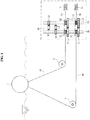
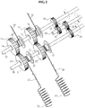
- a power converting apparatus includes a first tensile force transmitting member 40 configured to be connected to a buoyant body 1 that floats and performs a motion in the ocean and transmit a tensile force; an input shaft 10 configured to be connected to the first tensile force transmitting member 40 and perform a rotary motion by a tensile force transmitted by the first tensile force transmitting member 40; a first power transmitting member 11 configured to be coupled to the input shaft 10 through a unidirectional rotation member 14 (also designated “a first unidirectional rotation member 14") that allows only a unidirectional rotation and rotate along with the input shaft 10 or rotate while idling with respect to the input shaft 10; an energy transmitting shaft 20 configured to be provided alongside the input shaft 10 and rotate; a second power transmitting member 21 configured to be coupled to the energy transmitting shaft 20 through a medium of a unidirectional rotation member 24 (also designated "a second unidirectional rotation member 24")
- the buoyant body 1 may be a linear power source that floats on a surface of the ocean or in the ocean and generates linear motions in vertical and horizontal directions by a flux of the seawater.
- a plurality of first tensile force transmitting members 40 may be connected to the buoyant body 1 at predetermined intervals through direction changing members 2 such as, fixed pulleys, for example.
- direction changing members 2 such as, fixed pulleys, for example.
- the plurality of first tensile force transmitting members 40 connected to the buoyant body 1 may connect the buoyant body 1 to the input shaft 10 in different directions, for example, vectors.
- the plurality of first tensile force transmitting members 40 may be disposed preferably at intervals of 90 degrees.
- the first tensile force transmitting member 40 may be configured by applying a rope, a wire, or a chain that may be mechanically flexible but not stretchable, thereby transmitting a tensile force effectively.
- the input shaft 10 may be a constituent element configured to perform a rotary motion by receiving a linear power from the buoyant body 1.
- a plurality of first power transmitting members 11 may be provided on the input shaft 10 to receive power from the plurality of first tensile force transmitting members 40.
- a first drum 12 over which the first tensile force transmitting member 40 is wound or unwound may be provided to be fixed to each of the first power transmitting members 11.
- the first drum 12 may be configured to rotate along with the first power transmitting member 11.
- the first power transmitting member 11 may be coupled to the input shaft 10 through the unidirectional rotation member 14 that allows only a unidirectional rotation.
- the unidirectional rotation member 14 may be configured using a one-way clutch bearing, a ratchet gear, and the like. In the present embodiment, the unidirectional rotation member 14 may allow only a clockwise rotation. Thus, when the first tensile force transmitting member 40 is unwound from the first drum 12, the unidirectional rotation member 14 may restrict the first power transmitting member 11 and the input shaft 10, whereby the first power transmitting member 11 and the input shaft 10 may rotate together.
- the energy transmitting shaft 20 may be provided alongside the input shaft 10, and receive a power from the input shaft 10 through the second power transmitting member 21 connected to the first power transmitting member 11.
- a second drum 22 may be coupled to the second power transmitting member 21, whereby the second power transmitting member 21 and the second drum 22 may rotate together.
- a second tensile force transmitting member 50 configured to be connected to the energy storage unit and transmit a tensile force may be wound or unwound over the second drum 22.
- the second tensile force transmitting member 50 may be configured by applying a rope, a wire, or a chain that may be mechanically flexible but not stretchable, thereby transmitting a tensile force effectively.
- the second power transmitting member 21 may be connected to the energy transmitting shaft 20 through the unidirectional rotation member 24 configured using a one-way clutch bearing, a ratchet gear, and the like.
- the unidirectional rotation member 24 may be configured to have a load rotation direction identical to that of the unidirectional rotation member 14 coupled to the first power transmitting member 11.
- the unidirectional rotation member 24 may allow a clockwise rotation and allow a counterclockwise rotation.
- the unidirectional rotation member 24 may restrict the energy transmitting shaft 20 and the second power transmitting member 21, whereby the energy transmitting shaft 20 and the second power transmitting member 21 may rotate together.
- the first power transmitting member 11a and the second power transmitting member 21a may be configured using gears, however, may also be configured using various known power transmitting mechanisms such as a pulley and belt system, a sprocket and chain system, and a link mechanism, for example.
- the first power transmitting member 11 and the second power transmitting member 21 may be configured using gears having equal numbers of gear teeth. However, a gear ratio of the first power transmitting member 11 to the second power transmitting member 21 may be appropriately adjusted to transmit energy efficiently.
- the output shaft 30 may be provided alongside the input shaft 10 and the energy transmitting shaft 20 therebetween, and rotate by receiving a power alternately from the input shaft 10 and the energy transmitting shaft 20.
- the output shaft 30 may be connected directly or indirectly to a generator (not shown) configured to generate electricity.
- the first input member 13 may be fixed to the input shaft 10 and rotate along with the input shaft 10
- the second input member 23 may be fixed to the energy transmitting shaft 20 and rotate along with the energy transmitting shaft 20.
- the plurality of output members 31, for example, two output members 31 in the present embodiment, configured to be coupled to the first input member 13 and the second input member 23, respectively, and receive torques, may be coupled to the output shaft 30 through the unidirectional rotation members 32 such as, one-way clutch bearings, respectively.
- the first input member 13, the second input member 23, and the output member 31 may be configured using gears.
- the first input member 13, the second input member 23, and the output member 31 may also be configured using various known power transmitting systems such as a pulley and belt system, and a sprocket and chain system, for example.
- the unidirectional rotation members 32 coupled to the output shaft 30 may have identical load rotation directions.
- the unidirectional rotation members 32 may be configured to prevent a clockwise rotation and allow a counterclockwise rotation.
- the unidirectional rotation members 32 may also be configured to using one-way clutch bearings, ratchet gears, and the like.
- the energy storage unit may be connected to the energy transmitting shaft 20 through a medium of the second tensile force transmitting member 50 connected to the second drum 22, and configured to store energy and supply the stored energy.
- the energy storage unit may be configured using a spring 51 configured to be connected to the second tensile force transmitting member 50 and accumulate an elastic energy in response to the second tensile force transmitting member 50 being wound over the second drum 22.
- a coil spring, a flat spring, a spiral spring, and the like may be applicable as the spring 51.
- a coil spring is utilized.
- the spring 51 may accumulate an elastic force while stretching in response to the second tensile force transmitting member 50 being wound over the second drum 22, and transmit the energy by pulling the second tensile force transmitting member 50 and rotating the second drum 22 while shrinking.
- the power converting apparatus configured as described above may operate as follows.
- the buoyant body 1 moves in a predetermined direction, for example, a vertical direction or a horizontal direction, by waves, a tensile force of a rope or wire corresponding to the first tensile force transmitting member 40 may increase, and the first tensile force transmitting member 40 may be unwound from the first drum 12, which may cause a rotary motion, for example, a counterclockwise rotary motion, of the first drum 12.
- the first power transmitting member 11, for example, a gear in the present embodiment, provided as an integral body with the first drum 12 may rotate counterclockwise at an angular velocity equal to that of the first drum 12.
- the unidirectional rotation member 14 disposed between the first power transmitting member 11 and the input shaft 10 may restrict a counterclockwise motion and thus, the first power transmitting member 11 and the input shaft 10 may rotate together.
- a portion of a torque of the first power transmitting member 11 may be used to rotate the input shaft 10, and a remaining portion of the torque may be used to relatively rotate the second power transmitting member 21 connected to the first power transmitting member 11, and the second drum 22 with respect to the energy transmitting shaft 20 so that the second tensile force transmitting member 50 may be wound over the second drum 22, whereby the spring 51 of the energy storage unit may stretch to store an elastic energy.
- a torque of the input shaft 10 may be transmitted to the output shaft 30 through the first input member 13 and the output member 31 connected to the first input member 13, whereby the output shaft 30 may rotate in one direction, for example, clockwise in the present embodiment.
- the elastic energy stored in the spring 51 of the energy storage unit may be converted into a tensile force of the second tensile force transmitting member 50 and thus, the second drum 22 and the second power transmitting member 21 provided as an integral body with the second drum 22 may perform counterclockwise rotary motions.
- the energy received from the spring 51 may be used as a rotation power of the energy transmitting shaft 20 connected through the unidirectional rotation member 24.
- a counterclockwise torque of the energy transmitting shaft 20 may be transmitted to the output shaft 30 through the second input member 23 and the output member 31 connected to the second input member 23, and used to rotate the output shaft 30.
- the first power transmitting member 11 When the elastic energy is transmitted from the spring 51 to the second power transmitting member 21 and the second power transmitting member 21 rotates counterclockwise, the first power transmitting member 11 may rotate clockwise. Since the unidirectional rotation member 14 connected to an inner side of the first power transmitting member 11 allows a clockwise rotation, a torque of the second power transmitting member 21 may not be transmitted to the input shaft 10, and the first power transmitting member 11 and the first drum 12 may wind the first tensile force transmitting member 40 while idling with respect to the input shaft 10.
- a tensile force is applied to one of the plurality of first tensile force transmitting members 40 by a motion of the buoyant body 1, and the first drum 12 and the first power transmitting member 11 rotate, a portion of a power transmitted by the first tensile force transmitting member 40 may be converted to a torque of the input shaft 10, and a remaining portion of the power may be transmitted to the energy storage unit through the second power transmitting member 21 and the second tensile force transmitting member 50 and accumulated as an elastic energy.
- the elastic energy accumulated in the energy storage unit may be transmitted to the output shaft 30 through the energy transmitting shaft 20, whereby the output shaft 30 may rotate.
- the output shaft 30 may continuously perform rotary motions while receiving a power alternately from the input shaft 10 and the energy transmitting shaft 20, whereby a generation efficiency may significantly increase.
- the plurality of first tensile force transmitting members 40 may be connected to the buoyant body 1, and the plurality of first power transmitting members 11 and the plurality of first drums 12 separately connected to the first tensile force transmitting members 40, respectively, may be provided on the input shaft 10.
- the plurality of second power transmitting members 21 connected to the plurality of first power transmitting members 11 may be provided on the energy transmitting shaft 20, the second drums 22 may be fixed to the second power transmitting members 21, respectively, and the plurality of second drums 22 may be configured to be connected to the plurality of energy storage members 51 through the plurality of second tensile force transmitting members 50.
- a single first tensile force transmitting member 40, a single first power transmitting member 11, a single first drum 12, a single second power transmitting member 21, and a single second drum 22 may be configured.
- the energy storage unit corresponding to the spring 51 configured to store an elastic energy
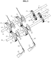
- the energy storage unit may be configured using a weight configured to be connected to the second tensile force transmitting member 50 and store a potential energy.
- the energy storage unit may be configured using a weight 52 that is connected to the second tensile force transmitting member 50 and accumulates a potential energy while moving upward in response to the second tensile force transmitting member 50 being wound over the second drum 22.
- the weight 52 may fall downward, thereby rotating the second drum 22, rotating the energy transmitting shaft 20, and rotating the output shaft 30.
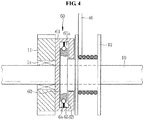
- a decoupler 60 may be configured between the first power transmitting member 11 and the first drum 12 receiving a linear power from the buoyant body 1.
- the decoupler 60 may block a power transmission from the first drum 12 to the first power transmitting member 11, whereby the entire configuration of the power transmitting apparatus may be protected.
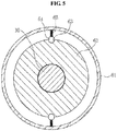
- the decoupler 60 shown in FIGS. 4 and 5 includes a housing 61 configured to be fixed to the first power transmitting member 11 and in which a receiving space 61a is provided, a coupling disk 62 configured to be fixed to one side surface of the first drum 12, inserted into an internal portion of the housing 61, and in which a fixing groove 63 is provided to be concave on an outer circumferential surface thereof, a ball 64 provided in the internal portion of the housing 61, and configured to be inserted into the fixing groove 63, and a spring 65 provided in the internal portion of the housing 61, and configured to elastically pressurize the ball 64 toward the coupling disk 62.
- the ball 64 may be typically elastically inserted into the fixing groove 63 of the coupling disk 62, a coupling state between the coupling disk 62 and the housing 61 may be maintained, and the first drum 12 may be fixed to the first power transmitting member 11.
- the ball 64 may be separated from the fixing groove 63 of the coupling disk 62, the coupling state between the coupling disk 62 and the housing 61 may be cancelled, and the coupling disk 62 may idle on an inner side of the housing 61, whereby the power transmission may be blocked.
- the first power transmitting member 11 may be coupled to the input shaft 10 through the unidirectional rotation member 14 that allows only a unidirectional rotation.
- the first power transmitting member 11 may be coupled to the input shaft 10 by a known decoupler that prevents a power transmission from the first power transmitting member 11 to the input shaft 10 when a tensile force greater than or equal to a set value is applied from the first tensile force transmitting member 40, in turn preventing damage to constituent elements to be caused by an excessive load.
- a single input shaft 10, a single energy transmitting shaft 20, and a single output shaft 30 are configured, and the output shaft 30 may receive power from the single input shaft 10 and the single energy transmitting shaft 20.
- a plurality of input shafts 10 and a plurality of energy transmitting shafts 20 may be configured, a single output shaft 30 may be configured, and the single output shaft 30 may receive power from the plurality of input shafts 10 and the plurality of energy transmitting shafts 20 and rotate, thereby performing a wave power generation.
- the output shaft 30 may have a uniform rotation velocity.
- a number of rotations of a generator connected to the output shaft 30 may be maintained to be uniform, and stable generation of electricity may be achieved.
- the present application may be applicable to an apparatus that may generate a rotation power from a linear power source that generates a linear power, for example, a wave power generation apparatus.
Landscapes
- Engineering & Computer Science (AREA)
- General Engineering & Computer Science (AREA)
- Mechanical Engineering (AREA)
- Chemical & Material Sciences (AREA)
- Combustion & Propulsion (AREA)
- Other Liquid Machine Or Engine Such As Wave Power Use (AREA)
- Transmission Devices (AREA)
- Devices For Conveying Motion By Means Of Endless Flexible Members (AREA)
Priority Applications (1)
| Application Number | Priority Date | Filing Date | Title |
|---|---|---|---|
| EP16163818.4A EP3112666A1 (en) | 2013-07-31 | 2014-04-21 | Power conversion device |
Applications Claiming Priority (3)
| Application Number | Priority Date | Filing Date | Title |
|---|---|---|---|
| KR1020130091243A KR101389488B1 (ko) | 2013-07-31 | 2013-07-31 | 동력변환장치 |
| KR1020140046679A KR101602901B1 (ko) | 2014-04-18 | 2014-04-18 | 파력발전용 동력변환장치 |
| PCT/KR2014/003465 WO2015016457A1 (ko) | 2013-07-31 | 2014-04-21 | 동력변환장치 |
Related Child Applications (2)
| Application Number | Title | Priority Date | Filing Date |
|---|---|---|---|
| EP16163818.4A Division EP3112666A1 (en) | 2013-07-31 | 2014-04-21 | Power conversion device |
| EP16163818.4A Division-Into EP3112666A1 (en) | 2013-07-31 | 2014-04-21 | Power conversion device |
Publications (3)
| Publication Number | Publication Date |
|---|---|
| EP2860423A1 EP2860423A1 (en) | 2015-04-15 |
| EP2860423A4 EP2860423A4 (en) | 2016-04-06 |
| EP2860423B1 true EP2860423B1 (en) | 2018-03-28 |
Family
ID=52431954
Family Applications (2)
| Application Number | Title | Priority Date | Filing Date |
|---|---|---|---|
| EP14815209.3A Active EP2860423B1 (en) | 2013-07-31 | 2014-04-21 | Power conversion device |
| EP16163818.4A Withdrawn EP3112666A1 (en) | 2013-07-31 | 2014-04-21 | Power conversion device |
Family Applications After (1)
| Application Number | Title | Priority Date | Filing Date |
|---|---|---|---|
| EP16163818.4A Withdrawn EP3112666A1 (en) | 2013-07-31 | 2014-04-21 | Power conversion device |
Country Status (17)
| Country | Link |
|---|---|
| US (1) | US9995269B2 (ja) |
| EP (2) | EP2860423B1 (ja) |
| JP (2) | JP6346271B2 (ja) |
| CN (2) | CN105864379B (ja) |
| AU (1) | AU2014297162B2 (ja) |
| BR (1) | BR112016001862B1 (ja) |
| CA (1) | CA2918495C (ja) |
| CL (1) | CL2016000245A1 (ja) |
| EC (1) | ECSMU16004357U (ja) |
| ES (1) | ES2671820T3 (ja) |
| MX (1) | MX368752B (ja) |
| NO (1) | NO2860423T3 (ja) |
| PE (1) | PE20160349A1 (ja) |
| PH (1) | PH12016500205B1 (ja) |
| PT (1) | PT2860423T (ja) |
| RU (1) | RU2631349C2 (ja) |
| WO (1) | WO2015016457A1 (ja) |
Families Citing this family (35)
| Publication number | Priority date | Publication date | Assignee | Title |
|---|---|---|---|---|
| US10280894B1 (en) * | 2014-11-17 | 2019-05-07 | Andrew L. Bender | Wave powered electric generator device, system and method |
| WO2017025544A1 (en) * | 2015-08-12 | 2017-02-16 | Jospa Limited | A wave energy convertor |
| KR20150143381A (ko) * | 2015-10-13 | 2015-12-23 | 정민시 | 중력체에 의한 부력 발전장치 |
| KR101646162B1 (ko) * | 2015-11-16 | 2016-08-05 | 정민시 | 중력과 부력을 이용한 자가 발전장치 및 이를 이용한 해양 경계등 |
| RU2629584C2 (ru) * | 2016-01-11 | 2017-08-30 | Виктор Иванович Волкович | Механизм преобразования возвратно-поступательного движения в непрерывное вращательное |
| CA3011357A1 (en) * | 2016-01-13 | 2017-07-20 | Ingine, Inc. | Wave power generation device including wire |
| ES2629761B1 (es) * | 2016-02-11 | 2018-05-30 | Smalle Technologies, S.L. | Dispositivo para transformar energía del oleaje en energía eléctrica |
| ES2630735B1 (es) * | 2016-02-19 | 2018-02-16 | Pablo TORRES BLANCO | Módulo convertidor de energía undimotriz, de flotabilidad desacoplable. |
| PL232262B1 (pl) * | 2016-03-14 | 2019-05-31 | Gawel Grzegorz | Przetwornik drgań na energię elektryczną |
| KR101758657B1 (ko) * | 2016-03-25 | 2017-07-17 | 성용준 | 1축 동력 변환 장치 |
| ES2638838B2 (es) * | 2016-04-22 | 2018-01-23 | Universidade Da Coruña | Subsistema de conversión primaria de convertidor undimotriz con acumulador de doble giro con resortes helicoidales de tracción. |
| ES2639048B1 (es) * | 2016-04-25 | 2018-08-09 | Universidade Da Coruña | Acumulador mecánico rotativo, de doble giro, con resortes de tracción |
| JP6134425B1 (ja) * | 2016-06-27 | 2017-05-24 | 株式会社内藤ハウス | 駆動装置 |
| CN107559132B (zh) * | 2016-07-03 | 2023-05-09 | 曲言明 | 浮体绳轮波浪能采集系统 |
| CN106121917B (zh) * | 2016-08-30 | 2018-07-27 | 山东省科学院海洋仪器仪表研究所 | 用于海上多能发电装置的机械能聚能机构 |
| CN106763607B (zh) * | 2016-12-21 | 2019-08-13 | 梁渤涛 | 蓄存和释放机械能的机构 |
| KR101918842B1 (ko) * | 2017-03-31 | 2019-02-08 | 주식회사 인진 | 파력 발전 설비 제어 시스템 및 방법 |
| CN106870266B (zh) * | 2017-04-13 | 2018-08-03 | 江苏科技大学 | 一种用于水下的直线差速发电装置 |
| RU2652763C2 (ru) * | 2017-05-03 | 2018-04-28 | Павел Григорьевич Петрик | Устройство для преобразования однонаправленного прерывистого движения во вращательное |
| GB2565333A (en) * | 2017-08-10 | 2019-02-13 | Marine Power Systems Ltd | Drive assembly |
| RU2661259C1 (ru) * | 2017-11-27 | 2018-07-13 | Артем Владимирович Сокол | Устройство для передачи вращательного движения от двух или большего числа приводов |
| RU2708403C2 (ru) * | 2017-12-12 | 2019-12-06 | Акционерное общество "Информационные спутниковые системы" имени академика М.Ф. Решетнёва" | Механизм передачи движения |
| KR102027552B1 (ko) * | 2018-03-09 | 2019-10-01 | 주식회사 인진 | 파력발전 시스템 및 그 제어 방법 |
| WO2019210795A1 (zh) * | 2018-05-02 | 2019-11-07 | Liu Gang | 独立潮汐发电机组 |
| ES2732238A1 (es) * | 2018-05-21 | 2019-11-21 | Blanco Pablo Torres | Módulo convertidor de energía undimotriz |
| CN109027165B (zh) * | 2018-09-05 | 2019-12-27 | 南京航空航天大学 | 一种弹簧缓冲式双向摆动变单向转动增速装置 |
| CN110340878A (zh) * | 2019-07-24 | 2019-10-18 | 东南大学 | 一种分布式有源无源混合绳索驱动系统 |
| CN111255614B (zh) * | 2020-03-16 | 2021-05-04 | 台州路桥布鲁新能源有限公司 | 一种利用海浪进行发电的装置 |
| US11649801B2 (en) * | 2020-08-14 | 2023-05-16 | Narayan R Iyer | System and method of capturing and linearizing oceanic wave motion using a buoy flotation device and an alternating-to-direct motion converter |
| US11746860B2 (en) * | 2020-12-23 | 2023-09-05 | Liftwave, Inc. | Self-reeling belt drive |
| RU206076U1 (ru) * | 2021-05-04 | 2021-08-19 | Федеральное государственное бюджетное образовательное учреждение высшего образования "Кубанский государственный технологический университет" (ФГБОУ ВО "КубГТУ") | Рекуператор транспортного средства с упругими элементами |
| KR102325566B1 (ko) * | 2021-09-14 | 2021-11-15 | 우광산업(주) | 변위증가시스템 및 이를 이용한 계류장치 |
| CN114476994B (zh) * | 2021-12-28 | 2024-06-18 | 中国特种飞行器研究所 | 一种新型海上自主收放绞车系统 |
| US11661916B1 (en) * | 2022-01-10 | 2023-05-30 | LDI Consulting Inc. | Wave energy harnessing devices |
| CN116498670B (zh) * | 2023-05-22 | 2024-01-26 | 广州海洋地质调查局 | 一种海洋波浪能发电的单向传动结构 |
Family Cites Families (38)
| Publication number | Priority date | Publication date | Assignee | Title |
|---|---|---|---|---|
| US332875A (en) | 1885-12-22 | Tidal power | ||
| US755799A (en) * | 1902-02-19 | 1904-03-29 | Max L Schlueter | Power-transmitting apparatus. |
| US3297300A (en) * | 1964-09-30 | 1967-01-10 | Demetrios K Mountanos | Apparatus for deriving useful energy from sea waves |
| JPS5282633U (ja) * | 1975-12-17 | 1977-06-20 | ||
| JPS5282633A (en) | 1975-12-29 | 1977-07-11 | Kubota Ltd | Mould supporting apparatus of centrifugal casting machine |
| FR2339071A1 (fr) | 1976-01-20 | 1977-08-19 | Comte Cyrille | Appareillage d'exploitation de l'energie des vagues |
| US4170738A (en) * | 1977-12-19 | 1979-10-09 | Q Corporation | Energy device powered by the motion of water beneath waves |
| JPS581273B2 (ja) | 1978-09-14 | 1983-01-10 | 伊原 松太郎 | 波浪エネルギ−変換装置 |
| US4228360A (en) * | 1979-06-08 | 1980-10-14 | Pablo Navarro | Wave motion apparatus |
| US5424582A (en) | 1984-05-24 | 1995-06-13 | Elektra Power Industries, Inc. | Cushioned dual-action constant speed wave power generator |
| US4754157A (en) * | 1985-10-01 | 1988-06-28 | Windle Tom J | Float type wave energy extraction apparatus and method |
| JPS6318188A (ja) | 1986-07-07 | 1988-01-26 | マイクル・ダニヘル | 波動エネルギを機械運動に変換する装置 |
| JP3249550B2 (ja) | 1991-07-31 | 2002-01-21 | エイ・テイ・シイ株式会社 | ばね押圧ボール型ハウジングユニット |
| EP1466090B1 (en) | 2002-01-08 | 2007-03-14 | Seabased AB | Wave-power unit and plant for the production of electric power and a method of generating electric power |
| KR100537464B1 (ko) | 2002-11-13 | 2005-12-19 | 채찬복 | 파도를 이용한 발전장치 |
| DE10322230A1 (de) | 2003-05-17 | 2004-12-02 | Ina-Schaeffler Kg | Vorrichtung für Zusatzaggregate einer Brennkraftmaschine |
| ES2238167B1 (es) * | 2003-11-28 | 2007-12-16 | Arlas Invest, S.L. | Sistema de generacion de energia a partir de la olas del mar. |
| JP2006022873A (ja) | 2004-07-07 | 2006-01-26 | Ntn Corp | 回転伝達装置 |
| JP2006189018A (ja) * | 2005-01-05 | 2006-07-20 | Shozo Nanba | 波エネルギー変換装置 |
| JP2008180086A (ja) * | 2005-03-31 | 2008-08-07 | Yamaguchi Univ | 波力エネルギー変換装置 |
| JPWO2008038825A1 (ja) * | 2006-09-27 | 2010-07-15 | 巖 池上 | 波浪エネルギ貯留装置およびそれを用いた発電装置 |
| NO325878B1 (no) * | 2007-04-17 | 2008-08-11 | Straumekraft As | Anordning ved bolgekraftverk |
| US20080272600A1 (en) * | 2007-05-02 | 2008-11-06 | Chris Olson | Lever operated pivoting float with generator |
| WO2009046507A1 (en) * | 2007-10-10 | 2009-04-16 | Atanas Atanasov | Wave power station |
| US7891183B2 (en) * | 2008-02-11 | 2011-02-22 | King Fahd University Of Petroleum And Minerals | Wave-based power generation system |
| JP5604310B2 (ja) * | 2008-02-20 | 2014-10-08 | オーシャン・ハーベスティング・テクノロジーズ・エイビイ | 波力エネルギープラント |
| US20090212562A1 (en) * | 2008-02-27 | 2009-08-27 | The Boeing Company | Method and apparatus for tidal power generation |
| AU2008365098B2 (en) | 2008-12-10 | 2013-09-19 | Mile Dragic | System for conversion of aquatic wave energy into electrical energy |
| US20110031750A1 (en) | 2009-08-06 | 2011-02-10 | Peter Alfred Kreissig | Wave powered electricity generation |
| IT1395325B1 (it) * | 2009-08-25 | 2012-09-14 | A P Sistem Di Piccinini Alberto | Sistema per una produzione di energia elettrica o meccanica dal moto ondoso |
| CN101997398A (zh) | 2009-08-27 | 2011-03-30 | 刘世珍 | 动力产生系统及装置 |
| WO2011126451A1 (en) | 2010-04-07 | 2011-10-13 | Ocean Harvesting Technologies Ab | Wave energy converter and transmission |
| RU2447317C2 (ru) | 2010-04-20 | 2012-04-10 | Федеральное государственное образовательное учреждение высшего профессионального образования Военная академия Ракетных войск стратегического назначения имени Петра Великого МО РФ | Устройство получения электроэнергии за счет колебаний водной поверхности |
| AU2011318469A1 (en) * | 2010-10-21 | 2013-06-06 | Arthur Robert Williams | Full-water-column surge-type wave-energy converter |
| DE102011008877A1 (de) * | 2011-01-18 | 2012-07-19 | Jan Peter Peckolt | System und Verfahren zur Energieauskopplung aus Meereswellen |
| WO2012115456A2 (ko) | 2011-02-23 | 2012-08-30 | Lee Dong In | 파력 발전 장치 |
| KR101049518B1 (ko) | 2011-03-22 | 2011-07-15 | 이동인 | 파력 발전 장치 |
| CN104981606B (zh) | 2012-10-05 | 2017-12-08 | 海洋采伐科技有限公司 | 波能转换器 |
-
2014
- 2014-04-21 EP EP14815209.3A patent/EP2860423B1/en active Active
- 2014-04-21 CN CN201610225295.1A patent/CN105864379B/zh active Active
- 2014-04-21 PE PE2016000200A patent/PE20160349A1/es unknown
- 2014-04-21 PT PT148152093T patent/PT2860423T/pt unknown
- 2014-04-21 US US14/413,408 patent/US9995269B2/en active Active
- 2014-04-21 JP JP2016518257A patent/JP6346271B2/ja active Active
- 2014-04-21 CA CA2918495A patent/CA2918495C/en active Active
- 2014-04-21 EP EP16163818.4A patent/EP3112666A1/en not_active Withdrawn
- 2014-04-21 WO PCT/KR2014/003465 patent/WO2015016457A1/ko active Application Filing
- 2014-04-21 NO NO14815209A patent/NO2860423T3/no unknown
- 2014-04-21 RU RU2016106584A patent/RU2631349C2/ru active
- 2014-04-21 CN CN201480042787.6A patent/CN105408662B/zh active Active
- 2014-04-21 MX MX2016000959A patent/MX368752B/es active IP Right Grant
- 2014-04-21 BR BR112016001862-1A patent/BR112016001862B1/pt active IP Right Grant
- 2014-04-21 ES ES14815209.3T patent/ES2671820T3/es active Active
- 2014-04-21 AU AU2014297162A patent/AU2014297162B2/en active Active
-
2016
- 2016-01-29 CL CL2016000245A patent/CL2016000245A1/es unknown
- 2016-01-29 PH PH12016500205A patent/PH12016500205B1/en unknown
- 2016-01-29 EC ECIEPI20164357U patent/ECSMU16004357U/es unknown
- 2016-04-11 JP JP2016078767A patent/JP6210245B2/ja active Active
Non-Patent Citations (1)
| Title |
|---|
| None * |
Also Published As
| Publication number | Publication date |
|---|---|
| WO2015016457A1 (ko) | 2015-02-05 |
| JP2016182951A (ja) | 2016-10-20 |
| PE20160349A1 (es) | 2016-04-27 |
| MX368752B (es) | 2019-10-15 |
| US20150275847A1 (en) | 2015-10-01 |
| CA2918495A1 (en) | 2015-02-05 |
| CL2016000245A1 (es) | 2016-10-07 |
| AU2014297162B2 (en) | 2017-08-03 |
| US9995269B2 (en) | 2018-06-12 |
| ECSMU16004357U (es) | 2017-03-31 |
| EP3112666A1 (en) | 2017-01-04 |
| JP2016521819A (ja) | 2016-07-25 |
| JP6210245B2 (ja) | 2017-10-11 |
| NO2860423T3 (ja) | 2018-08-25 |
| RU2016106584A (ru) | 2017-08-30 |
| PT2860423T (pt) | 2018-06-06 |
| AU2014297162A1 (en) | 2016-02-11 |
| EP2860423A4 (en) | 2016-04-06 |
| JP6346271B2 (ja) | 2018-06-20 |
| BR112016001862B1 (pt) | 2022-07-19 |
| CA2918495C (en) | 2018-12-11 |
| CN105864379B (zh) | 2019-10-01 |
| CN105408662B (zh) | 2018-06-15 |
| EP2860423A1 (en) | 2015-04-15 |
| BR112016001862A2 (pt) | 2017-08-01 |
| ES2671820T3 (es) | 2018-06-08 |
| RU2631349C2 (ru) | 2017-09-21 |
| PH12016500205A1 (en) | 2016-04-25 |
| PH12016500205B1 (en) | 2016-04-25 |
| MX2016000959A (es) | 2016-08-11 |
| CN105864379A (zh) | 2016-08-17 |
| CN105408662A (zh) | 2016-03-16 |
Similar Documents
| Publication | Publication Date | Title |
|---|---|---|
| EP2860423B1 (en) | Power conversion device | |
| KR101751218B1 (ko) | 파력발전용 동력변환장치 | |
| KR101602901B1 (ko) | 파력발전용 동력변환장치 | |
| US7315092B2 (en) | Wave powered electric generating device | |
| US8698337B2 (en) | Matrix sea wave power generating device | |
| KR101769761B1 (ko) | 와이어를 포함하는 파력 발전 장치 | |
| GB2479348A (en) | Wave power converter with one way clutch | |
| US20160215751A1 (en) | Power converting apparatus | |
| US20170201155A1 (en) | Electric power generation system and reciprocating mechanism for electric power generation system | |
| JP2009221999A (ja) | 波力発電装置 | |
| JP6734930B2 (ja) | 1軸動力変換装置 | |
| KR101389488B1 (ko) | 동력변환장치 | |
| US20180171963A1 (en) | Pendulum electricity-generating device using natural energy | |
| OA17823A (en) | Power conversion device | |
| WO2022214912A1 (en) | Electricity generating device | |
| US8395271B2 (en) | Pass-through PTO mechanism for renewable energy systems | |
| WO2017138280A1 (ja) | 発電システム及び発電システム用弾性エネルギー蓄積装置 | |
| KR20120035710A (ko) | 파력 발전 장치 |
Legal Events
| Date | Code | Title | Description |
|---|---|---|---|
| PUAI | Public reference made under article 153(3) epc to a published international application that has entered the european phase |
Free format text: ORIGINAL CODE: 0009012 |
|
| 17P | Request for examination filed |
Effective date: 20150107 |
|
| AK | Designated contracting states |
Kind code of ref document: A1 Designated state(s): AL AT BE BG CH CY CZ DE DK EE ES FI FR GB GR HR HU IE IS IT LI LT LU LV MC MK MT NL NO PL PT RO RS SE SI SK SM TR |
|
| AX | Request for extension of the european patent |
Extension state: BA ME |
|
| REG | Reference to a national code |
Ref country code: DE Ref legal event code: R079 Ref document number: 602014023102 Country of ref document: DE Free format text: PREVIOUS MAIN CLASS: F16H0007040000 Ipc: F03B0013180000 |
|
| RA4 | Supplementary search report drawn up and despatched (corrected) |
Effective date: 20160308 |
|
| RIC1 | Information provided on ipc code assigned before grant |
Ipc: F16D 43/208 20060101ALI20160302BHEP Ipc: F03B 13/18 20060101AFI20160302BHEP Ipc: F16H 33/02 20060101ALI20160302BHEP Ipc: F16H 19/06 20060101ALI20160302BHEP Ipc: F16H 31/00 20060101ALI20160302BHEP |
|
| DAX | Request for extension of the european patent (deleted) | ||
| GRAP | Despatch of communication of intention to grant a patent |
Free format text: ORIGINAL CODE: EPIDOSNIGR1 |
|
| INTG | Intention to grant announced |
Effective date: 20171020 |
|
| GRAS | Grant fee paid |
Free format text: ORIGINAL CODE: EPIDOSNIGR3 |
|
| GRAA | (expected) grant |
Free format text: ORIGINAL CODE: 0009210 |
|
| AK | Designated contracting states |
Kind code of ref document: B1 Designated state(s): AL AT BE BG CH CY CZ DE DK EE ES FI FR GB GR HR HU IE IS IT LI LT LU LV MC MK MT NL NO PL PT RO RS SE SI SK SM TR |
|
| REG | Reference to a national code |
Ref country code: GB Ref legal event code: FG4D |
|
| REG | Reference to a national code |
Ref country code: CH Ref legal event code: EP |
|
| REG | Reference to a national code |
Ref country code: FR Ref legal event code: PLFP Year of fee payment: 5 |
|
| REG | Reference to a national code |
Ref country code: AT Ref legal event code: REF Ref document number: 983683 Country of ref document: AT Kind code of ref document: T Effective date: 20180415 |
|
| REG | Reference to a national code |
Ref country code: IE Ref legal event code: FG4D |
|
| REG | Reference to a national code |
Ref country code: DE Ref legal event code: R096 Ref document number: 602014023102 Country of ref document: DE |
|
| REG | Reference to a national code |
Ref country code: PT Ref legal event code: SC4A Ref document number: 2860423 Country of ref document: PT Date of ref document: 20180606 Kind code of ref document: T Free format text: AVAILABILITY OF NATIONAL TRANSLATION Effective date: 20180530 |
|
| REG | Reference to a national code |
Ref country code: ES Ref legal event code: FG2A Ref document number: 2671820 Country of ref document: ES Kind code of ref document: T3 Effective date: 20180608 |
|
| REG | Reference to a national code |
Ref country code: NO Ref legal event code: T2 Effective date: 20180328 |
|
| PG25 | Lapsed in a contracting state [announced via postgrant information from national office to epo] |
Ref country code: LT Free format text: LAPSE BECAUSE OF FAILURE TO SUBMIT A TRANSLATION OF THE DESCRIPTION OR TO PAY THE FEE WITHIN THE PRESCRIBED TIME-LIMIT Effective date: 20180328 Ref country code: HR Free format text: LAPSE BECAUSE OF FAILURE TO SUBMIT A TRANSLATION OF THE DESCRIPTION OR TO PAY THE FEE WITHIN THE PRESCRIBED TIME-LIMIT Effective date: 20180328 Ref country code: FI Free format text: LAPSE BECAUSE OF FAILURE TO SUBMIT A TRANSLATION OF THE DESCRIPTION OR TO PAY THE FEE WITHIN THE PRESCRIBED TIME-LIMIT Effective date: 20180328 |
|
| REG | Reference to a national code |
Ref country code: NL Ref legal event code: MP Effective date: 20180328 |
|
| REG | Reference to a national code |
Ref country code: LT Ref legal event code: MG4D |
|
| REG | Reference to a national code |
Ref country code: DE Ref legal event code: R082 Ref document number: 602014023102 Country of ref document: DE Representative=s name: HOEFER & PARTNER PATENTANWAELTE MBB, DE |
|
| PG25 | Lapsed in a contracting state [announced via postgrant information from national office to epo] |
Ref country code: GR Free format text: LAPSE BECAUSE OF FAILURE TO SUBMIT A TRANSLATION OF THE DESCRIPTION OR TO PAY THE FEE WITHIN THE PRESCRIBED TIME-LIMIT Effective date: 20180629 Ref country code: BG Free format text: LAPSE BECAUSE OF FAILURE TO SUBMIT A TRANSLATION OF THE DESCRIPTION OR TO PAY THE FEE WITHIN THE PRESCRIBED TIME-LIMIT Effective date: 20180628 Ref country code: RS Free format text: LAPSE BECAUSE OF FAILURE TO SUBMIT A TRANSLATION OF THE DESCRIPTION OR TO PAY THE FEE WITHIN THE PRESCRIBED TIME-LIMIT Effective date: 20180328 Ref country code: SE Free format text: LAPSE BECAUSE OF FAILURE TO SUBMIT A TRANSLATION OF THE DESCRIPTION OR TO PAY THE FEE WITHIN THE PRESCRIBED TIME-LIMIT Effective date: 20180328 Ref country code: LV Free format text: LAPSE BECAUSE OF FAILURE TO SUBMIT A TRANSLATION OF THE DESCRIPTION OR TO PAY THE FEE WITHIN THE PRESCRIBED TIME-LIMIT Effective date: 20180328 |
|
| PG25 | Lapsed in a contracting state [announced via postgrant information from national office to epo] |
Ref country code: NL Free format text: LAPSE BECAUSE OF FAILURE TO SUBMIT A TRANSLATION OF THE DESCRIPTION OR TO PAY THE FEE WITHIN THE PRESCRIBED TIME-LIMIT Effective date: 20180328 Ref country code: AL Free format text: LAPSE BECAUSE OF FAILURE TO SUBMIT A TRANSLATION OF THE DESCRIPTION OR TO PAY THE FEE WITHIN THE PRESCRIBED TIME-LIMIT Effective date: 20180328 Ref country code: PL Free format text: LAPSE BECAUSE OF FAILURE TO SUBMIT A TRANSLATION OF THE DESCRIPTION OR TO PAY THE FEE WITHIN THE PRESCRIBED TIME-LIMIT Effective date: 20180328 Ref country code: RO Free format text: LAPSE BECAUSE OF FAILURE TO SUBMIT A TRANSLATION OF THE DESCRIPTION OR TO PAY THE FEE WITHIN THE PRESCRIBED TIME-LIMIT Effective date: 20180328 Ref country code: IT Free format text: LAPSE BECAUSE OF FAILURE TO SUBMIT A TRANSLATION OF THE DESCRIPTION OR TO PAY THE FEE WITHIN THE PRESCRIBED TIME-LIMIT Effective date: 20180328 Ref country code: EE Free format text: LAPSE BECAUSE OF FAILURE TO SUBMIT A TRANSLATION OF THE DESCRIPTION OR TO PAY THE FEE WITHIN THE PRESCRIBED TIME-LIMIT Effective date: 20180328 |
|
| PG25 | Lapsed in a contracting state [announced via postgrant information from national office to epo] |
Ref country code: CZ Free format text: LAPSE BECAUSE OF FAILURE TO SUBMIT A TRANSLATION OF THE DESCRIPTION OR TO PAY THE FEE WITHIN THE PRESCRIBED TIME-LIMIT Effective date: 20180328 Ref country code: SM Free format text: LAPSE BECAUSE OF FAILURE TO SUBMIT A TRANSLATION OF THE DESCRIPTION OR TO PAY THE FEE WITHIN THE PRESCRIBED TIME-LIMIT Effective date: 20180328 Ref country code: SK Free format text: LAPSE BECAUSE OF FAILURE TO SUBMIT A TRANSLATION OF THE DESCRIPTION OR TO PAY THE FEE WITHIN THE PRESCRIBED TIME-LIMIT Effective date: 20180328 |
|
| REG | Reference to a national code |
Ref country code: CH Ref legal event code: PL |
|
| REG | Reference to a national code |
Ref country code: AT Ref legal event code: MK05 Ref document number: 983683 Country of ref document: AT Kind code of ref document: T Effective date: 20180328 |
|
| REG | Reference to a national code |
Ref country code: BE Ref legal event code: MM Effective date: 20180430 |
|
| REG | Reference to a national code |
Ref country code: DE Ref legal event code: R097 Ref document number: 602014023102 Country of ref document: DE |
|
| PG25 | Lapsed in a contracting state [announced via postgrant information from national office to epo] |
Ref country code: MC Free format text: LAPSE BECAUSE OF FAILURE TO SUBMIT A TRANSLATION OF THE DESCRIPTION OR TO PAY THE FEE WITHIN THE PRESCRIBED TIME-LIMIT Effective date: 20180328 Ref country code: LU Free format text: LAPSE BECAUSE OF NON-PAYMENT OF DUE FEES Effective date: 20180421 Ref country code: AT Free format text: LAPSE BECAUSE OF FAILURE TO SUBMIT A TRANSLATION OF THE DESCRIPTION OR TO PAY THE FEE WITHIN THE PRESCRIBED TIME-LIMIT Effective date: 20180328 Ref country code: DK Free format text: LAPSE BECAUSE OF FAILURE TO SUBMIT A TRANSLATION OF THE DESCRIPTION OR TO PAY THE FEE WITHIN THE PRESCRIBED TIME-LIMIT Effective date: 20180328 |
|
| PLBE | No opposition filed within time limit |
Free format text: ORIGINAL CODE: 0009261 |
|
| STAA | Information on the status of an ep patent application or granted ep patent |
Free format text: STATUS: NO OPPOSITION FILED WITHIN TIME LIMIT |
|
| PG25 | Lapsed in a contracting state [announced via postgrant information from national office to epo] |
Ref country code: LI Free format text: LAPSE BECAUSE OF NON-PAYMENT OF DUE FEES Effective date: 20180430 Ref country code: CH Free format text: LAPSE BECAUSE OF NON-PAYMENT OF DUE FEES Effective date: 20180430 Ref country code: BE Free format text: LAPSE BECAUSE OF NON-PAYMENT OF DUE FEES Effective date: 20180430 |
|
| 26N | No opposition filed |
Effective date: 20190103 |
|
| PG25 | Lapsed in a contracting state [announced via postgrant information from national office to epo] |
Ref country code: SI Free format text: LAPSE BECAUSE OF FAILURE TO SUBMIT A TRANSLATION OF THE DESCRIPTION OR TO PAY THE FEE WITHIN THE PRESCRIBED TIME-LIMIT Effective date: 20180328 |
|
| PG25 | Lapsed in a contracting state [announced via postgrant information from national office to epo] |
Ref country code: MT Free format text: LAPSE BECAUSE OF NON-PAYMENT OF DUE FEES Effective date: 20180421 |
|
| PG25 | Lapsed in a contracting state [announced via postgrant information from national office to epo] |
Ref country code: TR Free format text: LAPSE BECAUSE OF FAILURE TO SUBMIT A TRANSLATION OF THE DESCRIPTION OR TO PAY THE FEE WITHIN THE PRESCRIBED TIME-LIMIT Effective date: 20180328 |
|
| PG25 | Lapsed in a contracting state [announced via postgrant information from national office to epo] |
Ref country code: CY Free format text: LAPSE BECAUSE OF FAILURE TO SUBMIT A TRANSLATION OF THE DESCRIPTION OR TO PAY THE FEE WITHIN THE PRESCRIBED TIME-LIMIT Effective date: 20180328 Ref country code: HU Free format text: LAPSE BECAUSE OF FAILURE TO SUBMIT A TRANSLATION OF THE DESCRIPTION OR TO PAY THE FEE WITHIN THE PRESCRIBED TIME-LIMIT; INVALID AB INITIO Effective date: 20140421 Ref country code: MK Free format text: LAPSE BECAUSE OF NON-PAYMENT OF DUE FEES Effective date: 20180328 |
|
| PG25 | Lapsed in a contracting state [announced via postgrant information from national office to epo] |
Ref country code: IS Free format text: LAPSE BECAUSE OF FAILURE TO SUBMIT A TRANSLATION OF THE DESCRIPTION OR TO PAY THE FEE WITHIN THE PRESCRIBED TIME-LIMIT Effective date: 20180728 |
|
| PGFP | Annual fee paid to national office [announced via postgrant information from national office to epo] |
Ref country code: PT Payment date: 20230418 Year of fee payment: 10 Ref country code: NO Payment date: 20230425 Year of fee payment: 10 Ref country code: IE Payment date: 20230425 Year of fee payment: 10 Ref country code: FR Payment date: 20230421 Year of fee payment: 10 Ref country code: ES Payment date: 20230511 Year of fee payment: 10 Ref country code: DE Payment date: 20230418 Year of fee payment: 10 |
|
| PGFP | Annual fee paid to national office [announced via postgrant information from national office to epo] |
Ref country code: GB Payment date: 20230413 Year of fee payment: 10 |