EP2856973B1 - Catheter system for introducing an expandable heart valve stent into the body of a patient and insertion system with such a catheter system - Google Patents
Catheter system for introducing an expandable heart valve stent into the body of a patient and insertion system with such a catheter system Download PDFInfo
- Publication number
- EP2856973B1 EP2856973B1 EP14179639.1A EP14179639A EP2856973B1 EP 2856973 B1 EP2856973 B1 EP 2856973B1 EP 14179639 A EP14179639 A EP 14179639A EP 2856973 B1 EP2856973 B1 EP 2856973B1
- Authority
- EP
- European Patent Office
- Prior art keywords
- catheter
- tube
- stent
- section
- sleeve
- Prior art date
- Legal status (The legal status is an assumption and is not a legal conclusion. Google has not performed a legal analysis and makes no representation as to the accuracy of the status listed.)
- Revoked
Links
Images


Classifications
-
- A—HUMAN NECESSITIES
- A61—MEDICAL OR VETERINARY SCIENCE; HYGIENE
- A61F—FILTERS IMPLANTABLE INTO BLOOD VESSELS; PROSTHESES; DEVICES PROVIDING PATENCY TO, OR PREVENTING COLLAPSING OF, TUBULAR STRUCTURES OF THE BODY, e.g. STENTS; ORTHOPAEDIC, NURSING OR CONTRACEPTIVE DEVICES; FOMENTATION; TREATMENT OR PROTECTION OF EYES OR EARS; BANDAGES, DRESSINGS OR ABSORBENT PADS; FIRST-AID KITS
- A61F2/00—Filters implantable into blood vessels; Prostheses, i.e. artificial substitutes or replacements for parts of the body; Appliances for connecting them with the body; Devices providing patency to, or preventing collapsing of, tubular structures of the body, e.g. stents
- A61F2/02—Prostheses implantable into the body
- A61F2/24—Heart valves ; Vascular valves, e.g. venous valves; Heart implants, e.g. passive devices for improving the function of the native valve or the heart muscle; Transmyocardial revascularisation [TMR] devices; Valves implantable in the body
- A61F2/2427—Devices for manipulating or deploying heart valves during implantation
- A61F2/2436—Deployment by retracting a sheath
-
- A—HUMAN NECESSITIES
- A61—MEDICAL OR VETERINARY SCIENCE; HYGIENE
- A61F—FILTERS IMPLANTABLE INTO BLOOD VESSELS; PROSTHESES; DEVICES PROVIDING PATENCY TO, OR PREVENTING COLLAPSING OF, TUBULAR STRUCTURES OF THE BODY, e.g. STENTS; ORTHOPAEDIC, NURSING OR CONTRACEPTIVE DEVICES; FOMENTATION; TREATMENT OR PROTECTION OF EYES OR EARS; BANDAGES, DRESSINGS OR ABSORBENT PADS; FIRST-AID KITS
- A61F2/00—Filters implantable into blood vessels; Prostheses, i.e. artificial substitutes or replacements for parts of the body; Appliances for connecting them with the body; Devices providing patency to, or preventing collapsing of, tubular structures of the body, e.g. stents
- A61F2/02—Prostheses implantable into the body
- A61F2/24—Heart valves ; Vascular valves, e.g. venous valves; Heart implants, e.g. passive devices for improving the function of the native valve or the heart muscle; Transmyocardial revascularisation [TMR] devices; Valves implantable in the body
- A61F2/2412—Heart valves ; Vascular valves, e.g. venous valves; Heart implants, e.g. passive devices for improving the function of the native valve or the heart muscle; Transmyocardial revascularisation [TMR] devices; Valves implantable in the body with soft flexible valve members, e.g. tissue valves shaped like natural valves
- A61F2/2418—Scaffolds therefor, e.g. support stents
-
- A—HUMAN NECESSITIES
- A61—MEDICAL OR VETERINARY SCIENCE; HYGIENE
- A61F—FILTERS IMPLANTABLE INTO BLOOD VESSELS; PROSTHESES; DEVICES PROVIDING PATENCY TO, OR PREVENTING COLLAPSING OF, TUBULAR STRUCTURES OF THE BODY, e.g. STENTS; ORTHOPAEDIC, NURSING OR CONTRACEPTIVE DEVICES; FOMENTATION; TREATMENT OR PROTECTION OF EYES OR EARS; BANDAGES, DRESSINGS OR ABSORBENT PADS; FIRST-AID KITS
- A61F2/00—Filters implantable into blood vessels; Prostheses, i.e. artificial substitutes or replacements for parts of the body; Appliances for connecting them with the body; Devices providing patency to, or preventing collapsing of, tubular structures of the body, e.g. stents
- A61F2/02—Prostheses implantable into the body
- A61F2/24—Heart valves ; Vascular valves, e.g. venous valves; Heart implants, e.g. passive devices for improving the function of the native valve or the heart muscle; Transmyocardial revascularisation [TMR] devices; Valves implantable in the body
- A61F2/2427—Devices for manipulating or deploying heart valves during implantation
- A61F2/243—Deployment by mechanical expansion
- A61F2/2433—Deployment by mechanical expansion using balloon catheter
-
- A—HUMAN NECESSITIES
- A61—MEDICAL OR VETERINARY SCIENCE; HYGIENE
- A61F—FILTERS IMPLANTABLE INTO BLOOD VESSELS; PROSTHESES; DEVICES PROVIDING PATENCY TO, OR PREVENTING COLLAPSING OF, TUBULAR STRUCTURES OF THE BODY, e.g. STENTS; ORTHOPAEDIC, NURSING OR CONTRACEPTIVE DEVICES; FOMENTATION; TREATMENT OR PROTECTION OF EYES OR EARS; BANDAGES, DRESSINGS OR ABSORBENT PADS; FIRST-AID KITS
- A61F2/00—Filters implantable into blood vessels; Prostheses, i.e. artificial substitutes or replacements for parts of the body; Appliances for connecting them with the body; Devices providing patency to, or preventing collapsing of, tubular structures of the body, e.g. stents
- A61F2/95—Instruments specially adapted for placement or removal of stents or stent-grafts
- A61F2/9517—Instruments specially adapted for placement or removal of stents or stent-grafts handle assemblies therefor
-
- A—HUMAN NECESSITIES
- A61—MEDICAL OR VETERINARY SCIENCE; HYGIENE
- A61F—FILTERS IMPLANTABLE INTO BLOOD VESSELS; PROSTHESES; DEVICES PROVIDING PATENCY TO, OR PREVENTING COLLAPSING OF, TUBULAR STRUCTURES OF THE BODY, e.g. STENTS; ORTHOPAEDIC, NURSING OR CONTRACEPTIVE DEVICES; FOMENTATION; TREATMENT OR PROTECTION OF EYES OR EARS; BANDAGES, DRESSINGS OR ABSORBENT PADS; FIRST-AID KITS
- A61F2/00—Filters implantable into blood vessels; Prostheses, i.e. artificial substitutes or replacements for parts of the body; Appliances for connecting them with the body; Devices providing patency to, or preventing collapsing of, tubular structures of the body, e.g. stents
- A61F2/95—Instruments specially adapted for placement or removal of stents or stent-grafts
- A61F2/962—Instruments specially adapted for placement or removal of stents or stent-grafts having an outer sleeve
- A61F2/966—Instruments specially adapted for placement or removal of stents or stent-grafts having an outer sleeve with relative longitudinal movement between outer sleeve and prosthesis, e.g. using a push rod
-
- A—HUMAN NECESSITIES
- A61—MEDICAL OR VETERINARY SCIENCE; HYGIENE
- A61F—FILTERS IMPLANTABLE INTO BLOOD VESSELS; PROSTHESES; DEVICES PROVIDING PATENCY TO, OR PREVENTING COLLAPSING OF, TUBULAR STRUCTURES OF THE BODY, e.g. STENTS; ORTHOPAEDIC, NURSING OR CONTRACEPTIVE DEVICES; FOMENTATION; TREATMENT OR PROTECTION OF EYES OR EARS; BANDAGES, DRESSINGS OR ABSORBENT PADS; FIRST-AID KITS
- A61F2/00—Filters implantable into blood vessels; Prostheses, i.e. artificial substitutes or replacements for parts of the body; Appliances for connecting them with the body; Devices providing patency to, or preventing collapsing of, tubular structures of the body, e.g. stents
- A61F2/95—Instruments specially adapted for placement or removal of stents or stent-grafts
- A61F2002/9505—Instruments specially adapted for placement or removal of stents or stent-grafts having retaining means other than an outer sleeve, e.g. male-female connector between stent and instrument
-
- A—HUMAN NECESSITIES
- A61—MEDICAL OR VETERINARY SCIENCE; HYGIENE
- A61F—FILTERS IMPLANTABLE INTO BLOOD VESSELS; PROSTHESES; DEVICES PROVIDING PATENCY TO, OR PREVENTING COLLAPSING OF, TUBULAR STRUCTURES OF THE BODY, e.g. STENTS; ORTHOPAEDIC, NURSING OR CONTRACEPTIVE DEVICES; FOMENTATION; TREATMENT OR PROTECTION OF EYES OR EARS; BANDAGES, DRESSINGS OR ABSORBENT PADS; FIRST-AID KITS
- A61F2/00—Filters implantable into blood vessels; Prostheses, i.e. artificial substitutes or replacements for parts of the body; Appliances for connecting them with the body; Devices providing patency to, or preventing collapsing of, tubular structures of the body, e.g. stents
- A61F2/95—Instruments specially adapted for placement or removal of stents or stent-grafts
- A61F2/962—Instruments specially adapted for placement or removal of stents or stent-grafts having an outer sleeve
- A61F2/966—Instruments specially adapted for placement or removal of stents or stent-grafts having an outer sleeve with relative longitudinal movement between outer sleeve and prosthesis, e.g. using a push rod
- A61F2002/9665—Instruments specially adapted for placement or removal of stents or stent-grafts having an outer sleeve with relative longitudinal movement between outer sleeve and prosthesis, e.g. using a push rod with additional retaining means
-
- A—HUMAN NECESSITIES
- A61—MEDICAL OR VETERINARY SCIENCE; HYGIENE
- A61F—FILTERS IMPLANTABLE INTO BLOOD VESSELS; PROSTHESES; DEVICES PROVIDING PATENCY TO, OR PREVENTING COLLAPSING OF, TUBULAR STRUCTURES OF THE BODY, e.g. STENTS; ORTHOPAEDIC, NURSING OR CONTRACEPTIVE DEVICES; FOMENTATION; TREATMENT OR PROTECTION OF EYES OR EARS; BANDAGES, DRESSINGS OR ABSORBENT PADS; FIRST-AID KITS
- A61F2210/00—Particular material properties of prostheses classified in groups A61F2/00 - A61F2/26 or A61F2/82 or A61F9/00 or A61F11/00 or subgroups thereof
- A61F2210/0014—Particular material properties of prostheses classified in groups A61F2/00 - A61F2/26 or A61F2/82 or A61F9/00 or A61F11/00 or subgroups thereof using shape memory or superelastic materials, e.g. nitinol
-
- A—HUMAN NECESSITIES
- A61—MEDICAL OR VETERINARY SCIENCE; HYGIENE
- A61M—DEVICES FOR INTRODUCING MEDIA INTO, OR ONTO, THE BODY; DEVICES FOR TRANSDUCING BODY MEDIA OR FOR TAKING MEDIA FROM THE BODY; DEVICES FOR PRODUCING OR ENDING SLEEP OR STUPOR
- A61M25/00—Catheters; Hollow probes
- A61M25/01—Introducing, guiding, advancing, emplacing or holding catheters
- A61M25/09—Guide wires
- A61M2025/09133—Guide wires having specific material compositions or coatings; Materials with specific mechanical behaviours, e.g. stiffness, strength to transmit torque
- A61M2025/09141—Guide wires having specific material compositions or coatings; Materials with specific mechanical behaviours, e.g. stiffness, strength to transmit torque made of shape memory alloys which take a particular shape at a certain temperature
Definitions
- the present disclosure concerns a catheter system for introducing an expandable heart valve stent into the body of a patient.
- the disclosure further concerns an insertion system comprising a catheter system and a handle for inserting an expandable heart valve stent into the body of a patient, as well as a medical device for treatment of a heart valve defect, in particular a heart valve failure or a heart valve stenosis in a patient, wherein the medical device has an insertion system and an expandable heart valve stent accommodated in the catheter tip of the insertion system.
- heart valve stenosis and/or heart valve insufficiency shall generally be understood here as a congenital or acquired functional disorder of one or several heart valves.
- a valve defect of this type can affect each of the four heart valves, whereby the valves in the left ventricle (aortic and mitral valve) are certainly more frequently affected than those of the right heart (pulmonary and tricuspid valve).
- the functional disorder can result in narrowing (stenosis) or inability to close (insufficiency) or a combination of the two (combined cardiac defect).
- a stent system of this type consists, for example, of a self-expanding or balloon-expanding anchoring support (also termed “heart valve stent” or “stent” in the following), to which the actual heart valve prosthesis is fastened, preferably at the distal retaining region of the anchoring support.
- the problem addressed by the present disclosure is the fact that medical technology does not currently offer any insertion system in particular for transarterial or transfemoral implantation of a self- or balloon-expandable heart valve stent with a heart valve prosthesis attached to it in which, on the one hand, the insertion system enables a minimally invasive implantation of the heart valve prosthesis in a predictable manner and, on the other, dispensing with the need to use a heart-lung machine during the operation on the anaesthetized patient. Consequently the operative intervention can be designed to be especially cost-effective and, in particular, to reduce the physical and mental stress on the patient.
- there is a lack of a medical device for implantation of heart valve prostheses that can also be used for patients on whom, due to their age, an operation cannot be carried out without the aid of a heart-lung machine.
- a heart valve stent for heart valve prosthesis is described in document WO 2004/019825 A1 .
- distal-end support arches or hoops and positioning arches or hoops are provided, which can be inserted into the pockets of the native heart valve of a patient so that the heart valve stent can be positioned by means of the support hoops.
- Additional so-called commissural hoops can also be formed on the known heart valve stent which, together with the support arches, clamp parts of the old heart valve once the stent has unfolded to that the stent can be positioned and anchored as a result of this clamping action.
- the support arches provided on the anchoring stent enable improved positioning of the heart valve prosthesis to be implanted, there is nevertheless still a risk of incorrect implantation and of the heart valve prosthesis being incapable of functioning correctly or functioning but unsatisfactorily.
- the heart valve prosthesis or the heart valve stent is not optimally dimensioned for the patient.
- removal (explantation) or repositioning of the heart valve stent with the heart valve prosthesis is no longer possible and there exists an increased mortality risk for the particular patient.
- the aortic arch in the human body represents a further problem for such interventions, since it has to be accessed during insertion through the aorta.
- the catheter tip and the respective catheter must undergo a change of direction of approximately 180° over a relatively small radius, usually about 50 mm, without causing injury or damage to the vessel wall.
- WO2008138584 A1 relates to catheter system for introducing an expandable heart valve stent into the body of a patient.
- the objective of the disclosure is to propose a catheter system for introducing an expandable heart valve stent into the body of a patient and for positioning the stent at a desired implantation site, wherein the catheter system is designed to enable the implantation of a heart valve prosthesis attached to a heart valve stent in the optimum implantation location in a sequence of events defined before the intervention.
- the objective is to propose a medical device for treatment of a heart valve stenosis and/or heart valve insufficiency, comprising a catheter system and an expandable heart valve stent mounted in the catheter tip of the insertion system and which is designed to reduce the risk to the patient on implantation of the heart valve prosthesis.
- the present disclosure provides a catheter system for introducing an expandable heart valve stent into the body of a patient, the catheter system comprising a catheter tip and a catheter shaft.
- the catheter tip of the catheter system has a seat portion for accommodating the stent to be introduced into the patient's body in its collapsed state.
- the catheter system has further a stent holder for realisably fixing the stent to the catheter tip.
- the seat portion of the catheter tip is constituted by a first sleeve-shaped member and a second sleeve-shaped member, said sleeve-shaped members being moveable relative to each other as well as relative to the stent holder of the catheter tip.
- the catheter shaft comprises first force transmitting means, second force transmitting means and guiding means.
- the distal end section of the first force transmitting means is connected to the first sleeve-shaped member of the catheter tip and the proximal end section of the first force transmitting means is connectable to a first operating means of a handle.
- the distal end section of the second force transmitting means is connected to the second sleeve-shaped member of the catheter tip and the proximal end section of the second force transmitting means is connectable to a second operating means of the handle.
- the cross-section of second sleeve-shaped member of the catheter tip is equal to or less than the cross-section of the first sleeve-shaped member of the catheter tip.
- the second sleeve-shaped member is at least partly accommodatable within the first sleeve-shaped member in a telescopic manner. This may allow minimizing the cross-section of catheter tip.
- an expandable heart valve stent may be released from the catheter tip of the catheter system in a step-wise manner.
- the second sleeve-shaped member and the first sleeve-shaped member - once brought together - can reside on an internal support structure, e.g. a cylindrical insert, resulting in a step and gap free transition.
- the catheter system comprises guiding means having a guiding tube with a passageway extending there between.
- the guiding means serves for guiding of the catheter shaft has a distal end, a proximal end and a passageway extending there between.
- the first and second force transmitting means are at least partly received within this passageway such as to be moveable relative to the guiding means.
- the guiding tube of the guiding means has a length such that the distal end of the guiding means terminates proximal to the catheter tip of the catheter system.
- guiding tube has a cross-section less than the cross-section of the catheter tip.
- the catheter system further comprises a guide wire suited for guiding the catheter tip of the catheter system to an implantation site.
- the guide wire is designed to be advanced into a patient's vasculature independently from the catheter system and, in particular, independently from the catheter tip of the catheter system.
- an insertion system for inserting an expandable heart valve stent is disclosed.
- vascular refers to the blood vessels of the patient's body including both veins and arteries
- the insertion system is for transarterial delivery using the arteries, although it is conceivable that in other embodiments transvenous delivery via a vein could be used.
- the vascular insertion system comprises a catheter system with a catheter tip, a catheter shaft and a handle.
- the catheter tip has a seat portion for accommodating a stent to be inserted in its collapsed state and a stent holder for releasably fixing the stent.
- the proximal end of the catheter system is attached to the handle and the distal end is attached to the catheter tip.
- the catheter system comprises the catheter shaft for connecting the catheter tip to the handle of the insertion system, the distal end section of the catheter shaft being flexible enough such that the catheter tip and the distal end section of the catheter shaft may be easily navigated through the anatomy and especially through the aortic arch during insertion through the aorta of the patient.
- the handle has at least one first and one second operating means with which the catheter tip of the insertion system may be appropriately manipulated so that an expandable stent housed in the catheter tip may be released from the catheter tip in steps or in a defined or definable sequence of events.
- the catheter tip of the catheter system and at least the distal part of the catheter shaft are typically inserted into the femoral artery and moved up the descending thoracic aorta until the catheter tip is positioned in the ascending aorta.
- the proximal end of the catheter shaft together with the handle attached thereto remains outside of the patient's body.
- the catheter tip has first and second housing portions termed “sleeve-shaped members" in the following, that may be manipulated with the handle. These sleeve-shaped members are used for accommodating specific portions of the stent.
- the first sleeve-shaped member is used for accommodating first functional components of the stent, for example retaining hoops of the stent (or alternatively positioning hoops of the stent), while the second sleeve-shaped member is used for accommodating the second functional components of the stent, for example, positioning hoops of the stent (or alternatively for accommodating retaining hoops of the stent).
- the first operating means cooperate with the first sleeve-shaped member of the catheter tip so that, on actuation of the first operating means, a previously definable longitudinal displacement of the first sleeve-shaped member may be effected relative to the stent holder and the guiding tube of the catheter shaft.
- the second operating means cooperates with the second sleeve-shaped member of the catheter tip so that a previously definable longitudinal displacement of the second sleeve-shaped member may be affected relative to the stent holder and the guiding tube of the catheter shaft.
- the cross-section of the second sleeve-shaped member is identical to the cross-section of the first sleeve-shaped member such that the sleeve-shaped members can completely enclose a stent accommodated in the catheter tip without a gap between the first and second sleeve-shaped members thereby providing a catheter tip having an atraumatic shape.
- the first and second sleeve-shaped members are movable relative to each other and relative to the stent holder.
- first force transmitting means with a distal end section connected to the first sleeve-shaped member and a proximal end section connected to first operating means of the handle are provided.
- second force transmitting means with a distal end section connected to the second sleeve-shaped member and a proximal end section connected to second operating means of the handle are provided.
- the first force transmitting means is constituted by a first catheter tube defining a first lumen and the second force transmitting means is constituted by a second catheter tube defining a second lumen.
- the second catheter tube has a cross-section less than the cross-section of the first catheter tube.
- the first catheter tube is disposed concentrically and coaxially with the second catheter tube and the second catheter tube is received within the first lumen defined by the first catheter tube.
- the stent holder of the catheter tip is not moveable relative to the handle of the insertion system. Rather, the stent holder is connected to the handle by using a stent holder tube having a distal end connected to the stent holder and a proximal end connected to a body of the handle.
- the stent holder tube has a cross-section less than the cross-section of the first catheter tube.
- the first catheter tube is disposed concentrically and coaxially with both, the second catheter tube on the one hand and the stent holder tube on the other hand.
- the stent holder tube has a cross-section less than the cross-section of the first catheter tube and greater than the cross-section of the second catheter tube such that the stent holder tube is received within the first lumen defined by the first catheter tube and the second catheter tube is received within a passageway defined by the stent holder tube.
- the passageway defined by the stent holder tube has a diameter sufficient to accommodate the second catheter tube such that the second catheter tube is moveable relative to the stent holder tube.
- the second lumen defined by the second catheter tube has a diameter sufficient to accommodate a guide wire.
- the second catheter tube is made from a rigid material including, for example, nitinol, stainless steel or a rigid plastic material.
- the material of the distal end section of the second catheter tube may have an increased flexibility compared to the material of the proximal end section in order to allow the distal end section of the catheter shaft to pass the aortic arch during insertion of the catheter tip.
- the distal end section of the second catheter tube terminates in a soft catheter end tip having an atraumatic shape.
- the soft catheter end tip is provided with a channel aligned with the second lumen defined by the second catheter tube such that a guide wire accommodated within the second lumen of the second catheter tube may pass through the channel of the soft catheter end tip.
- the second sleeve-shaped member of the catheter tip is connected to the soft catheter end tip such that the opened end of the second sleeve-shaped member faces in the proximal direction opposite to the direction of the soft catheter end tip and to the second catheter tube.
- the stent holder tube is made of a rigid material, for example, a rigid plastic material, stainless steel or nitinol.
- the distal end of the stent holder tube terminates in the stent holder which is also made of a rigid material, for example, a rigid plastic material or stainless steel.
- the passageway defined by the stent holder tube is aligned with a channel which passes through the stent holder. In this way, the second catheter tube is accommodated in the passageway of the stent holder tube and the channel of the stent holder such as to be moveable relative to the stent holder tube and the stent holder.
- the stent holder tube is provided for connecting the stent holder to the handle.
- the stent holder tube has a distal end connected to the stent holder and a proximal end connected to a body of the handle.
- the first catheter tube is made of a bendable but inelastic material.
- the first catheter tube may be at least partly made of a braided or non-braided catheter tube.
- the first catheter tube has a stiff braid reinforced body similar to the catheter body described in U.S. Pat. No. 4,665,604 .
- the first catheter tube shall be adapted to transfer compression and tension forces from the first operating means of the handle to the first sleeve-shaped member of the catheter tip without overly changing of its total length.
- the distal end of the first catheter tube terminates at a flared section as the transition to the section defining the first sleeve-shaped member of the catheter tip.
- the flared section and the first sleeve-shaped member may be formed integrally and may be connected to the distal end section of the first catheter tube.
- the first sleeve-shaped member and the flared section of the first catheter tube may be all of the same material and originating from the same raw tube prior to a widening process so that the flared section and the first sleeve-shaped member are the same elements.
- the insertion system further comprises a guiding tube having a cross-section greater than the cross-section of the first catheter tube.
- the guiding tube defines a passageway and is disposed concentrically and coaxially with the first catheter tube, the stent holder tube and the second catheter tube such that the first catheter tube with the stent holder tube and the second catheter tube accommodated therein is at least partly accommodated within the passageway defined by the guiding tube, wherein the first catheter tube is moveable relative to the guiding tube.
- the guiding tube terminates proximal to the catheter tip wherein the cross-section of proximal end section of the guiding tube shall be substantially the same as or less than the cross-section of the flared section provided at the proximal end of the first catheter tube.
- the proximal end section of the guiding tube terminates distal to the handle.
- the proximal end section of the guiding tube may be detached/disconnected from the handle so that the handle as well as the first and second catheter tubes and the stent holder tube together with catheter tip may be moved relative to the guiding tube.
- the distal end of the guiding tube is formed such that the flared section provided at the distal end section of the first catheter tube may abut on the distal end of the guiding tube without abrupt transition.
- the guiding tube may be of a thin material such as to allow length deformation of the guiding tube upon transfer of compression and tension forces.
- the guiding tube material shall have sufficient stiffness in order to mechanically avoid kinking of the flexible sections of the distal portion of the catheter shaft during insertion of the catheter tip.
- the proximal end of the guiding tube is releasably connectable to the body of the handle.
- the guiding tube may have a double-function:
- the proximal end of the guiding tube is connected to the handle, the guiding tube serves as a distal extension of the body of the handle relative to which the first and second operating means are moveable for manipulating the first and second sleeve-shaped members of the catheter tip.
- position of the stent holder relative to the native heart valve of the patient may be changed by moving the guiding tube connected to the handle.
- the guiding tube may serve as a portal for passing the catheter shaft of the catheter system into the patient's body from proximal of the catheter tip.
- the guiding tube has a length and is adapted such that the first catheter tube and the second catheter tube are moveable relative to each other and relative to the stent holder independent from any movement or activation of the guiding tube.
- the movement of the sleeve shaped members is independent from the presence or absence of the guiding tube.
- the length of the guiding tube is such that the sleeved shaped members and hence the first and second catheter tubes are moveable relative to each other and relative to the stent holder without interfering with the distal end of the guiding tube.
- An inlet may be provided at a proximal end section of the guiding tube for injection of fluids into the guiding tube.
- a check valve may be provided at the proximal end section of the guiding tube to prevent fluid from leaking out of the guiding tube.
- the guiding tube may have a length sufficient to protect the inner wall of the blood vessel through which the catheter tip passes.
- a separate introducer system (not belonging to the catheter system) may be provided. The introducer system then may serve as a portal for passing the complete catheter system from the catheter tip to the catheter shaft into the patient's body and up to the heart.
- the guiding tube reduces the compression force exerted on the first catheter tube that is inserted through the guiding tube.
- This increases manoeuvrability of the first catheter tube throughout the procedure in which the first catheter tube serves as force transmitting means for manipulating the first sleeve-shaped member of the catheter tip.
- a consequence thereof is that the frictional force acting on the first catheter tube is reduced compared with a catheter design which is not provided with a guiding tube.
- moving the catheter tip after it has been advanced through the vascular system of a patient is greatly improved while at the same time lowering the risk of injury of the patient.
- the guiding tube has a cross-section equal to or less than the cross-section of the catheter tip.
- the guiding tube will have a length shorter than the length of the first and second catheter tubes such that the distal end of the guiding tube terminates proximal to the catheter tip.
- the guiding tube may not be removed from the catheter system in case the proximal end sections of the first and second catheter tube are connected to the respective operating means of a handle.
- the length of the guiding tube depends on the length of the first and second catheter tubes and will typically be between about 20 cm and 100 cm. Those skilled in the art will appreciate, however, that all dimensions provided herein are intended as examples only, and that the guiding tubes and catheter tubes of different dimensions may be substituted for a particular use.
- the first and second catheter tubes are moveable relative to each other and relative to the stent holder independent from the guiding tube.
- the movement of the sleeve shaped members is independent from the presence or absence of the guiding tube.
- the guiding tube does not serve for manipulating the sleeve-shaped members of the catheter tip.
- the guiding tube does not block the travel of the sleeve-shaped members.
- the guiding tube will be of a size, i.e. has an outer diameter, which will permit insertion in a patient's blood vessel (artery or vein) which is used for moving the stent transarterially or via a vein to an insufficient heart valve.
- a patient's blood vessel artery or vein
- the guiding tube may be capable of traversing tortuous pathways in the body of the patient without kinking.
- the guiding tube may include an inner lubricious liner, an outer polymeric jacket, and a coil reinforcement between the inner and the outer layers. This guiding tube may provide favourable flexibility without kinking or compression.
- One or more radiopaque bands or markers may be incorporated within the guiding tubes material to allow precise location of the guiding tubes distal end for positioning accuracy. Those skilled in the art will appreciate that other known materials may also be suitable for a particular purpose.
- the catheter tip and the catheter shaft proximally connected to the catheter tip may be inserted into the patient's body by using a guide wire.
- the guide wire serves for guiding the catheter tip of the catheter system to an implantation site. Once in position above the aortic valve the guide wire may then be removed. Alternatively, the guide wire remains in the patient's body during implantation of a heart valve prosthesis accommodated in the catheter tip. Then, the guide wire is removed together with the catheter from the patient's body.
- the guide wire is designed to be advanced into a patient's vasculature independently from the catheter tip and the catheter shaft proximally connected to the catheter tip.
- the catheter tip together with at least the distal part of the catheter shaft and the guide wire are advanced as single units through the vasculature of the patient, respectively.
- a guide wire is advanced through the patient's vascular system, its direction being controlled and fluoroscopically monitored by the surgeon, until its distal end is at the desired location.
- the guide wire is very small in diameter, thereby not presenting any substantial obstruction to blood flow in the blood vessel.
- the guide wire has a diameter less than the diameter of the second lumen defined by the second catheter tube. This allows that the guide wire may be at least partly received within the second lumen defined by the second catheter tube for guiding the catheter tip, at least partly disposed about the guide wire, to the implantation site.
- the second lumen defined by the second catheter tube of the catheter shaft has a minimum dimension which is just slightly greater than the diameter of the guide wire.
- the maximum cross-sectional dimension of the second lumen is substantially larger than the cross-section of the guide wire.
- the catheter tip and the catheter shaft proximally connected to the catheter tip are advanced over the guide wire.
- pushing the guide wire may contact the left ventricular apex.
- the guide wire In order to avoid any damage of the left ventricular apex when the guide wire is inserted, and to avoid any injury or damage to the vessel wall when the guide wire is inserted (advanced) through a vessel, the guide wire preferably has a flexible bumper at the leading end of the advancing guide wire, which minimizes the risk of trauma or injury to the delicate internal surfaces of the artery.
- the bumper is preferably highly flexible and with a smooth leading end.
- the guide wire may terminate in a smoothly surfaced rounded tip, at the distal end of the guide wire.
- the distal end of the guide wire may have a j-hook shape or a hockey-stick shape, thereby reducing the risk of trauma.
- the guide wire and the catheter tip together with the catheter shaft proximally connected to the catheter tip are generally independently advanced into the vasculature, the guide wire must be sufficiently stiff throughout its length to prevent buckling. Furthermore, the guide wire shall have sufficient stiffness to track the delivery system (catheter tip and catheter shaft proximally connected to the catheter tip) around the aortic arch. On the other hand, at least the distal tip of the guide wire shall be soft enough to prevent puncture of the heart tissue.
- the guide wire may comprise a distal tip guide section and a proximal pull section.
- the pull section allowing for the tip guide section to be pulled out after final positioning of the catheter tip and having an optimal cross sectional area and size, is generally smaller than that of the tip guide section so as to assure minimum blood leakage at the insertion site.
- the tip guide section is capable of guiding the catheter through a patient's vasculature.
- the guide wire may, in an exemplary embodiment, be approximately 175 centimeters long so that it may be introduced through the femoral artery and have ample length to reach the patient's coronary region.
- the guide wire may include a small diameter main wire.
- This rotationally rigid main wire of the guide wire can be solid or tubular, as long as it is rigid torsionally so that it may transmit fully to the distal end a rotational motion imparted to the proximal end.
- the main wire has relatively little twist as its proximal end is rotated. Practically all rotation applied to the proximal end will be transmitted quickly to the very distal tip of the guide wire.
- the guide wire may be formed substantially from elongate helical springs.
- the aortic arch in the human body may represent a challenge for transfemoral implantation of a self- or balloon-expandable heart valve stent with a heart valve prosthesis attached to it, since it has to be accessed during insertion through the aorta.
- the catheter tip and the catheter shaft proximally connected to the catheter tip must undergo a change of direction of approximately 180° over a relatively small radius, usually about 50 mm, without causing injury or damage to the vessel wall.
- the guide wire may have a specific structure such as to make a U turn in the aortic arch.
- the guide wire may be programmed such that the guide wire takes a U-shape bend.
- At least a distal section of the guide wire has a predefined curved configuration adapted to the curvature of the patient's aortic arch.
- the predefined curved configuration of at least the distal section of the guide wire is selected such as to push the catheter tip in the direction of the centre of the ascending aorta when the catheter tip is at least partly disposed about the distal section of the guide wire and transfemoral inserted into the patient's body.
- the guide wire has a double-function: On the one hand, the guide wire serves for guiding the catheter tip of the catheter system to an implantation site. On the other hand, the guide wire serves for positioning the catheter tip in the centre of the ascending aorta when the catheter tip has accessed the ascending aorta. Then, positioning arches or hoops of the stent accommodated in the catheter tip may be easily inserted into the pockets of the native heart valve of a patient so that the heart valve stent can be easily positioned.
- the distal section of the guide wire exhibits a first predefinable shape before advancing the guide wire into the patient's vasculature and a second predefinable shape in the advanced state of said guide wire, wherein the second predefinable shape of the distal section of the guide wire corresponds to the predefined curved configuration of the distal section of the guide wire.
- the guide wire may consist at least partly of a shape memory material such that at least the distal section of the guide wire can transform from a temporary shape into a permanent shape under influence of an external stimulus, wherein the temporary shape of the distal section of the guide wire corresponds to the first shape and the permanent shape of the distal section of the guide wire corresponds to the second shape.
- a shape memory material for example Nitinol, may be used as the material for at least the distal section of the guide wire.
- a shape memory material is preferably designed such that the guide wire can transform from a temporary shape into a permanent shape under the influence of an external stimulus.
- the temporary shape is thereby the first shape of the guide wire (i.e. the shape of the guide wire before inserting it into the patient's body), while the permanent shape is assumed in the second shape of the guide wire (i.e. in the inserted state of the guide wire).
- a shape memory material such as Nitinol, i.e. an equiatomic alloy of nickel and titanium, allows for a particularly gentle insertion procedure.
- shape memory materials for example shape-memory polymers
- shape-memory polymers are used as the material for at least the distal section of the guide wire.
- At least parts of the guide wire may be formed by using, for example, a polymer composite exhibiting a crystalline or semi-crystalline polymer network having crystalline switching segments.
- a polymer composite exhibiting a crystalline or semi-crystalline polymer network having crystalline switching segments.
- an amorphous polymer network having amorphous switching segments is also conceivable.
- the permanent shape of the guide wire i.e. the shape of the guide wire which is assumed in the inserted state of the guide wire.
- this shape is "fixed", this process being known as "programming".
- Programming may be effected by heating the guide wire, forming the guide wire into the desired shape and then cooling the guide wire.
- Programming may also be effected by forming and shaping the structure of the guide wire at lower temperature, this being known as "cold stretching.”
- the permanent shape is thus saved, enabling the guide wire to be stored and implanted in a temporary, non-formed shape. If an external stimulus then acts on the stent structure, the shape memory effect is activated and the saved, permanent shape restored.
- a particularly preferred embodiment provides for the external stimulus to be a definable switching temperature. It is thus conceivable that the material of the guide wire needs to be heated to a higher temperature than the switching temperature in order to activate the shape memory effect and thus regenerate the saved permanent shape of the guide wire.
- a specific switching temperature can be preset by the relevant selection of the chemical composition of the shape memory material.
- the switching temperature is in the range of between 10°C and the patient's body temperature and preferably in the range of between 10°C and room temperature (22°C). Doing so is of advantage, especially with regard to the guide wire which needs to be inserted in a patient's body. Accordingly, all that needs to be ensured in this regard when inserting the guide wire is that the guide wire is warmed up to room temperature or the patient's body temperature (37°C) at the site of implantation to activate the shape memory effect of the stent material.
- the guide wire may be made from another material (for example a platinum-tungsten alloy) which allows that the distal region of the guide wire can be bent manually by the surgeon and will retain its bent configuration when relaxed. This enables the guide wire to be controllably steered by rotation of the guide wire to direct the curved distal end selectively into the aortic arch and into the ascending aorta. Rotational control of the guide wire may be enhanced by bending the proximal end of the wire to form somewhat of a handle.
- another material for example a platinum-tungsten alloy
- the surgeon may bend the distal region of the guide wire so that it will be biased toward and will assume somewhat of a curve when relaxed.
- the degree of resilience at the distal region of the wire is such that the wire will straighten and follow the path of the artery quite easily.
- a progressively increased flexibility resulting from, for example, a continuous taper at the distal region of the guide wire may enhance the ability of the guide wire to flex from the pre-bent biased curve and follow the path of the blood vessel.
- the surgeon can steer it into the aortic arch and thereafter into the ascending arch by rotation of the guide wire by manipulating it from the proximal end.
- the guide wire may be inserted into the patient's body by using a guide catheter.
- the guide catheter may comprise a guide catheter tube defining a lumen for receiving the guide wire.
- the guide catheter may serve for inserting the guide wire.
- the second predefinable shape of the distal section of the guide wire is selected such that the distal section of the guide wire pushes the catheter tip in the direction of the centre of the ascending aorta when the catheter tip is at least partly disposed about the distal section of the guide wire and transfemoral inserted into the patient's body.
- At least the distal region of the guide wire is at least partly formed from a material having a high radiopacity.
- a relatively high degree of radiopacity of the distal region of the guide wire enhances fluoroscopic imaging of the guide wire as it is advanced through the patient's artery.
- the procedure for using the guide wire in accordance with the present invention involves initial placement and location of the guide wire in the femoral artery and the aortic arch. Once the guide wire is in place the catheter tip with the catheter shaft of the catheter system then may be advanced over the guide wire to a point where the stent accommodated in the catheter tip is in the ascending aorta proximal to the native aortic heart valve. This can be verified fluoroscopically because of the highly radiopaque characteristic of the catheter tip and/or guide wire and also by injecting radiopaque dye through, for example, a lumen of the catheter system. For this reason, the catheter tip of the catheter system may be provided with radiopaque markers which also facilitate fluoroscopic monitoring of its progress and position.
- a medical device In order to treat a heart valve stenosis and/or heart valve insufficiency in a patient, a medical device is disclosed.
- the medical device comprises an insertion system and an expandable heart valve stent accommodated in the catheter tip of the insertion system. While it is accommodated in the catheter tip of the insertion system, the stent adopts a first previously definable configuration. Outside the catheter tip or in the implanted state, however, the stent exists in a second previously definable configuration. The first configuration of the stent corresponds to the folded-up state, while the stent exists in its expanded state in the second configuration.
- a heart valve stent is used with the medical device, as described for example in the European Patent Application No. 07 110 318 or in the European Patent Application No. 08 151 963 .
- a heart valve stent is accordingly used which exhibits the following:
- an insertion system is proposed, with which an expandable heart valve stent with a heart valve prosthesis attached to this stent can be advanced to the implantation site in a particularly simple way, for example via the aorta of a patient being treated (transarterially or transfemorally).
- the whole free cross-section available within the aorta is not completely filled up, since the catheter tip provided at the distal end region of the catheter system, in which the stent can be accommodated with the heart valve prosthesis, can be made sufficiently small with respect to its external diameter.
- the expandable heart valve stent with the heart valve prosthesis attached to it can be accommodated temporarily during implantation in the folded-up state in the catheter tip of the insertion system, which is provided at the distal end region of the catheter system.
- the catheter system may be of a length sufficient to allow the catheter tip provided at the distal end region of the catheter system to be guided through the aorta to the patient's heart by insertion at the patient's groin.
- the insertion system designed for transarterial or transfemoral access is therefore suitable for inserting a heart valve stent with a heart valve prosthesis attached to it, transarterially or transfemorally into the body of the patient; for example, the catheter system of the insertion system is inserted with the catheter tip located at the distal end of the catheter system via puncture of the A. femoris communis (inguinal artery).
- the catheter system may be designed so that it is both kink-resistant and flexible such that a bending radius of up to 4 cm, and preferably up to 3 cm, can be realised, at least at the distal end region of the catheter system.
- Fig. 11 shows schematically an example of how a transarterial or transfemoral access can be gained to the heart of a patient.
- a heart valve stent 150 is advanced with the aid of a insertion system 100 via the femoral artery to the aortic valve.
- Embodiments of an insertion system 100 which is suitable for transarterial or transfemoral access, are described in the following.
- an insertion system 100 has a catheter system 1 and a handle 70 connected to the proximal end section of the catheter system 1.
- the catheter system 1 of the preferred embodiment comprises a catheter tip 10 having a seat portion for accommodating a stent to be inserted in its collapsed state and a stent holder 15 for releasably fixing the stent.
- the catheter system 1 further comprises a catheter shaft 30 for connecting the catheter tip 10 to the handle 70 of the insertion system 100, the distal end section of the catheter shaft 30 being flexible enough such that the catheter tip 10 and the distal end section of the catheter shaft 30 may pass the aortic arch during insertion through the aorta of the patient.
- the seat portion of the catheter tip 10 comprises a first sleeve-shaped member 11 and a second sleeve-shaped member 21, the cross-section of the second sleeve-shaped member 21 are preferably identical to each other such that the first and second sleeve-shaped member 11, 21 can completely enclosed a stent accommodated in the catheter tip 10.
- the first and second sleeve-shaped members 11, 21 are movable relative to each other and relative to the stent holder 15.
- first force transmitting means 31 with a distal end section connected to the first sleeve-shaped member 11 and a proximal end section connected to first operating means 71 of the handle 70 are provided.
- second force transmitting means 41 with a distal end section connected to the second sleeve-shaped member 21 and a proximal end section connected to second operating means 81 of the handle 70 are provided.
- the first force transmitting means 31 may be constituted by a first catheter tube 32 defining a first lumen and the second force transmitting means 41 is constituted by a second catheter tube 42 defining a second lumen.
- the second catheter tube 42 may have a cross-section less than the cross-section of the first catheter tube 32.
- the first catheter tube 32 may be disposed concentrically and coaxially with the second catheter tube 42 and the second catheter tube 42 is received within the first lumen defined by the first catheter tube 32.
- the stent holder 15 of the catheter tip 10 is not moveable relative to the handle 70 of the insertion system 100. Rather, the stent holder 15 is connected to the housing 70' of the handle 70 by using a stent holder tube 62 having a distal end connected to the stent holder 15 and a proximal end connected to a body 70' of the handle 70.
- the stent holder tube 62 may have a cross-section less than the cross-section of the first catheter tube 32.
- the first catheter tube 32 may be disposed concentrically and coaxially with both, the second catheter tube 42 on the one hand and the stent holder tube 62 on the other hand.
- the stent holder tube 62 has a cross-section less than the cross-section of the first catheter tube 32 and greater than the cross-section of the second catheter tube 42 such that the stent holder tube 62 is received within the first lumen defined by the first catheter tube 32 and the second catheter tube 42 is received within a passageway defined by the stent holder tube 62.
- the passageway defined by the stent holder tube 62 has a diameter sufficient to accommodate the second catheter tube 42 such that the second catheter tube 42 is moveable relative to the stent holder tube 62.
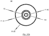
- the second lumen defined by the second catheter tube 42 has a diameter sufficient to accommodate a guide wire 180.
- the second catheter tube 42 may be made from a rigid material including, for example, nitinol, stainless steel or a rigid plastic material (see Fig. 10b ).
- the material of the distal end section of the second catheter tube 42 may have an increased flexibility compared to the material of the proximal end section in order to allow the distal end section of the catheter shaft 30 to pass the aortic arch during insertion of the catheter tip 10.
- the guiding tube 52 may be a 17F-catheter tube and the first catheter tube 32 may be a 12F-catheter tube.
- the distal end section of the second catheter tube 42 terminates in a soft catheter end tip 25 having an atraumatic shape.
- the soft catheter end tip 25 is provided with a channel aligned with the second lumen defined by the second catheter tube 42 such that a guide wire 180 accommodated within the second lumen of the second catheter tube 42 may pass through the channel of the soft catheter end tip 25.
- the second sleeve-shaped member 21 of the catheter tip 10 is connected to the soft catheter end tip 25 such that the opened end of the second sleeve-shaped member 21 faces in the proximal direction opposite to the direction of the soft catheter end tip 25 and to the second catheter tube 42.
- the stent holder tube 62 is made of a rigid material, for example, a rigid plastic material, stainless steel or nitinol.
- the distal end of the stent holder tube 62 terminates in the stent holder 15 which is also made of a rigid material, for example, a rigid plastic material or stainless steel.
- the passageway defined by the stent holder tube 62 is aligned with a channel which passes through the stent holder 15. In this way, the second catheter tube 42 is accommodated in the passageway of the stent holder tube 62 and the channel of the stent holder 15 such as to be moveable relative to the stent holder tube 62 and the stent holder 15.
- the first catheter tube 32 is made of a bendable but inelastic material.
- the first catheter tube 32 may be at least partly made of a braided or non-braided catheter tube.
- the first catheter tube 32 shall be adapted to transfer compression and tension forces from the first operating means 71 of the handle 70 to the first sleeve-shaped member 11 of the catheter tip 10 without overly changing its total length.
- the distal end of the first catheter tube 32 terminates at a flared section as a transition to the section defining the first sleeve-shaped member 11 of the catheter tip 10.
- the flared section and the first sleeve-shaped member 11 may be formed integrally and may be connected to the distal end section of the first catheter tube 31.
- the flared section may constitute the first sleeve-shaped member 11 of the catheter tip 10.
- the first sleeve-shaped member 11 and the flared section of the first catheter tube 31 may be all of the same material and originating from the same raw tube prior to a widening process so that the flared section and the first sleeve-shaped member 11 are the same elements.
- the insertion system 100 further comprises a guiding tube 52 having a cross-section greater than the cross-section of the first catheter tube 32.
- the guiding tube 52 defines a passageway and is disposed concentrically and coaxially with the first catheter tube 32, the stent holder tube 62 and the second catheter tube 42 such that the first catheter tube 32 with the stent holder tube 62 and the second catheter tube 42 accommodated therein is at least partly accommodated within the passageway defined by the guiding tube 52, wherein the first catheter tube 32 is moveable relative to the guiding tube 52.
- the guiding tube 52 terminates proximal to the catheter tip 10 wherein the cross-section of proximal end section of the guiding tube 52 shall be the same as or less than the cross-section of the flared section provided at the proximal end of the first catheter tube 32 so that a smooth transition from the first sleeve-shaped member 11 of the catheter tip 10 to the guiding tube 52 may be achieved (see Fig. 9 ).
- the proximal end section of the guiding tube 52 terminates distal to the handle 70.
- the proximal end section of the guiding tube 52 may be detached / disconnected from the handle 70 so that the handle 70 as well as the first and second catheter tubes 32, 42 and the stent holder tube 62 together with catheter tip 10 may be moved relative to the guiding tube 52.
- the distal end of the guiding tube 52 is formed such that the flared section provided at the distal end section of the first catheter tube 32 may abut on the distal end of the guiding tube 52 without abrupt transition.
- the guiding tube 52 may be of a thin material such as to allow length deformation of the guiding tube 52 upon transfer of compression and tension forces.
- the material of the guiding tube 52 shall have sufficient stiffness in order to mechanically avoid kinking of the flexible sections of the distal portion of the catheter shaft 30 during insertion of the catheter tip 10.
- the proximal end of the guiding tube 52 is releasably connectable to the body 70' of the handle 70.
- the guiding tube 52 may have a double-function:
- the guiding tube 52 serves as a distal extension of the body 70' of the handle 70 relative to which the first and second operating means 71, 81 are moveable for manipulating the first and second sleeve-shaped members 11, 21 of the catheter tip 10.
- the position of the stent holder 15 relative to the native heart valve of the patient may be changed by moving the guiding tube 52 connected to the handle 70.
- the guiding tube 52 may serve as an introducer tube, i.e. as a portal for passing the catheter tip 10 of the catheter system 1 into the patient's body and up to the heart.
- an inlet port 53 may be provided at a proximal end section of the guiding tube 52 for injection of fluids into the guiding tube 52.
- a check valve may be provided at the proximal end section of the guiding tube 52 to prevent fluid from leaking out of the guiding tube 52.
- the catheter tip 10 of the insertion system 100 is advanced, for example, via the aorta to the implantation site.
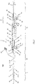
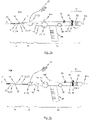
- Fig. 1 shows a part-sectioned representation of an exemplary embodiment of an insertion system 100 designed for transfemoral or transarterial access.
- an insertion system 100 may comprise a catheter system 1 and a handle 70 connected to the proximal end section of the catheter system 1.
- the catheter system 1 comprises a catheter tip 10 and a catheter shaft 30 for connecting the catheter tip 10 to the handle 70.
- the catheter tip 10 has a seat portion for accommodating a stent (see Figs. 12a-c ) in its collapsed state as well as a stent holder 15 for releasably fixing the stent.
- the seat portion of the catheter tip 10 is constituted by a first sleeve-shaped member 11 and a second sleeve-shaped member 21.
- the sleeve-shaped members 11, 21 of the catheter tip 10 are movable relative to each other and relative to the stent holder 15.
- the catheter shaft 30 comprises first force transmitting means 31, second force transmitting means 41 and guiding means 51.
- the first and second force transmitting means 41 31, 41 of the catheter system 1 are realized as flexible, elongated catheter tubes 32, 42.
- Each of the first and second catheter tubes 32, 42 defines a separate lumen.
- the guiding means 51 is realized as guiding tube 52 defining a passageway within which the first and second catheter tubes 32, 42 are received such as to be movable relative to the guiding tube 52.
- the guiding tube 52 has a distal end which terminates proximal to the catheter tip 10.
- the first catheter tube 32 has a length which is the same as, or substantially similar to the length of the second catheter tube 42.
- the first catheter tube 32 terminates at its distal end in a flared section as a transition to the section with wider cross-section defining the first sleeve-shaped member 11 of the catheter tip 10.
- the wider section of the first catheter tube 32 is formed integrally with the distal end section of the first catheter tube 32.
- the wider section has a length greater than the length of a collapsed stent to be accommodated in the catheter tip 10.
- the first force transmitting means 31 of the catheter system 1 is constituted by a first catheter tube 32 defining a first lumen
- the second force transmitting means 41 is constituted by a second catheter tube 42 defining a second lumen.
- the second catheter tube 42 has a cross-section less than the cross-section of the first catheter tube 32, wherein the first catheter tube 32 is disposed concentrically and coaxially with the second catheter tube 42.
- the cross-section of the catheter tip 10 is greater than or equal to the cross-section of the guiding tube 52.
- the guiding tube 52 has a cross-section which is greater than the cross-section of the part of the first catheter tube 32 which is received within the guiding tube 52.
- the cross-section of the catheter tip 10 is greater than the cross-section of the guiding tube 52.
- a check valve may be provided for preventing fluid from leaking out of the guiding tube 52.
- an inlet port 53 may be provided at the proximal end section of the guiding tube 52 for injection of fluids into the guiding tube 52.
- fluids such as saline solution may be injected through the inlet port 52 to flush the interior passageway of the guiding tube 52 and to reduce the incidence of blood clotting.
- a stopcock may be attached to the inlet port 53 to maintain the port 53 in a closed position when the port 53 is not being accessed to flush the passageway of the guiding tube 52.
- the guiding tube 52 is movable relative to the handle 70 and the first and second catheter tubes 32, 42. This provides a grip for the user who can hold the catheter shaft 30 at its proximal end section during positioning of the catheter tip 10 and during manipulation of the sleeve-shaped element 11 of the catheter tip 10.
- the user can hold the guiding tube 52, and in particular the proximal end section of the guiding tube 52 for supporting the movement of the first sleeve-shaped element 11 of the catheter tip 10 relative to the handle 70 such that the outer sheath of the catheter system 1 need not be held by the user or kinked.
- a handle 70 is utilized, said handle 70 comprising first and a second operating means 71, 81, which are connected by means of corresponding first and second force transmission means 31, 41 of the catheter shaft 30 to the first and second sleeve-shaped member 21s 11, 21 of the catheter tip 10.
- the first operating means 71 has a first pusher 73 which is functionally connected to the first slide 74.
- the first slide 74 is guided in a first guide 72 in the longitudinal direction L of the handle 70.
- the distal-side end of the first guide 72 defines the first stop 75 and the proximal-side end of the first guide 72 the second stop 76, which define the overall longitudinal displacement that can be effected with the first operating means 71.
- a locking element 77' may be positioned between the distal-side and the proximal-side end of the first guide 72, which defines the additional stop 77.
- the second operating means 81 of the handle 70 shown in Fig. 1 has a second pusher 83, which is functionally connected to a second slide 84.
- the second slide 84 is guided in a longitudinal guide (second guide 82) between a first stop 85 and a second stop 86.
- the second slide 84 is connected by means of the second force transmission means 41 with the second sleeve-shaped member 21 of the catheter tip 10.
- the second slide 84 is moved in the longitudinal direction L of the handle 70 from the first stop 85 to the second stop 86. This movement effects a longitudinal displacement of the second sleeve-shaped member 21 of the catheter tip 10 connected via the second force transmission means 41 with the second operating means 81.
- the second operating means 81 is equipped with a securing element 89, which may connect the second slide 84 with the body 70' of the handle 70 when in use.
- a longitudinal displacement of the second slide 84 to the second stop 86 is possible following removal or deactivation of the securing element 89.
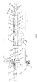
- Fig. 2 shows a further embodiment of a handle 70 of an insertion system 100 designed for transfemoral or transarterial access in a part-sectioned side view.
- the construction and mode of operation of the first and second operating means 81 71, 81 of the embodiment of the handle 70 shown in Fig. 2 is comparable in structural and functional respects to the handle 70 as previously described with reference to Fig.1 .
- elements in Fig. 2 that are generally similar to previously described elements have the same reference numbers compared with the reference numbers in Fig. 1 previously used for the similar elements.
- the handle 70 in accordance with Fig. 2 is provided with a third operating means 96 in the form of a wheel, by means of which a flexural link region 34 of the catheter shaft 30 can be controlled.
- a flexural link region 34 of the catheter shaft 30 can be controlled.
- the catheter shaft 30 is only optionally provided with such flexural link region 34. Rather, the material of the distal end section of the catheter shaft 30 may have an increased flexibility compared to the material of the proximal end section in order to allow the distal end section of the catheter shaft to pass 30 the aortic arch during insertion of the catheter tip.
- the third operating element 96 preferably has a detent device 100, to allow a set deflection of the flexural link region 34 of the catheter shaft 30 to be fixed.
- a suitable catch mechanism on the hand wheel of the third operating means 96, which cooperates with the body 70' of the handle 70.
- the flexural link region 34 of the catheter shaft 30 to be connected to the third operating means 96 by way of a control wire 35 whereby, on an actuation of the third operating means 96 via the control wire 35 a tensile forces is exerted on the flexural link region 34, which produces the deflection of the flexural link region 34 (see Fig. 3b ).
- the third operating means 96 for deflecting a flexural link region 34 of the catheter shaft 30 in case the catheter shaft 30 is provided with such a flexural link region 34.
- the handle 70 of the insertion system 100 designed for transarterial or transfemoral access may be provided with a pretensioning device, shown in Fig. 2 .
- a pretensioning device With such a pretensioning device, a constant tensile force may be exerted via the second operating means 81 on the second sleeve-shaped member 21 of the catheter tip 10.
- the pretensioning device may have a compression spring 97, permanently stressed along its spring axis, which is prestressed between a first stop 97a connected to the body 70' of the handle 70 and a second stop 97b connected to the proximal end region of the second operating means 81.
- a permanent, previously defined or definable tensile force is exerted on the second sleeve-shaped member 21 of the catheter tip 10.
- the pretensioning device implemented with the spring 97 in the embodiment in accordance with Fig. 2 may be advantageous when the catheter shaft 30 is bent during the implantation procedure, for example, when the catheter tip 10 of the insertion system 100 is inserted through the aorta.
- the outer fibres of the catheter shaft 30 are shortened. This can be compensated appropriately with the aid of the pretensioning device.
- the outer fibres of the catheter shaft 30 radially spaced from the neutral fibres are shortened.
- the second force transmission means 41 which connects the second operating means 81 with the second sleeve-shaped member 21 in the insertion system 100, normally runs along the neutral fibre of the catheter shaft 30, a bending contraction inevitably occurs when the catheter shaft 30 is bent, having the result that, despite fixing of the first operating means 71, the first sleeve-shaped member 11 of the catheter tip 10 is displaced relative to the stent holder 15 in a proximal direction.
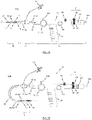
- FIG. 3a , b A further exemplary embodiment of an insertion system 100 designed for transarterial / transfemoral access is shown in Figs. 3a , b.
- Elements in Figs. 3a , b that are generally similar to previously described elements have the same reference numbers compared with the reference numbers in Figs. 1 and 2 previously used for the similar elements.
- the insertion system 100 shown in Figs. 3a, b comprises a catheter system 1 of the kind as previously described with reference to Fig. 1 , i.e. a catheter system 1 having a catheter tip 10 and a catheter shaft 30 which is provided with a first catheter tube 32 acting as first force transmitting means 31, a second catheter tube 42 acting as second force transmitting means 41, and a guiding tube 52 acting as guiding means 51.
- the catheter shaft 30 utilized in the exemplary embodiment of the insertion system 100 depicted in Fig. 1 the catheter shaft 30 of the insertion system 100 shown in Figs. 3a, b is provided with a flexural link region 34 of the kind as previously described with reference to Fig. 2 .
- the insertion system 100 shown in Figs. 3a , b is provided with a different embodiment of a handle 70 which is used in order to manipulate the first and second sleeve-shaped members 11, 21 of the catheter tip 10.
- the end region of the handle 70 is in the form of a turning mechanism 98 (rotatable means), with which the second force transmission means 41 of the catheter shaft 30 can be twisted with the distal-side end tip 25 and the second sleeve-shaped member 21 of the catheter tip 10 fastened to it about the longitudinal axis L of the catheter tip 10.
- the second sleeve-shaped member 21 of the catheter tip 10 is connected by means of a loose bearing to the stent holder 15, allowing transmission of a turning moment between the second sleeve-shaped member 21 and the stent holder 15, without allowing transmission of any tensile or compression forces acting in the direction of the longitudinal axis L of the catheter tip 10.
- the stent holder 15 also turns correspondingly about the longitudinal axis L.
- the turning mechanism 98 preferably allows the stent holder 15 to twist through approximately 120°.
- the rotation of a stent housed in the catheter tip 10, and particularly the positioning hoops already released in the second functional state of the insertion system 100 can be controlled, facilitating precise positioning of the already expanded positioning hoops of the stent in the pockets of the insufficient, native heart valve.
- the rotation movement of the stent holder 15 about the longitudinal axis L of the catheter tip 10 that can be effected with the turning mechanism 98 exhibits a previously definable, preferably small delay in reaction to a turning moment initiated by means of the turning mechanism 98.
- the embodiment of the handle 70 shown in Fig. 3a is equipped with a third operating means 96 in the form of a wheel, with which a flexural link 34, preferably provided at the distal end region of the catheter shaft 30, can be deflected.
- a device for force transmission (control wire 35 - see Fig. 8 ) which is connected on one side to the flexural link regions 34 preferably provided at the distal end region of the catheter shaft 30 and, on the other side, to the third operating means 96 of the handle 70 implemented in the embodiment shown in Fig. 3 as a hand wheel.
- the device for force transmission as a control wire 35, which is passed through the inside of the first transmission means 31 and preferably at the distal end of the flexural link region 34 or at the proximal end of the catheter tip 10 (see Fig. 8 ) to have a directed effect on the curvature of the flexural link region 34.
- a control wire 35 which is passed through the inside of the first transmission means 31 and preferably at the distal end of the flexural link region 34 or at the proximal end of the catheter tip 10 (see Fig. 8 ) to have a directed effect on the curvature of the flexural link region 34.
- With the tensile forces that can be exerted on the flexural link region 34 with the aid of the control wire 35 it is possible to obtain a defined curvature of the distal end region of the catheter shaft 30. This is a particular advantage during transarterial / transfemoral access when navigating the aortic arch.
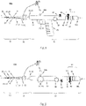
- FIG. 4 and 5 Further exemplary embodiments of an insertion system 100 which is suitable for transarterial / transfemoral access to the implantation location are shown in Figs. 4 and 5 .
- Elements in Figs. 4 and 5 that are generally similar to previously described elements have the same reference numbers compared with the reference numbers in Figs. 1 , 2 and 3a, b previously used for the similar elements.
- Figs. 4 and 5 differ first and foremost in relation to the implementation of the corresponding operating means 71, 81 of the handle 70.
- the insertion system 100 in accordance with Fig. 4 has a handle 70 with which the first operating means 71, which is used for manipulation of the first sleeve-shaped member 11 of the catheter tip 10, is similar to a trigger of a revolver.
- the user such as a physician who carries out the treatment may hold the handle 70 at the grip 88, while the first operating means 71 in the form of a trigger of a revolver is operated with the index finger of the hand holding it.
- a handle 70 is used which corresponds in structural and functional respects to the handle 70 used with the insertion system 100 in Fig. 3 with the exception of the grip 88 provided in the embodiment in accordance with Fig. 3 .
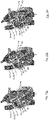
- FIG. 6a-d A description is given in the following, with reference to Figs. 6a-d and Figs. 7a-d , of the functional coaction of the components of an insertion system 100, which is suitable for a transarterial or transfemoral access to the implantation location.
- Elements in Figs. 6a to 6d and Figs. 7a to 7d that are generally similar to previously described elements have the same reference numbers compared with the reference numbers in Figs. 1 to 5 previously used for the similar elements.
- FIGs. 6a to 6d for illustrating the procedure for loading a stent into the catheter tip 10 of the insertion system 100.
- Figs. 7a to 7d the stepwise release of a stent mounted in the catheter tip 10 of the insertion system 100 is illustrated.
- the handle 70 for the transarterial / transfemoral insertion system 100 has a wheel rotatably mounted in the handle 70 which is functionally connected to the first sleeve-shaped member 11 of the catheter tip 10 associated with the first operating means 71 via a corresponding first force transmission means 31, so that force can be directly transmitted from the first operating means 71 in the form of the wheel to the first sleeve-shaped member 11 of the catheter tip 10.
- the first operating means 71 of the handle 70 in accordance with Fig. 6 and Fig. 7 can turn between a first stop and a second stop, in order to execute a definable longitudinal displacement stroke on the first sleeve-shaped member 11 of the catheter tip 10.
- the first operating means 71 of the handle 70 is provided with a additional stop between the first and second stop which cooperates, on one side with the first stop and on the other up with the second stop so that, on actuation of the first operating means 71, a longitudinal displacement of the first sleeve-shaped member 11 of the catheter tip 10 can be effected relative to the stent holder 15 of the catheter tip 10, consisting of two defined separate steps.
- the additional stop associated with the first operating means 71 is in the form of a locking element 77' positioned removably in the flow of force between the wheel and the first sleeve-shaped member 11 of the catheter tip 10, interrupting direct force transmission from the wheel to the first sleeve-shaped member 11 of the catheter tip 10.
- the additional stop associated with the first operating means 71 it is possible for the additional stop associated with the first operating means 71 to be in the form of a locking element restricting the free rotation of the wheel between the first and the second stop.
- the first operating means 71 of the handle 70 used with the insertion system 100 designed for transarterial / transfemoral access not to be a wheel, but to be implemented as a pusher mechanism.
- the second operating means 81 has a second slide 84 guided in a second guide 82 and functionally connected to a second pusher 83.
- This second slide 84 which is guided in the interior of the handle 70 and therefore cannot be seen in the view of Figs. 6 and 7 , is functionally connected to the second sleeve-shaped member 21 of the catheter tip 10 associated with the second operating means 81 by means of a second force transmission means 41 so that, on actuation of the second operating means 81, force is directly transmitted from the second slide 84 to the second sleeve-shaped member 21 of the catheter tip 10.
- the second operating means 81 can be displaced between a first position (Pos. 1) and a second position (Pos. 2) in the longitudinal direction of the handle 70, whereby the longitudinal displacement stroke that can be thus effected via the second force transmission means 41 is transferred directly to the second sleeve-shaped member 21 of the catheter tip 10.
- the first and second positions are each defined with the aid of a first and a second stop 85, 86.
- a securing element 89 is provided, associated with the second operating means 81, which is removably located on the second guide 82 and which blocks longitudinal displacement of the (second) slide 84 associated with the second operating means 81 when used.
- the handle 70 which is used with the transarterial / transfemoral insertion system 100 of the embodiment shown in Figs. 6 and 7 further exhibits an optional grip 88, which facilitates the operability of the handle 70 and in particular the operating conformity of the handle 70.
- the grip 88 is preferably releasably connected to the body 70' of the handle 70 and can optionally be fixed at different positions on the body 70' of the handle 70.
- the catheter tip 10 In relation to the construction of the catheter tip 10 which is used, for example, with the insertion system 100 shown in Figs. 6 and 7 and which allows transarterial / transfemoral access of a stent housed in the catheter tip 10 to the implantation location, it can be seen from Figs. 6 and 7 that the catheter tip 10 has a stent holder 15 for releasably fixing of, for example, the second retaining region of a stent that can be housed in the catheter tip 10.
- the retaining elements 16 of the stent holder 15 in the form of a crown are provided at the proximal end of the stent holder 15.
- the catheter tip 10 of the insertion system 100 designed for transarterial / transfemoral access comprises a mounting device for mounting a heart valve stent, where required, with a heart valve prosthesis fastened to it.
- the mounting device of the catheter tip 10 consists of a first sleeve-shaped member 11, particularly for accommodating the positioning hoops of a stent, and a second sleeve-shaped member 21, in particular for accommodating the heart valve prosthesis fastened to it, when required.
- the first operating means 71 of the handle 70 co-operates in the embodiment according to Figs. 6 and 7 with the first sleeve-shaped member 11 of the catheter tip 10 so that, on actuation of the first operating means 71, by transfer of a defined longitudinal displacement stroke, a previously definable longitudinal displacement of the first sleeve-shaped member 11 can be effected relative to the stent holder 15.
- the insertion system 100 according to Figs.
- the second operating means 81 of the handle 70 co-operates with the second sleeve-shaped member 21 of the catheter tip 10 so that, on actuation of the second operating means 81, by transfer of a defined longitudinal displacement stroke, a previously definable longitudinal displacement of the second sleeve-shaped member 21 of the catheter tip 10 relative to the stent holder 15 can be effected.
- the second sleeve-shaped member 21, which is used to house the retaining hoops of the stent with, where required, the heart valve prosthesis fastened to them, is located at the distal end region of the catheter tip 10, while the first sleeve-shaped member 11 is located between the second sleeve-shaped member 21 and the handle 70.
- the second force transmission means 41 which connects the second operating means 81 of the handle 70 to the second sleeve-shaped member 21 of the catheter tip 10, is preferably in the form of an inner catheter running inside the interior of the catheter or tube system.
- the second sleeve-shaped member 21 On actuation on the second operating means 81, the second sleeve-shaped member 21 can be moved relative to the stent holder 15 in the longitudinal direction L of the catheter tip 10 in a distal direction, thus away from the handle 70, while, on actuation of the first operating means 71 of the handle 70, the first sleeve-shaped member 11 of the catheter tip 10 can be moved relative to the stent holder 15 in the longitudinal direction L of the catheter tip 10 in a proximal direction, and thus towards the handle 70.
- FIG. 7a An embodiment of a transarterial / transfemoral insertion system 100 is shown in its four different functional states in Figs. 7a to 7d .
- the insertion system 100 is shown in its first functional state in Fig. 7a , in which the catheter shaft 30 with the catheter tip 10 and, where required, with the stent accommodated in it can be inserted into the patient transarterially or transfemorally and advanced via the aorta to the implantation site.
- the catheter tip 10 is completely closed, whereby the two sleeve-shaped members 11, 21 of the catheter tip 10 overlap telescopically.
- the respective diameters of the sleeve-shaped members 11, 21 are chosen so that the folded-up retaining hoops of a stent, with the heart valve prosthesis fastened to them where required, can be housed in the second sleeve-shaped member 21.
- the folded-up positioning hoops of the stent housed between the second sleeve-shaped member 21 and the first sleeve-shaped member 11 are held together in their folded form.
- the second retaining region of the stent is shown in the first functional state of the insertion system 100, as shown in Fig. 7a , with the stent holder 15 fixed at the proximal end of the catheter tip 10.
- the retaining elements (retaining rings etc.) provided at the second retaining region of the stent are engaged with retaining elements 16 of the stent holder 15.
- the retaining elements 16 of the stent holder 15 are covered by the first sleeve-shaped member 11 of the catheter tip 10 in the first functional state shown in Fig. 7a , so that an engagement between retaining elements provided on the second retaining region of a stent and retaining elements 16 of the stent holder 15 would be possible.
- the first functional state of the insertion system 100 shown in Fig. 7a is maintained during the transarterial insertion procedure.
- the insertion system 100 is transferred from the first functional state shown in Fig. 7a to the second functional state shown in Fig. 7b , by transferring the first operating means 71 (shown in the embodiment of the wheel in Fig. 7 ) from the first position into the second position.
- the longitudinal displacement stroke transferred by actuation of the first operating means 71 to the first sleeve-shaped member 11 of the catheter tip 10 effects a displacement of the first sleeve-shaped member 11 relative to the stent holder 15 in the proximal direction, thus towards the handle 70.
- the longitudinal displacement stroke executed on the first sleeve-shaped member 11 of the catheter tip 10 during the transition from the first functional state (see Fig. 7a ) to the second functional state (see Fig. 7b ) by the first operating means 71 of the handle 70 via a corresponding first force transmission means 31 is previously defined so that the first sleeve-shaped member 11 is displaced relative to the stent holder 15 in the proximal direction just so far that the positioning hoops of a stent housed in the catheter tip 10 would be released, though the distal end of the first sleeve-shaped member 11 of the catheter tip 10 would still cover the retaining elements 16 of the stent holder 15, so that the engagement between the retaining elements provided at the second retaining region of the stent and the retaining elements 16 of the stent holder 15 would be secure.
- the first retaining region of a stent housed in the catheter tip 10 with the heart valve prosthesis fastened to it would continue to be housed in its folded together state in the sleeve-shaped element of the second sleeve-shaped member 21.
- the positioning hoops of a stent housed in the catheter tip 10 released in the second functional state of the insertion system 100 are opened as a result of the radial forces acting on them and can thus be positioned in the pockets of the insufficient native heart valve.
- the insertion system 100 is transferred from the second functional state shown in Fig. 7b into the third functional state shown in Fig. 7c . This is done my manipulation of the second operating means 81, after the securing element 89 associated with the second operating means 81 has been removed.
- the second sleeve-shaped member 21 of the catheter tip 10 associated with the second operating means 81 is moved relative to the stent holder 15 by a previously established longitudinal displacement stroke defined with the second operating means 81 in a distal direction, thus away from the handle 70.
- the longitudinal displacement stroke acting on the second sleeve-shaped member 21 is chosen so that the sleeve-shaped member 21 no longer covers the first retaining region of a stent housed in the catheter tip 10 with the heart valve prosthesis fastened to it, where required, and thus releases the first retaining region of the stent. Due to the action of the radial forces, the distal retaining region of the stent with the heart valve prosthesis attached to it, where required, unfolds completely.
- the distal end region of the first sleeve-shaped member 11 continues to cover the retaining elements 16 of the stent holder 15, so that the engagement between the retaining elements of a stent housed in the catheter tip 10 and the retaining elements 16 of the stent holder 15 is secure and the proximal retaining region of the stent is in its folded-up state.
- This anchorage of the stent to the catheter tip 10 of the insertion system 100 allows an explantation of a stent that is already partially unfolded by returning the insertion system 100 from the third functional state, by appropriate manipulation of the second operating means 81 of the handle 70, to the second functional state and then by suitable actuation of the first operating means 71 transfer to the first functional state.
- the insertion system 100 is transferred from the third functional state shown in Fig. 7c into the fourth functional state shown in Fig. 7d , by turning the first operating means 71 of the handle 70 further from the second position to the third position after removal of the securing element 79 (locking element).
- This manipulation of the first operating means 71 that can be effected after removal of the securing element 79 results in a further defined movement of the first sleeve-shaped member 11 relative to the stent holder 15 of the catheter tip 10 in a proximal direction, thus towards the handle 70.
- the longitudinal displacement stroke executed on the first sleeve-shaped member 11 is chosen so that the distal end of the first sleeve-shaped member 11 no longer covers the retaining elements 16 of the stent holder 15, as a result of which an engagement between the retaining elements of a stent housed in the catheter tip 10 and the retaining elements 16 of the stent holder 15 can be released, which would also lead to a complete release of the second retaining region of the stent and a complete separation of the stent from the catheter tip 10 and correspondingly to a complete unfolding of the stent.
- FIG. 6a The four functional states of the insertion system 100 designed for transarterial / transfemoral access, previously described with reference to Figs. 7a to 7d , are shown in reverse order in Figs. 6a to 6d to clarify the procedure for loading a stent into the catheter tip 10 of the insertion system 100.
- Comparison between Figs. 6a to 6d and Figs. 7a to 7d show that the insertion system 100 can be loaded with a heart valve stent by transferring the insertion system 100, starting from its fourth functional state in accordance with Fig. 6a (see Fig. 7d ), into its third functional state in accordance with Fig. 6b (see Fig.
- FIG. 9 for describing an exemplary embodiment of the catheter tip 10. Elements in Fig. 9 that are generally similar to previously described elements have the same reference numbers compared with the reference numbers in Figs. 1 to 7 previously used for the similar elements.
- catheter shaft 30 An exemplary embodiment of a catheter shaft 30 is described in the following, with reference to the illustration in Fig. 9 .
- This catheter shaft 30 can be used with an insertion system 100 designed for transarterial or transfemoral access.
- Fig. 9 shows an exemplary embodiment of a shaft for an insertion system 100 in a cross-sectional elevation.
- the catheter shaft 30 exhibits a first force transmission means 31 in the form of a first catheter tube 32, whereby this first catheter tube 32 is used to connect the first operating means 71 of the handle 70 to the first sleeve-shaped member 11 of the catheter tip 10.
- the first force transmission means 31 implemented as a first catheter tube 32 may be clamped between a screw cap 74' and the first slide 74 of the first operating means 71 and consequently is permanently connected to the first slide 74.
- the distal-side end region of the first catheter tube 32 merges into the first sleeve-shaped member 11 of the catheter tip 10 in the form of the stent sheath.
- the second force transmission means 41 of the catheter shaft 30 used with an insertion system 100 designed for transarterial or transfemoral access is preferably implemented as a second catheter tube 42.
- the proximal-side end region of the second catheter tube 42 is connected to the second operating means 81 of the handle 70.
- the distal-side end region of the second catheter tube 42 is connected to the catheter end tip 25 of the catheter tip 10.
- the second sleeve-shaped member 21 of the catheter tip 10 is permanently connected by means of its distal-side end to the end tip 25 of the catheter tip 10 so that, on actuation of the second operating means 81 via the force transmission means 41 in the form of the second catheter tube 42, a tensile or compressive force can be transmitted to the second sleeve-shaped member 21 of the catheter tip 10.
- the exemplary embodiment of the catheter tip 10 further comprises a stent holder 15 at the proximal end section of the catheter tip 10.
- the stent holder 15 has a passageway extending there through.
- the distal end section of the second force transmitting means 41 (second catheter tube 42) passes through the passageway of the stent holder 15 and terminates at the second sleeve-shaped member 21.
- the respective sleeve-shaped members 11, 21 of the catheter tip 10 can be manipulated by corresponding operating means 71, 81 of a handle 70 (not shown in Fig. 9 ).
- the first sleeve-shaped member 11 of the catheter tip 10 is connected with a first operating means 71 of a handle 70 by using a first force transmitting means 31.
- the second sleeve-shaped member 21 of the catheter tip 10 is connected to a second operating means 81 of the handle 70 by using a second force transmitting means 41.
- the first force transmitting means 31 is constituted by a first catheter tube 32 defining a first lumen
- the second force transmitting means 41 is constituted by a second catheter tube 42 defining a second lumen.
- the second catheter tube 42 has a cross-section less than the cross-section of the first catheter tube 32, wherein the first catheter tube 32 is disposed concentrically and coaxially with the second catheter tube 42.
- the distal end section of the second catheter tube 42 passes through the opened front face of the second sleeve-shaped member 21 and terminates in a cone-shaped end tip 25 of the catheter system 1, wherein the base of this cone-shaped end tip 25 defines the distal front face of the second sleeve-shaped member 21.
- the end tip 25 of the catheter system 1 is preferably a soft catheter end tip, for example a soft polymeric catheter end tip.
- the first catheter tube 32 terminates after an intermediate flared section in a section with wider cross-section defining the first sleeve-shaped member 11 of the catheter tip 10.
- the flared section is formed integrally with the distal end section of the first catheter tube 32.
- the flared section has a length greater than the length of a collapsed stent to be accommodated in the catheter tip 10, wherein the difference in the length between the flared section and the stent in its collapsed state represents the length of the stent holder 15.
- the distal end of the guiding tube 52 terminates proximal to the catheter tip 10.
- the guiding tube 52 defines a passageway within which the first and second catheter tube 42 32, 42 are received such as to be movable relative to the guiding tube 52.
- the distal end of the guiding tube 52 may be tapered such that it abuts the first catheter tube 32 in one of its possible positions on the catheter shaft 30.
- Fig. 10a is a cross-sectional view of a catheter shaft 30 according to an exemplary embodiment.
- the second force transmission means 41 in the form of the second catheter tube 42 runs along the neutral fibre of the catheter shaft 30 inside the first catheter tube 32.
- the space between the first catheter tube 32 and the second catheter tube 42 may be filled with a filler material, so that a filler body 40 is formed.
- the filler material is preferably a relatively elastic plastic material to allow the catheter shaft 30 to bend overall.
- the filler body 40 is used for connecting the stent holder 15 of the catheter tip 10 to the body 70' of the handle 70.
- a stent holder tube 62 may be used for connecting the stent holder 15 of the catheter tip 10 to the body 70' of the handle 70.
- the stent holder tube 62 may have a distal end connected to the stent holder 15, a proximal end connected to the body 70' of the handle 70 and a passageway extending through the stent holder tube 62.
- the stent holder tube 62 has a cross-section less than the cross-section of the first catheter tube 32 and greater than the cross-section of the second catheter tube 42, wherein the first catheter tube 32 is disposed concentrically and coaxially with the stent holder tube 62 thereby accommodating the stent holder tube 62 such that the first catheter tube 32 is moveable relative to the stent holder tube 62.
- the passageway of the stent holder tube 62 shall have a diameter sufficient to accommodate the second catheter tube 42 such that the second catheter tube 42 is moveable relative to the stent holder tube 62.
- the filler body 40 (or the stent holder tube 62) may be connected by means of a fixing 87 to the body 70' of the handle 70.
- the proximal-side end region of the stent holder 15 attaches at the distal-side end region of the filler body 40 (see Fig. 8 ).
- the connection between the stent holder 15 and the filler body 40 is preferably chosen so that it allows rotation of the stent holder 15 relative to the filler body 40. This is especially necessary for control of the rotation of the positioning hoops of the already partially released stent during the implantation procedure (see Fig. 12a ).
- the complete catheter system 1 can be rotated for appropriate positioning of a stent connected with the catheter tip 10 and, in particular the positioning hoops of an already partially released stent during the implantation procedure. This is possible due to an appropriate transmission of torque and the flexibility of the catheter system 1.
- a stent holder tube 62 is used for connecting the stent holder 15 of the catheter tip 10 to the body 70' of the handle 70, the stent holder tube 62 may be rotatable relatively to the first and second catheter tubes 32, 42 about the longitudinal axis L of the catheter system 1. This will be described later in more detail with reference to the exemplary embodiment depicted in Fig. 10b .
- the second force transmission means 41 in the form of the second catheter tube 42 can be turned about the longitudinal direction L, for example, by means of a rotatable cap 98 which may be provided at the proximal end region of the handle 70. This rotary movement is transferred from the second catheter tube 42 direct to the end tip 25 of the catheter tip 10 and thus to the second sleeve-shaped member 21 of the catheter tip 10.
- the second catheter tube 42 runs through the body of the stent holder 15 and cooperates with the stent holder 15 with the aid of a suitable toothing, to transmit a turning moment exerted by means of the rotary cap of the handle 70 on the second catheter tube 42 to the stent holder 15, while tensile or compression forces acting in the longitudinal direction L of the catheter tip 10 are not transmitted from the second catheter tube 42 to the stent holder 15.
- a least one fluid channel 43 may be provided in the filler body 40 of the catheter shaft 30, connected at its proximal-side end to an injection adapter 99b (see Fig. 2 ) and at its distal-side end correspondingly to the catheter tip 10, consequently ensuring supply of fluid to the catheter tip 10 and draining of fluid from the catheter tip 10.
- a channel may be provided in the filler body 40 for accommodating a control wire (control wire 35 - see Fig. 8 ), with an operating means may cooperate with a flexural link region, in case the catheter shaft 30 is provided with such a flexural link region (see Fig. 3 and Fig. 2 ).
- a control wire control wire 35 - see Fig. 8
- an operating means may cooperate with a flexural link region, in case the catheter shaft 30 is provided with such a flexural link region (see Fig. 3 and Fig. 2 ).
- the distal-side end of a control wire 35 is fixed to the proximal-side end region of the stent holder 15.
- Fig. 10b is a cross-sectional view of a catheter shaft 30 according to an alternative exemplary embodiment.
- the first force transmitting means 31 may be constituted by a first catheter tube 32 defining a first lumen and the second force transmitting means 41 is constituted by a second catheter tube 42 defining a second lumen.
- the second catheter tube 42 may have a cross-section less than the cross-section of the first catheter tube 32.
- the first catheter tube 32 may be disposed concentrically and coaxially with the second catheter tube 42 and the second catheter tube 42 is received within the first lumen defined by the first catheter tube 32.
- a stent holder tube 62 is provided for connecting the stent holder 15 to the handle 70, said stent holder tube 62 having a distal end connected to the stent holder 15 and a proximal end connected to a body 70' of the handle 70.
- the stent holder tube 62 may have a cross-section less than the cross-section of the first catheter tube 32.
- the first catheter tube 32 may be disposed concentrically and coaxially with both, the second catheter tube 42 on the one hand and the stent holder tube 62 on the other hand.
- the stent holder tube 62 has a cross-section less than the cross-section of the first catheter tube 32 and greater than the cross-section of the second catheter tube 42 such that the stent holder tube 62 is received within the first lumen defined by the first catheter tube 32 and the second catheter tube 42 is received within a passageway defined by the stent holder tube 62.
- the passageway defined by the stent holder tube 62 has a diameter sufficient to accommodate the second catheter tube 42 such that the second catheter tube 42 is moveable relative to the stent holder tube 62.
- the second lumen defined by the second catheter tube 42 has a diameter sufficient to accommodate a guide wire 180.
- the second catheter tube 42 may be made from a rigid material including, for example, nitinol, stainless steel or a rigid plastic material.
- the material of the distal end section of the second catheter tube 42 may have an increased flexibility compared to the material of the proximal end section in order to allow the distal end section of the catheter shaft 30 to pass the aortic arch during insertion of the catheter tip 10.
- the guiding tube 52 may be a 17F-catheter tube and the first catheter tube 32 may be a 12F-catheter tube.
- the stent holder tube 62 is made of a rigid material, for example, a rigid plastic material, stainless steel or nitinol.
- the distal end of the stent holder tube 62 terminates in the stent holder 15 which is also made of a rigid material, for example, a rigid plastic material or stainless steel.
- the passageway defined by the stent holder tube 62 is aligned with a channel which passes through the stent holder 15. In this way, the second catheter tube 42 is accommodated in the passageway of the stent holder tube 62 and the channel of the stent holder 15 such as to be moveable relative to the stent holder tube 62 and the stent holder 15.
- the embodiments of the insertion system 100 designed for transarterial / transfemoral access may have a first injection adapter 99a at the proximal end of the handle 70.
- This first injection adapter 99a is used for flushing the insertion system 100 and as outlet of a guide wire 180, with the aid of which the actual introduction of the catheter shaft 30 with the catheter tip 10 provided at the distal end of the catheter shaft 30 into the body of the patient is simplified.
- the catheter shaft 30, the catheter tip 10 and the handle 70 are thereby threaded into the guide wire 180 and pushed along it, for example into the aorta and to the heart of the patient.
- a second injection adapter 99b may further be provided, by means of which a liquid coolant etc. can be passed, for example, via the fluid channels 43 (see Fig. 10a ) formed in the interior of the catheter shaft 30 to the catheter tip 10.
- a liquid coolant etc.
- a stent accommodated in the catheter tip 10 can be appropriately cooled while the catheter tip 10 is being advanced to the implantation location, as long as the insertion system 100 is in its first functional state, in which the catheter tip 10 is completely enclosed by the telescopically arranged sleeve-shaped members 11 and 21.
- the provision of cooling that can be produced with the second injection adapter 99b for the stent accommodated in the catheter tip 10 is a particular advantage when a shape memory material is used as stent material and when the stent can deform under the effect of an external stimulus from a temporary form to a permanent form, whereby the temporary form exists in the first configuration of the stent (in the folded-up state, when the stent is accommodated in the catheter tip 10) and the permanent form exists in the second configuration of the stent (in the expanded state of the stent after release of the stent from the catheter tip 10).
- the guiding tube 52 is preferably made from a material allowing the guiding tube 52 to be capable of traversing a tortuous pathway in the body of the patient without kinking.
- the guiding tube 52 may include an inner lubricious liner, an outer polymeric jacket, and a coil reinforcement between the inner and outer layers.
- first and second catheter tubes 32, 42 of the catheter shaft 30 are preferably made from flexible, sterilizable materials. These materials may include, for example, polyurethane, silicone, polyvinyl chloride (PVC) nylon and/or polyether block amide, e.g. Pebax ® .
- the first catheter tube 32 and/or second catheter tube 42 are/is at least partly made from a less rigid material than the guiding tube 52.
- the first catheter tube 32 and/or the second catheter tube 42 are/is at least partly made of a braided wire construction.
- the stent holder tube 62 may also be at least partly made of a braided wire construction.
- FIG. 12a to 12c A preferred embodiment of a medical device for treatment of a heart valve stenosis and/or heart valve insufficiency in a patient is described in the following with reference to Figs. 12a to 12c .
- the medical device exhibits an insertion system 100 designed for transarterial / transfemoral access, as has been described in detail previously, for example, with reference to Figs. 1 to 10 .
- the medical device has an expandable heart valve stent 150 mounted in the catheter tip 10 of the insertion system 100, to which a heart valve prosthesis 160 to be implanted is fastened.
- the stent 150 In the first functional state, not shown, the stent 150 exhibits a first, previously definable configuration, in which it is in its folded-together state.
- the stent 150 is designed to adopt a second previously definable configuration in the implanted state, in which it exists in its expanded state.
- the stent 150 is transferred sequentially, following a previously definable sequence of events in steps from its first previously defined configuration into its second previously defined configuration.
- the stent 150 that is used with the medical device in accordance with the depiction in Figs. 12a to 12c exhibits a first retaining region, to which the heart valve prosthesis 160 is attached. Further, the stent 150 comprises a second retaining region with three retaining elements 151, each in the configuration of retaining rings, which can be brought in to a releasable engagement with the retaining elements 16 of the stent holder 15 provided in the catheter tip 10.
- the stent 150 has three retaining hoops 153 to accommodate the heart valve prosthesis 160 and three positioning hoops 154 for automatic positioning of the stent 150 at the implantation site, whereby the respective positioning hoops 154 of the stent 150 are designed in functional and structural respects to engage the pockets 170 of the native heart valve during the implantation procedure and in the implanted state of the stent 150, in particular from the second functional state of the insertion system 100.
- each positioning hoop 154 and its associated retaining hoop 153 has an essentially U or V-shaped structure, which is closed towards the distal end of the stent 150.
- the stent 150 which together with the insertion system 100 forms the basis of the medical device, is especially suitable for insertion into the body of a patient with the aid of the insertion system 100 with minimal invasiveness.
- the distinctive feature of the stent 150 is that the three positioning hoops 154 of the stent 150 undertake the function of automatic positioning of the stent 150 with the heart valve prosthesis 160 attached to it in the aorta of the patient.
- the positioning hoops 154 have radiused head sections, which engage in the pockets 170 of the insufficient heart valve to be replaced by the heart valve prosthesis during positioning of the stent 150 at the implantation site.
- the provision of a total of three positioning hoops 154 takes care of the necessary positioning accuracy in the rotary direction.
- the catheter tip 10 and the catheter shaft 30 of the transarterial or transfemoral insertion system 100 has been inserted by a puncture of the groin artery of the patient and the catheter tip 10 has been advanced to the implantation site with the aid of a guide wire 180.
- the insertion system 100 to be used is shown already in its second functional state in Fig. 12a .
- the second functional state of the insertion system 100 designed for transarterial or transfemoral access has been described previously, for example with reference to Fig. 7b .
- the first sleeve-shaped member 11 of the catheter tip 10 has already moved by a first predetermined amount of movement in a proximal direction, and thus towards the handle 70, leading to a release of the positioning hoops 154 of the stent 150.
- These already expanded positioning hoops 154 of the stent 150 shown in Fig. 12a are positioned - where necessary by a suitable rotation of the stent holder 15 of the catheter tip 10 - in the pockets 170 of the native heart valve position.
- the insertion system 100 is transferred from its second functional state (see Fig. 7b ) into its third functional state (see Fig. 7c ).
- FIG. 12b shows the insertion system 100 in accordance with Fig. 12a , in which the second sleeve-shaped member 21 has been displaced in a distal direction so that the first retaining region of the stent 150 with the retaining hoops 153 and the heart valve prosthesis 160 attached to them are released.
- These components are opened as a result of the radial forces attacking them, whereby the old heart valves are clamped between the positioning hoops 154 and the retaining hoops 153.
- Fig. 12 shows the effect of the transfer of the insertion system 100 into its fourth functional state on the heart valve prosthesis 160 and the stent 150.
- the first sleeve-shaped member 11 of the catheter tip 10 has been displaced further in a proximal direction, as a result of which the anchorage of the retaining elements 151 on the second retaining region of the stent 150 is released. This has the result that that the second retaining region of the stent 150 can also expand and press against the vessel wall.
- the old (insufficient) heart valve is pressed against the vessel wall at the same time due to the self-expanding characteristic of the stent 150, as can be seen in particular in Fig. 12c .
- the semilunar heart valves of the insufficient, native heart valve are clamped between the positioning hoops 154 and the retaining hoops 153 because of the expansion of the stent 150, in addition to which the heart valve prosthesis 160 located on the first retaining region of the stent 150 is optimally positioned and is stably anchored.
- the disclosed solutions provide an improved insertion system 100 with the stent mountable in the catheter tip 10 of the insertion system 100.
- the stent may be inserted transarterially by the special insertion system 100 and can be optimally positioned, so that a heart valve prosthesis sewn on the first retaining region of the stent can undertake the function of the insufficient or stenosed native heart valve.
- the radial forces developed due to the self-expanding characteristic of the stent ensure a secure anchoring in the area of the aorta.
- the catheter system 1 of the insertion system 100 is preferably an 18 to 21F introducer, which is compatible with 21F-insertion tubes and a 0.035" guide wire 180.
- the length of the catheter system 1 for transarterial access should be at least 100 cm.
- the optionally provided flexural link region at the distal region of the catheter system 1 is preferably approximately 30 cm.
- FIG. 13a A further embodiment of a catheter tip 10 for an insertion system for transfemoral / transarterial insertion of an expandable heart valve stent is shown in its four different functional states in Figs. 13a to 13d .
- the catheter tip 10 is shown in its first functional state in Fig. 13a , in which the catheter shaft with the catheter tip 10 and, where required, with the stent accommodated in it can be inserted into the patient transarterially or transfemorally and advanced via the aorta to the implantation site.
- the catheter tip 10 is completely closed, whereby the two sleeve-shaped members 11, 21 of the catheter tip 10 abut.
- the two sleeve-shaped members 11, 21 of the catheter tip 10 have an equal outer cross-section diameter, thereby not forming a step in the state depicted in Fig. 13a .
- the respective inner diameters of the sleeve-shaped members 11, 21 are chosen so that the folded-up retaining hoops of a stent, with the heart valve prosthesis fastened to them where required, can be housed in the second sleeve-shaped member 21.
- the folded-up positioning hoops of the stent housed between the second sleeve-shaped member 21 and the first sleeve-shaped member 11 are held together in their folded form.
- the second retaining region of the stent is fixed with the stent holder 15 at the proximal end of the catheter tip 10.
- the retaining elements (retaining rings etc.) provided at the second retaining region of the stent are engaged with retaining elements 16 of the stent holder 15.
- the retaining elements 16 of the stent holder 15 are covered by the first sleeve-shaped member 11 of the catheter tip 10 in the first functional state shown in Fig. 13a , so that an engagement between retaining elements provided on the second retaining region of a stent and retaining elements 16 of the stent holder 15 would be possible.
- the first functional state of the catheter tip 10 shown in Fig. 13a is maintained during the transarterial insertion procedure.
- the catheter tip 10 is transferred from the first functional state shown in Fig. 13a to the second functional state shown in Fig. 13b , by transferring the first operating means of the handle (first operating means 71 shown in the embodiment of the wheel in Fig. 7 ) from the first position into the second position.
- the longitudinal displacement stroke transferred by actuation of the first operating means 71 to the first sleeve-shaped member 11 of the catheter tip 10 effects a displacement of the first sleeve-shaped member 11 relative to the stent holder 15 in the proximal direction, thus towards the handle 70.
- the longitudinal displacement stroke executed on the first sleeve-shaped member 11 of the catheter tip 10 during the transition from the first functional state (see Fig. 13a ) to the second functional state (see Fig. 13b ) by the first operating means 71 of the handle 70 via a corresponding first force transmission means 31 is previously defined so that the first sleeve-shaped member 11 is displaced relative to the stent holder 15 in the proximal direction just so far that the positioning hoops of a stent housed in the catheter tip 10 would be released, though the distal end of the first sleeve-shaped member 11 of the catheter tip 10 would still cover the retaining elements 16 of the stent holder 15, so that the engagement between the retaining elements provided at the second retaining region of the stent and the retaining elements 16 of the stent holder 15 would be secure.
- the first retaining region of a stent housed in the catheter tip 10 with the heart valve prosthesis fastened to it would continue to be housed in its folded together state in the sleeve-shaped element of the second sleeve-shaped member 21.
- the positioning hoops of a stent housed in the catheter tip 10 released in the second functional state of the catheter tip 10 are opened as a result of the radial forces acting on them and can thus be positioned in the pockets of the insufficient native heart valve.
- the catheter tip 10 is transferred from the second functional state shown in Fig. 13b into the third functional state shown in Fig. 13c . This is done my manipulation of the second operating means 81 of the handle, after the securing element 89 associated with the second operating means 81 has been removed.
- the second sleeve-shaped member 21 of the catheter tip 10 associated with the second operating means 81 is moved relative to the stent holder 15 by a previously established longitudinal displacement stroke defined with the second operating means 81 in a distal direction, thus away from the handle 70.
- the longitudinal displacement stroke acting on the second sleeve-shaped member 21 is chosen so that the sleeve-shaped member 21 no longer covers the first retaining region of a stent housed in the catheter tip 10 with the heart valve prosthesis fastened to it, where required, and thus releases the first retaining region of the stent. Due to the action of the radial forces, the distal retaining region of the stent with the heart valve prosthesis attached to it, where required, unfolds completely.
- the distal end region of the first sleeve-shaped member 11 continues to cover the retaining elements 16 of the stent holder 15, so that the engagement between the retaining elements of a stent housed in the catheter tip 10 and the retaining elements 16 of the stent holder 15 is secure and the proximal retaining region of the stent is in its folded-up state.
- This anchorage of the stent to the catheter tip 10 of the insertion system 100 allows an explantation of a stent that is already partially unfolded by returning the catheter tip 10 from the third functional state, by appropriate manipulation of the second operating means 81 of the handle 70, to the second functional state and then by suitable actuation of the first operating means 71 transfer to the first functional state.
- the catheter tip 10 is transferred from the third functional state shown in Fig. 13c into the fourth functional state shown in Fig. 13d , by turning the first operating means 71 of the handle 70 further from the second position to the third position after removal of the securing element 79 (locking element).
- This manipulation of the first operating means 71 that can be effected after removal of the securing element 79 results in a further defined movement of the first sleeve-shaped member 11 relative to the stent holder 15 of the catheter tip 10 in a proximal direction, thus towards the handle 70.
- the longitudinal displacement stroke executed on the first sleeve-shaped member 11 is chosen so that the distal end of the first sleeve-shaped member 11 no longer covers the retaining elements 16 of the stent holder 15, as a result of which an engagement between the retaining elements of a stent housed in the catheter tip 10 and the retaining elements 16 of the stent holder 15 can be released, which would also lead to a complete release of the second retaining region of the stent and a complete separation of the stent from the catheter tip 10 and correspondingly to a complete unfolding of the stent.
- a stent holder tube 62 is used for connecting the stent holder 15 of the catheter tip 10 to the body 70' of the handle 70.
- the stent holder tube 62 has a distal end connected to the stent holder 15, a proximal end connected to the body 70' of the handle 70 and a passageway extending through the stent holder tube 62.
- an extension portion 62' of the stent holder tube 62 is provided, said extension portion extending from the distal end of the stent holder 15 to a support section 63.
- the support section 63 may be a tapered portion which is completely accommodated in the second sleeve-shaped member 21 when the catheter tip 10 is in its first and second functional state (cf. Figs. 13a, b ).
- the stent holder tube 62 and its extension 62' have a cross-section less than the cross-section of the first catheter tube 32 and greater than the cross-section of the second catheter tube 42 (not shown in Figs. 13a-e ), wherein the first catheter tube 32 is disposed concentrically and coaxially with the stent holder tube 62 thereby accommodating the stent holder tube 62 such that the first catheter tube 32 is moveable relative to the stent holder tube 62.
- the passageway of the stent holder tube 62 shall have a diameter sufficient to accommodate the second catheter tube 42 such that the second catheter tube 42 is moveable relative to the stent holder tube 62.
- Fig. 13e shows a side elevation of the embodiment of the catheter tip 10 in accordance with Fig. 13a-d , whereby the catheter tip 10 is in its state after releasing a stent housed in the catheter tip 10 and ready to be removed again from the body of the patient.
- the first sleeve-shaped member 11 is pushed by manipulation of the first operating means 71 of the handle 70 such that the first sleeve-shaped member 11 is in its most distal position, in which the distal end of the first sleeve-shaped member 11 abuts against the proximal end of the second sleeve-shaped member 21 without any gap or step there between.
- the distal end of the first sleeve-shaped members 11 is supported by the already mentioned support section 63.
Landscapes
- Health & Medical Sciences (AREA)
- Cardiology (AREA)
- Engineering & Computer Science (AREA)
- Biomedical Technology (AREA)
- Life Sciences & Earth Sciences (AREA)
- Transplantation (AREA)
- Heart & Thoracic Surgery (AREA)
- Vascular Medicine (AREA)
- Oral & Maxillofacial Surgery (AREA)
- Animal Behavior & Ethology (AREA)
- General Health & Medical Sciences (AREA)
- Public Health (AREA)
- Veterinary Medicine (AREA)
- Mechanical Engineering (AREA)
- Prostheses (AREA)
- Media Introduction/Drainage Providing Device (AREA)
Description
- The present disclosure concerns a catheter system for introducing an expandable heart valve stent into the body of a patient. The disclosure further concerns an insertion system comprising a catheter system and a handle for inserting an expandable heart valve stent into the body of a patient, as well as a medical device for treatment of a heart valve defect, in particular a heart valve failure or a heart valve stenosis in a patient, wherein the medical device has an insertion system and an expandable heart valve stent accommodated in the catheter tip of the insertion system.
- In medical technology, there has been an endeavour over a long period to close a heart valve defect, such as an aortic valve insufficiency or an aortic valve stenosis, non-surgically by means of a transarterial interventional access by catheter, thus technically without an operation. Various insertion systems and stent systems have been proposed, with different advantages and disadvantages, which in part can be introduced into the body of a patient transarterially by means of a catheter insertion system, though a specific system has not prevailed up to the present.
- The term used here "heart valve stenosis and/or heart valve insufficiency" shall generally be understood here as a congenital or acquired functional disorder of one or several heart valves. A valve defect of this type can affect each of the four heart valves, whereby the valves in the left ventricle (aortic and mitral valve) are certainly more frequently affected than those of the right heart (pulmonary and tricuspid valve). The functional disorder can result in narrowing (stenosis) or inability to close (insufficiency) or a combination of the two (combined cardiac defect).
- With all known interventional systems for implantation of heart valve prosthesis, an expandable stent system is moved transarterially to an insufficient heart valve. A stent system of this type consists, for example, of a self-expanding or balloon-expanding anchoring support (also termed "heart valve stent" or "stent" in the following), to which the actual heart valve prosthesis is fastened, preferably at the distal retaining region of the anchoring support.
- In the medical devices previously known from the state-of-the-art, however, it has become apparent that the implantation procedure of a stent system to which the heart valve prosthesis is attached is relatively complicated, difficult and expensive. Apart from the complicated implantation of the heart valve prosthesis as a replacement for an insufficient native heart valve, there is the fundamental risk of incorrect positioning of the stent or heart valve prosthesis with the medical devices used up to the present, which cannot be corrected without more extensive operative intervention.
- The problem addressed by the present disclosure is the fact that medical technology does not currently offer any insertion system in particular for transarterial or transfemoral implantation of a self- or balloon-expandable heart valve stent with a heart valve prosthesis attached to it in which, on the one hand, the insertion system enables a minimally invasive implantation of the heart valve prosthesis in a predictable manner and, on the other, dispensing with the need to use a heart-lung machine during the operation on the anaesthetized patient. Consequently the operative intervention can be designed to be especially cost-effective and, in particular, to reduce the physical and mental stress on the patient. In particular, there is a lack of a medical device for implantation of heart valve prostheses that can also be used for patients on whom, due to their age, an operation cannot be carried out without the aid of a heart-lung machine.
- Because of the increasing number of patients requiring treatment, there is also a growing need for an insertion system with which a minimally invasive intervention can be made on a patient for treatment of a heart valve stenosis and/or heart valve insufficiency in a precisely predictable way, whereby the success of the operation is in particular no longer significantly dependent on the skill and experience of the heart surgeon or radiologist carrying out the treatment.
- This situation also applies to operations in which heart valve prostheses with stent systems are implanted with the aid of a so-called balloon catheter system.
- It is also regarded as problematic that, when using systems already known from the state-of-the-art by means of which a heart valve prosthesis can be implanted in the body of the patient with minimal invasiveness, incorrect positioning of the heart valve prosthesis or the associated heart valve stent can frequently only be avoided when the heart surgeon or radiologist is especially experienced. It is indeed known, for example, to insert a heart valve stent with a heart valve prosthesis attached to it into the body of a patient as far as the heart via the aorta, whereby self-expansion or balloon-expansion of the heart valve stent is initiated by external manipulation when the implantation location is reached, which should lead to a secure anchorage and precise positioning of the heart valve prosthesis; such heart valve stents cannot usually be removed in a simple way, however, and their position cannot usually be corrected once the stent has expanded.
- Accordingly, there is basically a risk with the known systems that if, for example, the self-expansion or balloon-expansion of the heart valve stent with the attached heart valve prosthesis is initiated in a non-optimum position, due to a slip by the doctor carrying out the treatment or other technical circumstances such as stent foreshortening, this position can only be corrected appropriately by means of a major, in particular operative, intervention, which must frequently be carried out on the open heart.
- For example, a heart valve stent for heart valve prosthesis is described in document
WO 2004/019825 A1 . With this heart valve stent, distal-end support arches or hoops and positioning arches or hoops are provided, which can be inserted into the pockets of the native heart valve of a patient so that the heart valve stent can be positioned by means of the support hoops. Additional so-called commissural hoops can also be formed on the known heart valve stent which, together with the support arches, clamp parts of the old heart valve once the stent has unfolded to that the stent can be positioned and anchored as a result of this clamping action. - Although the support arches provided on the anchoring stent enable improved positioning of the heart valve prosthesis to be implanted, there is nevertheless still a risk of incorrect implantation and of the heart valve prosthesis being incapable of functioning correctly or functioning but unsatisfactorily. For example, it may be found during the intervention that the heart valve prosthesis or the heart valve stent is not optimally dimensioned for the patient. In such cases, even if only the respective distal support or positioning arches of the stent are in their expanded state, removal (explantation) or repositioning of the heart valve stent with the heart valve prosthesis is no longer possible and there exists an increased mortality risk for the particular patient.
- The aortic arch in the human body represents a further problem for such interventions, since it has to be accessed during insertion through the aorta. When this is done, the catheter tip and the respective catheter must undergo a change of direction of approximately 180° over a relatively small radius, usually about 50 mm, without causing injury or damage to the vessel wall.
-
WO2008138584 A1 relates to catheter system for introducing an expandable heart valve stent into the body of a patient. - The invention is defined by
claim 1. Preferred embodiments are defined by the dependent claims. Further embodiments disclosed herein are for exemplary purpose only and do not form part of the claimed invention. - The objective of the disclosure is to propose a catheter system for introducing an expandable heart valve stent into the body of a patient and for positioning the stent at a desired implantation site, wherein the catheter system is designed to enable the implantation of a heart valve prosthesis attached to a heart valve stent in the optimum implantation location in a sequence of events defined before the intervention.
- Secondly, the objective is to propose a medical device for treatment of a heart valve stenosis and/or heart valve insufficiency, comprising a catheter system and an expandable heart valve stent mounted in the catheter tip of the insertion system and which is designed to reduce the risk to the patient on implantation of the heart valve prosthesis.
- In accordance with a preferred embodiment, the present disclosure provides a catheter system for introducing an expandable heart valve stent into the body of a patient, the catheter system comprising a catheter tip and a catheter shaft. The catheter tip of the catheter system has a seat portion for accommodating the stent to be introduced into the patient's body in its collapsed state. The catheter system has further a stent holder for realisably fixing the stent to the catheter tip. The seat portion of the catheter tip is constituted by a first sleeve-shaped member and a second sleeve-shaped member, said sleeve-shaped members being moveable relative to each other as well as relative to the stent holder of the catheter tip. The catheter shaft comprises first force transmitting means, second force transmitting means and guiding means. The distal end section of the first force transmitting means is connected to the first sleeve-shaped member of the catheter tip and the proximal end section of the first force transmitting means is connectable to a first operating means of a handle. The distal end section of the second force transmitting means is connected to the second sleeve-shaped member of the catheter tip and the proximal end section of the second force transmitting means is connectable to a second operating means of the handle.
- Preferably, the cross-section of second sleeve-shaped member of the catheter tip is equal to or less than the cross-section of the first sleeve-shaped member of the catheter tip. In case the cross-section of second sleeve-shaped member of the catheter tip is less than the cross-section of the first sleeve-shaped member, the second sleeve-shaped member is at least partly accommodatable within the first sleeve-shaped member in a telescopic manner. This may allow minimizing the cross-section of catheter tip. At the same time, an expandable heart valve stent may be released from the catheter tip of the catheter system in a step-wise manner. In case the cross-section of second sleeve-shaped member of the catheter tip is less than the cross-section of the first sleeve-shaped member, the second sleeve-shaped member and the first sleeve-shaped member - once brought together - can reside on an internal support structure, e.g. a cylindrical insert, resulting in a step and gap free transition.
- According to one aspect of the present disclosure, the catheter system comprises guiding means having a guiding tube with a passageway extending there between. The guiding means serves for guiding of the catheter shaft has a distal end, a proximal end and a passageway extending there between. The first and second force transmitting means are at least partly received within this passageway such as to be moveable relative to the guiding means. The guiding tube of the guiding means has a length such that the distal end of the guiding means terminates proximal to the catheter tip of the catheter system. Moreover, guiding tube has a cross-section less than the cross-section of the catheter tip.
- According to another aspect of the present disclosure, the catheter system further comprises a guide wire suited for guiding the catheter tip of the catheter system to an implantation site. The guide wire is designed to be advanced into a patient's vasculature independently from the catheter system and, in particular, independently from the catheter tip of the catheter system.
- In accordance with another preferred embodiment, an insertion system for inserting an expandable heart valve stent is disclosed.
- Whilst the term "vascular" refers to the blood vessels of the patient's body including both veins and arteries, in a preferred embodiment, the insertion system is for transarterial delivery using the arteries, although it is conceivable that in other embodiments transvenous delivery via a vein could be used.
- In particular, the vascular insertion system comprises a catheter system with a catheter tip, a catheter shaft and a handle. The catheter tip has a seat portion for accommodating a stent to be inserted in its collapsed state and a stent holder for releasably fixing the stent. The proximal end of the catheter system is attached to the handle and the distal end is attached to the catheter tip. The catheter system comprises the catheter shaft for connecting the catheter tip to the handle of the insertion system, the distal end section of the catheter shaft being flexible enough such that the catheter tip and the distal end section of the catheter shaft may be easily navigated through the anatomy and especially through the aortic arch during insertion through the aorta of the patient.
- The handle has at least one first and one second operating means with which the catheter tip of the insertion system may be appropriately manipulated so that an expandable stent housed in the catheter tip may be released from the catheter tip in steps or in a defined or definable sequence of events.
- The catheter tip of the catheter system and at least the distal part of the catheter shaft are typically inserted into the femoral artery and moved up the descending thoracic aorta until the catheter tip is positioned in the ascending aorta. The proximal end of the catheter shaft together with the handle attached thereto remains outside of the patient's body.
- In accordance with a preferred embodiment, the catheter tip has first and second housing portions termed "sleeve-shaped members" in the following, that may be manipulated with the handle. These sleeve-shaped members are used for accommodating specific portions of the stent. The first sleeve-shaped member is used for accommodating first functional components of the stent, for example retaining hoops of the stent (or alternatively positioning hoops of the stent), while the second sleeve-shaped member is used for accommodating the second functional components of the stent, for example, positioning hoops of the stent (or alternatively for accommodating retaining hoops of the stent).
- In relation to the handle provided for the insertion system, it is preferably provided that, on one hand, the first operating means cooperate with the first sleeve-shaped member of the catheter tip so that, on actuation of the first operating means, a previously definable longitudinal displacement of the first sleeve-shaped member may be effected relative to the stent holder and the guiding tube of the catheter shaft. On the other hand, the second operating means cooperates with the second sleeve-shaped member of the catheter tip so that a previously definable longitudinal displacement of the second sleeve-shaped member may be affected relative to the stent holder and the guiding tube of the catheter shaft.
- The cross-section of the second sleeve-shaped member is identical to the cross-section of the first sleeve-shaped member such that the sleeve-shaped members can completely enclose a stent accommodated in the catheter tip without a gap between the first and second sleeve-shaped members thereby providing a catheter tip having an atraumatic shape. In addition, the first and second sleeve-shaped members are movable relative to each other and relative to the stent holder.
- For this purpose, first force transmitting means with a distal end section connected to the first sleeve-shaped member and a proximal end section connected to first operating means of the handle are provided. In addition, second force transmitting means with a distal end section connected to the second sleeve-shaped member and a proximal end section connected to second operating means of the handle are provided. When manipulating the first and/or second operating means of the handle, the first and/or second sleeve-shaped members may be moved relative to each other and relative to the stent holder.
- In accordance with the preferred embodiment, the first force transmitting means is constituted by a first catheter tube defining a first lumen and the second force transmitting means is constituted by a second catheter tube defining a second lumen. The second catheter tube has a cross-section less than the cross-section of the first catheter tube. The first catheter tube is disposed concentrically and coaxially with the second catheter tube and the second catheter tube is received within the first lumen defined by the first catheter tube.
- Contrary to the first and second sleeve-shaped members of the catheter tip, however, the stent holder of the catheter tip is not moveable relative to the handle of the insertion system. Rather, the stent holder is connected to the handle by using a stent holder tube having a distal end connected to the stent holder and a proximal end connected to a body of the handle. The stent holder tube has a cross-section less than the cross-section of the first catheter tube. In particular, the first catheter tube is disposed concentrically and coaxially with both, the second catheter tube on the one hand and the stent holder tube on the other hand. Preferably, the stent holder tube has a cross-section less than the cross-section of the first catheter tube and greater than the cross-section of the second catheter tube such that the stent holder tube is received within the first lumen defined by the first catheter tube and the second catheter tube is received within a passageway defined by the stent holder tube. The passageway defined by the stent holder tube has a diameter sufficient to accommodate the second catheter tube such that the second catheter tube is moveable relative to the stent holder tube.
- The second lumen defined by the second catheter tube has a diameter sufficient to accommodate a guide wire. The second catheter tube is made from a rigid material including, for example, nitinol, stainless steel or a rigid plastic material. The material of the distal end section of the second catheter tube may have an increased flexibility compared to the material of the proximal end section in order to allow the distal end section of the catheter shaft to pass the aortic arch during insertion of the catheter tip.
- The distal end section of the second catheter tube terminates in a soft catheter end tip having an atraumatic shape. The soft catheter end tip is provided with a channel aligned with the second lumen defined by the second catheter tube such that a guide wire accommodated within the second lumen of the second catheter tube may pass through the channel of the soft catheter end tip. The second sleeve-shaped member of the catheter tip is connected to the soft catheter end tip such that the opened end of the second sleeve-shaped member faces in the proximal direction opposite to the direction of the soft catheter end tip and to the second catheter tube.
- The stent holder tube is made of a rigid material, for example, a rigid plastic material, stainless steel or nitinol. The distal end of the stent holder tube terminates in the stent holder which is also made of a rigid material, for example, a rigid plastic material or stainless steel. The passageway defined by the stent holder tube is aligned with a channel which passes through the stent holder. In this way, the second catheter tube is accommodated in the passageway of the stent holder tube and the channel of the stent holder such as to be moveable relative to the stent holder tube and the stent holder. The stent holder tube is provided for connecting the stent holder to the handle. For this purpose, the stent holder tube has a distal end connected to the stent holder and a proximal end connected to a body of the handle.
- The first catheter tube is made of a bendable but inelastic material. For example, the first catheter tube may be at least partly made of a braided or non-braided catheter tube. Hence, the first catheter tube has a stiff braid reinforced body similar to the catheter body described in
U.S. Pat. No. 4,665,604 . - The first catheter tube shall be adapted to transfer compression and tension forces from the first operating means of the handle to the first sleeve-shaped member of the catheter tip without overly changing of its total length. The distal end of the first catheter tube terminates at a flared section as the transition to the section defining the first sleeve-shaped member of the catheter tip. The flared section and the first sleeve-shaped member may be formed integrally and may be connected to the distal end section of the first catheter tube. Alternatively, the first sleeve-shaped member and the flared section of the first catheter tube may be all of the same material and originating from the same raw tube prior to a widening process so that the flared section and the first sleeve-shaped member are the same elements.
- The insertion system according to the preferred embodiment further comprises a guiding tube having a cross-section greater than the cross-section of the first catheter tube. The guiding tube defines a passageway and is disposed concentrically and coaxially with the first catheter tube, the stent holder tube and the second catheter tube such that the first catheter tube with the stent holder tube and the second catheter tube accommodated therein is at least partly accommodated within the passageway defined by the guiding tube, wherein the first catheter tube is moveable relative to the guiding tube. In particular, the guiding tube terminates proximal to the catheter tip wherein the cross-section of proximal end section of the guiding tube shall be substantially the same as or less than the cross-section of the flared section provided at the proximal end of the first catheter tube. The proximal end section of the guiding tube terminates distal to the handle. The proximal end section of the guiding tube may be detached/disconnected from the handle so that the handle as well as the first and second catheter tubes and the stent holder tube together with catheter tip may be moved relative to the guiding tube.
- The distal end of the guiding tube is formed such that the flared section provided at the distal end section of the first catheter tube may abut on the distal end of the guiding tube without abrupt transition. The guiding tube may be of a thin material such as to allow length deformation of the guiding tube upon transfer of compression and tension forces. The guiding tube material, however, shall have sufficient stiffness in order to mechanically avoid kinking of the flexible sections of the distal portion of the catheter shaft during insertion of the catheter tip.
- The proximal end of the guiding tube is releasably connectable to the body of the handle. In this way, the guiding tube may have a double-function:
In case, the proximal end of the guiding tube is connected to the handle, the guiding tube serves as a distal extension of the body of the handle relative to which the first and second operating means are moveable for manipulating the first and second sleeve-shaped members of the catheter tip. Hence, position of the stent holder relative to the native heart valve of the patient may be changed by moving the guiding tube connected to the handle. - In case, the proximal end of the guiding tube is not connected to the body of the handle, the guiding tube may serve as a portal for passing the catheter shaft of the catheter system into the patient's body from proximal of the catheter tip.
- In any case, the guiding tube has a length and is adapted such that the first catheter tube and the second catheter tube are moveable relative to each other and relative to the stent holder independent from any movement or activation of the guiding tube. In particular, the movement of the sleeve shaped members is independent from the presence or absence of the guiding tube. The length of the guiding tube is such that the sleeved shaped members and hence the first and second catheter tubes are moveable relative to each other and relative to the stent holder without interfering with the distal end of the guiding tube.
- An inlet may be provided at a proximal end section of the guiding tube for injection of fluids into the guiding tube. Furthermore, a check valve may be provided at the proximal end section of the guiding tube to prevent fluid from leaking out of the guiding tube.
- The guiding tube may have a length sufficient to protect the inner wall of the blood vessel through which the catheter tip passes. In addition, a separate introducer system (not belonging to the catheter system) may be provided. The introducer system then may serve as a portal for passing the complete catheter system from the catheter tip to the catheter shaft into the patient's body and up to the heart.
- In addition, the guiding tube reduces the compression force exerted on the first catheter tube that is inserted through the guiding tube. This increases manoeuvrability of the first catheter tube throughout the procedure in which the first catheter tube serves as force transmitting means for manipulating the first sleeve-shaped member of the catheter tip. A consequence thereof is that the frictional force acting on the first catheter tube is reduced compared with a catheter design which is not provided with a guiding tube. Moreover, moving the catheter tip after it has been advanced through the vascular system of a patient, is greatly improved while at the same time lowering the risk of injury of the patient.
- In accordance with the preferred embodiment, the guiding tube has a cross-section equal to or less than the cross-section of the catheter tip. In this regard, the guiding tube will have a length shorter than the length of the first and second catheter tubes such that the distal end of the guiding tube terminates proximal to the catheter tip. As will be appreciated, the guiding tube may not be removed from the catheter system in case the proximal end sections of the first and second catheter tube are connected to the respective operating means of a handle.
- The length of the guiding tube depends on the length of the first and second catheter tubes and will typically be between about 20 cm and 100 cm. Those skilled in the art will appreciate, however, that all dimensions provided herein are intended as examples only, and that the guiding tubes and catheter tubes of different dimensions may be substituted for a particular use. As already indicated, the first and second catheter tubes are moveable relative to each other and relative to the stent holder independent from the guiding tube. The movement of the sleeve shaped members is independent from the presence or absence of the guiding tube. In other words, the guiding tube does not serve for manipulating the sleeve-shaped members of the catheter tip. In particular, the guiding tube does not block the travel of the sleeve-shaped members.
- As will be appreciated, the guiding tube will be of a size, i.e. has an outer diameter, which will permit insertion in a patient's blood vessel (artery or vein) which is used for moving the stent transarterially or via a vein to an insufficient heart valve.
- The guiding tube may be capable of traversing tortuous pathways in the body of the patient without kinking. The guiding tube may include an inner lubricious liner, an outer polymeric jacket, and a coil reinforcement between the inner and the outer layers. This guiding tube may provide favourable flexibility without kinking or compression. One or more radiopaque bands or markers may be incorporated within the guiding tubes material to allow precise location of the guiding tubes distal end for positioning accuracy. Those skilled in the art will appreciate that other known materials may also be suitable for a particular purpose.
- In an embodiment disclosed herein, the catheter tip and the catheter shaft proximally connected to the catheter tip may be inserted into the patient's body by using a guide wire. The guide wire serves for guiding the catheter tip of the catheter system to an implantation site. Once in position above the aortic valve the guide wire may then be removed. Alternatively, the guide wire remains in the patient's body during implantation of a heart valve prosthesis accommodated in the catheter tip. Then, the guide wire is removed together with the catheter from the patient's body.
- The guide wire is designed to be advanced into a patient's vasculature independently from the catheter tip and the catheter shaft proximally connected to the catheter tip. In other words, the catheter tip together with at least the distal part of the catheter shaft and the guide wire are advanced as single units through the vasculature of the patient, respectively. Once the guide wire is placed, the catheter tip and the catheter shaft proximally connected to the catheter tip can be advanced over the guide wire directly to the particular site in the patient's cardiovascular system.
- In accordance with the present invention, a guide wire is advanced through the patient's vascular system, its direction being controlled and fluoroscopically monitored by the surgeon, until its distal end is at the desired location. Preferably, the guide wire is very small in diameter, thereby not presenting any substantial obstruction to blood flow in the blood vessel. After inserting the guide wire, the catheter tip together with the catheter shaft proximally connected to the catheter tip are advanced over the guide wire with the wire being received in the second lumen which is defined by the second catheter tube of the catheter shaft. The guide wire thus simply and automatically guides the catheter tip of the catheter system directly to the intended region, without requiring difficult, time consuming manipulations.
- In a preferred embodiment of the present disclosure, the guide wire has a diameter less than the diameter of the second lumen defined by the second catheter tube. This allows that the guide wire may be at least partly received within the second lumen defined by the second catheter tube for guiding the catheter tip, at least partly disposed about the guide wire, to the implantation site.
- In a preferred embodiment of the invention, the second lumen defined by the second catheter tube of the catheter shaft has a minimum dimension which is just slightly greater than the diameter of the guide wire. The maximum cross-sectional dimension of the second lumen is substantially larger than the cross-section of the guide wire. Thus, when the guide wire is disposed within the second lumen there will be substantial voids through the second lumen, on opposite sides of the guide wire through which fluids may be administered to the patient and through which blood pressure measurements may be taken. Such fluids may be administered and pressure measurements may be taken without removing the guide wire at all. By way of example, the cross-section of the guide wire preferably is of the order of no more than about fifty percent of the cross-sectional area of the second lumen.
- In order to implant a heart valve prosthesis accommodated in the catheter tip, the catheter tip and the catheter shaft proximally connected to the catheter tip are advanced over the guide wire. As the tip of the guide wire terminates in the left ventricle of the heart, pushing the guide wire may contact the left ventricular apex.
- In order to avoid any damage of the left ventricular apex when the guide wire is inserted, and to avoid any injury or damage to the vessel wall when the guide wire is inserted (advanced) through a vessel, the guide wire preferably has a flexible bumper at the leading end of the advancing guide wire, which minimizes the risk of trauma or injury to the delicate internal surfaces of the artery. The bumper is preferably highly flexible and with a smooth leading end. For example, the guide wire may terminate in a smoothly surfaced rounded tip, at the distal end of the guide wire. Alternatively, the distal end of the guide wire may have a j-hook shape or a hockey-stick shape, thereby reducing the risk of trauma.
- Since the guide wire and the catheter tip together with the catheter shaft proximally connected to the catheter tip are generally independently advanced into the vasculature, the guide wire must be sufficiently stiff throughout its length to prevent buckling. Furthermore, the guide wire shall have sufficient stiffness to track the delivery system (catheter tip and catheter shaft proximally connected to the catheter tip) around the aortic arch. On the other hand, at least the distal tip of the guide wire shall be soft enough to prevent puncture of the heart tissue.
- The guide wire may comprise a distal tip guide section and a proximal pull section. The pull section allowing for the tip guide section to be pulled out after final positioning of the catheter tip and having an optimal cross sectional area and size, is generally smaller than that of the tip guide section so as to assure minimum blood leakage at the insertion site. The tip guide section is capable of guiding the catheter through a patient's vasculature.
- The guide wire may, in an exemplary embodiment, be approximately 175 centimeters long so that it may be introduced through the femoral artery and have ample length to reach the patient's coronary region. The guide wire may include a small diameter main wire. This rotationally rigid main wire of the guide wire can be solid or tubular, as long as it is rigid torsionally so that it may transmit fully to the distal end a rotational motion imparted to the proximal end. The main wire has relatively little twist as its proximal end is rotated. Practically all rotation applied to the proximal end will be transmitted quickly to the very distal tip of the guide wire. Alternatively, the guide wire may be formed substantially from elongate helical springs.
- As already indicated, the aortic arch in the human body may represent a challenge for transfemoral implantation of a self- or balloon-expandable heart valve stent with a heart valve prosthesis attached to it, since it has to be accessed during insertion through the aorta. When this is done, the catheter tip and the catheter shaft proximally connected to the catheter tip must undergo a change of direction of approximately 180° over a relatively small radius, usually about 50 mm, without causing injury or damage to the vessel wall. For aiding the bending of the catheter tip and the catheter shaft proximally connected to the catheter tip when passing through the aortic arch and for supporting the catheter tip in accessing the ascending aorta, the guide wire may have a specific structure such as to make a U turn in the aortic arch. Hence, the guide wire may be programmed such that the guide wire takes a U-shape bend.
- In a preferred embodiment of the present disclosure, at least a distal section of the guide wire has a predefined curved configuration adapted to the curvature of the patient's aortic arch. The predefined curved configuration of at least the distal section of the guide wire is selected such as to push the catheter tip in the direction of the centre of the ascending aorta when the catheter tip is at least partly disposed about the distal section of the guide wire and transfemoral inserted into the patient's body.
- In this respect, the guide wire has a double-function: On the one hand, the guide wire serves for guiding the catheter tip of the catheter system to an implantation site. On the other hand, the guide wire serves for positioning the catheter tip in the centre of the ascending aorta when the catheter tip has accessed the ascending aorta. Then, positioning arches or hoops of the stent accommodated in the catheter tip may be easily inserted into the pockets of the native heart valve of a patient so that the heart valve stent can be easily positioned.
- In a preferred embodiment, at least the distal section of the guide wire exhibits a first predefinable shape before advancing the guide wire into the patient's vasculature and a second predefinable shape in the advanced state of said guide wire, wherein the second predefinable shape of the distal section of the guide wire corresponds to the predefined curved configuration of the distal section of the guide wire. For achieving this, the guide wire may consist at least partly of a shape memory material such that at least the distal section of the guide wire can transform from a temporary shape into a permanent shape under influence of an external stimulus, wherein the temporary shape of the distal section of the guide wire corresponds to the first shape and the permanent shape of the distal section of the guide wire corresponds to the second shape.
- A shape memory material, for example Nitinol, may be used as the material for at least the distal section of the guide wire. Such a shape memory material is preferably designed such that the guide wire can transform from a temporary shape into a permanent shape under the influence of an external stimulus. The temporary shape is thereby the first shape of the guide wire (i.e. the shape of the guide wire before inserting it into the patient's body), while the permanent shape is assumed in the second shape of the guide wire (i.e. in the inserted state of the guide wire). In particular, use of a shape memory material such as Nitinol, i.e. an equiatomic alloy of nickel and titanium, allows for a particularly gentle insertion procedure.
- It is conceivable of course that other shape memory materials, for example shape-memory polymers, are used as the material for at least the distal section of the guide wire. At least parts of the guide wire may be formed by using, for example, a polymer composite exhibiting a crystalline or semi-crystalline polymer network having crystalline switching segments. On the other hand, an amorphous polymer network having amorphous switching segments is also conceivable.
- When manufacturing the guide wire preferably made from a shape memory material, the permanent shape of the guide wire, i.e. the shape of the guide wire which is assumed in the inserted state of the guide wire, is formed. Once the desired shape has been formed, this shape is "fixed", this process being known as "programming". Programming may be effected by heating the guide wire, forming the guide wire into the desired shape and then cooling the guide wire. Programming may also be effected by forming and shaping the structure of the guide wire at lower temperature, this being known as "cold stretching." The permanent shape is thus saved, enabling the guide wire to be stored and implanted in a temporary, non-formed shape. If an external stimulus then acts on the stent structure, the shape memory effect is activated and the saved, permanent shape restored.
- A particularly preferred embodiment provides for the external stimulus to be a definable switching temperature. It is thus conceivable that the material of the guide wire needs to be heated to a higher temperature than the switching temperature in order to activate the shape memory effect and thus regenerate the saved permanent shape of the guide wire. A specific switching temperature can be preset by the relevant selection of the chemical composition of the shape memory material.
- It is particularly preferred to set the switching temperature to be in the range of between 10°C and the patient's body temperature and preferably in the range of between 10°C and room temperature (22°C). Doing so is of advantage, especially with regard to the guide wire which needs to be inserted in a patient's body. Accordingly, all that needs to be ensured in this regard when inserting the guide wire is that the guide wire is warmed up to room temperature or the patient's body temperature (37°C) at the site of implantation to activate the shape memory effect of the stent material.
- Alternatively, the guide wire may be made from another material (for example a platinum-tungsten alloy) which allows that the distal region of the guide wire can be bent manually by the surgeon and will retain its bent configuration when relaxed. This enables the guide wire to be controllably steered by rotation of the guide wire to direct the curved distal end selectively into the aortic arch and into the ascending aorta. Rotational control of the guide wire may be enhanced by bending the proximal end of the wire to form somewhat of a handle.
- In use, the surgeon may bend the distal region of the guide wire so that it will be biased toward and will assume somewhat of a curve when relaxed. When advanced through the patient's artery the degree of resilience at the distal region of the wire is such that the wire will straighten and follow the path of the artery quite easily. A progressively increased flexibility resulting from, for example, a continuous taper at the distal region of the guide wire may enhance the ability of the guide wire to flex from the pre-bent biased curve and follow the path of the blood vessel.
- When the distal end of the pre-bent, biased guide wire is at the descending aorta proximal of the aortic arch, the surgeon can steer it into the aortic arch and thereafter into the ascending arch by rotation of the guide wire by manipulating it from the proximal end.
- Alternatively, the guide wire may be inserted into the patient's body by using a guide catheter. The guide catheter may comprise a guide catheter tube defining a lumen for receiving the guide wire. The guide catheter may serve for inserting the guide wire. Once the guide catheter is introduced through the femoral artery and the aortic arch and has reached the patient's aortic valve region, the guide wire is released from the guide catheter by removing the guide catheter whereas the guide wire remains in the patient's body. In this case, the guide wire exhibits its first predefinable shape before releasing the guide wire from the guide catheter and its second predefinable shape after releasing the guide wire from the guide catheter. As already indicated, the second predefinable shape of the distal section of the guide wire is selected such that the distal section of the guide wire pushes the catheter tip in the direction of the centre of the ascending aorta when the catheter tip is at least partly disposed about the distal section of the guide wire and transfemoral inserted into the patient's body.
- According to one aspect of the present disclosure, at least the distal region of the guide wire is at least partly formed from a material having a high radiopacity. A relatively high degree of radiopacity of the distal region of the guide wire enhances fluoroscopic imaging of the guide wire as it is advanced through the patient's artery.
- The procedure for using the guide wire in accordance with the present invention involves initial placement and location of the guide wire in the femoral artery and the aortic arch. Once the guide wire is in place the catheter tip with the catheter shaft of the catheter system then may be advanced over the guide wire to a point where the stent accommodated in the catheter tip is in the ascending aorta proximal to the native aortic heart valve. This can be verified fluoroscopically because of the highly radiopaque characteristic of the catheter tip and/or guide wire and also by injecting radiopaque dye through, for example, a lumen of the catheter system. For this reason, the catheter tip of the catheter system may be provided with radiopaque markers which also facilitate fluoroscopic monitoring of its progress and position.
- In order to treat a heart valve stenosis and/or heart valve insufficiency in a patient, a medical device is disclosed. The medical device comprises an insertion system and an expandable heart valve stent accommodated in the catheter tip of the insertion system. While it is accommodated in the catheter tip of the insertion system, the stent adopts a first previously definable configuration. Outside the catheter tip or in the implanted state, however, the stent exists in a second previously definable configuration. The first configuration of the stent corresponds to the folded-up state, while the stent exists in its expanded state in the second configuration.
- A heart valve stent is used with the medical device, as described for example in the
European Patent Application No. 07 110 318 European Patent Application No. 08 151 963 - a first retaining region, to which a heart valve prosthesis can be attached;
- an opposing, second retaining region with at least one retaining element, for example in the form of retaining eyes or in the form of retaining heads, whereby at least one retaining element of the stent can be put in releasable engagement with the stent holder of the catheter tip forming part of the insertion system;
- at least one retaining hoop, to which a heart valve prosthesis can be fastened; and
- at least one and preferably three positioning hoops, which are designed to engage in pockets of the native heart valve in the implanted state of the stent, thus to enable automatic positioning of the stent in the aorta of the patient.
- In particular, an insertion system is proposed, with which an expandable heart valve stent with a heart valve prosthesis attached to this stent can be advanced to the implantation site in a particularly simple way, for example via the aorta of a patient being treated (transarterially or transfemorally). Preferably, during transarterial or transfemoral access by the catheter system, the whole free cross-section available within the aorta is not completely filled up, since the catheter tip provided at the distal end region of the catheter system, in which the stent can be accommodated with the heart valve prosthesis, can be made sufficiently small with respect to its external diameter.
- The expandable heart valve stent with the heart valve prosthesis attached to it can be accommodated temporarily during implantation in the folded-up state in the catheter tip of the insertion system, which is provided at the distal end region of the catheter system. The catheter system may be of a length sufficient to allow the catheter tip provided at the distal end region of the catheter system to be guided through the aorta to the patient's heart by insertion at the patient's groin.
- The insertion system designed for transarterial or transfemoral access is therefore suitable for inserting a heart valve stent with a heart valve prosthesis attached to it, transarterially or transfemorally into the body of the patient; for example, the catheter system of the insertion system is inserted with the catheter tip located at the distal end of the catheter system via puncture of the A. femoris communis (inguinal artery).
- In particular, with the insertion system designed for transarterial or transfemoral access, the catheter system may be designed so that it is both kink-resistant and flexible such that a bending radius of up to 4 cm, and preferably up to 3 cm, can be realised, at least at the distal end region of the catheter system.
- Preferred embodiments will be described with reference to the appended drawings below.
- Of these:
- Fig. 1:
- an embodiment of an insertion system for transfemoral / transarterial insertion of an expandable heart valve stent in a part-sectioned side elevation;
- Fig. 2:
- an embodiment of a handle for an insertion system for transfemoral / transarterial insertion of an expandable heart valve stent in a part-sectioned side elevation;
- Fig. 3a:
- an embodiment of an insertion system for transfemoral / transarterial insertion of a heart valve stent in a side elevation;
- Fig. 3b:
- a side elevation of the transfemoral / transarterial insertion system in accordance with
Fig. 3a with a deflected catheter system; - Fig. 4:
- a further embodiment of an insertion system for transfemoral / transarterial insertion of a heart valve stent in a side elevation;
- Fig. 5:
- a further embodiment of an insertion system for transfemoral / transarterial insertion of a heart valve stent in a side elevation;
- Fig. 6a-d:
- side elevations of the transfemoral / transarterial insertion system in accordance with
Fig. 3a in its four previously defined functional states to illustrate the loading procedure of the insertion system - Fig. 7a-d:
- side elevations of the transfemoral / transarterial insertion system in accordance with
Fig. 3a in its four previously defined functional states to illustrate the release procedure of a stent housed in the catheter tip of the insertion system; - Fig. 8:
- an embodiment of a catheter tip for an insertion system for transfemoral / transarterial insertion of an expandable heart valve stent in a part-sectioned side elevation;
- Fig. 9:
- a further embodiment of a catheter tip for an insertion system for transfemoral / transarterial insertion of an expandable heart valve stent in a part-sectioned side elevation;
- Fig. 10a:
- an exemplary embodiment of a catheter shaft for an insertion system for transfemoral / transarterial insertion of an expandable heart valve stent in a cross-sectional elevation;
- Fig. 10b:
- a further exemplary embodiment of a catheter shaft for an insertion system for transfemoral / transarterial insertion of an expandable heart valve stent in a cross-sectional elevation;
- Fig. 11:
- a schematic view to illustrate a transfemoral / transarterial implantation procedure of a heart valve stent;
- Fig. 12a-c:
- three-dimensional schematic part-sectioned view of the catheter tip of a transfemoral / trans-apical insertion system in different functional states to illustrate the implantation procedure of a heart valve stent mounted in the catheter tip;
- Fig. 13a-d:
- side elevations of a further embodiment of a catheter tip for an insertion system for transfemoral / transarterial insertion of an expandable heart valve stent in its four previously defined functional states to illustrate the release procedure of a stent housed in the catheter tip of the insertion system; and
- Fig. 13e:
- a side elevation of the embodiment of a catheter tip in accordance with
Fig. 13a-d in its state after releasing a stent housed in the catheter tip and ready to be removed again from the body of the patient. -
Fig. 11 shows schematically an example of how a transarterial or transfemoral access can be gained to the heart of a patient. In the illustration in accordance withFig. 11 , aheart valve stent 150 is advanced with the aid of ainsertion system 100 via the femoral artery to the aortic valve. Embodiments of aninsertion system 100, which is suitable for transarterial or transfemoral access, are described in the following. - In accordance with a preferred embodiment, an
insertion system 100 has acatheter system 1 and ahandle 70 connected to the proximal end section of thecatheter system 1. As depicted, for example, inFig. 1 , thecatheter system 1 of the preferred embodiment comprises acatheter tip 10 having a seat portion for accommodating a stent to be inserted in its collapsed state and astent holder 15 for releasably fixing the stent. Thecatheter system 1 further comprises acatheter shaft 30 for connecting thecatheter tip 10 to thehandle 70 of theinsertion system 100, the distal end section of thecatheter shaft 30 being flexible enough such that thecatheter tip 10 and the distal end section of thecatheter shaft 30 may pass the aortic arch during insertion through the aorta of the patient. - The seat portion of the
catheter tip 10 comprises a first sleeve-shapedmember 11 and a second sleeve-shapedmember 21, the cross-section of the second sleeve-shapedmember 21 are preferably identical to each other such that the first and second sleeve-shapedmember catheter tip 10. In addition, the first and second sleeve-shapedmembers stent holder 15. - For this purpose, first force transmitting means 31 with a distal end section connected to the first sleeve-shaped
member 11 and a proximal end section connected to first operating means 71 of thehandle 70 are provided. In addition, second force transmitting means 41 with a distal end section connected to the second sleeve-shapedmember 21 and a proximal end section connected to second operating means 81 of thehandle 70 are provided. When manipulating the first and/or second operating means 71, 81 of thehandle 70, the first and/or second sleeve-shapedmembers stent holder 15. - As can be seen from
Fig. 10a andFig. 10b , the first force transmitting means 31 may be constituted by a first catheter tube 32 defining a first lumen and the second force transmitting means 41 is constituted by a second catheter tube 42 defining a second lumen. The second catheter tube 42 may have a cross-section less than the cross-section of the first catheter tube 32. The first catheter tube 32 may be disposed concentrically and coaxially with the second catheter tube 42 and the second catheter tube 42 is received within the first lumen defined by the first catheter tube 32. - Contrary to the first and second sleeve-shaped
members catheter tip 10, however, thestent holder 15 of thecatheter tip 10 is not moveable relative to thehandle 70 of theinsertion system 100. Rather, thestent holder 15 is connected to the housing 70' of thehandle 70 by using astent holder tube 62 having a distal end connected to thestent holder 15 and a proximal end connected to a body 70' of thehandle 70. - Referring to
Fig. 10b , thestent holder tube 62 may have a cross-section less than the cross-section of the first catheter tube 32. In particular, the first catheter tube 32 may be disposed concentrically and coaxially with both, the second catheter tube 42 on the one hand and thestent holder tube 62 on the other hand. Preferably, thestent holder tube 62 has a cross-section less than the cross-section of the first catheter tube 32 and greater than the cross-section of the second catheter tube 42 such that thestent holder tube 62 is received within the first lumen defined by the first catheter tube 32 and the second catheter tube 42 is received within a passageway defined by thestent holder tube 62. The passageway defined by thestent holder tube 62 has a diameter sufficient to accommodate the second catheter tube 42 such that the second catheter tube 42 is moveable relative to thestent holder tube 62. - The second lumen defined by the second catheter tube 42 has a diameter sufficient to accommodate a
guide wire 180. The second catheter tube 42 may be made from a rigid material including, for example, nitinol, stainless steel or a rigid plastic material (seeFig. 10b ). The material of the distal end section of the second catheter tube 42 may have an increased flexibility compared to the material of the proximal end section in order to allow the distal end section of thecatheter shaft 30 to pass the aortic arch during insertion of thecatheter tip 10. For example, the guiding tube 52 may be a 17F-catheter tube and the first catheter tube 32 may be a 12F-catheter tube. - As can been seen, for example, from
Fig. 9 , the distal end section of the second catheter tube 42 terminates in a softcatheter end tip 25 having an atraumatic shape. The softcatheter end tip 25 is provided with a channel aligned with the second lumen defined by the second catheter tube 42 such that aguide wire 180 accommodated within the second lumen of the second catheter tube 42 may pass through the channel of the softcatheter end tip 25. The second sleeve-shapedmember 21 of thecatheter tip 10 is connected to the softcatheter end tip 25 such that the opened end of the second sleeve-shapedmember 21 faces in the proximal direction opposite to the direction of the softcatheter end tip 25 and to the second catheter tube 42. - According to the exemplary embodiment depicted in
Fig. 10b , thestent holder tube 62 is made of a rigid material, for example, a rigid plastic material, stainless steel or nitinol. The distal end of thestent holder tube 62 terminates in thestent holder 15 which is also made of a rigid material, for example, a rigid plastic material or stainless steel. The passageway defined by thestent holder tube 62 is aligned with a channel which passes through thestent holder 15. In this way, the second catheter tube 42 is accommodated in the passageway of thestent holder tube 62 and the channel of thestent holder 15 such as to be moveable relative to thestent holder tube 62 and thestent holder 15. - The first catheter tube 32 is made of a bendable but inelastic material. For example, the first catheter tube 32 may be at least partly made of a braided or non-braided catheter tube. The first catheter tube 32 shall be adapted to transfer compression and tension forces from the first operating means 71 of the
handle 70 to the first sleeve-shapedmember 11 of thecatheter tip 10 without overly changing its total length. The distal end of the first catheter tube 32 terminates at a flared section as a transition to the section defining the first sleeve-shapedmember 11 of thecatheter tip 10. - As can be seen from
Fig. 9 , the flared section and the first sleeve-shapedmember 11 may be formed integrally and may be connected to the distal end section of thefirst catheter tube 31. In addition, the flared section may constitute the first sleeve-shapedmember 11 of thecatheter tip 10. The first sleeve-shapedmember 11 and the flared section of thefirst catheter tube 31 may be all of the same material and originating from the same raw tube prior to a widening process so that the flared section and the first sleeve-shapedmember 11 are the same elements. - Referring for example to
Fig. 1 , theinsertion system 100 according to the preferred embodiment further comprises a guiding tube 52 having a cross-section greater than the cross-section of the first catheter tube 32. The guiding tube 52 defines a passageway and is disposed concentrically and coaxially with the first catheter tube 32, thestent holder tube 62 and the second catheter tube 42 such that the first catheter tube 32 with thestent holder tube 62 and the second catheter tube 42 accommodated therein is at least partly accommodated within the passageway defined by the guiding tube 52, wherein the first catheter tube 32 is moveable relative to the guiding tube 52. In particular, the guiding tube 52 terminates proximal to thecatheter tip 10 wherein the cross-section of proximal end section of the guiding tube 52 shall be the same as or less than the cross-section of the flared section provided at the proximal end of the first catheter tube 32 so that a smooth transition from the first sleeve-shapedmember 11 of thecatheter tip 10 to the guiding tube 52 may be achieved (seeFig. 9 ). - The proximal end section of the guiding tube 52 terminates distal to the
handle 70. The proximal end section of the guiding tube 52 may be detached / disconnected from thehandle 70 so that thehandle 70 as well as the first and second catheter tubes 32, 42 and thestent holder tube 62 together withcatheter tip 10 may be moved relative to the guiding tube 52. - The distal end of the guiding tube 52 is formed such that the flared section provided at the distal end section of the first catheter tube 32 may abut on the distal end of the guiding tube 52 without abrupt transition. The guiding tube 52 may be of a thin material such as to allow length deformation of the guiding tube 52 upon transfer of compression and tension forces. The material of the guiding tube 52, however, shall have sufficient stiffness in order to mechanically avoid kinking of the flexible sections of the distal portion of the
catheter shaft 30 during insertion of thecatheter tip 10. - The proximal end of the guiding tube 52 is releasably connectable to the body 70' of the
handle 70. In this way, the guiding tube 52 may have a double-function: - In case, the proximal end of the guiding tube 52 is connected to the
handle 70, the guiding tube 52 serves as a distal extension of the body 70' of thehandle 70 relative to which the first and second operating means 71, 81 are moveable for manipulating the first and second sleeve-shapedmembers catheter tip 10. Hence, the position of thestent holder 15 relative to the native heart valve of the patient may be changed by moving the guiding tube 52 connected to thehandle 70. - In case, the proximal end of the guiding tube 52 is not connected to the body 70' of the
handle 70, the guiding tube 52 may serve as an introducer tube, i.e. as a portal for passing thecatheter tip 10 of thecatheter system 1 into the patient's body and up to the heart. - As depicted, for example, in
Fig. 1 , aninlet port 53 may be provided at a proximal end section of the guiding tube 52 for injection of fluids into the guiding tube 52. Furthermore, a check valve may be provided at the proximal end section of the guiding tube 52 to prevent fluid from leaking out of the guiding tube 52. - A description is given in the following, with reference to
Figs. 1 to 10b , of the components of exemplary embodiments ofinsertion systems 100, which are suitable for a transarterial or transfemoral access to the implantation location. During a transarterial or transfemoral access, thecatheter tip 10 of theinsertion system 100 is advanced, for example, via the aorta to the implantation site. -
Fig. 1 shows a part-sectioned representation of an exemplary embodiment of aninsertion system 100 designed for transfemoral or transarterial access. - As illustrated in
Fig. 1 , aninsertion system 100 according to the present disclosure may comprise acatheter system 1 and ahandle 70 connected to the proximal end section of thecatheter system 1. Thecatheter system 1 comprises acatheter tip 10 and acatheter shaft 30 for connecting thecatheter tip 10 to thehandle 70. Thecatheter tip 10 has a seat portion for accommodating a stent (seeFigs. 12a-c ) in its collapsed state as well as astent holder 15 for releasably fixing the stent. - The seat portion of the
catheter tip 10 is constituted by a first sleeve-shapedmember 11 and a second sleeve-shapedmember 21. As will be explained in more detail with reference toFigs. 6a-d andFigs. 7a-d , the sleeve-shapedmembers catheter tip 10 are movable relative to each other and relative to thestent holder 15. - The
catheter shaft 30 comprises first force transmitting means 31, second force transmitting means 41 and guiding means 51. In accordance with the exemplary embodiment depicted inFig. 1 , the first and second force transmitting means 41 31, 41 of thecatheter system 1 are realized as flexible, elongated catheter tubes 32, 42. Each of the first and second catheter tubes 32, 42 defines a separate lumen. In addition, the guiding means 51 is realized as guiding tube 52 defining a passageway within which the first and second catheter tubes 32, 42 are received such as to be movable relative to the guiding tube 52. - As can be seen in
Fig. 1 , the guiding tube 52 has a distal end which terminates proximal to thecatheter tip 10. On the other hand, the first catheter tube 32 has a length which is the same as, or substantially similar to the length of the second catheter tube 42. The first catheter tube 32 terminates at its distal end in a flared section as a transition to the section with wider cross-section defining the first sleeve-shapedmember 11 of thecatheter tip 10. In particular, and as can be seen from the illustration inFig. 9 , the wider section of the first catheter tube 32 is formed integrally with the distal end section of the first catheter tube 32. The wider section has a length greater than the length of a collapsed stent to be accommodated in thecatheter tip 10. - As already mentioned, in the exemplary embodiment depicted in
Fig. 1 , the first force transmitting means 31 of thecatheter system 1 is constituted by a first catheter tube 32 defining a first lumen, wherein the second force transmitting means 41 is constituted by a second catheter tube 42 defining a second lumen. The second catheter tube 42 has a cross-section less than the cross-section of the first catheter tube 32, wherein the first catheter tube 32 is disposed concentrically and coaxially with the second catheter tube 42. The cross-section of thecatheter tip 10, however, is greater than or equal to the cross-section of the guiding tube 52. - On the other hand, the guiding tube 52 has a cross-section which is greater than the cross-section of the part of the first catheter tube 32 which is received within the guiding tube 52. The cross-section of the
catheter tip 10, however, is greater than the cross-section of the guiding tube 52. Hence, the guiding tube 52 cannot be removed from theinsertion system 100 without disconnecting thecatheter system 1 from thehandle 70. - At the proximal end section of the guiding tube 52, a check valve may be provided for preventing fluid from leaking out of the guiding tube 52. Furthermore, an
inlet port 53 may be provided at the proximal end section of the guiding tube 52 for injection of fluids into the guiding tube 52. Hence, fluids such as saline solution may be injected through the inlet port 52 to flush the interior passageway of the guiding tube 52 and to reduce the incidence of blood clotting. A stopcock may be attached to theinlet port 53 to maintain theport 53 in a closed position when theport 53 is not being accessed to flush the passageway of the guiding tube 52. - The guiding tube 52 is movable relative to the
handle 70 and the first and second catheter tubes 32, 42. This provides a grip for the user who can hold thecatheter shaft 30 at its proximal end section during positioning of thecatheter tip 10 and during manipulation of the sleeve-shapedelement 11 of thecatheter tip 10. The user can hold the guiding tube 52, and in particular the proximal end section of the guiding tube 52 for supporting the movement of the first sleeve-shapedelement 11 of thecatheter tip 10 relative to thehandle 70 such that the outer sheath of thecatheter system 1 need not be held by the user or kinked. - In the exemplary embodiment of the
insertion system 100 depicted inFig. 1 , ahandle 70 is utilized, saidhandle 70 comprising first and a second operating means 71, 81, which are connected by means of corresponding first and second force transmission means 31, 41 of thecatheter shaft 30 to the first and second sleeve-shapedmember 21s catheter tip 10. The first operating means 71 has afirst pusher 73 which is functionally connected to thefirst slide 74. Thefirst slide 74 is guided in afirst guide 72 in the longitudinal direction L of thehandle 70. The distal-side end of thefirst guide 72 defines thefirst stop 75 and the proximal-side end of thefirst guide 72 thesecond stop 76, which define the overall longitudinal displacement that can be effected with the first operating means 71. A locking element 77' may be positioned between the distal-side and the proximal-side end of thefirst guide 72, which defines theadditional stop 77. - The second operating means 81 of the
handle 70 shown inFig. 1 has asecond pusher 83, which is functionally connected to asecond slide 84. Thesecond slide 84 is guided in a longitudinal guide (second guide 82) between afirst stop 85 and asecond stop 86. Thesecond slide 84 is connected by means of the second force transmission means 41 with the second sleeve-shapedmember 21 of thecatheter tip 10. On actuation of the second operating means 81, thesecond slide 84 is moved in the longitudinal direction L of thehandle 70 from thefirst stop 85 to thesecond stop 86. This movement effects a longitudinal displacement of the second sleeve-shapedmember 21 of thecatheter tip 10 connected via the second force transmission means 41 with the second operating means 81. - To prevent an unintended displacement of the
second slide 84, the second operating means 81 is equipped with a securingelement 89, which may connect thesecond slide 84 with the body 70' of thehandle 70 when in use. A longitudinal displacement of thesecond slide 84 to thesecond stop 86 is possible following removal or deactivation of the securingelement 89. -
Fig. 2 shows a further embodiment of ahandle 70 of aninsertion system 100 designed for transfemoral or transarterial access in a part-sectioned side view. The construction and mode of operation of the first and second operating means 81 71, 81 of the embodiment of thehandle 70 shown inFig. 2 is comparable in structural and functional respects to thehandle 70 as previously described with reference toFig.1 . Hence, elements inFig. 2 that are generally similar to previously described elements have the same reference numbers compared with the reference numbers inFig. 1 previously used for the similar elements. - In distinction to the
handle 70 described with reference toFig. 1 , however, thehandle 70 in accordance withFig. 2 is provided with a third operating means 96 in the form of a wheel, by means of which aflexural link region 34 of thecatheter shaft 30 can be controlled. It is important to note, however, that thecatheter shaft 30 is only optionally provided with suchflexural link region 34. Rather, the material of the distal end section of thecatheter shaft 30 may have an increased flexibility compared to the material of the proximal end section in order to allow the distal end section of the catheter shaft to pass 30 the aortic arch during insertion of the catheter tip. - In the exemplary embodiment depicted in
Fig. 2 , thethird operating element 96 preferably has adetent device 100, to allow a set deflection of theflexural link region 34 of thecatheter shaft 30 to be fixed. For example, it is possible to provide a suitable catch mechanism on the hand wheel of the third operating means 96, which cooperates with the body 70' of thehandle 70. In particular, it is possible for theflexural link region 34 of thecatheter shaft 30 to be connected to the third operating means 96 by way of acontrol wire 35 whereby, on an actuation of the third operating means 96 via the control wire 35 a tensile forces is exerted on theflexural link region 34, which produces the deflection of the flexural link region 34 (seeFig. 3b ). - However it is also possible, of course, to choose another embodiment as the third operating means 96 for deflecting a
flexural link region 34 of thecatheter shaft 30, in case thecatheter shaft 30 is provided with such aflexural link region 34. - The
handle 70 of theinsertion system 100 designed for transarterial or transfemoral access may be provided with a pretensioning device, shown inFig. 2 . With such a pretensioning device, a constant tensile force may be exerted via the second operating means 81 on the second sleeve-shapedmember 21 of thecatheter tip 10. As shown inFig. 2 , the pretensioning device may have acompression spring 97, permanently stressed along its spring axis, which is prestressed between afirst stop 97a connected to the body 70' of thehandle 70 and asecond stop 97b connected to the proximal end region of the second operating means 81. In this respect, a permanent, previously defined or definable tensile force is exerted on the second sleeve-shapedmember 21 of thecatheter tip 10. - The pretensioning device implemented with the
spring 97 in the embodiment in accordance withFig. 2 may be advantageous when thecatheter shaft 30 is bent during the implantation procedure, for example, when thecatheter tip 10 of theinsertion system 100 is inserted through the aorta. When thecatheter shaft 30 is bent, the outer fibres of thecatheter shaft 30 are shortened. This can be compensated appropriately with the aid of the pretensioning device. In detail, on bending of theflexural link region 34 relative to the neutral fibres of thecatheter shaft 30 running along the longitudinal axis L, the outer fibres of thecatheter shaft 30 radially spaced from the neutral fibres are shortened. Since the second force transmission means 41, which connects the second operating means 81 with the second sleeve-shapedmember 21 in theinsertion system 100, normally runs along the neutral fibre of thecatheter shaft 30, a bending contraction inevitably occurs when thecatheter shaft 30 is bent, having the result that, despite fixing of the first operating means 71, the first sleeve-shapedmember 11 of thecatheter tip 10 is displaced relative to thestent holder 15 in a proximal direction. - This longitudinal displacement of the first sleeve-shaped
member 11 of thecatheter tip 10 that takes place during the bending procedure is compensated with the aid of the prestressing device (spring 97), since thespring 97 of the prestressing device exerts a constant tensile force on the second force transmission means 41 and therefore on the second sleeve-shapedmember 21 of thecatheter tip 10 and consequently constantly presses the distal-side end tip 25 of thecatheter tip 10 against the distal-side end of the first sleeve-shapedmember 11. This enables thecatheter tip 10 to remain completely closed even during a deflection of thecatheter shaft 30 effected, for example, when thecatheter tip 10 is inserted through the aorta. - On actuation of the second operating means 81 of the
handle 70, it is necessary to press thesecond slide 84 against the prestress supplied by thespring 97 of the prestressing device on thesecond stop 86. - It is important to note, however, that a prestressing device of the kind as described above is not mandatory for the insertion system as disclosed herein.
- A further exemplary embodiment of an
insertion system 100 designed for transarterial / transfemoral access is shown inFigs. 3a , b. Elements inFigs. 3a , b that are generally similar to previously described elements have the same reference numbers compared with the reference numbers inFigs. 1 and2 previously used for the similar elements. - The
insertion system 100 shown inFigs. 3a, b comprises acatheter system 1 of the kind as previously described with reference toFig. 1 , i.e. acatheter system 1 having acatheter tip 10 and acatheter shaft 30 which is provided with a first catheter tube 32 acting as first force transmitting means 31, a second catheter tube 42 acting as second force transmitting means 41, and a guiding tube 52 acting as guiding means 51. Contrary to thecatheter shaft 30 utilized in the exemplary embodiment of theinsertion system 100 depicted inFig. 1 , however, thecatheter shaft 30 of theinsertion system 100 shown inFigs. 3a, b is provided with aflexural link region 34 of the kind as previously described with reference toFig. 2 . - As will be described in the following, the
insertion system 100 shown inFigs. 3a , b is provided with a different embodiment of ahandle 70 which is used in order to manipulate the first and second sleeve-shapedmembers catheter tip 10. - In relation to the
handle 70 used with theinsertion system 100 shown inFig. 3a , it can be seen that the end region of thehandle 70 is in the form of a turning mechanism 98 (rotatable means), with which the second force transmission means 41 of thecatheter shaft 30 can be twisted with the distal-side end tip 25 and the second sleeve-shapedmember 21 of thecatheter tip 10 fastened to it about the longitudinal axis L of thecatheter tip 10. The second sleeve-shapedmember 21 of thecatheter tip 10 is connected by means of a loose bearing to thestent holder 15, allowing transmission of a turning moment between the second sleeve-shapedmember 21 and thestent holder 15, without allowing transmission of any tensile or compression forces acting in the direction of the longitudinal axis L of thecatheter tip 10. Thus, when a turning movement of the second sleeve-shapedmember 21 is induced with theturning mechanism 98, thestent holder 15 also turns correspondingly about the longitudinal axis L. - The
turning mechanism 98 preferably allows thestent holder 15 to twist through approximately 120°. Thus the rotation of a stent housed in thecatheter tip 10, and particularly the positioning hoops already released in the second functional state of theinsertion system 100, can be controlled, facilitating precise positioning of the already expanded positioning hoops of the stent in the pockets of the insufficient, native heart valve. - Preferably, the rotation movement of the
stent holder 15 about the longitudinal axis L of thecatheter tip 10 that can be effected with theturning mechanism 98 exhibits a previously definable, preferably small delay in reaction to a turning moment initiated by means of theturning mechanism 98. - Further, the embodiment of the
handle 70 shown inFig. 3a is equipped with a third operating means 96 in the form of a wheel, with which aflexural link 34, preferably provided at the distal end region of thecatheter shaft 30, can be deflected. - The deflection of the distal end region of the
catheter shaft 30 that can be effected with thisflexural link region 34 is shown schematically inFig. 3b . In detail, a device is provided for force transmission (control wire 35 - seeFig. 8 ) which is connected on one side to theflexural link regions 34 preferably provided at the distal end region of thecatheter shaft 30 and, on the other side, to the third operating means 96 of thehandle 70 implemented in the embodiment shown inFig. 3 as a hand wheel. - It is possible to implement the device for force transmission as a
control wire 35, which is passed through the inside of the first transmission means 31 and preferably at the distal end of theflexural link region 34 or at the proximal end of the catheter tip 10 (seeFig. 8 ) to have a directed effect on the curvature of theflexural link region 34. With the tensile forces that can be exerted on theflexural link region 34 with the aid of thecontrol wire 35, it is possible to obtain a defined curvature of the distal end region of thecatheter shaft 30. This is a particular advantage during transarterial / transfemoral access when navigating the aortic arch. - Further exemplary embodiments of an
insertion system 100 which is suitable for transarterial / transfemoral access to the implantation location are shown inFigs. 4 and 5 . Elements inFigs. 4 and 5 that are generally similar to previously described elements have the same reference numbers compared with the reference numbers inFigs. 1 ,2 and3a, b previously used for the similar elements. - Compared with the exemplary embodiment depicted in
Figs. 1 and2 as well asFigs. 3a, b , the embodiments shown inFigs. 4 and 5 differ first and foremost in relation to the implementation of the corresponding operating means 71, 81 of thehandle 70. - The
insertion system 100 in accordance withFig. 4 has ahandle 70 with which the first operating means 71, which is used for manipulation of the first sleeve-shapedmember 11 of thecatheter tip 10, is similar to a trigger of a revolver. The user such as a physician who carries out the treatment may hold thehandle 70 at thegrip 88, while the first operating means 71 in the form of a trigger of a revolver is operated with the index finger of the hand holding it. - In the
insertion system 100 shown inFig. 5 , ahandle 70 is used which corresponds in structural and functional respects to thehandle 70 used with theinsertion system 100 inFig. 3 with the exception of thegrip 88 provided in the embodiment in accordance withFig. 3 . - A description is given in the following, with reference to
Figs. 6a-d andFigs. 7a-d , of the functional coaction of the components of aninsertion system 100, which is suitable for a transarterial or transfemoral access to the implantation location. Elements inFigs. 6a to 6d andFigs. 7a to 7d that are generally similar to previously described elements have the same reference numbers compared with the reference numbers inFigs. 1 to 5 previously used for the similar elements. - Reference is made to
Figs. 6a to 6d for illustrating the procedure for loading a stent into thecatheter tip 10 of theinsertion system 100. InFigs. 7a to 7d , the stepwise release of a stent mounted in thecatheter tip 10 of theinsertion system 100 is illustrated. - It is important to note, however, that the procedure for loading a stent into the
catheter tip 10 as depicted inFigs. 6a to 6d , as well as the procedure for stepwise releasing of a stent mounted in thecatheter tip 10 as depicted inFigs. 7a to 7d also apply to the other exemplary embodiments of the transarterial /transfemoral insertion system 100 disclosed herein. - The
handle 70 for the transarterial /transfemoral insertion system 100 according to the illustration inFigs. 6 and7 has a wheel rotatably mounted in thehandle 70 which is functionally connected to the first sleeve-shapedmember 11 of thecatheter tip 10 associated with the first operating means 71 via a corresponding first force transmission means 31, so that force can be directly transmitted from the first operating means 71 in the form of the wheel to the first sleeve-shapedmember 11 of thecatheter tip 10. - In detail, it is provided that, with the first operating means 71 of the
handle 70 in accordance withFig. 6 andFig. 7 , the first operating means 71 in the form of the wheel can turn between a first stop and a second stop, in order to execute a definable longitudinal displacement stroke on the first sleeve-shapedmember 11 of thecatheter tip 10. The first operating means 71 of thehandle 70 is provided with a additional stop between the first and second stop which cooperates, on one side with the first stop and on the other up with the second stop so that, on actuation of the first operating means 71, a longitudinal displacement of the first sleeve-shapedmember 11 of thecatheter tip 10 can be effected relative to thestent holder 15 of thecatheter tip 10, consisting of two defined separate steps. - With the first operating means 71 used in the form of a wheel, the additional stop associated with the first operating means 71 is in the form of a locking element 77' positioned removably in the flow of force between the wheel and the first sleeve-shaped
member 11 of thecatheter tip 10, interrupting direct force transmission from the wheel to the first sleeve-shapedmember 11 of thecatheter tip 10. Alternatively, however, it is possible for the additional stop associated with the first operating means 71 to be in the form of a locking element restricting the free rotation of the wheel between the first and the second stop. - However, it is of course also possible in principle for the first operating means 71 of the
handle 70 used with theinsertion system 100 designed for transarterial / transfemoral access not to be a wheel, but to be implemented as a pusher mechanism. - In relation to the
handle 70 that is used with the embodiment of theinsertion system 100, for example in accordance with the illustrations inFigs. 6 and7 , it is provided that the second operating means 81 has asecond slide 84 guided in asecond guide 82 and functionally connected to asecond pusher 83. Thissecond slide 84, which is guided in the interior of thehandle 70 and therefore cannot be seen in the view ofFigs. 6 and7 , is functionally connected to the second sleeve-shapedmember 21 of thecatheter tip 10 associated with the second operating means 81 by means of a second force transmission means 41 so that, on actuation of the second operating means 81, force is directly transmitted from thesecond slide 84 to the second sleeve-shapedmember 21 of thecatheter tip 10. - The second operating means 81 can be displaced between a first position (Pos. 1) and a second position (Pos. 2) in the longitudinal direction of the
handle 70, whereby the longitudinal displacement stroke that can be thus effected via the second force transmission means 41 is transferred directly to the second sleeve-shapedmember 21 of thecatheter tip 10. The first and second positions are each defined with the aid of a first and asecond stop - A securing
element 89 is provided, associated with the second operating means 81, which is removably located on thesecond guide 82 and which blocks longitudinal displacement of the (second) slide 84 associated with the second operating means 81 when used. - The
handle 70 which is used with the transarterial /transfemoral insertion system 100 of the embodiment shown inFigs. 6 and7 further exhibits anoptional grip 88, which facilitates the operability of thehandle 70 and in particular the operating conformity of thehandle 70. Thegrip 88 is preferably releasably connected to the body 70' of thehandle 70 and can optionally be fixed at different positions on the body 70' of thehandle 70. - In relation to the construction of the
catheter tip 10 which is used, for example, with theinsertion system 100 shown inFigs. 6 and7 and which allows transarterial / transfemoral access of a stent housed in thecatheter tip 10 to the implantation location, it can be seen fromFigs. 6 and7 that thecatheter tip 10 has astent holder 15 for releasably fixing of, for example, the second retaining region of a stent that can be housed in thecatheter tip 10. The retainingelements 16 of thestent holder 15 in the form of a crown are provided at the proximal end of thestent holder 15. - Further, the
catheter tip 10 of theinsertion system 100 designed for transarterial / transfemoral access comprises a mounting device for mounting a heart valve stent, where required, with a heart valve prosthesis fastened to it. In detail, the mounting device of thecatheter tip 10 consists of a first sleeve-shapedmember 11, particularly for accommodating the positioning hoops of a stent, and a second sleeve-shapedmember 21, in particular for accommodating the heart valve prosthesis fastened to it, when required. - The first operating means 71 of the
handle 70 co-operates in the embodiment according toFigs. 6 and7 with the first sleeve-shapedmember 11 of thecatheter tip 10 so that, on actuation of the first operating means 71, by transfer of a defined longitudinal displacement stroke, a previously definable longitudinal displacement of the first sleeve-shapedmember 11 can be effected relative to thestent holder 15. On the other hand, with theinsertion system 100 according toFigs. 6 and7 , the second operating means 81 of thehandle 70 co-operates with the second sleeve-shapedmember 21 of thecatheter tip 10 so that, on actuation of the second operating means 81, by transfer of a defined longitudinal displacement stroke, a previously definable longitudinal displacement of the second sleeve-shapedmember 21 of thecatheter tip 10 relative to thestent holder 15 can be effected. - The second sleeve-shaped
member 21, which is used to house the retaining hoops of the stent with, where required, the heart valve prosthesis fastened to them, is located at the distal end region of thecatheter tip 10, while the first sleeve-shapedmember 11 is located between the second sleeve-shapedmember 21 and thehandle 70. - In the
insertion system 100 shown inFigs. 6 and7 , the second force transmission means 41, which connects the second operating means 81 of thehandle 70 to the second sleeve-shapedmember 21 of thecatheter tip 10, is preferably in the form of an inner catheter running inside the interior of the catheter or tube system. The first force transmission means 31, which connects the first operating means 71 of thehandle 70 to the first sleeve-shapedmember 11 of thecatheter tip 10, is in the form of an outer catheter, in the interior of which the first force transmission means 31 runs in the form of the inner catheter. - On actuation on the second operating means 81, the second sleeve-shaped
member 21 can be moved relative to thestent holder 15 in the longitudinal direction L of thecatheter tip 10 in a distal direction, thus away from thehandle 70, while, on actuation of the first operating means 71 of thehandle 70, the first sleeve-shapedmember 11 of thecatheter tip 10 can be moved relative to thestent holder 15 in the longitudinal direction L of thecatheter tip 10 in a proximal direction, and thus towards thehandle 70. - The manipulations of the respective sleeve-shaped
members catheter tip 10 that can be effected on actuation of the respective operating means 71, 81 with theinsertion system 100 of 100 designed for transarterial / transfemoral access in accordance withFigs. 6 and7 are described in detail in the following, with reference in particular toFigs. 7a to 7d . - An embodiment of a transarterial /
transfemoral insertion system 100 is shown in its four different functional states inFigs. 7a to 7d . In detail, theinsertion system 100 is shown in its first functional state inFig. 7a , in which thecatheter shaft 30 with thecatheter tip 10 and, where required, with the stent accommodated in it can be inserted into the patient transarterially or transfemorally and advanced via the aorta to the implantation site. - In the first functional state of the
insertion system 100 in accordance withFig. 7a , thecatheter tip 10 is completely closed, whereby the two sleeve-shapedmembers catheter tip 10 overlap telescopically. The respective diameters of the sleeve-shapedmembers member 21. The folded-up positioning hoops of the stent housed between the second sleeve-shapedmember 21 and the first sleeve-shapedmember 11 are held together in their folded form. - The second retaining region of the stent is shown in the first functional state of the
insertion system 100, as shown inFig. 7a , with thestent holder 15 fixed at the proximal end of thecatheter tip 10. For this purpose, the retaining elements (retaining rings etc.) provided at the second retaining region of the stent are engaged with retainingelements 16 of thestent holder 15. - The retaining
elements 16 of thestent holder 15 are covered by the first sleeve-shapedmember 11 of thecatheter tip 10 in the first functional state shown inFig. 7a , so that an engagement between retaining elements provided on the second retaining region of a stent and retainingelements 16 of thestent holder 15 would be possible. - The first functional state of the
insertion system 100 shown inFig. 7a is maintained during the transarterial insertion procedure. On reaching the implantation location, theinsertion system 100 is transferred from the first functional state shown inFig. 7a to the second functional state shown inFig. 7b , by transferring the first operating means 71 (shown in the embodiment of the wheel inFig. 7 ) from the first position into the second position. The longitudinal displacement stroke transferred by actuation of the first operating means 71 to the first sleeve-shapedmember 11 of thecatheter tip 10 effects a displacement of the first sleeve-shapedmember 11 relative to thestent holder 15 in the proximal direction, thus towards thehandle 70. - The longitudinal displacement stroke executed on the first sleeve-shaped
member 11 of thecatheter tip 10 during the transition from the first functional state (seeFig. 7a ) to the second functional state (seeFig. 7b ) by the first operating means 71 of thehandle 70 via a corresponding first force transmission means 31 is previously defined so that the first sleeve-shapedmember 11 is displaced relative to thestent holder 15 in the proximal direction just so far that the positioning hoops of a stent housed in thecatheter tip 10 would be released, though the distal end of the first sleeve-shapedmember 11 of thecatheter tip 10 would still cover the retainingelements 16 of thestent holder 15, so that the engagement between the retaining elements provided at the second retaining region of the stent and the retainingelements 16 of thestent holder 15 would be secure. - Since the second sleeve-shaped
member 21 is not manipulated during the transition from the first functional state into the second functional state, the first retaining region of a stent housed in thecatheter tip 10 with the heart valve prosthesis fastened to it would continue to be housed in its folded together state in the sleeve-shaped element of the second sleeve-shapedmember 21. - The positioning hoops of a stent housed in the
catheter tip 10 released in the second functional state of theinsertion system 100 are opened as a result of the radial forces acting on them and can thus be positioned in the pockets of the insufficient native heart valve. Following appropriate positioning of the positioning hoops of the stent in the pockets of the native heart valve, theinsertion system 100 is transferred from the second functional state shown inFig. 7b into the third functional state shown inFig. 7c . This is done my manipulation of the second operating means 81, after the securingelement 89 associated with the second operating means 81 has been removed. - On actuation of the second operating means 81, the second sleeve-shaped
member 21 of thecatheter tip 10 associated with the second operating means 81 is moved relative to thestent holder 15 by a previously established longitudinal displacement stroke defined with the second operating means 81 in a distal direction, thus away from thehandle 70. The longitudinal displacement stroke acting on the second sleeve-shapedmember 21 is chosen so that the sleeve-shapedmember 21 no longer covers the first retaining region of a stent housed in thecatheter tip 10 with the heart valve prosthesis fastened to it, where required, and thus releases the first retaining region of the stent. Due to the action of the radial forces, the distal retaining region of the stent with the heart valve prosthesis attached to it, where required, unfolds completely. - Since the first operating means 71 of the
handle 70 and the associated first sleeve-shapedmember 11 of thecatheter tip 10 are not manipulated during the transition from the second functional state in accordance withFig. 7b into the third functional state in accordance withFig. 7c , the distal end region of the first sleeve-shapedmember 11 continues to cover the retainingelements 16 of thestent holder 15, so that the engagement between the retaining elements of a stent housed in thecatheter tip 10 and the retainingelements 16 of thestent holder 15 is secure and the proximal retaining region of the stent is in its folded-up state. This anchorage of the stent to thecatheter tip 10 of theinsertion system 100 allows an explantation of a stent that is already partially unfolded by returning theinsertion system 100 from the third functional state, by appropriate manipulation of the second operating means 81 of thehandle 70, to the second functional state and then by suitable actuation of the first operating means 71 transfer to the first functional state. - If an explantation of the stent with the heart valve prosthesis attached to it, where required, is unnecessary, the
insertion system 100 is transferred from the third functional state shown inFig. 7c into the fourth functional state shown inFig. 7d , by turning the first operating means 71 of thehandle 70 further from the second position to the third position after removal of the securing element 79 (locking element). This manipulation of the first operating means 71 that can be effected after removal of the securingelement 79 results in a further defined movement of the first sleeve-shapedmember 11 relative to thestent holder 15 of thecatheter tip 10 in a proximal direction, thus towards thehandle 70. The longitudinal displacement stroke executed on the first sleeve-shapedmember 11 is chosen so that the distal end of the first sleeve-shapedmember 11 no longer covers the retainingelements 16 of thestent holder 15, as a result of which an engagement between the retaining elements of a stent housed in thecatheter tip 10 and the retainingelements 16 of thestent holder 15 can be released, which would also lead to a complete release of the second retaining region of the stent and a complete separation of the stent from thecatheter tip 10 and correspondingly to a complete unfolding of the stent. - The four functional states of the
insertion system 100 designed for transarterial / transfemoral access, previously described with reference toFigs. 7a to 7d , are shown in reverse order inFigs. 6a to 6d to clarify the procedure for loading a stent into thecatheter tip 10 of theinsertion system 100. Comparison betweenFigs. 6a to 6d andFigs. 7a to 7d show that theinsertion system 100 can be loaded with a heart valve stent by transferring theinsertion system 100, starting from its fourth functional state in accordance withFig. 6a (seeFig. 7d ), into its third functional state in accordance withFig. 6b (seeFig. 7c ) after a stent has been positioned between thestent holder 15 on the second sleeve-shapedmember 21 with its first retaining region in the direction of the second sleeve-shapedmember 21. Then the remaining functional states of theinsertion system 100 are taken up in steps until theinsertion system 100 shown inFig. 6d is finally in its first functional state with theclosed catheter tip 10. - Reference is made to
Fig. 9 for describing an exemplary embodiment of thecatheter tip 10. Elements inFig. 9 that are generally similar to previously described elements have the same reference numbers compared with the reference numbers inFigs. 1 to 7 previously used for the similar elements. - An exemplary embodiment of a
catheter shaft 30 is described in the following, with reference to the illustration inFig. 9 . Thiscatheter shaft 30 can be used with aninsertion system 100 designed for transarterial or transfemoral access. - In detail,
Fig. 9 shows an exemplary embodiment of a shaft for aninsertion system 100 in a cross-sectional elevation. - The
catheter shaft 30 exhibits a first force transmission means 31 in the form of a first catheter tube 32, whereby this first catheter tube 32 is used to connect the first operating means 71 of thehandle 70 to the first sleeve-shapedmember 11 of thecatheter tip 10. As can be seen in particular from the illustration inFig. 1 , the first force transmission means 31 implemented as a first catheter tube 32 may be clamped between a screw cap 74' and thefirst slide 74 of the first operating means 71 and consequently is permanently connected to thefirst slide 74. The distal-side end region of the first catheter tube 32 merges into the first sleeve-shapedmember 11 of thecatheter tip 10 in the form of the stent sheath. - The second force transmission means 41 of the
catheter shaft 30 used with aninsertion system 100 designed for transarterial or transfemoral access is preferably implemented as a second catheter tube 42. The proximal-side end region of the second catheter tube 42 is connected to the second operating means 81 of thehandle 70. The distal-side end region of the second catheter tube 42 is connected to thecatheter end tip 25 of thecatheter tip 10. The second sleeve-shapedmember 21 of thecatheter tip 10 is permanently connected by means of its distal-side end to theend tip 25 of thecatheter tip 10 so that, on actuation of the second operating means 81 via the force transmission means 41 in the form of the second catheter tube 42, a tensile or compressive force can be transmitted to the second sleeve-shapedmember 21 of thecatheter tip 10. - The exemplary embodiment of the
catheter tip 10 further comprises astent holder 15 at the proximal end section of thecatheter tip 10. Thestent holder 15 has a passageway extending there through. The distal end section of the second force transmitting means 41 (second catheter tube 42) passes through the passageway of thestent holder 15 and terminates at the second sleeve-shapedmember 21. - The respective sleeve-shaped
members catheter tip 10 can be manipulated by corresponding operating means 71, 81 of a handle 70 (not shown inFig. 9 ). In detail, the first sleeve-shapedmember 11 of thecatheter tip 10 is connected with a first operating means 71 of ahandle 70 by using a first force transmitting means 31. On the other hand, the second sleeve-shapedmember 21 of thecatheter tip 10 is connected to a second operating means 81 of thehandle 70 by using a second force transmitting means 41. In a preferred embodiment of thecatheter shaft 30, the first force transmitting means 31 is constituted by a first catheter tube 32 defining a first lumen, wherein the second force transmitting means 41 is constituted by a second catheter tube 42 defining a second lumen. The second catheter tube 42 has a cross-section less than the cross-section of the first catheter tube 32, wherein the first catheter tube 32 is disposed concentrically and coaxially with the second catheter tube 42. - As shown in
Fig. 9 , the distal end section of the second catheter tube 42 passes through the opened front face of the second sleeve-shapedmember 21 and terminates in a cone-shapedend tip 25 of thecatheter system 1, wherein the base of this cone-shapedend tip 25 defines the distal front face of the second sleeve-shapedmember 21. - The
end tip 25 of thecatheter system 1 is preferably a soft catheter end tip, for example a soft polymeric catheter end tip. - At its distal end, the first catheter tube 32 terminates after an intermediate flared section in a section with wider cross-section defining the first sleeve-shaped
member 11 of thecatheter tip 10. As can be seen fromFig. 9 , the flared section is formed integrally with the distal end section of the first catheter tube 32. The flared section has a length greater than the length of a collapsed stent to be accommodated in thecatheter tip 10, wherein the difference in the length between the flared section and the stent in its collapsed state represents the length of thestent holder 15. - The
catheter shaft 30, which is connected to thecatheter tip 10 depicted inFig. 9 , also comprises a guiding tube 52 of the kind as previously described with reference to the exemplary embodiment depicted inFig. 1 . - The distal end of the guiding tube 52 terminates proximal to the
catheter tip 10. The guiding tube 52 defines a passageway within which the first and second catheter tube 42 32, 42 are received such as to be movable relative to the guiding tube 52. - The distal end of the guiding tube 52 may be tapered such that it abuts the first catheter tube 32 in one of its possible positions on the
catheter shaft 30. - Reference is made to
Fig. 10a , which is a cross-sectional view of acatheter shaft 30 according to an exemplary embodiment. - As can be seen from the illustration in
Fig. 10a , the second force transmission means 41 in the form of the second catheter tube 42 runs along the neutral fibre of thecatheter shaft 30 inside the first catheter tube 32. The space between the first catheter tube 32 and the second catheter tube 42 may be filled with a filler material, so that afiller body 40 is formed. The filler material is preferably a relatively elastic plastic material to allow thecatheter shaft 30 to bend overall. Thefiller body 40 is used for connecting thestent holder 15 of thecatheter tip 10 to the body 70' of thehandle 70. - Alternatively, a
stent holder tube 62 may be used for connecting thestent holder 15 of thecatheter tip 10 to the body 70' of thehandle 70. Thestent holder tube 62 may have a distal end connected to thestent holder 15, a proximal end connected to the body 70' of thehandle 70 and a passageway extending through thestent holder tube 62. Preferably, thestent holder tube 62 has a cross-section less than the cross-section of the first catheter tube 32 and greater than the cross-section of the second catheter tube 42, wherein the first catheter tube 32 is disposed concentrically and coaxially with thestent holder tube 62 thereby accommodating thestent holder tube 62 such that the first catheter tube 32 is moveable relative to thestent holder tube 62. The passageway of thestent holder tube 62 shall have a diameter sufficient to accommodate the second catheter tube 42 such that the second catheter tube 42 is moveable relative to thestent holder tube 62. - As depicted in
Fig. 1 , the filler body 40 (or the stent holder tube 62) may be connected by means of a fixing 87 to the body 70' of thehandle 70. The proximal-side end region of thestent holder 15 attaches at the distal-side end region of the filler body 40 (seeFig. 8 ). The connection between thestent holder 15 and thefiller body 40 is preferably chosen so that it allows rotation of thestent holder 15 relative to thefiller body 40. This is especially necessary for control of the rotation of the positioning hoops of the already partially released stent during the implantation procedure (seeFig. 12a ). - As an alternative, the
complete catheter system 1 can be rotated for appropriate positioning of a stent connected with thecatheter tip 10 and, in particular the positioning hoops of an already partially released stent during the implantation procedure. This is possible due to an appropriate transmission of torque and the flexibility of thecatheter system 1. - In case, a
stent holder tube 62 is used for connecting thestent holder 15 of thecatheter tip 10 to the body 70' of thehandle 70, thestent holder tube 62 may be rotatable relatively to the first and second catheter tubes 32, 42 about the longitudinal axis L of thecatheter system 1. This will be described later in more detail with reference to the exemplary embodiment depicted inFig. 10b . - On the other hand, the second force transmission means 41 in the form of the second catheter tube 42 can be turned about the longitudinal direction L, for example, by means of a
rotatable cap 98 which may be provided at the proximal end region of thehandle 70. This rotary movement is transferred from the second catheter tube 42 direct to theend tip 25 of thecatheter tip 10 and thus to the second sleeve-shapedmember 21 of thecatheter tip 10. - It is particularly preferred that the second catheter tube 42 runs through the body of the
stent holder 15 and cooperates with thestent holder 15 with the aid of a suitable toothing, to transmit a turning moment exerted by means of the rotary cap of thehandle 70 on the second catheter tube 42 to thestent holder 15, while tensile or compression forces acting in the longitudinal direction L of thecatheter tip 10 are not transmitted from the second catheter tube 42 to thestent holder 15. - As can also be seen in the illustration in
Fig. 10a , a least onefluid channel 43 may be provided in thefiller body 40 of thecatheter shaft 30, connected at its proximal-side end to aninjection adapter 99b (seeFig. 2 ) and at its distal-side end correspondingly to thecatheter tip 10, consequently ensuring supply of fluid to thecatheter tip 10 and draining of fluid from thecatheter tip 10. - Furthermore, a channel may be provided in the
filler body 40 for accommodating a control wire (control wire 35 - seeFig. 8 ), with an operating means may cooperate with a flexural link region, in case thecatheter shaft 30 is provided with such a flexural link region (seeFig. 3 andFig. 2 ). In the illustration inFig. 8 , the distal-side end of acontrol wire 35 is fixed to the proximal-side end region of thestent holder 15. - Reference is made to
Fig. 10b , which is a cross-sectional view of acatheter shaft 30 according to an alternative exemplary embodiment. - According to the embodiment depicted in
Fig. 10b , the first force transmitting means 31 may be constituted by a first catheter tube 32 defining a first lumen and the second force transmitting means 41 is constituted by a second catheter tube 42 defining a second lumen. The second catheter tube 42 may have a cross-section less than the cross-section of the first catheter tube 32. The first catheter tube 32 may be disposed concentrically and coaxially with the second catheter tube 42 and the second catheter tube 42 is received within the first lumen defined by the first catheter tube 32. - A
stent holder tube 62 is provided for connecting thestent holder 15 to thehandle 70, saidstent holder tube 62 having a distal end connected to thestent holder 15 and a proximal end connected to a body 70' of thehandle 70. - As can be seen from
Fig. 10b , thestent holder tube 62 may have a cross-section less than the cross-section of the first catheter tube 32. In particular, the first catheter tube 32 may be disposed concentrically and coaxially with both, the second catheter tube 42 on the one hand and thestent holder tube 62 on the other hand. Preferably, thestent holder tube 62 has a cross-section less than the cross-section of the first catheter tube 32 and greater than the cross-section of the second catheter tube 42 such that thestent holder tube 62 is received within the first lumen defined by the first catheter tube 32 and the second catheter tube 42 is received within a passageway defined by thestent holder tube 62. The passageway defined by thestent holder tube 62 has a diameter sufficient to accommodate the second catheter tube 42 such that the second catheter tube 42 is moveable relative to thestent holder tube 62. - The second lumen defined by the second catheter tube 42 has a diameter sufficient to accommodate a
guide wire 180. The second catheter tube 42 may be made from a rigid material including, for example, nitinol, stainless steel or a rigid plastic material. The material of the distal end section of the second catheter tube 42 may have an increased flexibility compared to the material of the proximal end section in order to allow the distal end section of thecatheter shaft 30 to pass the aortic arch during insertion of thecatheter tip 10. For example, the guiding tube 52 may be a 17F-catheter tube and the first catheter tube 32 may be a 12F-catheter tube. - According to the exemplary embodiment depicted in
Fig. 10b , thestent holder tube 62 is made of a rigid material, for example, a rigid plastic material, stainless steel or nitinol. The distal end of thestent holder tube 62 terminates in thestent holder 15 which is also made of a rigid material, for example, a rigid plastic material or stainless steel. The passageway defined by thestent holder tube 62 is aligned with a channel which passes through thestent holder 15. In this way, the second catheter tube 42 is accommodated in the passageway of thestent holder tube 62 and the channel of thestent holder 15 such as to be moveable relative to thestent holder tube 62 and thestent holder 15. - The embodiments of the
insertion system 100 designed for transarterial / transfemoral access may have afirst injection adapter 99a at the proximal end of thehandle 70. Thisfirst injection adapter 99a is used for flushing theinsertion system 100 and as outlet of aguide wire 180, with the aid of which the actual introduction of thecatheter shaft 30 with thecatheter tip 10 provided at the distal end of thecatheter shaft 30 into the body of the patient is simplified. Thecatheter shaft 30, thecatheter tip 10 and thehandle 70 are thereby threaded into theguide wire 180 and pushed along it, for example into the aorta and to the heart of the patient. - In the embodiments of the
insertion system 100 designed for transarterial / transfemoral access, asecond injection adapter 99b may further be provided, by means of which a liquid coolant etc. can be passed, for example, via the fluid channels 43 (seeFig. 10a ) formed in the interior of thecatheter shaft 30 to thecatheter tip 10. With the aid of such a liquid coolant, a stent accommodated in thecatheter tip 10 can be appropriately cooled while thecatheter tip 10 is being advanced to the implantation location, as long as theinsertion system 100 is in its first functional state, in which thecatheter tip 10 is completely enclosed by the telescopically arranged sleeve-shapedmembers - The provision of cooling that can be produced with the
second injection adapter 99b for the stent accommodated in thecatheter tip 10 is a particular advantage when a shape memory material is used as stent material and when the stent can deform under the effect of an external stimulus from a temporary form to a permanent form, whereby the temporary form exists in the first configuration of the stent (in the folded-up state, when the stent is accommodated in the catheter tip 10) and the permanent form exists in the second configuration of the stent (in the expanded state of the stent after release of the stent from the catheter tip 10). - In the embodiments of the
insertion system 100 previously described, the guiding tube 52 is preferably made from a material allowing the guiding tube 52 to be capable of traversing a tortuous pathway in the body of the patient without kinking. For example, the guiding tube 52 may include an inner lubricious liner, an outer polymeric jacket, and a coil reinforcement between the inner and outer layers. In addition, it is preferred when at least on radiopaque band or member is incorporated within the guiding tube's material to allow precise location of the distal end of the guiding tube 52 for positioning accuracy. - On the other hand, the first and second catheter tubes 32, 42 of the
catheter shaft 30 are preferably made from flexible, sterilizable materials. These materials may include, for example, polyurethane, silicone, polyvinyl chloride (PVC) nylon and/or polyether block amide, e.g. Pebax®. Furthermore, the first catheter tube 32 and/or second catheter tube 42 are/is at least partly made from a less rigid material than the guiding tube 52. In an exemplary embodiment, the first catheter tube 32 and/or the second catheter tube 42 are/is at least partly made of a braided wire construction. In addition, thestent holder tube 62 may also be at least partly made of a braided wire construction. - Individual features of different embodiments of this disclosure may be combined in any suitable manner.
- A preferred embodiment of a medical device for treatment of a heart valve stenosis and/or heart valve insufficiency in a patient is described in the following with reference to
Figs. 12a to 12c . As depicted, the medical device exhibits aninsertion system 100 designed for transarterial / transfemoral access, as has been described in detail previously, for example, with reference toFigs. 1 to 10 . - In addition to the
insertion system 100, the medical device has an expandableheart valve stent 150 mounted in thecatheter tip 10 of theinsertion system 100, to which aheart valve prosthesis 160 to be implanted is fastened. In the first functional state, not shown, thestent 150 exhibits a first, previously definable configuration, in which it is in its folded-together state. On the other hand, thestent 150 is designed to adopt a second previously definable configuration in the implanted state, in which it exists in its expanded state. - Through the use of the
insertion system 100 described above, during the implantation procedure, thestent 150 is transferred sequentially, following a previously definable sequence of events in steps from its first previously defined configuration into its second previously defined configuration. - In detail, the
stent 150 that is used with the medical device in accordance with the depiction inFigs. 12a to 12c exhibits a first retaining region, to which theheart valve prosthesis 160 is attached. Further, thestent 150 comprises a second retaining region with three retaining elements 151, each in the configuration of retaining rings, which can be brought in to a releasable engagement with the retainingelements 16 of thestent holder 15 provided in thecatheter tip 10. - In addition, the
stent 150 has three retaininghoops 153 to accommodate theheart valve prosthesis 160 and threepositioning hoops 154 for automatic positioning of thestent 150 at the implantation site, whereby therespective positioning hoops 154 of thestent 150 are designed in functional and structural respects to engage thepockets 170 of the native heart valve during the implantation procedure and in the implanted state of thestent 150, in particular from the second functional state of theinsertion system 100. In detail, eachpositioning hoop 154 and its associatedretaining hoop 153 has an essentially U or V-shaped structure, which is closed towards the distal end of thestent 150. - The
stent 150, which together with theinsertion system 100 forms the basis of the medical device, is especially suitable for insertion into the body of a patient with the aid of theinsertion system 100 with minimal invasiveness. The distinctive feature of thestent 150 is that the threepositioning hoops 154 of thestent 150 undertake the function of automatic positioning of thestent 150 with theheart valve prosthesis 160 attached to it in the aorta of the patient. Thepositioning hoops 154 have radiused head sections, which engage in thepockets 170 of the insufficient heart valve to be replaced by the heart valve prosthesis during positioning of thestent 150 at the implantation site. The provision of a total of threepositioning hoops 154 takes care of the necessary positioning accuracy in the rotary direction. - In this state shown in 12a, the
catheter tip 10 and thecatheter shaft 30 of the transarterial ortransfemoral insertion system 100 has been inserted by a puncture of the groin artery of the patient and thecatheter tip 10 has been advanced to the implantation site with the aid of aguide wire 180. In detail, theinsertion system 100 to be used is shown already in its second functional state inFig. 12a . The second functional state of theinsertion system 100 designed for transarterial or transfemoral access has been described previously, for example with reference toFig. 7b . - In the second functional state, the first sleeve-shaped
member 11 of thecatheter tip 10 has already moved by a first predetermined amount of movement in a proximal direction, and thus towards thehandle 70, leading to a release of thepositioning hoops 154 of thestent 150. These already expandedpositioning hoops 154 of thestent 150 shown inFig. 12a are positioned - where necessary by a suitable rotation of thestent holder 15 of the catheter tip 10 - in thepockets 170 of the native heart valve position. After positioning of thepositioning hoops 154 in thepockets 170 of the native heart valve is complete, theinsertion system 100 is transferred from its second functional state (seeFig. 7b ) into its third functional state (seeFig. 7c ). - The manner in which the
insertion system 100 is transferred into its third functional state has been described previously, for example with reference toFig. 7c .Fig. 12b shows theinsertion system 100 in accordance withFig. 12a , in which the second sleeve-shapedmember 21 has been displaced in a distal direction so that the first retaining region of thestent 150 with the retaininghoops 153 and theheart valve prosthesis 160 attached to them are released. These components are opened as a result of the radial forces attacking them, whereby the old heart valves are clamped between the positioninghoops 154 and the retaininghoops 153. - After the functioning of the
heart valve prosthesis 160 has been checked, theinsertion system 100 is then transferred from its third functional state into its fourth functional state, as has previously been described, for example with reference toFig. 7d .Fig. 12 shows the effect of the transfer of theinsertion system 100 into its fourth functional state on theheart valve prosthesis 160 and thestent 150. - In detail, it can be seen that, in the fourth functional state of the
insertion system 100, the first sleeve-shapedmember 11 of thecatheter tip 10 has been displaced further in a proximal direction, as a result of which the anchorage of the retaining elements 151 on the second retaining region of thestent 150 is released. This has the result that that the second retaining region of thestent 150 can also expand and press against the vessel wall. - Finally, the
catheter tip 10 and thecatheter shaft 30 of theinsertion system 100 are removed again from the body of the patient. - When the
heart valve stent 150 is implanted, the old (insufficient) heart valve is pressed against the vessel wall at the same time due to the self-expanding characteristic of thestent 150, as can be seen in particular inFig. 12c . In particular, the semilunar heart valves of the insufficient, native heart valve are clamped between the positioninghoops 154 and the retaininghoops 153 because of the expansion of thestent 150, in addition to which theheart valve prosthesis 160 located on the first retaining region of thestent 150 is optimally positioned and is stably anchored. - The disclosed solutions provide an
improved insertion system 100 with the stent mountable in thecatheter tip 10 of theinsertion system 100. The stent may be inserted transarterially by thespecial insertion system 100 and can be optimally positioned, so that a heart valve prosthesis sewn on the first retaining region of the stent can undertake the function of the insufficient or stenosed native heart valve. The radial forces developed due to the self-expanding characteristic of the stent ensure a secure anchoring in the area of the aorta. Thecatheter system 1 of theinsertion system 100 is preferably an 18 to 21F introducer, which is compatible with 21F-insertion tubes and a 0.035"guide wire 180. The length of thecatheter system 1 for transarterial access should be at least 100 cm. The optionally provided flexural link region at the distal region of thecatheter system 1 is preferably approximately 30 cm. - A further embodiment of a
catheter tip 10 for an insertion system for transfemoral / transarterial insertion of an expandable heart valve stent is shown in its four different functional states inFigs. 13a to 13d . In detail, thecatheter tip 10 is shown in its first functional state inFig. 13a , in which the catheter shaft with thecatheter tip 10 and, where required, with the stent accommodated in it can be inserted into the patient transarterially or transfemorally and advanced via the aorta to the implantation site. - In the first functional state of the
catheter tip 10 in accordance withFig. 13a , thecatheter tip 10 is completely closed, whereby the two sleeve-shapedmembers catheter tip 10 abut. In this embodiment, the two sleeve-shapedmembers catheter tip 10 have an equal outer cross-section diameter, thereby not forming a step in the state depicted inFig. 13a . The respective inner diameters of the sleeve-shapedmembers member 21. The folded-up positioning hoops of the stent housed between the second sleeve-shapedmember 21 and the first sleeve-shapedmember 11 are held together in their folded form. - In the first functional state of the
catheter tip 10, as shown inFig. 13a , the second retaining region of the stent is fixed with thestent holder 15 at the proximal end of thecatheter tip 10. For this purpose, the retaining elements (retaining rings etc.) provided at the second retaining region of the stent are engaged with retainingelements 16 of thestent holder 15. - The retaining
elements 16 of thestent holder 15 are covered by the first sleeve-shapedmember 11 of thecatheter tip 10 in the first functional state shown inFig. 13a , so that an engagement between retaining elements provided on the second retaining region of a stent and retainingelements 16 of thestent holder 15 would be possible. - The first functional state of the
catheter tip 10 shown inFig. 13a is maintained during the transarterial insertion procedure. On reaching the implantation location, thecatheter tip 10 is transferred from the first functional state shown inFig. 13a to the second functional state shown inFig. 13b , by transferring the first operating means of the handle (first operating means 71 shown in the embodiment of the wheel inFig. 7 ) from the first position into the second position. The longitudinal displacement stroke transferred by actuation of the first operating means 71 to the first sleeve-shapedmember 11 of thecatheter tip 10 effects a displacement of the first sleeve-shapedmember 11 relative to thestent holder 15 in the proximal direction, thus towards thehandle 70. - The longitudinal displacement stroke executed on the first sleeve-shaped
member 11 of thecatheter tip 10 during the transition from the first functional state (seeFig. 13a ) to the second functional state (seeFig. 13b ) by the first operating means 71 of thehandle 70 via a corresponding first force transmission means 31 is previously defined so that the first sleeve-shapedmember 11 is displaced relative to thestent holder 15 in the proximal direction just so far that the positioning hoops of a stent housed in thecatheter tip 10 would be released, though the distal end of the first sleeve-shapedmember 11 of thecatheter tip 10 would still cover the retainingelements 16 of thestent holder 15, so that the engagement between the retaining elements provided at the second retaining region of the stent and the retainingelements 16 of thestent holder 15 would be secure. - Since the second sleeve-shaped
member 21 is not manipulated during the transition from the first functional state into the second functional state, the first retaining region of a stent housed in thecatheter tip 10 with the heart valve prosthesis fastened to it would continue to be housed in its folded together state in the sleeve-shaped element of the second sleeve-shapedmember 21. - The positioning hoops of a stent housed in the
catheter tip 10 released in the second functional state of thecatheter tip 10 are opened as a result of the radial forces acting on them and can thus be positioned in the pockets of the insufficient native heart valve. Following appropriate positioning of the positioning hoops of the stent in the pockets of the native heart valve, thecatheter tip 10 is transferred from the second functional state shown inFig. 13b into the third functional state shown inFig. 13c . This is done my manipulation of the second operating means 81 of the handle, after the securingelement 89 associated with the second operating means 81 has been removed. - On actuation of the second operating means 81 of the handle, the second sleeve-shaped
member 21 of thecatheter tip 10 associated with the second operating means 81 is moved relative to thestent holder 15 by a previously established longitudinal displacement stroke defined with the second operating means 81 in a distal direction, thus away from thehandle 70. The longitudinal displacement stroke acting on the second sleeve-shapedmember 21 is chosen so that the sleeve-shapedmember 21 no longer covers the first retaining region of a stent housed in thecatheter tip 10 with the heart valve prosthesis fastened to it, where required, and thus releases the first retaining region of the stent. Due to the action of the radial forces, the distal retaining region of the stent with the heart valve prosthesis attached to it, where required, unfolds completely. - Since the first operating means 71 of the
handle 70 and the associated first sleeve-shapedmember 11 of thecatheter tip 10 are not manipulated during the transition from the second functional state in accordance withFig. 13b into the third functional state in accordance withFig. 13c , the distal end region of the first sleeve-shapedmember 11 continues to cover the retainingelements 16 of thestent holder 15, so that the engagement between the retaining elements of a stent housed in thecatheter tip 10 and the retainingelements 16 of thestent holder 15 is secure and the proximal retaining region of the stent is in its folded-up state. This anchorage of the stent to thecatheter tip 10 of theinsertion system 100 allows an explantation of a stent that is already partially unfolded by returning thecatheter tip 10 from the third functional state, by appropriate manipulation of the second operating means 81 of thehandle 70, to the second functional state and then by suitable actuation of the first operating means 71 transfer to the first functional state. - If an explantation of the stent with the heart valve prosthesis attached to it, where required, is unnecessary, the
catheter tip 10 is transferred from the third functional state shown inFig. 13c into the fourth functional state shown inFig. 13d , by turning the first operating means 71 of thehandle 70 further from the second position to the third position after removal of the securing element 79 (locking element). This manipulation of the first operating means 71 that can be effected after removal of the securingelement 79 results in a further defined movement of the first sleeve-shapedmember 11 relative to thestent holder 15 of thecatheter tip 10 in a proximal direction, thus towards thehandle 70. The longitudinal displacement stroke executed on the first sleeve-shapedmember 11 is chosen so that the distal end of the first sleeve-shapedmember 11 no longer covers the retainingelements 16 of thestent holder 15, as a result of which an engagement between the retaining elements of a stent housed in thecatheter tip 10 and the retainingelements 16 of thestent holder 15 can be released, which would also lead to a complete release of the second retaining region of the stent and a complete separation of the stent from thecatheter tip 10 and correspondingly to a complete unfolding of the stent. - In the embodiment of the
catheter tip 10 depicted inFigs. 13a-e , astent holder tube 62 is used for connecting thestent holder 15 of thecatheter tip 10 to the body 70' of thehandle 70. Thestent holder tube 62 has a distal end connected to thestent holder 15, a proximal end connected to the body 70' of thehandle 70 and a passageway extending through thestent holder tube 62. In addition, an extension portion 62' of thestent holder tube 62 is provided, said extension portion extending from the distal end of thestent holder 15 to asupport section 63. Thesupport section 63 may be a tapered portion which is completely accommodated in the second sleeve-shapedmember 21 when thecatheter tip 10 is in its first and second functional state (cf.Figs. 13a, b ). - Preferably, the
stent holder tube 62 and its extension 62' have a cross-section less than the cross-section of the first catheter tube 32 and greater than the cross-section of the second catheter tube 42 (not shown inFigs. 13a-e ), wherein the first catheter tube 32 is disposed concentrically and coaxially with thestent holder tube 62 thereby accommodating thestent holder tube 62 such that the first catheter tube 32 is moveable relative to thestent holder tube 62. The passageway of thestent holder tube 62 shall have a diameter sufficient to accommodate the second catheter tube 42 such that the second catheter tube 42 is moveable relative to thestent holder tube 62. -
Fig. 13e shows a side elevation of the embodiment of thecatheter tip 10 in accordance withFig. 13a-d , whereby thecatheter tip 10 is in its state after releasing a stent housed in thecatheter tip 10 and ready to be removed again from the body of the patient. In this state of thecatheter tip 10, the first sleeve-shapedmember 11 is pushed by manipulation of the first operating means 71 of thehandle 70 such that the first sleeve-shapedmember 11 is in its most distal position, in which the distal end of the first sleeve-shapedmember 11 abuts against the proximal end of the second sleeve-shapedmember 21 without any gap or step there between. For securing this gap and step free state, the distal end of the first sleeve-shapedmembers 11 is supported by the already mentionedsupport section 63. - The disclosed solution is not limited to the preferred embodiment described in the attached drawings. On the contrary, combinations of the individual features described in detail are also possible.
List of reference numerals 1 catheter system 77 additional stop 10 catheter tip 77' locking element 11 first sleeve-shaped member 79 securing element 15 stent holder 81 second operating means 16 retaining elements 82 second guide 21 second sleeve-shaped member 83 second pusher 25 catheter end tip 84 second slide 30 catheter shaft 85 first stop 31 first force transmission means 86 second stop 32 first catheter tube 87 fixing 34 flexural link region 88 grip 36 channel 89 securing element 35 control wire 96 third operating means 40 filler body 97 compression spring 41 second force transmission means 97a first stop 42 second catheter tube 97b second stop 43 fluid channels 98 turning mechanism / rotatable cap 51 guiding means 99a first injection adapter 52 guiding tube 99b second injection adapter 53 inlet port 100 insertion system 62 stent holder tube 62' extension of stent holder tube 150 stent 63 support means 151 retaining elements 70 handle 153 retaining hoops 70' body of the handle 154 positioning hoops 71 first operating means 160 heart valve prosthesis 72 first guide 170 pockets of native heart valve 73 first pusher 180 guiding wire 74 first slide 74' screw cap L longitudinal direction of insertion system 10075 first stop 76 second stop
Claims (15)
- A catheter system (1) for introducing a heart valve stent (150) into the body of a patient, the catheter system (1) comprising:- a catheter comprising a catheter tip (10) having a seat portion for accommodating the stent (150) in its collapsed state and a stent holder (15) for releasably fixing the stent (150), wherein the catheter is constituted by a first sleeve-shaped member (11) and a second sleeve-shaped member (21), wherein the sleeve-shaped members (11, 21) are moveable relative to each other and relative to the stent holder (15); and- a catheter shaft (30) for connecting the catheter tip (10) to a handle (70), the catheter shaft (30) comprising:- first force transmitting means (31) with a distal end section forming the first sleeve-shaped member (11) and a proximal end section connectable to first operating means (71) of the handle (70); and- second force transmitting means (41) with a distal end section connected to the second sleeve-shaped member (21) and a proximal end section connectable to second operating means (81) of the handle (70),wherein the catheter system further comprises guiding means (51) having a guiding tube (52) with a passageway extending therein,wherein the first and second force transmitting means (31, 41) of the catheter shaft (30) are at least partly received within the passageway such as to be moveable relative to the guiding tube (52) of the guiding means (51); andwherein the distal end of the guiding tube (52) terminates proximal to the catheter tip (10) of the catheter system (1); andwherein the first sleeve-shaped member (11) has a cross-section equal to the cross-section of the second sleeve-shaped member (21).
- The catheter system (1) according to claim 1,
wherein the guiding tube (52) includes an inner lubricious liner, an outer polymeric jacket, and a coil reinforcement between the inner and outer layers. - The catheter system (1) according to one of the claim 1 or 2,
wherein at least one radiopaque band or member is incorporated within the guiding tube's material to allow precise location of the proximal end of the guiding tube (52) for positioning accuracy. - The catheter system (1) according to one of the claims 1 to 3,
wherein an inlet (53) is provided at a proximal end section of the guiding tube (52) for injection of fluids into the guiding tube (52). - The catheter system (1) according to one of the claims 1 to 4,
wherein a check valve is provided at the proximal end section of the guiding tube (52) to prevent fluid from leaking out of the guiding tube (52). - The catheter system (1) according to one of the claims 1 to 5,wherein the first force transmitting means (31) is constituted by a first catheter tube (32) defining a first lumen and the second force transmitting means (41) is constituted by a second catheter tube (42) defining a second lumen, the second catheter tube (42) having a cross-section less than the cross-section of the first catheter tube (32);wherein the first catheter tube (32) is disposed concentrically and coaxially with the second catheter tube (42).
- The catheter system (1) according to claim 6,
wherein the first catheter tube (32) is made from a bendable but inelastic material. - The catheter system (1) according to claim 6 or 7,wherein the stent holder (15) is connected to a handle (70) of the catheter system by using a stent holder tube (62) having a distal end connected to the stent holder (15) and a proximal end connected to a body of the handle (70), wherein the first catheter tube (32) with the stent holder tube (62) and the second catheter tube (42) accommodated therein is at least partly accommodated within the passageway defined by the guiding tube (52), wherein the first catheter tube (32) is movable relative to the guiding tube (52),wherein the guiding tube (52) has a cross-section which is greater than the cross-section of the parts of the first catheter tube (32) which are received within the guiding tube (52), andwherein the guiding tube (52) is disposed concentrically and coaxially with the first catheter tube (32) and the second catheter tube (42).
- The catheter system (1) according to one of the claims 6 to 8,
wherein the first catheter tube (32) and the second catheter tube (42) are moveable relative to each other and relative to the stent holder (15) independent from any movement of the guiding tube (52) and, in particular, independent from the distance of the guiding tube (52) to the sleeve-shaped members (11, 21). - The catheter system (1) according to one of the claims 6 to 9,wherein the first catheter tube (32) terminates at its distal end in a flared section defining a transition to the first sleeve-shaped member (11) of the catheter tip (10), andwherein the flared section has a cross-section identical to or greater than the cross-section of the guiding tube (52).
- The catheter system (1) according to one of the claims 1 to 10, further comprising a guide wire (180) suited for guiding the catheter tip (10) of the catheter system (1) to an implantation site, said guide wire (180) being designed to be advanced into a patient's vasculature independently from the catheter system (1) and, in particular, independently from the catheter tip (10) of the catheter system (1).
- The catheter system (1) according to claim 11,wherein, at the distal end of the guide wire (180), the guide wire (180) terminates in a smoothly surfaced rounded tip; orwherein the distal end of the guide wire (180) has a j-hook shape or a hockey-stick shape.
- The catheter system (1) according to claim 11 or 12,
wherein at least a distal section of the guide wire (180) has a predefined curved configuration adapted to the curvature of the patient's aortic arch, wherein the predefined curved configuration of at least the distal section of the guide wire (180) is preferably selected such as to push the catheter tip (10) in the direction of the centre of the ascending aorta when the catheter tip (10) is at least partly disposed about the distal section of the guide wire (180) and transfemoral inserted into the patient's body. - The catheter system (1) according to claim 13,
wherein at least the distal section of the guide wire (180) exhibits a first predefinable shape before advancing the guide wire (180) into the patient's vasculature and a second predefinable shape in the advanced state of said guide wire (180), wherein the second predefinable shape of the distal section of the guide wire (180) corresponds to the predefined curved configuration of the distal section of the guide wire (180), and wherein the guide wire (180) preferably consists at least partly of a shape memory material such that at least the distal section of the guide wire (180) can transform from a temporary shape into a permanent shape under influence of an external stimulus, wherein the temporary shape of the distal section of the guide wire (180) corresponds to the first shape and the permanent shape of the distal section of the guide wire (180) corresponds to the second shape. - An insertion system (100) for inserting a self-expandable heart valve stent (150) into the body of a patient, the insertion system (100) comprising:- a catheter system (1) according to one of the claims 1 to 14; and- a handle (70) connected to the proximal end section of the catheter system (1),wherein the handle (70) comprises first operating means (71) connected to the proximal end section of the first force transmitting means (31) of the catheter shaft (30), and second operating means (81) connected to the proximal end section of the second force transmitting means (41) of the catheter shaft (30), said first and second operating means (71, 81) being adapted to manipulate the first and second sleeve-shaped members (11, 21) of the catheter tip (10) so that a stent (150) accommodated in the catheter tip (10) can be released in steps in a previously defined or definable sequence of events from the catheter tip (10), wherein the guiding means (51) and, in particular, the proximal end of the guiding tube (52) of the guiding means (51) is preferably releasable connectable to the handle (70).
Applications Claiming Priority (4)
| Application Number | Priority Date | Filing Date | Title |
|---|---|---|---|
| US12/801,090 US10856978B2 (en) | 2010-05-20 | 2010-05-20 | Catheter system |
| EP10163478.0A EP2387977B1 (en) | 2010-05-20 | 2010-05-20 | Catheter system for introducing an expandable heart valve stent into the body of a patient |
| EP11722739.7A EP2571460B1 (en) | 2010-05-20 | 2011-05-20 | Catheter system for introducing an expandable heart valve stent into the body of a patient, insertion system with a catheter system and medical device for treatment of a heart valve defect |
| PCT/EP2011/002524 WO2011144351A2 (en) | 2010-05-20 | 2011-05-20 | Catheter system for introducing an expandable heart valve stent into the body of a patient, insertion system with a catheter system and medical device for treatment of a heart valve defect |
Related Parent Applications (1)
| Application Number | Title | Priority Date | Filing Date |
|---|---|---|---|
| EP11722739.7A Division EP2571460B1 (en) | 2010-05-20 | 2011-05-20 | Catheter system for introducing an expandable heart valve stent into the body of a patient, insertion system with a catheter system and medical device for treatment of a heart valve defect |
Publications (2)
| Publication Number | Publication Date |
|---|---|
| EP2856973A1 EP2856973A1 (en) | 2015-04-08 |
| EP2856973B1 true EP2856973B1 (en) | 2022-05-04 |
Family
ID=44118816
Family Applications (2)
| Application Number | Title | Priority Date | Filing Date |
|---|---|---|---|
| EP14179639.1A Revoked EP2856973B1 (en) | 2010-05-20 | 2011-05-20 | Catheter system for introducing an expandable heart valve stent into the body of a patient and insertion system with such a catheter system |
| EP11722739.7A Active EP2571460B1 (en) | 2010-05-20 | 2011-05-20 | Catheter system for introducing an expandable heart valve stent into the body of a patient, insertion system with a catheter system and medical device for treatment of a heart valve defect |
Family Applications After (1)
| Application Number | Title | Priority Date | Filing Date |
|---|---|---|---|
| EP11722739.7A Active EP2571460B1 (en) | 2010-05-20 | 2011-05-20 | Catheter system for introducing an expandable heart valve stent into the body of a patient, insertion system with a catheter system and medical device for treatment of a heart valve defect |
Country Status (9)
| Country | Link |
|---|---|
| US (5) | US10856978B2 (en) |
| EP (2) | EP2856973B1 (en) |
| JP (1) | JP5980200B2 (en) |
| CN (1) | CN103096844B (en) |
| AU (1) | AU2011254893B2 (en) |
| BR (1) | BR112012029372A2 (en) |
| CA (1) | CA2799301A1 (en) |
| IL (1) | IL222666A0 (en) |
| WO (1) | WO2011144351A2 (en) |
Cited By (12)
| Publication number | Priority date | Publication date | Assignee | Title |
|---|---|---|---|---|
| US11497602B2 (en) | 2012-02-14 | 2022-11-15 | Neovasc Tiara Inc. | Methods and apparatus for engaging a valve prosthesis with tissue |
| US11602429B2 (en) | 2019-04-01 | 2023-03-14 | Neovasc Tiara Inc. | Controllably deployable prosthetic valve |
| US11617650B2 (en) | 2012-05-30 | 2023-04-04 | Neovasc Tiara Inc. | Methods and apparatus for loading a prosthesis onto a delivery system |
| US11737872B2 (en) | 2018-11-08 | 2023-08-29 | Neovasc Tiara Inc. | Ventricular deployment of a transcatheter mitral valve prosthesis |
| US11779742B2 (en) | 2019-05-20 | 2023-10-10 | Neovasc Tiara Inc. | Introducer with hemostasis mechanism |
| US11793640B2 (en) | 2017-08-25 | 2023-10-24 | Neovasc Tiara Inc. | Sequentially deployed transcatheter mitral valve prosthesis |
| US11931254B2 (en) | 2019-06-20 | 2024-03-19 | Neovasc Tiara Inc. | Low profile prosthetic mitral valve |
| US11998447B2 (en) | 2019-03-08 | 2024-06-04 | Neovasc Tiara Inc. | Retrievable prosthesis delivery system |
| US12036117B2 (en) | 2019-04-10 | 2024-07-16 | Neovasc Tiara Inc. | Prosthetic valve with natural blood flow |
| US12053369B2 (en) | 2011-11-23 | 2024-08-06 | Neovasc Tiara Inc. | Sequentially deployed transcatheter mitral valve prosthesis |
| US12109111B2 (en) | 2015-12-15 | 2024-10-08 | Neovasc Tiara Inc. | Transseptal delivery system |
| US12193932B2 (en) | 2016-01-29 | 2025-01-14 | Neovasc Tiara Inc. | Prosthetic valve for avoiding obstruction of outflow |
Families Citing this family (118)
| Publication number | Priority date | Publication date | Assignee | Title |
|---|---|---|---|---|
| US6866679B2 (en) | 2002-03-12 | 2005-03-15 | Ev3 Inc. | Everting stent and stent delivery system |
| DE102005003632A1 (en) | 2005-01-20 | 2006-08-17 | Fraunhofer-Gesellschaft zur Förderung der angewandten Forschung e.V. | Catheter for the transvascular implantation of heart valve prostheses |
| DE102005051849B4 (en) | 2005-10-28 | 2010-01-21 | JenaValve Technology Inc., Wilmington | Device for implantation and attachment of heart valve prostheses |
| US7896915B2 (en) | 2007-04-13 | 2011-03-01 | Jenavalve Technology, Inc. | Medical device for treating a heart valve insufficiency |
| ES2903231T3 (en) | 2008-02-26 | 2022-03-31 | Jenavalve Tech Inc | Stent for positioning and anchoring a valve prosthesis at an implantation site in a patient's heart |
| US8465540B2 (en) | 2008-02-26 | 2013-06-18 | Jenavalve Technology, Inc. | Stent for the positioning and anchoring of a valvular prosthesis |
| US9044318B2 (en) | 2008-02-26 | 2015-06-02 | Jenavalve Technology Gmbh | Stent for the positioning and anchoring of a valvular prosthesis |
| US8870950B2 (en) | 2009-12-08 | 2014-10-28 | Mitral Tech Ltd. | Rotation-based anchoring of an implant |
| US8579964B2 (en) | 2010-05-05 | 2013-11-12 | Neovasc Inc. | Transcatheter mitral valve prosthesis |
| US11278406B2 (en) | 2010-05-20 | 2022-03-22 | Jenavalve Technology, Inc. | Catheter system for introducing an expandable heart valve stent into the body of a patient, insertion system with a catheter system and medical device for treatment of a heart valve defect |
| US10856978B2 (en) | 2010-05-20 | 2020-12-08 | Jenavalve Technology, Inc. | Catheter system |
| EP2575681B1 (en) | 2010-05-25 | 2022-06-22 | JenaValve Technology, Inc. | Prosthetic heart valve and transcatheter delivered endoprosthesis comprising a prosthetic heart valve and a stent |
| US11653910B2 (en) | 2010-07-21 | 2023-05-23 | Cardiovalve Ltd. | Helical anchor implantation |
| US9763657B2 (en) | 2010-07-21 | 2017-09-19 | Mitraltech Ltd. | Techniques for percutaneous mitral valve replacement and sealing |
| AU2011293898B2 (en) | 2010-08-24 | 2014-09-18 | St. Jude Medical, Inc. | Staged deployment devices and methods for transcatheter heart valve delivery systems |
| JP2013541366A (en) | 2010-09-17 | 2013-11-14 | セント・ジュード・メディカル,カーディオロジー・ディヴィジョン,インコーポレイテッド | Staged deployment apparatus and method for transcatheter heart valve delivery |
| EP2618781B1 (en) | 2010-09-20 | 2023-02-01 | St. Jude Medical, Cardiology Division, Inc. | Valve leaflet attachment in collapsible prosthetic valves |
| US9717593B2 (en) | 2011-02-01 | 2017-08-01 | St. Jude Medical, Cardiology Division, Inc. | Leaflet suturing to commissure points for prosthetic heart valve |
| US9155619B2 (en) | 2011-02-25 | 2015-10-13 | Edwards Lifesciences Corporation | Prosthetic heart valve delivery apparatus |
| US8852272B2 (en) | 2011-08-05 | 2014-10-07 | Mitraltech Ltd. | Techniques for percutaneous mitral valve replacement and sealing |
| WO2013021374A2 (en) | 2011-08-05 | 2013-02-14 | Mitraltech Ltd. | Techniques for percutaneous mitral valve replacement and sealing |
| US9060860B2 (en) * | 2011-08-18 | 2015-06-23 | St. Jude Medical, Cardiology Division, Inc. | Devices and methods for transcatheter heart valve delivery |
| EP2768432A1 (en) | 2011-10-21 | 2014-08-27 | JenaValve Technology Inc. | Catheter system for introducing an expandable heart valve stent into the body of a patient, insertion system with a catheter system and medical device for treatment of a heart valve defect |
| US9545298B2 (en) * | 2011-11-10 | 2017-01-17 | Transaortic Medical, Inc. | System for deploying a device to a distal location across a diseased vessel |
| US9072624B2 (en) | 2012-02-23 | 2015-07-07 | Covidien Lp | Luminal stenting |
| US20130226278A1 (en) * | 2012-02-23 | 2013-08-29 | Tyco Healthcare Group Lp | Methods and apparatus for luminal stenting |
| US9078659B2 (en) | 2012-04-23 | 2015-07-14 | Covidien Lp | Delivery system with hooks for resheathability |
| CN104470471B (en) | 2012-05-16 | 2017-05-31 | 耶拿阀门科技有限责任公司 | Catheter delivery system for introducing expandable heart valve prosthesis and medical device for treating heart valve defects |
| US9724222B2 (en) | 2012-07-20 | 2017-08-08 | Covidien Lp | Resheathable stent delivery system |
| US9717595B2 (en) | 2012-09-05 | 2017-08-01 | Medtronic Vascular Galway | Trans-aortic delivery system with containment capsule centering device |
| EP4162902A1 (en) * | 2012-11-21 | 2023-04-12 | Edwards Lifesciences Corporation | Retaining mechanisms for prosthetic heart valves |
| US9681952B2 (en) | 2013-01-24 | 2017-06-20 | Mitraltech Ltd. | Anchoring of prosthetic valve supports |
| US9681951B2 (en) | 2013-03-14 | 2017-06-20 | Edwards Lifesciences Cardiaq Llc | Prosthesis with outer skirt and anchors |
| US9572665B2 (en) | 2013-04-04 | 2017-02-21 | Neovasc Tiara Inc. | Methods and apparatus for delivering a prosthetic valve to a beating heart |
| US10130500B2 (en) | 2013-07-25 | 2018-11-20 | Covidien Lp | Methods and apparatus for luminal stenting |
| US10265207B2 (en) | 2013-08-27 | 2019-04-23 | Covidien Lp | Delivery of medical devices |
| US9782186B2 (en) | 2013-08-27 | 2017-10-10 | Covidien Lp | Vascular intervention system |
| WO2015028209A1 (en) | 2013-08-30 | 2015-03-05 | Jenavalve Technology Gmbh | Radially collapsible frame for a prosthetic valve and method for manufacturing such a frame |
| CA2940384C (en) * | 2013-09-19 | 2020-01-14 | W.L. Gore & Associates, Inc. | Dilator and catheter introducer system |
| WO2015063118A1 (en) | 2013-10-28 | 2015-05-07 | Symetis Sa | Stent-valve, delivery apparatus and method of use |
| US9549818B2 (en) | 2013-11-12 | 2017-01-24 | St. Jude Medical, Cardiology Division, Inc. | Pneumatically power-assisted tavi delivery system |
| US10052096B2 (en) * | 2013-11-22 | 2018-08-21 | On-X Life Technologies, Inc. | Chordal sizer |
| CN103830027A (en) * | 2014-03-21 | 2014-06-04 | 董绍安 | Accurate positioning human body lumen support placing device |
| US10016292B2 (en) | 2014-04-18 | 2018-07-10 | Covidien Lp | Stent delivery system |
| US9925088B2 (en) * | 2014-06-06 | 2018-03-27 | Janssen Biotech, Inc. | Sub-retinal tangential needle catheter guide and introducer |
| US10524910B2 (en) | 2014-07-30 | 2020-01-07 | Mitraltech Ltd. 3 Ariel Sharon Avenue | Articulatable prosthetic valve |
| US9192500B1 (en) * | 2015-01-29 | 2015-11-24 | Intact Vascular, Inc. | Delivery device and method of delivery |
| US9456914B2 (en) | 2015-01-29 | 2016-10-04 | Intact Vascular, Inc. | Delivery device and method of delivery |
| LT3253919T (en) | 2015-02-04 | 2021-09-10 | Autom River Inc. | MOISTURE RESISTANT BIODEGRADABLE COMPOSITION |
| ES2978714T3 (en) | 2015-02-05 | 2024-09-18 | Cardiovalve Ltd | Prosthetic valve with axial sliding frames |
| US9974651B2 (en) | 2015-02-05 | 2018-05-22 | Mitral Tech Ltd. | Prosthetic valve with axially-sliding frames |
| CN107405198B (en) * | 2015-03-20 | 2021-04-20 | 耶拿阀门科技股份有限公司 | Heart valve prosthesis delivery system and method of delivering a heart valve prosthesis using an introducer sheath |
| US10709555B2 (en) | 2015-05-01 | 2020-07-14 | Jenavalve Technology, Inc. | Device and method with reduced pacemaker rate in heart valve replacement |
| US10531866B2 (en) | 2016-02-16 | 2020-01-14 | Cardiovalve Ltd. | Techniques for providing a replacement valve and transseptal communication |
| WO2017195125A1 (en) | 2016-05-13 | 2017-11-16 | Jenavalve Technology, Inc. | Heart valve prosthesis delivery system and method for delivery of heart valve prosthesis with introducer sheath and loading system |
| US20190231525A1 (en) | 2016-08-01 | 2019-08-01 | Mitraltech Ltd. | Minimally-invasive delivery systems |
| US10945842B2 (en) * | 2016-08-04 | 2021-03-16 | Evalve, Inc. | Annular augmentation device for cardiac valve repair |
| CA3031187A1 (en) | 2016-08-10 | 2018-02-15 | Cardiovalve Ltd. | Prosthetic valve with concentric frames |
| WO2018035375A1 (en) * | 2016-08-19 | 2018-02-22 | Edwards Lifesciences Corporation | Steerable delivery system for replacement mitral valve and methods of use |
| CA3042588A1 (en) | 2016-11-21 | 2018-05-24 | Neovasc Tiara Inc. | Methods and systems for rapid retraction of a transcatheter heart valve delivery system |
| WO2018102525A1 (en) | 2016-12-02 | 2018-06-07 | St. Jude Medical, Cardiology Division, Inc. | Transcatheter delivery system with two modes of actuation |
| US10631986B2 (en) | 2016-12-02 | 2020-04-28 | St. Jude Medical, Cardiology Division, Inc. | Transcatheter delivery system with transverse wheel actuation |
| RU2652732C1 (en) * | 2016-12-30 | 2018-04-28 | Общество с ограниченной ответственностью "СЕВЕН САНС" | Device and method for safe positioning of coronary stent in coronary arteries |
| US10376396B2 (en) | 2017-01-19 | 2019-08-13 | Covidien Lp | Coupling units for medical device delivery systems |
| US11197754B2 (en) | 2017-01-27 | 2021-12-14 | Jenavalve Technology, Inc. | Heart valve mimicry |
| EP3592289B1 (en) * | 2017-03-09 | 2021-07-07 | Medtronic Vascular Inc. | Tension management devices for stented prosthesis delivery device |
| EP3600517A1 (en) * | 2017-03-20 | 2020-02-05 | Mencius Medical B.V. | Guide wire-catheter assembly |
| KR102339027B1 (en) * | 2017-04-05 | 2021-12-13 | 오푸스 메디칼 테라피스, 엘엘씨 | Atrial sealing skirt, anchor and tare via catheter and implantation method |
| WO2018201212A1 (en) * | 2017-05-02 | 2018-11-08 | Braile Biomédica Indústria, Comércio E Representações Sa | Device for releasing a valvular endoprosthesis and valvular endoprosthesis |
| EP3400914A1 (en) * | 2017-05-08 | 2018-11-14 | Biotronik AG | Handle for a catheter and corresponding catheter |
| US10849747B2 (en) * | 2017-05-10 | 2020-12-01 | St. Jude Medical, Cardiology Division, Inc. | Integrated sheath interface feature |
| US10792151B2 (en) | 2017-05-11 | 2020-10-06 | Twelve, Inc. | Delivery systems for delivering prosthetic heart valve devices and associated methods |
| EP3624739A1 (en) | 2017-05-15 | 2020-03-25 | St. Jude Medical, Cardiology Division, Inc. | Transcatheter delivery system with wheel actuation |
| EP4085853B1 (en) * | 2017-07-31 | 2024-07-24 | Boston Scientific Scimed, Inc. | Introducer system with expandable capabilities |
| US12064347B2 (en) | 2017-08-03 | 2024-08-20 | Cardiovalve Ltd. | Prosthetic heart valve |
| US11819405B2 (en) | 2017-09-19 | 2023-11-21 | Cardiovalve Ltd. | Prosthetic valve with inflatable cuff configured for radial extension |
| US10888421B2 (en) | 2017-09-19 | 2021-01-12 | Cardiovalve Ltd. | Prosthetic heart valve with pouch |
| US11793633B2 (en) | 2017-08-03 | 2023-10-24 | Cardiovalve Ltd. | Prosthetic heart valve |
| US12458493B2 (en) | 2017-09-19 | 2025-11-04 | Cardiovalve Ltd. | Prosthetic heart valve and delivery systems and methods |
| US9895226B1 (en) | 2017-10-19 | 2018-02-20 | Mitral Tech Ltd. | Techniques for use with prosthetic valve leaflets |
| GB201720803D0 (en) | 2017-12-13 | 2018-01-24 | Mitraltech Ltd | Prosthetic Valve and delivery tool therefor |
| CN108143447B (en) * | 2017-12-26 | 2021-04-06 | 许尚栋 | Aortic dissection distal end breach plugging device |
| GB201800399D0 (en) | 2018-01-10 | 2018-02-21 | Mitraltech Ltd | Temperature-control during crimping of an implant |
| CN111818877B (en) | 2018-01-25 | 2023-12-22 | 爱德华兹生命科学公司 | Delivery system for assisting replacement valve recapture and repositioning after deployment |
| US11123209B2 (en) | 2018-04-12 | 2021-09-21 | Covidien Lp | Medical device delivery |
| US10786377B2 (en) | 2018-04-12 | 2020-09-29 | Covidien Lp | Medical device delivery |
| US11071637B2 (en) | 2018-04-12 | 2021-07-27 | Covidien Lp | Medical device delivery |
| US11413176B2 (en) | 2018-04-12 | 2022-08-16 | Covidien Lp | Medical device delivery |
| US10441449B1 (en) | 2018-05-30 | 2019-10-15 | Vesper Medical, Inc. | Rotary handle stent delivery system and method |
| WO2020051591A1 (en) | 2018-09-07 | 2020-03-12 | Icahn School Of Medicine At Mount Sinai | Heart valve delivery system and method with rotational alignment |
| US10779946B2 (en) | 2018-09-17 | 2020-09-22 | Cardiovalve Ltd. | Leaflet-testing apparatus |
| US10449073B1 (en) | 2018-09-18 | 2019-10-22 | Vesper Medical, Inc. | Rotary handle stent delivery system and method |
| CN111374815B (en) * | 2018-12-29 | 2022-09-20 | 深圳市先健畅通医疗有限公司 | Conveyor |
| GB201901887D0 (en) | 2019-02-11 | 2019-04-03 | Cardiovalve Ltd | Device for conditioning ex vivo pericardial tissue |
| US11413174B2 (en) | 2019-06-26 | 2022-08-16 | Covidien Lp | Core assembly for medical device delivery systems |
| CN110547898A (en) * | 2019-09-05 | 2019-12-10 | 沛嘉医疗科技(苏州)有限公司 | Artificial valve's conveying equipment |
| EP4096578A1 (en) * | 2020-01-27 | 2022-12-07 | Biotronik AG | Catheter device comprising an overstroke stop mechanism and/or a re-sheathing limit mechanism |
| JP7532803B2 (en) * | 2020-02-27 | 2024-08-14 | 住友ベークライト株式会社 | Medical device transport device |
| US11219541B2 (en) | 2020-05-21 | 2022-01-11 | Vesper Medical, Inc. | Wheel lock for thumbwheel actuated device |
| US12357459B2 (en) | 2020-12-03 | 2025-07-15 | Cardiovalve Ltd. | Transluminal delivery system |
| US12458518B2 (en) | 2021-02-17 | 2025-11-04 | Covidien Lp | Medical device delivery devices, systems, and methods |
| US12042413B2 (en) | 2021-04-07 | 2024-07-23 | Covidien Lp | Delivery of medical devices |
| AU2022311775B2 (en) * | 2021-07-12 | 2025-03-27 | Anteris Technologies Corporation | Systems and methods for predictable commissural alignment of a replacement heart valve |
| US12109137B2 (en) | 2021-07-30 | 2024-10-08 | Covidien Lp | Medical device delivery |
| US11944558B2 (en) | 2021-08-05 | 2024-04-02 | Covidien Lp | Medical device delivery devices, systems, and methods |
| WO2023208232A1 (en) * | 2022-04-29 | 2023-11-02 | 武汉唯柯医疗科技有限公司 | Delivery system for interventional heart valve stent |
| CN116407363B (en) * | 2022-04-29 | 2024-11-22 | 武汉唯柯医疗科技有限公司 | A delivery device and delivery system for an interventional heart valve stent |
| CN115300187B (en) * | 2022-09-06 | 2025-05-16 | 宁波健世科技股份有限公司 | A valve delivery system capable of stable release and retrieval |
| JP2025538294A (en) | 2022-11-09 | 2025-11-27 | イエナバルブ テクノロジー インク | CATHETER SYSTEM FOR SEQUENTIAL DEPLOYMENT OF EXPANDABLE IMPLANTS - Patent application |
| US12533014B2 (en) * | 2022-11-13 | 2026-01-27 | Light Line Medical, Inc. | Disposable introducer for advancing an elongate member into a tubular structure |
| EP4622599A1 (en) | 2022-11-23 | 2025-10-01 | JenaValve Technology, Inc. | Catheter system for sequential deployment of an expandable implant |
| CN116999211B (en) * | 2023-01-16 | 2024-09-24 | 武汉唯柯医疗科技有限公司 | Conveying and controlling system for artificial valve fixing ring |
| CN116269936A (en) * | 2023-03-13 | 2023-06-23 | 上海以心医疗器械有限公司 | Heart valve prosthesis delivery device |
| CN116421362B (en) * | 2023-04-13 | 2024-12-31 | 上海以心医疗器械有限公司 | Prosthetic valve prosthesis conveying device |
| CN116269940A (en) * | 2023-04-13 | 2023-06-23 | 上海以心医疗器械有限公司 | An artificial valve prosthesis delivery device |
| CN116585071B (en) * | 2023-04-13 | 2025-09-16 | 上海以心医疗器械有限公司 | Prosthetic valve conveying device |
| CN117481871A (en) * | 2023-12-08 | 2024-02-02 | 上海纽脉医疗科技股份有限公司 | Prosthetic valve conveying device and system |
| CN118593192A (en) * | 2024-06-14 | 2024-09-06 | 上海以心医疗器械有限公司 | Carrier, loading device and delivery system for accommodating valve prosthesis |
Citations (17)
| Publication number | Priority date | Publication date | Assignee | Title |
|---|---|---|---|---|
| US5211183A (en) | 1987-05-13 | 1993-05-18 | Wilson Bruce C | Steerable memory alloy guide wires |
| US20050090890A1 (en) | 2003-09-12 | 2005-04-28 | Wu Patrick P. | Delivery system for medical devices |
| US20060229561A1 (en) | 2005-04-08 | 2006-10-12 | Medtronic Vascular, Inc. | Integrated detachable introducer |
| WO2006133959A1 (en) | 2005-06-16 | 2006-12-21 | Angiomed Gmbh & Co. Medizintechnik Kg | Catheter device |
| US20070043420A1 (en) | 2005-08-17 | 2007-02-22 | Medtronic Vascular, Inc. | Apparatus and method for stent-graft release using a cap |
| US20080065011A1 (en) | 2006-09-08 | 2008-03-13 | Philippe Marchand | Integrated heart valve delivery system |
| WO2008028569A1 (en) | 2006-09-07 | 2008-03-13 | Symetis Sa | Stent-valves for valve replacement and associated methods and systems for surgery |
| US20080147182A1 (en) | 2006-12-19 | 2008-06-19 | Sorin Biomedica Cardio S.R.L. | Instrument and method for in situ deployment of cardiac valve prostheses |
| WO2008098191A2 (en) | 2007-02-08 | 2008-08-14 | C. R. Bard, Inc. | Shape memory medical device and methods of manufacturing |
| WO2008125153A1 (en) | 2007-04-13 | 2008-10-23 | Jenavalve Technology Inc. | Medical device for treating a heart valve insufficiency or stenosis |
| WO2008138584A1 (en) | 2007-05-15 | 2008-11-20 | Jenavalve Technology Inc. | Handle for manipulating a catheter tip, catheter system and medical insertion system for inserting a self-expandable heart valve stent |
| US7715903B2 (en) | 2002-08-22 | 2010-05-11 | Cook Incorporated | Guide wire |
| WO2011008812A2 (en) | 2009-07-14 | 2011-01-20 | Edwards Lifesciences Corporation | Transapical delivery system for heart valves |
| WO2011035327A1 (en) | 2009-09-21 | 2011-03-24 | Medtronic Inc. | Stented transcatheter prosthetic heart valve delivery system and method |
| WO2011102968A1 (en) * | 2010-02-17 | 2011-08-25 | Medtronic Vascular Inc. | Catheter assembly with valve crimping accessories |
| US8545552B2 (en) | 2010-02-26 | 2013-10-01 | Silk Road Medical, Inc. | Systems and methods for transcatheter aortic valve treatment |
| US9968761B2 (en) | 2009-02-12 | 2018-05-15 | Medtronic CV Luxembourg S.a.r.l. | Percutaneous guidewire |
Family Cites Families (2177)
| Publication number | Priority date | Publication date | Assignee | Title |
|---|---|---|---|---|
| US388776A (en) | 1888-08-28 | Geobge p | ||
| US15192A (en) | 1856-06-24 | Tubular | ||
| US944214A (en) | 1908-01-29 | 1909-12-21 | Adolph Rydquist | Shelf-tongs. |
| US2121182A (en) | 1934-02-07 | 1938-06-21 | Teletype Corp | Selective signaling system |
| US2669896A (en) | 1951-01-19 | 1954-02-23 | Robert S Clough | Retractable jaw wrench having parallel resilient jaws |
| US2682057A (en) | 1951-07-24 | 1954-06-29 | Harry A Lord | Heart valve |
| US2701559A (en) | 1951-08-02 | 1955-02-08 | William A Cooper | Apparatus for exfoliating and collecting diagnostic material from inner walls of hollow viscera |
| US2832078A (en) | 1956-10-17 | 1958-04-29 | Battelle Memorial Institute | Heart valve |
| US3029819A (en) | 1959-07-30 | 1962-04-17 | J L Mcatee | Artery graft and method of producing artery grafts |
| US3099016A (en) | 1960-08-11 | 1963-07-30 | Edwards Miles Lowell | Heart valve |
| US3130418A (en) | 1960-11-25 | 1964-04-28 | Louis R Head | Artificial heart valve and method for making same |
| US3113586A (en) | 1962-09-17 | 1963-12-10 | Physio Control Company Inc | Artificial heart valve |
| US3221006A (en) | 1962-11-13 | 1965-11-30 | Eastman Kodak Co | 5-amino-3-substituted-1,2,4-thiadiazole azo compounds |
| US3143742A (en) | 1963-03-19 | 1964-08-11 | Surgitool Inc | Prosthetic sutureless heart valve |
| US3210836A (en) | 1963-05-21 | 1965-10-12 | United Carr Inc | Electrical component remover and/or inserter |
| US3367364A (en) | 1964-10-19 | 1968-02-06 | Univ Minnesota | Prosthetic heart valve |
| US3334629A (en) | 1964-11-09 | 1967-08-08 | Bertram D Cohn | Occlusive device for inferior vena cava |
| US3365728A (en) | 1964-12-18 | 1968-01-30 | Edwards Lab Inc | Upholstered heart valve having a sealing ring adapted for dispensing medicaments |
| GB1127325A (en) | 1965-08-23 | 1968-09-18 | Henry Berry | Improved instrument for inserting artificial heart valves |
| US3587115A (en) | 1966-05-04 | 1971-06-28 | Donald P Shiley | Prosthetic sutureless heart valves and implant tools therefor |
| US3445916A (en) | 1967-04-19 | 1969-05-27 | Rudolf R Schulte | Method for making an anatomical check valve |
| US3548417A (en) | 1967-09-05 | 1970-12-22 | Ronnie G Kischer | Heart valve having a flexible wall which rotates between open and closed positions |
| US3540431A (en) | 1968-04-04 | 1970-11-17 | Kazi Mobin Uddin | Collapsible filter for fluid flowing in closed passageway |
| US3574865A (en) | 1968-08-08 | 1971-04-13 | Michigan Instr Inc | Prosthetic sutureless heart valve |
| USRE30912E (en) | 1968-09-16 | 1982-04-27 | Hancock Laboratories, Inc. | Stent for heart valve |
| US3570014A (en) | 1968-09-16 | 1971-03-16 | Warren D Hancock | Stent for heart valve |
| US3671979A (en) | 1969-09-23 | 1972-06-27 | Univ Utah | Catheter mounted artificial heart valve for implanting in close proximity to a defective natural heart valve |
| US3628535A (en) | 1969-11-12 | 1971-12-21 | Nibot Corp | Surgical instrument for implanting a prosthetic heart valve or the like |
| US3592184A (en) | 1969-12-16 | 1971-07-13 | David H Watkins | Heart assist method and catheter |
| US3642004A (en) | 1970-01-05 | 1972-02-15 | Life Support Equipment Corp | Urethral valve |
| US3657744A (en) | 1970-05-08 | 1972-04-25 | Univ Minnesota | Method for fixing prosthetic implants in a living body |
| US3714671A (en) | 1970-11-30 | 1973-02-06 | Cutter Lab | Tissue-type heart valve with a graft support ring or stent |
| US3725961A (en) | 1970-12-29 | 1973-04-10 | Baxter Laboratories Inc | Prosthetic heart valve having fabric suturing element |
| US3755823A (en) | 1971-04-23 | 1973-09-04 | Hancock Laboratories Inc | Flexible stent for heart valve |
| US3868956A (en) | 1972-06-05 | 1975-03-04 | Ralph J Alfidi | Vessel implantable appliance and method of implanting it |
| US3839741A (en) | 1972-11-17 | 1974-10-08 | J Haller | Heart valve and retaining means therefor |
| US3795246A (en) | 1973-01-26 | 1974-03-05 | Bard Inc C R | Venocclusion device |
| US3874388A (en) | 1973-02-12 | 1975-04-01 | Ochsner Med Found Alton | Shunt defect closure system |
| US4291420A (en) | 1973-11-09 | 1981-09-29 | Medac Gesellschaft Fur Klinische Spezialpraparate Mbh | Artificial heart valve |
| US3983581A (en) | 1975-01-20 | 1976-10-05 | William W. Angell | Heart valve stent |
| US4078268A (en) | 1975-04-24 | 1978-03-14 | St. Jude Medical, Inc. | Heart valve prosthesis |
| US3997923A (en) | 1975-04-28 | 1976-12-21 | St. Jude Medical, Inc. | Heart valve prosthesis and suturing assembly and method of implanting a heart valve prosthesis in a heart |
| US4191218A (en) | 1975-05-07 | 1980-03-04 | Albany International Corp. | Fabrics for heart valve and vascular prostheses and methods of fabricating same |
| US4055858A (en) | 1975-06-23 | 1977-11-01 | Traenkle William J | Within-the-shoe sock having removable retaining device |
| US4035849A (en) | 1975-11-17 | 1977-07-19 | William W. Angell | Heart valve stent and process for preparing a stented heart valve prosthesis |
| CA1069652A (en) | 1976-01-09 | 1980-01-15 | Alain F. Carpentier | Supported bioprosthetic heart valve with compliant orifice ring |
| US4118806A (en) | 1976-02-04 | 1978-10-10 | Thermo Electron Corporation | Prosthetic blood vessel |
| US4084268A (en) | 1976-04-22 | 1978-04-18 | Shiley Laboratories, Incorporated | Prosthetic tissue heart valve |
| US4491986A (en) | 1976-05-12 | 1985-01-08 | Shlomo Gabbay | Heart valve |
| US4056854A (en) | 1976-09-28 | 1977-11-08 | The United States Of America As Represented By The Department Of Health, Education And Welfare | Aortic heart valve catheter |
| US5876419A (en) | 1976-10-02 | 1999-03-02 | Navius Corporation | Stent and method for making a stent |
| US4297749A (en) | 1977-04-25 | 1981-11-03 | Albany International Corp. | Heart valve prosthesis |
| US4164046A (en) | 1977-05-16 | 1979-08-14 | Cooley Denton | Valve prosthesis |
| DE2815756C3 (en) | 1978-04-12 | 1982-01-28 | Ernst-Wilhelm 5303 Bornheim Müller | Prosthetic closure element to replace the valves in the human heart |
| US4233690A (en) | 1978-05-19 | 1980-11-18 | Carbomedics, Inc. | Prosthetic device couplings |
| US4182446A (en) | 1978-06-12 | 1980-01-08 | Hancock Laboratories, Inc. | Heart valve holder |
| ES474582A1 (en) | 1978-10-26 | 1979-11-01 | Aranguren Duo Iker | Process for installing mitral valves in their anatomical space by attaching cords to an artificial stent |
| US4222126A (en) | 1978-12-14 | 1980-09-16 | The United States Of America As Represented By The Secretary Of The Department Of Health, Education & Welfare | Unitized three leaflet heart valve |
| US4265694A (en) | 1978-12-14 | 1981-05-05 | The United States Of America As Represented By The Department Of Health, Education And Welfare | Method of making unitized three leaflet heart valve |
| JPS5583080A (en) | 1978-12-19 | 1980-06-23 | Kanebo Ltd | Cleaning device of copying machine |
| US4574803A (en) | 1979-01-19 | 1986-03-11 | Karl Storz | Tissue cutter |
| US4214587A (en) | 1979-02-12 | 1980-07-29 | Sakura Chester Y Jr | Anastomosis device and method |
| US4215871A (en) | 1979-03-05 | 1980-08-05 | Vargus Ltd. | Hand held collet |
| GB2056023B (en) | 1979-08-06 | 1983-08-10 | Ross D N Bodnar E | Stent for a cardiac valve |
| US4373216A (en) | 1980-10-27 | 1983-02-15 | Hemex, Inc. | Heart valves having edge-guided occluders |
| US4388735A (en) | 1980-11-03 | 1983-06-21 | Shiley Inc. | Low profile prosthetic xenograft heart valve |
| US4441215A (en) | 1980-11-17 | 1984-04-10 | Kaster Robert L | Vascular graft |
| US4326306A (en) | 1980-12-16 | 1982-04-27 | Lynell Medical Technology, Inc. | Intraocular lens and manipulating tool therefor |
| US4339831A (en) | 1981-03-27 | 1982-07-20 | Medtronic, Inc. | Dynamic annulus heart valve and reconstruction ring |
| US4470157A (en) | 1981-04-27 | 1984-09-11 | Love Jack W | Tricuspid prosthetic tissue heart valve |
| US4323358A (en) | 1981-04-30 | 1982-04-06 | Vascor, Inc. | Method for inhibiting mineralization of natural tissue during implantation |
| US4345340A (en) | 1981-05-07 | 1982-08-24 | Vascor, Inc. | Stent for mitral/tricuspid heart valve |
| US4485816A (en) | 1981-06-25 | 1984-12-04 | Alchemia | Shape-memory surgical staple apparatus and method for use in surgical suturing |
| US4501030A (en) | 1981-08-17 | 1985-02-26 | American Hospital Supply Corporation | Method of leaflet attachment for prosthetic heart valves |
| US4350492A (en) | 1981-08-24 | 1982-09-21 | Vascor, Inc. | Method for preparing tissue heart valve |
| US4865600A (en) | 1981-08-25 | 1989-09-12 | Baxter International Inc. | Mitral valve holder |
| US4425908A (en) | 1981-10-22 | 1984-01-17 | Beth Israel Hospital | Blood clot filter |
| US4406022A (en) | 1981-11-16 | 1983-09-27 | Kathryn Roy | Prosthetic valve means for cardiovascular surgery |
| EP0084395B1 (en) | 1982-01-20 | 1986-08-13 | Martin Morris Black | Artificial heart valves |
| US4423809A (en) | 1982-02-05 | 1984-01-03 | Staar Surgical Company, Inc. | Packaging system for intraocular lens structures |
| US4665604A (en) | 1982-02-16 | 1987-05-19 | Cordis Corporation | Non-fused torque control catheter |
| FR2523810B1 (en) | 1982-03-23 | 1988-11-25 | Carpentier Alain | ORGANIC GRAFT FABRIC AND PROCESS FOR ITS PREPARATION |
| SE445884B (en) | 1982-04-30 | 1986-07-28 | Medinvent Sa | DEVICE FOR IMPLANTATION OF A RODFORM PROTECTION |
| US4484579A (en) | 1982-07-19 | 1984-11-27 | University Of Pittsburgh | Commissurotomy catheter apparatus and method |
| IT1212547B (en) | 1982-08-09 | 1989-11-30 | Iorio Domenico | INSTRUMENT FOR SURGICAL USE INTENDED TO MAKE INTERVENTIONS FOR THE IMPLANTATION OF BIOPROTESIS IN HUMAN ORGANS EASIER AND SAFER |
| DE3230858C2 (en) | 1982-08-19 | 1985-01-24 | Ahmadi, Ali, Dr. med., 7809 Denzlingen | Ring prosthesis |
| US5215541A (en) | 1982-11-12 | 1993-06-01 | Baxter International Inc. | Surfactant treatment of implantable biological tissue to inhibit calcification |
| US4885005A (en) | 1982-11-12 | 1989-12-05 | Baxter International Inc. | Surfactant treatment of implantable biological tissue to inhibit calcification |
| US4680031A (en) | 1982-11-29 | 1987-07-14 | Tascon Medical Technology Corporation | Heart valve prosthesis |
| US4546499A (en) | 1982-12-13 | 1985-10-15 | Possis Medical, Inc. | Method of supplying blood to blood receiving vessels |
| GB8300636D0 (en) | 1983-01-11 | 1983-02-09 | Black M M | Heart valve replacements |
| US4502488A (en) * | 1983-01-13 | 1985-03-05 | Allied Corporation | Injection system |
| US4535483A (en) | 1983-01-17 | 1985-08-20 | Hemex, Inc. | Suture rings for heart valves |
| US4610688A (en) | 1983-04-04 | 1986-09-09 | Pfizer Hospital Products Group, Inc. | Triaxially-braided fabric prosthesis |
| US4834755A (en) | 1983-04-04 | 1989-05-30 | Pfizer Hospital Products Group, Inc. | Triaxially-braided fabric prosthesis |
| AR229309A1 (en) | 1983-04-20 | 1983-07-15 | Barone Hector Daniel | MOUNT FOR CARDIAC VALVES |
| US4612011A (en) | 1983-07-22 | 1986-09-16 | Hans Kautzky | Central occluder semi-biological heart valve |
| US4531943A (en) | 1983-08-08 | 1985-07-30 | Angiomedics Corporation | Catheter with soft deformable tip |
| US4665906A (en) | 1983-10-14 | 1987-05-19 | Raychem Corporation | Medical devices incorporating sim alloy elements |
| US4681908A (en) | 1983-11-09 | 1987-07-21 | Dow Corning Corporation | Hard organopolysiloxane release coating |
| US4585705A (en) | 1983-11-09 | 1986-04-29 | Dow Corning Corporation | Hard organopolysiloxane release coating |
| US4787899A (en) | 1983-12-09 | 1988-11-29 | Lazarus Harrison M | Intraluminal graft device, system and method |
| US5693083A (en) | 1983-12-09 | 1997-12-02 | Endovascular Technologies, Inc. | Thoracic graft and delivery catheter |
| US5104399A (en) | 1986-12-10 | 1992-04-14 | Endovascular Technologies, Inc. | Artificial graft and implantation method |
| US4627436A (en) | 1984-03-01 | 1986-12-09 | Innoventions Biomedical Inc. | Angioplasty catheter and method for use thereof |
| US4617932A (en) | 1984-04-25 | 1986-10-21 | Elliot Kornberg | Device and method for performing an intraluminal abdominal aortic aneurysm repair |
| US4592340A (en) | 1984-05-02 | 1986-06-03 | Boyles Paul W | Artificial catheter means |
| US4883458A (en) | 1987-02-24 | 1989-11-28 | Surgical Systems & Instruments, Inc. | Atherectomy system and method of using the same |
| US5007896A (en) | 1988-12-19 | 1991-04-16 | Surgical Systems & Instruments, Inc. | Rotary-catheter for atherectomy |
| US4979939A (en) | 1984-05-14 | 1990-12-25 | Surgical Systems & Instruments, Inc. | Atherectomy system with a guide wire |
| DK151404C (en) | 1984-05-23 | 1988-07-18 | Cook Europ Aps William | FULLY FILTER FOR IMPLANTATION IN A PATIENT'S BLOOD |
| DE3426300A1 (en) | 1984-07-17 | 1986-01-30 | Doguhan Dr.med. 6000 Frankfurt Baykut | TWO-WAY VALVE AND ITS USE AS A HEART VALVE PROSTHESIS |
| GB8424582D0 (en) | 1984-09-28 | 1984-11-07 | Univ Glasgow | Heart valve prosthesis |
| US4580568A (en) | 1984-10-01 | 1986-04-08 | Cook, Incorporated | Percutaneous endovascular stent and method for insertion thereof |
| DE3442088A1 (en) | 1984-11-17 | 1986-05-28 | Beiersdorf Ag, 2000 Hamburg | HEART VALVE PROSTHESIS |
| US5232445A (en) | 1984-11-23 | 1993-08-03 | Tassilo Bonzel | Dilatation catheter |
| US4759758A (en) | 1984-12-07 | 1988-07-26 | Shlomo Gabbay | Prosthetic heart valve |
| JPS6238172A (en) | 1985-08-12 | 1987-02-19 | 株式会社 高研 | Production of anti-thrombotic medical material |
| DE3530262A1 (en) | 1985-08-22 | 1987-02-26 | Siemens Ag | CIRCUIT ARRANGEMENT FOR TESTING A PASSIVE BUS NETWORK SYSTEM (CSMA / CD ACCESS METHOD) |
| US4662885A (en) | 1985-09-03 | 1987-05-05 | Becton, Dickinson And Company | Percutaneously deliverable intravascular filter prosthesis |
| GB2181057B (en) | 1985-10-23 | 1989-09-27 | Blagoveshchensk G Med Inst | Prosthetic valve holder |
| US4733665C2 (en) | 1985-11-07 | 2002-01-29 | Expandable Grafts Partnership | Expandable intraluminal graft and method and apparatus for implanting an expandable intraluminal graft |
| DE3640745A1 (en) | 1985-11-30 | 1987-06-04 | Ernst Peter Prof Dr M Strecker | Catheter for producing or extending connections to or between body cavities |
| US4710192A (en) | 1985-12-30 | 1987-12-01 | Liotta Domingo S | Diaphragm and method for occlusion of the descending thoracic aorta |
| US4665918A (en) * | 1986-01-06 | 1987-05-19 | Garza Gilbert A | Prosthesis system and method |
| CH672247A5 (en) | 1986-03-06 | 1989-11-15 | Mo Vysshee Tekhnicheskoe Uchil | |
| US4878906A (en) | 1986-03-25 | 1989-11-07 | Servetus Partnership | Endoprosthesis for repairing a damaged vessel |
| JPS62227352A (en) | 1986-03-28 | 1987-10-06 | モスコフスコエ ビシエ テフニチエスコエ ウチリスチエ イメニ エヌ.エ−.バウマナ | Living body prosthetic heart valve and method and apparatus for producing the same |
| US5061273A (en) | 1989-06-01 | 1991-10-29 | Yock Paul G | Angioplasty apparatus facilitating rapid exchanges |
| CA1303298C (en) | 1986-08-06 | 1992-06-16 | Alain Carpentier | Flexible cardiac valvular support prosthesis |
| US4777951A (en) | 1986-09-19 | 1988-10-18 | Mansfield Scientific, Inc. | Procedure and catheter instrument for treating patients for aortic stenosis |
| IL83966A (en) | 1986-09-26 | 1992-03-29 | Schering Ag | Amides of aminopolycarboxylic acids and pharmaceutical compositions containing them |
| WO1988003817A1 (en) | 1986-11-29 | 1988-06-02 | Terumo Kabushiki Kaisha | Catheter equipped with balloon |
| US4748982A (en) | 1987-01-06 | 1988-06-07 | Advanced Cardiovascular Systems, Inc. | Reinforced balloon dilatation catheter with slitted exchange sleeve and method |
| DE3701704C1 (en) | 1987-01-22 | 1988-08-18 | Braun Melsungen Ag | Heart valve prosthesis |
| JPS63238872A (en) | 1987-03-25 | 1988-10-04 | テルモ株式会社 | Instrument for securing inner diameter of cavity of tubular organ and catheter equipped therewith |
| US4878495A (en) | 1987-05-15 | 1989-11-07 | Joseph Grayzel | Valvuloplasty device with satellite expansion means |
| US4872874A (en) | 1987-05-29 | 1989-10-10 | Taheri Syde A | Method and apparatus for transarterial aortic graft insertion and implantation |
| US4796629A (en) | 1987-06-03 | 1989-01-10 | Joseph Grayzel | Stiffened dilation balloon catheter device |
| US4769029A (en) | 1987-06-19 | 1988-09-06 | Patel Jayendrakumar I | Prosthetic graft for arterial system repair |
| US5527337A (en) | 1987-06-25 | 1996-06-18 | Duke University | Bioabsorbable stent and method of making the same |
| US4829990A (en) | 1987-06-25 | 1989-05-16 | Thueroff Joachim | Implantable hydraulic penile erector |
| JPH088933B2 (en) | 1987-07-10 | 1996-01-31 | 日本ゼオン株式会社 | Catheter |
| JPS6449571A (en) | 1987-08-19 | 1989-02-27 | Nippon Zeon Co | Medical guide wire |
| US4851001A (en) | 1987-09-17 | 1989-07-25 | Taheri Syde A | Prosthetic valve for a blood vein and an associated method of implantation of the valve |
| US5159937A (en) | 1987-09-30 | 1992-11-03 | Advanced Cardiovascular Systems, Inc. | Steerable dilatation catheter |
| US4953553A (en) | 1989-05-11 | 1990-09-04 | Advanced Cardiovascular Systems, Inc. | Pressure monitoring guidewire with a flexible distal portion |
| US4755181A (en) | 1987-10-08 | 1988-07-05 | Matrix Medica, Inc. | Anti-suture looping device for prosthetic heart valves |
| US4819751A (en) | 1987-10-16 | 1989-04-11 | Baxter Travenol Laboratories, Inc. | Valvuloplasty catheter and method |
| US4873978A (en) | 1987-12-04 | 1989-10-17 | Robert Ginsburg | Device and method for emboli retrieval |
| US6974475B1 (en) | 1987-12-08 | 2005-12-13 | Wall W Henry | Angioplasty stent |
| US5368608A (en) | 1988-04-01 | 1994-11-29 | University Of Michigan, The Board Of Regents | Calcification-resistant materials and methods of making same through use of multivalent cations |
| US5746775A (en) | 1988-04-01 | 1998-05-05 | The Board Of Regent6S Of The University Of Michigan | Method of making calcification-resistant bioprosthetic tissue |
| US5094661A (en) | 1988-04-01 | 1992-03-10 | The University Of Michigan | Calcification-resistant materials and methods of making same through use of trivalent aluminum |
| JPH01290639A (en) | 1988-05-17 | 1989-11-22 | Daikin Ind Ltd | Production of 1,1,1-trifluoro-2,2-dichloroethane |
| US4909252A (en) | 1988-05-26 | 1990-03-20 | The Regents Of The Univ. Of California | Perfusion balloon catheter |
| US5032128A (en) | 1988-07-07 | 1991-07-16 | Medtronic, Inc. | Heart valve prosthesis |
| US4917102A (en) | 1988-09-14 | 1990-04-17 | Advanced Cardiovascular Systems, Inc. | Guidewire assembly with steerable adjustable tip |
| US4950227A (en) * | 1988-11-07 | 1990-08-21 | Boston Scientific Corporation | Stent delivery system |
| DE8815082U1 (en) | 1988-11-29 | 1989-05-18 | Biotronik Meß- und Therapiegeräte GmbH & Co Ingenieurbüro Berlin, 1000 Berlin | Heart valve prosthesis |
| US4927426A (en) | 1989-01-03 | 1990-05-22 | Dretler Stephen P | Catheter device |
| US4856516A (en) | 1989-01-09 | 1989-08-15 | Cordis Corporation | Endovascular stent apparatus and method |
| FR2641692A1 (en) | 1989-01-17 | 1990-07-20 | Nippon Zeon Co | Plug for closing an opening for a medical application, and device for the closure plug making use thereof |
| US4966604A (en) | 1989-01-23 | 1990-10-30 | Interventional Technologies Inc. | Expandable atherectomy cutter with flexibly bowed blades |
| DE69033195T2 (en) | 1989-02-13 | 2000-03-09 | Baxter International Inc. | Ring prosthesis for anuloplasty |
| US5002566A (en) | 1989-02-17 | 1991-03-26 | Baxter International Inc. | Calcification mitigation of bioprosthetic implants |
| EP0458877B1 (en) | 1989-02-17 | 1995-05-17 | Baxter International Inc. | Calcification mitigation of bioprosthetic implants |
| US5425739A (en) | 1989-03-09 | 1995-06-20 | Avatar Design And Development, Inc. | Anastomosis stent and stent selection system |
| US4994077A (en) | 1989-04-21 | 1991-02-19 | Dobben Richard L | Artificial heart valve for implantation in a blood vessel |
| US6004261A (en) | 1989-04-28 | 1999-12-21 | C. R. Bard, Inc. | Formed-in-place endovascular stent and delivery system |
| US5352240A (en) | 1989-05-31 | 1994-10-04 | Promedica International, Inc. | Human heart valve replacement with porcine pulmonary valve |
| WO1990014804A1 (en) | 1989-05-31 | 1990-12-13 | Baxter International Inc. | Biological valvular prosthesis |
| US5609626A (en) | 1989-05-31 | 1997-03-11 | Baxter International Inc. | Stent devices and support/restrictor assemblies for use in conjunction with prosthetic vascular grafts |
| AU626686B2 (en) | 1989-06-09 | 1992-08-06 | Medtronic, Inc. | Dynamic fixation of porcine aortic valves |
| US5207695A (en) | 1989-06-19 | 1993-05-04 | Trout Iii Hugh H | Aortic graft, implantation device, and method for repairing aortic aneurysm |
| DE3920657A1 (en) | 1989-06-23 | 1991-01-10 | Basf Ag | New 1-cinnamyl-4-(1-phenyl)-cyclo:hexyl)-piperazine - used to inhibit formation of cardiovascular atheroma |
| EP0408245B1 (en) | 1989-07-13 | 1994-03-02 | American Medical Systems, Inc. | Stent placement instrument |
| US5047041A (en) | 1989-08-22 | 1991-09-10 | Samuels Peter B | Surgical apparatus for the excision of vein valves in situ |
| DE3930138A1 (en) | 1989-09-09 | 1991-03-21 | Bayer Ag | POLYURETHANE REACTIVE ADHESIVES WITH FINE DISPERSED POLYMERS |
| US4986830A (en) | 1989-09-22 | 1991-01-22 | Schneider (U.S.A.) Inc. | Valvuloplasty catheter with balloon which remains stable during inflation |
| US5035706A (en) | 1989-10-17 | 1991-07-30 | Cook Incorporated | Percutaneous stent and method for retrieval thereof |
| US5089015A (en) | 1989-11-28 | 1992-02-18 | Promedica International | Method for implanting unstented xenografts and allografts |
| US5002559A (en) | 1989-11-30 | 1991-03-26 | Numed | PTCA catheter |
| US5591185A (en) | 1989-12-14 | 1997-01-07 | Corneal Contouring Development L.L.C. | Method and apparatus for reprofiling or smoothing the anterior or stromal cornea by scraping |
| EP0441516B1 (en) | 1990-02-08 | 1995-03-29 | Howmedica Inc. | Inflatable stent |
| US5141494A (en) | 1990-02-15 | 1992-08-25 | Danforth Biomedical, Inc. | Variable wire diameter angioplasty dilatation balloon catheter |
| JPH0636821B2 (en) | 1990-03-08 | 1994-05-18 | 健二 山崎 | Implantable auxiliary artificial heart |
| US5238004A (en) | 1990-04-10 | 1993-08-24 | Boston Scientific Corporation | High elongation linear elastic guidewire |
| US5037434A (en) | 1990-04-11 | 1991-08-06 | Carbomedics, Inc. | Bioprosthetic heart valve with elastic commissures |
| US5059177A (en) | 1990-04-19 | 1991-10-22 | Cordis Corporation | Triple lumen balloon catheter |
| US5344426A (en) | 1990-04-25 | 1994-09-06 | Advanced Cardiovascular Systems, Inc. | Method and system for stent delivery |
| US5078720A (en) | 1990-05-02 | 1992-01-07 | American Medical Systems, Inc. | Stent placement instrument and method |
| DK124690D0 (en) | 1990-05-18 | 1990-05-18 | Henning Rud Andersen | FAT PROTECTION FOR IMPLEMENTATION IN THE BODY FOR REPLACEMENT OF NATURAL FLEET AND CATS FOR USE IN IMPLEMENTING A SUCH FAT PROTECTION |
| US5411552A (en) | 1990-05-18 | 1995-05-02 | Andersen; Henning R. | Valve prothesis for implantation in the body and a catheter for implanting such valve prothesis |
| US5085635A (en) | 1990-05-18 | 1992-02-04 | Cragg Andrew H | Valved-tip angiographic catheter |
| US5108425A (en) | 1990-05-30 | 1992-04-28 | Hwang Ned H C | Low turbulence heart valve |
| US5064435A (en) | 1990-06-28 | 1991-11-12 | Schneider (Usa) Inc. | Self-expanding prosthesis having stable axial length |
| US5122154A (en) | 1990-08-15 | 1992-06-16 | Rhodes Valentine J | Endovascular bypass graft |
| US5234447A (en) | 1990-08-28 | 1993-08-10 | Robert L. Kaster | Side-to-end vascular anastomotic staple apparatus |
| US5197979A (en) | 1990-09-07 | 1993-03-30 | Baxter International Inc. | Stentless heart valve and holder |
| ES1015196Y (en) | 1990-09-21 | 1992-01-01 | Rosello Barbara Mariano | SURGICAL INSTRUMENT. |
| DE69116130T2 (en) | 1990-10-18 | 1996-05-15 | Ho Young Song | SELF-EXPANDING, ENDOVASCULAR DILATATOR |
| US5389096A (en) | 1990-12-18 | 1995-02-14 | Advanced Cardiovascular Systems | System and method for percutaneous myocardial revascularization |
| US5053008A (en) | 1990-11-21 | 1991-10-01 | Sandeep Bajaj | Intracardiac catheter |
| US5161547A (en) | 1990-11-28 | 1992-11-10 | Numed, Inc. | Method of forming an intravascular radially expandable stent |
| US5217483A (en) | 1990-11-28 | 1993-06-08 | Numed, Inc. | Intravascular radially expandable stent |
| US6165292A (en) | 1990-12-18 | 2000-12-26 | Advanced Cardiovascular Systems, Inc. | Superelastic guiding member |
| US5152771A (en) | 1990-12-31 | 1992-10-06 | The Board Of Supervisors Of Louisiana State University | Valve cutter for arterial by-pass surgery |
| US5163955A (en) | 1991-01-24 | 1992-11-17 | Autogenics | Rapid assembly, concentric mating stent, tissue heart valve with enhanced clamping and tissue alignment |
| US5489298A (en) | 1991-01-24 | 1996-02-06 | Autogenics | Rapid assembly concentric mating stent, tissue heart valve with enhanced clamping and tissue exposure |
| EP0571527B1 (en) | 1991-02-14 | 1996-04-24 | Baxter International Inc. | Method of manufacturing pliable biological graft materials |
| US5282847A (en) | 1991-02-28 | 1994-02-01 | Medtronic, Inc. | Prosthetic vascular grafts with a pleated structure |
| DE69222933T2 (en) | 1991-03-01 | 1998-04-02 | Applied Med Resources | CHOLANGIOGRAPHY CATHETER |
| JPH05184611A (en) | 1991-03-19 | 1993-07-27 | Kenji Kusuhara | Valvular annulation retaining member and its attaching method |
| US5530949A (en) | 1991-03-19 | 1996-06-25 | Fujitsu Limited | Transmission equipment |
| US5295958A (en) | 1991-04-04 | 1994-03-22 | Shturman Cardiology Systems, Inc. | Method and apparatus for in vivo heart valve decalcification |
| US5272909A (en) | 1991-04-25 | 1993-12-28 | Baxter International Inc. | Method and device for testing venous valves |
| US5167628A (en) | 1991-05-02 | 1992-12-01 | Boyles Paul W | Aortic balloon catheter assembly for indirect infusion of the coronary arteries |
| US5350398A (en) | 1991-05-13 | 1994-09-27 | Dusan Pavcnik | Self-expanding filter for percutaneous insertion |
| US5397351A (en) | 1991-05-13 | 1995-03-14 | Pavcnik; Dusan | Prosthetic valve for percutaneous insertion |
| US5193546A (en) | 1991-05-15 | 1993-03-16 | Alexander Shaknovich | Coronary intravascular ultrasound imaging method and apparatus |
| WO1992020303A1 (en) | 1991-05-16 | 1992-11-26 | Mures Cardiovascular Research, Inc. | Cardiac valve |
| IT1245750B (en) | 1991-05-24 | 1994-10-14 | Sorin Biomedica Emodialisi S R | CARDIAC VALVE PROSTHESIS, PARTICULARLY FOR REPLACING THE AORTIC VALVE |
| US5304220A (en) | 1991-07-03 | 1994-04-19 | Maginot Thomas J | Method and apparatus for implanting a graft prosthesis in the body of a patient |
| US5209741A (en) | 1991-07-08 | 1993-05-11 | Endomedix Corporation | Surgical access device having variable post-insertion cross-sectional geometry |
| US5584803A (en) | 1991-07-16 | 1996-12-17 | Heartport, Inc. | System for cardiac procedures |
| US5452733A (en) | 1993-02-22 | 1995-09-26 | Stanford Surgical Technologies, Inc. | Methods for performing thoracoscopic coronary artery bypass |
| US5766151A (en) | 1991-07-16 | 1998-06-16 | Heartport, Inc. | Endovascular system for arresting the heart |
| US5558644A (en) | 1991-07-16 | 1996-09-24 | Heartport, Inc. | Retrograde delivery catheter and method for inducing cardioplegic arrest |
| US5769812A (en) | 1991-07-16 | 1998-06-23 | Heartport, Inc. | System for cardiac procedures |
| US5370685A (en) | 1991-07-16 | 1994-12-06 | Stanford Surgical Technologies, Inc. | Endovascular aortic valve replacement |
| US20060058775A1 (en) | 1991-07-16 | 2006-03-16 | Stevens John H | System and methods for performing endovascular procedures |
| US5735290A (en) | 1993-02-22 | 1998-04-07 | Heartport, Inc. | Methods and systems for performing thoracoscopic coronary bypass and other procedures |
| US6866650B2 (en) | 1991-07-16 | 2005-03-15 | Heartport, Inc. | System for cardiac procedures |
| US5571215A (en) | 1993-02-22 | 1996-11-05 | Heartport, Inc. | Devices and methods for intracardiac procedures |
| US5795325A (en) | 1991-07-16 | 1998-08-18 | Heartport, Inc. | Methods and apparatus for anchoring an occluding member |
| US6029671A (en) | 1991-07-16 | 2000-02-29 | Heartport, Inc. | System and methods for performing endovascular procedures |
| CA2074304C (en) | 1991-08-02 | 1996-11-26 | Cyril J. Schweich, Jr. | Drug delivery catheter |
| CA2117088A1 (en) | 1991-09-05 | 1993-03-18 | David R. Holmes | Flexible tubular device for use in medical applications |
| CA2078530A1 (en) | 1991-09-23 | 1993-03-24 | Jay Erlebacher | Percutaneous arterial puncture seal device and insertion tool therefore |
| ES2109969T3 (en) * | 1991-10-11 | 1998-02-01 | Angiomed Ag | PROCEDURE FOR THE DILATION OF A STENOSIS. |
| US5456713A (en) | 1991-10-25 | 1995-10-10 | Cook Incorporated | Expandable transluminal graft prosthesis for repairs of aneurysm and method for implanting |
| US5720776A (en) | 1991-10-25 | 1998-02-24 | Cook Incorporated | Barb and expandable transluminal graft prosthesis for repair of aneurysm |
| US5387235A (en) | 1991-10-25 | 1995-02-07 | Cook Incorporated | Expandable transluminal graft prosthesis for repair of aneurysm |
| EP0539237A1 (en) | 1991-10-25 | 1993-04-28 | Cook Incorporated | Expandable transluminal graft prosthesis for repair of aneurysm and method for implanting |
| US5354330A (en) | 1991-10-31 | 1994-10-11 | Ats Medical Inc. | Heart valve prosthesis |
| US5258042A (en) | 1991-12-16 | 1993-11-02 | Henry Ford Health System | Intravascular hydrogel implant |
| US5756476A (en) | 1992-01-14 | 1998-05-26 | The United States Of America As Represented By The Department Of Health And Human Services | Inhibition of cell proliferation using antisense oligonucleotides |
| US5507767A (en) | 1992-01-15 | 1996-04-16 | Cook Incorporated | Spiral stent |
| EP0552579B1 (en) | 1992-01-22 | 1996-01-03 | Guy-Henri Muller | Prosthetic implants for plastic surgery |
| US5489297A (en) | 1992-01-27 | 1996-02-06 | Duran; Carlos M. G. | Bioprosthetic heart valve with absorbable stent |
| US5163953A (en) | 1992-02-10 | 1992-11-17 | Vince Dennis J | Toroidal artificial heart valve stent |
| US5258023A (en) | 1992-02-12 | 1993-11-02 | Reger Medical Development, Inc. | Prosthetic heart valve |
| US5683448A (en) | 1992-02-21 | 1997-11-04 | Boston Scientific Technology, Inc. | Intraluminal stent and graft |
| US7101392B2 (en) | 1992-03-31 | 2006-09-05 | Boston Scientific Corporation | Tubular medical endoprostheses |
| US5201757A (en) * | 1992-04-03 | 1993-04-13 | Schneider (Usa) Inc. | Medial region deployment of radially self-expanding stents |
| US5758663A (en) | 1992-04-10 | 1998-06-02 | Wilk; Peter J. | Coronary artery by-pass method |
| US5470320A (en) | 1992-04-10 | 1995-11-28 | Tiefenbrun; Jonathan | Method and related device for obtaining access to a hollow organ |
| DE69322862T2 (en) | 1992-04-21 | 1999-08-12 | Baxter International Inc., Deerfield, Ill. | VASCULAR IMPLANT SYSTEM |
| US5540712A (en) | 1992-05-01 | 1996-07-30 | Nitinol Medical Technologies, Inc. | Stent and method and apparatus for forming and delivering the same |
| AU678350B2 (en) | 1992-05-08 | 1997-05-29 | Schneider (Usa) Inc. | Esophageal stent and delivery tool |
| US5332402A (en) | 1992-05-12 | 1994-07-26 | Teitelbaum George P | Percutaneously-inserted cardiac valve |
| US5178632A (en) | 1992-06-09 | 1993-01-12 | Hanson Richard D | Bi-leaflet heart valve prosthesis |
| CA2137566A1 (en) | 1992-06-26 | 1994-01-06 | Joseph E. Laptewicz | Catheter with expandable wire mesh tip |
| FR2693366B1 (en) | 1992-07-09 | 1994-09-02 | Celsa Lg | Device forming a vascular prosthesis usable for the treatment of aneurysms. |
| US5258008A (en) | 1992-07-29 | 1993-11-02 | Wilk Peter J | Surgical stapling device and associated method |
| US5330486A (en) | 1992-07-29 | 1994-07-19 | Wilk Peter J | Laparoscopic or endoscopic anastomosis technique and associated instruments |
| FR2694491B1 (en) | 1992-08-07 | 1994-09-30 | Celsa Lg | Triangular tab filters. |
| US5762458A (en) | 1996-02-20 | 1998-06-09 | Computer Motion, Inc. | Method and apparatus for performing minimally invasive cardiac procedures |
| US5449384A (en) | 1992-09-28 | 1995-09-12 | Medtronic, Inc. | Dynamic annulus heart valve employing preserved porcine valve leaflets |
| US5429144A (en) | 1992-10-30 | 1995-07-04 | Wilk; Peter J. | Coronary artery by-pass method |
| US5287861A (en) | 1992-10-30 | 1994-02-22 | Wilk Peter J | Coronary artery by-pass method and associated catheter |
| US5409019A (en) | 1992-10-30 | 1995-04-25 | Wilk; Peter J. | Coronary artery by-pass method |
| US6074417A (en) | 1992-11-16 | 2000-06-13 | St. Jude Medical, Inc. | Total mitral heterologous bioprosthesis to be used in mitral or tricuspid heart replacement |
| US6283127B1 (en) | 1992-12-03 | 2001-09-04 | Wesley D. Sterman | Devices and methods for intracardiac procedures |
| US6325067B1 (en) | 1992-12-03 | 2001-12-04 | Wesley D. Sterman | Methods and systems for performing thoracoscopic coronary bypass and other procedures |
| US5718725A (en) | 1992-12-03 | 1998-02-17 | Heartport, Inc. | Devices and methods for intracardiac procedures |
| US5342348A (en) | 1992-12-04 | 1994-08-30 | Kaplan Aaron V | Method and device for treating and enlarging body lumens |
| CA2149887A1 (en) * | 1992-12-30 | 1994-07-21 | Steven J. Healy | Apparatus for deploying body implantable stents |
| ES2170093T3 (en) | 1993-01-14 | 2002-08-01 | Meadox Medicals Inc | RADIAL EXPANDABLE TUBULAR PROTESIS. |
| US5980455A (en) | 1993-02-22 | 1999-11-09 | Heartport, Inc. | Method for manipulating a tissue structure within a thoracic cavity |
| US6494211B1 (en) | 1993-02-22 | 2002-12-17 | Hearport, Inc. | Device and methods for port-access multivessel coronary artery bypass surgery |
| US5799661A (en) | 1993-02-22 | 1998-09-01 | Heartport, Inc. | Devices and methods for port-access multivessel coronary artery bypass surgery |
| US5972030A (en) | 1993-02-22 | 1999-10-26 | Heartport, Inc. | Less-invasive devices and methods for treatment of cardiac valves |
| US6346074B1 (en) | 1993-02-22 | 2002-02-12 | Heartport, Inc. | Devices for less invasive intracardiac interventions |
| US6125852A (en) | 1993-02-22 | 2000-10-03 | Heartport, Inc. | Minimally-invasive devices and methods for treatment of congestive heart failure |
| US5728151A (en) | 1993-02-22 | 1998-03-17 | Heartport, Inc. | Intercostal access devices for less-invasive cardiovascular surgery |
| US5569274A (en) | 1993-02-22 | 1996-10-29 | Heartport, Inc. | Endoscopic vascular clamping system and method |
| US6010531A (en) | 1993-02-22 | 2000-01-04 | Heartport, Inc. | Less-invasive devices and methods for cardiac valve surgery |
| US5797960A (en) | 1993-02-22 | 1998-08-25 | Stevens; John H. | Method and apparatus for thoracoscopic intracardiac procedures |
| US5431676A (en) | 1993-03-05 | 1995-07-11 | Innerdyne Medical, Inc. | Trocar system having expandable port |
| GB9306449D0 (en) | 1993-03-29 | 1993-05-19 | Nat Heart Research Fund | Tissue equivalents |
| WO1994023786A1 (en) | 1993-04-13 | 1994-10-27 | Boston Scientific Corporation | Prosthesis delivery system |
| AU689094B2 (en) | 1993-04-22 | 1998-03-26 | C.R. Bard Inc. | Non-migrating vascular prosthesis and minimally invasive placement system therefor |
| US5441515A (en) | 1993-04-23 | 1995-08-15 | Advanced Cardiovascular Systems, Inc. | Ratcheting stent |
| US5772609A (en) | 1993-05-11 | 1998-06-30 | Target Therapeutics, Inc. | Guidewire with variable flexibility due to polymeric coatings |
| DE4316971A1 (en) | 1993-05-21 | 1994-11-24 | Georg Dr Berg | Valve device for insertion in a hollow organ, a vessel or the like |
| US6776754B1 (en) | 2000-10-04 | 2004-08-17 | Wilk Patent Development Corporation | Method for closing off lower portion of heart ventricle |
| GB9312666D0 (en) | 1993-06-18 | 1993-08-04 | Vesely Ivan | Bioprostetic heart valve |
| US5464449A (en) | 1993-07-08 | 1995-11-07 | Thomas J. Fogarty | Internal graft prosthesis and delivery system |
| US5415633A (en) | 1993-07-28 | 1995-05-16 | Active Control Experts, Inc. | Remotely steered catheterization device |
| US5735892A (en) | 1993-08-18 | 1998-04-07 | W. L. Gore & Associates, Inc. | Intraluminal stent graft |
| US6159565A (en) | 1993-08-18 | 2000-12-12 | W. L. Gore & Associates, Inc. | Thin-wall intraluminal graft |
| US5443495A (en) | 1993-09-17 | 1995-08-22 | Scimed Lifesystems Inc. | Polymerization angioplasty balloon implant device |
| KR970004845Y1 (en) | 1993-09-27 | 1997-05-21 | 주식회사 수호메디테크 | Endoscopic expansion medical equipment |
| DE69433617T2 (en) | 1993-09-30 | 2005-03-03 | Endogad Research Pty Ltd. | INTRALUMINAL TRANSPLANT |
| US5545209A (en) | 1993-09-30 | 1996-08-13 | Texas Petrodet, Inc. | Controlled deployment of a medical device |
| US5989280A (en) * | 1993-10-22 | 1999-11-23 | Scimed Lifesystems, Inc | Stent delivery apparatus and method |
| CA2174750A1 (en) * | 1993-10-22 | 1995-04-27 | Charles L. Euteneuer | Improved stent delivery apparatus and method |
| US5389106A (en) | 1993-10-29 | 1995-02-14 | Numed, Inc. | Impermeable expandable intravascular stent |
| US5480424A (en) | 1993-11-01 | 1996-01-02 | Cox; James L. | Heart valve replacement using flexible tubes |
| US5713950A (en) | 1993-11-01 | 1998-02-03 | Cox; James L. | Method of replacing heart valves using flexible tubes |
| EP0657147B1 (en) | 1993-11-04 | 1999-08-04 | C.R. Bard, Inc. | Non-migrating vascular prosthesis |
| WO1995013033A1 (en) | 1993-11-08 | 1995-05-18 | Lazarus Harrison M | Intraluminal vascular graft and method |
| EP0667133B1 (en) | 1993-12-14 | 2001-03-07 | Sante Camilli | A percutaneous implantable valve for the use in blood vessels |
| US5509930A (en) | 1993-12-17 | 1996-04-23 | Autogenics | Stentless heart valve |
| RU2089131C1 (en) | 1993-12-28 | 1997-09-10 | Сергей Апполонович Пульнев | Stent-expander |
| DE4401227C2 (en) | 1994-01-18 | 1999-03-18 | Ernst Peter Prof Dr M Strecker | Endoprosthesis implantable percutaneously in a patient's body |
| US5795331A (en) | 1994-01-24 | 1998-08-18 | Micro Therapeutics, Inc. | Balloon catheter for occluding aneurysms of branch vessels |
| US5489294A (en) | 1994-02-01 | 1996-02-06 | Medtronic, Inc. | Steroid eluting stitch-in chronic cardiac lead |
| US5609627A (en) | 1994-02-09 | 1997-03-11 | Boston Scientific Technology, Inc. | Method for delivering a bifurcated endoluminal prosthesis |
| US5443477A (en) | 1994-02-10 | 1995-08-22 | Stentco, Inc. | Apparatus and method for deployment of radially expandable stents by a mechanical linkage |
| US5549663A (en) | 1994-03-09 | 1996-08-27 | Cordis Corporation | Endoprosthesis having graft member and exposed welded end junctions, method and procedure |
| US5556413A (en) | 1994-03-11 | 1996-09-17 | Advanced Cardiovascular Systems, Inc. | Coiled stent with locking ends |
| ES2219660T3 (en) | 1994-03-14 | 2004-12-01 | Cryolife, Inc | METHODS OF PREPARATION OF FABRICS FOR IMPLEMENTATION. |
| US5380054A (en) | 1994-03-31 | 1995-01-10 | Galvis; Misael | Handheld device for picking up objects |
| US6001123A (en) | 1994-04-01 | 1999-12-14 | Gore Enterprise Holdings Inc. | Folding self-expandable intravascular stent-graft |
| US5695607A (en) | 1994-04-01 | 1997-12-09 | James River Corporation Of Virginia | Soft-single ply tissue having very low sidedness |
| US5595571A (en) | 1994-04-18 | 1997-01-21 | Hancock Jaffe Laboratories | Biological material pre-fixation treatment |
| US5853420A (en) | 1994-04-21 | 1998-12-29 | B. Braun Celsa | Assembly comprising a blood filter for temporary or definitive use and device for implanting it, corresponding filter and method of implanting such a filter |
| US5634942A (en) | 1994-04-21 | 1997-06-03 | B. Braun Celsa | Assembly comprising a blood filter for temporary or definitive use and a device for implanting it |
| DE69523251T2 (en) | 1994-04-22 | 2002-07-25 | Medtronic, Inc. | SUPPORTED HEART VALVE PROSTHESIS |
| JPH09512184A (en) | 1994-04-29 | 1997-12-09 | ダブリュ.エル.ゴア アンド アソシエイツ,インコーポレイティド | Improved blood contact surface utilizing endothelium on subendothelial extracellular matrix |
| DE4415359C2 (en) | 1994-05-02 | 1997-10-23 | Aesculap Ag | Surgical tubular shaft instrument |
| US6139510A (en) | 1994-05-11 | 2000-10-31 | Target Therapeutics Inc. | Super elastic alloy guidewire |
| US5765418A (en) | 1994-05-16 | 1998-06-16 | Medtronic, Inc. | Method for making an implantable medical device from a refractory metal |
| US5499995C1 (en) | 1994-05-25 | 2002-03-12 | Paul S Teirstein | Body passageway closure apparatus and method of use |
| CA2149290C (en) | 1994-05-26 | 2006-07-18 | Carl T. Urban | Optical trocar |
| US5824041A (en) | 1994-06-08 | 1998-10-20 | Medtronic, Inc. | Apparatus and methods for placement and repositioning of intraluminal prostheses |
| US5683451A (en) | 1994-06-08 | 1997-11-04 | Cardiovascular Concepts, Inc. | Apparatus and methods for deployment release of intraluminal prostheses |
| US5728068A (en) | 1994-06-14 | 1998-03-17 | Cordis Corporation | Multi-purpose balloon catheter |
| EP0688545B1 (en) | 1994-06-17 | 2002-09-18 | Terumo Kabushiki Kaisha | Method for manufacturing an indwelling stent |
| JP3970341B2 (en) | 1994-06-20 | 2007-09-05 | テルモ株式会社 | Vascular catheter |
| US5522881A (en) | 1994-06-28 | 1996-06-04 | Meadox Medicals, Inc. | Implantable tubular prosthesis having integral cuffs |
| WO1996001591A1 (en) | 1994-07-08 | 1996-01-25 | Microvena Corporation | Method of forming medical devices; intravascular occlusion devices |
| DE4424242A1 (en) | 1994-07-09 | 1996-01-11 | Ernst Peter Prof Dr M Strecker | Endoprosthesis implantable percutaneously in a patient's body |
| KR0131046B1 (en) | 1994-07-13 | 1998-04-14 | 김은영 | Anticalcification Biotissue Artificial Heart Valve |
| US5554185A (en) | 1994-07-18 | 1996-09-10 | Block; Peter C. | Inflatable prosthetic cardiovascular valve for percutaneous transluminal implantation of same |
| US5397355A (en) | 1994-07-19 | 1995-03-14 | Stentco, Inc. | Intraluminal stent |
| USRE40570E1 (en) | 1994-07-29 | 2008-11-11 | Edwards Lifesciences Corporation | Apparatuses and methods for treating biological tissue to mitigate calcification |
| US5931969A (en) | 1994-07-29 | 1999-08-03 | Baxter International Inc. | Methods and apparatuses for treating biological tissue to mitigate calcification |
| RU2152789C2 (en) | 1994-09-01 | 2000-07-20 | Фармация Энд Апджон Компани | Sterile aqueous pharmaceutical composition based on lazaroid or its pharmaceutically acceptable salt for parenteral administration |
| US5549666A (en) | 1994-09-02 | 1996-08-27 | Baxter International Inc. | Natural tissue valve prostheses having variably complaint leaflets |
| US6015429A (en) | 1994-09-08 | 2000-01-18 | Gore Enterprise Holdings, Inc. | Procedures for introducing stents and stent-grafts |
| US5545133A (en) | 1994-09-16 | 1996-08-13 | Scimed Life Systems, Inc. | Balloon catheter with improved pressure source |
| US6306454B1 (en) | 1994-10-17 | 2001-10-23 | Baxter International Inc. | Method for producing improved medical devices and devices so produced |
| US5674298A (en) | 1994-10-21 | 1997-10-07 | The Board Of Regents Of The University Of Michigan | Calcification-resistant bioprosthetic tissue and methods of making same |
| JP3611578B2 (en) | 1994-11-09 | 2005-01-19 | エンドテックス インターベンショナル システムズ,インコーポレイテッド | Delivery catheter and graft for the treatment of aneurysms |
| DE4440346A1 (en) | 1994-11-13 | 1996-05-15 | Daum Gmbh | Puncture instrument |
| US5836869A (en) | 1994-12-13 | 1998-11-17 | Olympus Optical Co., Ltd. | Image tracking endoscope system |
| TR199501643A2 (en) | 1994-12-21 | 1996-07-21 | Nova Nordisk As | Method for the treatment of wool with enzymes. |
| US5674277A (en) | 1994-12-23 | 1997-10-07 | Willy Rusch Ag | Stent for placement in a body tube |
| BE1009085A3 (en) | 1995-02-10 | 1996-11-05 | De Fays Robert Dr | Intra-aortic prosthesis and surgical instruments for the introduction, implementation and fixing in the aortic prosthesis. |
| US5575818A (en) | 1995-02-14 | 1996-11-19 | Corvita Corporation | Endovascular stent with locking ring |
| EP0810845A2 (en) | 1995-02-22 | 1997-12-10 | Menlo Care Inc. | Covered expanding mesh stent |
| US5695504A (en) | 1995-02-24 | 1997-12-09 | Heartport, Inc. | Devices and methods for performing a vascular anastomosis |
| US5683449A (en) | 1995-02-24 | 1997-11-04 | Marcade; Jean Paul | Modular bifurcated intraluminal grafts and methods for delivering and assembling same |
| US5681345A (en) | 1995-03-01 | 1997-10-28 | Scimed Life Systems, Inc. | Sleeve carrying stent |
| US6579314B1 (en) | 1995-03-10 | 2003-06-17 | C.R. Bard, Inc. | Covered stent with encapsulated ends |
| WO1996028115A1 (en) | 1995-03-10 | 1996-09-19 | Impra, Inc. | Endoluminal encapsulated stent and methods of manufacture and endoluminal delivery |
| US5591197A (en) | 1995-03-14 | 1997-01-07 | Advanced Cardiovascular Systems, Inc. | Expandable stent forming projecting barbs and method for deploying |
| US5849005A (en) | 1995-06-07 | 1998-12-15 | Heartport, Inc. | Method and apparatus for minimizing the risk of air embolism when performing a procedure in a patient's thoracic cavity |
| CA2218105A1 (en) | 1995-03-30 | 1996-10-03 | Heartport, Inc. | Endovascular cardiac venting catheter and method |
| ATE269742T1 (en) | 1995-03-30 | 2004-07-15 | Heartport Inc | SYSTEM FOR PERFORMING ENDOVASCULAR PROCEDURES |
| US5709713A (en) | 1995-03-31 | 1998-01-20 | Cardiovascular Concepts, Inc. | Radially expansible vascular prosthesis having reversible and other locking structures |
| US5571168A (en) | 1995-04-05 | 1996-11-05 | Scimed Lifesystems Inc | Pull back stent delivery system |
| US5643278A (en) | 1995-04-06 | 1997-07-01 | Leocor, Inc. | Stent delivery system |
| JP3199383B2 (en) | 1995-04-14 | 2001-08-20 | シュナイダー(ユーエスエー)インク | Rolling membrane type stent supply device |
| DE19514638C2 (en) | 1995-04-20 | 1998-06-04 | Peter Dr Med Boekstegers | Device for the selective suction and retroinfusion of a fluid from or into body veins controlled by venous pressure |
| US5667523A (en) | 1995-04-28 | 1997-09-16 | Impra, Inc. | Dual supported intraluminal graft |
| US5824064A (en) | 1995-05-05 | 1998-10-20 | Taheri; Syde A. | Technique for aortic valve replacement with simultaneous aortic arch graft insertion and apparatus therefor |
| US6251104B1 (en) | 1995-05-10 | 2001-06-26 | Eclipse Surgical Technologies, Inc. | Guiding catheter system for ablating heart tissue |
| JP2001527429A (en) | 1995-05-10 | 2001-12-25 | イクリプス サージカル テクノロジーズ インコーポレイテッド | Apparatus and method for treating and diagnosing heart tissue |
| US6322548B1 (en) | 1995-05-10 | 2001-11-27 | Eclipse Surgical Technologies | Delivery catheter system for heart chamber |
| US5772694A (en) | 1995-05-16 | 1998-06-30 | Medical Carbon Research Institute L.L.C. | Prosthetic heart valve with improved blood flow |
| US5534007A (en) * | 1995-05-18 | 1996-07-09 | Scimed Life Systems, Inc. | Stent deployment catheter with collapsible sheath |
| US5681347A (en) | 1995-05-23 | 1997-10-28 | Boston Scientific Corporation | Vena cava filter delivery system |
| US5746476A (en) | 1995-06-02 | 1998-05-05 | Aluminum Company Of America | Load bearing automotive bench seat assembly |
| US5667476A (en) | 1995-06-05 | 1997-09-16 | Vision-Sciences, Inc. | Endoscope articulation system to reduce effort during articulation of an endoscope |
| WO1996039077A1 (en) * | 1995-06-06 | 1996-12-12 | Corvita Corporation | Endovascular measuring apparatus, loading and deployment means |
| US5580922A (en) | 1995-06-06 | 1996-12-03 | Weyerhaeuser Company | Cellulose products treated with isocyanate compositions |
| US5700269A (en) * | 1995-06-06 | 1997-12-23 | Corvita Corporation | Endoluminal prosthesis deployment device for use with prostheses of variable length and having retraction ability |
| US5728152A (en) | 1995-06-07 | 1998-03-17 | St. Jude Medical, Inc. | Bioresorbable heart valve support |
| EP0830088B1 (en) | 1995-06-07 | 2003-01-22 | ECLIPSE SURGICAL TECHNOLOGIES, Inc. | Surgical channel forming device with penetration limiter |
| US6132451A (en) | 1995-06-07 | 2000-10-17 | Eclipse Surgical Technologies, Inc. | Optical fiber for myocardial channel formation |
| US6010530A (en) | 1995-06-07 | 2000-01-04 | Boston Scientific Technology, Inc. | Self-expanding endoluminal prosthesis |
| US6224584B1 (en) | 1997-01-14 | 2001-05-01 | Eclipse Surgical Technologies, Inc. | Therapeutic and diagnostic agent delivery |
| WO1996040001A1 (en) | 1995-06-07 | 1996-12-19 | Baxter International Inc. | Externally supported tape reinforced vascular graft |
| CA2223001A1 (en) | 1995-06-07 | 1996-12-19 | St. Jude Medical, Inc. | Direct suture orifice for mechanical heart valve |
| US5571175A (en) | 1995-06-07 | 1996-11-05 | St. Jude Medical, Inc. | Suture guard for prosthetic heart valve |
| US5840059A (en) | 1995-06-07 | 1998-11-24 | Cardiogenesis Corporation | Therapeutic and diagnostic agent delivery |
| US5728091A (en) | 1995-06-07 | 1998-03-17 | Cardiogenesis Corporation | Optical fiber for myocardial channel formation |
| US5716417A (en) | 1995-06-07 | 1998-02-10 | St. Jude Medical, Inc. | Integral supporting structure for bioprosthetic heart valve |
| US6774278B1 (en) | 1995-06-07 | 2004-08-10 | Cook Incorporated | Coated implantable medical device |
| US5797946A (en) | 1995-07-13 | 1998-08-25 | Origin Medsystems, Inc. | Method for arterial harvest and anastomosis for coronary bypass grafting |
| US6156031A (en) | 1995-08-09 | 2000-12-05 | Eclipse Surgical Technologies | Transmyocardial revascularization using radiofrequency energy |
| FR2737654B1 (en) | 1995-08-10 | 1997-11-21 | Braun Celsa Sa | FILTRATION UNIT FOR THE RETENTION OF BLOOD CLOTS |
| DE19532846A1 (en) | 1995-09-06 | 1997-03-13 | Georg Dr Berg | Valve for use in heart |
| US5769882A (en) | 1995-09-08 | 1998-06-23 | Medtronic, Inc. | Methods and apparatus for conformably sealing prostheses within body lumens |
| US5807405A (en) | 1995-09-11 | 1998-09-15 | St. Jude Medical, Inc. | Apparatus for attachment of heart valve holder to heart valve prosthesis |
| US5735842A (en) | 1995-09-11 | 1998-04-07 | St. Jude Medical, Inc. | Low profile manipulators for heart valve prostheses |
| US6714841B1 (en) | 1995-09-15 | 2004-03-30 | Computer Motion, Inc. | Head cursor control interface for an automated endoscope system for optimal positioning |
| US5824080A (en) | 1995-09-28 | 1998-10-20 | The General Hospital Corporation | Photochemistry for the preparation of biologic grafts--allografts and xenografts |
| US6193745B1 (en) | 1995-10-03 | 2001-02-27 | Medtronic, Inc. | Modular intraluminal prosteheses construction and methods |
| US5824037A (en) | 1995-10-03 | 1998-10-20 | Medtronic, Inc. | Modular intraluminal prostheses construction and methods |
| US6726677B1 (en) | 1995-10-13 | 2004-04-27 | Transvascular, Inc. | Stabilized tissue penetrating catheters |
| US6283951B1 (en) | 1996-10-11 | 2001-09-04 | Transvascular, Inc. | Systems and methods for delivering drugs to selected locations within the body |
| IL151563A0 (en) | 1995-10-13 | 2003-04-10 | Transvascular Inc | A longitudinal compression apparatus for compressing tissue |
| US6302875B1 (en) | 1996-10-11 | 2001-10-16 | Transvascular, Inc. | Catheters and related devices for forming passageways between blood vessels or other anatomical structures |
| US6375615B1 (en) | 1995-10-13 | 2002-04-23 | Transvascular, Inc. | Tissue penetrating catheters having integral imaging transducers and their methods of use |
| US6283983B1 (en) | 1995-10-13 | 2001-09-04 | Transvascular, Inc. | Percutaneous in-situ coronary bypass method and apparatus |
| EP1317908B1 (en) | 1995-10-13 | 2011-07-06 | Medtronic Vascular, Inc. | A device and system for interstitial transvascular intervention |
| US6287336B1 (en) | 1995-10-16 | 2001-09-11 | Medtronic, Inc. | Variable flexibility stent |
| US5591195A (en) | 1995-10-30 | 1997-01-07 | Taheri; Syde | Apparatus and method for engrafting a blood vessel |
| GB9522332D0 (en) | 1995-11-01 | 1996-01-03 | Biocompatibles Ltd | Braided stent |
| US6348066B1 (en) | 1995-11-07 | 2002-02-19 | Corvita Corporation | Modular endoluminal stent-grafts and methods for their use |
| BE1009746A3 (en) | 1995-11-07 | 1997-07-01 | Dereume Jean Pierre Georges Em | Capture device introduced in a cavity of a human or animal body. |
| ATE218052T1 (en) | 1995-11-27 | 2002-06-15 | Schneider Europ Gmbh | STENT FOR USE IN A PHYSICAL PASSAGE |
| US5807327A (en) | 1995-12-08 | 1998-09-15 | Ethicon, Inc. | Catheter assembly |
| DE19546692C2 (en) | 1995-12-14 | 2002-11-07 | Hans-Reiner Figulla | Self-expanding heart valve prosthesis for implantation in the human body via a catheter system |
| US5865723A (en) | 1995-12-29 | 1999-02-02 | Ramus Medical Technologies | Method and apparatus for forming vascular prostheses |
| US5855602A (en) | 1996-09-09 | 1999-01-05 | Shelhigh, Inc. | Heart valve prosthesis |
| US5861028A (en) | 1996-09-09 | 1999-01-19 | Shelhigh Inc | Natural tissue heart valve and stent prosthesis and method for making the same |
| US5843158A (en) | 1996-01-05 | 1998-12-01 | Medtronic, Inc. | Limited expansion endoluminal prostheses and methods for their use |
| ATE290832T1 (en) | 1996-01-05 | 2005-04-15 | Medtronic Inc | EXPANDABLE ENDOLUMINAL PROSTHESES |
| DE898480T1 (en) | 1996-01-19 | 1999-10-07 | Scimed Life Systems, Inc. | CATHETER WITH A CURVE WITH INCREASING RADIUS |
| US6033582A (en) | 1996-01-22 | 2000-03-07 | Etex Corporation | Surface modification of medical implants |
| EP1011889B1 (en) | 1996-01-30 | 2002-10-30 | Medtronic, Inc. | Articles for and methods of making stents |
| IL125415A (en) | 1996-02-02 | 2004-02-19 | Transvascular Inc | Device and system for interstitial transvascular intervention |
| CN1216929A (en) | 1996-02-02 | 1999-05-19 | 血管转换公司 | Methods and devices for occluding flow through a blood vessel |
| US20030229366A1 (en) | 1996-02-02 | 2003-12-11 | Transvascular, Inc. | Implantable lumen occluding devices and methods |
| CA2244079A1 (en) | 1996-02-02 | 1997-08-07 | Transvascular, Inc. | Methods and apparatus for connecting openings formed in adjacent blood vessels or other anatomical structures |
| US6709444B1 (en) | 1996-02-02 | 2004-03-23 | Transvascular, Inc. | Methods for bypassing total or near-total obstructions in arteries or other anatomical conduits |
| JPH09215753A (en) | 1996-02-08 | 1997-08-19 | Schneider Usa Inc | Self-expanding stent made of titanium alloy |
| US6402736B1 (en) | 1996-02-16 | 2002-06-11 | Joe E. Brown | Apparatus and method for filtering intravascular fluids and for delivering diagnostic and therapeutic agents |
| US6182664B1 (en) | 1996-02-19 | 2001-02-06 | Edwards Lifesciences Corporation | Minimally invasive cardiac valve surgery procedure |
| US5749921A (en) | 1996-02-20 | 1998-05-12 | Medtronic, Inc. | Apparatus and methods for compression of endoluminal prostheses |
| US6852075B1 (en) | 1996-02-20 | 2005-02-08 | Cardiothoracic Systems, Inc. | Surgical devices for imposing a negative pressure to stabilize cardiac tissue during surgery |
| US6402780B2 (en) | 1996-02-23 | 2002-06-11 | Cardiovascular Technologies, L.L.C. | Means and method of replacing a heart valve in a minimally invasive manner |
| US5716370A (en) | 1996-02-23 | 1998-02-10 | Williamson, Iv; Warren | Means for replacing a heart valve in a minimally invasive manner |
| US5891160A (en) | 1996-02-23 | 1999-04-06 | Cardiovascular Technologies, Llc | Fastener delivery and deployment mechanism and method for placing the fastener in minimally invasive surgery |
| US20020068949A1 (en) | 1996-02-23 | 2002-06-06 | Williamson Warren P. | Extremely long wire fasteners for use in minimally invasive surgery and means and method for handling those fasteners |
| US5713894A (en) | 1996-02-27 | 1998-02-03 | Murphy-Chutorian; Douglas | Combined mechanical/optical system for transmyocardial revascularization |
| US5695498A (en) | 1996-02-28 | 1997-12-09 | Numed, Inc. | Stent implantation system |
| US5810836A (en) | 1996-03-04 | 1998-09-22 | Myocardial Stents, Inc. | Device and method for trans myocardial revascularization (TMR) |
| WO1997032615A1 (en) | 1996-03-04 | 1997-09-12 | Baxter International Inc. | Nonpolymeric epoxy compounds for cross-linking biological tissue and bioprosthetic grafts prepared thereby |
| IT1285308B1 (en) | 1996-03-12 | 1998-06-03 | Sorin Biomedica Cardio Spa | PROCEDURE FOR THE PREPARATION OF BIOLOGICAL MATERIAL FOR PLANT |
| US5830224A (en) | 1996-03-15 | 1998-11-03 | Beth Israel Deaconess Medical Center | Catheter apparatus and methodology for generating a fistula on-demand between closely associated blood vessels at a pre-chosen anatomic site in-vivo |
| US5725521A (en) | 1996-03-29 | 1998-03-10 | Eclipse Surgical Technologies, Inc. | Depth stop apparatus and method for laser-assisted transmyocardial revascularization and other surgical applications |
| US6027497A (en) | 1996-03-29 | 2000-02-22 | Eclipse Surgical Technologies, Inc. | TMR energy delivery system |
| US5725523A (en) | 1996-03-29 | 1998-03-10 | Mueller; Richard L. | Lateral-and posterior-aspect method and apparatus for laser-assisted transmyocardial revascularization and other surgical applications |
| US5720391A (en) | 1996-03-29 | 1998-02-24 | St. Jude Medical, Inc. | Packaging and holder for heart valve prosthesis |
| US6533805B1 (en) | 1996-04-01 | 2003-03-18 | General Surgical Innovations, Inc. | Prosthesis and method for deployment within a body lumen |
| US6152918A (en) | 1996-04-05 | 2000-11-28 | Eclipse Surgical Technologies, Inc. | Laser device with auto-piercing tip for myocardial revascularization procedures |
| US5766164A (en) | 1996-07-03 | 1998-06-16 | Eclipse Surgical Technologies, Inc. | Contiguous, branched transmyocardial revascularization (TMR) channel, method and device |
| US5738680A (en) | 1996-04-05 | 1998-04-14 | Eclipse Surgical Technologies, Inc. | Laser device with piercing tip for transmyocardial revascularization procedures |
| US5782823A (en) | 1996-04-05 | 1998-07-21 | Eclipse Surgical Technologies, Inc. | Laser device for transmyocardial revascularization procedures including means for enabling a formation of a pilot hole in the epicardium |
| US5746709A (en) | 1996-04-25 | 1998-05-05 | Medtronic, Inc. | Intravascular pump and bypass assembly and method for using the same |
| US5891191A (en) | 1996-04-30 | 1999-04-06 | Schneider (Usa) Inc | Cobalt-chromium-molybdenum alloy stent and stent-graft |
| US5885228A (en) | 1996-05-08 | 1999-03-23 | Heartport, Inc. | Valve sizer and method of use |
| ATE398425T1 (en) | 1996-05-08 | 2008-07-15 | Sorin Biomedica Cardio Srl | A STENT FOR ANGIOPLASTY |
| WO1997042879A1 (en) | 1996-05-14 | 1997-11-20 | Embol-X, Inc. | Aortic occluder with associated filter and methods of use during cardiac surgery |
| SE509388C2 (en) | 1996-05-17 | 1999-01-18 | Jan Otto Solem | Branching device for a blood vessel |
| DE69719237T2 (en) | 1996-05-23 | 2003-11-27 | Samsung Electronics Co., Ltd. | Flexible, self-expandable stent and method for its manufacture |
| US7238197B2 (en) | 2000-05-30 | 2007-07-03 | Devax, Inc. | Endoprosthesis deployment system for treating vascular bifurcations |
| US8728143B2 (en) | 1996-06-06 | 2014-05-20 | Biosensors International Group, Ltd. | Endoprosthesis deployment system for treating vascular bifurcations |
| JPH09327511A (en) | 1996-06-12 | 1997-12-22 | A S A Sangyo Kk | Method for collecting and regenerating peritoneal dialysis fluid, processing device therefor and accessory |
| US5662124A (en) | 1996-06-19 | 1997-09-02 | Wilk Patent Development Corp. | Coronary artery by-pass method |
| BR9709867A (en) | 1996-06-20 | 2000-01-11 | Sulzer Vascutek Ltda | Device for retaining a prosthesis in a passage of the body device for fixing a prosthesis on an internal surface of a body passage, prosthetic device, prosthesis and process for fixing a prosthetic device, for repairing a vessel and for inserting a prosthesis in a passage of the body. |
| US5855601A (en) | 1996-06-21 | 1999-01-05 | The Trustees Of Columbia University In The City Of New York | Artificial heart valve and method and device for implanting the same |
| US5843161A (en) | 1996-06-26 | 1998-12-01 | Cordis Corporation | Endoprosthesis assembly for percutaneous deployment and method of deploying same |
| US5662671A (en) | 1996-07-17 | 1997-09-02 | Embol-X, Inc. | Atherectomy device having trapping and excising means for removal of plaque from the aorta and other arteries |
| SE509389C2 (en) | 1996-07-24 | 1999-01-18 | Solem Jan Otto | Device for connecting the end of a first blood vessel to the side of a second blood vessel |
| US6569147B1 (en) | 1996-07-26 | 2003-05-27 | Kensey Nash Corporation | Systems and methods of use for delivering beneficial agents for revascularizing stenotic bypass grafts and other occluded blood vessels and for other purposes |
| US6652546B1 (en) | 1996-07-26 | 2003-11-25 | Kensey Nash Corporation | System and method of use for revascularizing stenotic bypass grafts and other occluded blood vessels |
| US6080170A (en) | 1996-07-26 | 2000-06-27 | Kensey Nash Corporation | System and method of use for revascularizing stenotic bypass grafts and other occluded blood vessels |
| US5755783A (en) | 1996-07-29 | 1998-05-26 | Stobie; Robert | Suture rings for rotatable artificial heart valves |
| JPH1049571A (en) | 1996-08-06 | 1998-02-20 | Brother Ind Ltd | Admission control device |
| US5826576A (en) | 1996-08-08 | 1998-10-27 | Medtronic, Inc. | Electrophysiology catheter with multifunction wire and method for making |
| US5755682A (en) | 1996-08-13 | 1998-05-26 | Heartstent Corporation | Method and apparatus for performing coronary artery bypass surgery |
| US5836952A (en) | 1996-08-21 | 1998-11-17 | Cordis Corporation | Hand-held stent crimper |
| DE19633901A1 (en) | 1996-08-22 | 1998-02-26 | Thomas Prof Dr Med Ischinger | Vascular support in the form of a tube section-like support structure |
| US6007543A (en) | 1996-08-23 | 1999-12-28 | Scimed Life Systems, Inc. | Stent delivery system with stent securement means |
| AU743142B2 (en) | 1996-08-26 | 2002-01-17 | Transvascular, Inc. | Methods and apparatus for transmyocardial direct coronary revascularization |
| US6764509B2 (en) | 1996-09-06 | 2004-07-20 | Carbomedics Inc. | Prosthetic heart valve with surface modification |
| US6702851B1 (en) | 1996-09-06 | 2004-03-09 | Joseph A. Chinn | Prosthetic heart valve with surface modification |
| US5968068A (en) | 1996-09-12 | 1999-10-19 | Baxter International Inc. | Endovascular delivery system |
| US5911752A (en) | 1996-09-13 | 1999-06-15 | Intratherapeutics, Inc. | Method for collapsing a stent |
| US5871495A (en) | 1996-09-13 | 1999-02-16 | Eclipse Surgical Technologies, Inc. | Method and apparatus for mechanical transmyocardial revascularization of the heart |
| US5976164A (en) | 1996-09-13 | 1999-11-02 | Eclipse Surgical Technologies, Inc. | Method and apparatus for myocardial revascularization and/or biopsy of the heart |
| US5655548A (en) | 1996-09-16 | 1997-08-12 | Circulation, Inc. | Method for treatment of ischemic heart disease by providing transvenous myocardial perfusion |
| US6186972B1 (en) | 1996-09-16 | 2001-02-13 | James A. Nelson | Methods and apparatus for treating ischemic heart disease by providing transvenous myocardial perfusion |
| US6447539B1 (en) | 1996-09-16 | 2002-09-10 | Transvascular, Inc. | Method and apparatus for treating ischemic heart disease by providing transvenous myocardial perfusion |
| ATE254434T1 (en) | 1996-09-18 | 2003-12-15 | Micro Therapeutics Inc | INTRACRANIAL STENT |
| US5954764A (en) | 1996-09-20 | 1999-09-21 | Parodi; Juan Carlos | Device for concurrently placing an endovascular expander with an endovascular prosthesis |
| US5800531A (en) | 1996-09-30 | 1998-09-01 | Baxter International Inc. | Bioprosthetic heart valve implantation device |
| WO1998014137A1 (en) | 1996-10-01 | 1998-04-09 | Numed, Inc. | Expandable stent |
| US6432127B1 (en) | 1996-10-11 | 2002-08-13 | Transvascular, Inc. | Devices for forming and/or maintaining connections between adjacent anatomical conduits |
| US20020029079A1 (en) | 1996-10-11 | 2002-03-07 | Transvascular, Inc. | Devices for forming and/or maintaining connections between adjacent anatomical conduits |
| WO1998016161A1 (en) | 1996-10-11 | 1998-04-23 | Transvascular, Inc. | Methods and apparatus for bypassing arterial obstructions and/or performing other transvascular procedures |
| US6379319B1 (en) | 1996-10-11 | 2002-04-30 | Transvascular, Inc. | Systems and methods for directing and snaring guidewires |
| US5931834A (en) | 1996-10-15 | 1999-08-03 | Eclipse Surgical Technologies, Inc. | Method for non-synchronous laser-assisted myocardial revascularization |
| US6325826B1 (en) | 1998-01-14 | 2001-12-04 | Advanced Stent Technologies, Inc. | Extendible stent apparatus |
| CN1113672C (en) | 1996-11-05 | 2003-07-09 | 嘉年生化产品有限公司 | Chemical modification of biomedical materials with genipin |
| US6276661B1 (en) * | 1996-11-06 | 2001-08-21 | Medtronic, Inc. | Pressure actuated introducer valve |
| US5893867A (en) | 1996-11-06 | 1999-04-13 | Percusurge, Inc. | Stent positioning apparatus and method |
| US5976178A (en) | 1996-11-07 | 1999-11-02 | Vascular Science Inc. | Medical grafting methods |
| US6053924A (en) | 1996-11-07 | 2000-04-25 | Hussein; Hany | Device and method for trans myocardial revascularization |
| US5941908A (en) | 1997-04-23 | 1999-08-24 | Vascular Science, Inc. | Artificial medical graft with a releasable retainer |
| US5971993A (en) | 1996-11-07 | 1999-10-26 | Myocardial Stents, Inc. | System for delivery of a trans myocardial device to a heart wall |
| US6258119B1 (en) | 1996-11-07 | 2001-07-10 | Myocardial Stents, Inc. | Implant device for trans myocardial revascularization |
| US6042581A (en) | 1996-11-08 | 2000-03-28 | Thomas J. Fogarty | Transvascular TMR device and method |
| WO1998019625A2 (en) | 1996-11-08 | 1998-05-14 | Houser Russell A | Percutaneous bypass graft and securing system |
| US6395017B1 (en) | 1996-11-15 | 2002-05-28 | C. R. Bard, Inc. | Endoprosthesis delivery catheter with sequential stage control |
| US5968052A (en) | 1996-11-27 | 1999-10-19 | Scimed Life Systems Inc. | Pull back stent delivery system with pistol grip retraction handle |
| US5910150A (en) | 1996-12-02 | 1999-06-08 | Angiotrax, Inc. | Apparatus for performing surgery |
| US6102926A (en) | 1996-12-02 | 2000-08-15 | Angiotrax, Inc. | Apparatus for percutaneously performing myocardial revascularization having means for sensing tissue parameters and methods of use |
| US5899915A (en) | 1996-12-02 | 1999-05-04 | Angiotrax, Inc. | Apparatus and method for intraoperatively performing surgery |
| US6120520A (en) | 1997-05-27 | 2000-09-19 | Angiotrax, Inc. | Apparatus and methods for stimulating revascularization and/or tissue growth |
| US6165188A (en) | 1996-12-02 | 2000-12-26 | Angiotrax, Inc. | Apparatus for percutaneously performing myocardial revascularization having controlled cutting depth and methods of use |
| US5925074A (en) | 1996-12-03 | 1999-07-20 | Atrium Medical Corporation | Vascular endoprosthesis and method |
| US5749890A (en) | 1996-12-03 | 1998-05-12 | Shaknovich; Alexander | Method and system for stent placement in ostial lesions |
| US5944716A (en) | 1996-12-09 | 1999-08-31 | Scimed Life Systems, Inc. | Radio frequency transmyocardial revascularization corer |
| EP1014895B1 (en) | 1996-12-10 | 2006-03-08 | Purdue Research Foundation | Artificial vascular valves |
| NL1004827C2 (en) | 1996-12-18 | 1998-06-19 | Surgical Innovations Vof | Device for regulating blood circulation. |
| US6206911B1 (en) | 1996-12-19 | 2001-03-27 | Simcha Milo | Stent combination |
| US5807384A (en) | 1996-12-20 | 1998-09-15 | Eclipse Surgical Technologies, Inc. | Transmyocardial revascularization (TMR) enhanced treatment for coronary artery disease |
| US6015431A (en) | 1996-12-23 | 2000-01-18 | Prograft Medical, Inc. | Endolumenal stent-graft with leak-resistant seal |
| US6067988A (en) | 1996-12-26 | 2000-05-30 | Eclipse Surgical Technologies, Inc. | Method for creation of drug delivery and/or stimulation pockets in myocardium |
| US5999678A (en) | 1996-12-27 | 1999-12-07 | Eclipse Surgical Technologies, Inc. | Laser delivery means adapted for drug delivery |
| US5925012A (en) | 1996-12-27 | 1999-07-20 | Eclipse Surgical Technologies, Inc. | Laser assisted drug delivery |
| CA2225521C (en) | 1996-12-27 | 2004-04-06 | Eclipse Surgical Technologies, Inc. | Laser assisted drug delivery apparatus |
| EP0850607A1 (en) | 1996-12-31 | 1998-07-01 | Cordis Corporation | Valve prosthesis for implantation in body channels |
| GB9701479D0 (en) | 1997-01-24 | 1997-03-12 | Aortech Europ Ltd | Heart valve |
| US6152956A (en) | 1997-01-28 | 2000-11-28 | Pierce; George E. | Prosthesis for endovascular repair of abdominal aortic aneurysms |
| DE19703482A1 (en) | 1997-01-31 | 1998-08-06 | Ernst Peter Prof Dr M Strecker | Stent |
| US20040088042A1 (en) | 1997-01-31 | 2004-05-06 | Transvascular, Inc. | Devices for forming and/or maintaining connections between adjacent anatomical conduits |
| US6241757B1 (en) | 1997-02-04 | 2001-06-05 | Solco Surgical Instrument Co., Ltd. | Stent for expanding body's lumen |
| JP3237585B2 (en) | 1997-09-02 | 2001-12-10 | 住友電装株式会社 | Waterproof structure of wire end |
| WO1998036790A1 (en) | 1997-02-19 | 1998-08-27 | Condado Medical Devices Corporation | Multi-purpose catheters, catheter systems, and radiation treatment |
| US6217549B1 (en) | 1997-02-28 | 2001-04-17 | Lumend, Inc. | Methods and apparatus for treating vascular occlusions |
| US6010449A (en) | 1997-02-28 | 2000-01-04 | Lumend, Inc. | Intravascular catheter system for treating a vascular occlusion |
| US6508825B1 (en) | 1997-02-28 | 2003-01-21 | Lumend, Inc. | Apparatus for treating vascular occlusions |
| US5968064A (en) | 1997-02-28 | 1999-10-19 | Lumend, Inc. | Catheter system for treating a vascular occlusion |
| US6045565A (en) | 1997-11-04 | 2000-04-04 | Scimed Life Systems, Inc. | Percutaneous myocardial revascularization growth factor mediums and method |
| US6035856A (en) | 1997-03-06 | 2000-03-14 | Scimed Life Systems | Percutaneous bypass with branching vessel |
| US5938632A (en) | 1997-03-06 | 1999-08-17 | Scimed Life Systems, Inc. | Radiofrequency transmyocardial revascularization apparatus and method |
| US6152946A (en) | 1998-03-05 | 2000-11-28 | Scimed Life Systems, Inc. | Distal protection device and method |
| US6155264A (en) | 1997-03-06 | 2000-12-05 | Scimed Life Systems, Inc. | Percutaneous bypass by tunneling through vessel wall |
| US5968059A (en) | 1997-03-06 | 1999-10-19 | Scimed Life Systems, Inc. | Transmyocardial revascularization catheter and method |
| US6026814A (en) | 1997-03-06 | 2000-02-22 | Scimed Life Systems, Inc. | System and method for percutaneous coronary artery bypass |
| US6086534A (en) | 1997-03-07 | 2000-07-11 | Cardiogenesis Corporation | Apparatus and method of myocardial revascularization using ultrasonic pulse-echo distance ranging |
| US5830229A (en) | 1997-03-07 | 1998-11-03 | Micro Therapeutics Inc. | Hoop stent |
| US6093177A (en) | 1997-03-07 | 2000-07-25 | Cardiogenesis Corporation | Catheter with flexible intermediate section |
| US6416510B1 (en) | 1997-03-13 | 2002-07-09 | Biocardia, Inc. | Drug delivery catheters that attach to tissue and methods for their use |
| US5851232A (en) | 1997-03-15 | 1998-12-22 | Lois; William A. | Venous stent |
| US5817126A (en) | 1997-03-17 | 1998-10-06 | Surface Genesis, Inc. | Compound stent |
| US5853419A (en) | 1997-03-17 | 1998-12-29 | Surface Genesis, Inc. | Stent |
| US5824053A (en) | 1997-03-18 | 1998-10-20 | Endotex Interventional Systems, Inc. | Helical mesh endoprosthesis and methods of use |
| US5841382A (en) | 1997-03-19 | 1998-11-24 | Lucent Technologies Inc. | Fast testing of D/A converters |
| US5824055A (en) | 1997-03-25 | 1998-10-20 | Endotex Interventional Systems, Inc. | Stent graft delivery system and methods of use |
| US5928281A (en) | 1997-03-27 | 1999-07-27 | Baxter International Inc. | Tissue heart valves |
| US5792144A (en) * | 1997-03-31 | 1998-08-11 | Cathco, Inc. | Stent delivery catheter system |
| US6117345A (en) | 1997-04-02 | 2000-09-12 | United Microelectronics Corp. | High density plasma chemical vapor deposition process |
| US5961549A (en) | 1997-04-03 | 1999-10-05 | Baxter International Inc. | Multi-leaflet bioprosthetic heart valve |
| US5876373A (en) | 1997-04-04 | 1999-03-02 | Eclipse Surgical Technologies, Inc. | Steerable catheter |
| GB9706965D0 (en) | 1997-04-05 | 1997-05-21 | Univ Belfast | Haemodynamic control deviceo |
| IL132195A0 (en) | 1997-04-11 | 2001-03-19 | Transvascular Inc | Method and apparatus for transmyocardial direct coronary revascularization |
| ATE279163T1 (en) | 1997-04-11 | 2004-10-15 | Cryolife Inc | TISSUE CELLULARIZATION |
| US5868783A (en) | 1997-04-16 | 1999-02-09 | Numed, Inc. | Intravascular stent with limited axial shrinkage |
| US5860966A (en) | 1997-04-16 | 1999-01-19 | Numed, Inc. | Method of securing a stent on a balloon catheter |
| US6019777A (en) * | 1997-04-21 | 2000-02-01 | Advanced Cardiovascular Systems, Inc. | Catheter and method for a stent delivery system |
| EP1011532B1 (en) | 1997-04-23 | 2014-05-07 | Ethicon Endo-Surgery, Inc. | Bifurcated stent and distal protection system |
| US5957949A (en) | 1997-05-01 | 1999-09-28 | World Medical Manufacturing Corp. | Percutaneous placement valve stent |
| US6206917B1 (en) | 1997-05-02 | 2001-03-27 | St. Jude Medical, Inc. | Differential treatment of prosthetic devices |
| US6024703A (en) | 1997-05-07 | 2000-02-15 | Eclipse Surgical Technologies, Inc. | Ultrasound device for axial ranging |
| US6162245A (en) | 1997-05-07 | 2000-12-19 | Iowa-India Investments Company Limited | Stent valve and stent graft |
| US5855597A (en) | 1997-05-07 | 1999-01-05 | Iowa-India Investments Co. Limited | Stent valve and stent graft for percutaneous surgery |
| US6245102B1 (en) | 1997-05-07 | 2001-06-12 | Iowa-India Investments Company Ltd. | Stent, stent graft and stent valve |
| WO1998049964A1 (en) | 1997-05-08 | 1998-11-12 | C. R. Bard, Inc. | Tmr stent and delivery system |
| US6676682B1 (en) | 1997-05-08 | 2004-01-13 | Scimed Life Systems, Inc. | Percutaneous catheter and guidewire having filter and medical device deployment capabilities |
| US5911734A (en) | 1997-05-08 | 1999-06-15 | Embol-X, Inc. | Percutaneous catheter and guidewire having filter and medical device deployment capabilities |
| US6012457A (en) | 1997-07-08 | 2000-01-11 | The Regents Of The University Of California | Device and method for forming a circumferential conduction block in a pulmonary vein |
| US6258120B1 (en) | 1997-12-23 | 2001-07-10 | Embol-X, Inc. | Implantable cerebral protection device and methods of use |
| AUPO700897A0 (en) | 1997-05-26 | 1997-06-19 | William A Cook Australia Pty Ltd | A method and means of deploying a graft |
| DE19722384A1 (en) | 1997-05-28 | 1998-12-03 | Gfe Ges Fuer Forschung Und Ent | Flexible expandable stent |
| WO1998053759A2 (en) | 1997-05-28 | 1998-12-03 | Yadav Jay S | Carotid stent |
| US6409755B1 (en) | 1997-05-29 | 2002-06-25 | Scimed Life Systems, Inc. | Balloon expandable stent with a self-expanding portion |
| US6168616B1 (en) | 1997-06-02 | 2001-01-02 | Global Vascular Concepts | Manually expandable stent |
| WO1998055027A2 (en) | 1997-06-05 | 1998-12-10 | Vascular Science Inc. | Minimally invasive medical bypass methods and apparatus using partial relocation of tubular body conduit |
| US6007575A (en) | 1997-06-06 | 1999-12-28 | Samuels; Shaun Laurence Wilkie | Inflatable intraluminal stent and method for affixing same within the human body |
| JP3645399B2 (en) | 1997-06-09 | 2005-05-11 | 住友金属工業株式会社 | Endovascular stent |
| US6855143B2 (en) | 1997-06-13 | 2005-02-15 | Arthrocare Corporation | Electrosurgical systems and methods for recanalization of occluded body lumens |
| EP0884029B1 (en) | 1997-06-13 | 2004-12-22 | Gary J. Becker | Expandable intraluminal endoprosthesis |
| US7329277B2 (en) | 1997-06-13 | 2008-02-12 | Orbusneich Medical, Inc. | Stent having helical elements |
| WO1998057599A2 (en) | 1997-06-17 | 1998-12-23 | Sante Camilli | Implantable valve for blood vessels |
| US6635080B1 (en) | 1997-06-19 | 2003-10-21 | Vascutek Limited | Prosthesis for repair of body passages |
| US6213126B1 (en) | 1997-06-19 | 2001-04-10 | Scimed Life Systems, Inc. | Percutaneous artery to artery bypass using heart tissue as a portion of a bypass conduit |
| US6092526A (en) | 1997-06-19 | 2000-07-25 | Scimed Life Systems, Inc. | Percutaneous chamber-to-artery bypass |
| US6443158B1 (en) | 1997-06-19 | 2002-09-03 | Scimed Life Systems, Inc. | Percutaneous coronary artery bypass through a venous vessel |
| US5861024A (en) | 1997-06-20 | 1999-01-19 | Cardiac Assist Devices, Inc | Electrophysiology catheter and remote actuator therefor |
| CA2241558A1 (en) | 1997-06-24 | 1998-12-24 | Advanced Cardiovascular Systems, Inc. | Stent with reinforced struts and bimodal deployment |
| JP4162270B2 (en) | 1997-06-27 | 2008-10-08 | ザ トラスティーズ オブ コロンビア ユニバーシティー イン ザ シティー オブ ニューヨーク | Equipment for circulation valve repair |
| US6071292A (en) | 1997-06-28 | 2000-06-06 | Transvascular, Inc. | Transluminal methods and devices for closing, forming attachments to, and/or forming anastomotic junctions in, luminal anatomical structures |
| IL121316A (en) | 1997-07-15 | 2001-07-24 | Litana Ltd | Implantable medical device of shape memory alloy |
| US5906619A (en) * | 1997-07-24 | 1999-05-25 | Medtronic, Inc. | Disposable delivery device for endoluminal prostheses |
| US6245103B1 (en) | 1997-08-01 | 2001-06-12 | Schneider (Usa) Inc | Bioabsorbable self-expanding stent |
| US5855600A (en) | 1997-08-01 | 1999-01-05 | Inflow Dynamics Inc. | Flexible implantable stent with composite design |
| US6340367B1 (en) | 1997-08-01 | 2002-01-22 | Boston Scientific Scimed, Inc. | Radiopaque markers and methods of using the same |
| US5935119A (en) | 1997-08-06 | 1999-08-10 | United States Surgical Corporation | Perfusion structure |
| WO1999007296A1 (en) | 1997-08-07 | 1999-02-18 | Cardiogenesis Corporation | System and method of intra-operative myocardial revascularization using pulsed sonic energy |
| US5984957A (en) | 1997-08-12 | 1999-11-16 | Schneider (Usa) Inc | Radially expanded prostheses with axial diameter control |
| IT1293973B1 (en) | 1997-08-13 | 1999-03-15 | Sorin Biomedica Cardio Spa | ELEMENT FOR ANCHORING OF INSTALLATION DEVICES IN SITU. |
| US5908029A (en) | 1997-08-15 | 1999-06-01 | Heartstent Corporation | Coronary artery bypass with reverse flow |
| US5922022A (en) | 1997-09-04 | 1999-07-13 | Kensey Nash Corporation | Bifurcated connector system for coronary bypass grafts and methods of use |
| US6306164B1 (en) | 1997-09-05 | 2001-10-23 | C. R. Bard, Inc. | Short body endoprosthesis |
| US6162208A (en) | 1997-09-11 | 2000-12-19 | Genzyme Corporation | Articulating endoscopic implant rotator surgical apparatus and method for using same |
| US6167605B1 (en) | 1997-09-12 | 2001-01-02 | Advanced Cardiovascular Systems, Inc. | Collet type crimping tool |
| US5954766A (en) | 1997-09-16 | 1999-09-21 | Zadno-Azizi; Gholam-Reza | Body fluid flow control device |
| US6390976B1 (en) | 1997-09-17 | 2002-05-21 | Origin Medsystems, Inc. | System to permit offpump beating heart coronary bypass surgery |
| US6338712B2 (en) | 1997-09-17 | 2002-01-15 | Origin Medsystems, Inc. | Device to permit offpump beating heart coronary bypass surgery |
| US6056722A (en) | 1997-09-18 | 2000-05-02 | Iowa-India Investments Company Limited Of Douglas | Delivery mechanism for balloons, drugs, stents and other physical/mechanical agents and methods of use |
| US5984959A (en) | 1997-09-19 | 1999-11-16 | United States Surgical | Heart valve replacement tools and procedures |
| AU738502B2 (en) | 1997-09-24 | 2001-09-20 | Cook Medical Technologies Llc | Radially expandable stent |
| US6565594B1 (en) | 1997-09-24 | 2003-05-20 | Atrium Medical Corporation | Tunneling device |
| CA2304196A1 (en) | 1997-09-24 | 1999-04-01 | The Cleveland Clinic Foundation | Flow controlled blood pump system |
| US6361545B1 (en) | 1997-09-26 | 2002-03-26 | Cardeon Corporation | Perfusion filter catheter |
| US5925063A (en) | 1997-09-26 | 1999-07-20 | Khosravi; Farhad | Coiled sheet valve, filter or occlusive device and methods of use |
| EP1281357A3 (en) | 1997-09-26 | 2003-07-09 | Duke University | Perfusion-occlusion catheter and methods |
| US6071308A (en) | 1997-10-01 | 2000-06-06 | Boston Scientific Corporation | Flexible metal wire stent |
| US6206888B1 (en) | 1997-10-01 | 2001-03-27 | Scimed Life Systems, Inc. | Stent delivery system using shape memory retraction |
| WO1999017671A1 (en) | 1997-10-02 | 1999-04-15 | Cardiogenesis Corporation | Transmyocardial revascularization using radiofrequency energy |
| US5984956A (en) | 1997-10-06 | 1999-11-16 | Heartstent Corporation | Transmyocardial implant |
| US6102941A (en) | 1997-10-06 | 2000-08-15 | Heartstent Corporation | Transmyocardial implant with coronary ingrowth |
| US6889082B2 (en) | 1997-10-09 | 2005-05-03 | Orqis Medical Corporation | Implantable heart assist system and method of applying same |
| US6074416A (en) | 1997-10-09 | 2000-06-13 | St. Jude Medical Cardiovascular Group, Inc. | Wire connector structures for tubular grafts |
| US5948017A (en) | 1997-10-12 | 1999-09-07 | Taheri; Syde A. | Modular graft assembly |
| US6120534A (en) | 1997-10-29 | 2000-09-19 | Ruiz; Carlos E. | Endoluminal prosthesis having adjustable constriction |
| US5980548A (en) | 1997-10-29 | 1999-11-09 | Kensey Nash Corporation | Transmyocardial revascularization system |
| CA2308290A1 (en) | 1997-10-30 | 1999-05-14 | Sonique Surgical Systems, Inc. | Laser-assisted liposuction method and apparatus |
| US6416490B1 (en) | 1997-11-04 | 2002-07-09 | Scimed Life Systems, Inc. | PMR device and method |
| US6063082A (en) | 1997-11-04 | 2000-05-16 | Scimed Life Systems, Inc. | Percutaneous myocardial revascularization basket delivery system and radiofrequency therapeutic device |
| US6056743A (en) | 1997-11-04 | 2000-05-02 | Scimed Life Systems, Inc. | Percutaneous myocardial revascularization device and method |
| DE69841412D1 (en) | 1997-11-07 | 2010-02-04 | Salviac Ltd | Embolic protection device |
| US6221006B1 (en) | 1998-02-10 | 2001-04-24 | Artemis Medical Inc. | Entrapping apparatus and method for use |
| US6183432B1 (en) | 1997-11-13 | 2001-02-06 | Lumend, Inc. | Guidewire and catheter with rotating and reciprocating symmetrical or asymmetrical distal tip |
| DE69836764T2 (en) * | 1997-11-14 | 2007-10-04 | Boston Scientific Ltd., St. Michael | CATHETER WITH MULTIPLE CASE FOR INTRODUCING A PROSTHESIS |
| US6330884B1 (en) | 1997-11-14 | 2001-12-18 | Transvascular, Inc. | Deformable scaffolding multicellular stent |
| US6156029A (en) | 1997-11-25 | 2000-12-05 | Eclipse Surgical Technologies, Inc. | Selective treatment of endocardial/myocardial boundary |
| EP1032328A1 (en) | 1997-11-25 | 2000-09-06 | Triad Vascular Systems Inc. | Layered endovascular graft |
| US5908451A (en) | 1997-11-25 | 1999-06-01 | Cardiotech International Corporation | Prosthetic heart valve |
| US6764461B2 (en) | 1997-12-01 | 2004-07-20 | Scimed Life Systems, Inc. | Catheter system for the delivery of a low volume bolus |
| US6168570B1 (en) | 1997-12-05 | 2001-01-02 | Micrus Corporation | Micro-strand cable with enhanced radiopacity |
| US6273876B1 (en) | 1997-12-05 | 2001-08-14 | Intratherapeutics, Inc. | Catheter segments having circumferential supports with axial projection |
| US6254642B1 (en) | 1997-12-09 | 2001-07-03 | Thomas V. Taylor | Perorally insertable gastroesophageal anti-reflux valve prosthesis and tool for implantation thereof |
| AUPP083597A0 (en) | 1997-12-10 | 1998-01-08 | William A Cook Australia Pty Ltd | Endoluminal aortic stents |
| IT1296619B1 (en) | 1997-12-10 | 1999-07-14 | Sorin Biomedica Cardio Spa | PROCEDURE FOR THE TREATMENT OF OPEN STRUCTURE PROSTHESES AND RELATED DEVICES. |
| DE69824042T2 (en) | 1997-12-15 | 2005-06-16 | Domnick Hunter Limited | FILTER SYSTEM |
| US6165209A (en) | 1997-12-15 | 2000-12-26 | Prolifix Medical, Inc. | Vascular stent for reduction of restenosis |
| US5976174A (en) | 1997-12-15 | 1999-11-02 | Ruiz; Carlos E. | Medical hole closure device and methods of use |
| US6695864B2 (en) | 1997-12-15 | 2004-02-24 | Cardeon Corporation | Method and apparatus for cerebral embolic protection |
| EP0961598B1 (en) | 1997-12-16 | 2004-09-08 | B. Braun Celsa | Medical device for the treatment of a diseased anatomical duct |
| US5964798A (en) | 1997-12-16 | 1999-10-12 | Cardiovasc, Inc. | Stent having high radial strength |
| US6251418B1 (en) | 1997-12-18 | 2001-06-26 | C.R. Bard, Inc. | Systems and methods for local delivery of an agent |
| US6626939B1 (en) | 1997-12-18 | 2003-09-30 | Boston Scientific Scimed, Inc. | Stent-graft with bioabsorbable structural support |
| US5975949A (en) | 1997-12-18 | 1999-11-02 | Randall A. Holliday | Crimpable connector for coaxial cable |
| US6197324B1 (en) | 1997-12-18 | 2001-03-06 | C. R. Bard, Inc. | System and methods for local delivery of an agent |
| US6217527B1 (en) | 1998-09-30 | 2001-04-17 | Lumend, Inc. | Methods and apparatus for crossing vascular occlusions |
| US6027530A (en) | 1997-12-24 | 2000-02-22 | Baxter International Inc. | System, apparatus and method for chemical fixation of stentless cardiac valvular bioprostheses |
| US6001126A (en) | 1997-12-24 | 1999-12-14 | Baxter International Inc. | Stentless bioprosthetic heart valve with coronary protuberances and related methods for surgical repair of defective heart valves |
| ATE449581T1 (en) | 1997-12-29 | 2009-12-15 | The Cleveland Clinic Foundation | SYSTEM FOR THE MINIMALLY INVASIVE INTRODUCTION OF A HEART VALVE BIOPROSTHESIS |
| US6530952B2 (en) | 1997-12-29 | 2003-03-11 | The Cleveland Clinic Foundation | Bioprosthetic cardiovascular valve system |
| US5910144A (en) | 1998-01-09 | 1999-06-08 | Endovascular Technologies, Inc. | Prosthesis gripping system and method |
| US6231546B1 (en) | 1998-01-13 | 2001-05-15 | Lumend, Inc. | Methods and apparatus for crossing total occlusions in blood vessels |
| US6081738A (en) | 1998-01-15 | 2000-06-27 | Lumend, Inc. | Method and apparatus for the guided bypass of coronary occlusions |
| AU2004999A (en) | 1998-01-15 | 1999-08-02 | Lumend, Inc. | Catheter apparatus for guided transvascular treatment of arterial occlusions |
| WO1999035977A1 (en) | 1998-01-16 | 1999-07-22 | Lumend, Inc. | Catheter apparatus for treating arterial occlusions |
| US6214041B1 (en) | 1998-01-20 | 2001-04-10 | Heartstent Corporation | Transmyocardial implant with septal perfusion |
| US6200311B1 (en) | 1998-01-20 | 2001-03-13 | Eclipse Surgical Technologies, Inc. | Minimally invasive TMR device |
| US6250305B1 (en) | 1998-01-20 | 2001-06-26 | Heartstent Corporation | Method for using a flexible transmyocardial implant |
| US6015405A (en) | 1998-01-20 | 2000-01-18 | Tricardia, L.L.C. | Device for forming holes in tissue |
| US6193734B1 (en) | 1998-01-23 | 2001-02-27 | Heartport, Inc. | System for performing vascular anastomoses |
| US6096074A (en) | 1998-01-27 | 2000-08-01 | United States Surgical | Stapling apparatus and method for heart valve replacement |
| US7722671B1 (en) | 1998-01-27 | 2010-05-25 | St. Jude Medical, Inc. | Medical devices with associated growth factors |
| DE69930724T2 (en) | 1998-01-30 | 2006-11-09 | Wilk Patent Development Corp. | TRANSMYOCARDIAL CORONARY ARTERY BYPASS AND REVASCULARIZATION |
| US6254635B1 (en) | 1998-02-02 | 2001-07-03 | St. Jude Medical, Inc. | Calcification-resistant medical articles |
| US6533807B2 (en) | 1998-02-05 | 2003-03-18 | Medtronic, Inc. | Radially-expandable stent and delivery system |
| US5944738A (en) | 1998-02-06 | 1999-08-31 | Aga Medical Corporation | Percutaneous catheter directed constricting occlusion device |
| US6093530A (en) | 1998-02-06 | 2000-07-25 | Sulzer Carbomedics Inc. | Non-calcific biomaterial by glutaraldehyde followed by oxidative fixation |
| DE69941894D1 (en) | 1998-02-10 | 2010-02-25 | Artemis Medical Inc | OCCLUSION, ANCHORAGE, SPAN OR CURRENT CONTROL UNIT |
| US6808498B2 (en) | 1998-02-13 | 2004-10-26 | Ventrica, Inc. | Placing a guide member into a heart chamber through a coronary vessel and delivering devices for placing the coronary vessel in communication with the heart chamber |
| US20020144696A1 (en) | 1998-02-13 | 2002-10-10 | A. Adam Sharkawy | Conduits for use in placing a target vessel in fluid communication with a source of blood |
| US6651670B2 (en) | 1998-02-13 | 2003-11-25 | Ventrica, Inc. | Delivering a conduit into a heart wall to place a coronary vessel in communication with a heart chamber and removing tissue from the vessel or heart wall to facilitate such communication |
| WO1999040868A1 (en) | 1998-02-13 | 1999-08-19 | Ventrica, Inc. | Methods and devices providing transmyocardial blood flow to the arterial vascular system of the heart |
| US6352543B1 (en) | 2000-04-29 | 2002-03-05 | Ventrica, Inc. | Methods for forming anastomoses using magnetic force |
| US20010041902A1 (en) | 1998-02-13 | 2001-11-15 | Michael J. Lynch | Anastomotic methods and devices for placing a target vessel in fluid communication with a source of blood |
| US7027398B2 (en) | 2001-04-12 | 2006-04-11 | General Instrument Corporation | Method and apparatus for monitoring voice conversations from customer premises equipment |
| EP0935978A1 (en) | 1998-02-16 | 1999-08-18 | Medicorp S.A. | Angioplasty and stent delivery catheter |
| US6059809A (en) | 1998-02-16 | 2000-05-09 | Medicorp, S.A. | Protective angioplasty device |
| US6623521B2 (en) | 1998-02-17 | 2003-09-23 | Md3, Inc. | Expandable stent with sliding and locking radial elements |
| US6258087B1 (en) * | 1998-02-19 | 2001-07-10 | Curon Medical, Inc. | Expandable electrode assemblies for forming lesions to treat dysfunction in sphincters and adjoining tissue regions |
| US5964405A (en) | 1998-02-20 | 1999-10-12 | Sulzer Metco (Us) Inc. | Arc thermal spray gun and gas cap therefor |
| DE19807354A1 (en) | 1998-02-21 | 1999-08-26 | Aesculap Ag & Co Kg | Surgical instrument for inserting tubular implant into blood vessel, especially for treatment of abdominal or thoracic aortic aneurism |
| US6024737A (en) | 1998-02-25 | 2000-02-15 | Advanced Cardiovascular Systems, Inc. | Stent crimping device |
| US6280467B1 (en) | 1998-02-26 | 2001-08-28 | World Medical Manufacturing Corporation | Delivery system for deployment and endovascular assembly of a multi-stage stented graft |
| US6398798B2 (en) | 1998-02-28 | 2002-06-04 | Lumend, Inc. | Catheter system for treating a vascular occlusion |
| US5938697A (en) | 1998-03-04 | 1999-08-17 | Scimed Life Systems, Inc. | Stent having variable properties |
| DE99911188T1 (en) | 1998-03-05 | 2005-06-23 | Boston Scientific Ltd., St. Michael | EXPANDABLE DEVICE FOR TRANSMYOCARDIAL REVASCULARIZATION AND METHOD |
| US6093185A (en) | 1998-03-05 | 2000-07-25 | Scimed Life Systems, Inc. | Expandable PMR device and method |
| US6241741B1 (en) | 1998-03-09 | 2001-06-05 | Corvascular Surgical Systems, Inc. | Anastomosis device and method |
| US6091042A (en) | 1998-03-11 | 2000-07-18 | Sulzer Metco (Us) Inc. | Arc thermal spray gun extension and gas jet member therefor |
| US7491232B2 (en) | 1998-09-18 | 2009-02-17 | Aptus Endosystems, Inc. | Catheter-based fastener implantation apparatus and methods with implantation force resolution |
| US6019778A (en) * | 1998-03-13 | 2000-02-01 | Cordis Corporation | Delivery apparatus for a self-expanding stent |
| US6129756A (en) | 1998-03-16 | 2000-10-10 | Teramed, Inc. | Biluminal endovascular graft system |
| EP0943300A1 (en) | 1998-03-17 | 1999-09-22 | Medicorp S.A. | Reversible action endoprosthesis delivery device. |
| US6258150B1 (en) | 1998-03-24 | 2001-07-10 | Mackellar William James | Process for the beneficiation of waste material and the product developed therefrom |
| AU3453299A (en) | 1998-03-24 | 1999-10-18 | Lumend, Inc. | Improved guidewire, catheter and method of crossing tight intravascular occlusions using same |
| US6656215B1 (en) | 2000-11-16 | 2003-12-02 | Cordis Corporation | Stent graft having an improved means for attaching a stent to a graft |
| DK1067869T3 (en) | 1998-03-31 | 2006-02-20 | Transvascular Inc | Tissue penetrating catheters with integrated imaging transducers and methods for their use |
| US5935163A (en) | 1998-03-31 | 1999-08-10 | Shelhigh, Inc. | Natural tissue heart valve prosthesis |
| US6776791B1 (en) | 1998-04-01 | 2004-08-17 | Endovascular Technologies, Inc. | Stent and method and device for packing of same |
| JP2002510524A (en) | 1998-04-02 | 2002-04-09 | サルヴィアック・リミテッド | Implant having a support structure and a transition material comprising a porous plastic material |
| US6561998B1 (en) | 1998-04-07 | 2003-05-13 | Transvascular, Inc. | Transluminal devices, systems and methods for enlarging interstitial penetration tracts |
| DE29807045U1 (en) | 1998-04-18 | 1998-06-25 | Jakoubek Medizintechnik Gmbh, 78576 Emmingen-Liptingen | Flexible catheter sleeve guide |
| US6076529A (en) | 1998-04-20 | 2000-06-20 | Heartstent Corporation | Transmyocardial implant with inserted vessel |
| US6029672A (en) | 1998-04-20 | 2000-02-29 | Heartstent Corporation | Transmyocardial implant procedure and tools |
| US6074418A (en) | 1998-04-20 | 2000-06-13 | St. Jude Medical, Inc. | Driver tool for heart valve prosthesis fasteners |
| US6218662B1 (en) | 1998-04-23 | 2001-04-17 | Western Atlas International, Inc. | Downhole carbon dioxide gas analyzer |
| US6450989B2 (en) | 1998-04-27 | 2002-09-17 | Artemis Medical, Inc. | Dilating and support apparatus with disease inhibitors and methods for use |
| US6296655B1 (en) | 1998-04-27 | 2001-10-02 | Advanced Cardiovascular Systems, Inc. | Catheter balloon with biased multiple wings |
| US6319241B1 (en) | 1998-04-30 | 2001-11-20 | Medtronic, Inc. | Techniques for positioning therapy delivery elements within a spinal cord or a brain |
| US6890330B2 (en) | 2000-10-27 | 2005-05-10 | Viacor, Inc. | Intracardiovascular access (ICVATM) system |
| US6059827A (en) | 1998-05-04 | 2000-05-09 | Axya Medical, Inc. | Sutureless cardiac valve prosthesis, and devices and methods for implanting them |
| EP1076534B1 (en) | 1998-05-05 | 2007-04-04 | Boston Scientific Limited | Stent with smooth ends |
| US5989287A (en) | 1998-05-06 | 1999-11-23 | Av Healing Llc | Vascular graft assemblies and methods for implanting same |
| US6352554B2 (en) | 1998-05-08 | 2002-03-05 | Sulzer Vascutek Limited | Prosthetic tubular aortic conduit and method for manufacturing the same |
| US6093203A (en) | 1998-05-13 | 2000-07-25 | Uflacker; Renan | Stent or graft support structure for treating bifurcated vessels having different diameter portions and methods of use and implantation |
| US20010027287A1 (en) | 1998-05-26 | 2001-10-04 | Trans Vascular, Inc. | Apparatus for providing coronary retroperfusion and/or left ventricular assist and methods of use |
| AU4315699A (en) | 1998-05-26 | 1999-12-13 | Circulation, Inc. | Apparatus for providing coronary retroperfusion and methods of use |
| US7452371B2 (en) | 1999-06-02 | 2008-11-18 | Cook Incorporated | Implantable vascular device |
| WO1999062431A1 (en) | 1998-06-02 | 1999-12-09 | Cook Incorporated | Multiple-sided intraluminal medical device |
| US6113823A (en) | 1998-06-09 | 2000-09-05 | Heartstent Corporation | Pyrolytic carbon transmyocardial implant |
| US5980533A (en) | 1998-06-09 | 1999-11-09 | Scimed Life Systems, Inc. | Stent delivery system |
| US6117169A (en) | 1998-06-24 | 2000-09-12 | Sulzer Carbomedics Inc. | Living hinge attachment of leaflet to a valve body |
| US6630001B2 (en) | 1998-06-24 | 2003-10-07 | International Heart Institute Of Montana Foundation | Compliant dehyrated tissue for implantation and process of making the same |
| CA2305730A1 (en) | 1998-06-24 | 1999-12-29 | Sulzer Carbomedics Inc. | Altering heart valve leaflet attachment geometry to influence the location and magnitude of maximum loaded stress on the leaflet |
| US6254636B1 (en) | 1998-06-26 | 2001-07-03 | St. Jude Medical, Inc. | Single suture biological tissue aortic stentless valve |
| US6285903B1 (en) | 1998-06-30 | 2001-09-04 | Eclipse Surgical Technologies, Inc. | Intracorporeal device with radiopaque marker |
| US6217609B1 (en) | 1998-06-30 | 2001-04-17 | Schneider (Usa) Inc | Implantable endoprosthesis with patterned terminated ends and methods for making same |
| US6036697A (en) | 1998-07-09 | 2000-03-14 | Scimed Life Systems, Inc. | Balloon catheter with balloon inflation at distal end of balloon |
| US6106550A (en) | 1998-07-10 | 2000-08-22 | Sulzer Carbomedics Inc. | Implantable attaching ring |
| WO2000002615A1 (en) | 1998-07-10 | 2000-01-20 | Shin Ishimaru | Stent (or stent graft) indwelling device |
| US6143021A (en) | 1998-07-10 | 2000-11-07 | American Medical Systems, Inc. | Stent placement instrument and method of assembly |
| US6171251B1 (en) | 1998-07-14 | 2001-01-09 | Eclipse Surgical Technologies, Inc. | Method and apparatus for optimizing direct vessel implants for myocardial revascularization |
| US6156531A (en) | 1998-07-20 | 2000-12-05 | Sulzer Carbomedics Inc. | Cross-linking tissue with a compound having a C8 to C40 aliphatic chain |
| US6240321B1 (en) | 1998-08-12 | 2001-05-29 | Cardiac Pacemakers, Inc. | Expandable seal for use with medical device and system |
| US6159239A (en) | 1998-08-14 | 2000-12-12 | Prodesco, Inc. | Woven stent/graft structure |
| US6053942A (en) | 1998-08-18 | 2000-04-25 | Heartstent Corporation | Transmyocardial implant with coronary stent |
| US6179860B1 (en) | 1998-08-19 | 2001-01-30 | Artemis Medical, Inc. | Target tissue localization device and method |
| US6312461B1 (en) | 1998-08-21 | 2001-11-06 | John D. Unsworth | Shape memory tubular stent |
| WO2000010623A1 (en) | 1998-08-25 | 2000-03-02 | Tricardia, L.L.C. | An implantable device for promoting repair of a body lumen |
| US6406488B1 (en) | 1998-08-27 | 2002-06-18 | Heartstent Corporation | Healing transmyocardial implant |
| US6139541A (en) | 1998-09-02 | 2000-10-31 | Heartstent Corporation | Guide for transmyocardial implant |
| NO984143L (en) | 1998-09-09 | 2000-03-10 | Norsk Hydro As | New process for producing surface modifying substances |
| NO984144L (en) | 1998-09-09 | 2000-03-10 | Carmeda Ab | Composition comprising heparin as a non-thrombogenic surface coating |
| US6251061B1 (en) | 1998-09-09 | 2001-06-26 | Scimed Life Systems, Inc. | Cardiac assist device using field controlled fluid |
| US6641610B2 (en) | 1998-09-10 | 2003-11-04 | Percardia, Inc. | Valve designs for left ventricular conduits |
| AU6140299A (en) | 1998-09-10 | 2000-04-03 | Percardia, Inc. | Tmr shunt |
| AU3299499A (en) | 1998-09-10 | 2000-04-03 | Percardia, Inc. | Body fluid shunt device and method of use |
| US6290728B1 (en) | 1998-09-10 | 2001-09-18 | Percardia, Inc. | Designs for left ventricular conduit |
| US6254564B1 (en) | 1998-09-10 | 2001-07-03 | Percardia, Inc. | Left ventricular conduit with blood vessel graft |
| US6196230B1 (en) | 1998-09-10 | 2001-03-06 | Percardia, Inc. | Stent delivery system and method of use |
| ATE322230T1 (en) | 1998-09-10 | 2006-04-15 | Percardia Inc | TMR DEVICE |
| WO2000015146A1 (en) | 1998-09-10 | 2000-03-23 | Percardia, Inc. | Transmyocardial shunt for left ventricular revascularization |
| US6261304B1 (en) | 1998-09-10 | 2001-07-17 | Percardia, Inc. | Delivery methods for left ventricular conduit |
| US6197050B1 (en) | 1998-09-14 | 2001-03-06 | Heartstent Corporation | Transmyocardial implant with compliance collar |
| US6214054B1 (en) | 1998-09-21 | 2001-04-10 | Edwards Lifesciences Corporation | Method for fixation of biological tissues having mitigated propensity for post-implantation calcification and thrombosis and bioprosthetic devices prepared thereby |
| US6689121B1 (en) | 1998-09-24 | 2004-02-10 | C. R. Bard, Inc. | Systems and methods for treating ischemia |
| US6334873B1 (en) | 1998-09-28 | 2002-01-01 | Autogenics | Heart valve having tissue retention with anchors and an outer sheath |
| US5997563A (en) | 1998-09-28 | 1999-12-07 | Medtronic, Inc. | Implantable stent having variable diameter |
| ES2247826T3 (en) | 1998-09-29 | 2006-03-01 | C.R. Bard Inc. | MEDICINES ADMINISTRATION SYSTEMS. |
| US6203550B1 (en) | 1998-09-30 | 2001-03-20 | Medtronic, Inc. | Disposable delivery device for endoluminal prostheses |
| US6432126B1 (en) | 1998-09-30 | 2002-08-13 | C.R. Bard, Inc. | Flexible vascular inducing implants |
| US6283935B1 (en) | 1998-09-30 | 2001-09-04 | Hearten Medical | Ultrasonic device for providing reversible tissue damage to heart muscle |
| US6458092B1 (en) | 1998-09-30 | 2002-10-01 | C. R. Bard, Inc. | Vascular inducing implants |
| CA2345686C (en) | 1998-09-30 | 2008-08-12 | Impra, Inc. | Delivery mechanism for implantable stent |
| AU760114B2 (en) | 1998-09-30 | 2003-05-08 | Medtronic, Inc. | Process for reducing mineralization of tissue used in transplantation |
| US6358276B1 (en) | 1998-09-30 | 2002-03-19 | Impra, Inc. | Fluid containing endoluminal stent |
| US6251079B1 (en) | 1998-09-30 | 2001-06-26 | C. R. Bard, Inc. | Transthoracic drug delivery device |
| US6248112B1 (en) | 1998-09-30 | 2001-06-19 | C. R. Bard, Inc. | Implant delivery system |
| SE514645C2 (en) | 1998-10-06 | 2001-03-26 | Perstorp Flooring Ab | Floor covering material comprising disc-shaped floor elements intended to be joined by separate joint profiles |
| US6051002A (en) | 1998-10-09 | 2000-04-18 | Advanced Cardiovascular Systems, Inc. | Stent crimping device and method of use |
| US6475239B1 (en) | 1998-10-13 | 2002-11-05 | Sulzer Carbomedics Inc. | Method for making polymer heart valves with leaflets having uncut free edges |
| WO2000021463A1 (en) | 1998-10-13 | 2000-04-20 | Ventrica, Inc. | Devices and methods for use in performing transmyocardial coronary bypass |
| US6051014A (en) | 1998-10-13 | 2000-04-18 | Embol-X, Inc. | Percutaneous filtration catheter for valve repair surgery and methods of use |
| US6254612B1 (en) | 1998-10-22 | 2001-07-03 | Cordis Neurovascular, Inc. | Hydraulic stent deployment system |
| US6214055B1 (en) | 1998-10-30 | 2001-04-10 | Mures Cardiovascular Research, Inc. | Method and kit for rapid preparation of autologous tissue medical devices |
| FR2785174A1 (en) | 1998-11-03 | 2000-05-05 | Jacques Seguin | BODY CONDUIT EXTENSIONER, ESPECIALLY VASCULAR |
| US6146366A (en) | 1998-11-03 | 2000-11-14 | Ras Holding Corp | Device for the treatment of macular degeneration and other eye disorders |
| US6113612A (en) | 1998-11-06 | 2000-09-05 | St. Jude Medical Cardiovascular Group, Inc. | Medical anastomosis apparatus |
| US7128073B1 (en) | 1998-11-06 | 2006-10-31 | Ev3 Endovascular, Inc. | Method and device for left atrial appendage occlusion |
| US6475222B1 (en) | 1998-11-06 | 2002-11-05 | St. Jude Medical Atg, Inc. | Minimally invasive revascularization apparatus and methods |
| US6508803B1 (en) | 1998-11-06 | 2003-01-21 | Furukawa Techno Material Co., Ltd. | Niti-type medical guide wire and method of producing the same |
| US6544278B1 (en) | 1998-11-06 | 2003-04-08 | Scimed Life Systems, Inc. | Rolling membrane stent delivery system |
| US7713282B2 (en) | 1998-11-06 | 2010-05-11 | Atritech, Inc. | Detachable atrial appendage occlusion balloon |
| US6152937A (en) | 1998-11-06 | 2000-11-28 | St. Jude Medical Cardiovascular Group, Inc. | Medical graft connector and methods of making and installing same |
| US6214036B1 (en) | 1998-11-09 | 2001-04-10 | Cordis Corporation | Stent which is easily recaptured and repositioned within the body |
| AU1472800A (en) | 1998-11-12 | 2000-06-05 | Advanced Cardiovascular Systems Inc. | Stent having non-uniform structure |
| US6001056A (en) | 1998-11-13 | 1999-12-14 | Baxter International Inc. | Smooth ventricular assist device conduit |
| US6459926B1 (en) | 1998-11-20 | 2002-10-01 | Intuitive Surgical, Inc. | Repositioning and reorientation of master/slave relationship in minimally invasive telesurgery |
| US6066160A (en) | 1998-11-23 | 2000-05-23 | Quickie Llc | Passive knotless suture terminator for use in minimally invasive surgery and to facilitate standard tissue securing |
| US6083239A (en) | 1998-11-24 | 2000-07-04 | Embol-X, Inc. | Compliant framework and methods of use |
| US6336937B1 (en) | 1998-12-09 | 2002-01-08 | Gore Enterprise Holdings, Inc. | Multi-stage expandable stent-graft |
| US6692520B1 (en) | 1998-12-15 | 2004-02-17 | C. R. Bard, Inc. | Systems and methods for imbedded intramuscular implants |
| DE19857887B4 (en) | 1998-12-15 | 2005-05-04 | Fraunhofer-Gesellschaft zur Förderung der angewandten Forschung e.V. | Anchoring support for a heart valve prosthesis |
| US6743252B1 (en) | 1998-12-18 | 2004-06-01 | Cook Incorporated | Cannula stent |
| US6363938B2 (en) | 1998-12-22 | 2002-04-02 | Angiotrax, Inc. | Methods and apparatus for perfusing tissue and/or stimulating revascularization and tissue growth |
| FR2788217A1 (en) | 1999-01-12 | 2000-07-13 | Brice Letac | PROSTHETIC VALVE IMPLANTABLE BY CATHETERISM, OR SURGICAL |
| EP1020166A1 (en) | 1999-01-12 | 2000-07-19 | Orbus Medical Technologies, Inc. | Expandable intraluminal endoprosthesis |
| EP1027870B1 (en) | 1999-01-12 | 2005-03-30 | Orbus Medical Technologies, Inc. | Expandable intraluminal endoprosthesis |
| AU2851000A (en) | 1999-01-15 | 2000-08-01 | Ventrica, Inc. | Methods and devices for forming vascular anastomoses |
| US7025773B2 (en) | 1999-01-15 | 2006-04-11 | Medtronic, Inc. | Methods and devices for placing a conduit in fluid communication with a target vessel |
| JP2002534207A (en) | 1999-01-15 | 2002-10-15 | ベントリカ, インコーポレイテッド | Method and device for bypassing an occluded target vessel by placing a vessel in communication with a heart chamber containing blood |
| US6350277B1 (en) | 1999-01-15 | 2002-02-26 | Scimed Life Systems, Inc. | Stents with temporary retaining bands |
| US6193726B1 (en) | 1999-01-15 | 2001-02-27 | Heartstent Corporation | Insertion tool for transmyocardial implant |
| US7578828B2 (en) | 1999-01-15 | 2009-08-25 | Medtronic, Inc. | Methods and devices for placing a conduit in fluid communication with a target vessel |
| ME00129B (en) | 1999-01-19 | 2010-10-10 | Ortho Mcneil Janssen Pharmaceuticals Inc | Tricyclic benzodiazepines as vasopressin receptor antagonists |
| SE9900163D0 (en) | 1999-01-20 | 1999-01-20 | Piezomotors Uppsala Ab | Flexible printed circuit board arrangement |
| US7637886B2 (en) | 1999-01-25 | 2009-12-29 | Atrium Medical Corporation | Expandable fluoropolymer device and method of making |
| ATE322296T1 (en) | 1999-01-25 | 2006-04-15 | Atrium Medical Corp | EXPANDABLE DEVICE MADE OF FLUROPOLYMERS FOR ADMINISTRATION OF THERAPEUTIC ACTIVE INGREDIENTS |
| US6395208B1 (en) | 1999-01-25 | 2002-05-28 | Atrium Medical Corporation | Method of making an expandable fluoropolymer device |
| US6736845B2 (en) | 1999-01-26 | 2004-05-18 | Edwards Lifesciences Corporation | Holder for flexible heart valve |
| US6558418B2 (en) | 1999-01-26 | 2003-05-06 | Edwards Lifesciences Corporation | Flexible heart valve |
| US6338740B1 (en) | 1999-01-26 | 2002-01-15 | Edwards Lifesciences Corporation | Flexible heart valve leaflets |
| CA2361670C (en) | 1999-01-27 | 2010-03-30 | Viacor Incorporated | Cardiac valve procedure methods and devices |
| US6896690B1 (en) | 2000-01-27 | 2005-05-24 | Viacor, Inc. | Cardiac valve procedure methods and devices |
| US6364905B1 (en) | 1999-01-27 | 2002-04-02 | Sulzer Carbomedics Inc. | Tri-composite, full root, stentless valve |
| DE19903377C1 (en) | 1999-01-28 | 2000-04-27 | Manfred Buesselmann | Whole body steam bath equipment for therapeutic use |
| EP1582179A3 (en) | 1999-02-01 | 2009-04-01 | Board of Regents, The University of Texas System | Apparatus for delivery of woven intravascular devices delivery of the same |
| DK1148839T3 (en) | 1999-02-01 | 2008-12-15 | Univ Texas | Woven two-branched and three-branched stents and methods of making them |
| US7018401B1 (en) | 1999-02-01 | 2006-03-28 | Board Of Regents, The University Of Texas System | Woven intravascular devices and methods for making the same and apparatus for delivery of the same |
| JP2002535075A (en) | 1999-02-01 | 2002-10-22 | ボード・オヴ・リージェンツ,ザ・ユニヴァーシティ・オヴ・テキサス・システム | Fabric intravascular device, method for producing the same and apparatus for transporting the same |
| US6475226B1 (en) | 1999-02-03 | 2002-11-05 | Scimed Life Systems, Inc. | Percutaneous bypass apparatus and method |
| DE19904975A1 (en) | 1999-02-06 | 2000-09-14 | Impella Cardiotech Ag | Device for intravascular heart valve surgery |
| US6425916B1 (en) | 1999-02-10 | 2002-07-30 | Michi E. Garrison | Methods and devices for implanting cardiac valves |
| AU3999700A (en) | 1999-02-12 | 2000-08-29 | Johns Hopkins University, The | Venous valve implant bioprosthesis and endovascular treatment for venous insufficiency |
| US20020138094A1 (en) | 1999-02-12 | 2002-09-26 | Thomas Borillo | Vascular filter system |
| US6110201A (en) | 1999-02-18 | 2000-08-29 | Venpro | Bifurcated biological pulmonary valved conduit |
| DE19907646A1 (en) | 1999-02-23 | 2000-08-24 | Georg Berg | Valve for blood vessels uses flap holders and counterpart holders on stent to latch together in place and all channeled for guide wire. |
| WO2000049952A1 (en) | 1999-02-23 | 2000-08-31 | Scimed Life Systems, Inc. | Method of using focused pressure fronts in myocardial revascularization |
| US6210408B1 (en) | 1999-02-24 | 2001-04-03 | Scimed Life Systems, Inc. | Guide wire system for RF recanalization of vascular blockages |
| US6171327B1 (en) | 1999-02-24 | 2001-01-09 | Scimed Life Systems, Inc. | Intravascular filter and method |
| US6217575B1 (en) | 1999-02-24 | 2001-04-17 | Scimed Life Systems, Inc. | PMR catheter |
| US6468271B1 (en) | 1999-02-24 | 2002-10-22 | Scimed Life Systems, Inc. | Device and method for percutaneous myocardial revascularization |
| US6905743B1 (en) | 1999-02-25 | 2005-06-14 | Boston Scientific Scimed, Inc. | Dimensionally stable balloons |
| US6231551B1 (en) | 1999-03-01 | 2001-05-15 | Coaxia, Inc. | Partial aortic occlusion devices and methods for cerebral perfusion augmentation |
| US6743196B2 (en) | 1999-03-01 | 2004-06-01 | Coaxia, Inc. | Partial aortic occlusion devices and methods for cerebral perfusion augmentation |
| US6368338B1 (en) | 1999-03-05 | 2002-04-09 | Board Of Regents, The University Of Texas | Occlusion method and apparatus |
| US5976155A (en) | 1999-03-05 | 1999-11-02 | Advanced Cardiovascular Systems, Inc. | System for removably securing a stent on a catheter assembly and method of use |
| AU3729400A (en) | 1999-03-09 | 2000-09-28 | St. Jude Medical Cardiovascular Group, Inc. | Medical grafting methods and apparatus |
| US6287338B1 (en) | 1999-03-10 | 2001-09-11 | Sulzer Carbomedics Inc. | Pre-stressing devices incorporating materials subject to stress softening |
| IL128938A0 (en) | 1999-03-11 | 2000-02-17 | Mind Guard Ltd | Implantable stroke treating device |
| US6273910B1 (en) | 1999-03-11 | 2001-08-14 | Advanced Cardiovascular Systems, Inc. | Stent with varying strut geometry |
| US6673089B1 (en) | 1999-03-11 | 2004-01-06 | Mindguard Ltd. | Implantable stroke treating device |
| US6076742A (en) | 1999-03-11 | 2000-06-20 | Sulzer Metco (Us) Inc. | Arc thermal spray gun extension with conical spray |
| US6432119B1 (en) | 1999-03-17 | 2002-08-13 | Angiotrax, Inc. | Apparatus and methods for performing percutaneous myocardial revascularization and stimulating angiogenesis using autologous materials |
| US6319281B1 (en) | 1999-03-22 | 2001-11-20 | Kumar R. Patel | Artificial venous valve and sizing catheter |
| US6156055A (en) | 1999-03-23 | 2000-12-05 | Nitinol Medical Technologies Inc. | Gripping device for implanting, repositioning or extracting an object within a body vessel |
| US6569145B1 (en) | 1999-03-25 | 2003-05-27 | Transvascular, Inc. | Pressure-controlled continuous coronary sinus occlusion device and methods of use |
| US6190393B1 (en) * | 1999-03-29 | 2001-02-20 | Cordis Corporation | Direct stent delivery catheter system |
| US6379365B1 (en) | 1999-03-29 | 2002-04-30 | Alexis Diaz | Stent delivery catheter system having grooved shaft |
| US7226467B2 (en) | 1999-04-09 | 2007-06-05 | Evalve, Inc. | Fixation device delivery catheter, systems and methods of use |
| US20040044350A1 (en) | 1999-04-09 | 2004-03-04 | Evalve, Inc. | Steerable access sheath and methods of use |
| US6322593B1 (en) | 1999-04-09 | 2001-11-27 | Sulzer Carbomedics Inc. | Method for treating cross-linked biological tissues |
| US6177514B1 (en) | 1999-04-09 | 2001-01-23 | Sulzer Carbomedics Inc. | Blocked functional reagants for cross-linking biological tissues |
| WO2000060995A2 (en) | 1999-04-09 | 2000-10-19 | Evalve, Inc. | Methods and apparatus for cardiac valve repair |
| US6283995B1 (en) | 1999-04-15 | 2001-09-04 | Sulzer Carbomedics Inc. | Heart valve leaflet with scalloped free margin |
| US6231602B1 (en) | 1999-04-16 | 2001-05-15 | Edwards Lifesciences Corporation | Aortic annuloplasty ring |
| US7147663B1 (en) | 1999-04-23 | 2006-12-12 | St. Jude Medical Atg, Inc. | Artificial heart valve attachment apparatus and methods |
| US6132986A (en) | 1999-04-23 | 2000-10-17 | Sulzer Carbomedics Inc. | Tissue crosslinking for bioprostheses using activated difunctional or polyfunctional acids |
| WO2000064371A1 (en) | 1999-04-27 | 2000-11-02 | The Children's Hospital Of Philadelphia | Stabilization of implantable bioprosthetic devices |
| DE60035495T2 (en) | 1999-04-28 | 2008-03-20 | St. Jude Medical, Inc., St. Paul | Aortic Heart Lobe Prosthesis Measurement and Marking Device |
| EP1173116A2 (en) | 1999-04-28 | 2002-01-23 | St. Jude Medical, Inc. | Heart valve prostheses |
| US20040044392A1 (en) | 1999-05-03 | 2004-03-04 | Jomed Gmbh | Stent catheter system |
| AU772615B2 (en) | 1999-05-03 | 2004-05-06 | Ventrica, Inc. | Methods and devices for placing a conduit in fluid communication with a target vessel |
| WO2000066009A1 (en) | 1999-05-03 | 2000-11-09 | Ventrica, Inc. | Methods and devices for forming a conduit between a target vessel and a blood source |
| US6409697B2 (en) | 1999-05-04 | 2002-06-25 | Heartstent Corporation | Transmyocardial implant with forward flow bias |
| US6406491B1 (en) | 1999-05-04 | 2002-06-18 | Heartstent Corporation | Compliant transmyocardial implant |
| US6146415A (en) * | 1999-05-07 | 2000-11-14 | Advanced Cardiovascular Systems, Inc. | Stent delivery system |
| WO2000067825A1 (en) | 1999-05-07 | 2000-11-16 | Microheart, Inc. | Apparatus and method for delivering therapeutic and diagnostic agents |
| US6309417B1 (en) | 1999-05-12 | 2001-10-30 | Paul A. Spence | Heart valve and apparatus for replacement thereof |
| AU4713200A (en) | 1999-05-12 | 2000-11-21 | Mark Ortiz | Heart valve and apparatus for replacement thereof, blood vessel leak detector and temporary pacemaker lead |
| US6182668B1 (en) | 1999-05-13 | 2001-02-06 | Heartstent Corporation | Transmyocardial implant with induced tissue flap |
| EP1098597A1 (en) | 1999-05-14 | 2001-05-16 | C.R. Bard, Inc. | Implant anchor systems |
| WO2000069504A1 (en) | 1999-05-14 | 2000-11-23 | C.R. Bard, Inc. | Agent delivery systems |
| US6585756B1 (en) | 1999-05-14 | 2003-07-01 | Ernst P. Strecker | Implantable lumen prosthesis |
| US6986784B1 (en) | 1999-05-14 | 2006-01-17 | C. R. Bard, Inc. | Implant anchor systems |
| US6375676B1 (en) | 1999-05-17 | 2002-04-23 | Advanced Cardiovascular Systems, Inc. | Self-expanding stent with enhanced delivery precision and stent delivery system |
| US7285235B2 (en) | 1999-05-19 | 2007-10-23 | Medtronic, Inc. | Manufacturing conduits for use in placing a target vessel in fluid communication with a source of blood |
| US6858034B1 (en) | 1999-05-20 | 2005-02-22 | Scimed Life Systems, Inc. | Stent delivery system for prevention of kinking, and method of loading and using same |
| US6270521B1 (en) * | 1999-05-21 | 2001-08-07 | Cordis Corporation | Stent delivery catheter system for primary stenting |
| US6487581B1 (en) | 1999-05-24 | 2002-11-26 | Hewlett-Packard Company | Apparatus and method for a multi-client event server |
| US6790229B1 (en) | 1999-05-25 | 2004-09-14 | Eric Berreklouw | Fixing device, in particular for fixing to vascular wall tissue |
| US6296662B1 (en) | 1999-05-26 | 2001-10-02 | Sulzer Carbiomedics Inc. | Bioprosthetic heart valve with balanced stent post deflection |
| JP3755862B2 (en) | 1999-05-26 | 2006-03-15 | キヤノン株式会社 | Synchronized position control apparatus and method |
| US6287339B1 (en) | 1999-05-27 | 2001-09-11 | Sulzer Carbomedics Inc. | Sutureless heart valve prosthesis |
| US6478819B2 (en) | 1999-05-27 | 2002-11-12 | Sulzer Carbomedics Inc. | Prosthetic heart valves with flexible post geometry |
| EP1057460A1 (en) | 1999-06-01 | 2000-12-06 | Numed, Inc. | Replacement valve assembly and method of implanting same |
| EP1057459A1 (en) | 1999-06-01 | 2000-12-06 | Numed, Inc. | Radially expandable stent |
| US7628803B2 (en) | 2001-02-05 | 2009-12-08 | Cook Incorporated | Implantable vascular device |
| US8382822B2 (en) | 1999-06-02 | 2013-02-26 | Cook Medical Technologies Llc | Implantable vascular device |
| US6241763B1 (en) | 1999-06-08 | 2001-06-05 | William J. Drasler | In situ venous valve device and method of formation |
| US6719805B1 (en) | 1999-06-09 | 2004-04-13 | C. R. Bard, Inc. | Devices and methods for treating tissue |
| US6126649A (en) | 1999-06-10 | 2000-10-03 | Transvascular, Inc. | Steerable catheter with external guidewire as catheter tip deflector |
| US20040058097A1 (en) | 1999-06-11 | 2004-03-25 | Weder Donald E. | Curled or crimped decorative grass having an optical effect |
| EP1196092A1 (en) | 1999-06-18 | 2002-04-17 | Radi Medical Systems Ab | A tool, a sealing device, a system and a method for closing a wound |
| AU6000200A (en) | 1999-07-16 | 2001-02-05 | Biocompatibles Limited | Braided stent |
| US6179859B1 (en) | 1999-07-16 | 2001-01-30 | Baff Llc | Emboli filtration system and methods of use |
| US6312465B1 (en) | 1999-07-23 | 2001-11-06 | Sulzer Carbomedics Inc. | Heart valve prosthesis with a resiliently deformable retaining member |
| US6165185A (en) | 1999-07-28 | 2000-12-26 | Vasconnect, Inc. | Method for interconnecting vessels in a patient |
| US6251116B1 (en) | 1999-07-28 | 2001-06-26 | Vasconnect, Inc. | Device for interconnecting vessels in a patient |
| US7892246B2 (en) | 1999-07-28 | 2011-02-22 | Bioconnect Systems, Inc. | Devices and methods for interconnecting conduits and closing openings in tissue |
| US6458140B2 (en) | 1999-07-28 | 2002-10-01 | Vasconnect, Inc. | Devices and methods for interconnecting vessels |
| US6371970B1 (en) | 1999-07-30 | 2002-04-16 | Incept Llc | Vascular filter having articulation region and methods of use in the ascending aorta |
| WO2001008602A1 (en) | 1999-07-30 | 2001-02-08 | C. R. Bard, Inc. | Improved implant anchor systems |
| US6544279B1 (en) | 2000-08-09 | 2003-04-08 | Incept, Llc | Vascular device for emboli, thrombus and foreign body removal and methods of use |
| US6346116B1 (en) | 1999-08-03 | 2002-02-12 | Medtronic Ave, Inc. | Distal protection device |
| US6142987A (en) | 1999-08-03 | 2000-11-07 | Scimed Life Systems, Inc. | Guided filter with support wire and methods of use |
| JP2003510143A (en) | 1999-08-04 | 2003-03-18 | パーカーディア インコーポレイテッド | Direct coronary revascularization method and apparatus |
| US6235044B1 (en) | 1999-08-04 | 2001-05-22 | Scimed Life Systems, Inc. | Percutaneous catheter and guidewire for filtering during ablation of mycardial or vascular tissue |
| AU6397200A (en) | 1999-08-04 | 2001-03-05 | Percardia, Inc. | Corkscrew reinforced left ventricle to coronary artery channel |
| US6168579B1 (en) | 1999-08-04 | 2001-01-02 | Scimed Life Systems, Inc. | Filter flush system and methods of use |
| US6638237B1 (en) | 1999-08-04 | 2003-10-28 | Percardia, Inc. | Left ventricular conduits and methods for delivery |
| JP2003506143A (en) | 1999-08-04 | 2003-02-18 | シー・アール・バード・インク | Implant and drug supply device |
| US6253768B1 (en) | 1999-08-04 | 2001-07-03 | Percardia, Inc. | Vascular graft bypass |
| US6302892B1 (en) | 1999-08-04 | 2001-10-16 | Percardia, Inc. | Blood flow conduit delivery system and method of use |
| US6709427B1 (en) | 1999-08-05 | 2004-03-23 | Kensey Nash Corporation | Systems and methods for delivering agents into targeted tissue of a living being |
| US20010018609A1 (en) | 1999-08-11 | 2001-08-30 | Scott Smith | Seamless braided or spun stent cover |
| US6521179B1 (en) | 1999-08-11 | 2003-02-18 | Biomedical Design, Inc. | Sterilization |
| US6113630A (en) | 1999-08-13 | 2000-09-05 | Heartstent Corporation | Transmyocardial implant with minimized coronary insertion |
| US6299637B1 (en) | 1999-08-20 | 2001-10-09 | Samuel M. Shaolian | Transluminally implantable venous valve |
| US6605053B1 (en) | 1999-09-10 | 2003-08-12 | Percardia, Inc. | Conduit designs and related methods for optimal flow control |
| AU3581000A (en) | 1999-09-10 | 2001-04-17 | Cook Incorporated | Endovascular treatment for chronic venous insufficiency |
| US6187016B1 (en) | 1999-09-14 | 2001-02-13 | Daniel G. Hedges | Stent retrieval device |
| US6231561B1 (en) | 1999-09-20 | 2001-05-15 | Appriva Medical, Inc. | Method and apparatus for closing a body lumen |
| US6829497B2 (en) | 1999-09-21 | 2004-12-07 | Jamil Mogul | Steerable diagnostic catheters |
| US6352547B1 (en) | 1999-09-22 | 2002-03-05 | Scimed Life Systems, Inc. | Stent crimping system |
| US6183481B1 (en) | 1999-09-22 | 2001-02-06 | Endomed Inc. | Delivery system for self-expanding stents and grafts |
| US20020123790A1 (en) | 1999-09-28 | 2002-09-05 | White Geoffrey Hamilton | Enhanced engagement member for anchoring prosthetic devices in body lumen |
| IT1307268B1 (en) | 1999-09-30 | 2001-10-30 | Sorin Biomedica Cardio Spa | DEVICE FOR HEART VALVE REPAIR OR REPLACEMENT. |
| US6371983B1 (en) | 1999-10-04 | 2002-04-16 | Ernest Lane | Bioprosthetic heart valve |
| US6364895B1 (en) | 1999-10-07 | 2002-04-02 | Prodesco, Inc. | Intraluminal filter |
| US6485513B1 (en) | 1999-10-08 | 2002-11-26 | The General Hospital Corporation | Percutaneous stent graft and method for vascular bypass |
| FR2799364B1 (en) | 1999-10-12 | 2001-11-23 | Jacques Seguin | MINIMALLY INVASIVE CANCELING DEVICE |
| US6383171B1 (en) | 1999-10-12 | 2002-05-07 | Allan Will | Methods and devices for protecting a passageway in a body when advancing devices through the passageway |
| AU1084101A (en) | 1999-10-14 | 2001-04-23 | United Stenting, Inc. | Stents with multilayered struts |
| US6352708B1 (en) | 1999-10-14 | 2002-03-05 | The International Heart Institute Of Montana Foundation | Solution and method for treating autologous tissue for implant operation |
| US6331189B1 (en) | 1999-10-18 | 2001-12-18 | Medtronic, Inc. | Flexible medical stent |
| US6440164B1 (en) | 1999-10-21 | 2002-08-27 | Scimed Life Systems, Inc. | Implantable prosthetic valve |
| US6551303B1 (en) | 1999-10-27 | 2003-04-22 | Atritech, Inc. | Barrier device for ostium of left atrial appendage |
| US6652555B1 (en) | 1999-10-27 | 2003-11-25 | Atritech, Inc. | Barrier device for covering the ostium of left atrial appendage |
| US6733513B2 (en) | 1999-11-04 | 2004-05-11 | Advanced Bioprosthetic Surfaces, Ltd. | Balloon catheter having metal balloon and method of making same |
| US6666846B1 (en) | 1999-11-12 | 2003-12-23 | Edwards Lifesciences Corporation | Medical device introducer and obturator and methods of use |
| US6585758B1 (en) | 1999-11-16 | 2003-07-01 | Scimed Life Systems, Inc. | Multi-section filamentary endoluminal stent |
| FR2815844B1 (en) | 2000-10-31 | 2003-01-17 | Jacques Seguin | TUBULAR SUPPORT FOR THE PERCUTANEOUS POSITIONING OF A REPLACEMENT HEART VALVE |
| US8579966B2 (en) | 1999-11-17 | 2013-11-12 | Medtronic Corevalve Llc | Prosthetic valve for transluminal delivery |
| AU1612001A (en) | 1999-11-17 | 2001-05-30 | Animotion Inc. | Vehicle instrument and interior lighting systems |
| US20070043435A1 (en) | 1999-11-17 | 2007-02-22 | Jacques Seguin | Non-cylindrical prosthetic valve system for transluminal delivery |
| US7018406B2 (en) | 1999-11-17 | 2006-03-28 | Corevalve Sa | Prosthetic valve for transluminal delivery |
| FR2800984B1 (en) | 1999-11-17 | 2001-12-14 | Jacques Seguin | DEVICE FOR REPLACING A HEART VALVE PERCUTANEOUSLY |
| US8016877B2 (en) | 1999-11-17 | 2011-09-13 | Medtronic Corevalve Llc | Prosthetic valve for transluminal delivery |
| US6379383B1 (en) | 1999-11-19 | 2002-04-30 | Advanced Bio Prosthetic Surfaces, Ltd. | Endoluminal device exhibiting improved endothelialization and method of manufacture thereof |
| US6936066B2 (en) | 1999-11-19 | 2005-08-30 | Advanced Bio Prosthetic Surfaces, Ltd. | Complaint implantable medical devices and methods of making same |
| US7300457B2 (en) | 1999-11-19 | 2007-11-27 | Advanced Bio Prosthetic Surfaces, Ltd. | Self-supporting metallic implantable grafts, compliant implantable medical devices and methods of making same |
| US7235092B2 (en) | 1999-11-19 | 2007-06-26 | Advanced Bio Prosthetic Surfaces, Ltd. | Guidewires and thin film catheter-sheaths and method of making same |
| US6849085B2 (en) | 1999-11-19 | 2005-02-01 | Advanced Bio Prosthetic Surfaces, Ltd. | Self-supporting laminated films, structural materials and medical devices manufactured therefrom and method of making same |
| US6458153B1 (en) | 1999-12-31 | 2002-10-01 | Abps Venture One, Ltd. | Endoluminal cardiac and venous valve prostheses and methods of manufacture and delivery thereof |
| US7195641B2 (en) | 1999-11-19 | 2007-03-27 | Advanced Bio Prosthetic Surfaces, Ltd. | Valvular prostheses having metal or pseudometallic construction and methods of manufacture |
| US6537310B1 (en) | 1999-11-19 | 2003-03-25 | Advanced Bio Prosthetic Surfaces, Ltd. | Endoluminal implantable devices and method of making same |
| US6280466B1 (en) | 1999-12-03 | 2001-08-28 | Teramed Inc. | Endovascular graft system |
| GB9928905D0 (en) | 1999-12-08 | 2000-02-02 | Aortech Europ Ltd | Prosthesis |
| US20030097175A1 (en) | 1999-12-08 | 2003-05-22 | O'connor Bernard | Heart valve prosthesis and method of manufacture |
| GB0114345D0 (en) | 2001-06-13 | 2001-08-08 | Aortech Europ Ltd | Heart valve prosthesis and method of manufacture |
| US6479079B1 (en) | 1999-12-13 | 2002-11-12 | Sulzer Carbomedics Inc. | Anticalcification treatments for fixed biomaterials |
| US6663667B2 (en) | 1999-12-29 | 2003-12-16 | Edwards Lifesciences Corporation | Towel graft means for enhancing tissue ingrowth in vascular grafts |
| US6409759B1 (en) | 1999-12-30 | 2002-06-25 | St. Jude Medical, Inc. | Harvested tissue heart valve with sewing rim |
| WO2001049187A1 (en) | 2000-01-04 | 2001-07-12 | Transvascular, Inc. | Apparatus for creating a channel between adjacent body lumens |
| DE10000137A1 (en) | 2000-01-04 | 2001-07-12 | Pfm Prod Fuer Die Med Ag | Implantate for closing defect apertures in human or animal bodies, bearing structure of which can be reversed from secondary to primary form by elastic force |
| US6471723B1 (en) | 2000-01-10 | 2002-10-29 | St. Jude Medical, Inc. | Biocompatible prosthetic tissue |
| CA2399905C (en) | 2000-01-14 | 2008-11-18 | Viacor Incorporated | An annuloplasty band |
| US8241274B2 (en) | 2000-01-19 | 2012-08-14 | Medtronic, Inc. | Method for guiding a medical device |
| US6769434B2 (en) | 2000-06-30 | 2004-08-03 | Viacor, Inc. | Method and apparatus for performing a procedure on a cardiac valve |
| US6872226B2 (en) | 2001-01-29 | 2005-03-29 | 3F Therapeutics, Inc. | Method of cutting material for use in implantable medical device |
| US7749245B2 (en) | 2000-01-27 | 2010-07-06 | Medtronic, Inc. | Cardiac valve procedure methods and devices |
| CN1404376A (en) | 2000-01-27 | 2003-03-19 | 3F治疗有限公司 | Prosthetic heart valve |
| US6652571B1 (en) | 2000-01-31 | 2003-11-25 | Scimed Life Systems, Inc. | Braided, branched, implantable device and processes for manufacture thereof |
| AU784782B2 (en) | 2000-01-31 | 2006-06-15 | Cook Biotech, Incorporated | Stent valves and uses of same |
| US6622604B1 (en) | 2000-01-31 | 2003-09-23 | Scimed Life Systems, Inc. | Process for manufacturing a braided bifurcated stent |
| US6402781B1 (en) | 2000-01-31 | 2002-06-11 | Mitralife | Percutaneous mitral annuloplasty and cardiac reinforcement |
| US6398807B1 (en) | 2000-01-31 | 2002-06-04 | Scimed Life Systems, Inc. | Braided branching stent, method for treating a lumen therewith, and process for manufacture therefor |
| US6989028B2 (en) | 2000-01-31 | 2006-01-24 | Edwards Lifesciences Ag | Medical system and method for remodeling an extravascular tissue structure |
| US7507252B2 (en) | 2000-01-31 | 2009-03-24 | Edwards Lifesciences Ag | Adjustable transluminal annuloplasty system |
| EP1900343B1 (en) | 2000-01-31 | 2015-10-21 | Cook Biotech Incorporated | Stent valves |
| DE60111184T2 (en) | 2000-02-02 | 2005-10-27 | Robert V. Snyders | ARTIFICIAL HEART FLAP |
| US6821297B2 (en) | 2000-02-02 | 2004-11-23 | Robert V. Snyders | Artificial heart valve, implantation instrument and method therefor |
| US6797002B2 (en) | 2000-02-02 | 2004-09-28 | Paul A. Spence | Heart valve repair apparatus and methods |
| US20050267560A1 (en) | 2000-02-03 | 2005-12-01 | Cook Incorporated | Implantable bioabsorbable valve support frame |
| JP4404240B2 (en) | 2000-02-03 | 2010-01-27 | クック インコーポレイティド | Valves and implantable vascular valves |
| AU2001233316B2 (en) | 2000-02-04 | 2005-04-28 | Cook Medical Technologies Llc | Stent introducer apparatus |
| US6391538B1 (en) | 2000-02-09 | 2002-05-21 | The Children's Hospital Of Philadelphia | Stabilization of implantable bioprosthetic tissue |
| US6540768B1 (en) | 2000-02-09 | 2003-04-01 | Cordis Corporation | Vascular filter system |
| US6344044B1 (en) | 2000-02-11 | 2002-02-05 | Edwards Lifesciences Corp. | Apparatus and methods for delivery of intraluminal prosthesis |
| DE10010073B4 (en) | 2000-02-28 | 2005-12-22 | Fraunhofer-Gesellschaft zur Förderung der angewandten Forschung e.V. | Anchoring for implantable heart valve prostheses |
| DE10010074B4 (en) | 2000-02-28 | 2005-04-14 | Fraunhofer-Gesellschaft zur Förderung der angewandten Forschung e.V. | Device for fastening and anchoring heart valve prostheses |
| DE20003874U1 (en) | 2000-02-28 | 2000-05-25 | Fraunhofer-Gesellschaft zur Förderung der angewandten Forschung e.V., 80636 München | Device for fastening and anchoring heart valve prostheses |
| US6378221B1 (en) | 2000-02-29 | 2002-04-30 | Edwards Lifesciences Corporation | Systems and methods for mapping and marking the thickness of bioprosthetic sheet |
| WO2001066038A2 (en) | 2000-03-03 | 2001-09-13 | Cook Incorporated | Endovascular device having a stent |
| DE60126585T2 (en) | 2000-03-10 | 2007-12-06 | Anthony T. Bakersfield Don Michael | Device for the prevention of vascular embolism |
| ES2328901T3 (en) | 2000-03-14 | 2009-11-19 | Cook Incorporated | ENDOVASCULAR PROTESIS GRAFT. |
| US6695865B2 (en) | 2000-03-20 | 2004-02-24 | Advanced Bio Prosthetic Surfaces, Ltd. | Embolic protection device |
| US6632241B1 (en) | 2000-03-22 | 2003-10-14 | Endovascular Technologies, Inc. | Self-expanding, pseudo-braided intravascular device |
| US6468303B1 (en) | 2000-03-27 | 2002-10-22 | Aga Medical Corporation | Retrievable self expanding shunt |
| US6953476B1 (en) | 2000-03-27 | 2005-10-11 | Neovasc Medical Ltd. | Device and method for treating ischemic heart disease |
| US6454799B1 (en) | 2000-04-06 | 2002-09-24 | Edwards Lifesciences Corporation | Minimally-invasive heart valves and methods of use |
| US6517573B1 (en) | 2000-04-11 | 2003-02-11 | Endovascular Technologies, Inc. | Hook for attaching to a corporeal lumen and method of manufacturing |
| US6964676B1 (en) | 2000-04-14 | 2005-11-15 | Scimed Life Systems, Inc. | Stent securement system |
| GB2369575A (en) | 2000-04-20 | 2002-06-05 | Salviac Ltd | An embolic protection system |
| US6729356B1 (en) | 2000-04-27 | 2004-05-04 | Endovascular Technologies, Inc. | Endovascular graft for providing a seal with vasculature |
| US7617127B2 (en) | 2000-04-28 | 2009-11-10 | Netflix, Inc. | Approach for estimating user ratings of items |
| WO2001082836A2 (en) | 2000-05-04 | 2001-11-08 | Oregon Health Sciences University | Endovascular stent graft |
| US6854467B2 (en) | 2000-05-04 | 2005-02-15 | Percardia, Inc. | Methods and devices for delivering a ventricular stent |
| IL136213A0 (en) | 2000-05-17 | 2001-05-20 | Xtent Medical Inc | Selectively expandable and releasable stent |
| US20020057440A1 (en) | 2000-05-19 | 2002-05-16 | Michael Weiner | Document with embedded information |
| US20030139803A1 (en) | 2000-05-30 | 2003-07-24 | Jacques Sequin | Method of stenting a vessel with stent lumenal diameter increasing distally |
| US6406493B1 (en) | 2000-06-02 | 2002-06-18 | Hosheng Tu | Expandable annuloplasty ring and methods of use |
| US6805711B2 (en) | 2000-06-02 | 2004-10-19 | 3F Therapeutics, Inc. | Expandable medical implant and percutaneous delivery |
| US20050043757A1 (en) | 2000-06-12 | 2005-02-24 | Michael Arad | Medical devices formed from shape memory alloys displaying a stress-retained martensitic state and method for use thereof |
| US6730016B1 (en) | 2000-06-12 | 2004-05-04 | Acorn Cardiovascular, Inc. | Cardiac disease treatment and device |
| US6358277B1 (en) | 2000-06-21 | 2002-03-19 | The International Heart Institute Of Montana Foundation | Atrio-ventricular valvular device |
| SE522805C2 (en) | 2000-06-22 | 2004-03-09 | Jan Otto Solem | Stent Application System |
| US6676698B2 (en) | 2000-06-26 | 2004-01-13 | Rex Medicol, L.P. | Vascular device with valve for approximating vessel wall |
| US6527800B1 (en) | 2000-06-26 | 2003-03-04 | Rex Medical, L.P. | Vascular device and method for valve leaflet apposition |
| US6695878B2 (en) | 2000-06-26 | 2004-02-24 | Rex Medical, L.P. | Vascular device for valve leaflet apposition |
| AU2001273088A1 (en) | 2000-06-30 | 2002-01-30 | Viacor Incorporated | Intravascular filter with debris entrapment mechanism |
| US6419696B1 (en) | 2000-07-06 | 2002-07-16 | Paul A. Spence | Annuloplasty devices and related heart valve repair methods |
| DE10034105C1 (en) | 2000-07-13 | 2002-04-04 | Karlsruhe Forschzent | Spring tension effector for minimal invasive surgery has pivot device for instrument head controlled via parallel spring band strips coupled to pivot setting mechanism |
| US6572643B1 (en) | 2000-07-19 | 2003-06-03 | Vascular Architects, Inc. | Endoprosthesis delivery catheter assembly and method |
| AU2001282959A1 (en) | 2000-07-24 | 2002-02-05 | Jeffrey Grayzel | Stiffened balloon catheter for dilatation and stenting |
| US6773454B2 (en) | 2000-08-02 | 2004-08-10 | Michael H. Wholey | Tapered endovascular stent graft and method of treating abdominal aortic aneurysms and distal iliac aneurysms |
| US20020032478A1 (en) | 2000-08-07 | 2002-03-14 | Percardia, Inc. | Myocardial stents and related methods of providing direct blood flow from a heart chamber to a coronary vessel |
| EP1179322A3 (en) | 2000-08-09 | 2004-02-25 | BIOTRONIK Mess- und Therapiegeräte GmbH & Co Ingenieurbüro Berlin | Stent crimping method and device |
| US6485501B1 (en) | 2000-08-11 | 2002-11-26 | Cordis Corporation | Vascular filter system with guidewire and capture mechanism |
| US6726648B2 (en) | 2000-08-14 | 2004-04-27 | The University Of Miami | Valved apical conduit with trocar for beating-heart ventricular assist device placement |
| GB0020491D0 (en) | 2000-08-18 | 2000-10-11 | Angiomed Ag | Stent with attached element and method of making such a stent |
| US6635085B1 (en) | 2000-08-17 | 2003-10-21 | Carbomedics Inc. | Heart valve stent with alignment posts |
| US6572652B2 (en) | 2000-08-29 | 2003-06-03 | Venpro Corporation | Method and devices for decreasing elevated pulmonary venous pressure |
| FR2813518B1 (en) | 2000-09-04 | 2002-10-31 | Claude Mialhe | VASCULAR OCCLUSION DEVICE, APPARATUS AND METHOD OF USE |
| US6846325B2 (en) | 2000-09-07 | 2005-01-25 | Viacor, Inc. | Fixation band for affixing a prosthetic heart valve to tissue |
| US6257634B1 (en) | 2000-09-11 | 2001-07-10 | Ming-Ching Wei | Manual litter picker |
| US7510572B2 (en) | 2000-09-12 | 2009-03-31 | Shlomo Gabbay | Implantation system for delivery of a heart valve prosthesis |
| US20060142848A1 (en) | 2000-09-12 | 2006-06-29 | Shlomo Gabbay | Extra-anatomic aortic valve placement |
| WO2002022054A1 (en) | 2000-09-12 | 2002-03-21 | Gabbay S | Valvular prosthesis and method of using same |
| US6543610B1 (en) | 2000-09-12 | 2003-04-08 | Alok Nigam | System for packaging and handling an implant and method of use |
| US7381220B2 (en) | 2000-09-20 | 2008-06-03 | Ample Medical, Inc. | Devices, systems, and methods for supplementing, repairing, or replacing a native heart valve leaflet |
| US8784482B2 (en) | 2000-09-20 | 2014-07-22 | Mvrx, Inc. | Method of reshaping a heart valve annulus using an intravascular device |
| US6893459B1 (en) | 2000-09-20 | 2005-05-17 | Ample Medical, Inc. | Heart valve annulus device and method of using same |
| US6461382B1 (en) | 2000-09-22 | 2002-10-08 | Edwards Lifesciences Corporation | Flexible heart valve having moveable commissures |
| AU2001294869B2 (en) | 2000-09-29 | 2006-06-15 | Cardinal Health 529, Llc | Coated medical devices |
| DE10048814B4 (en) | 2000-09-29 | 2004-04-15 | Siemens Ag | Computed tomography device with a data acquisition system and method for such a computed tomography device |
| WO2002026168A2 (en) | 2000-09-29 | 2002-04-04 | Tricardia, Llc | Venous valvuloplasty device |
| US6602288B1 (en) | 2000-10-05 | 2003-08-05 | Edwards Lifesciences Corporation | Minimally-invasive annuloplasty repair segment delivery template, system and method of use |
| US20030065376A1 (en) | 2001-10-02 | 2003-04-03 | Jan Seppala | Stent body sock |
| DE10049813C1 (en) | 2000-10-09 | 2002-04-18 | Universitaetsklinikum Freiburg | Instrument for the local removal of built-up matter at an aortic valve, in a human or animal heart, is a hollow catheter with a cutting unit at the far end within a closure cap for minimum invasion |
| DE10049812B4 (en) | 2000-10-09 | 2004-06-03 | Universitätsklinikum Freiburg | Device for filtering out macroscopic particles from the bloodstream during local removal of an aortic valve on the human or animal heart |
| DE10049814B4 (en) | 2000-10-09 | 2006-10-19 | Universitätsklinikum Freiburg | Device for supporting surgical procedures within a vessel, in particular for minimally invasive explantation and implantation of heart valves |
| DE10049815B4 (en) | 2000-10-09 | 2005-10-13 | Universitätsklinikum Freiburg | Device for local ablation of an aortic valve on the human or animal heart |
| US6736827B1 (en) | 2000-10-13 | 2004-05-18 | Medtronic Ave, Inc. | Low profile catheter |
| EP1208816B1 (en) | 2000-10-13 | 2005-12-14 | Medtronic AVE Inc. | Hydraulic stent delivery system |
| AU2002213231A1 (en) | 2000-10-18 | 2002-04-29 | Nmt Medical, Inc. | Over-the-wire interlock attachment/detachment mechanism |
| US6814754B2 (en) | 2000-10-30 | 2004-11-09 | Secant Medical, Llc | Woven tubular graft with regions of varying flexibility |
| WO2002076281A2 (en) | 2000-11-07 | 2002-10-03 | Artemis Medical Inc. | Tissue separator assembly and method |
| US6482228B1 (en) | 2000-11-14 | 2002-11-19 | Troy R. Norred | Percutaneous aortic valve replacement |
| US6618921B1 (en) | 2000-11-16 | 2003-09-16 | Scimed Life Systems, Inc. | Bare stent ship and crimp device |
| US7267685B2 (en) | 2000-11-16 | 2007-09-11 | Cordis Corporation | Bilateral extension prosthesis and method of delivery |
| US6942692B2 (en) | 2000-11-16 | 2005-09-13 | Cordis Corporation | Supra-renal prosthesis and renal artery bypass |
| US6843802B1 (en) | 2000-11-16 | 2005-01-18 | Cordis Corporation | Delivery apparatus for a self expanding retractable stent |
| US6582460B1 (en) * | 2000-11-20 | 2003-06-24 | Advanced Cardiovascular Systems, Inc. | System and method for accurately deploying a stent |
| US6974476B2 (en) | 2003-05-05 | 2005-12-13 | Rex Medical, L.P. | Percutaneous aortic valve |
| AU2571802A (en) | 2000-11-21 | 2002-06-03 | Rex Medical Lp | Percutaneous aortic valve |
| WO2002041931A2 (en) | 2000-11-27 | 2002-05-30 | Medtronic, Inc. | Stents and methods for preparing stents |
| US6953332B1 (en) | 2000-11-28 | 2005-10-11 | St. Jude Medical, Inc. | Mandrel for use in forming valved prostheses having polymer leaflets by dip coating |
| US6663588B2 (en) | 2000-11-29 | 2003-12-16 | C.R. Bard, Inc. | Active counterforce handle for use in bidirectional deflectable tip instruments |
| US6494909B2 (en) | 2000-12-01 | 2002-12-17 | Prodesco, Inc. | Endovascular valve |
| DE10060660A1 (en) | 2000-12-06 | 2002-06-20 | Frey Rainer | Preservation of biological prostheses comprises treating the prosthesis with a solution containing a mixture of epoxy compounds of different lengths and then with a solution containing an antithrombotic agent |
| US20020072789A1 (en) | 2000-12-12 | 2002-06-13 | Hackett Steven S. | Soc lubricant filler port |
| ATE310470T1 (en) | 2000-12-15 | 2005-12-15 | Angiomed Ag | STENT WITH HEART VALVE |
| AU2002236640A1 (en) | 2000-12-15 | 2002-06-24 | Viacor, Inc. | Apparatus and method for replacing aortic valve |
| US6471708B2 (en) | 2000-12-21 | 2002-10-29 | Bausch & Lomb Incorporated | Intraocular lens and additive packaging system |
| US6966925B2 (en) | 2000-12-21 | 2005-11-22 | Edwards Lifesciences Corporation | Heart valve holder and method for resisting suture looping |
| US20020120328A1 (en) | 2000-12-21 | 2002-08-29 | Pathak Chandrashekhar Prabhakar | Mechanical heart valve packaged in a liquid |
| US6511471B2 (en) | 2000-12-22 | 2003-01-28 | Biocardia, Inc. | Drug delivery catheters that attach to tissue and methods for their use |
| US6468660B2 (en) | 2000-12-29 | 2002-10-22 | St. Jude Medical, Inc. | Biocompatible adhesives |
| IL140870A0 (en) | 2001-01-11 | 2002-02-10 | Mind Guard Ltd | Deployment system for implantable self-expandable intraluminal devices |
| WO2002056955A1 (en) | 2001-01-18 | 2002-07-25 | Edwards Lifesciences Corporation | Arterial cannula with perforated filter lumen |
| US6623491B2 (en) * | 2001-01-18 | 2003-09-23 | Ev3 Peripheral, Inc. | Stent delivery system with spacer member |
| WO2002069842A2 (en) | 2001-01-19 | 2002-09-12 | Walid Najib Aboul-Hosn | Apparatus and method for maintaining flow through a vessel or duct |
| US6699274B2 (en) | 2001-01-22 | 2004-03-02 | Scimed Life Systems, Inc. | Stent delivery system and method of manufacturing same |
| FR2819711B1 (en) | 2001-01-23 | 2003-08-01 | Stryker Spine Sa | POSITION ADJUSTMENT SYSTEM FOR A SPINAL SURGERY INSTRUMENT |
| US6610077B1 (en) | 2001-01-23 | 2003-08-26 | Endovascular Technologies, Inc. | Expandable emboli filter and thrombectomy device |
| US6976990B2 (en) | 2001-01-25 | 2005-12-20 | Percardia, Inc. | Intravascular ventriculocoronary bypass via a septal passageway |
| US6632470B2 (en) | 2001-01-31 | 2003-10-14 | Percardia | Methods for surface modification |
| US6736839B2 (en) * | 2001-02-01 | 2004-05-18 | Charles Cummings | Medical device delivery system |
| JP2004022614A (en) | 2002-06-13 | 2004-01-22 | Alps Electric Co Ltd | Magnetic sensor element and method of manufacturing the same |
| US20050182483A1 (en) | 2004-02-11 | 2005-08-18 | Cook Incorporated | Percutaneously placed prosthesis with thromboresistant valve portion |
| US8038708B2 (en) | 2001-02-05 | 2011-10-18 | Cook Medical Technologies Llc | Implantable device with remodelable material and covering material |
| US6863688B2 (en) | 2001-02-15 | 2005-03-08 | Spinecore, Inc. | Intervertebral spacer device utilizing a spirally slotted belleville washer having radially spaced concentric grooves |
| EP1365707B2 (en) | 2001-02-26 | 2016-05-11 | Covidien LP | Implant delivery system with interlock |
| US6623518B2 (en) * | 2001-02-26 | 2003-09-23 | Ev3 Peripheral, Inc. | Implant delivery system with interlock |
| US6454249B1 (en) | 2001-02-27 | 2002-09-24 | Delphi Technologies, Inc. | Mechanically tuned hydraulic engine mount |
| KR20020092933A (en) | 2001-02-27 | 2002-12-12 | 가부시키가이샤 이가키 이료 세케이 | Stent holding member and stent delivery system |
| ES2257539T3 (en) | 2001-02-28 | 2006-08-01 | Rex Medical, L.P. | APPLIANCE TO SUPPLY ABLATIVE FLUID FOR THE TREATMENT OF INJURIES. |
| US6666863B2 (en) | 2001-03-01 | 2003-12-23 | Scimed Life Systems, Inc. | Device and method for percutaneous myocardial revascularization |
| DE10109859A1 (en) | 2001-03-01 | 2002-09-05 | Bayer Ag | Novel aminodicarboxylic acid derivatives |
| US20020123755A1 (en) | 2001-03-01 | 2002-09-05 | Scimed Life Systems, Inc. | Embolic protection filter delivery sheath |
| US6562058B2 (en) | 2001-03-02 | 2003-05-13 | Jacques Seguin | Intravascular filter system |
| US20020123786A1 (en) | 2001-03-02 | 2002-09-05 | Ventrica, Inc. | Methods and devices for bypassing an obstructed target vessel by placing the vessel in communication with a heart chamber containing blood |
| US6488704B1 (en) | 2001-05-07 | 2002-12-03 | Biomed Solutions, Llc | Implantable particle measuring apparatus |
| EP1365702A2 (en) | 2001-03-08 | 2003-12-03 | Atritech, Inc. | Atrial filter implants |
| US6786924B2 (en) | 2001-03-15 | 2004-09-07 | Medtronic, Inc. | Annuloplasty band and method |
| US6503272B2 (en) | 2001-03-21 | 2003-01-07 | Cordis Corporation | Stent-based venous valves |
| US7556646B2 (en) | 2001-09-13 | 2009-07-07 | Edwards Lifesciences Corporation | Methods and apparatuses for deploying minimally-invasive heart valves |
| US6773456B1 (en) | 2001-03-23 | 2004-08-10 | Endovascular Technologies, Inc. | Adjustable customized endovascular graft |
| US7374571B2 (en) | 2001-03-23 | 2008-05-20 | Edwards Lifesciences Corporation | Rolled minimally-invasive heart valves and methods of manufacture |
| US6733525B2 (en) | 2001-03-23 | 2004-05-11 | Edwards Lifesciences Corporation | Rolled minimally-invasive heart valves and methods of use |
| ATE272369T1 (en) | 2001-03-27 | 2004-08-15 | Cook William Europ | VESSEL TRANSPLANT FOR THE AORTA |
| US20020143387A1 (en) | 2001-03-27 | 2002-10-03 | Soetikno Roy M. | Stent repositioning and removal |
| US6613077B2 (en) | 2001-03-27 | 2003-09-02 | Scimed Life Systems, Inc. | Stent with controlled expansion |
| JP2002293678A (en) | 2001-03-28 | 2002-10-09 | Fuji Photo Film Co Ltd | Method for forming image |
| US6662048B2 (en) | 2001-03-30 | 2003-12-09 | Cardiac Pacemakers, Inc. | Implantable medical device with temperature measuring and storing capability |
| US7078163B2 (en) | 2001-03-30 | 2006-07-18 | Medtronic, Inc. | Process for reducing mineralization of tissue used in transplantation |
| US6911036B2 (en) | 2001-04-03 | 2005-06-28 | Medtronic Vascular, Inc. | Guidewire apparatus for temporary distal embolic protection |
| US6981958B1 (en) | 2001-05-02 | 2006-01-03 | Glaukos Corporation | Implant with pressure sensor for glaucoma treatment |
| SE523852C2 (en) | 2001-04-10 | 2004-05-25 | Azad Al-Najjar | Heart prosthesis |
| US6761733B2 (en) | 2001-04-11 | 2004-07-13 | Trivascular, Inc. | Delivery system and method for bifurcated endovascular graft |
| US6958076B2 (en) | 2001-04-16 | 2005-10-25 | Biomedical Research Associates Inc. | Implantable venous valve |
| AU2002253490A1 (en) | 2001-04-17 | 2002-10-28 | Salviac Limited | A catheter |
| DE10120251B4 (en) | 2001-04-25 | 2006-03-23 | Precitec Kg | Method and sensor device for monitoring a laser processing operation to be performed on a workpiece and laser processing head with such a sensor device |
| US6640412B2 (en) | 2001-04-26 | 2003-11-04 | Endovascular Technologies, Inc. | Method for loading a stent using a collapsing machine |
| EP1387641B1 (en) | 2001-04-27 | 2007-09-19 | C.R. Bard, Inc. | Handle design for a medical catheter |
| US6837901B2 (en) | 2001-04-27 | 2005-01-04 | Intek Technology L.L.C. | Methods for delivering, repositioning and/or retrieving self-expanding stents |
| US6746469B2 (en) | 2001-04-30 | 2004-06-08 | Advanced Cardiovascular Systems, Inc. | Balloon actuated apparatus having multiple embolic filters, and method of use |
| US20050021123A1 (en) | 2001-04-30 | 2005-01-27 | Jurgen Dorn | Variable speed self-expanding stent delivery system and luer locking connector |
| US7327862B2 (en) | 2001-04-30 | 2008-02-05 | Chase Medical, L.P. | System and method for facilitating cardiac intervention |
| DE10121210B4 (en) | 2001-04-30 | 2005-11-17 | Universitätsklinikum Freiburg | Anchoring element for the intraluminal anchoring of a heart valve replacement and method for its production |
| US7374560B2 (en) | 2001-05-01 | 2008-05-20 | St. Jude Medical, Cardiology Division, Inc. | Emboli protection devices and related methods of use |
| US6682558B2 (en) | 2001-05-10 | 2004-01-27 | 3F Therapeutics, Inc. | Delivery system for a stentless valve bioprosthesis |
| US6716238B2 (en) | 2001-05-10 | 2004-04-06 | Scimed Life Systems, Inc. | Stent with detachable tethers and method of using same |
| US6663663B2 (en) | 2001-05-14 | 2003-12-16 | M.I. Tech Co., Ltd. | Stent |
| GB0111861D0 (en) | 2001-05-15 | 2001-07-04 | Karobio Ab | Novel compounds |
| US6936067B2 (en) | 2001-05-17 | 2005-08-30 | St. Jude Medical Inc. | Prosthetic heart valve with slit stent |
| ITTO20010465A1 (en) | 2001-05-18 | 2002-11-18 | Sorin Biomedica Cardio Spa | MODIFYING STRUCTURE ELEMENT FOR INSTALLATION DEVICES, RELATED INSTALLATION DEVICE AND CONSTRUCTION PROCEDURE. |
| US20020173811A1 (en) | 2001-05-21 | 2002-11-21 | Hosheng Tu | Apparatus and methods for valve removal |
| US6716207B2 (en) | 2001-05-22 | 2004-04-06 | Scimed Life Systems, Inc. | Torqueable and deflectable medical device shaft |
| US7087088B2 (en) | 2001-05-24 | 2006-08-08 | Torax Medical, Inc. | Methods and apparatus for regulating the flow of matter through body tubing |
| US6926732B2 (en) | 2001-06-01 | 2005-08-09 | Ams Research Corporation | Stent delivery device and method |
| US6821291B2 (en) | 2001-06-01 | 2004-11-23 | Ams Research Corporation | Retrievable stent and method of use thereof |
| KR100393548B1 (en) | 2001-06-05 | 2003-08-02 | 주식회사 엠아이텍 | Stent |
| US6767109B2 (en) | 2001-06-06 | 2004-07-27 | Ivoclar Vivadent Ag | Light hardening device and a light source suitable for use in a light hardening device |
| ES2253449T3 (en) | 2001-06-08 | 2006-06-01 | Rex Medical, Lp | VASCULAR DEVICE WITH VALVE TO APPROXIMATE VASCULAR WALLS. |
| US7510571B2 (en) | 2001-06-11 | 2009-03-31 | Boston Scientific, Scimed, Inc. | Pleated composite ePTFE/textile hybrid covering |
| US6818013B2 (en) | 2001-06-14 | 2004-11-16 | Cordis Corporation | Intravascular stent device |
| US6673106B2 (en) | 2001-06-14 | 2004-01-06 | Cordis Neurovascular, Inc. | Intravascular stent device |
| JP2004528948A (en) | 2001-06-14 | 2004-09-24 | セムヴァック システム アーベー | Method for preparing bone cement and apparatus for preparing bone cement |
| GB0114918D0 (en) | 2001-06-19 | 2001-08-08 | Vortex Innovation Ltd | Devices for repairing aneurysms |
| US6676693B1 (en) | 2001-06-27 | 2004-01-13 | Advanced Cardiovascular Systems, Inc. | Apparatus and method for delivering a self-expanding stent |
| US6565659B1 (en) | 2001-06-28 | 2003-05-20 | Advanced Cardiovascular Systems, Inc. | Stent mounting assembly and a method of using the same to coat a stent |
| US7544206B2 (en) | 2001-06-29 | 2009-06-09 | Medtronic, Inc. | Method and apparatus for resecting and replacing an aortic valve |
| US8771302B2 (en) | 2001-06-29 | 2014-07-08 | Medtronic, Inc. | Method and apparatus for resecting and replacing an aortic valve |
| US6962598B2 (en) | 2001-07-02 | 2005-11-08 | Rubicon Medical, Inc. | Methods, systems, and devices for providing embolic protection |
| FR2826863B1 (en) | 2001-07-04 | 2003-09-26 | Jacques Seguin | ASSEMBLY FOR PLACING A PROSTHETIC VALVE IN A BODY CONDUIT |
| AU2002320610A1 (en) | 2001-07-16 | 2003-03-03 | Altertek/Bio Inc | Tissue engineered heart valve |
| US7377938B2 (en) | 2001-07-19 | 2008-05-27 | The Cleveland Clinic Foundation | Prosthetic cardiac value and method for making same |
| CA2666665A1 (en) | 2001-07-26 | 2003-02-06 | 3F Therapeutics, Inc. | Apparatus for laser cuting material |
| US6755854B2 (en) | 2001-07-31 | 2004-06-29 | Advanced Cardiovascular Systems, Inc. | Control device and mechanism for deploying a self-expanding medical device |
| FR2828091B1 (en) | 2001-07-31 | 2003-11-21 | Seguin Jacques | ASSEMBLY ALLOWING THE PLACEMENT OF A PROTHETIC VALVE IN A BODY DUCT |
| US7288105B2 (en) | 2001-08-01 | 2007-10-30 | Ev3 Endovascular, Inc. | Tissue opening occluder |
| FR2828263B1 (en) | 2001-08-03 | 2007-05-11 | Philipp Bonhoeffer | DEVICE FOR IMPLANTATION OF AN IMPLANT AND METHOD FOR IMPLANTATION OF THE DEVICE |
| DE10138564B4 (en) | 2001-08-06 | 2007-07-12 | Lamm, Peter Wilhelm, Dr. | Method of devitalizing natural organs and / or providing extracellular matrices for tissue engineering |
| US20030036698A1 (en) | 2001-08-16 | 2003-02-20 | Robert Kohler | Interventional diagnostic catheter and a method for using a catheter to access artificial cardiac shunts |
| WO2003015638A2 (en) | 2001-08-16 | 2003-02-27 | Percardia, Inc. | Interventional and diagnostic catheter and method for use |
| US6896002B2 (en) | 2001-08-21 | 2005-05-24 | Scimed Life Systems, Inc | Pressure transducer protection valve |
| US7097658B2 (en) | 2001-08-22 | 2006-08-29 | Hasan Semih Oktay | Flexible MEMS actuated controlled expansion stent |
| US7097665B2 (en) | 2003-01-16 | 2006-08-29 | Synecor, Llc | Positioning tools and methods for implanting medical devices |
| US6723122B2 (en) | 2001-08-30 | 2004-04-20 | Edwards Lifesciences Corporation | Container and method for storing and delivering minimally-invasive heart valves |
| US6656351B2 (en) | 2001-08-31 | 2003-12-02 | Advanced Cardiovascular Systems, Inc. | Embolic protection devices one way porous membrane |
| US7485088B2 (en) | 2001-09-05 | 2009-02-03 | Chase Medical L.P. | Method and device for percutaneous surgical ventricular repair |
| US20070112358A1 (en) | 2001-09-06 | 2007-05-17 | Ryan Abbott | Systems and Methods for Treating Septal Defects |
| US20080015633A1 (en) | 2001-09-06 | 2008-01-17 | Ryan Abbott | Systems and Methods for Treating Septal Defects |
| US7097659B2 (en) | 2001-09-07 | 2006-08-29 | Medtronic, Inc. | Fixation band for affixing a prosthetic heart valve to tissue |
| US6821211B2 (en) | 2001-09-14 | 2004-11-23 | Golftech | Sport swing analysis system |
| US20030229390A1 (en) | 2001-09-17 | 2003-12-11 | Control Delivery Systems, Inc. | On-stent delivery of pyrimidines and purine analogs |
| US6616682B2 (en) | 2001-09-19 | 2003-09-09 | Jomed Gmbh | Methods and apparatus for distal protection during a medical procedure |
| US6562069B2 (en) | 2001-09-19 | 2003-05-13 | St. Jude Medical, Inc. | Polymer leaflet designs for medical devices |
| FR2830009B1 (en) | 2001-09-26 | 2004-10-01 | Oreal | COSMETIC COMPOSITION CONTAINING SULFINIC ACID DERIVATIVES |
| US20030065386A1 (en) | 2001-09-28 | 2003-04-03 | Weadock Kevin Shaun | Radially expandable endoprosthesis device with two-stage deployment |
| DE10148185B4 (en) | 2001-09-28 | 2005-08-11 | Alveolus, Inc. | Instrument for implanting vascular prostheses |
| JP4458845B2 (en) | 2001-10-01 | 2010-04-28 | アンプル メディカル,インコーポレイテッド | Medical device |
| US6976974B2 (en) | 2002-10-23 | 2005-12-20 | Scimed Life Systems, Inc. | Rotary manifold syringe |
| US6808504B2 (en) | 2001-10-04 | 2004-10-26 | Percardia, Inc. | Multi-lumen implant |
| US7172572B2 (en) | 2001-10-04 | 2007-02-06 | Boston Scientific Scimed, Inc. | Manifold system for a medical device |
| US6790237B2 (en) | 2001-10-09 | 2004-09-14 | Scimed Life Systems, Inc. | Medical stent with a valve and related methods of manufacturing |
| US20080021552A1 (en) | 2001-10-09 | 2008-01-24 | Shlomo Gabbay | Apparatus To Facilitate Implantation |
| US6860668B2 (en) | 2001-10-09 | 2005-03-01 | Endoscopic Technologies, Inc. | Method and apparatus for improved stiffness in the linkage assembly of a flexible arm |
| US6893460B2 (en) | 2001-10-11 | 2005-05-17 | Percutaneous Valve Technologies Inc. | Implantable prosthetic valve |
| US6866669B2 (en) * | 2001-10-12 | 2005-03-15 | Cordis Corporation | Locking handle deployment mechanism for medical device and method |
| US6939352B2 (en) | 2001-10-12 | 2005-09-06 | Cordis Corporation | Handle deployment mechanism for medical device and method |
| US7192441B2 (en) | 2001-10-16 | 2007-03-20 | Scimed Life Systems, Inc. | Aortic artery aneurysm endovascular prosthesis |
| US7144363B2 (en) | 2001-10-16 | 2006-12-05 | Extensia Medical, Inc. | Systems for heart treatment |
| US20030074055A1 (en) | 2001-10-17 | 2003-04-17 | Haverkost Patrick A. | Method and system for fixation of endoluminal devices |
| US6726715B2 (en) | 2001-10-23 | 2004-04-27 | Childrens Medical Center Corporation | Fiber-reinforced heart valve prosthesis |
| US20030083730A1 (en) | 2001-10-25 | 2003-05-01 | Scimed Life Systems, Inc. | Loading cartridge for self-expanding stent |
| AUPR847201A0 (en) | 2001-10-26 | 2001-11-15 | Cook Incorporated | Endoluminal graft |
| US7371258B2 (en) | 2001-10-26 | 2008-05-13 | St. Jude Medical, Inc. | Valved prosthesis with porous substrate |
| GB0125925D0 (en) | 2001-10-29 | 2001-12-19 | Univ Glasgow | Mitral valve prosthesis |
| CA2460307A1 (en) | 2001-10-31 | 2003-05-08 | Paracor Medical, Inc. | Heart failure treatment device |
| CN1342443A (en) | 2001-11-01 | 2002-04-03 | 东华大学 | Setting-up tool for internal netted supporter in human cavity and its setting-up method |
| US6805710B2 (en) | 2001-11-13 | 2004-10-19 | Edwards Lifesciences Corporation | Mitral valve annuloplasty ring for molding left ventricle geometry |
| AU2002352037B2 (en) | 2001-11-16 | 2007-05-17 | Shell Internationale Research Maatschappij B.V. | Countercurrent hydroprocessing |
| MXPA04004603A (en) | 2001-11-16 | 2005-03-07 | Merial Ltd | Automatic poultry injection delivery apparatus. |
| US6712843B2 (en) | 2001-11-20 | 2004-03-30 | Scimed Life Systems, Inc | Stent with differential lengthening/shortening members |
| US7828838B2 (en) | 2001-11-28 | 2010-11-09 | Aptus Endosystems, Inc. | Devices, systems, and methods for prosthesis delivery and implantation, including a prosthesis assembly |
| US20070073389A1 (en) | 2001-11-28 | 2007-03-29 | Aptus Endosystems, Inc. | Endovascular aneurysm devices, systems, and methods |
| US6890340B2 (en) | 2001-11-29 | 2005-05-10 | Medtronic Vascular, Inc. | Apparatus for temporary intraluminal protection |
| US7182779B2 (en) * | 2001-12-03 | 2007-02-27 | Xtent, Inc. | Apparatus and methods for positioning prostheses for deployment from a catheter |
| US20040111147A1 (en) | 2002-12-03 | 2004-06-10 | Rabkin Dmitry J. | Temporary, repositionable or retrievable intraluminal devices |
| US7294146B2 (en) | 2001-12-03 | 2007-11-13 | Xtent, Inc. | Apparatus and methods for delivery of variable length stents |
| AU2002353008A1 (en) | 2001-12-03 | 2003-06-17 | Intek Technology L.L.C. | Multi-segment modular stent and methods for manufacturing stents |
| EP1461112B1 (en) | 2001-12-05 | 2012-11-21 | Sagax Inc. | Endovascular device for entrapment of particulate matter and method for use |
| US7041139B2 (en) | 2001-12-11 | 2006-05-09 | Boston Scientific Scimed, Inc. | Ureteral stents and related methods |
| US6676668B2 (en) | 2001-12-12 | 2004-01-13 | C.R. Baed | Articulating stone basket |
| US7799046B2 (en) | 2001-12-14 | 2010-09-21 | The General Hospital Corporation | Dynamic cannula |
| US6741878B2 (en) | 2001-12-14 | 2004-05-25 | Biosense Webster, Inc. | Basket catheter with improved expansion mechanism |
| US6793666B2 (en) | 2001-12-18 | 2004-09-21 | Scimed Life Systems, Inc. | Distal protection mechanically attached filter cartridge |
| US7201771B2 (en) | 2001-12-27 | 2007-04-10 | Arbor Surgical Technologies, Inc. | Bioprosthetic heart valve |
| US7189258B2 (en) | 2002-01-02 | 2007-03-13 | Medtronic, Inc. | Heart valve system |
| US7033390B2 (en) | 2002-01-02 | 2006-04-25 | Medtronic, Inc. | Prosthetic heart valve system |
| US8308797B2 (en) | 2002-01-04 | 2012-11-13 | Colibri Heart Valve, LLC | Percutaneously implantable replacement heart valve device and method of making same |
| US20030130729A1 (en) | 2002-01-04 | 2003-07-10 | David Paniagua | Percutaneously implantable replacement heart valve device and method of making same |
| US7335490B2 (en) | 2002-01-09 | 2008-02-26 | Crucell Holland B.V. | Use of erythropoietin for the preventive or curative treatment of cardiac failure |
| US6723116B2 (en) | 2002-01-14 | 2004-04-20 | Syde A. Taheri | Exclusion of ascending/descending aorta and/or aortic arch aneurysm |
| US6949118B2 (en) | 2002-01-16 | 2005-09-27 | Percardia, Inc. | Encased implant and methods |
| US20030135162A1 (en) | 2002-01-17 | 2003-07-17 | Scimed Life Systems, Inc. | Delivery and retrieval manifold for a distal protection filter |
| US6981985B2 (en) | 2002-01-22 | 2006-01-03 | Boston Scientific Scimed, Inc. | Stent bumper struts |
| US6730377B2 (en) | 2002-01-23 | 2004-05-04 | Scimed Life Systems, Inc. | Balloons made from liquid crystal polymer blends |
| US7191406B1 (en) | 2002-01-23 | 2007-03-13 | Rockwell Collins, Inc. | Avionics display system for memorization of display configuration to phase of flight pushbuttons |
| US6911040B2 (en) | 2002-01-24 | 2005-06-28 | Cordis Corporation | Covered segmented stent |
| CN1638703A (en) * | 2002-01-25 | 2005-07-13 | 阿特里泰克公司 | Atrial appendage blood filtration systems |
| US7717899B2 (en) | 2002-01-28 | 2010-05-18 | Cardiac Pacemakers, Inc. | Inner and outer telescoping catheter delivery system |
| WO2003063729A2 (en) | 2002-01-28 | 2003-08-07 | Orbus Medical Technologies Inc. | Flared ostial endoprosthesis and delivery system |
| US6689144B2 (en) | 2002-02-08 | 2004-02-10 | Scimed Life Systems, Inc. | Rapid exchange catheter and methods for delivery of vaso-occlusive devices |
| US7008397B2 (en) | 2002-02-13 | 2006-03-07 | Percardia, Inc. | Cardiac implant and methods |
| US20030153971A1 (en) | 2002-02-14 | 2003-08-14 | Chandru Chandrasekaran | Metal reinforced biodegradable intraluminal stents |
| WO2003068108A1 (en) | 2002-02-14 | 2003-08-21 | St. Jude Medical, Inc. | Heart valve structures |
| US7331992B2 (en) | 2002-02-20 | 2008-02-19 | Bard Peripheral Vascular, Inc. | Anchoring device for an endoluminal prosthesis |
| US7169170B2 (en) * | 2002-02-22 | 2007-01-30 | Cordis Corporation | Self-expanding stent delivery system |
| US6974464B2 (en) | 2002-02-28 | 2005-12-13 | 3F Therapeutics, Inc. | Supportless atrioventricular heart valve and minimally invasive delivery systems thereof |
| US6830586B2 (en) | 2002-02-28 | 2004-12-14 | 3F Therapeutics, Inc. | Stentless atrioventricular heart valve fabricated from a singular flat membrane |
| US7500949B2 (en) | 2002-03-01 | 2009-03-10 | Medtronic Minimed, Inc. | Multilumen catheter |
| US8430934B2 (en) | 2002-03-01 | 2013-04-30 | Regents Of The University Of Minnesota | Vascular occlusion device |
| EP1482860B1 (en) | 2002-03-05 | 2007-11-14 | Salviac Limited | System with embolic filter and retracting snare |
| US6797001B2 (en) | 2002-03-11 | 2004-09-28 | Cardiac Dimensions, Inc. | Device, assembly and method for mitral valve repair |
| AU2003220143A1 (en) | 2002-03-11 | 2003-09-29 | Altea Therapeutics Corporation | Transdermal integrated actuator device, methods of making and using same |
| US20030176884A1 (en) | 2002-03-12 | 2003-09-18 | Marwane Berrada | Everted filter device |
| US20030216678A1 (en) | 2002-03-18 | 2003-11-20 | Keith March | Methods for inducing vascular remodeling and related methods for treating diseased vascular structures |
| US7163556B2 (en) | 2002-03-21 | 2007-01-16 | Providence Health System - Oregon | Bioprosthesis and method for suturelessly making same |
| DE10212707A1 (en) | 2002-03-21 | 2003-10-02 | Phytis Medical Devices Gmbh | Device for compressing implants |
| WO2003084449A1 (en) | 2002-03-30 | 2003-10-16 | Cool Brace | Intervertebral device and method of use |
| US20030187495A1 (en) | 2002-04-01 | 2003-10-02 | Cully Edward H. | Endoluminal devices, embolic filters, methods of manufacture and use |
| US6752828B2 (en) | 2002-04-03 | 2004-06-22 | Scimed Life Systems, Inc. | Artificial valve |
| US7052511B2 (en) | 2002-04-04 | 2006-05-30 | Scimed Life Systems, Inc. | Delivery system and method for deployment of foreshortening endoluminal devices |
| US20030195609A1 (en) | 2002-04-10 | 2003-10-16 | Scimed Life Systems, Inc. | Hybrid stent |
| DE20205639U1 (en) | 2002-04-11 | 2002-07-04 | Huang, Tsung-Chi, Fu-Hsing, Changhua | Hand-operated device for picking up objects |
| US7125418B2 (en) | 2002-04-16 | 2006-10-24 | The International Heart Institute Of Montana Foundation | Sigmoid valve and method for its percutaneous implantation |
| AU2003228528A1 (en) | 2002-04-16 | 2003-11-03 | Viacor, Inc. | Method and apparatus for resecting and replacing an aortic valve |
| AU2003230938A1 (en) | 2002-04-16 | 2003-11-03 | Viacor, Inc. | Fixation band for affixing a prosthetic heart valve to tissue |
| US20030199759A1 (en) | 2002-04-18 | 2003-10-23 | Richard Merwin F. | Coronary catheter with radiopaque length markers |
| US8721713B2 (en) | 2002-04-23 | 2014-05-13 | Medtronic, Inc. | System for implanting a replacement valve |
| FR2838631B1 (en) | 2002-04-23 | 2004-12-24 | Engeneering And Technological | METHOD FOR PRODUCING AN AORTIC OR MITRAL HEART VALVE PROSTHESIS AND AORTIC OR MITRAL HEART VALVE PROSTHESIS THUS OBTAINED |
| US20030199971A1 (en) | 2002-04-23 | 2003-10-23 | Numed, Inc. | Biological replacement valve assembly |
| US7105016B2 (en) | 2002-04-23 | 2006-09-12 | Medtronic Vascular, Inc. | Integrated mechanical handle with quick slide mechanism |
| US20030204249A1 (en) | 2002-04-25 | 2003-10-30 | Michel Letort | Endovascular stent graft and fixation cuff |
| WO2003092554A1 (en) | 2002-05-03 | 2003-11-13 | The General Hospital Corporation | Involuted endovascular valve and method of construction |
| US8070769B2 (en) | 2002-05-06 | 2011-12-06 | Boston Scientific Scimed, Inc. | Inverted embolic protection filter |
| US7462184B2 (en) | 2002-05-06 | 2008-12-09 | Pressure Products Medical Supplies Inc. | Introducer for accessing the coronary sinus of a heart |
| US7141064B2 (en) | 2002-05-08 | 2006-11-28 | Edwards Lifesciences Corporation | Compressed tissue for heart valve leaflets |
| US6830575B2 (en) | 2002-05-08 | 2004-12-14 | Scimed Life Systems, Inc. | Method and device for providing full protection to a stent |
| MXPA04011144A (en) | 2002-05-10 | 2005-08-16 | Johnson & Johnson | Method of making a medical device having a thin wall tubular membrane over a structural frame. |
| US7351256B2 (en) | 2002-05-10 | 2008-04-01 | Cordis Corporation | Frame based unidirectional flow prosthetic implant |
| DE10221076A1 (en) | 2002-05-11 | 2003-11-27 | Ruesch Willy Gmbh | stent |
| US20030225445A1 (en) | 2002-05-14 | 2003-12-04 | Derus Patricia M. | Surgical stent delivery devices and methods |
| US7585309B2 (en) | 2002-05-16 | 2009-09-08 | Boston Scientific Scimed, Inc. | Aortic filter |
| US7081132B2 (en) | 2002-05-16 | 2006-07-25 | Cook Incorporated | Flexible barb for anchoring a prosthesis |
| US20040117004A1 (en) | 2002-05-16 | 2004-06-17 | Osborne Thomas A. | Stent and method of forming a stent with integral barbs |
| US7828839B2 (en) | 2002-05-16 | 2010-11-09 | Cook Incorporated | Flexible barb for anchoring a prosthesis |
| AU2002367970A1 (en) | 2002-05-17 | 2003-12-02 | Bionethos Holding Gmbh | Medical device for the treatment of a body vessel or another tubular structure in the body |
| US20030220661A1 (en) | 2002-05-21 | 2003-11-27 | Heartstent Corporation | Transmyocardial implant delivery system |
| EP1870018A3 (en) | 2002-05-30 | 2008-08-06 | The Board of Trustees of The Leland Stanford Junior University | Apparatus and methods for coronary sinus access |
| IL149978A0 (en) | 2002-06-02 | 2002-12-01 | Biotan Biocides For Paints And | A biocide and method for making the same |
| TWI275486B (en) | 2002-06-07 | 2007-03-11 | Innercore Grip Company | Material adapted to dissipate and reduce vibrations and method of making same |
| US7264632B2 (en) | 2002-06-07 | 2007-09-04 | Medtronic Vascular, Inc. | Controlled deployment delivery system |
| US7717934B2 (en) | 2002-06-14 | 2010-05-18 | Ev3 Inc. | Rapid exchange catheters usable with embolic protection devices |
| US7044962B2 (en) | 2002-06-25 | 2006-05-16 | Scimed Life Systems, Inc. | Implantable prosthesis with displaceable skirt |
| WO2004028399A2 (en) * | 2002-06-28 | 2004-04-08 | Cook Incorporated | Thoracic deployment device |
| US7241257B1 (en) | 2002-06-28 | 2007-07-10 | Abbott Cardiovascular Systems, Inc. | Devices and methods to perform minimally invasive surgeries |
| JP2004039117A (en) | 2002-07-03 | 2004-02-05 | Hitachi Ltd | Information recording medium, information recording device and information reproducing device |
| US20040006380A1 (en) | 2002-07-05 | 2004-01-08 | Buck Jerrick C. | Stent delivery system |
| US7166120B2 (en) | 2002-07-12 | 2007-01-23 | Ev3 Inc. | Catheter with occluding cuff |
| US7232452B2 (en) | 2002-07-12 | 2007-06-19 | Ev3 Inc. | Device to create proximal stasis |
| US6709888B2 (en) | 2002-07-26 | 2004-03-23 | Motorola, Inc. | Method of decapsulating a packaged copper-technology integrated circuit |
| DE10235237A1 (en) | 2002-08-01 | 2004-02-12 | Symetis Ag | In vitro preparation of homologous heart valves, useful for replacement of diseased valves, by inoculating biodegradable carrier with fibroblasts and attachment to a non-degradable stent |
| US7141063B2 (en) | 2002-08-06 | 2006-11-28 | Icon Medical Corp. | Stent with micro-latching hinge joints |
| EP1388328A1 (en) | 2002-08-07 | 2004-02-11 | Abbott Laboratories Vascular Enterprises Limited | Apparatus for delivering and deployment of an expandable stent within a blood vessel |
| US6969395B2 (en) | 2002-08-07 | 2005-11-29 | Boston Scientific Scimed, Inc. | Electroactive polymer actuated medical devices |
| DE20321838U1 (en) | 2002-08-13 | 2011-02-10 | JenaValve Technology Inc., Wilmington | Device for anchoring and aligning heart valve prostheses |
| DE10301026B4 (en) | 2002-08-13 | 2014-10-30 | Jenavalve Technology Inc. | Device for anchoring and aligning heart valve prostheses |
| EP1534185B1 (en) | 2002-08-15 | 2015-09-16 | Cook Medical Technologies LLC | Stent and method of forming a stent with integral barbs |
| AU2003265468B2 (en) | 2002-08-15 | 2009-01-08 | Cook Medical Technologies Llc | Implantable vascular device |
| US6863668B2 (en) | 2002-08-16 | 2005-03-08 | Edwards Lifesciences Corporation | Articulation mechanism for medical devices |
| US7041132B2 (en) | 2002-08-16 | 2006-05-09 | 3F Therapeutics, Inc, | Percutaneously delivered heart valve and delivery means thereof |
| AU2003272226A1 (en) | 2002-08-20 | 2004-03-11 | Cook Incorporated | Stent graft with improved proximal end |
| US7722657B2 (en) | 2002-08-23 | 2010-05-25 | William A. Cook Australia Pty. Ltd. | Asymmetric stent graft attachment |
| US7273492B2 (en) | 2002-08-27 | 2007-09-25 | Advanced Cardiovascular Systems Inc. | Stent for treating vulnerable plaque |
| AU2003262938A1 (en) | 2002-08-27 | 2004-03-19 | Amir Belson | Embolic protection device |
| WO2004019811A2 (en) | 2002-08-28 | 2004-03-11 | Heart Leaflet Technologies | Method and device for treating diseased valve |
| US7175660B2 (en) | 2002-08-29 | 2007-02-13 | Mitralsolutions, Inc. | Apparatus for implanting surgical devices for controlling the internal circumference of an anatomic orifice or lumen |
| WO2004021922A2 (en) | 2002-09-03 | 2004-03-18 | Morrill Richard J | Arterial embolic filter deployed from catheter |
| KR100442330B1 (en) | 2002-09-03 | 2004-07-30 | 주식회사 엠아이텍 | Stent and manufacturing method the same |
| US7326219B2 (en) | 2002-09-09 | 2008-02-05 | Wilk Patent Development | Device for placing transmyocardial implant |
| US6875231B2 (en) | 2002-09-11 | 2005-04-05 | 3F Therapeutics, Inc. | Percutaneously deliverable heart valve |
| AU2003263567A1 (en) | 2002-09-20 | 2004-04-08 | Uri Arnin | Mechanically attached elastomeric cover for prosthesis |
| US7137184B2 (en) | 2002-09-20 | 2006-11-21 | Edwards Lifesciences Corporation | Continuous heart valve support frame and method of manufacture |
| US7001422B2 (en) | 2002-09-23 | 2006-02-21 | Cordis Neurovascular, Inc | Expandable stent and delivery system |
| CO5500017A1 (en) | 2002-09-23 | 2005-03-31 | 3F Therapeutics Inc | MITRAL PROTESTIC VALVE |
| US20040059409A1 (en) | 2002-09-24 | 2004-03-25 | Stenzel Eric B. | Method of applying coatings to a medical device |
| US7105013B2 (en) | 2002-09-30 | 2006-09-12 | Advanced Cardiovascular Systems, Inc. | Protective sleeve assembly for a balloon catheter |
| US20060265043A1 (en) | 2002-09-30 | 2006-11-23 | Evgenia Mandrusov | Method and apparatus for treating vulnerable plaque |
| US7135038B1 (en) | 2002-09-30 | 2006-11-14 | Advanced Cardiovascular Systems, Inc. | Drug eluting stent |
| US7323004B2 (en) | 2002-09-30 | 2008-01-29 | Ethicon, Inc. | Device for providing automatic stitching of an incision |
| EP1562522B1 (en) | 2002-10-01 | 2008-12-31 | Ample Medical, Inc. | Devices and systems for reshaping a heart valve annulus |
| US7998163B2 (en) | 2002-10-03 | 2011-08-16 | Boston Scientific Scimed, Inc. | Expandable retrieval device |
| US6673101B1 (en) | 2002-10-09 | 2004-01-06 | Endovascular Technologies, Inc. | Apparatus and method for deploying self-expanding stents |
| US6972029B2 (en) | 2002-10-10 | 2005-12-06 | Patricia Mayrhofer | Healing garment |
| US6824041B2 (en) | 2002-10-21 | 2004-11-30 | Agilent Technologies, Inc. | High temperature eutectic solder ball attach |
| AU2003285943B2 (en) | 2002-10-24 | 2008-08-21 | Boston Scientific Limited | Venous valve apparatus and method |
| US7481823B2 (en) | 2002-10-25 | 2009-01-27 | Boston Scientific Scimed, Inc. | Multiple membrane embolic protection filter |
| US20040093056A1 (en) | 2002-10-26 | 2004-05-13 | Johnson Lianw M. | Medical appliance delivery apparatus and method of use |
| US7027851B2 (en) | 2002-10-30 | 2006-04-11 | Biosense Webster, Inc. | Multi-tip steerable catheter |
| TWI227874B (en) | 2002-10-31 | 2005-02-11 | Teac Corp | Disk device |
| US8449594B2 (en) | 2002-11-01 | 2013-05-28 | Marc-Alan Levine | Method and apparatus for caged stent delivery |
| US6814746B2 (en) | 2002-11-01 | 2004-11-09 | Ev3 Peripheral, Inc. | Implant delivery system with marker interlock |
| ATE427079T1 (en) | 2002-11-08 | 2009-04-15 | Jacques Seguin | ENDOPROSTHESIS FOR VASCULAR BILCH |
| AU2003287638A1 (en) | 2002-11-13 | 2004-06-03 | Rosengart, Todd, K. | Apparatus and method for cutting a heart valve |
| AU2003294293A1 (en) | 2002-11-13 | 2004-06-03 | Viacor, Inc. | Cardiac valve procedure methods and devices |
| US7527636B2 (en) | 2002-11-14 | 2009-05-05 | Medtronic Vascular, Inc | Intraluminal guidewire with hydraulically collapsible self-expanding protection device |
| US20040098022A1 (en) | 2002-11-14 | 2004-05-20 | Barone David D. | Intraluminal catheter with hydraulically collapsible self-expanding protection device |
| US7141061B2 (en) | 2002-11-14 | 2006-11-28 | Synecor, Llc | Photocurable endoprosthesis system |
| CA2504555C (en) | 2002-11-15 | 2012-09-04 | Paracor Medical, Inc. | Cardiac harness delivery device |
| US7001425B2 (en) | 2002-11-15 | 2006-02-21 | Scimed Life Systems, Inc. | Braided stent method for its manufacture |
| US7485143B2 (en) | 2002-11-15 | 2009-02-03 | Abbott Cardiovascular Systems Inc. | Apparatuses and methods for heart valve repair |
| US7335213B1 (en) | 2002-11-15 | 2008-02-26 | Abbott Cardiovascular Systems Inc. | Apparatus and methods for heart valve repair |
| US7317950B2 (en) | 2002-11-16 | 2008-01-08 | The Regents Of The University Of California | Cardiac stimulation system with delivery of conductive agent |
| FR2847155B1 (en) | 2002-11-20 | 2005-08-05 | Younes Boudjemline | METHOD FOR MANUFACTURING A MEDICAL IMPLANT WITH ADJUSTED STRUCTURE AND IMPLANT OBTAINED THEREBY |
| US20040102855A1 (en) | 2002-11-21 | 2004-05-27 | Scimed Life Systems, Inc. | Anti-reflux stent |
| US7189259B2 (en) | 2002-11-26 | 2007-03-13 | Clemson University | Tissue material and process for bioprosthesis |
| US20040153145A1 (en) | 2002-11-26 | 2004-08-05 | Clemson University | Fixation method for bioprostheses |
| KR20040046829A (en) | 2002-11-28 | 2004-06-05 | 현대자동차주식회사 | Shift control method and apparatus of an automatic transmission |
| WO2004050137A2 (en) | 2002-11-29 | 2004-06-17 | Mindguard Ltd. | Braided intraluminal device for stroke prevention |
| US7608114B2 (en) | 2002-12-02 | 2009-10-27 | Gi Dynamics, Inc. | Bariatric sleeve |
| US7678068B2 (en) | 2002-12-02 | 2010-03-16 | Gi Dynamics, Inc. | Atraumatic delivery devices |
| US20070032879A1 (en) | 2002-12-02 | 2007-02-08 | Levine Andy H | Anti-buckling sleeve |
| US7025791B2 (en) | 2002-12-02 | 2006-04-11 | Gi Dynamics, Inc. | Bariatric sleeve |
| DE60325999D1 (en) | 2002-12-04 | 2009-03-12 | Cook Inc | DEVICE FOR TREATING THE THORAX AORTA |
| US20040249343A1 (en) | 2002-12-06 | 2004-12-09 | Wit Ip Corporation | Combination treatment catheters and post treatment stents |
| US8551162B2 (en) | 2002-12-20 | 2013-10-08 | Medtronic, Inc. | Biologically implantable prosthesis |
| US6984242B2 (en) | 2002-12-20 | 2006-01-10 | Gore Enterprise Holdings, Inc. | Implantable medical device assembly |
| DE10260762A1 (en) | 2002-12-23 | 2004-07-22 | Pulsion Medical Systems Ag | Device for determining cardiovascular parameters |
| US7468050B1 (en) | 2002-12-27 | 2008-12-23 | L. Vad Technology, Inc. | Long term ambulatory intra-aortic balloon pump |
| US6945957B2 (en) | 2002-12-30 | 2005-09-20 | Scimed Life Systems, Inc. | Valve treatment catheter and methods |
| US6849084B2 (en) * | 2002-12-31 | 2005-02-01 | Intek Technology L.L.C. | Stent delivery system |
| US7314880B2 (en) | 2003-01-02 | 2008-01-01 | Mount Cook Biosciences, Inc. | Cardioprotective delta opioid receptor agonists and methods of using same |
| US20050043585A1 (en) | 2003-01-03 | 2005-02-24 | Arindam Datta | Reticulated elastomeric matrices, their manufacture and use in implantable devices |
| DE10300513B4 (en) | 2003-01-08 | 2005-01-20 | Fahrsport Lessing Gmbh | coach |
| US6830585B1 (en) | 2003-01-14 | 2004-12-14 | 3F Therapeutics, Inc. | Percutaneously deliverable heart valve and methods of implantation |
| US20040138694A1 (en) | 2003-01-15 | 2004-07-15 | Scimed Life Systems, Inc. | Intravascular filtering membrane and method of making an embolic protection filter device |
| US7753945B2 (en) | 2003-01-17 | 2010-07-13 | Gore Enterprise Holdings, Inc. | Deployment system for an endoluminal device |
| DE10362223B4 (en) | 2003-01-21 | 2010-02-04 | pfm Produkte für die Medizin AG | Basic coil shape |
| US20040254594A1 (en) | 2003-01-24 | 2004-12-16 | Arthur Alfaro | Cardiac defect occlusion device |
| US20040147868A1 (en) | 2003-01-27 | 2004-07-29 | Earl Bardsley | Myocardial implant with collar |
| US7762044B2 (en) | 2003-01-27 | 2010-07-27 | Medtronic Vascular, Inc. | Packaging for stent delivery systems |
| US7314485B2 (en) | 2003-02-03 | 2008-01-01 | Cardiac Dimensions, Inc. | Mitral valve device using conditioned shape memory alloy |
| GB2398245B (en) | 2003-02-06 | 2007-03-28 | Great Ormond Street Hospital F | Valve prosthesis |
| WO2004071352A1 (en) | 2003-02-14 | 2004-08-26 | Salviac Limited | Stent delivery and deployment system |
| IL154531A (en) | 2003-02-19 | 2006-04-10 | Yair Tal | Device and method for regulating blood flow |
| TWI322689B (en) | 2003-02-24 | 2010-04-01 | Otsuka Pharma Co Ltd | Method for treating severe heart failure and medicament therefor |
| US7740644B2 (en) | 2003-02-24 | 2010-06-22 | Boston Scientific Scimed, Inc. | Embolic protection filtering device that can be adapted to be advanced over a guidewire |
| US7942920B2 (en) | 2003-02-25 | 2011-05-17 | Cordis Corporation | Stent with nested fingers for enhanced vessel coverage |
| US20040220655A1 (en) | 2003-03-03 | 2004-11-04 | Sinus Rhythm Technologies, Inc. | Electrical conduction block implant device |
| US7152983B2 (en) | 2003-03-06 | 2006-12-26 | 3M Innovative Properties Company | Lamina comprising cube corner elements and retroreflective sheeting |
| US7175607B2 (en) | 2003-03-06 | 2007-02-13 | Advanced Cardiovascular Systems, Inc. | Catheter balloon liner with variable thickness and method for making same |
| WO2004080352A1 (en) | 2003-03-12 | 2004-09-23 | Cook Incorporated | Prosthetic valve that permits retrograde flow |
| US7381210B2 (en) | 2003-03-14 | 2008-06-03 | Edwards Lifesciences Corporation | Mitral valve repair system and method for use |
| WO2004082528A2 (en) | 2003-03-17 | 2004-09-30 | Cook Incorporated | Vascular valve with removable support component |
| US20040185269A1 (en) | 2003-03-18 | 2004-09-23 | Loper Scott W. | Scratch and mar resistant low VOC coating composition |
| US7399315B2 (en) | 2003-03-18 | 2008-07-15 | Edwards Lifescience Corporation | Minimally-invasive heart valve with cusp positioners |
| EP1605871B1 (en) | 2003-03-20 | 2008-07-23 | Aortech International PLC | Valve |
| JP2004283461A (en) | 2003-03-24 | 2004-10-14 | Japan Lifeline Co Ltd | Tip deflection steerable catheter |
| US7771463B2 (en) * | 2003-03-26 | 2010-08-10 | Ton Dai T | Twist-down implant delivery technologies |
| US6984244B2 (en) * | 2003-03-27 | 2006-01-10 | Endovascular Technologies, Inc. | Delivery system for endoluminal implant |
| WO2004089250A1 (en) | 2003-03-30 | 2004-10-21 | Fidel Realyvasquez | Apparatus and methods for valve repair |
| US20050107871A1 (en) | 2003-03-30 | 2005-05-19 | Fidel Realyvasquez | Apparatus and methods for valve repair |
| US7871434B2 (en) | 2003-04-01 | 2011-01-18 | Cook Incorporated | Percutaneously deployed vascular valves |
| FR2853521B1 (en) | 2003-04-10 | 2005-12-02 | Claude Mialhe | DEVICE FOR EXPANDING A VESSEL AND INTRODUCING VASCULAR IMPLANT |
| US7473271B2 (en) | 2003-04-11 | 2009-01-06 | Boston Scientific Scimed, Inc. | Stent delivery system with securement and deployment accuracy |
| US7530995B2 (en) | 2003-04-17 | 2009-05-12 | 3F Therapeutics, Inc. | Device for reduction of pressure effects of cardiac tricuspid valve regurgitation |
| US7159593B2 (en) | 2003-04-17 | 2007-01-09 | 3F Therapeutics, Inc. | Methods for reduction of pressure effects of cardiac tricuspid valve regurgitation |
| US7175656B2 (en) | 2003-04-18 | 2007-02-13 | Alexander Khairkhahan | Percutaneous transcatheter heart valve replacement |
| US20040210240A1 (en) | 2003-04-21 | 2004-10-21 | Sean Saint | Method and repair device for treating mitral valve insufficiency |
| US7591832B2 (en) | 2003-04-24 | 2009-09-22 | Medtronic, Inc. | Expandable guide sheath and apparatus with distal protection and methods for use |
| US8388628B2 (en) | 2003-04-24 | 2013-03-05 | Medtronic, Inc. | Expandable sheath for delivering instruments and agents into a body lumen and methods for use |
| US7658759B2 (en) | 2003-04-24 | 2010-02-09 | Cook Incorporated | Intralumenally implantable frames |
| US7717952B2 (en) | 2003-04-24 | 2010-05-18 | Cook Incorporated | Artificial prostheses with preferred geometries |
| AU2004233848B2 (en) | 2003-04-24 | 2010-03-04 | Cook Medical Technologies Llc | Artificial valve prosthesis with improved flow dynamics |
| US7625399B2 (en) | 2003-04-24 | 2009-12-01 | Cook Incorporated | Intralumenally-implantable frames |
| DE602004023350D1 (en) | 2003-04-30 | 2009-11-12 | Medtronic Vascular Inc | Percutaneous inserted provisional valve |
| US20040267357A1 (en) | 2003-04-30 | 2004-12-30 | Allen Jeffrey W. | Cardiac valve modification method and device |
| US6969396B2 (en) | 2003-05-07 | 2005-11-29 | Scimed Life Systems, Inc. | Filter membrane with increased surface area |
| WO2004103222A1 (en) | 2003-05-19 | 2004-12-02 | Cook Incorporated | Implantable medical device with constrained expansion |
| US7235093B2 (en) | 2003-05-20 | 2007-06-26 | Boston Scientific Scimed, Inc. | Mechanism to improve stent securement |
| US6921397B2 (en) | 2003-05-27 | 2005-07-26 | Cardia, Inc. | Flexible delivery device |
| US7625364B2 (en) | 2003-05-27 | 2009-12-01 | Cardia, Inc. | Flexible center connection for occlusion device |
| US20040243221A1 (en) | 2003-05-27 | 2004-12-02 | Fawzi Natalie V. | Endovascular graft including substructure for positioning and sealing within vasculature |
| US7041127B2 (en) | 2003-05-28 | 2006-05-09 | Ledergerber Walter J | Textured and drug eluting coronary artery stent |
| EP1631218B1 (en) | 2003-05-28 | 2010-09-15 | Cook Incorporated | Prosthetic valve with vessel engaging member |
| ATE415099T1 (en) | 2003-06-03 | 2008-12-15 | Hill S Pet Nutrition | CAT FOOD WITH A HIGH PROTEIN CONTENT, A LOW CARBOHYDRATE CONTENT, ALSO CONTAINING NON-FERMENTABLE FIBERS |
| WO2005004753A1 (en) | 2003-06-09 | 2005-01-20 | 3F Therapeutics, Inc. | Atrioventricular heart valve and minimally invasive delivery systems thereof |
| US7316706B2 (en) | 2003-06-20 | 2008-01-08 | Medtronic Vascular, Inc. | Tensioning device, system, and method for treating mitral valve regurgitation |
| US20070093869A1 (en) | 2003-06-20 | 2007-04-26 | Medtronic Vascular, Inc. | Device, system, and method for contracting tissue in a mammalian body |
| JP2007535335A (en) | 2003-06-20 | 2007-12-06 | メドトロニック ヴァスキュラー インコーポレイテッド | Annulus reduction system |
| US20070255396A1 (en) | 2003-06-20 | 2007-11-01 | Medtronic Vascular, Inc. | Chrodae Tendinae Girdle |
| US20040260394A1 (en) | 2003-06-20 | 2004-12-23 | Medtronic Vascular, Inc. | Cardiac valve annulus compressor system |
| US20040261826A1 (en) | 2003-06-25 | 2004-12-30 | Budron Khalid M. | Roller cover cleaning device and method |
| USRE44050E1 (en) | 2003-06-27 | 2013-03-05 | University Of South Florida | Vascular prosthesis |
| US7470282B2 (en) * | 2003-06-30 | 2008-12-30 | Boston Scientific Scimed, Inc. | Stent grip and system for use therewith |
| US7201772B2 (en) | 2003-07-08 | 2007-04-10 | Ventor Technologies, Ltd. | Fluid flow prosthetic device |
| BRPI0412362A (en) | 2003-07-08 | 2006-09-05 | Ventor Technologies Ltd | prosthetic implant devices particularly for transarterial transport in the treatment of aortic stenoses and implantation methods for such devices |
| EP1651116B1 (en) | 2003-07-14 | 2013-06-26 | W.L. Gore & Associates, Inc. | Tubular patent foramen ovale (pfo) closure device with catch system |
| WO2005010215A2 (en) | 2003-07-17 | 2005-02-03 | Tolerrx, Inc. | Methods for identifying tolerance modulatory compounds and uses therefor |
| CA2533020A1 (en) | 2003-07-18 | 2005-03-03 | Ev3 Santa Rosa, Inc. | Remotely activated mitral annuloplasty system and methods |
| MXPA03006434A (en) | 2003-07-18 | 2005-01-21 | Univ Mexico Nacional Autonoma | HYDRODINAMIC RADIAL FLOW TOOL FOR POLISHING AND GRINDING OF OPTICAL SURFACES. |
| US7744620B2 (en) | 2003-07-18 | 2010-06-29 | Intervalve, Inc. | Valvuloplasty catheter |
| JP4447011B2 (en) | 2003-07-21 | 2010-04-07 | ザ・トラスティーズ・オブ・ザ・ユニバーシティ・オブ・ペンシルバニア | Percutaneous heart valve |
| DE10334868B4 (en) | 2003-07-29 | 2013-10-17 | Pfm Medical Ag | Implantable device as a replacement organ valve, its manufacturing process and basic body and membrane element for it |
| WO2005011535A2 (en) | 2003-07-31 | 2005-02-10 | Cook Incorporated | Prosthetic valve for implantation in a body vessel |
| US7153324B2 (en) | 2003-07-31 | 2006-12-26 | Cook Incorporated | Prosthetic valve devices and methods of making such devices |
| US8206320B2 (en) | 2003-07-31 | 2012-06-26 | Cook Medical Technologies Llc | System and method for introducing multiple medical devices |
| DE10335948B3 (en) | 2003-08-04 | 2005-02-03 | Qualimed Innovative Medizinprodukte Gmbh | Stent for medical applications comprises a tubular support structure made from joined ring segments and twisted by a thread with ends guided into the support structure via a deviating unit and coupled by a connector |
| US20050038509A1 (en) | 2003-08-14 | 2005-02-17 | Ashe Kassem Ali | Valve prosthesis including a prosthetic leaflet |
| US7735493B2 (en) * | 2003-08-15 | 2010-06-15 | Atritech, Inc. | System and method for delivering a left atrial appendage containment device |
| US6945990B2 (en) * | 2003-08-16 | 2005-09-20 | Medtronic Vascular, Inc. | Double sheath deployment system |
| US8021421B2 (en) | 2003-08-22 | 2011-09-20 | Medtronic, Inc. | Prosthesis heart valve fixturing device |
| DE10340265A1 (en) | 2003-08-29 | 2005-04-07 | Sievers, Hans-Hinrich, Prof. Dr.med. | Prosthesis for the replacement of the aortic and / or mitral valve of the heart |
| US20050049692A1 (en) | 2003-09-02 | 2005-03-03 | Numamoto Michael J. | Medical device for reduction of pressure effects of cardiac tricuspid valve regurgitation |
| US8292943B2 (en) * | 2003-09-03 | 2012-10-23 | Bolton Medical, Inc. | Stent graft with longitudinal support member |
| US20080264102A1 (en) * | 2004-02-23 | 2008-10-30 | Bolton Medical, Inc. | Sheath Capture Device for Stent Graft Delivery System and Method for Operating Same |
| US9198786B2 (en) * | 2003-09-03 | 2015-12-01 | Bolton Medical, Inc. | Lumen repair device with capture structure |
| US20070198078A1 (en) * | 2003-09-03 | 2007-08-23 | Bolton Medical, Inc. | Delivery system and method for self-centering a Proximal end of a stent graft |
| US8535344B2 (en) | 2003-09-12 | 2013-09-17 | Rubicon Medical, Inc. | Methods, systems, and devices for providing embolic protection and removing embolic material |
| US7758625B2 (en) | 2003-09-12 | 2010-07-20 | Abbott Vascular Solutions Inc. | Delivery system for medical devices |
| WO2005032421A2 (en) | 2003-09-15 | 2005-04-14 | Medtronic Vascular, Inc. | Apparatus and method for elongation of a papillary muscle |
| US7651519B2 (en) * | 2003-09-16 | 2010-01-26 | Cook Incorporated | Prosthesis deployment system |
| WO2005027797A1 (en) | 2003-09-23 | 2005-03-31 | Ersin Erek | A mitral web apparatus for mitral valve insufficiencies |
| EG24012A (en) | 2003-09-24 | 2008-03-23 | Wael Mohamed Nabil Lotfy | Valved balloon stent |
| CZ300625B6 (en) | 2003-09-25 | 2009-07-01 | Dr. Karel Volenec-Ella-Cs | Stent designed to stop esophageal variceal bleeding |
| US20050070993A1 (en) | 2003-09-29 | 2005-03-31 | Peter Boekstegers | Methods of retroperfusion and related devices |
| US20050075725A1 (en) | 2003-10-02 | 2005-04-07 | Rowe Stanton J. | Implantable prosthetic valve with non-laminar flow |
| JP3726266B2 (en) | 2003-10-02 | 2005-12-14 | 朝日インテック株式会社 | Medical guidewire tip structure |
| EP1521414B1 (en) | 2003-10-03 | 2008-10-29 | Kabushiki Kaisha Toshiba | Method and apparatus for sphere decoding |
| US20060259137A1 (en) | 2003-10-06 | 2006-11-16 | Jason Artof | Minimally invasive valve replacement system |
| EP3821852A3 (en) | 2003-10-06 | 2021-09-22 | Medtronic 3F Therapeutics, Inc. | Minimally invasive valve replacement system |
| US7604650B2 (en) | 2003-10-06 | 2009-10-20 | 3F Therapeutics, Inc. | Method and assembly for distal embolic protection |
| US10219899B2 (en) | 2004-04-23 | 2019-03-05 | Medtronic 3F Therapeutics, Inc. | Cardiac valve replacement systems |
| US20050075724A1 (en) | 2003-10-06 | 2005-04-07 | Oleg Svanidze | Minimally invasive valve replacement system |
| US20050120415A1 (en) | 2003-10-09 | 2005-06-02 | E.I. Du Pont De Nemours And Company | Gene silencing |
| WO2005037338A1 (en) | 2003-10-14 | 2005-04-28 | Cook Incorporated | Hydrophilic coated medical device |
| US7553324B2 (en) | 2003-10-14 | 2009-06-30 | Xtent, Inc. | Fixed stent delivery devices and methods |
| WO2005037142A2 (en) | 2003-10-15 | 2005-04-28 | Cook Incorporated | Prosthesis deployment system retention device |
| US7175654B2 (en) | 2003-10-16 | 2007-02-13 | Cordis Corporation | Stent design having stent segments which uncouple upon deployment |
| US7004176B2 (en) | 2003-10-17 | 2006-02-28 | Edwards Lifesciences Ag | Heart valve leaflet locator |
| US20050084595A1 (en) | 2003-10-20 | 2005-04-21 | Shukla Triveni P. | Processed cheeses comprising emulsified liquid shortening compositions comprising dietary fiber gel, water and lipid |
| US7419498B2 (en) | 2003-10-21 | 2008-09-02 | Nmt Medical, Inc. | Quick release knot attachment system |
| US7727917B2 (en) | 2003-10-24 | 2010-06-01 | Schott Ag | Lithia-alumina-silica containing glass compositions and glasses suitable for chemical tempering and articles made using the chemically tempered glass |
| US7955788B2 (en) | 2003-10-30 | 2011-06-07 | Medtronic, Inc. | Bioprosthetic tissue preparation with synthetic hydrogels |
| TWI238087B (en) | 2003-10-31 | 2005-08-21 | Hon Hai Prec Ind Co Ltd | An roll compacting technology generating system and method |
| US7070616B2 (en) | 2003-10-31 | 2006-07-04 | Cordis Corporation | Implantable valvular prosthesis |
| US7347869B2 (en) | 2003-10-31 | 2008-03-25 | Cordis Corporation | Implantable valvular prosthesis |
| US7416530B2 (en) | 2003-11-04 | 2008-08-26 | L & P 100 Limited | Medical devices |
| US6988949B2 (en) | 2003-11-07 | 2006-01-24 | Gkn Driveline North America, Inc. | Constant velocity joint vent valve |
| US9078780B2 (en) | 2003-11-08 | 2015-07-14 | Cook Medical Technologies Llc | Balloon flareable branch vessel prosthesis and method |
| US7473274B2 (en) | 2003-11-12 | 2009-01-06 | Medtronic Vascular, Inc. | Coronary sinus approach for repair of mitral valve regurgitation |
| US7655040B2 (en) | 2003-11-12 | 2010-02-02 | Medtronic Vascular, Inc. | Cardiac valve annulus reduction system |
| US7955384B2 (en) | 2003-11-12 | 2011-06-07 | Medtronic Vascular, Inc. | Coronary sinus approach for repair of mitral valve regurgitation |
| US20050101968A1 (en) | 2003-11-12 | 2005-05-12 | Dadourian Daniel G. | Ostial locator device and methods for transluminal interventions |
| WO2005048883A1 (en) | 2003-11-13 | 2005-06-02 | Fidel Realyvasquez | Methods and apparatus for valve repair |
| US6972025B2 (en) | 2003-11-18 | 2005-12-06 | Scimed Life Systems, Inc. | Intravascular filter with bioabsorbable centering element |
| US7867271B2 (en) | 2003-11-20 | 2011-01-11 | Advanced Cardiovascular Systems, Inc. | Rapid-exchange delivery systems for self-expanding stents |
| WO2005051216A1 (en) * | 2003-11-25 | 2005-06-09 | Cathrx Ltd | A modular catheter |
| US20050113904A1 (en) | 2003-11-25 | 2005-05-26 | Shank Peter J. | Composite stent with inner and outer stent elements and method of using the same |
| WO2005060869A1 (en) | 2003-12-09 | 2005-07-07 | Gi Dynamics, Inc. | Intestinal sleeve |
| JP2005173037A (en) | 2003-12-09 | 2005-06-30 | Fujitsu Display Technologies Corp | Liquid crystal display device and manufacturing method thereof |
| US7186265B2 (en) | 2003-12-10 | 2007-03-06 | Medtronic, Inc. | Prosthetic cardiac valves and systems and methods for implanting thereof |
| US20050251189A1 (en) | 2004-05-07 | 2005-11-10 | Usgi Medical Inc. | Multi-position tissue manipulation assembly |
| US20050131515A1 (en) | 2003-12-16 | 2005-06-16 | Cully Edward H. | Removable stent-graft |
| US7143312B1 (en) | 2003-12-17 | 2006-11-28 | Altera Corporation | Alignment of recovered clock with data signal |
| US20050137609A1 (en) | 2003-12-17 | 2005-06-23 | Gerald Guiraudon | Universal cardiac introducer |
| US8128681B2 (en) | 2003-12-19 | 2012-03-06 | Boston Scientific Scimed, Inc. | Venous valve apparatus, system, and method |
| US20050137683A1 (en) | 2003-12-19 | 2005-06-23 | Medtronic Vascular, Inc. | Medical devices to treat or inhibit restenosis |
| US7854761B2 (en) | 2003-12-19 | 2010-12-21 | Boston Scientific Scimed, Inc. | Methods for venous valve replacement with a catheter |
| US7261732B2 (en) | 2003-12-22 | 2007-08-28 | Henri Justino | Stent mounted valve |
| US7959666B2 (en) | 2003-12-23 | 2011-06-14 | Sadra Medical, Inc. | Methods and apparatus for endovascularly replacing a heart valve |
| CN100589779C (en) | 2003-12-23 | 2010-02-17 | 萨德拉医学公司 | repositionable heart valve |
| US8182528B2 (en) | 2003-12-23 | 2012-05-22 | Sadra Medical, Inc. | Locking heart valve anchor |
| US8828078B2 (en) | 2003-12-23 | 2014-09-09 | Sadra Medical, Inc. | Methods and apparatus for endovascular heart valve replacement comprising tissue grasping elements |
| US9526609B2 (en) | 2003-12-23 | 2016-12-27 | Boston Scientific Scimed, Inc. | Methods and apparatus for endovascularly replacing a patient's heart valve |
| US8579962B2 (en) | 2003-12-23 | 2013-11-12 | Sadra Medical, Inc. | Methods and apparatus for performing valvuloplasty |
| US20050137691A1 (en) | 2003-12-23 | 2005-06-23 | Sadra Medical | Two piece heart valve and anchor |
| US7824443B2 (en) | 2003-12-23 | 2010-11-02 | Sadra Medical, Inc. | Medical implant delivery and deployment tool |
| US7381219B2 (en) | 2003-12-23 | 2008-06-03 | Sadra Medical, Inc. | Low profile heart valve and delivery system |
| US8603160B2 (en) | 2003-12-23 | 2013-12-10 | Sadra Medical, Inc. | Method of using a retrievable heart valve anchor with a sheath |
| US20050137686A1 (en) | 2003-12-23 | 2005-06-23 | Sadra Medical, A Delaware Corporation | Externally expandable heart valve anchor and method |
| US7326236B2 (en) | 2003-12-23 | 2008-02-05 | Xtent, Inc. | Devices and methods for controlling and indicating the length of an interventional element |
| US8287584B2 (en) | 2005-11-14 | 2012-10-16 | Sadra Medical, Inc. | Medical implant deployment tool |
| US8840663B2 (en) | 2003-12-23 | 2014-09-23 | Sadra Medical, Inc. | Repositionable heart valve method |
| US7780725B2 (en) | 2004-06-16 | 2010-08-24 | Sadra Medical, Inc. | Everting heart valve |
| US20050137696A1 (en) | 2003-12-23 | 2005-06-23 | Sadra Medical | Apparatus and methods for protecting against embolization during endovascular heart valve replacement |
| US20050137687A1 (en) | 2003-12-23 | 2005-06-23 | Sadra Medical | Heart valve anchor and method |
| US9005273B2 (en) | 2003-12-23 | 2015-04-14 | Sadra Medical, Inc. | Assessing the location and performance of replacement heart valves |
| US20120041550A1 (en) | 2003-12-23 | 2012-02-16 | Sadra Medical, Inc. | Methods and Apparatus for Endovascular Heart Valve Replacement Comprising Tissue Grasping Elements |
| US7329279B2 (en) | 2003-12-23 | 2008-02-12 | Sadra Medical, Inc. | Methods and apparatus for endovascularly replacing a patient's heart valve |
| US20050137694A1 (en) | 2003-12-23 | 2005-06-23 | Haug Ulrich R. | Methods and apparatus for endovascularly replacing a patient's heart valve |
| US7748389B2 (en) | 2003-12-23 | 2010-07-06 | Sadra Medical, Inc. | Leaflet engagement elements and methods for use thereof |
| US7445631B2 (en) | 2003-12-23 | 2008-11-04 | Sadra Medical, Inc. | Methods and apparatus for endovascularly replacing a patient's heart valve |
| US7824442B2 (en) | 2003-12-23 | 2010-11-02 | Sadra Medical, Inc. | Methods and apparatus for endovascularly replacing a heart valve |
| US20050137499A1 (en) | 2003-12-23 | 2005-06-23 | Sheets Ellen E. | Ductal lavage catheter |
| AU2003299404A1 (en) | 2003-12-23 | 2005-08-11 | Laboratoires Perouse | Kit which is intended to be implanted in a conduit |
| PT2749254E (en) | 2003-12-23 | 2015-10-16 | Boston Scient Scimed Inc | REPOSITIONABLE HEART VALVE |
| US7988724B2 (en) | 2003-12-23 | 2011-08-02 | Sadra Medical, Inc. | Systems and methods for delivering a medical implant |
| US8343213B2 (en) | 2003-12-23 | 2013-01-01 | Sadra Medical, Inc. | Leaflet engagement elements and methods for use thereof |
| WO2005063980A1 (en) | 2003-12-31 | 2005-07-14 | Toudai Tlo, Ltd. | METHOD OF ENZYMATICALLY CONSTRUCTING RNAi LIBRARY |
| US20050149181A1 (en) | 2004-01-07 | 2005-07-07 | Medtronic, Inc. | Bileaflet prosthetic valve and method of manufacture |
| US20050228495A1 (en) | 2004-01-15 | 2005-10-13 | Macoviak John A | Suspended heart valve devices, systems, and methods for supplementing, repairing, or replacing a native heart valve |
| US7488346B2 (en) | 2004-01-21 | 2009-02-10 | The Cleveland Clinic Foundation | Method and apparatus for replacing a mitral valve and an aortic valve with a single homograft |
| US7871435B2 (en) | 2004-01-23 | 2011-01-18 | Edwards Lifesciences Corporation | Anatomically approximate prosthetic mitral heart valve |
| US7320705B2 (en) | 2004-01-23 | 2008-01-22 | James Quintessenza | Bicuspid pulmonary heart valve and method for making same |
| US7468070B2 (en) | 2004-01-23 | 2008-12-23 | Boston Scientific Scimed, Inc. | Stent delivery catheter |
| US7597711B2 (en) | 2004-01-26 | 2009-10-06 | Arbor Surgical Technologies, Inc. | Heart valve assembly with slidable coupling connections |
| US20050203818A9 (en) | 2004-01-26 | 2005-09-15 | Cibc World Markets | System and method for creating tradeable financial units |
| US7333643B2 (en) | 2004-01-30 | 2008-02-19 | Chase Medical, L.P. | System and method for facilitating cardiac intervention |
| US7470285B2 (en) | 2004-02-05 | 2008-12-30 | Children's Medical Center Corp. | Transcatheter delivery of a replacement heart valve |
| US7311730B2 (en) | 2004-02-13 | 2007-12-25 | Shlomo Gabbay | Support apparatus and heart valve prosthesis for sutureless implantation |
| CA2813136A1 (en) | 2004-02-27 | 2005-09-15 | Aortx, Inc. | Prosthetic heart valve delivery systems and methods |
| US20070073387A1 (en) | 2004-02-27 | 2007-03-29 | Forster David C | Prosthetic Heart Valves, Support Structures And Systems And Methods For Implanting The Same |
| ITTO20040135A1 (en) | 2004-03-03 | 2004-06-03 | Sorin Biomedica Cardio Spa | CARDIAC VALVE PROSTHESIS |
| CA2558247A1 (en) | 2004-03-03 | 2005-10-06 | Nmt Medical, Inc. | Delivery/recovery system for septal occluder |
| US20050203549A1 (en) | 2004-03-09 | 2005-09-15 | Fidel Realyvasquez | Methods and apparatus for off pump aortic valve replacement with a valve prosthesis |
| EP2308425B2 (en) | 2004-03-11 | 2023-10-18 | Percutaneous Cardiovascular Solutions Pty Limited | Percutaneous Heart Valve Prosthesis |
| JP2007529273A (en) | 2004-03-15 | 2007-10-25 | メドトロニック ヴァスキュラー インコーポレイテッド | Stent resistant to radial crush |
| US7323006B2 (en) * | 2004-03-30 | 2008-01-29 | Xtent, Inc. | Rapid exchange interventional devices and methods |
| CA2561188A1 (en) | 2004-03-31 | 2005-10-20 | Med Institute, Inc. | Endoluminal graft with a prosthetic valve |
| US8465536B2 (en) | 2004-04-06 | 2013-06-18 | Cook Medical Technologies Llc | Prosthesis deployment system |
| US8349001B2 (en) | 2004-04-07 | 2013-01-08 | Medtronic, Inc. | Pharmacological delivery implement for use with cardiac repair devices |
| WO2005099623A1 (en) | 2004-04-08 | 2005-10-27 | Cook Incorporated | Implantable medical device with optimized shape |
| US7410499B2 (en) | 2004-04-13 | 2008-08-12 | 3F Therapeutics, Inc. | Valve holder |
| EP1738793A4 (en) | 2004-04-16 | 2011-09-07 | Kawasumi Lab Inc | COVERED STIPROGRESS DEVICE WITH REMAINING |
| BRPI0510107A (en) | 2004-04-23 | 2007-09-25 | 3F Therapeutics Inc | implantable protein valve |
| US7285130B2 (en) | 2004-04-27 | 2007-10-23 | Boston Scientific Scimed, Inc. | Stent delivery system |
| US7445630B2 (en) | 2004-05-05 | 2008-11-04 | Direct Flow Medical, Inc. | Method of in situ formation of translumenally deployable heart valve support |
| US7317942B2 (en) | 2004-05-05 | 2008-01-08 | Medtronic, Inc. | Dynamic discrimination utilizing anti-tachy pacing therapy in an implantable medical device |
| US7842069B2 (en) | 2004-05-07 | 2010-11-30 | Nmt Medical, Inc. | Inflatable occluder |
| US7704268B2 (en) | 2004-05-07 | 2010-04-27 | Nmt Medical, Inc. | Closure device with hinges |
| US8257389B2 (en) | 2004-05-07 | 2012-09-04 | W.L. Gore & Associates, Inc. | Catching mechanisms for tubular septal occluder |
| US20060122692A1 (en) | 2004-05-10 | 2006-06-08 | Ran Gilad | Stent valve and method of using same |
| US20050256532A1 (en) | 2004-05-12 | 2005-11-17 | Asha Nayak | Cardiovascular defect patch device and method |
| WO2005112831A2 (en) | 2004-05-17 | 2005-12-01 | Fidel Realyvasquez | Method and apparatus for percutaneous valve repair |
| ATE367132T1 (en) | 2004-05-25 | 2007-08-15 | Cook William Europ | STENT AND STENT REMOVING DEVICE |
| US8147534B2 (en) | 2005-05-25 | 2012-04-03 | Tyco Healthcare Group Lp | System and method for delivering and deploying an occluding device within a vessel |
| US20050266390A1 (en) | 2004-06-01 | 2005-12-01 | Yuichiro Ueda | Processes for removing cells and cell debris from tissue and tissue constructs used in transplantation and tissue reconstruction |
| PL1768630T3 (en) | 2004-06-16 | 2015-07-31 | Machine Solutions Inc | Stent crimping device |
| US7122020B2 (en) | 2004-06-25 | 2006-10-17 | Mogul Enterprises, Inc. | Linkage steering mechanism for deflectable catheters |
| US7713298B2 (en) | 2004-06-29 | 2010-05-11 | Micardia Corporation | Methods for treating cardiac valves with adjustable implants |
| US7276078B2 (en) | 2004-06-30 | 2007-10-02 | Edwards Lifesciences Pvt | Paravalvular leak detection, sealing, and prevention |
| US7462191B2 (en) | 2004-06-30 | 2008-12-09 | Edwards Lifesciences Pvt, Inc. | Device and method for assisting in the implantation of a prosthetic valve |
| US8500785B2 (en) | 2004-07-13 | 2013-08-06 | Boston Scientific Scimed, Inc. | Catheter |
| JP2008506497A (en) | 2004-07-19 | 2008-03-06 | セント ジュード メディカル インコーポレイテッド | Heart valve support and lid lining system and method |
| US7763065B2 (en) | 2004-07-21 | 2010-07-27 | Reva Medical, Inc. | Balloon expandable crush-recoverable stent device |
| EP1621160B1 (en) | 2004-07-28 | 2008-03-26 | Cordis Corporation | Low deployment force delivery device |
| US7706179B2 (en) | 2004-08-04 | 2010-04-27 | The Florida International University Board Of Trustees | Three dimensional magnetic memory and/or recording device |
| CN101014642B (en) | 2004-08-13 | 2010-04-21 | 雷瓦医药公司 | Inherently radiopaque bioresorbable polymers for a variety of applications |
| US7393358B2 (en) | 2004-08-17 | 2008-07-01 | Boston Scientific Scimed, Inc. | Stent delivery system |
| US7422607B2 (en) | 2004-08-24 | 2008-09-09 | Oviatt Henry W | Anti-calcification treatments for heart valves and vascular grafts |
| JP2008511401A (en) | 2004-08-27 | 2008-04-17 | クック インコーポレイテッド | Apparatus for arranging a plurality of intraluminal medical devices in a body cavity |
| US7566343B2 (en) | 2004-09-02 | 2009-07-28 | Boston Scientific Scimed, Inc. | Cardiac valve, system, and method |
| FR2874813B1 (en) | 2004-09-07 | 2007-06-22 | Perouse Soc Par Actions Simpli | VALVULAR PROSTHESIS |
| US20060052867A1 (en) | 2004-09-07 | 2006-03-09 | Medtronic, Inc | Replacement prosthetic heart valve, system and method of implant |
| FR2874812B1 (en) | 2004-09-07 | 2007-06-15 | Perouse Soc Par Actions Simpli | INTERCHANGEABLE PROTHETIC VALVE |
| CN1745727A (en) | 2004-09-08 | 2006-03-15 | 王蓉珍 | Intercurrent artificial heart valve, its implanting and recovering device |
| JP4589395B2 (en) | 2004-09-10 | 2010-12-01 | クック インコーポレイテッド | Prosthetic valve with holes |
| US7704277B2 (en) | 2004-09-14 | 2010-04-27 | Edwards Lifesciences Ag | Device and method for treatment of heart valve regurgitation |
| US9326756B2 (en) | 2006-05-17 | 2016-05-03 | St. Jude Medical, Atrial Fibrillation Division, Inc. | Transseptal catheterization assembly and methods |
| AU2005305367A1 (en) | 2004-09-22 | 2006-05-18 | Lee R. Guterman | Cranial aneurysm treatment arrangement |
| US20060069424A1 (en) | 2004-09-27 | 2006-03-30 | Xtent, Inc. | Self-constrained segmented stents and methods for their deployment |
| US20060074477A1 (en) | 2004-09-29 | 2006-04-06 | Medtronic Vascular, Inc. | Self-expanding stent delivery system |
| US6951571B1 (en) | 2004-09-30 | 2005-10-04 | Rohit Srivastava | Valve implanting device |
| CA3050938C (en) | 2004-10-02 | 2021-10-19 | Edwards Lifesciences Cardiaq Llc | Methods and devices for repair or replacement of heart valves or adjacent tissue without the need for full cardiopulmonary support |
| US20070179600A1 (en) | 2004-10-04 | 2007-08-02 | Gil Vardi | Stent graft including expandable cuff |
| US8032608B2 (en) | 2004-10-08 | 2011-10-04 | Sharp Laboratories Of America, Inc. | Methods and systems for imaging device notification access control |
| US20060085060A1 (en) | 2004-10-15 | 2006-04-20 | Campbell Louis A | Methods and apparatus for coupling an allograft tissue valve and graft |
| US20060089711A1 (en) | 2004-10-27 | 2006-04-27 | Medtronic Vascular, Inc. | Multifilament anchor for reducing a compass of a lumen or structure in mammalian body |
| WO2006050460A1 (en) | 2004-10-29 | 2006-05-11 | Cook Incorporated | Vascular valves having implanted and target configurations and methods of preparing the same |
| US7641687B2 (en) | 2004-11-02 | 2010-01-05 | Carbomedics Inc. | Attachment of a sewing cuff to a heart valve |
| US8562672B2 (en) | 2004-11-19 | 2013-10-22 | Medtronic, Inc. | Apparatus for treatment of cardiac valves and method of its manufacture |
| WO2006054107A2 (en) | 2004-11-19 | 2006-05-26 | Medtronic Inc. | Method and apparatus for treatment of cardiac valves |
| WO2006055982A2 (en) | 2004-11-22 | 2006-05-26 | Avvrx | Ring-shaped valve prosthesis attachment device |
| WO2006058163A2 (en) | 2004-11-24 | 2006-06-01 | Viacor, Inc. | Method and apparatus for improving mitral valve function |
| FI117369B (en) | 2004-11-26 | 2006-09-15 | Imbera Electronics Oy | Procedure for manufacturing an electronics module |
| WO2006060546A2 (en) | 2004-12-01 | 2006-06-08 | Cook Incorporated | Valve with leak path |
| JP2008523922A (en) | 2004-12-16 | 2008-07-10 | ルイス,カルロス | Heart valve and method for inserting the heart valve into a body vessel |
| US8292944B2 (en) | 2004-12-17 | 2012-10-23 | Reva Medical, Inc. | Slide-and-lock stent |
| US7402151B2 (en) | 2004-12-17 | 2008-07-22 | Biocardia, Inc. | Steerable guide catheters and methods for their use |
| US20060136034A1 (en) | 2004-12-20 | 2006-06-22 | Vascular Architects, Inc. | Delivery catheter and method |
| US20060135985A1 (en) | 2004-12-21 | 2006-06-22 | Cox Daniel L | Vulnerable plaque modification methods and apparatuses |
| NZ556610A (en) | 2004-12-24 | 2010-11-26 | Celxcel Pty Ltd | An implantable biomaterial and a method of producing same |
| CN2762776Y (en) | 2004-12-30 | 2006-03-08 | 深圳市先健科技股份有限公司 | Reversely-released aorta coated stand transfer system |
| US8287583B2 (en) | 2005-01-10 | 2012-10-16 | Taheri Laduca Llc | Apparatus and method for deploying an implantable device within the body |
| US20060155366A1 (en) | 2005-01-10 | 2006-07-13 | Laduca Robert | Apparatus and method for deploying an implantable device within the body |
| US7989157B2 (en) | 2005-01-11 | 2011-08-02 | Medtronic, Inc. | Solution for storing bioprosthetic tissue used in a biological prosthesis |
| US20060247570A1 (en) | 2005-01-19 | 2006-11-02 | Pokorney James L | Cardiac support cannula device and method |
| DE102005003632A1 (en) | 2005-01-20 | 2006-08-17 | Fraunhofer-Gesellschaft zur Förderung der angewandten Forschung e.V. | Catheter for the transvascular implantation of heart valve prostheses |
| WO2006086135A2 (en) | 2005-01-21 | 2006-08-17 | Innovia, Llc | Stent-valve and deployment catheter for use therewith |
| WO2006083763A1 (en) | 2005-01-31 | 2006-08-10 | Wilson-Cook Medical Inc. | Prosthesis having a sleeve valve |
| US20060173490A1 (en) | 2005-02-01 | 2006-08-03 | Boston Scientific Scimed, Inc. | Filter system and method |
| ITTO20050074A1 (en) | 2005-02-10 | 2006-08-11 | Sorin Biomedica Cardio Srl | CARDIAC VALVE PROSTHESIS |
| MX2007009667A (en) | 2005-02-11 | 2007-12-06 | Int Paper Co | Paper substrates useful in wallboard tape applications. |
| US7918880B2 (en) | 2005-02-16 | 2011-04-05 | Boston Scientific Scimed, Inc. | Self-expanding stent and delivery system |
| DK1850796T3 (en) | 2005-02-18 | 2016-01-18 | Cleveland Clinic Foundation | DEVICE FOR REPLACEMENT OF A HEART VALVE |
| US7867274B2 (en) | 2005-02-23 | 2011-01-11 | Boston Scientific Scimed, Inc. | Valve apparatus, system and method |
| US20060190070A1 (en) | 2005-02-23 | 2006-08-24 | Dieck Martin S | Rail stent and methods of use |
| DE112006001056A5 (en) | 2005-02-25 | 2008-02-07 | Strecker, Ernst Peter, Prof. Dr. med. | Implantation of a self-expanding stent by means of hydraulic force |
| US7331991B2 (en) | 2005-02-25 | 2008-02-19 | California Institute Of Technology | Implantable small percutaneous valve and methods of delivery |
| US7955385B2 (en) | 2005-02-28 | 2011-06-07 | Medtronic Vascular, Inc. | Device, system, and method for aiding valve annuloplasty |
| US7717955B2 (en) | 2005-02-28 | 2010-05-18 | Medtronic, Inc. | Conformable prosthesis for implanting two-piece heart valves and methods for using them |
| US8445278B2 (en) | 2005-03-01 | 2013-05-21 | Medtronic, Inc. | Process for producing decellularized biological tissues |
| US7632296B2 (en) | 2005-03-03 | 2009-12-15 | Boston Scientific Scimed, Inc. | Rolling membrane with hydraulic recapture means for self expanding stent |
| US8454678B2 (en) | 2005-03-19 | 2013-06-04 | Cook Biotech Incorporated | Prosthetic implants including ECM composite material |
| JP4511396B2 (en) | 2005-03-22 | 2010-07-28 | 日本碍子株式会社 | Honeycomb structure and manufacturing method thereof |
| AU2006230162B2 (en) | 2005-03-25 | 2011-09-29 | St. Jude Medical, Cardiology Division, Inc. | Methods and apparatus for controlling the internal circumference of an anatomic orifice or lumen |
| US7344544B2 (en) | 2005-03-28 | 2008-03-18 | Cardica, Inc. | Vascular closure system |
| FR2883721B1 (en) | 2005-04-05 | 2007-06-22 | Perouse Soc Par Actions Simpli | NECESSARY TO BE IMPLANTED IN A BLOOD CIRCULATION CONDUIT, AND ASSOCIATED TUBULAR ENDOPROTHESIS |
| US8062359B2 (en) | 2005-04-06 | 2011-11-22 | Edwards Lifesciences Corporation | Highly flexible heart valve connecting band |
| US7513909B2 (en) | 2005-04-08 | 2009-04-07 | Arbor Surgical Technologies, Inc. | Two-piece prosthetic valves with snap-in connection and methods for use |
| US20060276882A1 (en) | 2005-04-11 | 2006-12-07 | Cook Incorporated | Medical device including remodelable material attached to frame |
| US7462156B2 (en) | 2005-04-11 | 2008-12-09 | Zan Mitrev | Replacement aortic valve leaflets and related technology |
| US7722666B2 (en) | 2005-04-15 | 2010-05-25 | Boston Scientific Scimed, Inc. | Valve apparatus, system and method |
| US9943372B2 (en) | 2005-04-18 | 2018-04-17 | M.S.T. Medical Surgery Technologies Ltd. | Device having a wearable interface for improving laparoscopic surgery and methods for use thereof |
| WO2006113906A1 (en) | 2005-04-20 | 2006-10-26 | The Cleveland Clinic Foundation | Apparatus and method for replacing a cardiac valve |
| SE531468C2 (en) | 2005-04-21 | 2009-04-14 | Edwards Lifesciences Ag | An apparatus for controlling blood flow |
| US7405259B2 (en) | 2005-04-29 | 2008-07-29 | Momentive Performance Materials Inc. | Silylated polymer derived from butadiene and solvent-resistant pressure sensitive adhesive composition containing same |
| AU2005331495A1 (en) | 2005-04-29 | 2006-11-09 | Arterial Remodelling Technologies, Inc. | Stent crimping |
| EP3597256B1 (en) | 2005-05-13 | 2023-01-18 | Boston Scientific Medical Device Limited | Integrated stent repositioning and retrieval loop |
| US7914569B2 (en) | 2005-05-13 | 2011-03-29 | Medtronics Corevalve Llc | Heart valve prosthesis and methods of manufacture and use |
| US7708775B2 (en) | 2005-05-24 | 2010-05-04 | Edwards Lifesciences Corporation | Methods for rapid deployment of prosthetic heart valves |
| US20060271161A1 (en) | 2005-05-26 | 2006-11-30 | Boston Scientific Scimed, Inc. | Selective treatment of stent side branch petals |
| WO2006128193A2 (en) | 2005-05-27 | 2006-11-30 | Heart Leaflet Technologies, Inc. | Stentless support structure |
| US20060270958A1 (en) | 2005-05-27 | 2006-11-30 | George Patrick J | Ankle and foot orthosis |
| US8663312B2 (en) | 2005-05-27 | 2014-03-04 | Hlt, Inc. | Intravascular cuff |
| US7955372B2 (en) | 2005-06-01 | 2011-06-07 | Board Of Trustees Of The Leland Stanford Junior University | Endoluminal delivery system |
| US7500989B2 (en) | 2005-06-03 | 2009-03-10 | Edwards Lifesciences Corp. | Devices and methods for percutaneous repair of the mitral valve via the coronary sinus |
| US7238200B2 (en) | 2005-06-03 | 2007-07-03 | Arbor Surgical Technologies, Inc. | Apparatus and methods for making leaflets and valve prostheses including such leaflets |
| JP4481880B2 (en) | 2005-06-03 | 2010-06-16 | オリンパスメディカルシステムズ株式会社 | Stent placement device |
| US7938851B2 (en) | 2005-06-08 | 2011-05-10 | Xtent, Inc. | Devices and methods for operating and controlling interventional apparatus |
| US8012198B2 (en) | 2005-06-10 | 2011-09-06 | Boston Scientific Scimed, Inc. | Venous valve, system, and method |
| US7780723B2 (en) | 2005-06-13 | 2010-08-24 | Edwards Lifesciences Corporation | Heart valve delivery system |
| US20060287668A1 (en) | 2005-06-16 | 2006-12-21 | Fawzi Natalie V | Apparatus and methods for intravascular embolic protection |
| US8685083B2 (en) | 2005-06-27 | 2014-04-01 | Edwards Lifesciences Corporation | Apparatus, system, and method for treatment of posterior leaflet prolapse |
| US8440122B2 (en) | 2005-06-30 | 2013-05-14 | Abbott Vascular Inc. | Introducer sheath and methods of making |
| WO2007005799A1 (en) | 2005-06-30 | 2007-01-11 | Abbott Laboratories | Delivery system for a medical device |
| US8579936B2 (en) | 2005-07-05 | 2013-11-12 | ProMed, Inc. | Centering of delivery devices with respect to a septal defect |
| WO2007009117A1 (en) | 2005-07-13 | 2007-01-18 | Arbor Surgical Technologies, Inc. | Two-piece percutaneous prosthetic heart valves and methods for making and using them |
| ES2286925B1 (en) | 2005-07-15 | 2008-11-01 | Jose Manuel Bernal Marco | PROTEST RING FOR CARDIAC SURGERY. |
| US20090112309A1 (en) | 2005-07-21 | 2009-04-30 | The Florida International University Board Of Trustees | Collapsible Heart Valve with Polymer Leaflets |
| US8038704B2 (en) | 2005-07-27 | 2011-10-18 | Paul S. Sherburne | Stent and other objects removal from a body |
| WO2007016251A2 (en) | 2005-07-28 | 2007-02-08 | Cook Incorporated | Implantable thromboresistant valve |
| US20070027533A1 (en) | 2005-07-28 | 2007-02-01 | Medtronic Vascular, Inc. | Cardiac valve annulus restraining device |
| US20070155010A1 (en) | 2005-07-29 | 2007-07-05 | Farnsworth Ted R | Highly porous self-cohered fibrous tissue engineering scaffold |
| US7914574B2 (en) | 2005-08-02 | 2011-03-29 | Reva Medical, Inc. | Axially nested slide and lock expandable device |
| US20070038295A1 (en) | 2005-08-12 | 2007-02-15 | Cook Incorporated | Artificial valve prosthesis having a ring frame |
| US7473272B2 (en) | 2005-08-17 | 2009-01-06 | Medtronic Vascular, Inc. | Recapturable stent with minimum crossing profile |
| US20070043431A1 (en) | 2005-08-19 | 2007-02-22 | Cook Incorporated | Prosthetic valve |
| WO2007025028A1 (en) | 2005-08-25 | 2007-03-01 | The Cleveland Clinic Foundation | Percutaneous atrioventricular valve and method of use |
| US7455689B2 (en) | 2005-08-25 | 2008-11-25 | Edwards Lifesciences Corporation | Four-leaflet stented mitral heart valve |
| US8470022B2 (en) | 2005-08-31 | 2013-06-25 | Cook Biotech Incorporated | Implantable valve |
| US7430448B1 (en) | 2005-09-01 | 2008-09-30 | Pacesetter, Inc. | Implantable cardiac device providing intrinsic conduction search with premature atrial contraction protection and method |
| US20070061002A1 (en) | 2005-09-01 | 2007-03-15 | Cook Incorporated | Attachment of material to an implantable frame by cross-linking |
| US8968379B2 (en) | 2005-09-02 | 2015-03-03 | Medtronic Vascular, Inc. | Stent delivery system with multiple evenly spaced pullwires |
| CA2660892A1 (en) | 2005-09-09 | 2007-03-15 | Edwards Lifesciences Corporation | Device and method for reshaping mitral valve annulus |
| US7530253B2 (en) | 2005-09-09 | 2009-05-12 | Edwards Lifesciences Corporation | Prosthetic valve crimping device |
| US7712606B2 (en) | 2005-09-13 | 2010-05-11 | Sadra Medical, Inc. | Two-part package for medical implant |
| US7972359B2 (en) * | 2005-09-16 | 2011-07-05 | Atritech, Inc. | Intracardiac cage and method of delivering same |
| US20080188928A1 (en) | 2005-09-16 | 2008-08-07 | Amr Salahieh | Medical device delivery sheath |
| US7569071B2 (en) | 2005-09-21 | 2009-08-04 | Boston Scientific Scimed, Inc. | Venous valve, system, and method with sinus pocket |
| US7682304B2 (en) | 2005-09-21 | 2010-03-23 | Medtronic, Inc. | Composite heart valve apparatus manufactured using techniques involving laser machining of tissue |
| EP1945142B1 (en) | 2005-09-26 | 2013-12-25 | Medtronic, Inc. | Prosthetic cardiac and venous valves |
| US20070088436A1 (en) | 2005-09-29 | 2007-04-19 | Matthew Parsons | Methods and devices for stenting or tamping a fractured vertebral body |
| US20070173918A1 (en) | 2005-09-30 | 2007-07-26 | Dreher James H | Apparatus and methods for locating an ostium of a vessel |
| US8167932B2 (en) | 2005-10-18 | 2012-05-01 | Edwards Lifesciences Corporation | Heart valve delivery system with valve catheter |
| US7503928B2 (en) | 2005-10-21 | 2009-03-17 | Cook Biotech Incorporated | Artificial valve with center leaflet attachment |
| DE102005051849B4 (en) | 2005-10-28 | 2010-01-21 | JenaValve Technology Inc., Wilmington | Device for implantation and attachment of heart valve prostheses |
| US20070100449A1 (en) | 2005-10-31 | 2007-05-03 | O'neil Michael | Injectable soft tissue fixation technique |
| US20070100439A1 (en) | 2005-10-31 | 2007-05-03 | Medtronic Vascular, Inc. | Chordae tendinae restraining ring |
| US20070100414A1 (en) * | 2005-11-02 | 2007-05-03 | Cardiomind, Inc. | Indirect-release electrolytic implant delivery systems |
| EP3967273A1 (en) | 2005-11-02 | 2022-03-16 | MedicalTree Patents Ltd. | Artificial valve for implantation |
| DE102005052628B4 (en) | 2005-11-04 | 2014-06-05 | Jenavalve Technology Inc. | Self-expanding, flexible wire mesh with integrated valvular prosthesis for the transvascular heart valve replacement and a system with such a device and a delivery catheter |
| WO2007054014A1 (en) | 2005-11-09 | 2007-05-18 | Ning Wen | Delivery device for delivering a self-expanding stent |
| US8092520B2 (en) | 2005-11-10 | 2012-01-10 | CardiAQ Technologies, Inc. | Vascular prosthesis connecting stent |
| US8764820B2 (en) | 2005-11-16 | 2014-07-01 | Edwards Lifesciences Corporation | Transapical heart valve delivery system and method |
| US8052715B2 (en) * | 2005-12-01 | 2011-11-08 | Atritech, Inc. | Method and apparatus for recapturing an implant from the left atrial appendage |
| FR2894131B1 (en) | 2005-12-02 | 2008-12-05 | Perouse Soc Par Actions Simpli | DEVICE FOR TREATING A BLOOD VESSEL, AND ASSOCIATED TREATMENT NECESSARY. |
| US7493869B1 (en) | 2005-12-16 | 2009-02-24 | The United States Of America As Represented By The Administration Of Nasa | Very large area/volume microwave ECR plasma and ion source |
| US20070142907A1 (en) | 2005-12-16 | 2007-06-21 | Micardia Corporation | Adjustable prosthetic valve implant |
| EP3398560B8 (en) | 2005-12-22 | 2024-01-10 | Boston Scientific Medical Device Limited | Systems for surgery and stent valves for replacement |
| WO2007071436A2 (en) | 2005-12-22 | 2007-06-28 | Symetis Sa | Stent-valves for valve replacement and associated methods and systems for surgery |
| US9078781B2 (en) | 2006-01-11 | 2015-07-14 | Medtronic, Inc. | Sterile cover for compressible stents used in percutaneous device delivery systems |
| CN101011298B (en) | 2006-01-16 | 2010-05-26 | 孔祥清 | Device for replacing aortic valve membrane or pulmonary valve membrane percutaneously |
| US7799038B2 (en) | 2006-01-20 | 2010-09-21 | Boston Scientific Scimed, Inc. | Translumenal apparatus, system, and method |
| US20070185571A1 (en) | 2006-02-06 | 2007-08-09 | The Cleveland Clinic Foundation | Apparatus and method for treating a regurgitant valve |
| EP1991168B1 (en) | 2006-02-16 | 2016-01-27 | Transcatheter Technologies GmbH | Minimally invasive heart valve replacement |
| US8518098B2 (en) | 2006-02-21 | 2013-08-27 | Cook Medical Technologies Llc | Split sheath deployment system |
| US20070203391A1 (en) | 2006-02-24 | 2007-08-30 | Medtronic Vascular, Inc. | System for Treating Mitral Valve Regurgitation |
| US7780724B2 (en) | 2006-02-24 | 2010-08-24 | California Institute Of Technology | Monolithic in situ forming valve system |
| US20080275550A1 (en) | 2006-02-24 | 2008-11-06 | Arash Kheradvar | Implantable small percutaneous valve and methods of delivery |
| US7749266B2 (en) | 2006-02-27 | 2010-07-06 | Aortx, Inc. | Methods and devices for delivery of prosthetic heart valves and other prosthetics |
| US8219229B2 (en) | 2006-03-02 | 2012-07-10 | Edwards Lifesciences Corporation | Virtual heart valve |
| US20070208350A1 (en) * | 2006-03-06 | 2007-09-06 | Gunderson Richard C | Implantable medical endoprosthesis delivery systems |
| US7635386B1 (en) | 2006-03-07 | 2009-12-22 | University Of Maryland, Baltimore | Methods and devices for performing cardiac valve repair |
| US20070225681A1 (en) | 2006-03-21 | 2007-09-27 | Medtronic Vascular | Catheter Having a Selectively Formable Distal Section |
| US20070238979A1 (en) | 2006-03-23 | 2007-10-11 | Medtronic Vascular, Inc. | Reference Devices for Placement in Heart Structures for Visualization During Heart Valve Procedures |
| EP1998717A1 (en) | 2006-03-24 | 2008-12-10 | Biomerix Corporation | Self-expandable endovascular device for aneurysm occlusion |
| US8075615B2 (en) | 2006-03-28 | 2011-12-13 | Medtronic, Inc. | Prosthetic cardiac valve formed from pericardium material and methods of making same |
| CN101045022B (en) | 2006-03-30 | 2010-08-25 | 温宁 | Self-expanding stent axial wire-drawing tensioning mechanism |
| US20070232898A1 (en) | 2006-03-31 | 2007-10-04 | Medtronic Vascular, Inc. | Telescoping Catheter With Electromagnetic Coils for Imaging and Navigation During Cardiac Procedures |
| US7430484B2 (en) | 2006-03-31 | 2008-09-30 | Tetsuo Ohara | Signal processing method and apparatus for use in real-time subnanometer scale position measurements with the aid of probing sensors and beams scanning periodically undulating surfaces such as gratings and diffraction patterns generated thereby, and the like |
| US20070233238A1 (en) | 2006-03-31 | 2007-10-04 | Medtronic Vascular, Inc. | Devices for Imaging and Navigation During Minimally Invasive Non-Bypass Cardiac Procedures |
| US7625403B2 (en) | 2006-04-04 | 2009-12-01 | Medtronic Vascular, Inc. | Valved conduit designed for subsequent catheter delivered valve therapy |
| US7740655B2 (en) | 2006-04-06 | 2010-06-22 | Medtronic Vascular, Inc. | Reinforced surgical conduit for implantation of a stented valve therein |
| US7591848B2 (en) | 2006-04-06 | 2009-09-22 | Medtronic Vascular, Inc. | Riveted stent valve for percutaneous use |
| US7524331B2 (en) | 2006-04-06 | 2009-04-28 | Medtronic Vascular, Inc. | Catheter delivered valve having a barrier to provide an enhanced seal |
| US20070239269A1 (en) | 2006-04-07 | 2007-10-11 | Medtronic Vascular, Inc. | Stented Valve Having Dull Struts |
| US20070239254A1 (en) | 2006-04-07 | 2007-10-11 | Chris Chia | System for percutaneous delivery and removal of a prosthetic valve |
| US20070239271A1 (en) | 2006-04-10 | 2007-10-11 | Than Nguyen | Systems and methods for loading a prosthesis onto a minimally invasive delivery system |
| US7699892B2 (en) | 2006-04-12 | 2010-04-20 | Medtronic Vascular, Inc. | Minimally invasive procedure for implanting an annuloplasty device |
| US8454683B2 (en) | 2006-04-12 | 2013-06-04 | Medtronic Vascular, Inc. | Annuloplasty device having a helical anchor and methods for its use |
| US20070244555A1 (en) | 2006-04-12 | 2007-10-18 | Medtronic Vascular, Inc. | Annuloplasty Device Having a Helical Anchor and Methods for its Use |
| US20070244544A1 (en) | 2006-04-14 | 2007-10-18 | Medtronic Vascular, Inc. | Seal for Enhanced Stented Valve Fixation |
| US7806926B2 (en) | 2006-04-14 | 2010-10-05 | Edwards Lifesciences Corporation | Holders for prosthetic aortic heart valves |
| US20070244545A1 (en) | 2006-04-14 | 2007-10-18 | Medtronic Vascular, Inc. | Prosthetic Conduit With Radiopaque Symmetry Indicators |
| US8066760B2 (en) | 2006-04-18 | 2011-11-29 | Medtronic Vascular, Inc. | Stent with movable crown |
| US20070244546A1 (en) | 2006-04-18 | 2007-10-18 | Medtronic Vascular, Inc. | Stent Foundation for Placement of a Stented Valve |
| US20070288000A1 (en) | 2006-04-19 | 2007-12-13 | Medtronic Vascular, Inc. | Method for Aiding Valve Annuloplasty |
| US7442207B2 (en) | 2006-04-21 | 2008-10-28 | Medtronic Vascular, Inc. | Device, system, and method for treating cardiac valve regurgitation |
| US20070250151A1 (en) | 2006-04-24 | 2007-10-25 | Scimed Life Systems, Inc. | Endovascular aortic repair delivery system with anchor |
| US8518024B2 (en) | 2006-04-24 | 2013-08-27 | Transenterix, Inc. | System and method for multi-instrument surgical access using a single access port |
| EP2015706B1 (en) * | 2006-04-27 | 2016-08-03 | Cook Medical Technologies LLC | Deploying medical implants |
| EP2023859B1 (en) | 2006-04-28 | 2012-12-26 | Medtronic, Inc. | Apparatus for cardiac valve replacement |
| US8690935B2 (en) | 2006-04-28 | 2014-04-08 | DePuy Synthes Products, LLC | Stent delivery system with threaded engagement and method |
| JP2007298375A (en) | 2006-04-28 | 2007-11-15 | Fujifilm Corp | Switching device, measuring device using total reflection attenuation, and switching method |
| JP2009535128A (en) | 2006-04-29 | 2009-10-01 | アーバー・サージカル・テクノロジーズ・インコーポレイテッド | Multi-part prosthetic heart valve assembly and apparatus and method for delivering the same |
| US8070800B2 (en) | 2006-05-05 | 2011-12-06 | Children's Medical Center Corporation | Transcatheter heart valve prostheses |
| WO2007133643A2 (en) | 2006-05-10 | 2007-11-22 | Concepts In Medicine, Llc | Modular, blade-rod, intramedullary fixation device |
| US8932348B2 (en) | 2006-05-18 | 2015-01-13 | Edwards Lifesciences Corporation | Device and method for improving heart valve function |
| US8535368B2 (en) * | 2006-05-19 | 2013-09-17 | Boston Scientific Scimed, Inc. | Apparatus for loading and delivering a stent |
| WO2007142935A1 (en) | 2006-05-30 | 2007-12-13 | Cook Incorporated | Artificial valve prosthesis |
| AU2007258313A1 (en) | 2006-06-12 | 2007-12-21 | Vertex Pharmaceuticals Incorporated | Thienopyrimidines useful as modulators of ion channels |
| EP2035723A4 (en) | 2006-06-20 | 2011-11-30 | Aortx Inc | Torque shaft and torque drive |
| US8500799B2 (en) | 2006-06-20 | 2013-08-06 | Cardiacmd, Inc. | Prosthetic heart valves, support structures and systems and methods for implanting same |
| US20080004696A1 (en) | 2006-06-29 | 2008-01-03 | Valvexchange Inc. | Cardiovascular valve assembly with resizable docking station |
| WO2008005666A1 (en) | 2006-07-07 | 2008-01-10 | Boston Scientific Limited | Endoprosthesis delivery system with stent holder |
| GR1005718B (en) | 2006-07-12 | 2007-11-07 | Ευσταθιος-Ανδρεας Αγαθος | Human cardiac valve replacement with seal aortic or pulmonary valve |
| CN100581454C (en) | 2006-07-14 | 2010-01-20 | Ge医疗系统环球技术有限公司 | Magnetic field generator and MRI device |
| US20080021546A1 (en) | 2006-07-18 | 2008-01-24 | Tim Patz | System for deploying balloon-expandable heart valves |
| CN2933337Y (en) | 2006-07-26 | 2007-08-15 | 维科医疗器械(苏州)有限公司 | Arteria covering membrane supporter capable of positioning release accurately and its conveyor |
| GB2440809B (en) | 2006-07-28 | 2011-08-10 | Geoffrey Douglas Tansley | Improved heart valve prosthesis |
| US8020277B2 (en) | 2006-07-28 | 2011-09-20 | Cook Medical Technologies Llc | Apparatus for compressing an expandable medical device |
| US8439961B2 (en) | 2006-07-31 | 2013-05-14 | Boston Scientific Scimed, Inc. | Stent retaining mechanisms |
| US20080033541A1 (en) | 2006-08-02 | 2008-02-07 | Daniel Gelbart | Artificial mitral valve |
| US8167894B2 (en) | 2006-08-09 | 2012-05-01 | Coherex Medical, Inc. | Methods, systems and devices for reducing the size of an internal tissue opening |
| WO2008024640A2 (en) | 2006-08-10 | 2008-02-28 | University Of Pittsburgh-Of The Commonwealth System Of Higher Education | Biodegradable elastomeric scaffolds containing microintegrated cells |
| US20080065001A1 (en) | 2006-08-23 | 2008-03-13 | Dinucci Kent | Portable debridement and irrigation device |
| CN101623217B (en) | 2006-09-07 | 2013-08-21 | 西美蒂斯股份公司 | Stent-valves for valve replacement and associated methods and systems for surgery |
| US11304800B2 (en) | 2006-09-19 | 2022-04-19 | Medtronic Ventor Technologies Ltd. | Sinus-engaging valve fixation member |
| US8834564B2 (en) | 2006-09-19 | 2014-09-16 | Medtronic, Inc. | Sinus-engaging valve fixation member |
| US8876895B2 (en) | 2006-09-19 | 2014-11-04 | Medtronic Ventor Technologies Ltd. | Valve fixation member having engagement arms |
| JP5106537B2 (en) | 2006-09-28 | 2012-12-26 | ハート リーフレット テクノロジーズ, インコーポレイテッド | Delivery tool for transdermal delivery of prostheses |
| FR2906454B1 (en) | 2006-09-28 | 2009-04-10 | Perouse Soc Par Actions Simpli | IMPLANT INTENDED TO BE PLACED IN A BLOOD CIRCULATION CONDUIT. |
| US7534261B2 (en) | 2006-10-02 | 2009-05-19 | Edwards Lifesciences Corporation | Sutureless heart valve attachment |
| DE102006050385A1 (en) | 2006-10-05 | 2008-04-10 | pfm Produkte für die Medizin AG | Implantable mechanism for use in human and/or animal body for e.g. closing atrium septum defect, has partial piece that is folded back on another partial piece from primary form into secondary form of carrying structure |
| JP2010505597A (en) | 2006-10-10 | 2010-02-25 | セロノバ バイオサイエンシーズ, インコーポレイテッド | Bioprosthetic heart valve using polyphosphazene |
| DK2083901T3 (en) | 2006-10-16 | 2018-02-26 | Medtronic Ventor Tech Ltd | TRANSAPICAL DELIVERY SYSTEM WITH VENTRICULO-ARTERIAL OVERFLOW BYPASS |
| US20090248143A1 (en) | 2006-10-24 | 2009-10-01 | Beth Israel Deaconess Medical Center | Percutaneous aortic valve assembly |
| EP2077718B2 (en) | 2006-10-27 | 2022-03-09 | Edwards Lifesciences Corporation | Biological tissue for surgical implantation |
| US7771467B2 (en) | 2006-11-03 | 2010-08-10 | The Cleveland Clinic Foundation | Apparatus for repairing the function of a native aortic valve |
| US9232997B2 (en) | 2006-11-07 | 2016-01-12 | Corvia Medical, Inc. | Devices and methods for retrievable intra-atrial implants |
| US10413284B2 (en) | 2006-11-07 | 2019-09-17 | Corvia Medical, Inc. | Atrial pressure regulation with control, sensing, monitoring and therapy delivery |
| EP3329860A1 (en) | 2006-11-07 | 2018-06-06 | David Stephen Celermajer | Devices for the treatment of heart failure |
| US8052732B2 (en) | 2006-11-14 | 2011-11-08 | Medtronic Vascular, Inc. | Delivery system for stent-graft with anchoring pins |
| US20080127707A1 (en) | 2006-11-30 | 2008-06-05 | Abbott Laboratories | Stent crimping assembly and method |
| US20080133002A1 (en) | 2006-12-05 | 2008-06-05 | Daniel Gelbart | Inflatable artificial valve |
| CN101641061B (en) | 2006-12-06 | 2013-12-18 | 美顿力科尔瓦有限责任公司 | System and method for transapical delivery of annulus anchored self-expanding valve |
| US8679128B2 (en) | 2006-12-07 | 2014-03-25 | Zimmer Spine, Inc. | Apparatus and methods for reduction of vertebral bodies in a spine |
| EP2101682A4 (en) | 2006-12-15 | 2017-03-01 | Biosensors International Group, Ltd. | Stent systems |
| US8470024B2 (en) | 2006-12-19 | 2013-06-25 | Sorin Group Italia S.R.L. | Device for in situ positioning of cardiac valve prosthesis |
| US8143352B2 (en) | 2006-12-20 | 2012-03-27 | Exxonmobil Research And Engineering Company | Process for fluid phase in-line blending of polymers |
| FR2910269B1 (en) | 2006-12-22 | 2009-02-27 | Corevalve Inc | TREATMENT EQUIPMENT FOR A CARDIAC VALVE, IN PARTICULAR A MITRAL VALVE |
| US8236045B2 (en) | 2006-12-22 | 2012-08-07 | Edwards Lifesciences Corporation | Implantable prosthetic valve assembly and method of making the same |
| US8133270B2 (en) | 2007-01-08 | 2012-03-13 | California Institute Of Technology | In-situ formation of a valve |
| US20080172119A1 (en) | 2007-01-12 | 2008-07-17 | Medtronic Vascular, Inc. | Prosthesis Deployment Apparatus and Methods |
| KR100977974B1 (en) | 2007-01-16 | 2010-08-24 | 주식회사 엘지화학 | Electrolyte including eutectic mixture and secondary battery using same |
| WO2008088835A1 (en) | 2007-01-18 | 2008-07-24 | Valvexchange Inc. | Tools for removal and installation of exchangeable cardiovascular valves |
| US9510943B2 (en) | 2007-01-19 | 2016-12-06 | Medtronic, Inc. | Stented heart valve devices and methods for atrioventricular valve replacement |
| US8105375B2 (en) | 2007-01-19 | 2012-01-31 | The Cleveland Clinic Foundation | Method for implanting a cardiovascular valve |
| US7704275B2 (en) | 2007-01-26 | 2010-04-27 | Reva Medical, Inc. | Circumferentially nested expandable device |
| CA2676875A1 (en) | 2007-01-30 | 2008-08-07 | Boston Scientific Limited | Local delivery of therapeutic agent to heart valves |
| US20080195193A1 (en) | 2007-02-01 | 2008-08-14 | Cook Incorporated | Covered balloon expandable stent design and method of covering |
| CA2670589A1 (en) | 2007-02-05 | 2008-08-14 | Boston Scientific Limited | Percutaneous valve, system and method |
| US9415567B2 (en) | 2007-02-05 | 2016-08-16 | Boston Scientific Scimed, Inc. | Synthetic composite structures |
| EP2109417B1 (en) | 2007-02-05 | 2013-11-06 | Boston Scientific Limited | Percutaneous valve and delivery system |
| EP2114506A4 (en) | 2007-02-09 | 2014-11-05 | Taheri Laduca Llc | APPARATUS AND METHOD FOR DEPLOYING AN IMPLANTABLE DEVICE INSIDE THE BODY |
| ATE515244T1 (en) | 2007-02-15 | 2011-07-15 | Cook Inc | ARTIFICIAL VALVE PROSTHESIS WITH FREE LEAF SECTION |
| EP2124826B2 (en) | 2007-02-15 | 2020-09-23 | Medtronic, Inc. | Multi-layered stents |
| WO2008103295A2 (en) | 2007-02-16 | 2008-08-28 | Medtronic, Inc. | Replacement prosthetic heart valves and methods of implantation |
| DE102007010305A1 (en) | 2007-02-22 | 2008-08-28 | Jotec Gmbh | Device for releasing a self-expanding stent into a body vessel |
| US7753949B2 (en) | 2007-02-23 | 2010-07-13 | The Trustees Of The University Of Pennsylvania | Valve prosthesis systems and methods |
| US8070802B2 (en) | 2007-02-23 | 2011-12-06 | The Trustees Of The University Of Pennsylvania | Mitral valve system |
| US20080208327A1 (en) | 2007-02-27 | 2008-08-28 | Rowe Stanton J | Method and apparatus for replacing a prosthetic valve |
| US8100959B2 (en) | 2007-03-09 | 2012-01-24 | Pulmonx Corporation | Loading device for a pulmonary implant |
| FR2913879B1 (en) | 2007-03-21 | 2009-06-12 | Perouse Soc Par Actions Simpli | DEVICE FOR LAGGING A RADIALLY EXPANSIBLE IMPLANT, NECESSARY FOR TREATMENT AND METHOD OF RELAUNCHING |
| WO2008118481A2 (en) | 2007-03-26 | 2008-10-02 | Hansen Medical, Inc. | Robotic catheter systems and methods |
| US20080255651A1 (en) * | 2007-04-12 | 2008-10-16 | Medtronic Vascular, Inc. | Telescoping Stability Sheath and Method of Use |
| US7896915B2 (en) | 2007-04-13 | 2011-03-01 | Jenavalve Technology, Inc. | Medical device for treating a heart valve insufficiency |
| DE202007005491U1 (en) | 2007-04-13 | 2007-06-14 | Jenavalve Technology Gmbh | Medical device for the treatment of aortic valve insufficiency |
| US9138315B2 (en) * | 2007-04-13 | 2015-09-22 | Jenavalve Technology Gmbh | Medical device for treating a heart valve insufficiency or stenosis |
| EP1980220A1 (en) | 2007-04-13 | 2008-10-15 | JenaValve Technology GmbH | Medical device for treating a heart valve insufficiency or stenosis |
| US20080262590A1 (en) | 2007-04-19 | 2008-10-23 | Medtronic Vascular, Inc. | Delivery System for Stent-Graft |
| FR2915087B1 (en) | 2007-04-20 | 2021-11-26 | Corevalve Inc | IMPLANT FOR TREATMENT OF A HEART VALVE, IN PARTICULAR OF A MITRAL VALVE, EQUIPMENT INCLUDING THIS IMPLANT AND MATERIAL FOR PLACING THIS IMPLANT. |
| US8187284B2 (en) | 2007-04-23 | 2012-05-29 | Boston Scientific Scimed, Inc. | Intraluminary stent relocating apparatus |
| WO2008150529A1 (en) | 2007-06-04 | 2008-12-11 | St. Jude Medical, Inc. | Prosthetic heart valves |
| WO2008154594A2 (en) | 2007-06-11 | 2008-12-18 | Valentx, Inc. | Endoscopic delivery devices and methods |
| EP2420205B1 (en) | 2007-06-26 | 2014-04-09 | St. Jude Medical, Inc. | Apparatus for implanting collapsible/expandable prosthetic heart valves |
| US8828079B2 (en) | 2007-07-26 | 2014-09-09 | Boston Scientific Scimed, Inc. | Circulatory valve, system and method |
| US9566178B2 (en) | 2010-06-24 | 2017-02-14 | Edwards Lifesciences Cardiaq Llc | Actively controllable stent, stent graft, heart valve and method of controlling same |
| US9814611B2 (en) | 2007-07-31 | 2017-11-14 | Edwards Lifesciences Cardiaq Llc | Actively controllable stent, stent graft, heart valve and method of controlling same |
| US8192351B2 (en) | 2007-08-13 | 2012-06-05 | Paracor Medical, Inc. | Medical device delivery system having integrated introducer |
| US8747458B2 (en) | 2007-08-20 | 2014-06-10 | Medtronic Ventor Technologies Ltd. | Stent loading tool and method for use thereof |
| DE202008018556U1 (en) | 2007-08-21 | 2015-10-26 | Symetis Sa | A replacement flap |
| ES2384199T3 (en) | 2007-08-24 | 2012-07-02 | St. Jude Medical, Inc. | Prosthetic aortic heart valves |
| US20090093876A1 (en) | 2007-08-31 | 2009-04-09 | Edwards Lifesciences Corporation | Recoil inhibitor for prosthetic valve |
| WO2009033026A1 (en) | 2007-09-06 | 2009-03-12 | Boston Scientific Scimed, Inc. | Methods and devices for local therapeutic agent delivery to heart valves |
| US8114154B2 (en) | 2007-09-07 | 2012-02-14 | Sorin Biomedica Cardio S.R.L. | Fluid-filled delivery system for in situ deployment of cardiac valve prostheses |
| US8377117B2 (en) | 2007-09-07 | 2013-02-19 | Edwards Lifesciences Corporation | Active holder for annuloplasty ring delivery |
| US8808367B2 (en) | 2007-09-07 | 2014-08-19 | Sorin Group Italia S.R.L. | Prosthetic valve delivery system including retrograde/antegrade approach |
| US20090105794A1 (en) | 2007-09-07 | 2009-04-23 | Ziarno W Andrew | Microprocessor controlled delivery system for cardiac valve prosthesis |
| WO2009039015A2 (en) | 2007-09-18 | 2009-03-26 | Sapphire Energy, Inc. | Methods for refining hydrocarbon feedstocks |
| US8425593B2 (en) | 2007-09-26 | 2013-04-23 | St. Jude Medical, Inc. | Collapsible prosthetic heart valves |
| US8066755B2 (en) | 2007-09-26 | 2011-11-29 | Trivascular, Inc. | System and method of pivoted stent deployment |
| US9532868B2 (en) | 2007-09-28 | 2017-01-03 | St. Jude Medical, Inc. | Collapsible-expandable prosthetic heart valves with structures for clamping native tissue |
| US8784481B2 (en) | 2007-09-28 | 2014-07-22 | St. Jude Medical, Inc. | Collapsible/expandable prosthetic heart valves with native calcified leaflet retention features |
| US10856970B2 (en) | 2007-10-10 | 2020-12-08 | Medtronic Ventor Technologies Ltd. | Prosthetic heart valve for transfemoral delivery |
| US20090138079A1 (en) | 2007-10-10 | 2009-05-28 | Vector Technologies Ltd. | Prosthetic heart valve for transfemoral delivery |
| US9848981B2 (en) | 2007-10-12 | 2017-12-26 | Mayo Foundation For Medical Education And Research | Expandable valve prosthesis with sealing mechanism |
| WO2009052188A1 (en) | 2007-10-15 | 2009-04-23 | Edwards Lifesciences Corporation | Transcatheter heart valve with micro-anchors |
| WO2009054397A1 (en) | 2007-10-23 | 2009-04-30 | Itoki Corporation | Table |
| US8647381B2 (en) | 2007-10-25 | 2014-02-11 | Symetis Sa | Stents, valved-stents, and methods and systems for delivery thereof |
| EP2455041B2 (en) | 2007-11-05 | 2019-08-14 | St. Jude Medical, LLC | Collapsible/expandable prosthetic heart valves with non-expanding stent posts and retrieval features |
| GB0722192D0 (en) | 2007-11-12 | 2007-12-19 | Angiomed Gmbh & Co | Elongate medical device |
| EP2222247B1 (en) | 2007-11-19 | 2012-08-22 | Cook Medical Technologies LLC | Valve frame |
| JP2009131397A (en) | 2007-11-29 | 2009-06-18 | Terumo Corp | Living body organ dilator |
| DK3494930T3 (en) | 2007-12-14 | 2020-03-02 | Edwards Lifesciences Corp | Blade attachment frame for a prosthetic flap |
| US20090163951A1 (en) | 2007-12-19 | 2009-06-25 | Sara Simmons | Medical devices including sutures with filaments comprising naturally derived collagenous material |
| US8357387B2 (en) | 2007-12-21 | 2013-01-22 | Edwards Lifesciences Corporation | Capping bioprosthetic tissue to reduce calcification |
| US7892276B2 (en) | 2007-12-21 | 2011-02-22 | Boston Scientific Scimed, Inc. | Valve with delayed leaflet deployment |
| US20090171456A1 (en) | 2007-12-28 | 2009-07-02 | Kveen Graig L | Percutaneous heart valve, system, and method |
| EP2240121B1 (en) | 2008-01-16 | 2019-05-22 | St. Jude Medical, Inc. | Delivery and retrieval systems for collapsible/expandable prosthetic heart valves |
| CA2712749A1 (en) | 2008-01-24 | 2009-07-30 | Medtronic Vascular Inc. | Infundibular reducer device delivery system and related methods |
| US8157853B2 (en) | 2008-01-24 | 2012-04-17 | Medtronic, Inc. | Delivery systems and methods of implantation for prosthetic heart valves |
| CA2714062A1 (en) | 2008-01-24 | 2009-07-30 | Medtronic, Inc. | Stents for prosthetic heart valves |
| US9089422B2 (en) | 2008-01-24 | 2015-07-28 | Medtronic, Inc. | Markers for prosthetic heart valves |
| US9149358B2 (en) | 2008-01-24 | 2015-10-06 | Medtronic, Inc. | Delivery systems for prosthetic heart valves |
| US9393115B2 (en) | 2008-01-24 | 2016-07-19 | Medtronic, Inc. | Delivery systems and methods of implantation for prosthetic heart valves |
| US20090287290A1 (en) | 2008-01-24 | 2009-11-19 | Medtronic, Inc. | Delivery Systems and Methods of Implantation for Prosthetic Heart Valves |
| WO2009092782A1 (en) | 2008-01-25 | 2009-07-30 | Jenavalve Technology Inc. | Medical apparatus for the therapeutic treatment of an insufficient cardiac valve |
| JP5153892B2 (en) | 2008-02-07 | 2013-02-27 | カーディアック ペースメイカーズ, インコーポレイテッド | Wireless tissue electrical stimulation |
| WO2009100198A2 (en) | 2008-02-08 | 2009-08-13 | Mayo Foundation For Medical Education And Research | Transapical heart port |
| WO2009102465A2 (en) | 2008-02-13 | 2009-08-20 | President And Fellows Of Harvard College | Continuous cell programming devices |
| EP2092943A1 (en) | 2008-02-21 | 2009-08-26 | Universität Bern | Implantable access for removal and/or return of fluids |
| AU2009219415B2 (en) | 2008-02-25 | 2013-01-17 | Medtronic Vascular Inc. | Infundibular reducer devices |
| CN102014796B (en) | 2008-02-26 | 2015-03-25 | 耶拿阀门科技公司 | A stent that positions and anchors a valve prosthesis at its implantation site in the patient's heart |
| US8465540B2 (en) | 2008-02-26 | 2013-06-18 | Jenavalve Technology, Inc. | Stent for the positioning and anchoring of a valvular prosthesis |
| ES2903231T3 (en) | 2008-02-26 | 2022-03-31 | Jenavalve Tech Inc | Stent for positioning and anchoring a valve prosthesis at an implantation site in a patient's heart |
| US9168130B2 (en) | 2008-02-26 | 2015-10-27 | Jenavalve Technology Gmbh | Stent for the positioning and anchoring of a valvular prosthesis in an implantation site in the heart of a patient |
| US8398704B2 (en) | 2008-02-26 | 2013-03-19 | Jenavalve Technology, Inc. | Stent for the positioning and anchoring of a valvular prosthesis in an implantation site in the heart of a patient |
| US9044318B2 (en) | 2008-02-26 | 2015-06-02 | Jenavalve Technology Gmbh | Stent for the positioning and anchoring of a valvular prosthesis |
| US8317858B2 (en) | 2008-02-26 | 2012-11-27 | Jenavalve Technology, Inc. | Stent for the positioning and anchoring of a valvular prosthesis in an implantation site in the heart of a patient |
| US9011525B2 (en) | 2008-02-29 | 2015-04-21 | The Florida International University Board Of Trustees | Catheter deliverable artificial multi-leaflet heart valve prosthesis and intravascular delivery system for a catheter deliverable heart valve prosthesis |
| DE102008012113A1 (en) | 2008-03-02 | 2009-09-03 | Transcatheter Technologies Gmbh | Implant e.g. heart-valve-carrying stent, for e.g. arresting blood vessel, has fiber by which section of implant is reducible according to increasing of implant at extended diameter by unfolding or expansion of diameter with expansion unit |
| US8313525B2 (en) | 2008-03-18 | 2012-11-20 | Medtronic Ventor Technologies, Ltd. | Valve suturing and implantation procedures |
| US8696689B2 (en) | 2008-03-18 | 2014-04-15 | Medtronic Ventor Technologies Ltd. | Medical suturing device and method for use thereof |
| US7806919B2 (en) | 2008-04-01 | 2010-10-05 | Medtronic Vascular, Inc. | Double-walled stent system |
| US20100131057A1 (en) | 2008-04-16 | 2010-05-27 | Cardiovascular Technologies, Llc | Transvalvular intraannular band for aortic valve repair |
| FR2930137B1 (en) | 2008-04-18 | 2010-04-23 | Corevalve Inc | TREATMENT EQUIPMENT FOR A CARDIAC VALVE, IN PARTICULAR A MITRAL VALVE. |
| US8052607B2 (en) | 2008-04-22 | 2011-11-08 | St. Jude Medical, Atrial Fibrillation Division, Inc. | Ultrasound imaging catheter with pivoting head |
| US8696743B2 (en) | 2008-04-23 | 2014-04-15 | Medtronic, Inc. | Tissue attachment devices and methods for prosthetic heart valves |
| WO2009132187A1 (en) | 2008-04-23 | 2009-10-29 | Medtronic, Inc. | Stented heart valve devices |
| US8136218B2 (en) | 2008-04-29 | 2012-03-20 | Medtronic, Inc. | Prosthetic heart valve, prosthetic heart valve assembly and method for making same |
| US20090276040A1 (en) | 2008-05-01 | 2009-11-05 | Edwards Lifesciences Corporation | Device and method for replacing mitral valve |
| US8133217B2 (en) | 2008-05-01 | 2012-03-13 | Ethicon Endo-Surgery, Inc. | Method and apparatus for marking a lumenal wall |
| WO2009137712A1 (en) | 2008-05-07 | 2009-11-12 | Guided Delivery Systems Inc. | Deflectable guide |
| US9061119B2 (en) | 2008-05-09 | 2015-06-23 | Edwards Lifesciences Corporation | Low profile delivery system for transcatheter heart valve |
| US8840661B2 (en) | 2008-05-16 | 2014-09-23 | Sorin Group Italia S.R.L. | Atraumatic prosthetic heart valve prosthesis |
| SI3476368T2 (en) | 2008-06-06 | 2025-09-30 | Edwards Lifesciences Corporation | Low profile transcatheter heart valve |
| US8591460B2 (en) | 2008-06-13 | 2013-11-26 | Cardiosolutions, Inc. | Steerable catheter and dilator and system and method for implanting a heart implant |
| US9192472B2 (en) | 2008-06-16 | 2015-11-24 | Valtec Cardio, Ltd. | Annuloplasty devices and methods of delivery therefor |
| US8323335B2 (en) | 2008-06-20 | 2012-12-04 | Edwards Lifesciences Corporation | Retaining mechanisms for prosthetic valves and methods for using |
| JP5379852B2 (en) | 2008-07-15 | 2013-12-25 | セント ジュード メディカル インコーポレイテッド | Collapsible and re-expandable prosthetic heart valve cuff design and complementary technology application |
| US9039756B2 (en) | 2008-07-21 | 2015-05-26 | Jenesis Surgical, Llc | Repositionable endoluminal support structure and its applications |
| EP2334261B1 (en) | 2008-07-21 | 2021-01-13 | Jenesis Surgical, LLC | Endoluminal support apparatus and method of fabricating it |
| US8652202B2 (en) | 2008-08-22 | 2014-02-18 | Edwards Lifesciences Corporation | Prosthetic heart valve and delivery apparatus |
| US8343136B2 (en) | 2008-08-26 | 2013-01-01 | Cook Medical Technologies Llc | Introducer sheath with encapsulated reinforcing member |
| US8359721B2 (en) | 2008-09-04 | 2013-01-29 | Cook Medical Technologies Llc | Sliding split-sleeve implant compressor |
| US8721714B2 (en) | 2008-09-17 | 2014-05-13 | Medtronic Corevalve Llc | Delivery system for deployment of medical devices |
| EP2367505B1 (en) | 2008-09-29 | 2020-08-12 | Edwards Lifesciences CardiAQ LLC | Heart valve |
| EP2845569A1 (en) | 2008-10-01 | 2015-03-11 | Cardiaq Valve Technologies, Inc. | Delivery system for vascular implant |
| BRPI0914081B8 (en) | 2008-10-09 | 2021-06-22 | Southern Tech Pty Limited | stent expansion device |
| US8690936B2 (en) | 2008-10-10 | 2014-04-08 | Edwards Lifesciences Corporation | Expandable sheath for introducing an endovascular delivery device into a body |
| EP2340075B1 (en) | 2008-10-10 | 2013-03-06 | Sadra Medical, Inc. | Medical devices and delivery systems for delivering medical devices |
| CA2737753C (en) | 2008-10-10 | 2017-03-14 | Reva Medical, Inc. | Expandable slide and lock stent |
| US8137398B2 (en) | 2008-10-13 | 2012-03-20 | Medtronic Ventor Technologies Ltd | Prosthetic valve having tapered tip when compressed for delivery |
| US8043372B2 (en) | 2008-10-14 | 2011-10-25 | Abbott Medical Optics Inc. | Intraocular lens and capsular ring |
| WO2010043950A2 (en) | 2008-10-15 | 2010-04-22 | Aizant Drug Research Solutions Private Limited | Propafenone extended release composition |
| US8986361B2 (en) | 2008-10-17 | 2015-03-24 | Medtronic Corevalve, Inc. | Delivery system for deployment of medical devices |
| BRPI0919911A2 (en) | 2008-10-29 | 2016-02-16 | Symetis Sa | Methods and Systems for Stent Valve Manufacturing and Assembly |
| US10166014B2 (en) | 2008-11-21 | 2019-01-01 | Percutaneous Cardiovascular Solutions Pty Ltd | Heart valve prosthesis and method |
| US8308798B2 (en) | 2008-12-19 | 2012-11-13 | Edwards Lifesciences Corporation | Quick-connect prosthetic heart valve and methods |
| CA2751814C (en) | 2008-12-19 | 2016-11-01 | Kl Medical Llc | Methods and devices for endoscopic access to the heart |
| US8715342B2 (en) | 2009-05-07 | 2014-05-06 | Valtech Cardio, Ltd. | Annuloplasty ring with intra-ring anchoring |
| EP2201911B1 (en) | 2008-12-23 | 2015-09-30 | Sorin Group Italia S.r.l. | Expandable prosthetic valve having anchoring appendages |
| GB0823716D0 (en) | 2008-12-31 | 2009-02-04 | Angiomed Ag | Stent delivery device with rolling stent retaining sheath |
| US9402720B2 (en) | 2009-01-12 | 2016-08-02 | Valve Medical Ltd. | Modular percutaneous valve structure and delivery method |
| CN102341062B (en) | 2009-01-23 | 2016-05-04 | 安多拉米诺科学公司 | Intravascular devices and related systems and methods |
| US20100217382A1 (en) | 2009-02-25 | 2010-08-26 | Edwards Lifesciences | Mitral valve replacement with atrial anchoring |
| CN102413793B (en) | 2009-02-25 | 2015-01-28 | 耶拿阀门科技公司 | Stent for positioning and anchoring of valvular prosthesis in implantation site in heart of patient |
| AU2010218384B2 (en) | 2009-02-27 | 2014-11-20 | St. Jude Medical, Inc. | Stent features for collapsible prosthetic heart valves |
| US8021420B2 (en) | 2009-03-12 | 2011-09-20 | Medtronic Vascular, Inc. | Prosthetic valve delivery system |
| AU2010223953B2 (en) * | 2009-03-13 | 2014-05-01 | Bolton Medical, Inc. | System and method for deploying an endoluminal prosthesis at a surgical site |
| CN101919750A (en) * | 2009-03-30 | 2010-12-22 | 卡迪万蒂奇医药公司 | Transplantation methods without suture-free pulmonary or mitral valves |
| US9980818B2 (en) | 2009-03-31 | 2018-05-29 | Edwards Lifesciences Corporation | Prosthetic heart valve system with positioning markers |
| US20100256723A1 (en) | 2009-04-03 | 2010-10-07 | Medtronic Vascular, Inc. | Prosthetic Valve With Device for Restricting Expansion |
| EP2810620B1 (en) | 2009-04-15 | 2022-09-14 | Edwards Lifesciences CardiAQ LLC | Vascular implant and delivery system |
| US20100280459A1 (en) | 2009-05-03 | 2010-11-04 | Werner Janet M | Medical Tube Support and Method of Use of Same |
| US9968452B2 (en) | 2009-05-04 | 2018-05-15 | Valtech Cardio, Ltd. | Annuloplasty ring delivery cathethers |
| US20100292779A1 (en) | 2009-05-15 | 2010-11-18 | Helmut Straubinger | Device for compressing a stent and a system as well as a method for loading a stent into a medical delivery system |
| US8075611B2 (en) | 2009-06-02 | 2011-12-13 | Medtronic, Inc. | Stented prosthetic heart valves |
| CN102470189A (en) | 2009-07-06 | 2012-05-23 | 科洛普拉斯特公司 | Biodegradable scaffold for soft tissue regeneration and use thereof |
| US8936634B2 (en) | 2009-07-15 | 2015-01-20 | W. L. Gore & Associates, Inc. | Self constraining radially expandable medical devices |
| US8241345B2 (en) | 2009-07-30 | 2012-08-14 | Stryker Corporation | Stent delivery system |
| CA2770507C (en) | 2009-08-17 | 2019-01-08 | Mazor Robotics Ltd. | Device for improving the accuracy of manual operations |
| WO2011025945A1 (en) | 2009-08-27 | 2011-03-03 | Medtronic Inc. | Transcatheter valve delivery systems and methods |
| US8834553B2 (en) | 2009-09-11 | 2014-09-16 | Gi Dynamics, Inc. | Anchors with biodegradable constraints |
| CN102548513B (en) | 2009-09-21 | 2017-03-08 | 波士顿科学国际有限公司 | It is applied to snare and take out and/or optimize the integral support taking-up ring that fold is evened up |
| US8617232B2 (en) | 2009-09-25 | 2013-12-31 | Kyoto Medical Planning Co., Ltd. | Medical catheter apparatus |
| BR112012010321B8 (en) | 2009-11-02 | 2021-06-22 | Symetis Sa | replacement valve for use on a human body |
| CA2779393C (en) | 2009-11-05 | 2020-06-09 | The Trustees Of The University Of Pennsylvania | Valve prosthesis |
| CN101700199A (en) | 2009-11-13 | 2010-05-05 | 李强 | Silicon stent pushing system |
| US9682180B2 (en) | 2009-11-15 | 2017-06-20 | Thoratec Corporation | Attachment system, device and method |
| US8449599B2 (en) | 2009-12-04 | 2013-05-28 | Edwards Lifesciences Corporation | Prosthetic valve for replacing mitral valve |
| EP4643824A3 (en) | 2009-12-08 | 2026-01-07 | Avalon Medical Ltd. | Device and system for transcatheter mitral valve replacement |
| US8734508B2 (en) | 2009-12-21 | 2014-05-27 | Boston Scientific Scimed, Inc. | Systems and methods for making and using percutaneously-delivered pumping systems for providing hemodynamic support |
| US9307980B2 (en) | 2010-01-22 | 2016-04-12 | 4Tech Inc. | Tricuspid valve repair using tension |
| AU2011210741B2 (en) | 2010-01-29 | 2013-08-15 | Corvia Medical, Inc. | Devices and methods for reducing venous pressure |
| US8926693B2 (en) | 2010-02-17 | 2015-01-06 | Medtronic, Inc. | Heart valve delivery catheter with safety button |
| DE102010008360A1 (en) | 2010-02-17 | 2011-09-29 | Transcatheter Technologies Gmbh | Medical implant in which gaps remain during crimping or folding, method and device for moving |
| US9072603B2 (en) | 2010-02-24 | 2015-07-07 | Medtronic Ventor Technologies, Ltd. | Mitral prosthesis and methods for implantation |
| CA2752660A1 (en) | 2010-02-25 | 2010-08-05 | Jenavalve Technology Inc. | Stent for the positioning and anchoring of a valvular prosthesis in an implantation site in the heart of a patient |
| WO2011108517A1 (en) | 2010-03-01 | 2011-09-09 | 富士フイルム株式会社 | Cell structure comprising cells and macromolecular blocks having biocompatibility |
| ES2922283T3 (en) | 2010-03-05 | 2022-09-12 | Edwards Lifesciences Corp | Retention mechanisms for prosthetic valves |
| US8846390B2 (en) | 2010-03-23 | 2014-09-30 | Edwards Lifesciences Corporation | Methods of conditioning sheet bioprosthetic tissue |
| JP2013521977A (en) | 2010-03-23 | 2013-06-13 | ボストン サイエンティフィック サイムド,インコーポレイテッド | Annuloplasty device |
| WO2011120050A1 (en) | 2010-03-26 | 2011-09-29 | Thubrikar Aortic Valve, Inc. | Valve component, frame component and prosthetic valve device including the same for implantation in a body lumen |
| IT1401669B1 (en) | 2010-04-07 | 2013-08-02 | Sofar Spa | ROBOTIC SURGERY SYSTEM WITH PERFECT CONTROL. |
| US8491650B2 (en) | 2010-04-08 | 2013-07-23 | Medtronic, Inc. | Transcatheter prosthetic heart valve delivery system and method with stretchable stability tube |
| US8512400B2 (en) | 2010-04-09 | 2013-08-20 | Medtronic, Inc. | Transcatheter heart valve delivery system with reduced area moment of inertia |
| CA2795292A1 (en) | 2010-04-10 | 2011-10-13 | Reva Medical, Inc. | Expandable slide and lock stent |
| US8512401B2 (en) | 2010-04-12 | 2013-08-20 | Medtronic, Inc. | Transcatheter prosthetic heart valve delivery system with funnel recapturing feature and method |
| US8465541B2 (en) * | 2010-04-19 | 2013-06-18 | Medtronic, Inc. | Transcatheter prosthetic heart valve delivery system and method with expandable stability tube |
| US8623075B2 (en) | 2010-04-21 | 2014-01-07 | Medtronic, Inc. | Transcatheter prosthetic heart valve delivery system and method with controlled expansion of prosthetic heart valve |
| US9629719B2 (en) | 2010-04-23 | 2017-04-25 | Medtronic, Inc. | Delivery systems and methods of implantation for prosthetic heart valves |
| US8623079B2 (en) | 2010-04-23 | 2014-01-07 | Medtronic, Inc. | Stents for prosthetic heart valves |
| AU2011248657B2 (en) | 2010-04-27 | 2014-12-04 | Medtronic Inc. | Transcatheter prosthetic heart valve delivery device with passive trigger release |
| US8579964B2 (en) | 2010-05-05 | 2013-11-12 | Neovasc Inc. | Transcatheter mitral valve prosthesis |
| US9554901B2 (en) | 2010-05-12 | 2017-01-31 | Edwards Lifesciences Corporation | Low gradient prosthetic heart valve |
| PL2387977T3 (en) | 2010-05-20 | 2014-05-30 | Jenavalve Tech Inc | Catheter system for introducing an expandable heart valve stent into the body of a patient |
| US11278406B2 (en) | 2010-05-20 | 2022-03-22 | Jenavalve Technology, Inc. | Catheter system for introducing an expandable heart valve stent into the body of a patient, insertion system with a catheter system and medical device for treatment of a heart valve defect |
| US10856978B2 (en) | 2010-05-20 | 2020-12-08 | Jenavalve Technology, Inc. | Catheter system |
| EP2575681B1 (en) | 2010-05-25 | 2022-06-22 | JenaValve Technology, Inc. | Prosthetic heart valve and transcatheter delivered endoprosthesis comprising a prosthetic heart valve and a stent |
| JP2013188235A (en) | 2010-06-28 | 2013-09-26 | Terumo Corp | Artificial valve |
| WO2012012761A2 (en) | 2010-07-23 | 2012-01-26 | Edwards Lifesciences Corporation | Retaining mechanisms for prosthetic valves |
| WO2012015825A2 (en) | 2010-07-27 | 2012-02-02 | Incept, Llc | Methods and apparatus for treating neurovascular venous outflow obstruction |
| WO2012018599A1 (en) | 2010-08-03 | 2012-02-09 | Cook Medical Technologies Llc | Two valve caval stent for functional replacement of incompetent tricuspid valve |
| US10130470B2 (en) | 2010-08-17 | 2018-11-20 | St. Jude Medical, Llc | Sleeve for facilitating movement of a transfemoral catheter |
| US10076327B2 (en) | 2010-09-14 | 2018-09-18 | Evalve, Inc. | Flexible actuator mandrel for tissue apposition systems |
| DE102010037529A1 (en) | 2010-09-14 | 2012-03-15 | Transcatheter Technologies Gmbh | Device intended to be attached to or attached to a catheter, catheter and method |
| WO2012036742A2 (en) | 2010-09-17 | 2012-03-22 | St. Jude Medical, Cardiology Division, Inc. | Assembly and method for loading a self-expanding collapsible heart valve |
| EP2616006B1 (en) | 2010-09-17 | 2018-08-29 | St. Jude Medical, Cardiology Division, Inc. | Retainers for transcatheter heart valve delivery systems |
| EP2618780B1 (en) | 2010-09-20 | 2017-11-15 | St. Jude Medical, Cardiology Division, Inc. | Delivery device having a curved shaft and a straightening member for transcatheter aortic valve implantation |
| US20120078360A1 (en) | 2010-09-23 | 2012-03-29 | Nasser Rafiee | Prosthetic devices, systems and methods for replacing heart valves |
| CA2810467C (en) | 2010-09-24 | 2019-08-20 | Symetis Sa | Stent-valve, delivery apparatus and delivery method |
| US8845720B2 (en) | 2010-09-27 | 2014-09-30 | Edwards Lifesciences Corporation | Prosthetic heart valve frame with flexible commissures |
| US8568475B2 (en) | 2010-10-05 | 2013-10-29 | Edwards Lifesciences Corporation | Spiraled commissure attachment for prosthetic valve |
| HRP20210771T4 (en) | 2010-10-05 | 2024-10-11 | Edwards Lifesciences Corporation | Prosthetic heart valve |
| WO2012054776A1 (en) | 2010-10-21 | 2012-04-26 | Medtronic Inc | Mitral bioprosthesis with low ventricular profile |
| GB201017921D0 (en) | 2010-10-22 | 2010-12-01 | Ucl Business Plc | Prothesis delivery system |
| US20120116496A1 (en) | 2010-11-05 | 2012-05-10 | Chuter Timothy A | Stent structures for use with valve replacements |
| US9050204B2 (en) | 2010-11-16 | 2015-06-09 | The Board Of Trustees Of The Leland Stanford Junior University | System and method for removing an implanted object in a passageway in a patient |
| CN101972177B (en) | 2010-11-30 | 2016-02-03 | 孔祥清 | With the percutaneous aortic valve replacement operation conveyer device of valve positioning function |
| US8956383B2 (en) | 2010-12-03 | 2015-02-17 | ArgioDynamics, Inc. | Devices and methods for removing clots |
| CN103391756B (en) | 2010-12-14 | 2016-06-01 | 科利柏心脏瓣膜有限责任公司 | Including have integrate leaflet folded membrane cusp can percutaneous conveying cardiac valve |
| EP2651336B1 (en) | 2010-12-14 | 2022-04-20 | Venus MedTech (HangZhou), Inc. | Apparatus comprising an aligning device |
| EP2651314B1 (en) | 2010-12-15 | 2018-07-18 | Colospan Ltd. | Systems for bypassing an anastomosis site |
| DE102010061371A1 (en) | 2010-12-20 | 2012-06-21 | Transcatheter Technologies Gmbh | Individual shaft fiber device and kit for folding or deploying a medical implant and method |
| EP2474287A1 (en) | 2011-01-11 | 2012-07-11 | Symetis Sa | Delivery catheter for stent-valve, and sub-assembly therefor |
| US9717593B2 (en) | 2011-02-01 | 2017-08-01 | St. Jude Medical, Cardiology Division, Inc. | Leaflet suturing to commissure points for prosthetic heart valve |
| EP2670357B1 (en) | 2011-02-02 | 2019-03-20 | St. Jude Medical, LLC | System for loading a collapsible heart valve into a delivery device |
| US9155619B2 (en) | 2011-02-25 | 2015-10-13 | Edwards Lifesciences Corporation | Prosthetic heart valve delivery apparatus |
| EP2680915B1 (en) | 2011-03-01 | 2021-12-22 | Endologix LLC | Catheter system |
| US10058442B2 (en) | 2011-04-08 | 2018-08-28 | W. L. Gore & Associates, Inc. | Endoprosthesis delivery system |
| WO2012142189A1 (en) | 2011-04-11 | 2012-10-18 | Skardia, Llc | Prostheses, systems and methods for percutaneous heart valve replacement |
| US20120283715A1 (en) | 2011-05-02 | 2012-11-08 | Teresa Ann Mihalik | Electrical sensing systems and methods of use for treating tissue |
| US9144494B2 (en) | 2011-05-12 | 2015-09-29 | Medtronic, Inc. | Delivery catheter system with micro and macro movement control |
| US9486604B2 (en) | 2011-05-12 | 2016-11-08 | Medtronic, Inc. | Packaging and preparation tray for a delivery system |
| US9522064B2 (en) | 2011-05-16 | 2016-12-20 | Hlt, Inc. | Inversion delivery device and method for a prosthesis |
| US8945209B2 (en) | 2011-05-20 | 2015-02-03 | Edwards Lifesciences Corporation | Encapsulated heart valve |
| EP2713909B1 (en) | 2011-05-23 | 2018-07-18 | Covidien LP | Retrieval systems |
| US9289282B2 (en) | 2011-05-31 | 2016-03-22 | Edwards Lifesciences Corporation | System and method for treating valve insufficiency or vessel dilatation |
| EP4623867A3 (en) | 2011-06-21 | 2025-11-05 | Twelve, Inc. | Prosthetic heart valve devices |
| CA2835893C (en) | 2011-07-12 | 2019-03-19 | Boston Scientific Scimed, Inc. | Coupling system for medical devices |
| US20130023984A1 (en) | 2011-07-20 | 2013-01-24 | Edwards Lifesciences Corporation | Commissure modification of prosthetic heart valve frame for improved leaflet attachment |
| JP2014524813A (en) | 2011-07-20 | 2014-09-25 | ボストン サイエンティフィック サイムド,インコーポレイテッド | Prosthetic heart valve |
| US8764818B2 (en) | 2011-07-20 | 2014-07-01 | Boston Scientific Scimed, Inc. | Heart valve replacement |
| US9119716B2 (en) | 2011-07-27 | 2015-09-01 | Edwards Lifesciences Corporation | Delivery systems for prosthetic heart valve |
| EP2739214B1 (en) | 2011-08-05 | 2018-10-10 | Cardiovalve Ltd | Percutaneous mitral valve replacement and sealing |
| US8852272B2 (en) | 2011-08-05 | 2014-10-07 | Mitraltech Ltd. | Techniques for percutaneous mitral valve replacement and sealing |
| US9668859B2 (en) | 2011-08-05 | 2017-06-06 | California Institute Of Technology | Percutaneous heart valve delivery systems |
| CA2957442C (en) | 2011-08-11 | 2019-06-04 | Tendyne Holdings, Inc. | Improvements for prosthetic valves and related inventions |
| US10866783B2 (en) | 2011-08-21 | 2020-12-15 | Transenterix Europe S.A.R.L. | Vocally activated surgical control system |
| US9204939B2 (en) | 2011-08-21 | 2015-12-08 | M.S.T. Medical Surgery Technologies Ltd. | Device and method for assisting laparoscopic surgery—rule based approach |
| JP5876787B2 (en) | 2011-08-31 | 2016-03-02 | 富士フイルム株式会社 | Cell structure for cell transplantation and cell assembly for cell transplantation |
| CN103889472B (en) | 2011-09-09 | 2016-08-24 | 安多拉米诺科学公司 | Components for controlled sealing of intravascular devices |
| US8945177B2 (en) | 2011-09-13 | 2015-02-03 | Abbott Cardiovascular Systems Inc. | Gripper pusher mechanism for tissue apposition systems |
| DE102011083487B4 (en) | 2011-09-27 | 2023-12-21 | Robert Bosch Gmbh | Acceleration sensor and method for operating an acceleration sensor |
| JP6184963B2 (en) | 2011-10-05 | 2017-08-23 | ボストン サイエンティフィック サイムド,インコーポレイテッドBoston Scientific Scimed,Inc. | Thin seal material for replacement heart valve and method of forming the same |
| US20130089655A1 (en) | 2011-10-07 | 2013-04-11 | Boston Scientific Scimed, Inc. | Device and Method for Making Replacement Heart Valve |
| US9827093B2 (en) | 2011-10-21 | 2017-11-28 | Edwards Lifesciences Cardiaq Llc | Actively controllable stent, stent graft, heart valve and method of controlling same |
| EP2768432A1 (en) | 2011-10-21 | 2014-08-27 | JenaValve Technology Inc. | Catheter system for introducing an expandable heart valve stent into the body of a patient, insertion system with a catheter system and medical device for treatment of a heart valve defect |
| US8858623B2 (en) | 2011-11-04 | 2014-10-14 | Valtech Cardio, Ltd. | Implant having multiple rotational assemblies |
| WO2013070896A1 (en) | 2011-11-08 | 2013-05-16 | Boston Scientific Scimed Inc. | Replacement heart valve leaflet stitching method and device |
| US9131926B2 (en) | 2011-11-10 | 2015-09-15 | Boston Scientific Scimed, Inc. | Direct connect flush system |
| JP2014533190A (en) | 2011-11-15 | 2014-12-11 | ボストン サイエンティフィック サイムド,インコーポレイテッドBoston Scientific Scimed,Inc. | Medical device with one or more sheath storage transition members |
| US8851286B2 (en) | 2011-11-15 | 2014-10-07 | Boston Scientific Scimed Inc. | Dual sterilization containment vessel |
| WO2013074671A1 (en) | 2011-11-15 | 2013-05-23 | Boston Scientific Scimed, Inc. | Medical device with keyed locking structures |
| US8940014B2 (en) | 2011-11-15 | 2015-01-27 | Boston Scientific Scimed, Inc. | Bond between components of a medical device |
| FR2982763B1 (en) | 2011-11-17 | 2015-07-17 | Ct Hospitalier Regional Universitaire D Amiens | IMPLANT FOR PLACEMENT IN BLOOD CIRCULATION PASSAGE AND TREATMENT DEVICE THEREFOR |
| US8951243B2 (en) | 2011-12-03 | 2015-02-10 | Boston Scientific Scimed, Inc. | Medical device handle |
| CA3253491A1 (en) | 2011-12-09 | 2025-05-13 | Edwards Lifesciences Corporation | Prosthetic heart valve having improved commissure supports |
| US9510945B2 (en) | 2011-12-20 | 2016-12-06 | Boston Scientific Scimed Inc. | Medical device handle |
| US9277993B2 (en) | 2011-12-20 | 2016-03-08 | Boston Scientific Scimed, Inc. | Medical device delivery systems |
| JP5978312B2 (en) | 2011-12-20 | 2016-08-24 | ボストン サイエンティフィック サイムド,インコーポレイテッドBoston Scientific Scimed,Inc. | Device for replacing a heart valve in a blood vessel |
| WO2013112547A1 (en) | 2012-01-25 | 2013-08-01 | Boston Scientific Scimed, Inc. | Valve assembly with a bioabsorbable gasket and a replaceable valve implant |
| US10638918B2 (en) | 2012-02-29 | 2020-05-05 | Transenterix Europe S.A.R.L. | Manual control system for maneuvering an endoscope |
| US9579198B2 (en) | 2012-03-01 | 2017-02-28 | Twelve, Inc. | Hydraulic delivery systems for prosthetic heart valve devices and associated methods |
| EP2822506A4 (en) | 2012-03-05 | 2015-10-28 | Univ Pennsylvania | SUPERABSORBING COATED STENTS FOR VASCULAR REDUCTION AND ANCHORAGE OF REPLACEMENT FLAPS |
| US20130253342A1 (en) | 2012-03-26 | 2013-09-26 | Medtronic, Inc. | Pass-through implantable medical device delivery catheter |
| IN2014DN06819A (en) | 2012-03-27 | 2015-06-26 | Terumo Corp | |
| US9295547B2 (en) | 2012-03-28 | 2016-03-29 | Medtronic Vascular Galway | Prosthesis for transcatheter valve implantation |
| CA2871153A1 (en) | 2012-05-09 | 2013-11-14 | Boston Scientific Scimed, Inc. | Reduced profile valve with locking elements |
| CN106974745B (en) | 2012-05-15 | 2020-01-10 | 瓣膜医学有限公司 | Systems and methods for assembling a folded percutaneous valve |
| CN104470471B (en) | 2012-05-16 | 2017-05-31 | 耶拿阀门科技有限责任公司 | Catheter delivery system for introducing expandable heart valve prosthesis and medical device for treating heart valve defects |
| CA2875525C (en) | 2012-06-07 | 2017-04-11 | Boston Scientific Scimed, Inc. | Apparatus for replacing a native heart valve and method of making the same |
| WO2014011888A1 (en) | 2012-07-12 | 2014-01-16 | Boston Scientific Scimed, Inc. | Low profile heart valve delivery system and method |
| CN104640701A (en) | 2012-07-17 | 2015-05-20 | Upm拉弗拉塔克公司 | A label facestock |
| US10206775B2 (en) | 2012-08-13 | 2019-02-19 | Medtronic, Inc. | Heart valve prosthesis |
| US9649212B2 (en) | 2012-08-30 | 2017-05-16 | Biotronik Ag | Release device for releasing a medical implant from a catheter and catheter comprising a release device |
| EP2906147A1 (en) | 2012-10-09 | 2015-08-19 | Biotronik AG | Crimping tool for a prosthetic device and method for crimping a prosthetic device with a crimping tool |
| US20140257473A1 (en) | 2012-10-22 | 2014-09-11 | Nalini Marie Rajamannan | Methods for inhibiting stenosis, obstruction, or calcification of a stented heart valve or bioprosthesis |
| US20140114407A1 (en) | 2012-10-22 | 2014-04-24 | ConcieValve LLC | Methods for inhibiting stenosis, obstruction, or calcification of a stented heart valve |
| US9023099B2 (en) | 2012-10-31 | 2015-05-05 | Medtronic Vascular Galway Limited | Prosthetic mitral valve and delivery method |
| US20140128964A1 (en) | 2012-11-08 | 2014-05-08 | Symetis Sa | Stent Seals and Methods for Sealing an Expandable Stent |
| US8628571B1 (en) | 2012-11-13 | 2014-01-14 | Mitraltech Ltd. | Percutaneously-deliverable mechanical valve |
| US9144493B2 (en) | 2012-11-14 | 2015-09-29 | Medtronic Vascular Galway Limited | Valve prosthesis deployment assembly and method |
| US9456897B2 (en) | 2013-02-21 | 2016-10-04 | Medtronic, Inc. | Transcatheter valve prosthesis and a concurrently delivered sealing component |
| WO2014133081A1 (en) | 2013-02-27 | 2014-09-04 | 富士フイルム株式会社 | Cell structure for cell transplantation, biocompatible polymer block, and methods for producing same |
| US9844435B2 (en) | 2013-03-01 | 2017-12-19 | St. Jude Medical, Cardiology Division, Inc. | Transapical mitral valve replacement |
| US9248037B2 (en) | 2013-03-15 | 2016-02-02 | Cook Medical Technologies Llc | Automatic wireless medical device release mechanism |
| EP2967945B1 (en) | 2013-03-15 | 2020-10-28 | California Institute of Technology | Handle mechanism and functionality for repositioning and retrieval of transcatheter heart valves |
| US9572665B2 (en) | 2013-04-04 | 2017-02-21 | Neovasc Tiara Inc. | Methods and apparatus for delivering a prosthetic valve to a beating heart |
| US9375311B2 (en) | 2013-05-03 | 2016-06-28 | Medtronic, Inc. | Prosthetic valves and associated appartuses, systems and methods |
| EP3597151B1 (en) | 2013-06-06 | 2024-08-07 | David Alon | Heart valve repair and replacement |
| US9839738B2 (en) | 2013-06-06 | 2017-12-12 | Novartis Ag | Transformer irrigation/aspiration device |
| US10130500B2 (en) | 2013-07-25 | 2018-11-20 | Covidien Lp | Methods and apparatus for luminal stenting |
| WO2015028209A1 (en) | 2013-08-30 | 2015-03-05 | Jenavalve Technology Gmbh | Radially collapsible frame for a prosthetic valve and method for manufacturing such a frame |
| WO2015063118A1 (en) | 2013-10-28 | 2015-05-07 | Symetis Sa | Stent-valve, delivery apparatus and method of use |
| CN106170269B (en) | 2014-02-21 | 2019-01-11 | 爱德华兹生命科学卡迪尔克有限责任公司 | The delivery apparatus of controlled deployment for valve substitutes |
| US10149758B2 (en) | 2014-04-01 | 2018-12-11 | Medtronic, Inc. | System and method of stepped deployment of prosthetic heart valve |
| US10321987B2 (en) | 2014-04-23 | 2019-06-18 | Medtronic, Inc. | Paravalvular leak resistant prosthetic heart valve system |
| US9757232B2 (en) | 2014-05-22 | 2017-09-12 | Edwards Lifesciences Corporation | Crimping apparatus for crimping prosthetic valve with protruding anchors |
| EP3156081B1 (en) | 2014-06-16 | 2025-04-02 | FUJIFILM Corporation | Cell structure for use in treatment of brain injury, method for producing same, and therapeutic agent for brain injury |
| JP6449571B2 (en) | 2014-07-01 | 2019-01-09 | 小林製薬株式会社 | Oral composition |
| EP3166468A4 (en) | 2014-07-10 | 2018-03-07 | M.S.T. Medical Surgery Technologies Ltd. | Improved interface for laparoscopic surgeries - movement gestures |
| US9180005B1 (en) | 2014-07-17 | 2015-11-10 | Millipede, Inc. | Adjustable endolumenal mitral valve ring |
| US20160045306A1 (en) | 2014-08-18 | 2016-02-18 | Boston Scientific Scimed, Inc. | Cut pattern transcatheter valve frame |
| US10058424B2 (en) | 2014-08-21 | 2018-08-28 | Edwards Lifesciences Corporation | Dual-flange prosthetic valve frame |
| US20160067040A1 (en) | 2014-09-09 | 2016-03-10 | Boston Scientific Scimed, Inc. | Valve locking mechanism |
| ES2743490T3 (en) | 2014-10-14 | 2020-02-19 | Colospan Ltd | Device for inserting a device into a hollow organ |
| US9901445B2 (en) | 2014-11-21 | 2018-02-27 | Boston Scientific Scimed, Inc. | Valve locking mechanism |
| EP3028668B1 (en) | 2014-12-05 | 2024-10-30 | Nvt Ag | Prosthetic heart valve system and delivery system therefor |
| EP4306080A3 (en) | 2014-12-09 | 2024-04-10 | Cephea Valve Technologies, Inc. | Replacement cardiac valves and method of manufacture |
| US10449043B2 (en) | 2015-01-16 | 2019-10-22 | Boston Scientific Scimed, Inc. | Displacement based lock and release mechanism |
| US9861477B2 (en) | 2015-01-26 | 2018-01-09 | Boston Scientific Scimed Inc. | Prosthetic heart valve square leaflet-leaflet stitch |
| US9788942B2 (en) | 2015-02-03 | 2017-10-17 | Boston Scientific Scimed Inc. | Prosthetic heart valve having tubular seal |
| US9839512B2 (en) | 2015-02-03 | 2017-12-12 | Boston Scientific, Inc. | Prosthetic heart valve having notched leaflet |
| WO2016126524A1 (en) | 2015-02-03 | 2016-08-11 | Boston Scientific Scimed, Inc. | Prosthetic heart valve having tubular seal |
| US10426617B2 (en) | 2015-03-06 | 2019-10-01 | Boston Scientific Scimed, Inc. | Low profile valve locking mechanism and commissure assembly |
| US10080652B2 (en) | 2015-03-13 | 2018-09-25 | Boston Scientific Scimed, Inc. | Prosthetic heart valve having an improved tubular seal |
| CN107405198B (en) | 2015-03-20 | 2021-04-20 | 耶拿阀门科技股份有限公司 | Heart valve prosthesis delivery system and method of delivering a heart valve prosthesis using an introducer sheath |
| US10709555B2 (en) | 2015-05-01 | 2020-07-14 | Jenavalve Technology, Inc. | Device and method with reduced pacemaker rate in heart valve replacement |
| AU2016262564B2 (en) | 2015-05-14 | 2020-11-05 | Cephea Valve Technologies, Inc. | Replacement mitral valves |
| ES2748654T3 (en) | 2015-05-27 | 2020-03-17 | Coloplast As | An endoscope with a grasping instrument |
| US11051853B2 (en) | 2015-09-04 | 2021-07-06 | The Trustees Of The University Of Pennsylvania | Systems and methods for percutaneous removal of objects from an internal body space |
| WO2017117388A1 (en) | 2015-12-30 | 2017-07-06 | Caisson Interventional, LLC | Systems and methods for heart valve therapy |
| WO2017195125A1 (en) | 2016-05-13 | 2017-11-16 | Jenavalve Technology, Inc. | Heart valve prosthesis delivery system and method for delivery of heart valve prosthesis with introducer sheath and loading system |
| US10624740B2 (en) | 2016-05-13 | 2020-04-21 | St. Jude Medical, Cardiology Division, Inc. | Mitral valve delivery device |
| US10470904B2 (en) | 2016-05-18 | 2019-11-12 | Boston Scientific Scimed, Inc. | Stent retrieval system |
| EP3463117B1 (en) | 2016-06-02 | 2023-04-19 | Merit Medical Systems, Inc. | Medical grasping device |
| USD800908S1 (en) | 2016-08-10 | 2017-10-24 | Mitraltech Ltd. | Prosthetic valve element |
| US11197754B2 (en) | 2017-01-27 | 2021-12-14 | Jenavalve Technology, Inc. | Heart valve mimicry |
| WO2018187805A1 (en) | 2017-04-07 | 2018-10-11 | Cornell University | Transcatheter mitral valve |
| EP4157149B1 (en) | 2020-05-28 | 2024-07-10 | Medtronic Vascular, Inc. | Prosthesis delivery device |
| US11833046B2 (en) | 2020-08-26 | 2023-12-05 | Medtronic Vascular, Inc. | Delivery catheter system |
| EP4478989A1 (en) | 2022-02-15 | 2024-12-25 | Medtronic, Inc. | Cardiac prosthesis delivery device having device position feedback |
| JP2025538294A (en) | 2022-11-09 | 2025-11-27 | イエナバルブ テクノロジー インク | CATHETER SYSTEM FOR SEQUENTIAL DEPLOYMENT OF EXPANDABLE IMPLANTS - Patent application |
| EP4622599A1 (en) | 2022-11-23 | 2025-10-01 | JenaValve Technology, Inc. | Catheter system for sequential deployment of an expandable implant |
-
2010
- 2010-05-20 US US12/801,090 patent/US10856978B2/en active Active
-
2011
- 2011-05-20 CA CA2799301A patent/CA2799301A1/en not_active Abandoned
- 2011-05-20 EP EP14179639.1A patent/EP2856973B1/en not_active Revoked
- 2011-05-20 BR BR112012029372A patent/BR112012029372A2/en not_active IP Right Cessation
- 2011-05-20 WO PCT/EP2011/002524 patent/WO2011144351A2/en not_active Ceased
- 2011-05-20 US US13/698,910 patent/US9597182B2/en active Active
- 2011-05-20 EP EP11722739.7A patent/EP2571460B1/en active Active
- 2011-05-20 AU AU2011254893A patent/AU2011254893B2/en not_active Expired - Fee Related
- 2011-05-20 CN CN201180025091.9A patent/CN103096844B/en active Active
- 2011-05-20 JP JP2013510524A patent/JP5980200B2/en active Active
-
2012
- 2012-10-24 IL IL222666A patent/IL222666A0/en unknown
-
2017
- 2017-01-17 US US15/407,560 patent/US10307251B2/en active Active
-
2019
- 2019-04-22 US US16/390,120 patent/US11147669B2/en active Active
-
2021
- 2021-10-15 US US17/451,062 patent/US12414854B2/en active Active
Patent Citations (17)
| Publication number | Priority date | Publication date | Assignee | Title |
|---|---|---|---|---|
| US5211183A (en) | 1987-05-13 | 1993-05-18 | Wilson Bruce C | Steerable memory alloy guide wires |
| US7715903B2 (en) | 2002-08-22 | 2010-05-11 | Cook Incorporated | Guide wire |
| US20050090890A1 (en) | 2003-09-12 | 2005-04-28 | Wu Patrick P. | Delivery system for medical devices |
| US20060229561A1 (en) | 2005-04-08 | 2006-10-12 | Medtronic Vascular, Inc. | Integrated detachable introducer |
| WO2006133959A1 (en) | 2005-06-16 | 2006-12-21 | Angiomed Gmbh & Co. Medizintechnik Kg | Catheter device |
| US20070043420A1 (en) | 2005-08-17 | 2007-02-22 | Medtronic Vascular, Inc. | Apparatus and method for stent-graft release using a cap |
| WO2008028569A1 (en) | 2006-09-07 | 2008-03-13 | Symetis Sa | Stent-valves for valve replacement and associated methods and systems for surgery |
| US20080065011A1 (en) | 2006-09-08 | 2008-03-13 | Philippe Marchand | Integrated heart valve delivery system |
| US20080147182A1 (en) | 2006-12-19 | 2008-06-19 | Sorin Biomedica Cardio S.R.L. | Instrument and method for in situ deployment of cardiac valve prostheses |
| WO2008098191A2 (en) | 2007-02-08 | 2008-08-14 | C. R. Bard, Inc. | Shape memory medical device and methods of manufacturing |
| WO2008125153A1 (en) | 2007-04-13 | 2008-10-23 | Jenavalve Technology Inc. | Medical device for treating a heart valve insufficiency or stenosis |
| WO2008138584A1 (en) | 2007-05-15 | 2008-11-20 | Jenavalve Technology Inc. | Handle for manipulating a catheter tip, catheter system and medical insertion system for inserting a self-expandable heart valve stent |
| US9968761B2 (en) | 2009-02-12 | 2018-05-15 | Medtronic CV Luxembourg S.a.r.l. | Percutaneous guidewire |
| WO2011008812A2 (en) | 2009-07-14 | 2011-01-20 | Edwards Lifesciences Corporation | Transapical delivery system for heart valves |
| WO2011035327A1 (en) | 2009-09-21 | 2011-03-24 | Medtronic Inc. | Stented transcatheter prosthetic heart valve delivery system and method |
| WO2011102968A1 (en) * | 2010-02-17 | 2011-08-25 | Medtronic Vascular Inc. | Catheter assembly with valve crimping accessories |
| US8545552B2 (en) | 2010-02-26 | 2013-10-01 | Silk Road Medical, Inc. | Systems and methods for transcatheter aortic valve treatment |
Cited By (13)
| Publication number | Priority date | Publication date | Assignee | Title |
|---|---|---|---|---|
| US12053369B2 (en) | 2011-11-23 | 2024-08-06 | Neovasc Tiara Inc. | Sequentially deployed transcatheter mitral valve prosthesis |
| US11497602B2 (en) | 2012-02-14 | 2022-11-15 | Neovasc Tiara Inc. | Methods and apparatus for engaging a valve prosthesis with tissue |
| US12138159B2 (en) | 2012-02-14 | 2024-11-12 | Neovasc Tiara Inc. | Methods and apparatus for engaging a valve prosthesis with tissue |
| US11617650B2 (en) | 2012-05-30 | 2023-04-04 | Neovasc Tiara Inc. | Methods and apparatus for loading a prosthesis onto a delivery system |
| US12109111B2 (en) | 2015-12-15 | 2024-10-08 | Neovasc Tiara Inc. | Transseptal delivery system |
| US12193932B2 (en) | 2016-01-29 | 2025-01-14 | Neovasc Tiara Inc. | Prosthetic valve for avoiding obstruction of outflow |
| US11793640B2 (en) | 2017-08-25 | 2023-10-24 | Neovasc Tiara Inc. | Sequentially deployed transcatheter mitral valve prosthesis |
| US11737872B2 (en) | 2018-11-08 | 2023-08-29 | Neovasc Tiara Inc. | Ventricular deployment of a transcatheter mitral valve prosthesis |
| US11998447B2 (en) | 2019-03-08 | 2024-06-04 | Neovasc Tiara Inc. | Retrievable prosthesis delivery system |
| US11602429B2 (en) | 2019-04-01 | 2023-03-14 | Neovasc Tiara Inc. | Controllably deployable prosthetic valve |
| US12036117B2 (en) | 2019-04-10 | 2024-07-16 | Neovasc Tiara Inc. | Prosthetic valve with natural blood flow |
| US11779742B2 (en) | 2019-05-20 | 2023-10-10 | Neovasc Tiara Inc. | Introducer with hemostasis mechanism |
| US11931254B2 (en) | 2019-06-20 | 2024-03-19 | Neovasc Tiara Inc. | Low profile prosthetic mitral valve |
Also Published As
| Publication number | Publication date |
|---|---|
| US20220031455A1 (en) | 2022-02-03 |
| US20170156858A1 (en) | 2017-06-08 |
| EP2856973A1 (en) | 2015-04-08 |
| US20190328522A1 (en) | 2019-10-31 |
| WO2011144351A3 (en) | 2012-06-21 |
| US10856978B2 (en) | 2020-12-08 |
| CA2799301A1 (en) | 2011-11-24 |
| WO2011144351A2 (en) | 2011-11-24 |
| JP5980200B2 (en) | 2016-08-31 |
| US10307251B2 (en) | 2019-06-04 |
| AU2011254893A1 (en) | 2012-11-22 |
| CN103096844A (en) | 2013-05-08 |
| US9597182B2 (en) | 2017-03-21 |
| JP2013526935A (en) | 2013-06-27 |
| BR112012029372A2 (en) | 2017-07-25 |
| CN103096844B (en) | 2015-11-25 |
| EP2571460A2 (en) | 2013-03-27 |
| US20110288626A1 (en) | 2011-11-24 |
| IL222666A0 (en) | 2012-12-31 |
| US20130178930A1 (en) | 2013-07-11 |
| US11147669B2 (en) | 2021-10-19 |
| AU2011254893B2 (en) | 2014-08-21 |
| US12414854B2 (en) | 2025-09-16 |
| EP2571460B1 (en) | 2014-08-27 |
Similar Documents
| Publication | Publication Date | Title |
|---|---|---|
| US12414854B2 (en) | Catheter system for introducing an expandable stent into the body of a patient | |
| EP2387977B1 (en) | Catheter system for introducing an expandable heart valve stent into the body of a patient | |
| US11278406B2 (en) | Catheter system for introducing an expandable heart valve stent into the body of a patient, insertion system with a catheter system and medical device for treatment of a heart valve defect | |
| US9510947B2 (en) | Catheter system for introducing an expandable heart valve stent into the body of a patient | |
| CN111194193B (en) | Active introducer sheath system | |
| JP5220101B2 (en) | Handle for manipulating the catheter tip, catheter system and medical insertion system to insert a self-expanding heart valve stent | |
| EP3730094B1 (en) | Heart valve prosthesis delivery system | |
| EP2554141B1 (en) | Delivery device having a variable diameter introducer sheath | |
| EP2244775B1 (en) | Deployment catheter and delivery system thereof | |
| CN120752010A (en) | Prosthetic medical device delivery system |
Legal Events
| Date | Code | Title | Description |
|---|---|---|---|
| PUAI | Public reference made under article 153(3) epc to a published international application that has entered the european phase |
Free format text: ORIGINAL CODE: 0009012 |
|
| 17P | Request for examination filed |
Effective date: 20140804 |
|
| AC | Divisional application: reference to earlier application |
Ref document number: 2571460 Country of ref document: EP Kind code of ref document: P |
|
| AK | Designated contracting states |
Kind code of ref document: A1 Designated state(s): AL AT BE BG CH CY CZ DE DK EE ES FI FR GB GR HR HU IE IS IT LI LT LU LV MC MK MT NL NO PL PT RO RS SE SI SK SM TR |
|
| RAP1 | Party data changed (applicant data changed or rights of an application transferred) |
Owner name: JENAVALVE TECHNOLOGY, INC. |
|
| STAA | Information on the status of an ep patent application or granted ep patent |
Free format text: STATUS: EXAMINATION IS IN PROGRESS |
|
| 17Q | First examination report despatched |
Effective date: 20170811 |
|
| GRAP | Despatch of communication of intention to grant a patent |
Free format text: ORIGINAL CODE: EPIDOSNIGR1 |
|
| STAA | Information on the status of an ep patent application or granted ep patent |
Free format text: STATUS: GRANT OF PATENT IS INTENDED |
|
| RIC1 | Information provided on ipc code assigned before grant |
Ipc: A61M 25/09 20060101ALN20211125BHEP Ipc: A61F 2/95 20130101ALN20211125BHEP Ipc: A61F 2/966 20130101ALI20211125BHEP Ipc: A61F 2/24 20060101AFI20211125BHEP |
|
| RIC1 | Information provided on ipc code assigned before grant |
Ipc: A61M 25/09 20060101ALN20211130BHEP Ipc: A61F 2/95 20130101ALN20211130BHEP Ipc: A61F 2/966 20130101ALI20211130BHEP Ipc: A61F 2/24 20060101AFI20211130BHEP |
|
| INTG | Intention to grant announced |
Effective date: 20211216 |
|
| RIC1 | Information provided on ipc code assigned before grant |
Ipc: A61M 25/09 20060101ALN20211208BHEP Ipc: A61F 2/95 20130101ALN20211208BHEP Ipc: A61F 2/966 20130101ALI20211208BHEP Ipc: A61F 2/24 20060101AFI20211208BHEP |
|
| RIN1 | Information on inventor provided before grant (corrected) |
Inventor name: JUNG, JOHANNES Inventor name: MAYER, ARNULF Inventor name: STRAUBINGER, HELMUT |
|
| RAP3 | Party data changed (applicant data changed or rights of an application transferred) |
Owner name: JENAVALVE TECHNOLOGY, INC. |
|
| GRAS | Grant fee paid |
Free format text: ORIGINAL CODE: EPIDOSNIGR3 |
|
| GRAA | (expected) grant |
Free format text: ORIGINAL CODE: 0009210 |
|
| STAA | Information on the status of an ep patent application or granted ep patent |
Free format text: STATUS: THE PATENT HAS BEEN GRANTED |
|
| AC | Divisional application: reference to earlier application |
Ref document number: 2571460 Country of ref document: EP Kind code of ref document: P |
|
| AK | Designated contracting states |
Kind code of ref document: B1 Designated state(s): AL AT BE BG CH CY CZ DE DK EE ES FI FR GB GR HR HU IE IS IT LI LT LU LV MC MK MT NL NO PL PT RO RS SE SI SK SM TR |
|
| REG | Reference to a national code |
Ref country code: GB Ref legal event code: FG4D |
|
| REG | Reference to a national code |
Ref country code: CH Ref legal event code: EP |
|
| REG | Reference to a national code |
Ref country code: AT Ref legal event code: REF Ref document number: 1488233 Country of ref document: AT Kind code of ref document: T Effective date: 20220515 |
|
| REG | Reference to a national code |
Ref country code: IE Ref legal event code: FG4D Ref country code: DE Ref legal event code: R096 Ref document number: 602011072859 Country of ref document: DE |
|
| REG | Reference to a national code |
Ref country code: LT Ref legal event code: MG9D |
|
| REG | Reference to a national code |
Ref country code: NL Ref legal event code: MP Effective date: 20220504 |
|
| REG | Reference to a national code |
Ref country code: AT Ref legal event code: MK05 Ref document number: 1488233 Country of ref document: AT Kind code of ref document: T Effective date: 20220504 |
|
| PG25 | Lapsed in a contracting state [announced via postgrant information from national office to epo] |
Ref country code: SE Free format text: LAPSE BECAUSE OF FAILURE TO SUBMIT A TRANSLATION OF THE DESCRIPTION OR TO PAY THE FEE WITHIN THE PRESCRIBED TIME-LIMIT Effective date: 20220504 Ref country code: PT Free format text: LAPSE BECAUSE OF FAILURE TO SUBMIT A TRANSLATION OF THE DESCRIPTION OR TO PAY THE FEE WITHIN THE PRESCRIBED TIME-LIMIT Effective date: 20220905 Ref country code: NO Free format text: LAPSE BECAUSE OF FAILURE TO SUBMIT A TRANSLATION OF THE DESCRIPTION OR TO PAY THE FEE WITHIN THE PRESCRIBED TIME-LIMIT Effective date: 20220804 Ref country code: NL Free format text: LAPSE BECAUSE OF FAILURE TO SUBMIT A TRANSLATION OF THE DESCRIPTION OR TO PAY THE FEE WITHIN THE PRESCRIBED TIME-LIMIT Effective date: 20220504 Ref country code: LT Free format text: LAPSE BECAUSE OF FAILURE TO SUBMIT A TRANSLATION OF THE DESCRIPTION OR TO PAY THE FEE WITHIN THE PRESCRIBED TIME-LIMIT Effective date: 20220504 Ref country code: HR Free format text: LAPSE BECAUSE OF FAILURE TO SUBMIT A TRANSLATION OF THE DESCRIPTION OR TO PAY THE FEE WITHIN THE PRESCRIBED TIME-LIMIT Effective date: 20220504 Ref country code: GR Free format text: LAPSE BECAUSE OF FAILURE TO SUBMIT A TRANSLATION OF THE DESCRIPTION OR TO PAY THE FEE WITHIN THE PRESCRIBED TIME-LIMIT Effective date: 20220805 Ref country code: FI Free format text: LAPSE BECAUSE OF FAILURE TO SUBMIT A TRANSLATION OF THE DESCRIPTION OR TO PAY THE FEE WITHIN THE PRESCRIBED TIME-LIMIT Effective date: 20220504 Ref country code: ES Free format text: LAPSE BECAUSE OF FAILURE TO SUBMIT A TRANSLATION OF THE DESCRIPTION OR TO PAY THE FEE WITHIN THE PRESCRIBED TIME-LIMIT Effective date: 20220504 Ref country code: BG Free format text: LAPSE BECAUSE OF FAILURE TO SUBMIT A TRANSLATION OF THE DESCRIPTION OR TO PAY THE FEE WITHIN THE PRESCRIBED TIME-LIMIT Effective date: 20220804 Ref country code: AT Free format text: LAPSE BECAUSE OF FAILURE TO SUBMIT A TRANSLATION OF THE DESCRIPTION OR TO PAY THE FEE WITHIN THE PRESCRIBED TIME-LIMIT Effective date: 20220504 |
|
| PG25 | Lapsed in a contracting state [announced via postgrant information from national office to epo] |
Ref country code: RS Free format text: LAPSE BECAUSE OF FAILURE TO SUBMIT A TRANSLATION OF THE DESCRIPTION OR TO PAY THE FEE WITHIN THE PRESCRIBED TIME-LIMIT Effective date: 20220504 Ref country code: PL Free format text: LAPSE BECAUSE OF FAILURE TO SUBMIT A TRANSLATION OF THE DESCRIPTION OR TO PAY THE FEE WITHIN THE PRESCRIBED TIME-LIMIT Effective date: 20220504 Ref country code: LV Free format text: LAPSE BECAUSE OF FAILURE TO SUBMIT A TRANSLATION OF THE DESCRIPTION OR TO PAY THE FEE WITHIN THE PRESCRIBED TIME-LIMIT Effective date: 20220504 Ref country code: IS Free format text: LAPSE BECAUSE OF FAILURE TO SUBMIT A TRANSLATION OF THE DESCRIPTION OR TO PAY THE FEE WITHIN THE PRESCRIBED TIME-LIMIT Effective date: 20220904 |
|
| REG | Reference to a national code |
Ref country code: CH Ref legal event code: PL |
|
| REG | Reference to a national code |
Ref country code: BE Ref legal event code: MM Effective date: 20220531 |
|
| PG25 | Lapsed in a contracting state [announced via postgrant information from national office to epo] |
Ref country code: SM Free format text: LAPSE BECAUSE OF FAILURE TO SUBMIT A TRANSLATION OF THE DESCRIPTION OR TO PAY THE FEE WITHIN THE PRESCRIBED TIME-LIMIT Effective date: 20220504 Ref country code: SK Free format text: LAPSE BECAUSE OF FAILURE TO SUBMIT A TRANSLATION OF THE DESCRIPTION OR TO PAY THE FEE WITHIN THE PRESCRIBED TIME-LIMIT Effective date: 20220504 Ref country code: RO Free format text: LAPSE BECAUSE OF FAILURE TO SUBMIT A TRANSLATION OF THE DESCRIPTION OR TO PAY THE FEE WITHIN THE PRESCRIBED TIME-LIMIT Effective date: 20220504 Ref country code: LU Free format text: LAPSE BECAUSE OF NON-PAYMENT OF DUE FEES Effective date: 20220520 Ref country code: LI Free format text: LAPSE BECAUSE OF NON-PAYMENT OF DUE FEES Effective date: 20220531 Ref country code: EE Free format text: LAPSE BECAUSE OF FAILURE TO SUBMIT A TRANSLATION OF THE DESCRIPTION OR TO PAY THE FEE WITHIN THE PRESCRIBED TIME-LIMIT Effective date: 20220504 Ref country code: DK Free format text: LAPSE BECAUSE OF FAILURE TO SUBMIT A TRANSLATION OF THE DESCRIPTION OR TO PAY THE FEE WITHIN THE PRESCRIBED TIME-LIMIT Effective date: 20220504 Ref country code: CZ Free format text: LAPSE BECAUSE OF FAILURE TO SUBMIT A TRANSLATION OF THE DESCRIPTION OR TO PAY THE FEE WITHIN THE PRESCRIBED TIME-LIMIT Effective date: 20220504 Ref country code: CH Free format text: LAPSE BECAUSE OF NON-PAYMENT OF DUE FEES Effective date: 20220531 |
|
| REG | Reference to a national code |
Ref country code: DE Ref legal event code: R026 Ref document number: 602011072859 Country of ref document: DE |
|
| PLBI | Opposition filed |
Free format text: ORIGINAL CODE: 0009260 |
|
| PLAX | Notice of opposition and request to file observation + time limit sent |
Free format text: ORIGINAL CODE: EPIDOSNOBS2 |
|
| PG25 | Lapsed in a contracting state [announced via postgrant information from national office to epo] |
Ref country code: MC Free format text: LAPSE BECAUSE OF FAILURE TO SUBMIT A TRANSLATION OF THE DESCRIPTION OR TO PAY THE FEE WITHIN THE PRESCRIBED TIME-LIMIT Effective date: 20220504 |
|
| 26 | Opposition filed |
Opponent name: BOSTON SCIENTIFIC CORPORATION Effective date: 20230203 |
|
| PG25 | Lapsed in a contracting state [announced via postgrant information from national office to epo] |
Ref country code: AL Free format text: LAPSE BECAUSE OF FAILURE TO SUBMIT A TRANSLATION OF THE DESCRIPTION OR TO PAY THE FEE WITHIN THE PRESCRIBED TIME-LIMIT Effective date: 20220504 |
|
| PG25 | Lapsed in a contracting state [announced via postgrant information from national office to epo] |
Ref country code: SI Free format text: LAPSE BECAUSE OF FAILURE TO SUBMIT A TRANSLATION OF THE DESCRIPTION OR TO PAY THE FEE WITHIN THE PRESCRIBED TIME-LIMIT Effective date: 20220504 Ref country code: BE Free format text: LAPSE BECAUSE OF NON-PAYMENT OF DUE FEES Effective date: 20220531 |
|
| PLBB | Reply of patent proprietor to notice(s) of opposition received |
Free format text: ORIGINAL CODE: EPIDOSNOBS3 |
|
| P01 | Opt-out of the competence of the unified patent court (upc) registered |
Effective date: 20230603 |
|
| PG25 | Lapsed in a contracting state [announced via postgrant information from national office to epo] |
Ref country code: IT Free format text: LAPSE BECAUSE OF FAILURE TO SUBMIT A TRANSLATION OF THE DESCRIPTION OR TO PAY THE FEE WITHIN THE PRESCRIBED TIME-LIMIT Effective date: 20220504 |
|
| PG25 | Lapsed in a contracting state [announced via postgrant information from national office to epo] |
Ref country code: HU Free format text: LAPSE BECAUSE OF FAILURE TO SUBMIT A TRANSLATION OF THE DESCRIPTION OR TO PAY THE FEE WITHIN THE PRESCRIBED TIME-LIMIT; INVALID AB INITIO Effective date: 20110520 |
|
| PG25 | Lapsed in a contracting state [announced via postgrant information from national office to epo] |
Ref country code: MK Free format text: LAPSE BECAUSE OF FAILURE TO SUBMIT A TRANSLATION OF THE DESCRIPTION OR TO PAY THE FEE WITHIN THE PRESCRIBED TIME-LIMIT Effective date: 20220504 Ref country code: CY Free format text: LAPSE BECAUSE OF FAILURE TO SUBMIT A TRANSLATION OF THE DESCRIPTION OR TO PAY THE FEE WITHIN THE PRESCRIBED TIME-LIMIT Effective date: 20220504 |
|
| PGFP | Annual fee paid to national office [announced via postgrant information from national office to epo] |
Ref country code: IE Payment date: 20240517 Year of fee payment: 14 |
|
| PGFP | Annual fee paid to national office [announced via postgrant information from national office to epo] |
Ref country code: GB Payment date: 20240522 Year of fee payment: 14 |
|
| PGFP | Annual fee paid to national office [announced via postgrant information from national office to epo] |
Ref country code: DE Payment date: 20240514 Year of fee payment: 14 |
|
| PGFP | Annual fee paid to national office [announced via postgrant information from national office to epo] |
Ref country code: FR Payment date: 20240522 Year of fee payment: 14 |
|
| PG25 | Lapsed in a contracting state [announced via postgrant information from national office to epo] |
Ref country code: MT Free format text: LAPSE BECAUSE OF FAILURE TO SUBMIT A TRANSLATION OF THE DESCRIPTION OR TO PAY THE FEE WITHIN THE PRESCRIBED TIME-LIMIT Effective date: 20220504 |
|
| PG25 | Lapsed in a contracting state [announced via postgrant information from national office to epo] |
Ref country code: BG Free format text: LAPSE BECAUSE OF FAILURE TO SUBMIT A TRANSLATION OF THE DESCRIPTION OR TO PAY THE FEE WITHIN THE PRESCRIBED TIME-LIMIT Effective date: 20220504 |
|
| REG | Reference to a national code |
Ref country code: DE Ref legal event code: R103 Ref document number: 602011072859 Country of ref document: DE Ref country code: DE Ref legal event code: R064 Ref document number: 602011072859 Country of ref document: DE |
|
| PG25 | Lapsed in a contracting state [announced via postgrant information from national office to epo] |
Ref country code: BG Free format text: LAPSE BECAUSE OF FAILURE TO SUBMIT A TRANSLATION OF THE DESCRIPTION OR TO PAY THE FEE WITHIN THE PRESCRIBED TIME-LIMIT Effective date: 20220504 |
|
| RDAF | Communication despatched that patent is revoked |
Free format text: ORIGINAL CODE: EPIDOSNREV1 |
|
| RDAG | Patent revoked |
Free format text: ORIGINAL CODE: 0009271 |
|
| STAA | Information on the status of an ep patent application or granted ep patent |
Free format text: STATUS: PATENT REVOKED |
|
| REG | Reference to a national code |
Ref country code: CH Ref legal event code: PL |
|
| 27W | Patent revoked |
Effective date: 20241127 |
|
| GBPR | Gb: patent revoked under art. 102 of the ep convention designating the uk as contracting state |
Effective date: 20241127 |
|
| PG25 | Lapsed in a contracting state [announced via postgrant information from national office to epo] |
Ref country code: TR Free format text: LAPSE BECAUSE OF FAILURE TO SUBMIT A TRANSLATION OF THE DESCRIPTION OR TO PAY THE FEE WITHIN THE PRESCRIBED TIME-LIMIT Effective date: 20220504 |