EP2855041B1 - Verfahren zur herstellung von umgeformten blechteilen bei tieftemperatur - Google Patents
Verfahren zur herstellung von umgeformten blechteilen bei tieftemperatur Download PDFInfo
- Publication number
- EP2855041B1 EP2855041B1 EP13726170.7A EP13726170A EP2855041B1 EP 2855041 B1 EP2855041 B1 EP 2855041B1 EP 13726170 A EP13726170 A EP 13726170A EP 2855041 B1 EP2855041 B1 EP 2855041B1
- Authority
- EP
- European Patent Office
- Prior art keywords
- panel
- forming tool
- shaped
- semifinished
- board
- Prior art date
- Legal status (The legal status is an assumption and is not a legal conclusion. Google has not performed a legal analysis and makes no representation as to the accuracy of the status listed.)
- Not-in-force
Links
Images


Classifications
-
- B—PERFORMING OPERATIONS; TRANSPORTING
- B21—MECHANICAL METAL-WORKING WITHOUT ESSENTIALLY REMOVING MATERIAL; PUNCHING METAL
- B21D—WORKING OR PROCESSING OF SHEET METAL OR METAL TUBES, RODS OR PROFILES WITHOUT ESSENTIALLY REMOVING MATERIAL; PUNCHING METAL
- B21D22/00—Shaping without cutting, by stamping, spinning, or deep-drawing
- B21D22/02—Stamping using rigid devices or tools
-
- B—PERFORMING OPERATIONS; TRANSPORTING
- B21—MECHANICAL METAL-WORKING WITHOUT ESSENTIALLY REMOVING MATERIAL; PUNCHING METAL
- B21J—FORGING; HAMMERING; PRESSING METAL; RIVETING; FORGE FURNACES
- B21J1/00—Preparing metal stock or similar ancillary operations prior, during or post forging, e.g. heating or cooling
- B21J1/06—Heating or cooling methods or arrangements specially adapted for performing forging or pressing operations
-
- B—PERFORMING OPERATIONS; TRANSPORTING
- B21—MECHANICAL METAL-WORKING WITHOUT ESSENTIALLY REMOVING MATERIAL; PUNCHING METAL
- B21D—WORKING OR PROCESSING OF SHEET METAL OR METAL TUBES, RODS OR PROFILES WITHOUT ESSENTIALLY REMOVING MATERIAL; PUNCHING METAL
- B21D22/00—Shaping without cutting, by stamping, spinning, or deep-drawing
- B21D22/20—Deep-drawing
-
- B—PERFORMING OPERATIONS; TRANSPORTING
- B21—MECHANICAL METAL-WORKING WITHOUT ESSENTIALLY REMOVING MATERIAL; PUNCHING METAL
- B21D—WORKING OR PROCESSING OF SHEET METAL OR METAL TUBES, RODS OR PROFILES WITHOUT ESSENTIALLY REMOVING MATERIAL; PUNCHING METAL
- B21D37/00—Tools as parts of machines covered by this subclass
- B21D37/16—Heating or cooling
-
- B—PERFORMING OPERATIONS; TRANSPORTING
- B21—MECHANICAL METAL-WORKING WITHOUT ESSENTIALLY REMOVING MATERIAL; PUNCHING METAL
- B21J—FORGING; HAMMERING; PRESSING METAL; RIVETING; FORGE FURNACES
- B21J1/00—Preparing metal stock or similar ancillary operations prior, during or post forging, e.g. heating or cooling
-
- B—PERFORMING OPERATIONS; TRANSPORTING
- B21—MECHANICAL METAL-WORKING WITHOUT ESSENTIALLY REMOVING MATERIAL; PUNCHING METAL
- B21K—MAKING FORGED OR PRESSED METAL PRODUCTS, e.g. HORSE-SHOES, RIVETS, BOLTS OR WHEELS
- B21K7/00—Making railway appurtenances; Making vehicle parts
- B21K7/12—Making railway appurtenances; Making vehicle parts parts for locomotives or vehicles, e.g. frames, underframes
-
- Y—GENERAL TAGGING OF NEW TECHNOLOGICAL DEVELOPMENTS; GENERAL TAGGING OF CROSS-SECTIONAL TECHNOLOGIES SPANNING OVER SEVERAL SECTIONS OF THE IPC; TECHNICAL SUBJECTS COVERED BY FORMER USPC CROSS-REFERENCE ART COLLECTIONS [XRACs] AND DIGESTS
- Y10—TECHNICAL SUBJECTS COVERED BY FORMER USPC
- Y10T—TECHNICAL SUBJECTS COVERED BY FORMER US CLASSIFICATION
- Y10T29/00—Metal working
- Y10T29/49—Method of mechanical manufacture
- Y10T29/49616—Structural member making
- Y10T29/49622—Vehicular structural member making
Definitions
- the invention relates to a method for producing a formed sheet metal part from a board or a semi-finished product of a material consisting of steel with at least 60 wt .-% Fe and a Austentenitgehalt of at least 5%, wherein the board or the semi-finished product before forming at least partially is cooled to a temperature of less than -20 ° C and is formed at a temperature below -20 ° C in a forming tool.
- the invention relates to a device for carrying out the method and an advantageous use of the sheet metal parts produced.
- the board or the semi-finished product usually has to be heated to a temperature above the AC 1 transformation temperature point, so that there is essentially austenitic structure in the sheet metal part, in order subsequently to be formed at a very high temperature and rapidly cooled.
- Object of the present invention is therefore to propose a method for the production of components designed for load-balanced, which on the one hand enables a large-scale use of low-temperature forming and is particularly simple.
- the above-indicated object is achieved according to the first teaching of the present invention in that a reduction of the material temperature of the board or the semi-finished product to below -20 ° C takes place in a tempered cooling device.
- the board or the semi-finished product is tempered in a tempered cooling device to forming temperature below -20 ° C, preferably to a temperature in the range of -40 ° C to -180 ° C.
- the low temperatures in combination With a transformation effect in the used Austeniteitstahl the board or semi-finished product, a partial conversion of austenite into martensite, so that a significant increase, especially the yield strength is achieved.
- the tempered cooling device also makes it possible to easily reduce the risk by using liquid, frozen cooling media such as liquid oxygen, liquid nitrogen or liquid or solid carbon dioxide (dry ice) considerably, so that the large-scale use of low-temperature forming is possible.
- tempered cooling devices are devices in which the blanks or semi-finished products are positioned and brought to cryogenic temperature using appropriately cold cooling media.
- the cooling medium for example with liquid oxygen, nitrogen or carbon dioxide.
- the board or the semi-finished product is removed from the cooling device immediately before the forming process and fed to the forming tool.
- the immediate removal of the board or semifinished product before the forming process is made possible that the board or the semi-finished product can still be kept at forming temperature to the extent possible and thus also at least at the beginning of the forming process has the desired temperature.
- the tempered cooling device In addition to using the tempered cooling device, it is possible to use a temperature-controlled forming tool, so that the board or semi-finished product removed from the cooling device can be kept at low temperature in the forming tool for as long as possible.
- a cooling device to use the forming tool itself, in which the board or the semi-finished product is cooled and reshaped.
- the forming tool has means for cooling the board or for tempering the areas in contact with the blank or semifinished product, so that an optimum cooling process is achieved.
- the board or the semi-finished product only has to be introduced into a forming tool and can be formed in this without further removal or transport. As a result, a maximum process control is achieved because the forming temperatures can be easily controlled by the forming tool.
- the forming tool tempers the board to be reshaped or the semi-finished product to be formed only in the areas in which a high yield strength and tensile strength is required. This makes it possible that only by the configuration of the forming tool, the areas of the formed sheet metal part are determined, which should have an increased strength, ie an increased tensile strength and / or yield strength due to the low-temperature deformation.
- the process reliability can be further increased by preventing the icing of the forming tool, the blank and / or the semifinished product using de-icing means before and during the forming operations.
- any existing icing can be easily removed on the forming tool.
- a protective gas can be generated at the cooled regions of the forming tool, the blank or the semifinished product so that icing is prevented.
- the cooling of the forming tool, the circuit board and / or the semifinished product by a protective gas wherein preferably the protective gas flows through provided in the forming flow channels in the corresponding areas to be cooled of the forming tool, the circuit board and / or semifinished product flows.
- particularly small wall thicknesses of the board or of the semifinished product can be used. These are preferably 0.5 mm to 1.80 mm, more preferably 0.7 mm to 1.20 mm.
- a corresponding deformation of the board or semi-finished with these small thicknesses are particularly advantageous, since they can be brought to cryogenic particularly quickly in forming and thus with a relatively low cycle time load-adapted, formed sheet metal parts can be produced which the higher-load areas have significant increases in strength.
- a board or a semi-finished product is formed, which or which has a surface coating, wherein as a surface coating optionally a zinc-containing surface coating is used.
- a surface coating optionally a zinc-containing surface coating is used.
- the surface coating is not damaged, so that cathodic corrosion protection can be easily used by using a zinc-containing surface coating without adversely affecting the forming.
- the sheet metal part produced in this way has strength values which are commensurate with stress and, moreover, is particularly well protected from corrosion owing to the surface coating.
- an organic coating can be used, which is deformable at the correspondingly low temperatures.
- the above-described object is achieved by a device for carrying out the method in that a forming tool is provided, which has a receptacle for inserting a circuit board or a semifinished product and means for at least partially cooling the circuit board or the semifinished product to a temperature are provided below -20 ° C in the recording.
- the device makes it possible to cool the board or the semi-finished product in the forming tool to forming temperature and transform without further transport step. As a result, maximum efficiency is achieved in that a removal of the board or the semi-finished product between the tempering and forming step from the forming tool no longer needs to be done.
- the forming tool preferably has means for de-icing the cooled areas of the forming tool, the blank and / or the semifinished product, in order to ensure a permanent, process-reliable operation.
- the means may comprise, for example, mechanical means, such as brushes or scrapers, which can also remove existing glaciations.
- the forming tool at least in the areas in contact with the board or the semifinished product in flow channels, through which a cooling medium for local cooling of the board or semifinished product flows.
- the cooling medium used is preferably an anhydrous cooling medium, for example dry ice or liquid nitrogen.
- the flow channels to the board or be led to the semi-finished product so that they cool the corresponding areas of the inserted in the forming tool board or the inserted semi-finished product to low temperatures and at the same time a protective gas atmosphere is formed, which prevents the icing of the areas.
- the flow channels can also run only in the forming tool, so that no cooling media, such as oxygen, nitrogen or carbon dioxide leak in the region of the forming tool.
- the board or the semifinished product is formed as a structural part of a motor vehicle, wherein the structural part has areas with different strengths, solved.
- the structural part has areas with different strengths, solved.
- a surface coating which protects against corrosion in particular a coating containing zinc, is used in the process according to the invention no damage, it is particularly advantageous to reshape the board or the semi-finished product as a column, carrier, large-area component, floor panel, tunnel, end wall or wheel arch of a motor vehicle.
- All sheet metal parts mentioned are usually exposed to a more or less strong corrosion attack in the motor vehicle and therefore require a corrosion-protective surface coating.
- load-bearing designed, ie areas with different strengths having sheet metal parts offer the opportunity to save costs, because no more expensive tailored blanks, which consist of several sheets, must be used.
- the one-piece sheet metal parts also have no strength-weakening weld.
- a component reduction and thus a cost reduction can be achieved because it can be dispensed with separate reinforcements.
- the board or semifinished product is reshaped as A, B, C pillar of a motor vehicle, wherein at least the area of the roof connection of the A, B, C pillar has a higher strength than the area the pillar base of the A, B, C pillars.
- the board or the semi-finished product is formed as a longitudinal member in the front region of a motor vehicle and the longitudinal member has a front portion which has a lower strength than the rear portion.
- the front area of the longitudinal member in the front area with lesser Strength should deform in the event of an impact and thus absorb the impact energy.
- the rear area of the longitudinal member should, as far as possible, not be subject to deformation and thus protect the passenger compartment.
- Corresponding solutions could hitherto only be realized by using patches, tailored blanks or additional reinforcing components.
- the inventive method also makes it possible in a simple manner to provide a one-piece sheet metal part, which also allows a simplified and economical production of a longitudinal member with areas of different strengths in addition to a very good cathodic protection against corrosion.
- a schematic diagram of the method for producing a formed sheet metal part is shown, in which a circuit board 1 is to be formed in a forming tool 2.
- the forming tool 2 is shown as a simple deep-drawing tool. However, the forming tool 2 stands for any forming tools, as they are used to produce formed sheet metal parts of flat boards or already preformed or cut semi-finished products.
- the board 1 consists of a steel with at least 60 wt .-% Fe and a retained austenite content of at least 5%. Typical representatives of these types of steel are, for example, high-manganese steels but also TRIP steels.
- the board 1 is first in a cooling device 3 to a temperature of cooled below -20 ° C, preferably to a temperature of -40 ° C to -190 ° C.
- cooling media such as liquid nitrogen, dry ice or liquid oxygen can be used without any risk to the safety of operating personnel of the device.
- the temperature-controlled cooling device can have, for example, closed circuits of the correspondingly cool cooling media, which transmit the heat to the board or semifinished product, for example via direct metal contact.
- the forming temperature is removed from the cooling device 3 shortly before the forming process and fed to the forming tool 2 , The deformation then takes place directly, so that the temperature rise is limited due to the removal from the cooling device.
- the forming tool 2 itself still be tempered, so that a significant increase in temperature of the board is prevented in the forming tool.
- the cooling device 3 a discontinuous operation of the cooling of the board 1 is available.
- the in Fig. 2 illustrated cooling device 3 'a continuous passage of the board 1 or the semifinished product 1 through the cooling device 3', so that the board 1 and the semifinished product 1 at the output of the cooling device 3 'was brought to forming temperature.
- the circuit board 1 or the semifinished product 1 is then inserted and formed immediately after leaving the cooling device 3 'in the forming tool 2.
- the forming tool 2 is merely here Represented as a thermoforming tool. Basically, AHU / hydroforming tools and any other forming tools are conceivable, which cause a deformation and thus a solidification in the sheet metal part suitable.
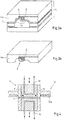
- FIG. 3a An optional embodiment of the forming tool is in the Fig. 3a ), b) shown in a perspective, schematic view.
- This in Fig. 3a ) shown forming tool 4 has an upper Umformtechnikmaschineschnet 4a, in which flow channels 5 are arranged, which produce a cooled portion 6 of the board, which is then formed at low temperature.
- a cooling medium for example liquid nitrogen or liquid oxygen or also cooled carbon dioxide flows through the flow channels and cools the board in this area from strong.
- the upper mold half 4a which has the flow channels and thus is particularly cold, even during the opening of the tool, the cooling medium through the flow channels leads.
- icing of the tool surfaces is prevented by training a protective gas atmosphere 8 in the region of the highly cooled surfaces of the forming tool takes place.
- Fig. 4 now an embodiment of a forming tool is shown, which has a closed circuit with respect to the cooling medium.
- the forming tool 9 shown schematically has coolant channels 10 in the region of the punch or the die, through which flows a correspondingly low-temperature cooling medium.
- the circuit board 1, which is arranged between the two halves of the forming tool 9 and having these surface contact, is very strongly cooled in the area of the contact surfaces with the cooled stamp and brought to forming temperature of less than -20 ° C. Should any areas be present that should not be brought to the appropriate temperature, means are provided in the stamp 11, which allow local heating of the board 1 in addition. These means may be configured, for example, as a heating cartridge or similar heat-emitting means.
- the mechanical deicing means 12 consist of a holder for receiving a scraper 12a, which cleans the surface of the punch 9 ', for example, when the forming tool 9 is opened. It is also conceivable to use brushes instead of the scraper 12a.
- the illustrated forming tool 9 can cool an inserted board 1 in a relatively short time due to the large surface contact on the forming temperature below -20 ° C and thus provide a simple, economical manufacturing process.
- FIGS. 5, 6 and 7 show typical embodiments of advantageous uses of the formed sheet metal part 1.
- the use of the sheet metal part as a B-pillar 13 of a motor vehicle 14 is shown schematically.
- the B-pillar 13 should preferably have a high yield strength and tensile strength roof connection area 13b and a lower strength but with a greater elongation at break equipped column foot 13a.
- this B-pillar can be produced in an economical manner by strongly cooling down the upper region of the B-pillar 13 in the forming tool and subsequently shaping it. This gives the upper region a significantly higher yield strength and tensile strength in comparison to the pedestal 13a.
- Fig. 6 shows two side members of a front portion of a vehicle body, which have two different functions in one component.
- the longitudinal members 17 serve, in the event of an impact, first to absorb the impact energy and to deform at least partially and, on the other hand, to protect the passenger compartment located in the rear region against further deformation.
- the longitudinal members 17 are usually designed such that the front region is easier to reshape and the rear region is formed as stiff as possible.
- a longitudinal member 17 can now be produced such that its front region 17a has a lower strength than the rear region 17b, wherein the rear region of the longitudinal member 17b is strongly cooled in the forming tool.
- FIG. 7 an example of an end wall 18, which is preferably produced by the method according to the invention.
- the end wall 18 is usually a large area and has a relatively small thickness.
- individual attachment regions 19 for example with a higher yield strength and tensile strength, so that no reinforcements in the form of patches, tailored blanks or separate components are more necessary.
- tailored blanks or separate components are more necessary.
- by targeted temperature control of the forming tool not only can be achieved that specific areas of the end wall 18 show a significantly different deformation behavior in the event of an impact, but also local areas are provided with corresponding yield strengths and tensile strengths, which are used to hold aggregates, such as Serve brake booster, air conditioning, etc., so that the end wall 18 can be designed load-appropriate without additional measures.
- Fig. 5 to 7 illustrated typical uses of the sheet metal part formed according to the invention can be provided in particular readily cathodic corrosion protection based on a zinc-containing surface coating and / or an organic surface coating, as can be dispensed with hot forming.
Landscapes
- Engineering & Computer Science (AREA)
- Mechanical Engineering (AREA)
- Shaping Metal By Deep-Drawing, Or The Like (AREA)
- Heat Treatment Of Articles (AREA)
- Body Structure For Vehicles (AREA)
- Heat Treatment Of Steel (AREA)
Description
- Die Erfindung betrifft ein Verfahren zur Herstellung eines umgeformten Blechteils aus einer Platine oder einem Halbzeug aus einem Werkstoff bestehend aus Stahl mit mindestens 60 Gew.-% Fe und einem Restaustenitgehalt von mindestens 5 %, bei welchem die Platine oder das Halbzeug vor dem Umformen zumindest teilweise auf eine Temperatur von weniger als -20 °C gekühlt wird und bei einer Temperatur unterhalb von -20 °C in einem Umformwerkzeug umgeformt wird. Daneben betrifft die Erfindung eine Vorrichtung zur Durchführung des Verfahrens sowie eine vorteilhafte Verwendung der hergestellten Blechteile.
- Um den zunehmenden Anforderungen zur Gewichtsersparnis, beispielsweise im Kraftfahrzeugbau gerecht zu werden, wurden Verfahren zur Herstellung von umgeformten Blechteilen entwickelt, welche insbesondere unter dem Begriff "Warmumformung" einen Presshärtvorgang durchlaufen, um maximale Festigkeiten, d.h. Streckgrenzen und Zugfestigkeiten im pressgehärteten Bauteil zu erzielen. Hiermit kann die Wanddicke des Blechteils und damit das Gewicht auf ein Minimum reduziert werden. Dabei muss die Platine oder das Halbzeug üblicherweise auf eine Temperatur oberhalb des AC1-Umwandlungstemperaturpunktes erhitzt werden, so dass im Wesentlichen austenitisches Gefüge im Blechteil vorliegt, um anschließend bei sehr hoher Temperatur umgeformt und schnell abgekühlt zu werden. Hierdurch wird erreicht, dass das austenitische Gefüge sich beim schnellen Abkühlen in Martensit umwandelt, so dass sehr hohe Zugfestigkeiten und Streckgrenzen bereitgestellt werden können. Mit Mangan-Bor-Stählen, beispielsweise einem Mangan-Bor-Stahl vom Typ MBW1500 können durch dieses Verfahren Zugfestigkeiten im Bereich von mehr als 1100 MPa bereitgestellt werden. Die bekannten Verfahren zur Warmumformung wurden darüber hinaus weiterentwickelt, so dass die Blechteile auch bereichsweise mit enormen Streckgrenzen und Zugfestigkeiten versehen werden können und so eine belastungsgerechte Auslegung der Blechteile erzielt werden kann. Die Verwendung eines "tailored Blanks", welches zusätzliche kostenintensive Arbeitsschritte in Form von einem Fügeschritt, beispielsweise unter Verwendung eines Laserstrahls benötigt, oder eines separaten Bauteils kann damit vermieden werden. Nachteilig bei der Warmumformung ist aber einerseits der enorme Energieaufwand, welcher zur Erwärmung der Platinen bzw. der Halbzeuge auf oberhalb der AC1-Umwandlungstemperatur, also meist oberhalb 850 °C, erforderlich ist. Darüber hinaus ergeben sich erhebliche Probleme mit Oberflächenbeschichtungen, welche beispielsweise zum Korrosionsschutz erforderlich sind. Konventionell werden feueraluminierte bzw. mit einer Al-Si-Beschichtung versehene Halbzeuge eingesetzt, besitzen jedoch keinen kathodischen Korrosionsschutz. Zinkhaltige Oberflächenbeschichtungen besitzen zwar einen kathodischen Korrosionsschutz, es besteht jedoch die Gefahr des Aufschmelzens des Zinks an der Oberfläche während der Erwärmung. Unbeschichtete Halbzeuge neigen zur Verzunderung, wenn nicht unter Schutzgas gearbeitet wird.
- Aus der japanischen Patentanmeldung
JP 2000/178640 A - Aufgabe der vorliegenden Erfindung ist es daher, ein Verfahren zur Herstellung von belastungsgerecht ausgelegten Bauteilen vorzuschlagen, welches einerseits einen großtechnischen Einsatz des Tieftemperaturumformens ermöglicht und besonders einfach ausgestaltet ist.
- Die oben aufgezeigte Aufgabe wird nach der ersten Lehre der vorliegenden Erfindung dadurch gelöst, dass eine Reduzierung der Werkstofftemperatur der Platine oder des Halbzeugs auf unter -20 °C in einer temperierten Kühleinrichtung erfolgt.
- Im Gegensatz zu dem bekannten Stand der Technik wird die Platine oder das Halbzeug in einer temperierten Kühleinrichtung auf Umformtemperatur unterhalb von -20 °C, vorzugsweise auf eine Temperatur im Bereich von -40 °C bis -180 °C temperiert. Die tiefen Temperaturen in Kombination mit einer Umformung bewirken bei dem verwendeten Restaustenitstahl der Platine oder des Halbzeugs eine teilweise Umwandlung des Austenits in Martensit, so dass eine erhebliche Steigerung, vor allem der Streckgrenze erzielt wird. Die temperierte Kühleinrichtung ermöglicht es zudem auf einfache Weise die Gefahr durch Verwendung von flüssigen, tiefgekühlten Kühlmedien wie beispielsweise flüssigem Sauerstoff, flüssigem Stickstoff oder auch von flüssigem oder festem Kohlendioxid (Trockeneis) erheblich zu verringern, so dass der großtechnische Einsatz der Tieftemperaturumformung ermöglicht wird. Als temperierte Kühleinrichtungen werden im Sinne der vorliegenden Patentanmeldung Vorrichtungen verstanden, in welchen die Platinen oder Halbzeuge positioniert und unter Verwendung von entsprechend kalten Kühlmedien auf Tieftemperatur gebracht werden. Hierzu ist es nicht zwingend erforderlich, dass die Platinen oder Halbzeuge in unmittelbarem Kontakt mit dem Kühlmedium, beispielsweise mit flüssigem Sauerstoff, Stickstoff oder Kohlendioxid stehen.
- Bevorzugt wird gemäß einer ersten Ausgestaltung der vorliegenden Erfindung die Platine oder das Halbzeug unmittelbar vor dem Umformprozess aus der Kühleinrichtung entnommen und dem Umformwerkzeug zugeführt. Durch die unmittelbare Entnahme der Platine oder des Halbzeugs vor dem Umformprozess wird ermöglicht, dass die Platine oder das Halbzeug möglichst noch auf Umformtemperatur bis zur Umformung gehalten werden kann und insofern auch zumindest zu Beginn des Umformprozesses die gewünschte Temperatur aufweist.
- Zusätzlich zur Verwendung der temperierten Kühleinrichtung besteht die Möglichkeit ein temperiertes Umformwerkzeug zu verwenden, so dass die aus der Kühleinrichtung entnommene Platine oder Halbzeug im Umformwerkzeug möglichst lange auf Tieftemperatur gehalten werden kann.
- Darüber hinaus ist es gemäß einer weiteren Ausgestaltung der vorliegenden Erfindung möglich als Kühleinrichtung das Umformwerkzeug selbst zu verwenden, in welchem die Platine oder das Halbzeug gekühlt und umgeformt wird. Das Umformwerkzeug weist hierzu Mittel zur Kühlung der Platine bzw. zur Temperierung der mit der Platine oder des Halbzeugs in Kontakt stehenden Bereiche auf, so dass ein optimaler Kühlprozess erreicht wird. Besonders vorteilhaft bei dieser Ausgestaltung des erfindungsgemäßen Verfahrens ist es, dass die Platine oder das Halbzeug lediglich in ein Umformwerkzeug eingebracht werden muss und in diesem ohne weitere Entnahme oder Transport umgeformt werden kann. Hierdurch wird eine maximale Prozesskontrolle erreicht, da die Umformtemperaturen auf einfache Weise über das Umformwerkzeug gesteuert werden können.
- Gemäß einer nächsten Ausgestaltung des erfindungsgemäßen Verfahrens temperiert das Umformwerkzeug die umzuformende Platine oder das umzuformende Halbzeug lediglich in den Bereichen, in denen eine hohe Streckgrenze und Zugfestigkeit gefordert wird. Hierdurch wird ermöglicht, dass allein durch die Ausgestaltung des Umformwerkzeugs die Bereiche des umgeformten Blechteils festgelegt werden, welche eine erhöhte Festigkeit, d.h. eine erhöhte Zugfestigkeit und/oder Streckgrenze aufgrund der Tieftemperaturumformung aufweisen soll.
- Da das Umformwerkzeug sehr niedrige Temperaturen aufweist, neigen die Flächen des Umformwerkzeugs bei Kontakt mit feuchter Außenluft zur Vereisung. Insofern kann gemäß einer weiteren Ausgestaltung des erfindungsgemäßen Verfahrens die Prozesssicherheit dadurch weiter gesteigert werden, dass die Vereisung des Umformwerkzeugs, der Platine und/oder des Halbzeugs unter Verwendung von Mitteln zur Enteisung vor und während der Umformungen verhindert wird.
- Wird die Vereisung unter Verwendung von mechanischen Enteisungsmitteln durchgeführt, kann eine bereits vorhandene Vereisung auf einfache Weise am Umformwerkzeug entfernt werden. Darüber hinaus besteht die Möglichkeit, dass zusätzlich oder alternativ durch Verwendung eines Schutzgases eine Schutzgasatmosphäre an den gekühlten Bereichen des Umformwerkzeugs, der Platine oder des Halbzeugs zu erzeugen so dass eine Vereisung verhindert wird. Durch die Bereitstellung einer Schutzgasatmosphäre an den gekühlten Bereichen der Platine oder des Umformwerkzeugs wird erreicht, dass keine Luftfeuchtigkeit an diesen Stellen auskondensieren bzw. ausfrieren kann und sich an den Bereichen der Platine, des Halbzeugs oder des Umformwerkzeugs niederschlägt. Diese Maßnahme kann beispielsweise mit mechanischen Enteisungsmitteln kombiniert werden.
- Bevorzugt erfolgt die Kühlung des Umformwerkzeugs, der Platine und/oder des Halbzeugs durch ein Schutzgas, wobei vorzugsweise das Schutzgas durch im Umformwerkzeug vorgesehene Strömungskanäle in die entsprechend zu kühlenden Bereiche des Umformwerkzeugs, der Platine und/oder des Halbzeugs strömt.
- Bei dem erfindungsgemäßen Verfahren können darüber hinaus besonders geringe Wanddicken der Platine oder des Halbzeugs eingesetzt werden. Diese betragen vorzugsweise 0,5 mm bis 1,80 mm, besonders bevorzugt 0,7 mm bis 1,20 mm. Insbesondere durch die Verwendung des temperierten Umformwerkzeugs ist eine entsprechende Umformung der Platine oder des Halbzeugs mit diesen geringen Dicken besonders vorteilhaft, da diese im Umformwerkzeug besonders schnell auf Tieftemperatur gebracht werden können und damit mit relativ geringer Zykluszeit belastungsgerechte, umgeformte Blechteile erzeugt werden können, welche an den höher belasteten Bereichen deutliche Festigkeitssteigerungen aufweisen.
- Besonders bevorzugt wird eine Platine oder ein Halbzeug umgeformt, welche bzw. welches eine Oberflächenbeschichtung aufweist, wobei als Oberflächenbeschichtung optional eine Zink enthaltende Oberflächenbeschichtung verwendet wird. Bei dem Tieftemperaturumformen wird die Oberflächenbeschichtung nicht beschädigt, so dass ohne Weiteres ein kathodischer Korrosionsschutz durch Verwendung einer Zink enthaltenden Oberflächenbeschichtung verwendet werden kann, ohne dass diese die Umformung negativ beeinflusst. Das so hergestellte Blechformteil weist einerseits belastungsgerechte Festigkeitswerte auf und ist darüber hinaus aufgrund der Oberflächenbeschichtung besonders gut vor Korrosion geschützt. Selbstverständlich kann neben einer Zink enthaltenden Oberflächenbeschichtung auch ohne Weiteres eine organische Beschichtung verwendet werden, welche bei den entsprechend niedrigen Temperaturen umformbar ist.
- Gemäß einem weiteren Aspekt wird die oben aufgezeigte Aufgabe durch eine Vorrichtung zur Durchführung des Verfahrens dadurch gelöst, dass ein Umformwerkzeug vorgesehen ist, welches eine Aufnahme zum Einlegen einer Platine oder eines Halbzeugs aufweist und Mittel zur zumindest bereichsweisen Kühlung der Platine oder des Halbzeugs auf eine Temperatur unterhalb von -20 °C in der Aufnahme vorgesehen sind. Die Vorrichtung ermöglicht es, die Platine oder das Halbzeug im Umformwerkzeug auf Umformtemperatur zu kühlen und ohne weiteren Transportschritt umzuformen. Hierdurch wird eine maximale Wirtschaftlichkeit dadurch erreicht, dass eine Entnahme der Platine oder des Halbzeugs zwischen dem Temperier- und Umformschritt aus dem Umformwerkzeug nicht mehr erfolgen muss.
- Bevorzugt weist das Umformwerkzeug Mittel zur Enteisung der gekühlten Bereiche des Umformwerkzeugs, der Platine und/oder des Halbzeugs auf, um einen dauerhaften, prozesssicheren Betrieb zu gewährleisten. Die Mittel können hierzu beispielsweise mechanische Mittel wie Bürsten oder Schaber umfassen, welche auch bereits vorhandene Vereisungen wieder entfernen können.
- Gemäß einer weiteren Ausgestaltung der Vorrichtung weist das Umformwerkzeug zumindest in den mit der Platine oder dem Halbzeug in Kontakt tretenden Bereichen Strömungskanäle auf, durch welche ein Kühlmedium zur lokalen Kühlung der Platine oder des Halbzeugs strömt. Als Kühlmedium wird vorzugsweise ein wasserfreies Kühlmedium, beispielsweise Trockeneis oder flüssiger Stickstoff verwendet. Beispielsweise können die Strömungskanäle bis zur Platine oder zum Halbzeug geführt werden, so dass diese die entsprechenden Bereiche der im Umformwerkzeug eingelegten Platine bzw. des eingelegten Halbzeugs auf niedrige Temperaturen kühlen und gleichzeitig ein Schutzgasatmosphäre gebildet wird, welche die Vereisung der Bereiche verhindert. Darüber hinaus können die Strömungskanäle aber auch nur im Umformwerkzeug verlaufen, so dass keine Kühlmedien, wie beispielsweise Sauerstoff, Stickstoff oder Kohlendioxid im bereich des Umformwerkzeugs austreten.
- Gemäß einer Ausgestaltung des Verfahrens wird die Platine oder das Halbzeug als Strukturteil eines Kraftfahrzeugs umgeformt, wobei das Strukturteil Bereiche mit unterschiedlichen Festigkeiten aufweist, gelöst. Wie bereits zuvor ausgeführt, besteht die Möglichkeit, durch das Tieftemperaturumformen ebenfalls große Festigkeitsunterschiede in umgeformten Blechteilen zu erzielen. Die Erhöhung der Streckgrenze und der Zugfestigkeit wird dabei aufgrund des Restaustenitgehaltes des Werkstoffes durch Umwandlung des Restaustenitgehaltes in matensitisches Gefüge erreicht. Durch die Wahl der Tieftemperatur kann eine Steigerung der Festigkeitserhöhung erreicht werden, wobei berücksichtigt werden muss, dass mit abnehmender Temperatur die Sprödigkeit des Werkstoffs zunimmt und damit die Umformgrade beschränkt sind.
- Da darüber hinaus, wie bereits ausgeführt, eine vor Korrosion schützende Oberflächenbeschichtung, insbesondere eine Zink enthaltende Beschichtung, in dem erfindungsgemäßen Verfahren keinen Schaden leidet, ist es besonders vorteilhaft, die Platine oder das Halbzeug als Säule, Träger, großflächiges Bauteil, Bodenblech, Tunnel, Stirnwand oder Radhaus eines Kraftfahrzeugs umzuformen. Alle genannten Blechteile sind üblicherweise einem mehr oder weniger starken Korrosionsangriff im Kraftfahrzeug ausgesetzt und erfordern daher eine vor Korrosion schützende Oberflächenbeschichtung. Darüber hinaus bieten belastungsgerecht ausgelegte, d.h. Bereiche mit unterschiedlichen Festigkeiten aufweisende Blechteile die Möglichkeit, Kosten einzusparen, da keine kostspieligeren tailored Blanks, welche aus mehreren Blechen bestehen, eingesetzt werden müssen. Die einstückigen Blechteile weisen auch keine die Festigkeit schwächende Schweißnaht auf. Ferner kann auch eine Bauteilreduktion und damit eine Kostenreduktion erzielt werden, da auf separate Verstärkungen verzichtet werden kann.
- Gemäß einer weiteren Ausgestaltung des erfindungsgemäßen Verfahrens wird die Platine oder das Halbzeug als A-, B-, C-Säule eines Kraftfahrzeugs umgeformt, wobei mindestens der Bereich der Dachanbindung der A-, B-, C-Säule eine höhere Festigkeit aufweist als der Bereich des Säulenfußes der A-, B-, C-Säule.
- Schließlich ergibt sich eine weitere vorteilhafte Ausgestaltung dadurch, dass die Platine oder das Halbzeug als Längsträger im Frontbereich eines Kraftfahrzeugs umgeformt wird und der Längsträger einen vorderen Bereich aufweist, welcher eine geringere Festigkeit als der hintere Bereich aufweist. Der vordere Bereich des Längsträgers im Frontbereich mit geringerer
Festigkeit soll im Falle eines Aufpralls sich verformen und insofern die Aufprallenergie absorbieren. Der hintere Bereich des Längsträgers soll dagegen nach Möglichkeit keiner Verformung unterliegen und somit den Fahrgastraum schützen. Entsprechende Lösungen konnten bisher lediglich durch Verwendung von Patches, tailored Blanks oder zusätzlichen Verstärkungsbauteilen realisiert werden. Das erfindungsgemäße Verfahren ermöglicht es zudem auf einfache Weise ein einstückiges Blechformteil bereitzustellen, welches neben einem sehr guten kathodischen Korrosionsschutz gleichzeitig auch eine vereinfachte und wirtschaftliche Herstellung eines Längsträgers mit Bereichen unterschiedlicher Festigkeiten ermöglicht. - Im Weiteren soll die Erfindung anhand von Ausführungsbeispielen in Verbindung mit der Zeichnung näher erläutert werden. Die Zeichnung zeigt in
- Fig. 1
- eine Prinzipskizze eines Ausführungsbeispiels des Verfahrens zur Herstellung eines umgeformten Blechteils,
- Fig. 2
- eine alternative Ausführungsform zu dem in
Fig. 1 dargestellten Verfahren, - Fig. 3a), b)
- ein Ausführungsbeispiel eines Umformwerkzeugs zur Durchführung des Verfahrens,
- Fig. 4
- ein weiteres Ausführungsbeispiel eines Umformwerkzeugs zur Durchführung des Verfahrens zur Herstellung eines umgeformten Blechteils und
- Fig. 5, 6 und 7
- Ausführungsbeispiele von vorteilhaften Verwendungen eines entsprechend hergestellten Blechteils.
- In
Fig. 1 ist zunächst eine Prinzipskizze des Verfahrens zur Herstellung eines umgeformten Blechteils dargestellt, bei welchem eine Platine 1 in einem Umformwerkzeug 2 umgeformt werden soll. Das Umformwerkzeug 2 ist als einfaches Tiefziehwerkzeug dargestellt. Das Umformwerkzeug 2 steht allerdings für beliebige Umformwerkzeuge, wie sie zur Erzeugung von umgeformten Blechteilen aus ebenen Platinen oder bereits vorgeformten oder zugeschnittenen Halbzeugen verwendet werden. Die Platine 1 besteht aus einem Stahl mit mindestens 60 Gew.-% Fe und einem Restaustenitgehalt von mindestens 5 %. Typische Vertreter dieser Stahlsorten sind beispielsweise hoch-manganhaltige Stähle aber auch TRIP-Stähle. Bei diesen Stählen insbesondere bei den Restaustenitstählen (TRIP-Stählen) wird beobachtet, dass bei einer Umformung austenitische Bereiche bei sehr tiefen Temperaturen sich teilweise in martensitisches Gefüge umwandeln und damit zusätzlich zur Verformungsfestigkeit eine weitere Streckgrenze und Festigkeitssteigerung erreicht wird. Es wurde festgestellt, dass dieser Effekt bei weiter sinkenden Temperaturen deutlich ansteigt, so dass der Verfestigungsvorgang, welcher zusätzlich zu dem klassischen Workhardening-Effekt noch einen sogenannten TRIP-Effekt darstellt, zu sehr hohen Streckgrenzen und Zugfestigkeiten führen kann. Beispielsweise kann mit einem RA-K 40/70 Stahl (TRIP-Stahl) die Streckgrenze von 410 MPa auf über 800 MPa gesteigert werden. In dem inFig. 1 dargestellten Ausführungsbeispiel des Verfahrens wird die Platine 1 zunächst in einer Kühleinrichtung 3 auf eine Temperatur von unterhalb von -20 °C, bevorzugt auf eine Temperatur von - 40 °C bis -190 °C abgekühlt. Hierzu können in der Kühleinrichtung Kühlmedien wie beispielsweise flüssiger Stickstoff, Trockeneis oder auch flüssiger Sauerstoff verwendet werden, ohne dass eine Sicherheitsgefährdung von Bedienpersonal der Vorrichtung erfolgt. Die temperierte Kühleinrichtung kann beispielsweise geschlossene Kreisläufe der entsprechend kalten Kühlmedien aufweisen, welche die Wärme beispielsweise über direkten Metallkontakt an die Platine oder das Halbzeug übertragen. Erreicht die Platine, welche eine Wanddicke von vorzugsweise 0,5 mm bis 1,8 mm, besonders bevorzugt 0,70 mm bis 1,20 mm aufweist, die Umformtemperatur wird diese kurz vor dem Umformvorgang aus der Kühleinrichtung 3 entnommen und dem Umformwerkzeug 2 zugeführt. Die Umformung erfolgt dann unmittelbar, so dass der Temperaturanstieg aufgrund der Entnahme aus der Kühleinrichtung begrenzt wird. Bevorzugt kann das Umformwerkzeug 2 selbst noch temperiert sein, so dass ein deutlicher Temperaturanstieg der Platine im Umformwerkzeug verhindert wird. - Wie aus
Fig. 1 zu erkennen ist, stellt die Kühleinrichtung 3 einen diskontinuierlichen Betrieb des Kühlens der Platine 1 zur Verfügung. Im Gegensatz dazu ermöglicht die inFig. 2 dargestellte Kühleinrichtung 3' einen kontinuierlichen Durchlauf der Platine 1 oder des Halbzeugs 1 durch die Kühleinrichtung 3', so dass die Platine 1 bzw. das Halbzeug 1 am Ausgang der Kühleinrichtung 3' auf Umformtemperatur gebracht wurde. Die Platine 1 bzw. das Halbzeug 1 wird dann unmittelbar nach dem Verlassen der Kühleinrichtung 3' in das Umformwerkzeug 2 eingelegt und umgeformt. Wie bereits zuvor ausgeführt, ist das Umformwerkzeug 2 hier lediglich stellvertretend als Tiefziehwerkzeug dargestellt. Grundsätzlich sind auch AHU/IHU-Umformwerkzeuge und beliebig andere Umformwerkzeuge denkbar, welche eine Umformung und damit eine Verfestigung im Blechteil hervorrufen, geeignet. - Eine optionale Ausgestaltung des Umformwerkzeugs ist in den
Fig. 3a ), b) in perspektivischer, schematischer Ansicht dargestellt. Das inFig. 3a ) dargestellte Umformwerkzeug 4 weist eine obere Umformwerkzeughälfte 4a auf, in welcher Strömungskanäle 5 angeordnet sind, welche einen gekühlten Bereich 6 der Platine erzeugen, welcher dann bei Tieftemperatur umgeformt wird. Hierzu strömt ein Kühlmedium, beispielsweise flüssiger Stickstoff oder flüssiger Sauerstoff oder auch tiefgekühltes Kohlendioxid durch die Strömungskanäle und kühlt dabei die Platine in diesen Bereich stark ab. - Beim Umformen erfolgt in den stark gekühlten Bereichen ein sehr viel stärkere Verfestigung durch den TRIP-Effekt als in nicht gekühlten Bereichen, so dass das hergestellte Blechteil 7 einen Bereich 7a aufweist, welcher aufgrund des starken TRIP-Effekts deutlich höhere Streckgrenzen und Zugfestigkeiten aufweist.
- Um die Vereisung des Umformwerkzeugs aus
Fig. 3a ) zu verhindern, ist es vorteilhaft, wenn beim Öffnen des Werkzeuges die obere Werkzeughälfte 4a, welche die Strömungskanäle aufweist und damit besonders kalt ist, auch während der Öffnung des Werkzeuges das Kühlmedium durch die Strömungskanäle führt. Hierdurch wird eine Vereisung der Werkzeugoberflächen dadurch verhindert, dass eine Ausbildung einer Schutzgasatmosphäre 8 im Bereich der stark gekühlten Oberflächen des Umformwerkzeugs erfolgt. - In
Fig. 4 ist nun ein Ausführungsbeispiel eines Umformwerkzeugs dargestellt, welches einen geschlossenen Kreislauf in Bezug auf das Kühlmedium aufweist. Das schematisch dargestellte Umformwerkzeug 9 weist hierzu im Bereich des Stempels bzw. der Matrize Kühlmittelkanäle 10 auf, durch welche ein entsprechend niedrig temperiertes Kühlmedium fließt. Die Platine 1, welche zwischen den beiden Hälften des Umformwerkzeugs 9 angeordnet ist und mit diesen flächigen Kontakt aufweist, wird im Bereich der Kontaktflächen mit dem gekühlten Stempel sehr stark abgekühlt und auf Umformtemperatur von weniger als -20 °C gebracht. Sollten eventuell Bereiche vorhanden sein, die nicht auf die entsprechende Temperatur gebracht werden sollen, sind Mittel im Stempel 11 vorgesehen, welche eine lokale Erwärmung der Platine 1 zusätzlich ermöglichen. Diese Mittel können beispielsweise als Heizpatrone oder ähnliche Wärme abgebende Mittel ausgestaltet sein. Darüber hinaus sind Mittel zur mechanischen Enteisung am Umformwerkzeug 9 vorgesehen und schematisch dargestellt. Die mechanischen Enteisungsmittel 12 bestehen aus einer Halterung zur Aufnahme eines Schabers 12a, welcher beispielsweise beim Öffnen des Umformwerkzeugs 9 die Oberfläche des Stempels 9' säubert. Denkbar ist auch der Einsatz von Bürsten anstelle des Schabers 12a. Das dargestellte Umformwerkzeug 9 kann jedenfalls eine eingelegte Platine 1 in relativ kurzer Zeit aufgrund des großen flächigen Kontakts auf die Umformtemperatur unterhalb von -20 °C abkühlen und damit einen einfachen, wirtschaftlichen Herstellprozess bereitstellen. - Die
Fig. 5, 6 und 7 zeigen typische Ausführungsbeispiele von vorteilhaften Verwendungen des umgeformten Blechteils 1. InFig. 5 ist beispielsweise die Verwendung des Blechteils als B-Säule 13 eines Kraftfahrzeugs 14 schematisch dargestellt. Die B-Säule 13 soll vorzugsweise einen mit hoher Streckgrenze und Zugfestigkeit ausgestatteten Dachanbindungsbereich 13b und einen mit geringerer Festigkeit dagegen mit einer größeren Bruchdehnung ausgestatteten Säulenfuß 13a aufweisen. Mit dem erfindungsgemäßen Verfahren kann diese B-Säule auf wirtschaftliche Weise hergestellt werden, indem der obere Bereich der B-Säule 13 im Umformwerkzeug stark runtergekühlt wird und anschließend umgeformt wird. Hierdurch erhält der obere Bereich eine deutlich höhere Streckgrenze und Zugfestigkeit im Vergleich zum Säulenfuß 13a. Gleiches gilt prinzipiell auch für die weiteren Säulen, die dargestellte A-Säule 15 und die C-Säule 16. -
Fig. 6 . zeigt zwei Längsträger eines Frontbereichs einer Fahrzeugkarosserie, welche zwei unterschiedliche Funktionen in einem Bauteil aufweisen. Die Längsträger 17 dienen einerseits dazu, im Falle eines Aufpralls zunächst die Aufprallenergie zu absorbieren und sich zumindest teilweise zu verformen und andererseits den im hinteren Bereich liegenden Fahrgastraum vor weiterer Verformung zu schützen. Hierzu sind die Längsträger 17 üblicherweise derart ausgestaltet, dass deren vorderer Bereich leichter umzuformen ist und der hintere Bereich möglichst steif ausgebildet ist. Mit dem erfindungsgemäßen Verfahren kann nun ein Längsträger 17 derart hergestellt werden, dass dessen vorderer Bereich 17a eine geringere Festigkeit als der hintere Bereich 17b aufweist, wobei im Umformwerkzeug der hintere Bereich des Längsträgers 17b stark gekühlt ist. Hierdurch wird erreicht, dass die Streckgrenze und Zugfestigkeiten der beiden Bereiche sich deutlich unterscheiden. So wird beispielsweise in dem mit hoher Streckgrenze versehenen Teil des Längsträgers 17, wie bei den anderen Verwendungen zuvor ebenfalls, eine Streckgrenze von mehr als 800 MPa bereitgestellt, so dass dieser Bereich besonders fest ausgebildet ist. Der Bereich 17a wird dagegen im gleichen Arbeitsgang weich ausgebildet, da dieser Bereich des Umformwerkzeugs nicht temperiert wird. Auf den Einsatz möglicher tailored Blanks, welche zusätzlich Arbeitsschritte benötigen, um ein ähnliches Festigkeitsprofil bereitzustellen, kann daher verzichtet werden. - Schließlich zeigt
Fig. 7 ein Beispiel einer Stirnwand 18, welches bevorzugt auch mit dem erfindungsgemäßen Verfahren hergestellt wird. Die Stirnwand 18 ist in der Regel großflächig und weist eine relativ geringe Dicke auf. Um nun möglichst einzelne Anbindungsbereiche 19 beispielsweise mit einer höheren Streckgrenze und Zugfestigkeit ausgebildet werden, so dass keine Verstärkungen in Form von Patches, tailored Blanks oder separaten Bauteilen mehr notwendig sind. Darüber hinaus kann durch gezielte Temperierung des Umformwerkzeugs nicht nur erreicht werden, dass spezifische Bereiche der Stirnwand 18 ein deutlich anderes Umformverhalten im Falle eines Aufpralls zeigen, sondern auch lokale Bereiche mit entsprechenden Streckgrenzen und Zugfestigkeiten bereit gestellt werden, die zur Aufnahmen von Aggregaten, wie beispielsweise Bremskraftverstärker, Klimaanlage etc. dienen, so dass die Stirnwand 18 ohne zusätzliche Maßnahmen belastungsgerecht ausgelegt werden kann. - Bei den in den
Fig. 5 bis 7 dargestellten typischen Verwendungen des erfindungsgemäß umgeformten Blechteils kann insbesondere ohne Weiteres ein kathodischer Korrosionsschutz basierend auf einer Zink enthaltenden Oberflächenbeschichtung und/oder einer organischen Oberflächenbeschichtung bereitgestellt werden, da auf eine Warmumformung verzichtet werden kann.
Claims (13)
- Verfahren zur Herstellung eines umgeformten Blechteils aus einer Platine (1) oder einem Halbzeug aus einem Werkstoff bestehend aus Stahl mit mindestens 60 Gew.-% Fe und einem Restaustenitgehalt von mindestens 5 %, dadurch gekennzeichnet, dass die Platine (1) oder das Halbzeug vor dem Umformen zumindest teilweise auf eine Temperatur von weniger als -20 °C gekühlt wird und bei einer Temperatur unterhalb von -20 °C in einem Umformwerkzeug umgeformt wird, wobei eine Reduzierung der Werkstofftemperatur der Platine oder des Halbzeugs auf unter -20 °C in einer temperierten Kühleinrichtung (3, 3') erfolgt.
- Verfahren nach Anspruch 1,
dadurch gekennzeichnet, dass die Platine (1) oder das Halbzeug unmittelbar vor dem Umformprozess aus der Kühleinrichtung (3, 3') entnommen und dem Umformwerkzeug (2, 4, 9) zugeführt werden. - Verfahren nach Anspruch 1,
dadurch gekennzeichnet, dass als Kühleinrichtung das Umformwerkzeug (2, 4, 9) verwendet wird, in welchem die Platine (1) oder das Halbzeug gekühlt und anschließend umgeformt wird. - Verfahren nach Anspruch 3,
dadurch gekennzeichnet, dass das Umformwerkzeug (2, 4, 9) die umzuformende Platine (1) oder das umzuformende Halbzeug lediglich in den Bereichen (6) temperiert, in welchen eine hohe Streckgrenze und Zugfestigkeit gefordert wird. - Verfahren nach Anspruch 3 oder 4,
dadurch gekennzeichnet, dass die Vereisung des Umformwerkzeugs (2, 4, 9), der Platine (1) und/oder des Halbzeugs unter Verwendung von Mitteln (8, 12) zur Enteisung vor und während der Umformung verhindert wird. - Verfahren nach einem der Ansprüche 3 bis 5,
dadurch gekennzeichnet, dass die Vereisung unter Verwendung von mechanischen Enteisungsmitteln (12) und/oder unter Verwendung eines Schutzgases zur Erzeugung einer Schutzgasatmosphäre (8) an den gekühlten Bereichen verhindert wird. - Verfahren nach einem der Ansprüche 3 bis 6,
dadurch gekennzeichnet, dass die Kühlung des Umformwerkzeugs (2, 4, 9), der Platine (1) und/oder des Halbzeugs durch ein Schutzgas erfolgt, wobei vorzugsweise das Schutzgas durch im Umformwerkzeug vorgesehene Strömungskanäle strömt. - Verfahren nach einem der Ansprüche 3 bis 7,
dadurch gekennzeichnet, dass die Wanddicke der Platine (1) oder des Halbzeugs 0,5 mm bis 1,80 mm, bevorzugt 0,7 mm bis 1,20 mm beträgt. - Verfahren nach Anspruch 1 bis 8,
dadurch gekennzeichnet, dass eine Platine (1) oder ein Halbzeug umgeformt wird, welche bzw. welches eine Oberflächenbeschichtung aufweist und als Oberflächenbeschichtung optional eine Zink enthaltende Oberflächenbeschichtung verwendet wird. - Verfahren nach einem der Ansprüche 1 bis 9
dadurch gekennzeichnet, dass die Platine (1) oder das Halbzeug als Strukturteil eines Kraftfahrzeugs, wobei das Strukturteil Bereiche mit unterschiedlichen Festigkeiten aufweist, umgeformt wird. - Verfahren nach Anspruch 10,
dadurch gekennzeichnet, dass die Platine (1) oder das Halbzeug als Säule (13, 14, 15), Träger (17), großflächiges Bauteil (18), Bodenblech, Tunnel, Stirnwand oder Radhaus eines Kraftfahrzeugs umgeformt wird. - Verfahren nach Anspruch 10 oder 11,
dadurch gekennzeichnet, dass die Platine (1) oder das Halbzeug als B-Säule (13) eines Kraftfahrzeugs umgeformt wird, wobei mindestens der Bereich der Dachanbindung (13b) der B-Säule eine höhere Festigkeit aufweist als der Bereich des B-Säulenfußes (13a). - Verfahren nach einem der Ansprüche 10 bis 12,
dadurch gekennzeichnet, dass die Platine (1) oder das Halbzeug als Längsträger (17) im Frontbereich eines Kraftfahrzeugs umgeformt wird und der Längsträger (17) einen vorderen Bereich (17a) aufweist, welcher eine geringere Festigkeit als der hintere Bereich (17b) aufweist.
Priority Applications (1)
| Application Number | Priority Date | Filing Date | Title |
|---|---|---|---|
| SI201330995T SI2855041T1 (en) | 2012-05-31 | 2013-05-28 | A process for the manufacture of preformed sheet metal parts at a low temperature |
Applications Claiming Priority (2)
| Application Number | Priority Date | Filing Date | Title |
|---|---|---|---|
| DE102012104734A DE102012104734A1 (de) | 2012-05-31 | 2012-05-31 | Verfahren und Vorrichtung zur Herstellung von umgeformten Blechteilen bei Tieftemperatur |
| PCT/EP2013/060934 WO2013178615A1 (de) | 2012-05-31 | 2013-05-28 | Verfahren und vorrichtung zur herstellung von umgeformten blechteilen bei tieftemperatur |
Publications (2)
| Publication Number | Publication Date |
|---|---|
| EP2855041A1 EP2855041A1 (de) | 2015-04-08 |
| EP2855041B1 true EP2855041B1 (de) | 2018-01-31 |
Family
ID=48539135
Family Applications (1)
| Application Number | Title | Priority Date | Filing Date |
|---|---|---|---|
| EP13726170.7A Not-in-force EP2855041B1 (de) | 2012-05-31 | 2013-05-28 | Verfahren zur herstellung von umgeformten blechteilen bei tieftemperatur |
Country Status (13)
| Country | Link |
|---|---|
| US (1) | US10532395B2 (de) |
| EP (1) | EP2855041B1 (de) |
| JP (1) | JP6068627B2 (de) |
| KR (1) | KR20150016319A (de) |
| CN (1) | CN104379272B (de) |
| BR (1) | BR112014030042A2 (de) |
| DE (1) | DE102012104734A1 (de) |
| ES (1) | ES2666312T3 (de) |
| IN (1) | IN2014MN02371A (de) |
| MX (1) | MX2014014544A (de) |
| SI (1) | SI2855041T1 (de) |
| WO (1) | WO2013178615A1 (de) |
| ZA (1) | ZA201409111B (de) |
Families Citing this family (17)
| Publication number | Priority date | Publication date | Assignee | Title |
|---|---|---|---|---|
| EP3020491A1 (de) * | 2014-11-14 | 2016-05-18 | Linde Aktiengesellschaft | Verfahren zum Umformen von Aluminiumblechen |
| DE102015203644A1 (de) * | 2015-03-02 | 2016-09-08 | Bayerische Motoren Werke Aktiengesellschaft | Pressgehärtetes Blechformteil mit unterschiedlichen Blechdicken und Festigkeiten |
| DE102016102344B4 (de) * | 2016-02-10 | 2020-09-24 | Voestalpine Metal Forming Gmbh | Verfahren und Vorrichtung zum Erzeugen gehärteter Stahlbauteile |
| US10619223B2 (en) | 2016-04-28 | 2020-04-14 | GM Global Technology Operations LLC | Zinc-coated hot formed steel component with tailored property |
| US10385415B2 (en) | 2016-04-28 | 2019-08-20 | GM Global Technology Operations LLC | Zinc-coated hot formed high strength steel part with through-thickness gradient microstructure |
| CN106140924A (zh) * | 2016-08-30 | 2016-11-23 | 山西北方机械制造有限责任公司 | 一种高强度厚钢板的引伸方法 |
| US20180221937A1 (en) * | 2017-02-06 | 2018-08-09 | Ross Casting And Innovation, Llc | Method and Apparatus For Producing A Forged Compressor Wheel |
| CN108326159B (zh) * | 2018-02-08 | 2020-03-17 | 苑世剑 | 一种大尺寸铝合金拼焊板类构件冷冻成形方法 |
| CN112513310A (zh) | 2018-05-24 | 2021-03-16 | 通用汽车环球科技运作有限责任公司 | 改善压制硬化钢的强度和延性的方法 |
| WO2019241902A1 (en) | 2018-06-19 | 2019-12-26 | GM Global Technology Operations LLC | Low density press-hardening steel having enhanced mechanical properties |
| JP2020146747A (ja) * | 2019-03-15 | 2020-09-17 | 本田技研工業株式会社 | 車体フレームの製造方法、及び車体フレーム |
| US11530469B2 (en) | 2019-07-02 | 2022-12-20 | GM Global Technology Operations LLC | Press hardened steel with surface layered homogenous oxide after hot forming |
| DE102020116126A1 (de) * | 2020-06-18 | 2021-12-23 | Bilstein Gmbh & Co. Kg | Verfahren zum Presshärten von warmumformbaren Platinen |
| CN112588931B (zh) * | 2020-11-26 | 2021-12-21 | 大连理工大学 | 一种复杂形状曲面件超低温介质压力成形方法 |
| CN112916700B (zh) * | 2021-02-05 | 2022-06-21 | 大连理工大学 | 一种大尺寸小特征曲面件局部超低温成形方法 |
| KR20240003795A (ko) * | 2022-07-01 | 2024-01-10 | 주식회사 엘지에너지솔루션 | 파우치 포밍 장치 및 이를 이용한 파우치 포밍 방법 |
| CN117548551B (zh) * | 2024-01-11 | 2024-03-26 | 湘潭大学 | 一种铝合金的成形方法 |
Family Cites Families (25)
| Publication number | Priority date | Publication date | Assignee | Title |
|---|---|---|---|---|
| US3469972A (en) * | 1966-01-04 | 1969-09-30 | Sandvikens Jernverks Ab | Razor blades and similar thin elongated sharp-edged blades made of a chromium steel |
| JPS5523884B2 (de) * | 1971-08-27 | 1980-06-25 | ||
| US3972744A (en) * | 1974-02-11 | 1976-08-03 | Houdaille Industries, Inc. | Method of and means for making lightweight, low cost impact resistant bumpers |
| JPS5540017A (en) * | 1978-09-08 | 1980-03-21 | Niigataken | Cooling and precision blanking method of stainless steel plate |
| JPH06154894A (ja) * | 1992-11-26 | 1994-06-03 | Kobe Steel Ltd | Al及びAl合金板の成形方法 |
| JPH08108233A (ja) * | 1994-10-07 | 1996-04-30 | Nissan Motor Co Ltd | 板材冷却搬送装置 |
| JP3287148B2 (ja) * | 1994-11-25 | 2002-05-27 | 日産自動車株式会社 | アルミニウム又はアルミニウム合金板のプレス加工方法及び装置並びに同加工方法に使用する恒温装置 |
| JP3975382B2 (ja) | 1998-12-21 | 2007-09-12 | 日産自動車株式会社 | プレス成形部品の製造方法 |
| CN2680680Y (zh) * | 2003-11-07 | 2005-02-23 | 钢铁研究总院 | 一种用于薄规格防弹钢板的压力淬火装置 |
| SE528130C2 (sv) * | 2004-10-04 | 2006-09-12 | Gestamp Hardtech Ab | Sätt att varmforma och härda ett plåtämne |
| ES2273589B1 (es) * | 2005-08-05 | 2008-04-16 | Mondragon Utillaje Y Sistemas, S.Coop. | Troquel con circuito de refrigeracion. |
| EP1767659A1 (de) * | 2005-09-21 | 2007-03-28 | ARCELOR France | Herstellungsverfahren eines Stahlwerkstücks mit mehrphasigem Mikrogefüge |
| JP4619262B2 (ja) * | 2005-10-24 | 2011-01-26 | 新日本製鐵株式会社 | 残留オーステナイト変態誘起塑性を有する高強度鋼鈑のプレス成形方法 |
| JP4760338B2 (ja) * | 2005-11-29 | 2011-08-31 | 日産自動車株式会社 | 低温成形加工における素材冷却方法、およびその装置 |
| JP4823718B2 (ja) * | 2006-03-02 | 2011-11-24 | 新日本製鐵株式会社 | 熱間成形金型及びプレス成形装置並びに熱間プレス成形方法 |
| DE102006019395A1 (de) * | 2006-04-24 | 2007-10-25 | Thyssenkrupp Steel Ag | Vorrichtung und Verfahren zum Umformen von Platinen aus höher- und höchstfesten Stählen |
| DE102008020794B4 (de) * | 2008-02-04 | 2018-03-29 | Volkswagen Ag | Verfahren zum Laserhärten von Stahlwerkstücken und dazugehörige Laserhärteanlage |
| US20090242086A1 (en) * | 2008-03-31 | 2009-10-01 | Honda Motor Co., Ltd. | Microstructural optimization of automotive structures |
| CN101280352B (zh) * | 2008-05-21 | 2010-06-09 | 钢铁研究总院 | 热成型马氏体钢零件制备方法 |
| EP2175041A1 (de) * | 2008-10-09 | 2010-04-14 | C.R.F. Società Consortile per Azioni | Verfahren zum Warmumformen von metallischen Platten |
| WO2010098256A1 (ja) * | 2009-02-24 | 2010-09-02 | 山形県 | マルテンサイト鋳鋼材及びマルテンサイト鋳鋼品の製造方法 |
| DE102009050623A1 (de) * | 2009-10-24 | 2010-05-20 | Daimler Ag | Verfahren und Vorrichtung zur Herstellung eines Stahlblechbauteiles |
| DE102011012240A1 (de) * | 2010-03-02 | 2011-11-03 | GM Global Technology Operations LLC | Fluid-assisted non-isothermal stamping of a sheet blank |
| DE102010012579B3 (de) * | 2010-03-23 | 2011-07-07 | Benteler Automobiltechnik GmbH, 33102 | Verfahren und Vorrichtung zur Herstellung von gehärteten Formbauteilen |
| DE102010020373A1 (de) * | 2010-05-12 | 2011-11-17 | Voestalpine Stahl Gmbh | Verfahren zur Herstellung eines Bauteils aus einem Eisen-Mangan-Stahlblech |
-
2012
- 2012-05-31 DE DE102012104734A patent/DE102012104734A1/de not_active Withdrawn
-
2013
- 2013-05-28 WO PCT/EP2013/060934 patent/WO2013178615A1/de not_active Ceased
- 2013-05-28 MX MX2014014544A patent/MX2014014544A/es unknown
- 2013-05-28 ES ES13726170.7T patent/ES2666312T3/es active Active
- 2013-05-28 SI SI201330995T patent/SI2855041T1/en unknown
- 2013-05-28 CN CN201380028507.1A patent/CN104379272B/zh not_active Expired - Fee Related
- 2013-05-28 JP JP2015514458A patent/JP6068627B2/ja not_active Expired - Fee Related
- 2013-05-28 IN IN2371MUN2014 patent/IN2014MN02371A/en unknown
- 2013-05-28 BR BR112014030042A patent/BR112014030042A2/pt not_active Application Discontinuation
- 2013-05-28 EP EP13726170.7A patent/EP2855041B1/de not_active Not-in-force
- 2013-05-28 KR KR1020147034450A patent/KR20150016319A/ko not_active Abandoned
-
2014
- 2014-11-26 US US14/554,206 patent/US10532395B2/en active Active
- 2014-12-11 ZA ZA2014/09111A patent/ZA201409111B/en unknown
Also Published As
| Publication number | Publication date |
|---|---|
| MX2014014544A (es) | 2015-09-04 |
| JP2015519205A (ja) | 2015-07-09 |
| SI2855041T1 (en) | 2018-06-29 |
| CN104379272A (zh) | 2015-02-25 |
| JP6068627B2 (ja) | 2017-01-25 |
| ZA201409111B (en) | 2017-09-27 |
| US20150082636A1 (en) | 2015-03-26 |
| DE102012104734A1 (de) | 2013-12-05 |
| US10532395B2 (en) | 2020-01-14 |
| EP2855041A1 (de) | 2015-04-08 |
| CN104379272B (zh) | 2017-03-15 |
| IN2014MN02371A (de) | 2015-08-14 |
| ES2666312T3 (es) | 2018-05-03 |
| WO2013178615A1 (de) | 2013-12-05 |
| BR112014030042A2 (pt) | 2019-09-03 |
| KR20150016319A (ko) | 2015-02-11 |
Similar Documents
| Publication | Publication Date | Title |
|---|---|---|
| EP2855041B1 (de) | Verfahren zur herstellung von umgeformten blechteilen bei tieftemperatur | |
| DE102010012830B4 (de) | Verfahren zur Herstellung einer Kraftfahrzeugkomponente und Karosseriebauteil | |
| DE10049660B4 (de) | Verfahren zum Herstellen lokal verstärkter Blechumformteile | |
| EP2473297B1 (de) | Verfahren und vorrichtung zur herstellung eines metallbauteils und verwendung eines solchen metallbauteils | |
| EP2496371B1 (de) | Verfahren zum herstellen von bauteilen mit bereichen unterschiedlicher duktilität | |
| EP2497840B2 (de) | Ofensystem zum partiellen Erwärmen von Stahlblechteilen | |
| EP2441851A1 (de) | Querträger sowie Verfahren zur Herstellung eines warmumgeformten und pressgehärteten Querträgers | |
| DE102009040935B4 (de) | Verfahren zum Herstellen von Bauteilen, insbesondere Karosseriebauteilen für ein Kraftfahrzeug, sowie Karosseriebauteil | |
| EP2028435A1 (de) | Panzerung für ein Fahrzeug | |
| DE102010049205B4 (de) | Warmumformlinie und Verfahren zum Warmumformen von blechförmigem Material | |
| EP2851138A1 (de) | Partiell gekühltes Warmformwerkzeug | |
| DE102004054795A1 (de) | Verfahren zur Herstellung von Blechbauteilen sowie Karosseriebauteil | |
| DE102014107210A1 (de) | Modulares Warmformwerkzeug | |
| EP2169084B1 (de) | Verfahren zur Herstellung eines Formbauteils mit Bereichen unterschiedlicher Festigkeit aus Kaltband | |
| EP3456456A1 (de) | Verfahren zur herstellung von tailor welded blanks (twbs) | |
| DE102007059974B3 (de) | Verfahren und Vorrichtung zur Herstellung von gehärteten Bauteilen aus Stahlblech, die ein geschlossenes Profil oder ein offenes Profil mit Hinterschnitt aufweisen | |
| EP3365469B1 (de) | Verfahren zum herstellen eines stahlbauteils für ein fahrzeug | |
| DE102006020623B4 (de) | Verfahren zum Herstellen von Bauteilen aus tailored blanks | |
| DE102013104299B4 (de) | Wirkmedienbasierte Tieftemperaturumformung | |
| DE102014213196A1 (de) | Formwerkzeug zur Herstellung von warmumgeformten Bauteilen | |
| WO2019048025A1 (de) | Verfahren zur herstellung eines bauteils und werkzeug dafür | |
| DE102011009891A1 (de) | Verfahren zum Herstellen von Blechbauteilen sowie Vorrichtung zur Durchführung des Verfahrens | |
| EP4296377A1 (de) | Verfahren zur herstellung eines einstückigen pressgehärteten türrings für ein kraftfahrzeug, der unterschiedliche blechdicken und festigkeiten aufweist | |
| DE102008043401B4 (de) | Verfahren und Vorrichtung zur Herstellung von Blechbauteilen mittels Warmumformung sowie dadurch hergestellte Blechbauteile | |
| EP3414072A1 (de) | Verfahren und vorrichtung zum erzeugen gehärteter stahlbauteile |
Legal Events
| Date | Code | Title | Description |
|---|---|---|---|
| PUAI | Public reference made under article 153(3) epc to a published international application that has entered the european phase |
Free format text: ORIGINAL CODE: 0009012 |
|
| 17P | Request for examination filed |
Effective date: 20141104 |
|
| AK | Designated contracting states |
Kind code of ref document: A1 Designated state(s): AL AT BE BG CH CY CZ DE DK EE ES FI FR GB GR HR HU IE IS IT LI LT LU LV MC MK MT NL NO PL PT RO RS SE SI SK SM TR |
|
| AX | Request for extension of the european patent |
Extension state: BA ME |
|
| DAX | Request for extension of the european patent (deleted) | ||
| 17Q | First examination report despatched |
Effective date: 20160311 |
|
| GRAP | Despatch of communication of intention to grant a patent |
Free format text: ORIGINAL CODE: EPIDOSNIGR1 |
|
| STAA | Information on the status of an ep patent application or granted ep patent |
Free format text: STATUS: GRANT OF PATENT IS INTENDED |
|
| RIC1 | Information provided on ipc code assigned before grant |
Ipc: B21D 37/16 20060101ALI20170309BHEP Ipc: B21D 22/02 20060101AFI20170309BHEP |
|
| INTG | Intention to grant announced |
Effective date: 20170411 |
|
| GRAS | Grant fee paid |
Free format text: ORIGINAL CODE: EPIDOSNIGR3 |
|
| RIN1 | Information on inventor provided before grant (corrected) |
Inventor name: ZOERNACK, MARKUS Inventor name: MOUSAVI RIZI, SEYED AMIN Inventor name: BOCHAROVA, EKATERINA Inventor name: HELLER, THOMAS Inventor name: GRUENEKLEE, AXEL |
|
| GRAA | (expected) grant |
Free format text: ORIGINAL CODE: 0009210 |
|
| STAA | Information on the status of an ep patent application or granted ep patent |
Free format text: STATUS: THE PATENT HAS BEEN GRANTED |
|
| RAP1 | Party data changed (applicant data changed or rights of an application transferred) |
Owner name: OUTOKUMPU NIROSTA GMBH Owner name: THYSSENKRUPP STEEL EUROPE AG |
|
| AK | Designated contracting states |
Kind code of ref document: B1 Designated state(s): AL AT BE BG CH CY CZ DE DK EE ES FI FR GB GR HR HU IE IS IT LI LT LU LV MC MK MT NL NO PL PT RO RS SE SI SK SM TR |
|
| REG | Reference to a national code |
Ref country code: GB Ref legal event code: FG4D Free format text: NOT ENGLISH Ref country code: CH Ref legal event code: EP |
|
| REG | Reference to a national code |
Ref country code: AT Ref legal event code: REF Ref document number: 966873 Country of ref document: AT Kind code of ref document: T Effective date: 20180215 |
|
| REG | Reference to a national code |
Ref country code: IE Ref legal event code: FG4D Free format text: LANGUAGE OF EP DOCUMENT: GERMAN |
|
| REG | Reference to a national code |
Ref country code: DE Ref legal event code: R096 Ref document number: 502013009342 Country of ref document: DE |
|
| REG | Reference to a national code |
Ref country code: NL Ref legal event code: FP |
|
| REG | Reference to a national code |
Ref country code: SE Ref legal event code: TRGR |
|
| REG | Reference to a national code |
Ref country code: ES Ref legal event code: FG2A Ref document number: 2666312 Country of ref document: ES Kind code of ref document: T3 Effective date: 20180503 |
|
| REG | Reference to a national code |
Ref country code: FR Ref legal event code: PLFP Year of fee payment: 6 |
|
| REG | Reference to a national code |
Ref country code: LT Ref legal event code: MG4D |
|
| PG25 | Lapsed in a contracting state [announced via postgrant information from national office to epo] |
Ref country code: LT Free format text: LAPSE BECAUSE OF FAILURE TO SUBMIT A TRANSLATION OF THE DESCRIPTION OR TO PAY THE FEE WITHIN THE PRESCRIBED TIME-LIMIT Effective date: 20180131 Ref country code: HR Free format text: LAPSE BECAUSE OF FAILURE TO SUBMIT A TRANSLATION OF THE DESCRIPTION OR TO PAY THE FEE WITHIN THE PRESCRIBED TIME-LIMIT Effective date: 20180131 Ref country code: NO Free format text: LAPSE BECAUSE OF FAILURE TO SUBMIT A TRANSLATION OF THE DESCRIPTION OR TO PAY THE FEE WITHIN THE PRESCRIBED TIME-LIMIT Effective date: 20180430 |
|
| PG25 | Lapsed in a contracting state [announced via postgrant information from national office to epo] |
Ref country code: RS Free format text: LAPSE BECAUSE OF FAILURE TO SUBMIT A TRANSLATION OF THE DESCRIPTION OR TO PAY THE FEE WITHIN THE PRESCRIBED TIME-LIMIT Effective date: 20180131 Ref country code: PL Free format text: LAPSE BECAUSE OF FAILURE TO SUBMIT A TRANSLATION OF THE DESCRIPTION OR TO PAY THE FEE WITHIN THE PRESCRIBED TIME-LIMIT Effective date: 20180131 Ref country code: IS Free format text: LAPSE BECAUSE OF FAILURE TO SUBMIT A TRANSLATION OF THE DESCRIPTION OR TO PAY THE FEE WITHIN THE PRESCRIBED TIME-LIMIT Effective date: 20180531 Ref country code: BG Free format text: LAPSE BECAUSE OF FAILURE TO SUBMIT A TRANSLATION OF THE DESCRIPTION OR TO PAY THE FEE WITHIN THE PRESCRIBED TIME-LIMIT Effective date: 20180430 Ref country code: LV Free format text: LAPSE BECAUSE OF FAILURE TO SUBMIT A TRANSLATION OF THE DESCRIPTION OR TO PAY THE FEE WITHIN THE PRESCRIBED TIME-LIMIT Effective date: 20180131 |
|
| REG | Reference to a national code |
Ref country code: GR Ref legal event code: EP Ref document number: 20180401090 Country of ref document: GR Effective date: 20180829 |
|
| PG25 | Lapsed in a contracting state [announced via postgrant information from national office to epo] |
Ref country code: MT Free format text: LAPSE BECAUSE OF FAILURE TO SUBMIT A TRANSLATION OF THE DESCRIPTION OR TO PAY THE FEE WITHIN THE PRESCRIBED TIME-LIMIT Effective date: 20180131 |
|
| PG25 | Lapsed in a contracting state [announced via postgrant information from national office to epo] |
Ref country code: AL Free format text: LAPSE BECAUSE OF FAILURE TO SUBMIT A TRANSLATION OF THE DESCRIPTION OR TO PAY THE FEE WITHIN THE PRESCRIBED TIME-LIMIT Effective date: 20180131 Ref country code: RO Free format text: LAPSE BECAUSE OF FAILURE TO SUBMIT A TRANSLATION OF THE DESCRIPTION OR TO PAY THE FEE WITHIN THE PRESCRIBED TIME-LIMIT Effective date: 20180131 Ref country code: EE Free format text: LAPSE BECAUSE OF FAILURE TO SUBMIT A TRANSLATION OF THE DESCRIPTION OR TO PAY THE FEE WITHIN THE PRESCRIBED TIME-LIMIT Effective date: 20180131 |
|
| REG | Reference to a national code |
Ref country code: DE Ref legal event code: R097 Ref document number: 502013009342 Country of ref document: DE |
|
| PG25 | Lapsed in a contracting state [announced via postgrant information from national office to epo] |
Ref country code: SK Free format text: LAPSE BECAUSE OF FAILURE TO SUBMIT A TRANSLATION OF THE DESCRIPTION OR TO PAY THE FEE WITHIN THE PRESCRIBED TIME-LIMIT Effective date: 20180131 Ref country code: CZ Free format text: LAPSE BECAUSE OF FAILURE TO SUBMIT A TRANSLATION OF THE DESCRIPTION OR TO PAY THE FEE WITHIN THE PRESCRIBED TIME-LIMIT Effective date: 20180131 Ref country code: SM Free format text: LAPSE BECAUSE OF FAILURE TO SUBMIT A TRANSLATION OF THE DESCRIPTION OR TO PAY THE FEE WITHIN THE PRESCRIBED TIME-LIMIT Effective date: 20180131 Ref country code: DK Free format text: LAPSE BECAUSE OF FAILURE TO SUBMIT A TRANSLATION OF THE DESCRIPTION OR TO PAY THE FEE WITHIN THE PRESCRIBED TIME-LIMIT Effective date: 20180131 |
|
| PLBE | No opposition filed within time limit |
Free format text: ORIGINAL CODE: 0009261 |
|
| STAA | Information on the status of an ep patent application or granted ep patent |
Free format text: STATUS: NO OPPOSITION FILED WITHIN TIME LIMIT |
|
| REG | Reference to a national code |
Ref country code: CH Ref legal event code: PL |
|
| 26N | No opposition filed |
Effective date: 20181102 |
|
| PG25 | Lapsed in a contracting state [announced via postgrant information from national office to epo] |
Ref country code: MC Free format text: LAPSE BECAUSE OF FAILURE TO SUBMIT A TRANSLATION OF THE DESCRIPTION OR TO PAY THE FEE WITHIN THE PRESCRIBED TIME-LIMIT Effective date: 20180131 |
|
| REG | Reference to a national code |
Ref country code: IE Ref legal event code: MM4A |
|
| PG25 | Lapsed in a contracting state [announced via postgrant information from national office to epo] |
Ref country code: CH Free format text: LAPSE BECAUSE OF NON-PAYMENT OF DUE FEES Effective date: 20180531 Ref country code: LI Free format text: LAPSE BECAUSE OF NON-PAYMENT OF DUE FEES Effective date: 20180531 |
|
| PG25 | Lapsed in a contracting state [announced via postgrant information from national office to epo] |
Ref country code: LU Free format text: LAPSE BECAUSE OF NON-PAYMENT OF DUE FEES Effective date: 20180528 |
|
| PG25 | Lapsed in a contracting state [announced via postgrant information from national office to epo] |
Ref country code: IE Free format text: LAPSE BECAUSE OF NON-PAYMENT OF DUE FEES Effective date: 20180528 |
|
| PGFP | Annual fee paid to national office [announced via postgrant information from national office to epo] |
Ref country code: GR Payment date: 20190430 Year of fee payment: 7 Ref country code: SI Payment date: 20190514 Year of fee payment: 7 |
|
| PG25 | Lapsed in a contracting state [announced via postgrant information from national office to epo] |
Ref country code: PT Free format text: LAPSE BECAUSE OF FAILURE TO SUBMIT A TRANSLATION OF THE DESCRIPTION OR TO PAY THE FEE WITHIN THE PRESCRIBED TIME-LIMIT Effective date: 20180131 |
|
| PG25 | Lapsed in a contracting state [announced via postgrant information from national office to epo] |
Ref country code: CY Free format text: LAPSE BECAUSE OF FAILURE TO SUBMIT A TRANSLATION OF THE DESCRIPTION OR TO PAY THE FEE WITHIN THE PRESCRIBED TIME-LIMIT Effective date: 20180131 Ref country code: HU Free format text: LAPSE BECAUSE OF FAILURE TO SUBMIT A TRANSLATION OF THE DESCRIPTION OR TO PAY THE FEE WITHIN THE PRESCRIBED TIME-LIMIT; INVALID AB INITIO Effective date: 20130528 Ref country code: MK Free format text: LAPSE BECAUSE OF NON-PAYMENT OF DUE FEES Effective date: 20180131 |
|
| PGFP | Annual fee paid to national office [announced via postgrant information from national office to epo] |
Ref country code: ES Payment date: 20200619 Year of fee payment: 8 Ref country code: NL Payment date: 20200520 Year of fee payment: 8 Ref country code: DE Payment date: 20200519 Year of fee payment: 8 Ref country code: FI Payment date: 20200520 Year of fee payment: 8 Ref country code: FR Payment date: 20200519 Year of fee payment: 8 |
|
| PGFP | Annual fee paid to national office [announced via postgrant information from national office to epo] |
Ref country code: BE Payment date: 20200520 Year of fee payment: 8 Ref country code: SE Payment date: 20200519 Year of fee payment: 8 Ref country code: GB Payment date: 20200518 Year of fee payment: 8 Ref country code: IT Payment date: 20200522 Year of fee payment: 8 |
|
| PGFP | Annual fee paid to national office [announced via postgrant information from national office to epo] |
Ref country code: AT Payment date: 20200520 Year of fee payment: 8 |
|
| PG25 | Lapsed in a contracting state [announced via postgrant information from national office to epo] |
Ref country code: GR Free format text: LAPSE BECAUSE OF NON-PAYMENT OF DUE FEES Effective date: 20201209 |
|
| REG | Reference to a national code |
Ref country code: SI Ref legal event code: KO00 Effective date: 20210317 |
|
| PG25 | Lapsed in a contracting state [announced via postgrant information from national office to epo] |
Ref country code: SI Free format text: LAPSE BECAUSE OF NON-PAYMENT OF DUE FEES Effective date: 20200529 |
|
| REG | Reference to a national code |
Ref country code: DE Ref legal event code: R119 Ref document number: 502013009342 Country of ref document: DE |
|
| REG | Reference to a national code |
Ref country code: FI Ref legal event code: MAE |
|
| REG | Reference to a national code |
Ref country code: SE Ref legal event code: EUG |
|
| REG | Reference to a national code |
Ref country code: NL Ref legal event code: MM Effective date: 20210601 |
|
| REG | Reference to a national code |
Ref country code: AT Ref legal event code: MM01 Ref document number: 966873 Country of ref document: AT Kind code of ref document: T Effective date: 20210528 |
|
| GBPC | Gb: european patent ceased through non-payment of renewal fee |
Effective date: 20210528 |
|
| PG25 | Lapsed in a contracting state [announced via postgrant information from national office to epo] |
Ref country code: SE Free format text: LAPSE BECAUSE OF NON-PAYMENT OF DUE FEES Effective date: 20210529 Ref country code: AT Free format text: LAPSE BECAUSE OF NON-PAYMENT OF DUE FEES Effective date: 20210528 Ref country code: FI Free format text: LAPSE BECAUSE OF NON-PAYMENT OF DUE FEES Effective date: 20210528 |
|
| REG | Reference to a national code |
Ref country code: BE Ref legal event code: MM Effective date: 20210531 |
|
| PG25 | Lapsed in a contracting state [announced via postgrant information from national office to epo] |
Ref country code: GB Free format text: LAPSE BECAUSE OF NON-PAYMENT OF DUE FEES Effective date: 20210528 Ref country code: DE Free format text: LAPSE BECAUSE OF NON-PAYMENT OF DUE FEES Effective date: 20211201 |
|
| PG25 | Lapsed in a contracting state [announced via postgrant information from national office to epo] |
Ref country code: NL Free format text: LAPSE BECAUSE OF NON-PAYMENT OF DUE FEES Effective date: 20210601 Ref country code: FR Free format text: LAPSE BECAUSE OF NON-PAYMENT OF DUE FEES Effective date: 20210531 |
|
| PG25 | Lapsed in a contracting state [announced via postgrant information from national office to epo] |
Ref country code: TR Free format text: LAPSE BECAUSE OF NON-PAYMENT OF DUE FEES Effective date: 20200528 |
|
| PG25 | Lapsed in a contracting state [announced via postgrant information from national office to epo] |
Ref country code: BE Free format text: LAPSE BECAUSE OF NON-PAYMENT OF DUE FEES Effective date: 20210531 |
|
| REG | Reference to a national code |
Ref country code: ES Ref legal event code: FD2A Effective date: 20220829 |
|
| PG25 | Lapsed in a contracting state [announced via postgrant information from national office to epo] |
Ref country code: ES Free format text: LAPSE BECAUSE OF NON-PAYMENT OF DUE FEES Effective date: 20210529 |
|
| PG25 | Lapsed in a contracting state [announced via postgrant information from national office to epo] |
Ref country code: IT Free format text: LAPSE BECAUSE OF NON-PAYMENT OF DUE FEES Effective date: 20200528 |
|
| PG25 | Lapsed in a contracting state [announced via postgrant information from national office to epo] |
Ref country code: IT Free format text: LAPSE BECAUSE OF NON-PAYMENT OF DUE FEES Effective date: 20210528 |