EP2853414B1 - Deformierbare radeinheit - Google Patents
Deformierbare radeinheit Download PDFInfo
- Publication number
- EP2853414B1 EP2853414B1 EP14188573.1A EP14188573A EP2853414B1 EP 2853414 B1 EP2853414 B1 EP 2853414B1 EP 14188573 A EP14188573 A EP 14188573A EP 2853414 B1 EP2853414 B1 EP 2853414B1
- Authority
- EP
- European Patent Office
- Prior art keywords
- frustum
- conical
- locomotion assembly
- ground
- engaging member
- Prior art date
- Legal status (The legal status is an assumption and is not a legal conclusion. Google has not performed a legal analysis and makes no representation as to the accuracy of the status listed.)
- Active
Links
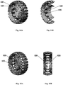
Images


Classifications
-
- B—PERFORMING OPERATIONS; TRANSPORTING
- B60—VEHICLES IN GENERAL
- B60B—VEHICLE WHEELS; CASTORS; AXLES FOR WHEELS OR CASTORS; INCREASING WHEEL ADHESION
- B60B9/00—Wheels of high resiliency, e.g. with conical interacting pressure-surfaces
- B60B9/02—Wheels of high resiliency, e.g. with conical interacting pressure-surfaces using springs resiliently mounted bicycle rims
- B60B9/10—Wheels of high resiliency, e.g. with conical interacting pressure-surfaces using springs resiliently mounted bicycle rims of rubber or the like
-
- B—PERFORMING OPERATIONS; TRANSPORTING
- B60—VEHICLES IN GENERAL
- B60B—VEHICLE WHEELS; CASTORS; AXLES FOR WHEELS OR CASTORS; INCREASING WHEEL ADHESION
- B60B9/00—Wheels of high resiliency, e.g. with conical interacting pressure-surfaces
-
- B—PERFORMING OPERATIONS; TRANSPORTING
- B60—VEHICLES IN GENERAL
- B60B—VEHICLE WHEELS; CASTORS; AXLES FOR WHEELS OR CASTORS; INCREASING WHEEL ADHESION
- B60B19/00—Wheels not otherwise provided for or having characteristics specified in one of the subgroups of this group
-
- B—PERFORMING OPERATIONS; TRANSPORTING
- B60—VEHICLES IN GENERAL
- B60B—VEHICLE WHEELS; CASTORS; AXLES FOR WHEELS OR CASTORS; INCREASING WHEEL ADHESION
- B60B3/00—Disc wheels, i.e. wheels with load-supporting disc body
-
- B—PERFORMING OPERATIONS; TRANSPORTING
- B60—VEHICLES IN GENERAL
- B60C—VEHICLE TYRES; TYRE INFLATION; TYRE CHANGING; CONNECTING VALVES TO INFLATABLE ELASTIC BODIES IN GENERAL; DEVICES OR ARRANGEMENTS RELATED TO TYRES
- B60C7/00—Non-inflatable or solid tyres
- B60C7/10—Non-inflatable or solid tyres characterised by means for increasing resiliency
- B60C7/14—Non-inflatable or solid tyres characterised by means for increasing resiliency using springs
-
- B—PERFORMING OPERATIONS; TRANSPORTING
- B60—VEHICLES IN GENERAL
- B60B—VEHICLE WHEELS; CASTORS; AXLES FOR WHEELS OR CASTORS; INCREASING WHEEL ADHESION
- B60B2310/00—Manufacturing methods
- B60B2310/30—Manufacturing methods joining
- B60B2310/302—Manufacturing methods joining by welding
-
- B—PERFORMING OPERATIONS; TRANSPORTING
- B60—VEHICLES IN GENERAL
- B60B—VEHICLE WHEELS; CASTORS; AXLES FOR WHEELS OR CASTORS; INCREASING WHEEL ADHESION
- B60B2310/00—Manufacturing methods
- B60B2310/30—Manufacturing methods joining
- B60B2310/305—Manufacturing methods joining by screwing
-
- B—PERFORMING OPERATIONS; TRANSPORTING
- B60—VEHICLES IN GENERAL
- B60B—VEHICLE WHEELS; CASTORS; AXLES FOR WHEELS OR CASTORS; INCREASING WHEEL ADHESION
- B60B2310/00—Manufacturing methods
- B60B2310/30—Manufacturing methods joining
- B60B2310/314—Manufacturing methods joining by deformation
-
- B—PERFORMING OPERATIONS; TRANSPORTING
- B60—VEHICLES IN GENERAL
- B60B—VEHICLE WHEELS; CASTORS; AXLES FOR WHEELS OR CASTORS; INCREASING WHEEL ADHESION
- B60B2310/00—Manufacturing methods
- B60B2310/30—Manufacturing methods joining
- B60B2310/316—Manufacturing methods joining by press-fitting, shrink-fitting
-
- B—PERFORMING OPERATIONS; TRANSPORTING
- B60—VEHICLES IN GENERAL
- B60B—VEHICLE WHEELS; CASTORS; AXLES FOR WHEELS OR CASTORS; INCREASING WHEEL ADHESION
- B60B2360/00—Materials; Physical forms thereof
- B60B2360/10—Metallic materials
-
- B—PERFORMING OPERATIONS; TRANSPORTING
- B60—VEHICLES IN GENERAL
- B60B—VEHICLE WHEELS; CASTORS; AXLES FOR WHEELS OR CASTORS; INCREASING WHEEL ADHESION
- B60B2360/00—Materials; Physical forms thereof
- B60B2360/30—Synthetic materials
- B60B2360/32—Plastic compositions
-
- B—PERFORMING OPERATIONS; TRANSPORTING
- B60—VEHICLES IN GENERAL
- B60B—VEHICLE WHEELS; CASTORS; AXLES FOR WHEELS OR CASTORS; INCREASING WHEEL ADHESION
- B60B2360/00—Materials; Physical forms thereof
- B60B2360/50—Rubbers
-
- B—PERFORMING OPERATIONS; TRANSPORTING
- B60—VEHICLES IN GENERAL
- B60Y—INDEXING SCHEME RELATING TO ASPECTS CROSS-CUTTING VEHICLE TECHNOLOGY
- B60Y2200/00—Type of vehicle
- B60Y2200/20—Off-Road Vehicles
- B60Y2200/22—Agricultural vehicles
- B60Y2200/221—Tractors
Definitions
- This invention relates to a locomotion assembly, in particularly a locomotion assembly for a vehicle, of the kind that can assume a rounded, wheel-like configuration and a more flattened, belt like configuration.
- Locomotion assemblies that comprise members that can assume a wheel-like configuration, on the one hand, and a caterpillar-like configuration, on the other hand are known. Some examples of such assemblies are described in US patents 3,698,461 , 6,422,576 , 7,334,850 , 7,557,078 ; and are also described in US patents 7,334,850 and 7,547,078 , both assigned to the assignee of the present application.
- Document DE 66 733 discloses a wheel for bicycles and vehicles of all kinds, the crown of which, for the purpose of increasing elasticity, is made of a plurality of flexible tires joined together by interposed blocks of elastic material. This composite elastic tire is fixed to the fixed tire or wheel rim of the wheel by means of lacing with tapes of canvas or the like.
- the present invention provides a novel locomotion assembly which can be used for propelling a surface vehicle.
- the locomotion assembly comprises at least one, or preferably a pair of flexible members, each having a frustum-conical surface extending between its relatively narrow and wide ends along a frustum-conical axis.
- a frustum-conically shaped configuration has a flat pattern projection (2D projection), i.e. the surface of said frustum-conical member can be opened/unfolded into a planar topology.
- 2D projection the surface of said frustum-conical member can be opened/unfolded into a planar topology.
- a frustum-conical geometry is known as that defining a frustum-conical surface extending between relatively large and small circular bases on parallel planes, thus defining a frustum-conical axis.
- a shape having no flat 2D projection provides higher rigidity on the cost of flexibility, and vice versa for a shape having a flat 2D projection such as a frustum-conical shape.
- a force of a given profile applied to a pure cone-shape body and a conoid-shape body would cause significantly high stress at different points at the conoid-shape body than at the pure cone body, thus periodic application of stress (as typically happens when rolling as a wheel of a vehicle for example) would result in significantly higher material fatigue and heat buildup in the conoid-shape body, as may.
- the frustum-conical member used in the locomotion assembly of the present invention is flexible such that it is reversibly deformable from its biased rounded shape (being true frustum-conical one) in which its side elevation is circular into a more flattened shape (deformed frustum-conical shape) in which its side elevation is non-circular.
- the frustum-conical member however is rigid in the meaning that it is non-extendable in its circumferential dimension.
- the frustum-conical member is made of non-stretchable flexible sheet.
- the paired frustum-conical members are rotatable about a common axis coinciding with their frustum-conical axes, and arranged in a substantially symmetric manner.
- a "substantially symmetric arrangement" of the frustum-conical members should be interpreted broader than bilateral or mirror symmetry.
- the paired frustum-conical members are referred to as "substantially symmetrically identical” or as arranged in a “substantially symmetric” fashion, in the meaning that they are oppositely oriented with a common axis (they face each other either by their wide ends or by their narrow ends), and they are either identical or have similar geometry, i.e.
- the frustum-conical members of a pair have equal conical angles, and may for example have equal geometry (dimensions) at their wide ends, and the same or different heights (i.e. lengths along their axes) and accordingly the same or different geometry (dimensions) at their narrow ends.
- the frustum-conical member may be formed by a single element having a frustum-conical surface or by multiple elements defining together said frustum-conical surface.
- the frustum-conical members of a pair are assembled inversely (oppositely oriented), and forces of any type (e.g. driving forces) applied to the surface of one such member to roll in a radius around its geometric vertex are balanced by the same forces applied from the opposite member, resulting in that an assembly formed by such pair of inverted frustum-conical members rolls in a straight line (i.e. perpendicular to the frustum-conical axis).
- forces of any type e.g. driving forces
- the two frustum-conical members of a pair may be arranged in different ways, provided the two members are concentrically arranged and oppositely oriented. In some examples, they are arranged in a spaced-apart relationship along the common axis, for example, such that their narrower or wider bases are coinciding (as a 'back' to 'back' or 'face' to 'face' arrangement).
- each of the frustum-conical members includes a patterned portion of its frustum-conical surface formed by an array of slits (receptacles, grooves, cavities or bores) spaced by rigid spikes along its circumference at the side by which it faces the other member, thus formatting a grid and enabling one frustum-conical member to engage with (penetrates into) the other in conjunction, so there is no contact between the walls of the frustum-conical members.
- two frustum-conical members are configured such that each of them is divided into two parts in manner that there is no such region where segments of one frustum-conical member pass into the other frustum-conical member, but rather a small part of one member is coupled in a partial flexible manner to a larger part of the other oppositely oriented member.
- the configuration of a structure formed by a pair of frustum-conical members is such that an external circumferential part of the structure executes coupling between the two oppositely oriented frustum-conical members, via their common axis.
- the frustum-conical structure formed by at least one or preferably by a pair of the above-described frustum-conical members may serve as a support structure for supporting at least one surface-engaging member of the locomotion assembly.
- the surface-engaging member is convertible between a round wheel-like configuration, in which its side elevation is substantially circular, and a deformed configuration, in which its side elevation is non-circular and in which a larger portion of the surface-engaging member is in contact with the surface of movement (e.g. ground).
- ground a surface of movement
- the invention is limited neither to a ground movement of a locomotion assembly nor to a movement along any solid surface.
- the surface-engaging member has typically an outer surface by which it contacts the surface of movement, such that in the deformed state of the surface-engaging member, said outer surface thereof maintains the substantially parallel orientation with respect to the surface of movement.
- each of the frustum-conical members may be is coupled to the surface-engaging member, such that the paired support members are coupled to the same surface-engaging member or two different surface-engaging members.
- the arrangement is such that a bias of each of the frustum-conical members of a pair to move in a non-linear direction (and thus induce the surface engaging member to move in a non-linear direction) is offset by the other frustum-conical member of the pair.
- a wheel may comprise an inflatable rubber tire defining an enclosed fluid-pressure holding space with a circumferential surface-engaging member; and a support structure integrally formed in the wheel and comprising the above-described frustum-conical structure formed by at least one pair of oppositely oriented frustum-conical support members of equal conical angles, each defining a frustum-conical surface extending between relatively narrow and wide ends of the support member along a frustum-conical axis, each of the support members being coupled at the wide end of the frustum-conical surface to one side of the surface-engaging member opposite that of the other, each support member being made from a rigid material and being flexible and biased into rounded shape in which its side elevation is circular and being reversibly deformable into a more flatt
- the frustum-conical structure of the invention formed by at least one or preferably at least one pair of frustum-conical support members, links the surface-engaging member(s) and a vehicle's axle, transferring a force from the vehicle's axle to the surface-engaging member.
- the flexible support members are reversibly deformable from their natural, frustum-conical shape (in which they have a substantially circular cross-sectional shape) into a deformed, somewhat flattened shape in tandem with the conversion of the surface-engaging member(s) from the round configuration to the deformed non-circular configuration.
- said linking support structure can translate or link between a circular motion at the axle to a non-circular, caterpillar-like motion of the surface-engaging member in which a segment thereof is in contact with the surface of movement (e.g. ground).
- a locomotion assembly for a vehicle that comprises a flexible surface-engaging member and a flexible support structure.
- the flexible surface-engaging member has wheel-like, essentially circular configuration with its outer surface which may be rigid, pliable or flexible.
- the support structure is configured as described above, comprising at least one pair of symmetrically arranged frustum-conical shaped support members defining together a common longitudinal axis that is substantially horizontally oriented.
- the first wide end of the support member is linked to the surface-engaging member and the second narrow end is rotationally fixed to an axle of the vehicle to permit rotation about said longitudinal axis.
- Said support structure and said surface-engaging member are flexible and reversibly deformable between the wheel-like configuration and a non-circular configuration in which a stretch of said surface-engaging member is essentially parallel to the ground and in contact therewith.
- the locomotion assembly is intrinsically biased to assume a circular configuration.
- the locomotion assembly may, in accordance with an embodiment of the invention, become deformed to assume a non-circular configuration in response to a load on said axle.
- an actuating arrangement for forcing the locomotion assembly to assume one of its configurations.
- An example of such an actuating arrangement is a pneumatic one in which the gas pressure within an enclosure biases the locomotion assembly to assume a wheel-like configuration, while a lowering of the gas pressure permits the locomotion assembly to assume a non-circular configuration.
- Such enclosure by an embodiment, is annular.
- a locomotion assembly comprises a flexible ground-engaging member having a wheel-like, essentially circular configuration with a ground-engaging surface with a first rim and a second rim corresponding to a first side and second side of the locomotion assembly.
- the locomotion assembly of this embodiment comprises a flexible support structure with a first support arrangement and a second support arrangement, each having a frustum-conical shape when the ground-engaging member has a wheel-like configuration.
- Each of the support arrangements extends between a respective first end and a second end of narrower diameter, and both define by their frustum-conical axes a common longitudinal axis substantially horizontally oriented.
- the first end of one of the support arrangements is linked to a first rim of the ground-engaging surface and the first end of the other is linked to the second rim of the ground-engaging surface.
- the support structure and the ground engaging member are flexible and reversibly deformable between the wheel-like configuration in which the support arrangements have the frustum-conical shape and a non-circular configuration in which a stretch of said surface-engaging member is essentially parallel to the ground and in contact therewith and the support structure has a deformed frustum-conical configuration.
- the locomotion assembly may be intrinsically biased to assume a circular configuration. Also, it may be deformable to assume a non-circular configuration in response to a load on said axle.
- the locomotion assembly may also comprise an actuating arrangement for forcing the locomotion assembly to assume one of its configurations.
- An example of an actuating arrangement is a pneumatic one.
- a pneumatic actuating arrangement typically comprises an enclosure (usually annular) for compressed gas, wherein the pressure of the gas controls the configuration of the locomotion assembly. For example, a high gas pressure may bias the locomotion assembly to assume a wheel-like configuration and a lowering of the gas pressure permits the locomotion assembly to assume a non-circular configuration.
- the two frustum-conical support members/arrangements of the support structure have opposite symmetric orientation.
- their support arrangements are linked to an axial hub at their second ends.
- each of the support arrangements comprises a plurality of rigid spikes.
- the rigid spikes may define together a mid-portion of the support arrangement linking between first and second end portions thereof.
- the first support arrangement extends between the first rim of the ground-engaging member to the second side of the locomotion assembly and the second support arrangement extends between the second rim of the ground-engaging member to the first side of the locomotion assembly, the frustum-conical axes of the two support arrangements crossing one another at said mid-portion.
- the first portion of each of the two support arrangements is integral with the second portion of each of the other of the two support arrangements.
- the locomotion assembly may thus comprise a circular, substantially V-shaped groove formed one at each side of the locomotion assembly. Such groove is defined by a first, more peripheral wall and a second, more central wall.
- the first wall constitutes the first portion of one support arrangement and the second wall constituting a second portion of the other support arrangement.
- At least one, typically both the first segments of each of the support arrangements is integral with the ground-engaging member.
- the first and second portions comprise an elastomer.
- the locomotion assembly comprises rigid spikes linking the first and the second portions and received in appropriate receptacles (grooves, cavity or bores) defined in the first and second portions.
- frustum-conical support structure may be configured from two or more elements made form any suitable material, iron or polymer for example.
- a locomotion assembly comprises a flexible, elastomeric ground-engaging member having wheel-like, essentially circular configuration with a ground-engaging surface with a first rim and second rim corresponding to a first side and a second side of the wheel; and a flexible support structure.
- the latter comprises a first support arrangement and a second support arrangement.
- Each comprises a first elastomeric portion integral with the ground engaging member and a second elastomeric portion at second end, and comprising a plurality of rigid spikes defining a mid-portion, each of the spikes being tightly received within a receptacle defined in the first and second portions.
- the first support arrangement extends between said first rim to the second side of the locomotion assembly and the second support arrangement extends between said second rim to the first side of the locomotion assembly.
- the two support arrangements have a frustum-conical shape and cross one another at said mid-portion.
- the first portion of each of the support arrangements is integral with the second portion of the other support arrangement.
- the locomotion assembly is reversibly deformable between the wheel-like configuration in which the support arrangements are frustum-conical and a non-circular configuration in which a stretch of said ground-engaging member is essentially parallel to the ground and in contact therewith and the support structure has a deformed frustum-conical configuration.
- the locomotion assembly of the latter embodiment also typically comprises a circular, substantially V-shaped groove formed one at each side of the locomotion assembly.
- the groove has a first, more peripheral wall and a second, more central wall.
- the first wall constitutes the first portion of one support arrangement and the second wall constituting a second portion of the other support arrangement.
- the locomotion assembly there is confined space defined between the ground-engaging member, the first portions and the second portions which may or may not be filled with certain media, such as compressed gas or liquid, in which case the gas pressure controls the configuration of the locomotion assembly.
- the confined space may be filled by air from the surroundings in which case the flexibility is defined by the elasticity of the material composition of the ground-engaging member.
- Also provided by the invention is a vehicle comprising the locomotion assembly of as disclosed above and below.
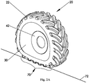
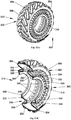
- the locomotion assembly 20 includes a frustum-conical structure 30, which in this example is associated with a ground-engaging member 22 (constituting a surface-engaging member), and serves as a support structure for supporting ground-engaging member 22.
- the ground-engaging member 22 has an overall structure resembling that of a tractor's tyre. As can be seen, particularly in Fig. 2C , defined below the ground-engaging member 22 defines a circumferential tight space 24. This space 24 can be inflated with compressed gas or liquid for controlling resiliency/rigidity.
- the ground-engaging member 22 has downward facing rims 26 and 26A, which are engaged with end portions of the support structure 30, which will be discussed below.
- the support structure 30 includes at least one flexible support member 34.
- the member 34 has a frustum-conical surface extending between a first, relatively wide end 36 and a second narrower end 38, and defining a longitudinal axis A, which in some cases might be substantially horizontally oriented.
- the support member 34 may be formed by a single frustum-conical element, or by multiple support elements defining together said frustum-conical surface.
- the frustum-conical structure serves as a linking structure for transferring force from a vehicle's axle to the rotation axis of the locomotion assembly.
- the support member 34 by its first end 36, supports the ground-engaging member 22, and serves as a linking member for transferring force from a vehicle's axle to the rotational axis of the ground-engaging member.
- the first end 36 is fitted within the circumferential recess defined by downward-facing rim 26.
- Radially-extending from the second narrower end 38 is an end plate 42 fitted with a cylindrical hub 44 which, in use, receives an axle of the vehicle (not shown).
- the engagement of the locomotion assembly to a vehicle's axle may be from each one of the sides of the assembly.
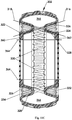
- the support structure 30 preferably include at least one pair of the frustum-conical support members.
- a second frustum-conical support member 50 of the pair is substantially symmetrically identical with the first support member 34, namely has an oppositely-oriented frustum-conical shape of the same conical angle and the same geometry of the wide end thereof, while the same or different height and accordingly the same or different geometry of the narrow end.
- the support members of the pair face each other either by their first (wider) ends or by their second (narrower) ends.
- the support member 50 is mounted over the surface defined by its paired support member 34.
- An external end 60 is fitted into the groove defined by rim 26A.
- the first end 36 of the support member 34 and the external end 60 of the support member 50 are equally distanced from axis A. Consequently, in the configuration shown in Figs. 1A-1C , the locomotion assembly behaves in a wheel-like fashion.
- the locomotion assembly of this embodiment is self-biased to assume a cylindrical configuration with a substantially rounded, side elevation.
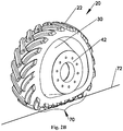
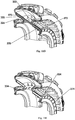
- the locomotion assembly may assume the deformed configuration, as shown in Figs. 2A-2C .
- Figs. 2A-2C show the locomotion assembly in the same views as Figs. 1A-1C but in the deformed configuration.
- a portion 70 which bears onto the ground represented by line 72 (constituting a movement surface), is flattened and essentially parallel to the ground and in contact therewith.
- the locomotion assembly thus has a larger footprint (as illustrated in Fig. 9B ), as compared to the smaller footprint in the wheel-like configuration (illustrated in Fig. 9A ). Therefore, in some respects, in the deformed configuration the locomotion assembly has a caterpillar-like mode of action but without the pulleys that are needed in caterpillars.
- the support structure includes oppositely oriented (symmetrically oriented) frustum-conical support members 34 and 50. As can be seen, in the deformed state, circumferential end 60 of support member 50 and first end 36 of support member 34 are both deformed.
- Figs. 4A-5C showing a locomotion assembly according to another embodiment useful to understand the invention.
- the external end 36 of support member 34 and external end 60 of support member 50 are axially slit by slits 80 to improve flexibility of the entire structure.
- Resiliency of the support structure 30 may be achieved in a variety of ways. By one embodiment, shown in Figs. 1-4 , this is achieved through the use of a rigid though pliable material. In other embodiments, this may be achieved through different solutions.
- One example is end slits 80 of the kind shown in Figs. 5A-5C .
- Examples of other solutions are construction of each of the support members from several segments, articulated to one another at or about the second end.
- One other solution is also disclosed below. The manner of achieving such a structure is within the reach of a person skilled in the art.
- Figs. 6A-6D show a locomotion assembly 90, according to another embodiment useful to understand the invention.
- the ground-engaging member 100 is integrally formed with the support structure 102.
- the resiliency is imparted, among others, by the structure of the ground-engaging member, which is formed having a plurality of slits 104 extending across the ground-engaging member 100 and dividing it into a plurality of segments 106.
- This embodiment includes also an actuating member 120 which, in this exemplary case, is an inflatable, torus-shaped hollow body, which bears against an inside surface 124 of the support structure 102.
- Actuating member 120 When inflated, it imparts rigidity and hence a circular shape; and when deflated, the traction assembly can assume a deformed, flattened configuration.
- Actuating member 120 may by other embodiments be disposed at the opposite side of the wheel. By other embodiments it may include an arrangement with parts on opposite side of the wheel.
- a ground-engaging member 130 is a separately formed body that is made to be flexible by slits 132 formed in the sides of ground-engaging member 130.
- a support structure 134 includes a pair of symmetrically (oppositely) oriented frustum-conical support members 136 and 140, and an end member 138 being an auxiliary support member.
- the support members 136 and 140 have the same geometry at their first wide ends (external ends of the support structure) and equal conical angle, but in this example they have different lengths and accordingly different dimensions at their second narrower ends.
- the wider ends of the support members by which they are to support the ground-engaging member define planar external surfaces of the support structure (planar bases of the support members).
- the auxiliary support member 138 also has a frustum-conical shape oriented similar to that of support member 136. As can best be seen in Fig. 7C the different components are assembled together and may be fitted with one another through one or more of pressure fitting, welding to one another, through knits, screws and many others.
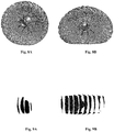
- Exemplary models of the locomotion assembly are shown in Fig. 8A in its circular configuration and in Fig. 8B in its deformed configuration.
- the corresponding footprints of these model embodiments are shown in Figs. 9A and 9B , respectively.
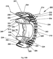
- a locomotion assembly 200 including a flexible ground-engaging member 202 with a ground engaging surface 204, and a flexible support structure 220.
- the locomotion assembly 200 has a wheel-like, essentially circular configuration as shown and has the flexibility to assume a flattened, non-circular configuration, with the ground-engaging surface 204 being in contact with the ground throughout an extended segment thereof (as will be explained below).
- the ground-engaging member 202 has first and second rims 206 and 208 at a first side 210 and second side 212 of the locomotion assembly, respectively.
- the ground-engaging member 202 is supported by the flexible support structure 220 which includes two support arrangements that are both frustum-conical members made of a number of cooperating components that jointly define two, oppositely oriented frustum-conical surfaces as outlined by lines 216 and 218. These frustum-conical surfaces extend from their first ends at rims 206 and 208 to their second, narrower diameter ends 222 and 224. It should be noted that the frustum-conical arrangements have a true frustum-conical shape only in the circular, wheel-like configuration and are shifted into their deformed frustum-conical shape once the traction assembly assumes a non-circular configuration.
- Each support arrangement includes a first portion 226 coupled to (integral with) the ground-engaging member 202, a second portion 228 and a mid-portion defined by a plurality of spikes 230.
- the mid-portions of the two support arrangements cross one another with the plurality of spikes 230, forming an interlacing arrangement.
- the first portion 226 and the second portion 228 are, in this specific embodiment, coupled to (integral with) one another.
- each of sides 210 and 212 formed at each of sides 210 and 212 are respective V-shaped circular grooves 232 and 234, each with walls that are defined by first portions 226 and second, integral portion 228 (of the other support arrangement).
- the locomotion assembly of this embodiment is integrally formed with a rigid hub 252 for linking to a vehicle's axle.
- the entire structure is made of metal.
- the ground-engaging member is comprised of individual segments 240, separated from one another by cuts 242. This ensures an overall flexibility of the ground-engaging member 202.
- the interlacing arrangement of the two support members/arrangements imparts overall ability of radial compression; and accordingly, the ability of the entire locomotion assembly to assume a flattened, non-circular shape, with an extended portion of the ground-engaging surface 204 touching the ground and providing a more extensive locomotion surface.
- a tube or another resilient enclosure may be included in either one or both of spaces 247 and 249 defined within the locomotion assembly.
- FIG. 11A-11E showing a locomotion assembly 300 according to another embodiment according to the invention. Elements having the same function as in locomotion assembly 200 of Figs. 10A and 10B are given the same reference numerals shifted by one hundred.
- the locomotion assembly is made of an elastomeric material, such as rubber, for example of the kind routinely used in wheels. However, other types of materials may be used as well.
- annular shoulders 360 and 362 for fitting over a hub (not shown) and represented by dotted lines 364 in Fig. 11C . Consequently, a circumferential enclosure 366 is formed, defined by the ground-engaging member 302, first and second portions 326 and 324 and between the hub.
- the enclosure 366 may contain compressed gas, e.g. compressed air, and the pressure controls the overall configuration. At high pressure, the locomotion assembly will assume a circular, wheel-like configuration. Once the pressure is reduced, the wheel structure can compress and assume a flattened, non-circular configuration with more extensive locomotion surface.
- Fig. 11D shows a large section of the traction assembly with the spikes 330, each received within a cavity 370, formed within first portion 326; and bore 372, formed within second portion 328.
- Fig. 11E showing the same view with the spikes removed, there is a plurality of openings 374 at end 324, through which the spikes can be inserted to pass through bore 372 and to be received also within cavity 370.
- the spikes provide a functional link defining first portion 326 and second portion 328 as belonging to one functional support arrangement.
- the spikes provide the rigidity to the support structure while the elastomeric portions provide the flexibility.
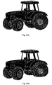
- Figs. 11A-11E The locomotion assembly of the kind shown in Figs. 11A-11E is shown in Figs. 12A and 12B in the circular, wheel-like configuration and in a deformed, flattened configuration, respectively.
- a tractor with such a wheel in the same respective configurations is shown in Figs 13A and 13B .
- the frustum-conical structure of the locomotion assembly of the invention may be configured from two or more elements made form any suitable material, iron or polymer for example, provided that this configuration defines frustum-conical geometry as described above.
- Figs. 14A and 14B illustrate a wheel structure which similar to that of Figs. 10-11 utilizes engaging frustum-conical members, but in which, instead of using the tubular or the like resilient enclosure, the entire frustum-conical support structure 420 is formed from a suitable material, such as a sheet of steel.
- frustum-conical structure formed by at least one frustum-conical member or preferably at least a pair of oppositely (substantially symmetrically) oriented frustum-conical support members, provides for transferring a force from the vehicle's axle to the surface engaging member via the frustum-conical support members.
- a force transfer mechanism within the locomotion assembly.
- the support structure is formed by two frustum-conical support members, one being larger and actually providing the main support for the ground-engaging member and the other being smaller (shorter) and acting to induce the support structure to move in a linear direction, which otherwise (if formed by the single frustum-conical support member) would move in a radial direction, which is natural direction of rolling for a frustum-conical structure.
- the support structure is configured such that a bias of each of the support members of a pair to induce the surface engaging member to move in a non-linear direction is offset by the other support member of the pair.
- the two frustum-conical support members are arranged in a so-called "crossing" fashion due to a gripping pattern (spikes) at the frustum-conical surfaces of the support members.
- the support structure may have no gripping pattern enabling engagement or crossing between the frustum-conical support members, but rather the frustum-conical members of the pair may be separate elements, e.g. spaced-apart from each other.
- Figs. 15A and 15B showing a frustum-conical structure 520 formed by a pair of oppositely oriented spatially separated members, having continuous frustum-conical surfaces.
- the support structures of Figs. 14A-14B and 15A-15B may be embedded within an elastomeric matrix to form an inflatable wheel that can be fitted onto existing wheel drums.
- the two frustum-conical support members of a pair may thus be either crossing (engaging) one another or separated, and may face each other by their identical wide ends or by their narrow ends (identical or not).
- two frustum-conical members may be configured such that each of them is divided into two parts in a manner that there is no such region where segments of one frustum-conical member pass into the other frustum-conical member, but rather a small part of one member is coupled in a partial flexible manner to a larger part of the other oppositely oriented member.
- the configuration of the frustum-conical structure is such that an external circumferential part of the structure, which may be coupled (directly or not) to the surface-engaging member, executes coupling between the two oppositely oriented frustum-conical members, via their common axis, due to coupling between the other part of the structure to the vehicle's axle.
Landscapes
- Engineering & Computer Science (AREA)
- Mechanical Engineering (AREA)
- Tires In General (AREA)
- Percussive Tools And Related Accessories (AREA)
- Fittings On The Vehicle Exterior For Carrying Loads, And Devices For Holding Or Mounting Articles (AREA)
Claims (9)
- Ein Fortbewegungsaufbau (200; 300; 400) für ein Landfahrzeug, wobei der Fortbewegungsaufbau (200; 300; 400) Folgendes umfasst:ein flexibles, elastomeres Bodeneingriffsglied (202; 302), das eine radähnliche, im Wesentlichen kreisförmige Konfiguration mit einer Bodeneingriffsfläche (204, 304) mit ersten und zweiten Rändern (206, 208; 306, 308) hat, die ersten und zweiten Seiten (210, 212; 310, 312) des Fortbewegungsaufbaus (200; 300) entsprechen, undein Paar kegelstumpfförmiger Glieder (216, 218; 316, 318), integral geformt mit dem Bodeneingriffsglied (202; 302), wobei jedes der kegelstumpfförmigen Glieder des Paares sich zwischen seinem relativ schmalen (222, 224; 322, 324) und seinem relativ breiten Ende entlang einer gemeinsamen kegelstumpfförmigen Achse erstreckt und um die Achse drehbar ist, wobei jedes der kegelstumpfförmigen Glieder des Paares eine Vielzahl starrer Dornen (230; 330) umfasst, die gemeinsam einen mittleren Abschnitt des kegelstumpfförmigen Glieds bestimmen, der die ersten und zweiten Endabschnitte (226, 326; 228, 328) desselben verbindet und in Schlitze (372) aufgenommen wird, die im ersten und im zweiten Abschnitt bestimmt sind, wodurch ein ein Gitter ermöglichender Eingriff zwischen den kegelstumpfförmigen Gliedern des Paares gebildet wird;wobei die kegelstumpfförmigen Glieder des Paares symmetrisch ausgerichtet sind, gemeinsam an ihren breiten Enden das Bodeneingriffsglied tragen, dadurch erste und zweite kreisähnliche, im Wesentlichen V-förmige, Nuten (232, 234; 332, 334) in den ersten beziehungsweise zweiten Seiten (210, 212; 310, 312) des Fortbewegungsaufbaus (200; 300) bestimmend; wobei jede der V-förmigen Nuten bestimmt ist durch eine erste, stärker periphere Wand (226; 326) und eine zweite, stärker zentrale Wand (228; 328) der jeweiligen Seite des Fortbewegungsaufbaus, wobei die ersten und zweiten Wände der Nut durch Oberflächen der ersten und zweiten kegelstumpfförmigen Glieder des Paares (216, 218; 316, 318) gebildet werden, wodurch die ersten und zweiten V-förmigen Nuten mit entgegengesetzter symmetrischer Ausrichtung angeordnet sind, für eine radiale Kompression des Fortbewegungsaufbaus durch reversible Verformung der ersten und zweiten Nuten sorgend, dadurch eine reversible Verformung des Bodeneingriffsglieds (202; 302) aus einer im Wesentlichen kreisähnlichen Form in eine verformte Form ermöglichend, in welcher ein größerer Abschnitt der Bodeneingriffsfläche in Kontakt mit einer Bewegungsoberfläche steht.
- Der Fortbewegungsaufbau gemäß Anspruch 1, wobei jedes der kegelstumpfförmigen Glieder des Paares am breiten Ende desselben mit einer Seite des Bodeneingriffsglieds gekoppelt ist, die derjenigen des anderen gegenüberliegt.
- Der Fortbewegungsaufbau gemäß Anspruch 1 oder 2, wobei die kegelstumpfförmigen Glieder des Paares aus einem starren Material bestehen und biegsam und in eine gerundete Form vorgespannt sind, in welcher ihr Seitenriss kreisförmig ist, und reversibel in eine stärker abgeflachte Form verformbar sind, in welcher ihr Seitenriss nicht kreisförmig ist.
- Der Fortbewegungsaufbau gemäß einem beliebigen der Ansprüche 1 bis 3, der eine Betätigungsanordnung (120) umfasst, um das Bodeneingriffsglied zu zwingen, eine seiner Konfigurationen anzunehmen.
- Der Fortbewegungsaufbau gemäß Anspruch 4, wobei die Betätigungsanordnung pneumatisch ist.
- Der Fortbewegungsaufbau gemäß Anspruch 4 oder 5, der ein Gehäuse (366) für Druckgas umfasst, wobei der Druck des Gases die Konfiguration des Fortbewegungsaufbaus steuert.
- Der Fortbewegungsaufbau gemäß Anspruch 6, wobei ein hoher Gasdruck den Fortbewegungsaufbau dazu veranlasst, eine radähnliche Konfiguration anzunehmen, und eine Absenkung des Gasdrucks es dem Fortbewegungsaufbau ermöglicht, eine nicht kreisförmige Konfiguration anzunehmen.
- Der Fortbewegungsaufbau gemäß einem beliebigen der Ansprüche 1 bis 7, wobei das erste kegelstumpfförmige Glied des Paares sich zwischen dem ersten Rand des Bodeneingriffsglieds zu der zweiten Seite des Rades erstreckt und das zweite kegelstumpfförmige Glied des Paares sich zwischen dem zweiten Rand des Bodeneingriffsglieds zu der ersten Seite des Rades erstreckt, wobei die beiden kegelstumpfförmigen Glieder des Paares sich in einem mittleren Abschnitt kreuzen, der einen Wendeabschnitt der V-förmigen Nut bestimmt.
- Der Fortbewegungsaufbau gemäß einem beliebigen der Ansprüche 1 bis 8, wobei das flexible, elastomere Bodeneingriffsglied einen aufblasbaren Gummireifen umfasst, der einen eingeschlossenen Fluiddruck haltenden Raum (24) bestimmt, dessen Umfang die Bodeneingriffsfläche bestimmt.
Applications Claiming Priority (4)
| Application Number | Priority Date | Filing Date | Title |
|---|---|---|---|
| US30015910P | 2010-02-01 | 2010-02-01 | |
| US35916110P | 2010-06-28 | 2010-06-28 | |
| EP11706363.6A EP2531360B1 (de) | 2010-02-01 | 2011-02-01 | Deformierbare radeinheit |
| PCT/IL2011/000115 WO2011092709A1 (en) | 2010-02-01 | 2011-02-01 | Deformable wheel assembly |
Related Parent Applications (1)
| Application Number | Title | Priority Date | Filing Date |
|---|---|---|---|
| EP11706363.6A Division EP2531360B1 (de) | 2010-02-01 | 2011-02-01 | Deformierbare radeinheit |
Publications (3)
| Publication Number | Publication Date |
|---|---|
| EP2853414A2 EP2853414A2 (de) | 2015-04-01 |
| EP2853414A3 EP2853414A3 (de) | 2015-04-08 |
| EP2853414B1 true EP2853414B1 (de) | 2019-09-18 |
Family
ID=43971242
Family Applications (2)
| Application Number | Title | Priority Date | Filing Date |
|---|---|---|---|
| EP14188573.1A Active EP2853414B1 (de) | 2010-02-01 | 2011-02-01 | Deformierbare radeinheit |
| EP11706363.6A Active EP2531360B1 (de) | 2010-02-01 | 2011-02-01 | Deformierbare radeinheit |
Family Applications After (1)
| Application Number | Title | Priority Date | Filing Date |
|---|---|---|---|
| EP11706363.6A Active EP2531360B1 (de) | 2010-02-01 | 2011-02-01 | Deformierbare radeinheit |
Country Status (17)
| Country | Link |
|---|---|
| US (2) | US9656515B2 (de) |
| EP (2) | EP2853414B1 (de) |
| JP (2) | JP6002042B2 (de) |
| KR (1) | KR101851809B1 (de) |
| CN (1) | CN102712212B (de) |
| AU (1) | AU2011210371B2 (de) |
| BR (1) | BR112012018974B1 (de) |
| CA (1) | CA2787885C (de) |
| DK (1) | DK2531360T3 (de) |
| ES (1) | ES2527852T3 (de) |
| IL (2) | IL220961A (de) |
| MX (1) | MX2012008870A (de) |
| MY (1) | MY183836A (de) |
| PL (1) | PL2531360T3 (de) |
| PT (1) | PT2531360E (de) |
| RU (2) | RU2557642C2 (de) |
| WO (1) | WO2011092709A1 (de) |
Families Citing this family (14)
| Publication number | Priority date | Publication date | Assignee | Title |
|---|---|---|---|---|
| EP2853414B1 (de) | 2010-02-01 | 2019-09-18 | Galileo Wheel Ltd. | Deformierbare radeinheit |
| BR112014001559B1 (pt) | 2011-07-27 | 2020-12-01 | Galileo Wheel Ltd. | conjunto de roda para um veículo de superfície e veículo |
| RU2508993C1 (ru) * | 2012-06-20 | 2014-03-10 | Александр Александрович Панфилов | Шина транспортного средства |
| CA2900126A1 (en) * | 2014-08-11 | 2016-02-11 | Raven Industries, Inc. | Composite film and method for fabricating same |
| US10442252B2 (en) * | 2015-04-09 | 2019-10-15 | Jeffrey P Douglas | Tire with high strength corrugated sidewalls |
| US10500896B2 (en) * | 2015-12-28 | 2019-12-10 | Paul Catalano | Flexible wheel assembly |
| RU167698U1 (ru) * | 2016-08-01 | 2017-01-10 | Сергей Анатольевич Машанов | Колесо транспортного средства |
| MX2018015661A (es) | 2016-09-25 | 2019-06-10 | Galileo Wheel Ltd | Llanta neumatica con concavidad de la pared lateral anular. |
| EP3727885B1 (de) * | 2017-12-21 | 2022-06-15 | Compagnie Generale Des Etablissements Michelin | Luftloser reifen mit verstärktem ringträger |
| CN108790591B (zh) * | 2018-05-04 | 2020-02-07 | 北京交通大学 | 一种可变形轮式机器人 |
| US11267283B2 (en) | 2019-04-05 | 2022-03-08 | Honda Motor Co., Ltd. | Omni-direction wheel system and methods for controlling the omni-direction wheel system |
| BR102020013868A2 (pt) | 2019-07-07 | 2021-01-12 | Galileo Wheel Ltd. | Montagem de roda, método para fixar uma montagem de roda e sistema de pneu e clipe de trava de talão |
| KR102312919B1 (ko) | 2020-05-25 | 2021-10-18 | 한국타이어앤테크놀로지 주식회사 | 퍼즐식 결합체를 구비하는 타이어 휠 |
| US20230311571A1 (en) * | 2022-03-30 | 2023-10-05 | The Goodyear Tire & Rubber Company | Non-pneumatic tire or wheel with reinforced rubber spokes |
Family Cites Families (45)
| Publication number | Priority date | Publication date | Assignee | Title |
|---|---|---|---|---|
| DE209209C (de) * | ||||
| DE66733C (de) * | J. B. DUNLOP, Thierarzt, in Belfast, Grafschaft Antrim, Irland | Federndes Rad für Fahrräder und Fahrzeuge | ||
| US597569A (en) | 1898-01-18 | Edwin | ||
| US595422A (en) | 1897-12-14 | Edwin g | ||
| NL41125C (de) * | ||||
| US1462440A (en) * | 1922-05-15 | 1923-07-17 | Arthur E Bauman | Spring tire |
| US1832405A (en) * | 1929-04-17 | 1931-11-17 | Mayer Julius | Vehicle wheel |
| US2331024A (en) * | 1942-05-30 | 1943-10-05 | James E Griffith | Spring tire for vehicles |
| US2491698A (en) * | 1945-09-07 | 1949-12-20 | Henry W Walden | Shock-absorbing wheel |
| US2463226A (en) * | 1947-02-21 | 1949-03-01 | Henry W Walden | Laterally stabilized wheel of the load-suspension type |
| BE560044A (de) | 1954-02-26 | |||
| US2798525A (en) * | 1956-09-07 | 1957-07-09 | Rand Goetze Corp | Vehicle wheel |
| DE1073332B (de) | 1956-10-25 | 1960-01-14 | Ing Herbert Merz Hannover Dr | Unter Luftdruck stehender Reifen, insbesondere für Fahrzeuge |
| NL262749A (de) | 1960-12-30 | |||
| US3242965A (en) | 1964-01-13 | 1966-03-29 | Fr Du Pneu Englebert Soc | Pneumatic casing |
| NL135522B (de) | 1965-07-31 | |||
| US3394751A (en) | 1966-08-05 | 1968-07-30 | Goodrich Co B F | Penumatic expansible tire with folding sidewalls and rubber cushions at the beads |
| US3400746A (en) | 1966-08-11 | 1968-09-10 | Goodrich Co B F | Pneumatic expansible tire having resiliently folding sidewalls |
| US3590897A (en) | 1969-10-21 | 1971-07-06 | Edwin C Bragdon | Spider wheel |
| US3698461A (en) * | 1969-12-18 | 1972-10-17 | Grumman Aerospace Corp | Elastic conoid shaped wheel |
| JPS517602Y2 (de) * | 1971-03-22 | 1976-03-01 | ||
| GB1380267A (en) | 1971-06-09 | 1975-01-08 | Gkn Group Services Ltd | Wheels |
| DE2135960A1 (de) * | 1971-07-19 | 1973-02-01 | Becker Ewald | Mehrteilige kraftfahrzeugfelge |
| BE786511A (fr) | 1971-07-30 | 1973-01-22 | Pirelli | Bandage pneumatique pour roues de vehicules |
| NL7315541A (de) | 1971-07-30 | 1974-08-26 | ||
| FR2314059A1 (fr) | 1975-06-12 | 1977-01-07 | Michelin & Cie | Enveloppes de pneumatiques sans armature |
| US4308907A (en) | 1976-06-23 | 1982-01-05 | Renato Monzini | Vehicle tire and wheel construction with selective deformability |
| US4137960A (en) * | 1977-11-07 | 1979-02-06 | General Motors Corporation | Run-flat tire having internal support means |
| CA1128410A (en) | 1979-12-03 | 1982-07-27 | Thomas N.H. Welter | Compression sidewall tire |
| US4739810A (en) * | 1985-06-17 | 1988-04-26 | Grumman Aerospace Corporation | Convoluted cone wheel |
| US4936365A (en) | 1988-12-12 | 1990-06-26 | The Goodyear Tire & Rubber Company | Anisotropic tire |
| US6495513B1 (en) | 1991-03-11 | 2002-12-17 | Curis, Inc. | Morphogen-enhanced survival and repair of neural cells |
| DE29702598U1 (de) | 1997-02-14 | 1997-04-03 | Techno Finish GmbH, 99846 Seebach | Laufrad für Staubsaugerdüse |
| IL122062A (en) * | 1997-10-29 | 2000-08-13 | Galileo Mobility Instr Ltd | Transporting system |
| JP2001121929A (ja) | 1999-10-29 | 2001-05-08 | Toyo Tire & Rubber Co Ltd | 波形ランフラットタイヤ |
| DE10131696B4 (de) | 2001-06-29 | 2006-11-23 | BSH Bosch und Siemens Hausgeräte GmbH | Staubsauger |
| CA2462247C (en) | 2001-10-03 | 2009-09-08 | Galileo Mobility Instruments Ltd. | Adaptable traction system of a vehicle |
| JP2003136921A (ja) * | 2001-11-08 | 2003-05-14 | Bridgestone Corp | 空気入りタイヤおよびタイヤとリムとの組み立て体 |
| CN1729110B (zh) | 2002-12-26 | 2010-10-13 | 米其林技术公司 | 带有可变刚性侧壁的漏气保用轮胎 |
| WO2005063505A1 (en) * | 2003-12-22 | 2005-07-14 | Pieter Johannes Labuschagne | Non-pneumatic tyre |
| JP4943994B2 (ja) | 2007-02-08 | 2012-05-30 | ヤマハ発動機株式会社 | ブレーキ装置、及び鞍乗型車両 |
| US20080197695A1 (en) | 2007-02-20 | 2008-08-21 | Kyosuke Uemura | Wheels having superior shock absorption and transport devices usint the same |
| US7726371B2 (en) | 2007-06-27 | 2010-06-01 | Morrison Glenn A | High-efficiency wheel product |
| US20090173421A1 (en) * | 2008-01-08 | 2009-07-09 | Freudenberg-Nok General Partnership | Flatless Hybrid Isolated Tire |
| EP2853414B1 (de) | 2010-02-01 | 2019-09-18 | Galileo Wheel Ltd. | Deformierbare radeinheit |
-
2011
- 2011-02-01 EP EP14188573.1A patent/EP2853414B1/de active Active
- 2011-02-01 WO PCT/IL2011/000115 patent/WO2011092709A1/en not_active Ceased
- 2011-02-01 BR BR112012018974-3A patent/BR112012018974B1/pt not_active IP Right Cessation
- 2011-02-01 KR KR1020127019765A patent/KR101851809B1/ko active Active
- 2011-02-01 DK DK11706363.6T patent/DK2531360T3/en active
- 2011-02-01 JP JP2012550570A patent/JP6002042B2/ja active Active
- 2011-02-01 RU RU2012136381/11A patent/RU2557642C2/ru active
- 2011-02-01 US US13/576,587 patent/US9656515B2/en active Active
- 2011-02-01 ES ES11706363.6T patent/ES2527852T3/es active Active
- 2011-02-01 EP EP11706363.6A patent/EP2531360B1/de active Active
- 2011-02-01 CN CN201180006334.4A patent/CN102712212B/zh not_active Expired - Fee Related
- 2011-02-01 CA CA2787885A patent/CA2787885C/en active Active
- 2011-02-01 PL PL11706363T patent/PL2531360T3/pl unknown
- 2011-02-01 MX MX2012008870A patent/MX2012008870A/es active IP Right Grant
- 2011-02-01 PT PT117063636T patent/PT2531360E/pt unknown
- 2011-02-01 MY MYPI2012003192A patent/MY183836A/en unknown
- 2011-02-01 RU RU2015120636A patent/RU2681674C2/ru active
- 2011-02-01 AU AU2011210371A patent/AU2011210371B2/en not_active Ceased
-
2012
- 2012-07-16 IL IL220961A patent/IL220961A/en active IP Right Grant
-
2016
- 2016-09-02 JP JP2016171763A patent/JP6364459B2/ja active Active
-
2017
- 2017-05-10 IL IL252217A patent/IL252217B/en active IP Right Grant
- 2017-05-15 US US15/595,099 patent/US10518575B2/en active Active
Non-Patent Citations (1)
| Title |
|---|
| None * |
Also Published As
Similar Documents
| Publication | Publication Date | Title |
|---|---|---|
| EP2853414B1 (de) | Deformierbare radeinheit | |
| EP3057807B1 (de) | Luftloser reifen mit reduzierter quersteifigkeit | |
| CN101223042A (zh) | 非充气的轮胎组件 | |
| JP2013518755A5 (de) | ||
| US10343456B2 (en) | Tire for surface vehicle | |
| WO2005063505A1 (en) | Non-pneumatic tyre | |
| EP3808573B1 (de) | Rad mit variabler nachgiebigkeit mit drehmomentmessvorrichtung | |
| US3620278A (en) | Hybrid pneumatic-mechanical variable configuration wheel | |
| US20200324575A1 (en) | Non-pneumatic tire having offset spokes |
Legal Events
| Date | Code | Title | Description |
|---|---|---|---|
| PUAL | Search report despatched |
Free format text: ORIGINAL CODE: 0009013 |
|
| PUAI | Public reference made under article 153(3) epc to a published international application that has entered the european phase |
Free format text: ORIGINAL CODE: 0009012 |
|
| 17P | Request for examination filed |
Effective date: 20141011 |
|
| AC | Divisional application: reference to earlier application |
Ref document number: 2531360 Country of ref document: EP Kind code of ref document: P |
|
| AK | Designated contracting states |
Kind code of ref document: A2 Designated state(s): AL AT BE BG CH CY CZ DE DK EE ES FI FR GB GR HR HU IE IS IT LI LT LU LV MC MK MT NL NO PL PT RO RS SE SI SK SM TR |
|
| AX | Request for extension of the european patent |
Extension state: BA ME |
|
| AK | Designated contracting states |
Kind code of ref document: A3 Designated state(s): AL AT BE BG CH CY CZ DE DK EE ES FI FR GB GR HR HU IE IS IT LI LT LU LV MC MK MT NL NO PL PT RO RS SE SI SK SM TR |
|
| AX | Request for extension of the european patent |
Extension state: BA ME |
|
| RIC1 | Information provided on ipc code assigned before grant |
Ipc: B60B 9/00 20060101ALI20150303BHEP Ipc: B60B 19/00 20060101AFI20150303BHEP |
|
| R17P | Request for examination filed (corrected) |
Effective date: 20151008 |
|
| RBV | Designated contracting states (corrected) |
Designated state(s): AL AT BE BG CH CY CZ DE DK EE ES FI FR GB GR HR HU IE IS IT LI LT LU LV MC MK MT NL NO PL PT RO RS SE SI SK SM TR |
|
| STAA | Information on the status of an ep patent application or granted ep patent |
Free format text: STATUS: EXAMINATION IS IN PROGRESS |
|
| 17Q | First examination report despatched |
Effective date: 20180514 |
|
| GRAP | Despatch of communication of intention to grant a patent |
Free format text: ORIGINAL CODE: EPIDOSNIGR1 |
|
| STAA | Information on the status of an ep patent application or granted ep patent |
Free format text: STATUS: GRANT OF PATENT IS INTENDED |
|
| INTG | Intention to grant announced |
Effective date: 20190410 |
|
| GRAS | Grant fee paid |
Free format text: ORIGINAL CODE: EPIDOSNIGR3 |
|
| GRAA | (expected) grant |
Free format text: ORIGINAL CODE: 0009210 |
|
| STAA | Information on the status of an ep patent application or granted ep patent |
Free format text: STATUS: THE PATENT HAS BEEN GRANTED |
|
| AC | Divisional application: reference to earlier application |
Ref document number: 2531360 Country of ref document: EP Kind code of ref document: P |
|
| AK | Designated contracting states |
Kind code of ref document: B1 Designated state(s): AL AT BE BG CH CY CZ DE DK EE ES FI FR GB GR HR HU IE IS IT LI LT LU LV MC MK MT NL NO PL PT RO RS SE SI SK SM TR |
|
| REG | Reference to a national code |
Ref country code: GB Ref legal event code: FG4D |
|
| REG | Reference to a national code |
Ref country code: CH Ref legal event code: EP |
|
| REG | Reference to a national code |
Ref country code: DE Ref legal event code: R096 Ref document number: 602011062246 Country of ref document: DE |
|
| REG | Reference to a national code |
Ref country code: AT Ref legal event code: REF Ref document number: 1180830 Country of ref document: AT Kind code of ref document: T Effective date: 20191015 |
|
| REG | Reference to a national code |
Ref country code: IE Ref legal event code: FG4D |
|
| REG | Reference to a national code |
Ref country code: NL Ref legal event code: FP |
|
| PG25 | Lapsed in a contracting state [announced via postgrant information from national office to epo] |
Ref country code: FI Free format text: LAPSE BECAUSE OF FAILURE TO SUBMIT A TRANSLATION OF THE DESCRIPTION OR TO PAY THE FEE WITHIN THE PRESCRIBED TIME-LIMIT Effective date: 20190918 Ref country code: LT Free format text: LAPSE BECAUSE OF FAILURE TO SUBMIT A TRANSLATION OF THE DESCRIPTION OR TO PAY THE FEE WITHIN THE PRESCRIBED TIME-LIMIT Effective date: 20190918 Ref country code: BG Free format text: LAPSE BECAUSE OF FAILURE TO SUBMIT A TRANSLATION OF THE DESCRIPTION OR TO PAY THE FEE WITHIN THE PRESCRIBED TIME-LIMIT Effective date: 20191218 Ref country code: NO Free format text: LAPSE BECAUSE OF FAILURE TO SUBMIT A TRANSLATION OF THE DESCRIPTION OR TO PAY THE FEE WITHIN THE PRESCRIBED TIME-LIMIT Effective date: 20191218 Ref country code: HR Free format text: LAPSE BECAUSE OF FAILURE TO SUBMIT A TRANSLATION OF THE DESCRIPTION OR TO PAY THE FEE WITHIN THE PRESCRIBED TIME-LIMIT Effective date: 20190918 Ref country code: SE Free format text: LAPSE BECAUSE OF FAILURE TO SUBMIT A TRANSLATION OF THE DESCRIPTION OR TO PAY THE FEE WITHIN THE PRESCRIBED TIME-LIMIT Effective date: 20190918 |
|
| REG | Reference to a national code |
Ref country code: LT Ref legal event code: MG4D |
|
| PG25 | Lapsed in a contracting state [announced via postgrant information from national office to epo] |
Ref country code: RS Free format text: LAPSE BECAUSE OF FAILURE TO SUBMIT A TRANSLATION OF THE DESCRIPTION OR TO PAY THE FEE WITHIN THE PRESCRIBED TIME-LIMIT Effective date: 20190918 Ref country code: GR Free format text: LAPSE BECAUSE OF FAILURE TO SUBMIT A TRANSLATION OF THE DESCRIPTION OR TO PAY THE FEE WITHIN THE PRESCRIBED TIME-LIMIT Effective date: 20191219 Ref country code: LV Free format text: LAPSE BECAUSE OF FAILURE TO SUBMIT A TRANSLATION OF THE DESCRIPTION OR TO PAY THE FEE WITHIN THE PRESCRIBED TIME-LIMIT Effective date: 20190918 Ref country code: AL Free format text: LAPSE BECAUSE OF FAILURE TO SUBMIT A TRANSLATION OF THE DESCRIPTION OR TO PAY THE FEE WITHIN THE PRESCRIBED TIME-LIMIT Effective date: 20190918 |
|
| REG | Reference to a national code |
Ref country code: AT Ref legal event code: MK05 Ref document number: 1180830 Country of ref document: AT Kind code of ref document: T Effective date: 20190918 |
|
| PG25 | Lapsed in a contracting state [announced via postgrant information from national office to epo] |
Ref country code: PL Free format text: LAPSE BECAUSE OF FAILURE TO SUBMIT A TRANSLATION OF THE DESCRIPTION OR TO PAY THE FEE WITHIN THE PRESCRIBED TIME-LIMIT Effective date: 20190918 Ref country code: AT Free format text: LAPSE BECAUSE OF FAILURE TO SUBMIT A TRANSLATION OF THE DESCRIPTION OR TO PAY THE FEE WITHIN THE PRESCRIBED TIME-LIMIT Effective date: 20190918 Ref country code: EE Free format text: LAPSE BECAUSE OF FAILURE TO SUBMIT A TRANSLATION OF THE DESCRIPTION OR TO PAY THE FEE WITHIN THE PRESCRIBED TIME-LIMIT Effective date: 20190918 Ref country code: PT Free format text: LAPSE BECAUSE OF FAILURE TO SUBMIT A TRANSLATION OF THE DESCRIPTION OR TO PAY THE FEE WITHIN THE PRESCRIBED TIME-LIMIT Effective date: 20200120 Ref country code: RO Free format text: LAPSE BECAUSE OF FAILURE TO SUBMIT A TRANSLATION OF THE DESCRIPTION OR TO PAY THE FEE WITHIN THE PRESCRIBED TIME-LIMIT Effective date: 20190918 Ref country code: ES Free format text: LAPSE BECAUSE OF FAILURE TO SUBMIT A TRANSLATION OF THE DESCRIPTION OR TO PAY THE FEE WITHIN THE PRESCRIBED TIME-LIMIT Effective date: 20190918 |
|
| PG25 | Lapsed in a contracting state [announced via postgrant information from national office to epo] |
Ref country code: SK Free format text: LAPSE BECAUSE OF FAILURE TO SUBMIT A TRANSLATION OF THE DESCRIPTION OR TO PAY THE FEE WITHIN THE PRESCRIBED TIME-LIMIT Effective date: 20190918 Ref country code: IS Free format text: LAPSE BECAUSE OF FAILURE TO SUBMIT A TRANSLATION OF THE DESCRIPTION OR TO PAY THE FEE WITHIN THE PRESCRIBED TIME-LIMIT Effective date: 20200224 Ref country code: SM Free format text: LAPSE BECAUSE OF FAILURE TO SUBMIT A TRANSLATION OF THE DESCRIPTION OR TO PAY THE FEE WITHIN THE PRESCRIBED TIME-LIMIT Effective date: 20190918 |
|
| REG | Reference to a national code |
Ref country code: DE Ref legal event code: R097 Ref document number: 602011062246 Country of ref document: DE |
|
| PLBE | No opposition filed within time limit |
Free format text: ORIGINAL CODE: 0009261 |
|
| STAA | Information on the status of an ep patent application or granted ep patent |
Free format text: STATUS: NO OPPOSITION FILED WITHIN TIME LIMIT |
|
| PG2D | Information on lapse in contracting state deleted |
Ref country code: IS |
|
| PG25 | Lapsed in a contracting state [announced via postgrant information from national office to epo] |
Ref country code: DK Free format text: LAPSE BECAUSE OF FAILURE TO SUBMIT A TRANSLATION OF THE DESCRIPTION OR TO PAY THE FEE WITHIN THE PRESCRIBED TIME-LIMIT Effective date: 20190918 Ref country code: IS Free format text: LAPSE BECAUSE OF FAILURE TO SUBMIT A TRANSLATION OF THE DESCRIPTION OR TO PAY THE FEE WITHIN THE PRESCRIBED TIME-LIMIT Effective date: 20200119 |
|
| 26N | No opposition filed |
Effective date: 20200619 |
|
| PG25 | Lapsed in a contracting state [announced via postgrant information from national office to epo] |
Ref country code: SI Free format text: LAPSE BECAUSE OF FAILURE TO SUBMIT A TRANSLATION OF THE DESCRIPTION OR TO PAY THE FEE WITHIN THE PRESCRIBED TIME-LIMIT Effective date: 20190918 |
|
| REG | Reference to a national code |
Ref country code: CH Ref legal event code: PL |
|
| REG | Reference to a national code |
Ref country code: BE Ref legal event code: MM Effective date: 20200229 |
|
| PG25 | Lapsed in a contracting state [announced via postgrant information from national office to epo] |
Ref country code: LU Free format text: LAPSE BECAUSE OF NON-PAYMENT OF DUE FEES Effective date: 20200201 Ref country code: MC Free format text: LAPSE BECAUSE OF FAILURE TO SUBMIT A TRANSLATION OF THE DESCRIPTION OR TO PAY THE FEE WITHIN THE PRESCRIBED TIME-LIMIT Effective date: 20190918 |
|
| PG25 | Lapsed in a contracting state [announced via postgrant information from national office to epo] |
Ref country code: CH Free format text: LAPSE BECAUSE OF NON-PAYMENT OF DUE FEES Effective date: 20200229 Ref country code: LI Free format text: LAPSE BECAUSE OF NON-PAYMENT OF DUE FEES Effective date: 20200229 |
|
| PG25 | Lapsed in a contracting state [announced via postgrant information from national office to epo] |
Ref country code: IE Free format text: LAPSE BECAUSE OF NON-PAYMENT OF DUE FEES Effective date: 20200201 |
|
| PG25 | Lapsed in a contracting state [announced via postgrant information from national office to epo] |
Ref country code: BE Free format text: LAPSE BECAUSE OF NON-PAYMENT OF DUE FEES Effective date: 20200229 |
|
| PG25 | Lapsed in a contracting state [announced via postgrant information from national office to epo] |
Ref country code: TR Free format text: LAPSE BECAUSE OF FAILURE TO SUBMIT A TRANSLATION OF THE DESCRIPTION OR TO PAY THE FEE WITHIN THE PRESCRIBED TIME-LIMIT Effective date: 20190918 Ref country code: MT Free format text: LAPSE BECAUSE OF FAILURE TO SUBMIT A TRANSLATION OF THE DESCRIPTION OR TO PAY THE FEE WITHIN THE PRESCRIBED TIME-LIMIT Effective date: 20190918 Ref country code: CY Free format text: LAPSE BECAUSE OF FAILURE TO SUBMIT A TRANSLATION OF THE DESCRIPTION OR TO PAY THE FEE WITHIN THE PRESCRIBED TIME-LIMIT Effective date: 20190918 |
|
| PG25 | Lapsed in a contracting state [announced via postgrant information from national office to epo] |
Ref country code: MK Free format text: LAPSE BECAUSE OF FAILURE TO SUBMIT A TRANSLATION OF THE DESCRIPTION OR TO PAY THE FEE WITHIN THE PRESCRIBED TIME-LIMIT Effective date: 20190918 |
|
| PGFP | Annual fee paid to national office [announced via postgrant information from national office to epo] |
Ref country code: NL Payment date: 20230215 Year of fee payment: 13 |
|
| PGFP | Annual fee paid to national office [announced via postgrant information from national office to epo] |
Ref country code: GB Payment date: 20230202 Year of fee payment: 13 |
|
| REG | Reference to a national code |
Ref country code: NL Ref legal event code: MM Effective date: 20240301 |
|
| GBPC | Gb: european patent ceased through non-payment of renewal fee |
Effective date: 20240201 |
|
| PG25 | Lapsed in a contracting state [announced via postgrant information from national office to epo] |
Ref country code: NL Free format text: LAPSE BECAUSE OF NON-PAYMENT OF DUE FEES Effective date: 20240301 |
|
| PG25 | Lapsed in a contracting state [announced via postgrant information from national office to epo] |
Ref country code: NL Free format text: LAPSE BECAUSE OF NON-PAYMENT OF DUE FEES Effective date: 20240301 |
|
| PG25 | Lapsed in a contracting state [announced via postgrant information from national office to epo] |
Ref country code: GB Free format text: LAPSE BECAUSE OF NON-PAYMENT OF DUE FEES Effective date: 20240201 |
|
| PG25 | Lapsed in a contracting state [announced via postgrant information from national office to epo] |
Ref country code: GB Free format text: LAPSE BECAUSE OF NON-PAYMENT OF DUE FEES Effective date: 20240201 |
|
| PGFP | Annual fee paid to national office [announced via postgrant information from national office to epo] |
Ref country code: DE Payment date: 20250121 Year of fee payment: 15 |
|
| PGFP | Annual fee paid to national office [announced via postgrant information from national office to epo] |
Ref country code: FR Payment date: 20250121 Year of fee payment: 15 Ref country code: CZ Payment date: 20250127 Year of fee payment: 15 |
|
| PGFP | Annual fee paid to national office [announced via postgrant information from national office to epo] |
Ref country code: IT Payment date: 20250129 Year of fee payment: 15 |