EP2853326B1 - Automatisiert koppelbares Spannfutter - Google Patents
Automatisiert koppelbares Spannfutter Download PDFInfo
- Publication number
- EP2853326B1 EP2853326B1 EP14190524.0A EP14190524A EP2853326B1 EP 2853326 B1 EP2853326 B1 EP 2853326B1 EP 14190524 A EP14190524 A EP 14190524A EP 2853326 B1 EP2853326 B1 EP 2853326B1
- Authority
- EP
- European Patent Office
- Prior art keywords
- chuck
- clamping
- drive motor
- drive
- clamping jaws
- Prior art date
- Legal status (The legal status is an assumption and is not a legal conclusion. Google has not performed a legal analysis and makes no representation as to the accuracy of the status listed.)
- Active
Links
Images

Classifications
-
- B—PERFORMING OPERATIONS; TRANSPORTING
- B23—MACHINE TOOLS; METAL-WORKING NOT OTHERWISE PROVIDED FOR
- B23B—TURNING; BORING
- B23B31/00—Chucks; Expansion mandrels; Adaptations thereof for remote control
- B23B31/02—Chucks
- B23B31/10—Chucks characterised by the retaining or gripping devices or their immediate operating means
- B23B31/101—Chucks with separately-acting jaws movable radially
-
- B—PERFORMING OPERATIONS; TRANSPORTING
- B23—MACHINE TOOLS; METAL-WORKING NOT OTHERWISE PROVIDED FOR
- B23B—TURNING; BORING
- B23B31/00—Chucks; Expansion mandrels; Adaptations thereof for remote control
- B23B31/02—Chucks
- B23B31/10—Chucks characterised by the retaining or gripping devices or their immediate operating means
- B23B31/12—Chucks with simultaneously-acting jaws, whether or not also individually adjustable
- B23B31/16—Chucks with simultaneously-acting jaws, whether or not also individually adjustable moving radially
- B23B31/16004—Jaws movement actuated by one or more spiral grooves
- B23B31/16037—Jaws movement actuated by one or more spiral grooves using mechanical transmission through the spindle
-
- B—PERFORMING OPERATIONS; TRANSPORTING
- B23—MACHINE TOOLS; METAL-WORKING NOT OTHERWISE PROVIDED FOR
- B23B—TURNING; BORING
- B23B31/00—Chucks; Expansion mandrels; Adaptations thereof for remote control
- B23B31/02—Chucks
- B23B31/10—Chucks characterised by the retaining or gripping devices or their immediate operating means
- B23B31/12—Chucks with simultaneously-acting jaws, whether or not also individually adjustable
- B23B31/16—Chucks with simultaneously-acting jaws, whether or not also individually adjustable moving radially
- B23B31/16045—Jaws movement actuated by screws and nuts or oblique racks
-
- B—PERFORMING OPERATIONS; TRANSPORTING
- B23—MACHINE TOOLS; METAL-WORKING NOT OTHERWISE PROVIDED FOR
- B23B—TURNING; BORING
- B23B31/00—Chucks; Expansion mandrels; Adaptations thereof for remote control
- B23B31/02—Chucks
- B23B31/10—Chucks characterised by the retaining or gripping devices or their immediate operating means
- B23B31/12—Chucks with simultaneously-acting jaws, whether or not also individually adjustable
- B23B31/16—Chucks with simultaneously-acting jaws, whether or not also individually adjustable moving radially
- B23B31/16083—Jaws movement actuated by gears and racks
- B23B31/16116—Jaws movement actuated by gears and racks using mechanical transmission through the spindle
-
- B—PERFORMING OPERATIONS; TRANSPORTING
- B23—MACHINE TOOLS; METAL-WORKING NOT OTHERWISE PROVIDED FOR
- B23B—TURNING; BORING
- B23B31/00—Chucks; Expansion mandrels; Adaptations thereof for remote control
- B23B31/02—Chucks
- B23B31/24—Chucks characterised by features relating primarily to remote control of the gripping means
-
- B—PERFORMING OPERATIONS; TRANSPORTING
- B23—MACHINE TOOLS; METAL-WORKING NOT OTHERWISE PROVIDED FOR
- B23B—TURNING; BORING
- B23B31/00—Chucks; Expansion mandrels; Adaptations thereof for remote control
- B23B31/02—Chucks
- B23B31/24—Chucks characterised by features relating primarily to remote control of the gripping means
- B23B31/26—Chucks characterised by features relating primarily to remote control of the gripping means using mechanical transmission through the working-spindle
-
- B—PERFORMING OPERATIONS; TRANSPORTING
- B23—MACHINE TOOLS; METAL-WORKING NOT OTHERWISE PROVIDED FOR
- B23B—TURNING; BORING
- B23B31/00—Chucks; Expansion mandrels; Adaptations thereof for remote control
- B23B31/02—Chucks
- B23B31/39—Jaw changers
-
- B—PERFORMING OPERATIONS; TRANSPORTING
- B23—MACHINE TOOLS; METAL-WORKING NOT OTHERWISE PROVIDED FOR
- B23Q—DETAILS, COMPONENTS, OR ACCESSORIES FOR MACHINE TOOLS, e.g. ARRANGEMENTS FOR COPYING OR CONTROLLING; MACHINE TOOLS IN GENERAL CHARACTERISED BY THE CONSTRUCTION OF PARTICULAR DETAILS OR COMPONENTS; COMBINATIONS OR ASSOCIATIONS OF METAL-WORKING MACHINES, NOT DIRECTED TO A PARTICULAR RESULT
- B23Q3/00—Devices holding, supporting, or positioning work or tools, of a kind normally removable from the machine
- B23Q3/12—Devices holding, supporting, or positioning work or tools, of a kind normally removable from the machine for securing to a spindle in general
-
- B—PERFORMING OPERATIONS; TRANSPORTING
- B25—HAND TOOLS; PORTABLE POWER-DRIVEN TOOLS; MANIPULATORS
- B25B—TOOLS OR BENCH DEVICES NOT OTHERWISE PROVIDED FOR, FOR FASTENING, CONNECTING, DISENGAGING, OR HOLDING
- B25B1/00—Vices
- B25B1/06—Arrangements for positively actuating jaws
- B25B1/10—Arrangements for positively actuating jaws using screws
- B25B1/103—Arrangements for positively actuating jaws using screws with one screw perpendicular to the jaw faces, e.g. a differential or telescopic screw
-
- B—PERFORMING OPERATIONS; TRANSPORTING
- B25—HAND TOOLS; PORTABLE POWER-DRIVEN TOOLS; MANIPULATORS
- B25B—TOOLS OR BENCH DEVICES NOT OTHERWISE PROVIDED FOR, FOR FASTENING, CONNECTING, DISENGAGING, OR HOLDING
- B25B1/00—Vices
- B25B1/06—Arrangements for positively actuating jaws
- B25B1/18—Arrangements for positively actuating jaws motor driven, e.g. with fluid drive, with or without provision for manual actuation
-
- B—PERFORMING OPERATIONS; TRANSPORTING
- B25—HAND TOOLS; PORTABLE POWER-DRIVEN TOOLS; MANIPULATORS
- B25B—TOOLS OR BENCH DEVICES NOT OTHERWISE PROVIDED FOR, FOR FASTENING, CONNECTING, DISENGAGING, OR HOLDING
- B25B1/00—Vices
- B25B1/24—Details, e.g. jaws of special shape, slideways
- B25B1/2484—Supports
-
- B—PERFORMING OPERATIONS; TRANSPORTING
- B23—MACHINE TOOLS; METAL-WORKING NOT OTHERWISE PROVIDED FOR
- B23B—TURNING; BORING
- B23B2231/00—Details of chucks, toolholder shanks or tool shanks
- B23B2231/42—Chucks operated by a motor which is movable to engage with, or disengage from, the chuck operating means
-
- B—PERFORMING OPERATIONS; TRANSPORTING
- B23—MACHINE TOOLS; METAL-WORKING NOT OTHERWISE PROVIDED FOR
- B23B—TURNING; BORING
- B23B31/00—Chucks; Expansion mandrels; Adaptations thereof for remote control
- B23B31/02—Chucks
- B23B31/10—Chucks characterised by the retaining or gripping devices or their immediate operating means
- B23B31/12—Chucks with simultaneously-acting jaws, whether or not also individually adjustable
- B23B31/16—Chucks with simultaneously-acting jaws, whether or not also individually adjustable moving radially
- B23B31/16045—Jaws movement actuated by screws and nuts or oblique racks
- B23B31/16079—Jaws movement actuated by screws and nuts or oblique racks using mechanical transmission through the spindle
-
- Y—GENERAL TAGGING OF NEW TECHNOLOGICAL DEVELOPMENTS; GENERAL TAGGING OF CROSS-SECTIONAL TECHNOLOGIES SPANNING OVER SEVERAL SECTIONS OF THE IPC; TECHNICAL SUBJECTS COVERED BY FORMER USPC CROSS-REFERENCE ART COLLECTIONS [XRACs] AND DIGESTS
- Y10—TECHNICAL SUBJECTS COVERED BY FORMER USPC
- Y10S—TECHNICAL SUBJECTS COVERED BY FORMER USPC CROSS-REFERENCE ART COLLECTIONS [XRACs] AND DIGESTS
- Y10S279/00—Chucks or sockets
- Y10S279/901—Chuck or chuck jaw changing means
-
- Y—GENERAL TAGGING OF NEW TECHNOLOGICAL DEVELOPMENTS; GENERAL TAGGING OF CROSS-SECTIONAL TECHNOLOGIES SPANNING OVER SEVERAL SECTIONS OF THE IPC; TECHNICAL SUBJECTS COVERED BY FORMER USPC CROSS-REFERENCE ART COLLECTIONS [XRACs] AND DIGESTS
- Y10—TECHNICAL SUBJECTS COVERED BY FORMER USPC
- Y10T—TECHNICAL SUBJECTS COVERED BY FORMER US CLASSIFICATION
- Y10T279/00—Chucks or sockets
- Y10T279/19—Radially reciprocating jaws
-
- Y—GENERAL TAGGING OF NEW TECHNOLOGICAL DEVELOPMENTS; GENERAL TAGGING OF CROSS-SECTIONAL TECHNOLOGIES SPANNING OVER SEVERAL SECTIONS OF THE IPC; TECHNICAL SUBJECTS COVERED BY FORMER USPC CROSS-REFERENCE ART COLLECTIONS [XRACs] AND DIGESTS
- Y10—TECHNICAL SUBJECTS COVERED BY FORMER USPC
- Y10T—TECHNICAL SUBJECTS COVERED BY FORMER US CLASSIFICATION
- Y10T279/00—Chucks or sockets
- Y10T279/27—Separate chuck-actuating power source
Definitions
- the present invention relates to a system comprising a chuck for clamping workpieces or tools in a clamping space with a clamping force F and a drive motor.
- chucks are used to hold different workpieces or tools in the clamping space formed by the clamping jaws of the chuck.
- Tools can be, for example, milling heads or drills that are stored in magazines and automatically removed from the respective magazine and clamped in the chuck under computer control, in order, for example, to be able to carry out different process steps on the same component.
- the pamphlet JP S52 146776 U discloses a chuck with a drive motor.
- Hydraulic and pneumatic chucks have the advantage that they can be switched automatically and quickly.
- the clamping paths of the clamping jaws that can be achieved with hydraulic and pneumatic chucks are comparatively small, for example only +/- 10mm, so that the smallest and largest diameter of the clamping space, which stands for the variability of the chuck, is limited. At most, the chuck can accommodate larger tools or workpieces by relocating or exchanging the clamping jaws.
- the clamping force that can be achieved with such chucks is very high.
- either the chuck has to be exchanged or the clamping jaws have to be relocated.
- Chuck chucks are, for example, chuck chucks, drill chucks, lathe chucks or shrink chucks.
- the chucks are usually replaced manually, with a skilled worker stopping the machine tool, opening and opening the chuck jaws, removing the workpiece and then exchanging the chuck for a new chuck.
- the invention is based on the idea of providing the chuck, in particular by relocating force measuring means and / or displacement measuring means and / or other electrical components that determine the state of the chuck, in such a way that the chuck is on the one hand designed to be automatically exchangeable or exclusively for transmitting the Serves drive torque from the drive motor to the clamping jaws.
- a robot arm is used to replace the chuck.
- a further, alternatively or cumulatively provided solution approach is that a movement of the maximum size of the clamping jaws, carried out by the drive motor via the gearbox, is achieved by a gearbox placed inside the chuck and a drive motor that can be automatically connected to it Clamping space can be executed down to the minimum size of the clamping space.
- the chuck can thus be used more flexibly for a larger number of workpieces.
- the transmission between the drive motor and a clamping jaw drive directly driving the clamping jaws, in particular a spiral ring, is purely mechanical and / or purely form-fitting.
- the clamping jaw drive can also be used for fine adjustment of the clamping jaws or each Clamping jaws can also be provided with a hydraulic or pneumatic drive.
- the additional drive is particularly advantageous for small adjustment paths of the clamping jaws, while the gear with its clamping jaw drive is provided for comparatively large adjustment paths of at least 1 cm, in particular at least 2 cm, preferably at least 5 cm.
- the clamping space is defined by the number of clamping jaws and is used to hold workpieces and / or tools with different outer contours in a clamping section of the tools / workpieces.
- the clamping section is usually provided as a polygonal cylinder section at a clamping end of the tool / workpiece.
- the clamping jaws clamp the tool / workpiece on the lateral surface of the clamping section by the clamping jaws pressing on the lateral surface with the clamping force F provided by the drive motor from at least two, usually three or four sides, creating a frictional connection between the chuck and the tool / workpiece arises.
- the clamping jaws can be moved translationally along the clamping plane E by means of a drive, in particular guide grooves, provided on each clamping jaw, in particular integrally, from a maximum position to a minimum position of the clamping jaw on the respective chuck, so that the clamping jaw can be displaced as is required, for example, with hydraulically or pneumatically movable clamping jaws, can be dispensed with.
- the clamping jaws can therefore be moved without displacement over the entire clamping path provided by the clamping jaws on the respective chuck.
- the present invention is particularly suitable for lathe or milling chucks. According to one embodiment of the invention, it is particularly advantageous if the chuck is designed purely mechanically, since this on the one hand simplifies the manufacture of the chuck and increases the reliability of the chuck.
- an opening width D between at least two of the clamping jaws and the clamping force F can be set directly by the drive motor, which is designed in particular as a servo motor, the control / regulation of the chuck when clamping workpieces or tools is carried out directly by the drive motor without the need for additional sensors or measuring equipment would be necessary.
- the drive motor can in particular be torque-regulated and / or position-regulated, it being necessary to calibrate the servomotor and the closed control loop present in the servomotor for the respective chuck. In this way, a particularly simple, efficient and very precise control / regulation of the chuck is possible.
- the clamping space is provided on a front side of the chuck and the coupling means are provided on a rear side of the chuck facing away from the front side.
- the coupling means include a spline shaft, in particular a spring-loaded splined shaft, with a positive-locking coupling element located on the rear side, in particular one on the drive side of the splined shaft provided internal toothing, for positive engagement in a corresponding coupling element of a motor shaft of a drive motor, the coupling is made possible by placing the chuck on the corresponding coupling element.
- the coupling means have mechanical alignment means for automatic alignment when the chuck is coupled to the drive motor, in particular in the form of at least one, preferably one, in particular circumferentially closed and / or annular, run-up bevel surrounding the splined shaft. This measure makes the coupling process safer and protects the coupling element and the corresponding coupling element.
- the coupling element Since the motor shaft of the drive motor is resiliently mounted, if the coupling element is offset with the corresponding coupling element, the coupling can take place after the drive motor has started by releasing the offset between the coupling element and the corresponding coupling element through the movement of the drive and the corresponding coupling element through the spring force Coupling element engages in the coupling element.
- the transmission has at least two shafts, each with a drive side and an output side. Furthermore, it is advantageously conceivable that at least two of the shafts have a direction of rotation that is oriented differently, in particular orthogonally, to one another. According to a further embodiment of the invention, it is provided that at least one of the shafts, in particular the drive shaft, runs parallel to a longitudinal axis L of the chuck, in particular coincides with it.
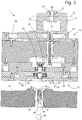
- Figure 1 At the top shows a chuck 1, which can be received on a chuck receptacle 13 shown below, in order to couple the chuck 1 to a drive motor 20 connected to the shaft.
- the chuck 1 has a plurality of clamping jaws 2 on its front side 1v, which can be moved linearly or translationally along a clamping plane E by a spiral ring 3 arranged below the clamping jaws 2.
- the spiral ring 3 engages with a spiral 3s arranged on its surface 3o in corresponding guide grooves 2f of the clamping jaws.
- the clamping jaws 2 are linearly guided by linear guides 4.
- the crown toothing 3k of the spiral ring 3 is part of a purely mechanical gear for transmitting a drive torque of the drive motor 20, which can be coupled with the gear, to the clamping jaws 2. Furthermore, a part of the gear is a splined shaft 5 acting as an output shaft, which is inserted into the Crown teeth 3k of the spiral ring 3 engages in order to set the spiral ring 3 in rotation. The rotation of the spiral ring 3 causes the clamping jaws 2 to be moved uniformly in a translatory manner.
- the splined shaft 5 On the drive side, the splined shaft 5 has a bevel gear 7 and the splined shaft 5 is mounted in a ball bearing 6, which is the ideal way of mounting. Simpler designs provide, for example, friction bearings as bearings.
- the axis of rotation R of the splined shaft 5 lies parallel to the clamping plane E and via a further bevel gear 9 of a drive shaft 8 that engages in the bevel gear 7 of the splined shaft 5, the rotational drive movement is transformed into a longitudinal axis L of the chuck 1, which in the present embodiment is orthogonal to the axis of rotation R. or to the clamping plane E and beyond in the center of the chuck 1, which here coincides with the center Z of the clamping space 21.
- the axis of rotation of the drive shaft 8 coincides with the longitudinal axis L.
- the drive shaft 8 is, in turn, mounted on ball bearings and, on the drive side, has internal toothing 11 which is provided in a bore 12 and is arranged in the interior of the chuck 1.
- the drive shaft 8 ends on the drive side in a recess 24, which serves at least partially as an alignment means 22 for automatic alignment when the chuck 1 is coupled to the drive motor 20 or the chuck receptacle 13.
- an annular run-on bevel 23 is provided which surrounds the drive shaft 8 and acts as an alignment means 22 during coupling with a corresponding, ring-shaped run-on bevel 25 of a projection 26 in the form of a tongue and groove connection.
- a coupling 10 between the chuck 1 and the drive motor 20 or the chuck receptacle 13 not only has the Bore 12 provided internal toothing 11, but also a provided on a coupling element 15 head toothing 16, which are provided on the motor shaft 14.
- the motor shaft 14 also has, in addition to the coupling element 15 and the head toothing 16, a sleeve 17 on which the head toothing 16 is provided and which serves as a coupling element 15.
- a spiral spring 18 is guided in the sleeve 17, against the spring force of which the motor shaft 14 is supported. The maximum movement of the sleeve 17 with respect to the motor shaft 14 is limited by a pin 19 which is guided in an elongated hole 27.
- the motor shaft 14 is driven by the servo motor 20.
- the servomotor 20 thus drives, on the one hand, the motor shaft 14, via the coupling 10, the drive shaft 8 and the splined shaft 5 coupled to it, and thus the spiral ring 3 and the clamping jaws 2.
- current and voltage can be read out continuously via the servo motor, so that if there is resistance to the clamping jaws 2 by a workpiece via the power of the servo motor 20 or the change in the current and / or voltage curve, a control / regulation of the clamping force F after previous calibration of the Servomotor 20 on the chuck I is made possible.
- a servo motor 20 it is also possible to use a drive motor which has mechanical / electrical feedback.
- a chuck 1 'of a vice which has two clamping jaws 2', between the end faces 2s' and the opening width D of the clamping space 21 is formed, in which workpieces can be clamped.
- a translational movement of the clamping jaws 2 'along the clamping plane E takes place via a spindle 32 which, on the output side, translates one of the two clamping jaws 2' as soon as the spindle 32 rotates.
- the spindle 32 is rotated by a chain drive 31 coupled to the spindle 32 on the output side, with the chain drive 31 is driven on the drive side by a shaft 33.
- the shaft 33 is in turn driven by a bevel gear 34 on a gear 35 of the shaft 33.
- the bevel gear 34 is located on the output side on a drive shaft 8 'which, on the drive side, is analogous to that in FIG Figure 1 embodiment shown is formed.
- the chuck receptacle 13 and the drive motor 20 as well as the coupling 10 are designed identically as in the first embodiment.
Landscapes
- Engineering & Computer Science (AREA)
- Mechanical Engineering (AREA)
- Gripping On Spindles (AREA)
Description
- Die vorliegende Erfindung betrifft ein System aus einem Spannfutter zum Einspannen von Werkstücken oder Werkzeugen in einem Einspannraum mit einer Spannkraft F und einem Antriebsmotor.
- Spannfutter dienen in der Werkzeugtechnik, insbesondere beim Drehen und Fräsen zur Aufnahme unterschiedlicher Werkstücke oder Werkzeuge in den von Spannbacken des Spannfutters gebildeten Einspannraum. Werkzeuge können beispielsweise Fräsköpfe oder Bohrer sein, die in Magazinen gelagert und automatisiert aus dem jeweiligen Magazin entnommen und computergesteuert im Spannfutter eingespannt werden, um beispielsweise am gleichen Bauteil unterschiedliche Prozessschritte durchführen zu können.
- Die Druckschrift
JP S52 146776 U - Insbesondere bei nicht hydraulisch oder pneumatisch betriebenen Spannfuttern ist es in regelmäßigen Abständen erforderlich, das Spannfutter auszutauschen, beispielsweise wenn das Spannfutter nicht mehr mit der notwendigen Präzision arbeitet oder die Dimension des Spannfutters nicht für den Einsatz geeignet ist. Im Spannfutter werden Werkzeuge oder Maschinenbauteile oder das zu bearbeitende Werkstück im Zentrum des Drehfutters in einem durch Stirnseiten von Spannbacken des Spannfutters gebildeten Einspannraum zentral eingespannt.
- Dabei haben beispielsweise hydraulische und pneumatische Spannfutter den Vorteil, dass sie automatisch und schnell schaltbar sind. Die mit hydraulischen und pneumatischen Spannfuttern erreichbaren Spannwege der Spannbacken sind vergleichsweise klein, beispielsweise nur +/- 10mm, so dass der kleinste und größte Durchmesser des Einspannraums, der für die Variabilität des Spannfutters steht, begrenzt ist. Allenfalls durch Umsetzen oder Austauschen der Spannbacken kann das Spannfutter größere Werkzeuge oder Werkstücke aufnehmen.
- Dafür ist die erreichbare Spannkraft bei solchen Spannfuttern sehr groß. Um also Werkzeuge oder Werkstücke mit verschiedenen Abmessungen, insbesondere verschiedenem Durchmesser aufnehmen zu können, muss entweder das Spannfutter ausgetauscht oder die Spannbacken versetzt werden.
- Spannfutter sind beispielsweise Spannkopffutter, Bohrfutter, Drehfutter oder Schrumpfspannfutter.
- Darüber hinaus erfolgt das Austauschen der Spannfutter meist manuell, wobei ein Facharbeiter die Werkzeugmaschine anhält, öffnet, und die Backen des Spannfutters öffnet, das Werkstück entfernt und anschließend das Spannfutter gegen ein neues Spannfutter austauscht.
- Es ist daher die Aufgabe der vorliegenden Erfindung, ein Spannfutter vorzusehen, das effizienter einsetzbar ist, insbesondere hohe Spannkraft erreicht, weite Spannwege und gleichzeitig eine möglichst kompakte Bauweise aufweist.
- Das der Erfindung zugrunde liegende technische Problem wird mit den Merkmalen des unabhängigen Anspruchs 1 gelöst. Vorteilhafte Weiterbildungen der Erfindung sind in den Unteransprüchen angegeben. In den Rahmen der Erfindung fallen auch sämtliche Kombinationen aus zumindest zwei von in der Beschreibung, den Ansprüchen und/oder den Figuren angegebenen Merkmalen. Bei angegebenen Wertebereichen sollen auch innerhalb der genannten Grenzen liegende Werte als Grenzwerte offenbart und in beliebiger Kombination beanspruchbar sein.
- Der Erfindung liegt der Gedanke zugrunde, das Spannfutter, insbesondere durch Auslagerung von Kraftmessmitteln und/oder Wegmessmitteln und/oder sonstiger elektrischer Bauteile, die den Zustand des Spannfutters bestimmen, derart vorzusehen, dass das Spannfutter zum einen automatisiert austauschbar ausgebildet ist beziehungsweise ausschließlich zur Übertragung des Antriebsmoments vom Antriebsmotor auf die Spannbacken dient. Zum Austauschen des Spannfutters wird ein Roboterarm eingesetzt. Ein weiterer, alternativ oder kumulativ hierzu vorgesehener Lösungsansatz liegt darin, dass durch ein in das Innere des Spannfutters verlegtes Getriebe und einen daran automatisiert anschließbaren Antriebsmotor allein durch den Antriebsmotor und die vom Antriebsmotor über das Getriebe ausgeführte Bewegung der Spannbacken eine Bewegung von der maximalen Größe des Einspannraums bis zur minimalen Größe des Einspannraums ausführbar ist. Das Spannfutter ist somit flexibler für eine größere Zahl an Werkstücken einsetzbar.
- Insbesondere ist vorgesehen, dass das Getriebe zwischen dem Antriebsmotor und einem unmittelbar die Spannbacken antreibenden Spannbackenantrieb, insbesondere einem Spiralring, rein mechanisch und/oder rein formschlüssig ausgebildet ist. Am Spannbackenantrieb kann zusätzlich für eine Feinverstellung der Spannbacken beziehungsweise jedes Spannbackens zusätzlich ein hydraulischer oder pneumatischer Antrieb vorgesehen sein. Der zusätzliche Antrieb ist insbesondere Vorteilhaft für kleine Stellwege der Spannbacken, während das Getriebe mit seinem Spannbackenantrieb für vergleichsweise große Verstellwege von mindestens 1cm, insbesondere mindestens 2cm, vorzugsweise mindestens 5cm vorgesehen ist.
- Der Einspannraum ist definiert durch die Zahl der Spannbacken und dient zur Aufnahme von Werkstücken und/oder Werkzeugen mit unterschiedlicher Außenkontur in einem Einspannabschnitt der Werkzeuge/Werkstücke. Meist ist der Einspannabschnitt als polygonaler Zylinderabschnitt an einem Einspannende des Werkzeugs/Werkstücks vorgesehen. Die Spannbacken spannen das Werkzeug/Werkstück an der Mantelfläche des Einspannabschnitts ein, indem die Spannbacken mit der durch den Antriebsmotor vorgesehenen Spannkraft F von mindestens zwei, meist drei oder vier Seiten auf die Mantelfläche drücken, wodurch ein Kraftschluss zwischen dem Spannfutter und dem Werkzeug/Werkstück entsteht.
- Erfindungsgemäß ist vorgesehen, dass die Spannbacken entlang der Einspannebene E translatorisch durch einen an jedem Spannbacken, insbesondere integral, vorgesehenen Antrieb, insbesondere Führungsnuten, von einer Maximalposition bis zu einer Minimalposition des Spannbackens an dem jeweiligen Spannfutter bewegbar sind, so dass auf ein Versetzen des Spannbackens, wie es beispielsweise bei hydraulisch oder pneumatisch bewegbaren Spannbacken erforderlich ist, verzichtet werden kann. Die Spannbacken sind also ohne Versetzen über den gesamten, von den Spannbacken am jeweiligen Spannfutter vorgesehenen Spannweg bewegbar.
- Durch die Auslagerung bisher in Spannfuttern implizierter funktionaler Bauteile werden nicht nur die Kosten für das Spannfutter reduziert, sondern die Funktion des Spannfutters auf das Wesentliche reduziert, nämlich das präzise Einspannen und Fixieren von Werkstücken oder Werkzeugen, um es gegen Verschiebung und/oder Rotation zu sichern.
- Die vorliegende Erfindung eignet sich besonders für Dreh- oder Fräsfutter. Von besonderem Vorteil ist es dabei gemäß einer Ausführungsform der Erfindung, wenn das Spannfutter rein mechanisch ausgeführt ist, da dies einerseits die Fertigung des Spannfutters vereinfacht und die Zuverlässigkeit des Spannfutters erhöht.
- Indem eine Öffnungsweite D zwischen mindestens zwei der Spannbacken und die Spannkraft F direkt durch den, insbesondere als Servomotor ausgebildeten, Antriebsmotor einstellbar sind, wird die Steuerung/Regelung des Spannfutters beim Einspannen von Werkstücken oder Werkzeugen unmittelbar vom Antriebsmotor erledigt, ohne dass zusätzliche Sensoren oder Messmittel notwendig wären. Der Antriebsmotor kann dabei insbesondere momentengeregelt und/oder positionsgeregelt sein, wobei eine Kalibrierung des Servomotors und des im Servomotor vorhandenen geschlossenen Regelkreises auf das jeweilige Spannfutter erforderlich ist. Auf diese Weise ist eine besonders einfache, effiziente und sehr genaue Steuerung/Regelung des Spannfutters möglich.
- Gemäß einer vorteilhaften Ausführungsform der Erfindung ist vorgesehen, dass der Einspannraum auf einer Vorderseite des Spannfutters und die Koppelmittel auf einer von der Vorderseite abgewandten Rückseite des Spannfutters vorgesehen sind. Diese Ausgestaltung erleichtert den Wechsel und Einsatz des Spannfutters und ermöglicht eine platzsparende Bauweise.
- Soweit die Koppelmittel eine, insbesondere federnd gelagerte, Keilwelle mit einem an der Rückseite liegenden, formschlüssig wirkenden Koppelelement, insbesondere einer an der Antriebsseite der Keilwelle vorgesehenen Innenverzahnung, zum formschlüssigen Eingriff in ein korrespondierendes Koppelelement einer Motorwelle eines Antriebsmotors aufweist, wird die Kopplung durch Aufsetzen des Spannfutters auf das korrespondierende Koppelelement ermöglicht.
- Gemäß einer weiteren vorteilhaften Ausführungsform der Erfindung ist vorgesehen, dass die Koppelmittel mechanische Ausrichtmittel zur selbsttätigen Ausrichtung beim Koppeln des Spannfutters mit dem Antriebsmotor aufweisen, insbesondere in Form mindestens einer, vorzugsweise einer die Keilwelle umgebenden, insbesondere umfangsgeschlossenen und/oder ringförmigen, Anlaufschräge. Durch diese Maßnahme wird der Kopplungsvorgang sicherer und das Koppelelement sowie das korrespondierende Koppelelement geschont.
- Indem die Motorwelle des Antriebsmotors federnd gelagert ist, kann bei Versatz des Koppelelements mit dem korrespondierenden Koppelelement die Einkopplung nach dem Start des Antriebsmotors erfolgen, indem durch die Bewegung des Antriebs der Versatz zwischen dem Koppelelement und dem korrespondierenden Koppelelement gelöst wird und durch die Federkraft das korrespondierende Koppelelement in das Koppelelement eingreift.
- Erfindungsgemäß ist gemäß einer Ausführungsform außerdem vorgesehen, dass das Getriebe mindestens zwei Wellen mit je einer Antriebs- und einer Abtriebsseite aufweist. Weiterhin ist es mit Vorteil denkbar, dass mindestens zwei der Wellen eine unterschiedlich, insbesondere orthogonal, zueinander ausgerichtete Rotationsrichtung aufweisen. Gemäß einer weiteren Ausführungsform der Erfindung ist es vorgesehen, dass mindestens eine der Wellen, insbesondere die Antriebswelle, zu einer Längsachse L des Spannfutters parallel verläuft, insbesondere mit dieser zusammenfällt.
- Weitere Vorteile, Merkmale und Einzelheiten der Erfindung ergeben sich aus der nachfolgenden Beschreibung bevorzugter Ausführungsbeispiele sowie anhand der Zeichnungen; diese zeigen in:
- Fig. 1
- eine Schnittansicht einer ersten Ausführungsform eines erfindungsgemäßen Spannfutters und einer Spannfutteraufnahme und
- Fig. 2
- eine zweite Ausführungsform eines erfindungsgemäßen Spannfutters und einer Spannfutteraufnahme.
- In den Figuren sind gleiche beziehungsweise gleich wirkende Bauteile mit den gleichen Bezugszeichen versehen.
-
Figur 1 zeigt oben ein Spannfutter 1, das auf einer darunter gezeigten Spannfutteraufnahme 13 aufnehmbar ist, um das Spannfutter 1 mit einem an der Welle angeschlossenen Antriebsmotor 20 zu koppeln. - Das Spannfutter 1 besitzt an seiner Vorderseite 1v mehrere Spannbacken 2, die durch einen unterhalb der Spannbacken 2 angeordneten Spiralring 3 linear beziehungsweise translatorisch entlang einer Einspannebene E bewegbar sind. Der Spiralring 3 greift dabei mit einer an seiner Oberfläche 3o angeordneten Spirale 3s in korrespondierende Führungsnuten 2f der Spannbacken ein. Die Spannbacken 2 sind durch Linearführungen 4 linear geführt.
- An einer Unterseite 3u des Spiralrings 3 befindet sich eine Kronenverzahnung 3k, die sich über den gesamten Umfang des Spiralrings 3 an dessen Unterseite 3u erstreckt. Die Kronenverzahnung 3k des Spiralrings 3 ist Bestandteil eines rein mechanischen Getriebes zur Übertragung eines Antriebsmoments des mit dem Getriebe koppelbaren Antriebsmotors 20 auf die Spannbacken 2. Weiterhin ist Bestandteil des Getriebes eine als Abtriebswelle wirkende Keilwelle 5, die in die Kronenverzahnung 3k des Spiralrings 3 eingreift, um den Spiralring 3 in Rotation zu versetzen. Durch die Rotation des Spiralrings 3 werden die Spannbacken 2 gleichförmig translatorisch bewegt.
- Antriebsseitig weist die Keilwelle 5 ein Kegelzahnrad 7 auf und die Keilwelle 5 ist in einem Kugellager 6 gelagert, was die ideale Lagerungsweise darstellt. Einfachere Ausführungen sehen als Lager beispielsweise Reiblager vor. Die Rotationsachse R der Keilwelle 5 liegt parallel zur Einspannebene E und über ein weiteres, in das Kegelzahnrad 7 der Keilwelle 5 eingreifendes Kegelzahnrad 9 einer Antriebswelle 8 wird die Antriebsdrehbewegung in eine Längsachse L des Spannfutters 1 transformiert, die bei der vorliegenden Ausführungsform orthogonal zur Rotationsachse R beziehungsweise zur Einspannebene E und darüber hinaus im Zentrum des Spannfutters 1 liegt, das hier mit dem Zentrum Z des Einspannraums 21 zusammenfällt. Die Rotationsachse der Antriebswelle 8 fällt mit der Längsachse L zusammen.
- Die Antriebswelle 8 ist wiederum kugelgelagert und weist antriebsseitig eine in einer Bohrung 12 vorgesehene innenverzahnung 11 auf, die im Inneren des Spannfutters 1 angeordnet ist.
- Die Antriebswelle 8 endet antriebsseitig in einer Ausnehmung 24, die zumindest teilweise als Ausrichtmittel 22 zur selbsttätigen Ausrichtung beim Koppeln des Spannfutters 1 mit dem Antriebsmotor 20 beziehungsweise der Spannfutteraufnahme 13 dient. Hierzu ist eine die Antriebswelle 8 umgebende ringförmige Anlaufschräge 23 vorgesehen, die mit einer korrespondierenden, ringförmigen Anlaufschräge 25 eines Vorsprungs 26 in Form einer Nut-Feder-Verbindung als Ausrichtmittel 22 beim Koppeln wirkt.
- Eine Kupplung 10 zwischen dem Spannfutter 1 und dem Antriebsmotor 20 beziehungsweise der Spannfutteraufnahme 13 weist nicht nur die in der Bohrung 12 vorgesehene Innenverzahnung 11, sondern auch eine an einem Koppelelement 15 vorgesehene Kopfverzahnung 16 auf, die an der Motorwelle 14 vorgesehen sind. Die Motorwelle 14 weist als Koppelanschluss weiterhin neben dem Koppelelement 15 und der Kopfverzahnung 16 eine Hülse 17 auf, an der die Kopfverzahnung 16 vorgesehen ist und die als Koppelelement 15 dient. In der Hülse 17 ist eine Spiralfeder 18 geführt, gegen deren Federkraft sich die Motorwelle 14 abstützt. Die maximale Bewegung der Hülse 17 gegenüber der Motorwelle 14 wird durch einen Stift 19 begrenzt, der in einem Langloch 27 geführt ist.
- Die Motorwelle 14 wird durch den Servomotor 20 angetrieben.
- Der Servomotor 20 treibt damit einerseits die Motorwelle 14, über die Kupplung 10, die Antriebswelle 8 und die daran gekoppelte Keilwelle 5 und somit den Spiralring 3 sowie die Spannbacken 2 an. Andererseits kann über den Servomotor kontinuierlich Strom und Spannung ausgelesen werden, so dass bei Widerstand an den Spannbacken 2 durch ein Werkstück über die Leistung des Servomotors 20 beziehungsweise die Änderung der Strom- und/oder Spannungskurve eine Steuerung/Regelung der Spannkraft F nach vorheriger Kalibrierung des Servomotors 20 auf das Spannfutter I ermöglicht wird. Statt eines Servomotors 20 ist auch ein Antriebsmotor verwendbar, der über eine mechanische/elektrische Rückkopplung verfügt.
- In der
Figur 2 ist ein Spannfutter 1' eines Schraubstocks gezeigt, der über zwei Spannbacken 2' verfügt, zwischen deren Stirnseiten 2s' und die Öffnungsweite D der Einspannraum 21 gebildet wird, in dem Werkstücke einspannbar sind. Eine translatorische Bewegung der Spannbacken 2' entlang der Einspannebene E erfolgt über eine Spindel 32, die abtriebsseitig einen der beiden Spannbacken 2' translatorisch bewegt, sobald die Spindel 32 rotiert. Die Rotation der Spindel 32 erfolgt durch einen mit der Spindel 32 gekoppelten Kettentrieb 31 abtriebsseitig, wobei der Kettentrieb 31 antriebsseitig durch eine Welle 33 angetrieben wird. Die Welle 33 wird wiederum durch ein Kegelzahnrad 34 an einem Zahnrad 35 der Welle 33 angetrieben. Das Kegelzahnrad 34 befindet sich abtriebsseitig auf einer Antriebswelle 8', die antriebsseitig analog der inFigur 1 gezeigten Ausführungsform ausgebildet ist. - Die Spannfutteraufnahme 13 und der Antriebsmotor 20 sowie die Kupplung 10 sind identisch wie in der ersten Ausführungsform, ausgebildet.
- Beiden Ausführungsformen gemäß
Figur 1 und2 ist außerdem gemein, dass die Außenkonturen der Spannfutteraufnahme 13 und des Spannfutters 1 fluchten, so dass von außen sofort erkennbar ist, wenn das Spannfutter 1 nicht richtig auf der Spannfutteraufnahme 13 sitzt.Bezugszeichenliste 1, 1' Spannfutter 19 Stift 1v, 1v' Vorderseite 20 Servomotor 1r, 1r' Rückseite 21 Einspannraum 2, 2' Spannbacken 22 Ausrichtmittel 2s, 2s' Stirnseite 23 Anlaufschräge 2f Führungsnuten 24 Ausnehmungen 3 Spiralring 25 Anlaufschräge 30 Oberseite 26 Vorsprung 3k Kronenverzahnung 27 Langloch 3s Spirale 31 Kettentrieb 4 Linearführungen 32 Spindel 5 Keilwelle 33 Welle 6 Kugellager 34 Kegelzahnrad 7 Kegelzahnrad 35 Zahnrad 8, 8' Antriebswelle E Einspannebene 9 Kegelzahnrad F Spannkraft 10 Kupplung D Öffnungsweite 11 Innenverzahnung Z Zentrum 12 Bohrung R Rotationsachse 13 Spannfutteraufnahme L Längsachse 14 Motorwelle 15 Koppelelement 16 Kopfverzahnung 17 Hülse 18 Feder
Claims (9)
- System aus einem Spannfutter (1) zum Einspannen von Werkstücken oder Werkzeugen in einem Einspannraum (21) mit einer Spannkraft (F) und einem Antriebsmotor (20), insbesondere vorgesehen in einer Spannfutteraufnahme (13) zur Aufnahme des Spannfutters (1) und/oder des Antriebsmotors (20), mit:- mindestens zwei translatorisch entlang einer Einspannebene (E) in Richtung eines Zentrums Z des Einspannraums (21) bewegbaren Spannbacken (2), wobei der Einspannraum (21) durch Stirnseiten (2s) der Spannbacken (2) gebildet ist und- einem zumindest überwiegend im Inneren des Spannfutters (1) angeordneten, insbesondere rein mechanischen, vorzugsweise rein formschlüssigen, Getriebe zur Übertragung eines Antriebsmoments eines mit dem Getriebe durch Koppelmittel des Getriebes koppelbaren Antriebsmotors (20) auf die Spannbacken (2) zur Bewegung der Spannbacken (2), wobei der Einspannraum (21) allein durch den Antriebsmotor (20) und die vom Antriebsmotor (20) über das Getriebe ausgeführte Bewegung von der maximalen Größe des Einspannraums (21) bis zur minimalen Größe des Einspannraums (21) verstellbar ist,dadurch gekennzeichnet, dass das System einen Roboterarm zum Austauschen des Spannfutters aufweist, wobei die Koppelmittel automatisiert mit einem korrespondierenden Koppelanschluss des Antriebsmotors (20) koppelbar sind, und wobei eine Öffnungsweite (D) zwischen mindestens zwei der Spannbacken (2) und die Spannkraft (F) direkt durch den Antriebsmotor (20) einstellbar sind.
- System nach Anspruch 1, wobei die, insbesondere rein formschlüssigen Koppelmittel, insbesondere das Spannfutter (1), rein mechanisch ausgeführt sind.
- System nach einem der vorhergehenden Ansprüche, wobei der Antriebsmotor als Servomotor ausgebildet ist.
- System nach Anspruch 3, dadurch gekennzeichnet, dass über den Servomotor kontinuierlich Strom und Spannung auslesbar sind.
- System nach einem der vorhergehenden Ansprüche, dadurch gekennzeichnet, dass der Antriebsmotor momentengeregelt und/oder positionsgeregelt ist.
- System nach einem der vorhergehenden Ansprüche, wobei der Einspannraum (21) auf einer Vorderseite (1v) des Spannfutters (1) und die Koppelmittel auf einer von der Vorderseite (1v) abgewandten Rückseite (1r) des Spannfutters (1) vorgesehen sind.
- System nach einem der vorhergehenden Ansprüche, wobei die Koppelmittel eine, insbesondere federnd gelagerte, Antriebswelle (8) mit einem an der Rückseite (1r) liegenden, formschlüssig wirkenden Koppelelement, insbesondere einer an der Antriebsseite der Antriebswelle (8) vorgesehenen Innenverzahnung (11), zum formschlüssigen Eingriff in ein korrespondierendes Koppelelement (15) einer Motorwelle (14) des Antriebsmotors (20) aufweisen.
- System nach einem der vorhergehenden Ansprüche, wobei die Koppelmittel mechanische Ausrichtmittel zur selbsttätigen Ausrichtung beim Koppeln des Spannfutters (1) mit dem Antriebsmotor (20) aufweisen, insbesondere in Form mindestens einer, vorzugsweise eine die Antriebswelle (8) umgebende, insbesondere umfangsgeschlossene und/oder ringförmige, Anlaufschräge (23).
- System nach Anspruch 1, wobei die Motorwelle (14) federnd gelagert ist.
Applications Claiming Priority (3)
| Application Number | Priority Date | Filing Date | Title |
|---|---|---|---|
| DE102010035150A DE102010035150B4 (de) | 2010-08-23 | 2010-08-23 | Automatisiert koppelbares Spannfutter |
| EP11745757.2A EP2608913B1 (de) | 2010-08-23 | 2011-08-12 | Automatisiert koppelbares spannfutter |
| PCT/EP2011/063896 WO2012025400A1 (de) | 2010-08-23 | 2011-08-12 | Automatisiert koppelbares spannfutter |
Related Parent Applications (2)
| Application Number | Title | Priority Date | Filing Date |
|---|---|---|---|
| EP11745757.2A Division EP2608913B1 (de) | 2010-08-23 | 2011-08-12 | Automatisiert koppelbares spannfutter |
| EP11745757.2A Division-Into EP2608913B1 (de) | 2010-08-23 | 2011-08-12 | Automatisiert koppelbares spannfutter |
Publications (4)
| Publication Number | Publication Date |
|---|---|
| EP2853326A2 EP2853326A2 (de) | 2015-04-01 |
| EP2853326A3 EP2853326A3 (de) | 2015-06-03 |
| EP2853326A8 EP2853326A8 (de) | 2015-08-12 |
| EP2853326B1 true EP2853326B1 (de) | 2021-03-03 |
Family
ID=44630483
Family Applications (3)
| Application Number | Title | Priority Date | Filing Date |
|---|---|---|---|
| EP11745757.2A Active EP2608913B1 (de) | 2010-08-23 | 2011-08-12 | Automatisiert koppelbares spannfutter |
| EP14190524.0A Active EP2853326B1 (de) | 2010-08-23 | 2011-08-12 | Automatisiert koppelbares Spannfutter |
| EP14189516.9A Active EP2853325B1 (de) | 2010-08-23 | 2011-08-12 | System aus einem automatisiert koppelbarem Spannfutter, einem Antriebsmotor und einer Austauscheinrichtung. |
Family Applications Before (1)
| Application Number | Title | Priority Date | Filing Date |
|---|---|---|---|
| EP11745757.2A Active EP2608913B1 (de) | 2010-08-23 | 2011-08-12 | Automatisiert koppelbares spannfutter |
Family Applications After (1)
| Application Number | Title | Priority Date | Filing Date |
|---|---|---|---|
| EP14189516.9A Active EP2853325B1 (de) | 2010-08-23 | 2011-08-12 | System aus einem automatisiert koppelbarem Spannfutter, einem Antriebsmotor und einer Austauscheinrichtung. |
Country Status (7)
| Country | Link |
|---|---|
| US (2) | US9555479B2 (de) |
| EP (3) | EP2608913B1 (de) |
| JP (3) | JP5759002B2 (de) |
| KR (3) | KR101703459B1 (de) |
| CN (3) | CN103153507B (de) |
| DE (1) | DE102010035150B4 (de) |
| WO (1) | WO2012025400A1 (de) |
Families Citing this family (20)
| Publication number | Priority date | Publication date | Assignee | Title |
|---|---|---|---|---|
| DE102010035150B4 (de) * | 2010-08-23 | 2012-03-08 | Ev Group Gmbh | Automatisiert koppelbares Spannfutter |
| EP2700461B1 (de) * | 2012-08-20 | 2016-05-18 | Klingelnberg AG | Vorrichtung zum Einspannen eines Werkzeugs oder eines Werkstücks und Verfahren zum Betätigen einer solchen Spannvorrichtung |
| DE202014004713U1 (de) * | 2014-06-06 | 2015-04-13 | Klingelnberg Ag | Spannsystem für ein Werkstück auf einer Messmaschine |
| DE102015206388B4 (de) * | 2015-04-10 | 2017-06-01 | Aktiebolaget Skf | Vorrichtung zum Halten eines Werkstückes |
| US10044338B2 (en) | 2015-10-15 | 2018-08-07 | Lam Research Corporation | Mutually induced filters |
| DE102015121391A1 (de) * | 2015-12-09 | 2017-06-14 | Röhm Gmbh | Spannmittel |
| JP6687647B2 (ja) * | 2016-02-08 | 2020-04-28 | 株式会社北川鉄工所 | 引き込み型チャック |
| CN106424800B (zh) * | 2016-11-25 | 2018-06-29 | 中国科学院上海技术物理研究所 | 一种用于加工薄型套管状零件的八卡爪内外夹紧装置 |
| CN108127598A (zh) * | 2016-11-30 | 2018-06-08 | 宁波方太厨具有限公司 | 一种同步定位夹紧装置 |
| AT520360B1 (de) * | 2017-08-25 | 2019-10-15 | Dipl Ing Friedrich Moser | Vorrichtung zum Klemmen eines Werkstücks |
| CN108526519A (zh) * | 2018-01-25 | 2018-09-14 | 宁波鄞州启航工业产品设计有限公司 | 一种精密模具制造设备 |
| US10967436B2 (en) * | 2018-02-21 | 2021-04-06 | Navarro IP, LLC | Universal rotating chuck apparatus |
| DE102018106210A1 (de) * | 2018-03-16 | 2019-09-19 | Gressel Ag | Greif- und Positioniereinrichtung zum Transport einer Spannvorrichtung zwischen unterschiedlichen Positionen |
| CN111112665B (zh) * | 2019-12-24 | 2021-08-03 | 洛阳先驱自动化设备有限公司 | 一种车床卡盘 |
| DE102020002319A1 (de) | 2020-04-09 | 2021-10-14 | Michael Weinig Aktiengesellschaft | Spanneinrichtung für Werkstücke aus Holz, Kunststoff, Aluminium und dergleichen sowie Anlage mit einer solchen Spanneinrichtung |
| CN114012122B (zh) * | 2021-11-15 | 2023-01-17 | 无锡职业技术学院 | 一种自动定心四爪单缸液压卡盘 |
| CZ309970B6 (cs) * | 2022-05-09 | 2024-03-13 | v-tech s.r.o. | Pneumatický svěrák pro CNC obráběcí centra |
| JP7581283B2 (ja) | 2022-06-15 | 2024-11-12 | 株式会社日進Fulfil | 被加工物保持具および加工装置 |
| CN117798832B (zh) * | 2024-02-28 | 2024-05-10 | 四川卓皓雅医疗器械有限公司 | 一种牙科种植体喷砂装置及其使用方法 |
| TWI896197B (zh) * | 2024-06-28 | 2025-09-01 | 智茂科技有限公司 | 主軸銑車複合機之轉換裝置 |
Citations (1)
| Publication number | Priority date | Publication date | Assignee | Title |
|---|---|---|---|---|
| EP2103368A1 (de) * | 2008-03-20 | 2009-09-23 | Karl Hiestand | Spanneinrichtung für Werkzeugmaschinen |
Family Cites Families (37)
| Publication number | Priority date | Publication date | Assignee | Title |
|---|---|---|---|---|
| US1595964A (en) * | 1922-05-01 | 1926-08-10 | E Horton & Son Company | Chuck |
| US1831225A (en) * | 1929-09-23 | 1931-11-10 | Fred H Bogart | Chuck closing and opening mechanism |
| BE387350A (de) * | 1931-09-04 | |||
| US2358049A (en) * | 1941-06-07 | 1944-09-12 | Warner Swasey Co | Work gripping device |
| GB555752A (en) * | 1941-06-07 | 1943-09-06 | Warner Swasey Co | Improvements in chucks or the like |
| FR1457653A (fr) * | 1965-09-13 | 1966-01-24 | Mandrin pour machine-outil | |
| JPS52146776U (de) * | 1976-05-01 | 1977-11-07 | ||
| JPS52146776A (en) | 1976-06-02 | 1977-12-06 | Mitsubishi Heavy Ind Ltd | Recovery of sovent vapor |
| US4254676A (en) * | 1977-10-29 | 1981-03-10 | Pratt Burnerd International Limited | Workholding |
| US4550922A (en) * | 1982-08-23 | 1985-11-05 | The S-P Manufacturing Corporation | Workholder |
| ATE30390T1 (de) * | 1982-11-10 | 1987-11-15 | Roehm Guenter H | Kraftbetaetigtes spannfutter. |
| JPS5997884A (ja) * | 1982-11-25 | 1984-06-05 | 豊田工機株式会社 | 交換式ハンドを備えた作業装置 |
| SU1199475A1 (ru) * | 1983-12-26 | 1985-12-23 | Предприятие П/Я В-8336 | Зажимное устройство токарного станка |
| DE3500002A1 (de) * | 1985-01-02 | 1985-08-14 | Lieber, Werkzeugmaschinenfabrik, Inh. Elfriede Lieber, 4990 Lübbecke | Kraftspannfutter 300 mm - 5000 mm (durchmesser) |
| US4647051A (en) | 1985-05-03 | 1987-03-03 | Sheffer Collet Company | Support for a chuck |
| DE3578141D1 (de) | 1985-08-23 | 1990-07-19 | Sp Mfg Corp | Werkzeughalter. |
| SU1463401A1 (ru) * | 1987-05-28 | 1989-03-07 | Предприятие П/Я Р-6930 | Патрон с компенсатором центробежных сил |
| DE3820871A1 (de) * | 1987-06-23 | 1989-02-16 | Gedib Ingenieurbuero U Innovat | Vorrichtung zum fuegen und festspannen von spannmitteln an werkzeugmaschinenspindeln |
| JPH0768984B2 (ja) | 1990-04-13 | 1995-07-26 | トヨタ自動車株式会社 | 手動変速機の同期装置 |
| JP3306108B2 (ja) * | 1992-08-21 | 2002-07-24 | 宇宙開発事業団 | 軸継手機構 |
| JPH1096436A (ja) | 1996-09-24 | 1998-04-14 | Murata Mach Ltd | 動力伝達機構 |
| WO1998036863A1 (en) | 1997-02-21 | 1998-08-27 | Hitachi Seiki Co., Ltd. | Electric chuck for machine tool and method of opening or closing gripping pawl of same |
| JPH11188513A (ja) * | 1997-12-20 | 1999-07-13 | Hitachi Seiki Co Ltd | 工作機械のチャックの自動交換方法及び自動チャック交換装置 |
| WO1999051380A1 (en) * | 1998-04-03 | 1999-10-14 | N.T. Naum Technologies Ltd. | Automatic adjustable power chuck system and method |
| JP3677416B2 (ja) | 1998-10-23 | 2005-08-03 | 株式会社森精機ハイテック | 電動チャックの制御方法および装置 |
| JP4344442B2 (ja) * | 1999-12-17 | 2009-10-14 | 富士機械製造株式会社 | チャック装置 |
| JP2001225215A (ja) * | 2000-02-10 | 2001-08-21 | Mitsubishi Electric Corp | コレットチャック開閉装置および該コレットチャック開閉装置を備えた加工装置 |
| CN1370647A (zh) * | 2001-02-26 | 2002-09-25 | 张和强 | 两级传动式自定心双三爪卡盘 |
| JP4541601B2 (ja) * | 2001-07-19 | 2010-09-08 | 富士機械製造株式会社 | 電動チャックを用いた電気部品装着システム |
| CN100364703C (zh) * | 2006-03-14 | 2008-01-30 | 浙江大学 | 一种夹紧工件或刀具的卡爪 |
| CN201033361Y (zh) * | 2007-04-30 | 2008-03-12 | 浙江三鸥机械股份有限公司 | 一种新型卡盘 |
| JP5098720B2 (ja) * | 2008-03-14 | 2012-12-12 | 村田機械株式会社 | 主軸チャック交換機能付き工作機械 |
| JP2009269091A (ja) * | 2008-04-30 | 2009-11-19 | Murata Mach Ltd | 主軸チャック入換え機構付き工作機械 |
| WO2011008384A1 (en) * | 2009-07-13 | 2011-01-20 | Illinois Tool Works Inc. | Chuck with jaw for workpiece having constant holding force |
| FR2957542B1 (fr) | 2010-03-16 | 2012-05-11 | Commissariat Energie Atomique | Procede d'assemblage de pieces en materiaux a base de sic par brasage non-reactif, compositions de brasure, et joint et assemblage obtenus par ce procede. |
| DE102010035150B4 (de) * | 2010-08-23 | 2012-03-08 | Ev Group Gmbh | Automatisiert koppelbares Spannfutter |
| US9103741B2 (en) | 2010-08-27 | 2015-08-11 | General Electric Company | Methods and systems for assessing residual life of turbomachine airfoils |
-
2010
- 2010-08-23 DE DE102010035150A patent/DE102010035150B4/de active Active
-
2011
- 2011-08-12 CN CN201180040953.5A patent/CN103153507B/zh active Active
- 2011-08-12 CN CN201510495191.8A patent/CN105108190A/zh active Pending
- 2011-08-12 CN CN201510495358.0A patent/CN104999102A/zh active Pending
- 2011-08-12 EP EP11745757.2A patent/EP2608913B1/de active Active
- 2011-08-12 EP EP14190524.0A patent/EP2853326B1/de active Active
- 2011-08-12 KR KR1020157002030A patent/KR101703459B1/ko active Active
- 2011-08-12 KR KR1020157002029A patent/KR101731194B1/ko active Active
- 2011-08-12 US US13/818,414 patent/US9555479B2/en active Active
- 2011-08-12 WO PCT/EP2011/063896 patent/WO2012025400A1/de not_active Ceased
- 2011-08-12 EP EP14189516.9A patent/EP2853325B1/de active Active
- 2011-08-12 JP JP2013525236A patent/JP5759002B2/ja active Active
- 2011-08-12 KR KR1020137003214A patent/KR101533513B1/ko active Active
-
2015
- 2015-04-01 JP JP2015075428A patent/JP5982037B2/ja active Active
- 2015-04-01 JP JP2015075427A patent/JP6021984B2/ja active Active
-
2016
- 2016-12-19 US US15/382,995 patent/US9925597B2/en active Active
Patent Citations (1)
| Publication number | Priority date | Publication date | Assignee | Title |
|---|---|---|---|---|
| EP2103368A1 (de) * | 2008-03-20 | 2009-09-23 | Karl Hiestand | Spanneinrichtung für Werkzeugmaschinen |
Also Published As
| Publication number | Publication date |
|---|---|
| JP5759002B2 (ja) | 2015-08-05 |
| US20130154206A1 (en) | 2013-06-20 |
| EP2853326A8 (de) | 2015-08-12 |
| JP2015120243A (ja) | 2015-07-02 |
| EP2853325A3 (de) | 2015-06-17 |
| KR101533513B1 (ko) | 2015-07-02 |
| US9925597B2 (en) | 2018-03-27 |
| JP6021984B2 (ja) | 2016-11-09 |
| CN104999102A (zh) | 2015-10-28 |
| DE102010035150B4 (de) | 2012-03-08 |
| KR101703459B1 (ko) | 2017-02-06 |
| KR101731194B1 (ko) | 2017-04-27 |
| KR20150017773A (ko) | 2015-02-17 |
| CN105108190A (zh) | 2015-12-02 |
| WO2012025400A1 (de) | 2012-03-01 |
| EP2853326A2 (de) | 2015-04-01 |
| EP2853325A2 (de) | 2015-04-01 |
| EP2853325B1 (de) | 2019-12-18 |
| JP2015120242A (ja) | 2015-07-02 |
| JP2013536096A (ja) | 2013-09-19 |
| JP5982037B2 (ja) | 2016-08-31 |
| US9555479B2 (en) | 2017-01-31 |
| US20170100780A1 (en) | 2017-04-13 |
| DE102010035150A1 (de) | 2012-02-23 |
| KR20130061716A (ko) | 2013-06-11 |
| CN103153507B (zh) | 2015-11-25 |
| EP2608913A1 (de) | 2013-07-03 |
| EP2608913B1 (de) | 2017-07-05 |
| CN103153507A (zh) | 2013-06-12 |
| KR20150014539A (ko) | 2015-02-06 |
| EP2853326A3 (de) | 2015-06-03 |
Similar Documents
| Publication | Publication Date | Title |
|---|---|---|
| EP2853325B1 (de) | System aus einem automatisiert koppelbarem Spannfutter, einem Antriebsmotor und einer Austauscheinrichtung. | |
| EP3741502B1 (de) | Nullpunkt-spannvorrichtung | |
| EP3760352A1 (de) | Ausgleichsspannfutter zum spannen von werkstücken für bearbeitungszentren | |
| DE2167082B1 (de) | Bohrkopf mit einer Vorrichtung zum Verschieben mindestens eines Schneideinsatzes in einem drehbaren Schneidwerkzeugtraeger | |
| DE102021117229B4 (de) | Spannvorrichtung und Verfahren zur Handhabung eines Werkstücks | |
| EP3266546B1 (de) | Spanneinheit | |
| WO1996027468A1 (de) | Positionierantrieb, insbesondere für den einsatz in maschinenwerkzeugen sowie werkzeugkopf mit einem solchen positionierantrieb | |
| EP2158998B1 (de) | Werkzeugrevolver | |
| EP1997582B1 (de) | Verfahren zum Eichen eines Aufspanntisches | |
| EP2363253B1 (de) | Spanner oder -greifer | |
| EP3059036A1 (de) | Spannfutter mit elektromotoren | |
| DE202011001868U1 (de) | Werkzeugwechsler | |
| DE102011076213B4 (de) | Werkzeug mit Zustelleinrichtung und Kraftmesseinrichtung für ein Bearbeitungszentrum sowie Verfahren zum Bearbeiten einer Bohrung | |
| EP4263133B1 (de) | Aufnahmeflansch für einen werkzeugkörper | |
| DE102009034275A1 (de) | Verfahren und Vorrichtung zum Wechseln von Fräsern an einem Industrieroboter | |
| WO2013164270A1 (de) | Auswuchtadapter | |
| DE102012104392A1 (de) | Werkzeughalter für ein Werkzeug zum Entgraten und Anfasen | |
| EP2777848B1 (de) | Spann- oder Greifeinrichtung | |
| DE3634018C2 (de) | ||
| DE3528437C2 (de) | ||
| EP2691201B1 (de) | Buchsenausrichtvorrichtungen für stangenlademagazine und verfahren zur ausrichtung von buchsen mittels solchen buchsenausrichtvorrichtungen | |
| DE102016104904B4 (de) | Werkzeugaufnahme für ein Mess- und/oder Einstellgerät zur Einstellung und/oder Vermessung von Aussteuerwerkzeugen | |
| DE19722229B4 (de) | Mehrstufige Schmiedemaschine mit einer Mehrzahl von justierbaren Umformstufen | |
| EP3292932A1 (de) | Federanordnung zur erzeugung der einzugskraft einer spannvorrichtung und spannvorrichtung mit einer derartigen federanordnung | |
| DE102017104666A1 (de) | Wechselwerkzeugsystem |
Legal Events
| Date | Code | Title | Description |
|---|---|---|---|
| PUAI | Public reference made under article 153(3) epc to a published international application that has entered the european phase |
Free format text: ORIGINAL CODE: 0009012 |
|
| 17P | Request for examination filed |
Effective date: 20141027 |
|
| AC | Divisional application: reference to earlier application |
Ref document number: 2608913 Country of ref document: EP Kind code of ref document: P |
|
| AK | Designated contracting states |
Kind code of ref document: A2 Designated state(s): AL AT BE BG CH CY CZ DE DK EE ES FI FR GB GR HR HU IE IS IT LI LT LU LV MC MK MT NL NO PL PT RO RS SE SI SK SM TR |
|
| PUAL | Search report despatched |
Free format text: ORIGINAL CODE: 0009013 |
|
| AK | Designated contracting states |
Kind code of ref document: A3 Designated state(s): AL AT BE BG CH CY CZ DE DK EE ES FI FR GB GR HR HU IE IS IT LI LT LU LV MC MK MT NL NO PL PT RO RS SE SI SK SM TR |
|
| RIC1 | Information provided on ipc code assigned before grant |
Ipc: B23B 31/163 20060101AFI20150430BHEP |
|
| RAP1 | Party data changed (applicant data changed or rights of an application transferred) |
Owner name: EV GROUP GMBH |
|
| R17P | Request for examination filed (corrected) |
Effective date: 20150821 |
|
| RBV | Designated contracting states (corrected) |
Designated state(s): AL AT BE BG CH CY CZ DE DK EE ES FI FR GB GR HR HU IE IS IT LI LT LU LV MC MK MT NL NO PL PT RO RS SE SI SK SM TR |
|
| STAA | Information on the status of an ep patent application or granted ep patent |
Free format text: STATUS: EXAMINATION IS IN PROGRESS |
|
| 17Q | First examination report despatched |
Effective date: 20200205 |
|
| GRAP | Despatch of communication of intention to grant a patent |
Free format text: ORIGINAL CODE: EPIDOSNIGR1 |
|
| STAA | Information on the status of an ep patent application or granted ep patent |
Free format text: STATUS: GRANT OF PATENT IS INTENDED |
|
| INTG | Intention to grant announced |
Effective date: 20201103 |
|
| GRAS | Grant fee paid |
Free format text: ORIGINAL CODE: EPIDOSNIGR3 |
|
| GRAA | (expected) grant |
Free format text: ORIGINAL CODE: 0009210 |
|
| STAA | Information on the status of an ep patent application or granted ep patent |
Free format text: STATUS: THE PATENT HAS BEEN GRANTED |
|
| AC | Divisional application: reference to earlier application |
Ref document number: 2608913 Country of ref document: EP Kind code of ref document: P |
|
| AK | Designated contracting states |
Kind code of ref document: B1 Designated state(s): AL AT BE BG CH CY CZ DE DK EE ES FI FR GB GR HR HU IE IS IT LI LT LU LV MC MK MT NL NO PL PT RO RS SE SI SK SM TR |
|
| REG | Reference to a national code |
Ref country code: GB Ref legal event code: FG4D Free format text: NOT ENGLISH |
|
| REG | Reference to a national code |
Ref country code: AT Ref legal event code: REF Ref document number: 1366661 Country of ref document: AT Kind code of ref document: T Effective date: 20210315 Ref country code: CH Ref legal event code: EP |
|
| REG | Reference to a national code |
Ref country code: DE Ref legal event code: R096 Ref document number: 502011017076 Country of ref document: DE |
|
| REG | Reference to a national code |
Ref country code: IE Ref legal event code: FG4D Free format text: LANGUAGE OF EP DOCUMENT: GERMAN |
|
| REG | Reference to a national code |
Ref country code: LT Ref legal event code: MG9D |
|
| PG25 | Lapsed in a contracting state [announced via postgrant information from national office to epo] |
Ref country code: HR Free format text: LAPSE BECAUSE OF FAILURE TO SUBMIT A TRANSLATION OF THE DESCRIPTION OR TO PAY THE FEE WITHIN THE PRESCRIBED TIME-LIMIT Effective date: 20210303 Ref country code: GR Free format text: LAPSE BECAUSE OF FAILURE TO SUBMIT A TRANSLATION OF THE DESCRIPTION OR TO PAY THE FEE WITHIN THE PRESCRIBED TIME-LIMIT Effective date: 20210604 Ref country code: FI Free format text: LAPSE BECAUSE OF FAILURE TO SUBMIT A TRANSLATION OF THE DESCRIPTION OR TO PAY THE FEE WITHIN THE PRESCRIBED TIME-LIMIT Effective date: 20210303 Ref country code: LT Free format text: LAPSE BECAUSE OF FAILURE TO SUBMIT A TRANSLATION OF THE DESCRIPTION OR TO PAY THE FEE WITHIN THE PRESCRIBED TIME-LIMIT Effective date: 20210303 Ref country code: BG Free format text: LAPSE BECAUSE OF FAILURE TO SUBMIT A TRANSLATION OF THE DESCRIPTION OR TO PAY THE FEE WITHIN THE PRESCRIBED TIME-LIMIT Effective date: 20210603 Ref country code: NO Free format text: LAPSE BECAUSE OF FAILURE TO SUBMIT A TRANSLATION OF THE DESCRIPTION OR TO PAY THE FEE WITHIN THE PRESCRIBED TIME-LIMIT Effective date: 20210603 |
|
| REG | Reference to a national code |
Ref country code: NL Ref legal event code: MP Effective date: 20210303 |
|
| PG25 | Lapsed in a contracting state [announced via postgrant information from national office to epo] |
Ref country code: PL Free format text: LAPSE BECAUSE OF FAILURE TO SUBMIT A TRANSLATION OF THE DESCRIPTION OR TO PAY THE FEE WITHIN THE PRESCRIBED TIME-LIMIT Effective date: 20210303 Ref country code: LV Free format text: LAPSE BECAUSE OF FAILURE TO SUBMIT A TRANSLATION OF THE DESCRIPTION OR TO PAY THE FEE WITHIN THE PRESCRIBED TIME-LIMIT Effective date: 20210303 Ref country code: RS Free format text: LAPSE BECAUSE OF FAILURE TO SUBMIT A TRANSLATION OF THE DESCRIPTION OR TO PAY THE FEE WITHIN THE PRESCRIBED TIME-LIMIT Effective date: 20210303 Ref country code: SE Free format text: LAPSE BECAUSE OF FAILURE TO SUBMIT A TRANSLATION OF THE DESCRIPTION OR TO PAY THE FEE WITHIN THE PRESCRIBED TIME-LIMIT Effective date: 20210303 |
|
| PG25 | Lapsed in a contracting state [announced via postgrant information from national office to epo] |
Ref country code: NL Free format text: LAPSE BECAUSE OF FAILURE TO SUBMIT A TRANSLATION OF THE DESCRIPTION OR TO PAY THE FEE WITHIN THE PRESCRIBED TIME-LIMIT Effective date: 20210303 |
|
| PG25 | Lapsed in a contracting state [announced via postgrant information from national office to epo] |
Ref country code: CZ Free format text: LAPSE BECAUSE OF FAILURE TO SUBMIT A TRANSLATION OF THE DESCRIPTION OR TO PAY THE FEE WITHIN THE PRESCRIBED TIME-LIMIT Effective date: 20210303 Ref country code: EE Free format text: LAPSE BECAUSE OF FAILURE TO SUBMIT A TRANSLATION OF THE DESCRIPTION OR TO PAY THE FEE WITHIN THE PRESCRIBED TIME-LIMIT Effective date: 20210303 Ref country code: SM Free format text: LAPSE BECAUSE OF FAILURE TO SUBMIT A TRANSLATION OF THE DESCRIPTION OR TO PAY THE FEE WITHIN THE PRESCRIBED TIME-LIMIT Effective date: 20210303 |
|
| PG25 | Lapsed in a contracting state [announced via postgrant information from national office to epo] |
Ref country code: IS Free format text: LAPSE BECAUSE OF FAILURE TO SUBMIT A TRANSLATION OF THE DESCRIPTION OR TO PAY THE FEE WITHIN THE PRESCRIBED TIME-LIMIT Effective date: 20210703 Ref country code: SK Free format text: LAPSE BECAUSE OF FAILURE TO SUBMIT A TRANSLATION OF THE DESCRIPTION OR TO PAY THE FEE WITHIN THE PRESCRIBED TIME-LIMIT Effective date: 20210303 Ref country code: RO Free format text: LAPSE BECAUSE OF FAILURE TO SUBMIT A TRANSLATION OF THE DESCRIPTION OR TO PAY THE FEE WITHIN THE PRESCRIBED TIME-LIMIT Effective date: 20210303 Ref country code: PT Free format text: LAPSE BECAUSE OF FAILURE TO SUBMIT A TRANSLATION OF THE DESCRIPTION OR TO PAY THE FEE WITHIN THE PRESCRIBED TIME-LIMIT Effective date: 20210705 Ref country code: ES Free format text: LAPSE BECAUSE OF FAILURE TO SUBMIT A TRANSLATION OF THE DESCRIPTION OR TO PAY THE FEE WITHIN THE PRESCRIBED TIME-LIMIT Effective date: 20210303 |
|
| REG | Reference to a national code |
Ref country code: DE Ref legal event code: R097 Ref document number: 502011017076 Country of ref document: DE |
|
| PLBE | No opposition filed within time limit |
Free format text: ORIGINAL CODE: 0009261 |
|
| STAA | Information on the status of an ep patent application or granted ep patent |
Free format text: STATUS: NO OPPOSITION FILED WITHIN TIME LIMIT |
|
| PG25 | Lapsed in a contracting state [announced via postgrant information from national office to epo] |
Ref country code: AL Free format text: LAPSE BECAUSE OF FAILURE TO SUBMIT A TRANSLATION OF THE DESCRIPTION OR TO PAY THE FEE WITHIN THE PRESCRIBED TIME-LIMIT Effective date: 20210303 Ref country code: DK Free format text: LAPSE BECAUSE OF FAILURE TO SUBMIT A TRANSLATION OF THE DESCRIPTION OR TO PAY THE FEE WITHIN THE PRESCRIBED TIME-LIMIT Effective date: 20210303 |
|
| 26N | No opposition filed |
Effective date: 20211206 |
|
| PG25 | Lapsed in a contracting state [announced via postgrant information from national office to epo] |
Ref country code: SI Free format text: LAPSE BECAUSE OF FAILURE TO SUBMIT A TRANSLATION OF THE DESCRIPTION OR TO PAY THE FEE WITHIN THE PRESCRIBED TIME-LIMIT Effective date: 20210303 |
|
| REG | Reference to a national code |
Ref country code: CH Ref legal event code: PL |
|
| PG25 | Lapsed in a contracting state [announced via postgrant information from national office to epo] |
Ref country code: MC Free format text: LAPSE BECAUSE OF FAILURE TO SUBMIT A TRANSLATION OF THE DESCRIPTION OR TO PAY THE FEE WITHIN THE PRESCRIBED TIME-LIMIT Effective date: 20210303 |
|
| REG | Reference to a national code |
Ref country code: BE Ref legal event code: MM Effective date: 20210831 |
|
| GBPC | Gb: european patent ceased through non-payment of renewal fee |
Effective date: 20210812 |
|
| PG25 | Lapsed in a contracting state [announced via postgrant information from national office to epo] |
Ref country code: LI Free format text: LAPSE BECAUSE OF NON-PAYMENT OF DUE FEES Effective date: 20210831 Ref country code: CH Free format text: LAPSE BECAUSE OF NON-PAYMENT OF DUE FEES Effective date: 20210831 |
|
| PG25 | Lapsed in a contracting state [announced via postgrant information from national office to epo] |
Ref country code: IS Free format text: LAPSE BECAUSE OF FAILURE TO SUBMIT A TRANSLATION OF THE DESCRIPTION OR TO PAY THE FEE WITHIN THE PRESCRIBED TIME-LIMIT Effective date: 20210703 Ref country code: LU Free format text: LAPSE BECAUSE OF NON-PAYMENT OF DUE FEES Effective date: 20210812 |
|
| PG25 | Lapsed in a contracting state [announced via postgrant information from national office to epo] |
Ref country code: IE Free format text: LAPSE BECAUSE OF NON-PAYMENT OF DUE FEES Effective date: 20210812 Ref country code: GB Free format text: LAPSE BECAUSE OF NON-PAYMENT OF DUE FEES Effective date: 20210812 Ref country code: FR Free format text: LAPSE BECAUSE OF NON-PAYMENT OF DUE FEES Effective date: 20210831 Ref country code: BE Free format text: LAPSE BECAUSE OF NON-PAYMENT OF DUE FEES Effective date: 20210831 |
|
| PG25 | Lapsed in a contracting state [announced via postgrant information from national office to epo] |
Ref country code: HU Free format text: LAPSE BECAUSE OF FAILURE TO SUBMIT A TRANSLATION OF THE DESCRIPTION OR TO PAY THE FEE WITHIN THE PRESCRIBED TIME-LIMIT; INVALID AB INITIO Effective date: 20110812 Ref country code: CY Free format text: LAPSE BECAUSE OF FAILURE TO SUBMIT A TRANSLATION OF THE DESCRIPTION OR TO PAY THE FEE WITHIN THE PRESCRIBED TIME-LIMIT Effective date: 20210303 |
|
| PG25 | Lapsed in a contracting state [announced via postgrant information from national office to epo] |
Ref country code: MK Free format text: LAPSE BECAUSE OF FAILURE TO SUBMIT A TRANSLATION OF THE DESCRIPTION OR TO PAY THE FEE WITHIN THE PRESCRIBED TIME-LIMIT Effective date: 20210303 |
|
| PG25 | Lapsed in a contracting state [announced via postgrant information from national office to epo] |
Ref country code: TR Free format text: LAPSE BECAUSE OF FAILURE TO SUBMIT A TRANSLATION OF THE DESCRIPTION OR TO PAY THE FEE WITHIN THE PRESCRIBED TIME-LIMIT Effective date: 20210303 |
|
| PG25 | Lapsed in a contracting state [announced via postgrant information from national office to epo] |
Ref country code: MT Free format text: LAPSE BECAUSE OF FAILURE TO SUBMIT A TRANSLATION OF THE DESCRIPTION OR TO PAY THE FEE WITHIN THE PRESCRIBED TIME-LIMIT Effective date: 20210303 |
|
| PGFP | Annual fee paid to national office [announced via postgrant information from national office to epo] |
Ref country code: DE Payment date: 20250819 Year of fee payment: 15 |
|
| PGFP | Annual fee paid to national office [announced via postgrant information from national office to epo] |
Ref country code: IT Payment date: 20250829 Year of fee payment: 15 |
|
| PGFP | Annual fee paid to national office [announced via postgrant information from national office to epo] |
Ref country code: AT Payment date: 20250819 Year of fee payment: 15 |