EP2853285B1 - Multi-frequency neural treatments and associated systems - Google Patents
Multi-frequency neural treatments and associated systems Download PDFInfo
- Publication number
- EP2853285B1 EP2853285B1 EP14178370.4A EP14178370A EP2853285B1 EP 2853285 B1 EP2853285 B1 EP 2853285B1 EP 14178370 A EP14178370 A EP 14178370A EP 2853285 B1 EP2853285 B1 EP 2853285B1
- Authority
- EP
- European Patent Office
- Prior art keywords
- signal
- therapy
- patient
- dorsal
- frequency
- Prior art date
- Legal status (The legal status is an assumption and is not a legal conclusion. Google has not performed a legal analysis and makes no representation as to the accuracy of the status listed.)
- Revoked
Links
- 0 CCCCC(C(C)C)C(C(CC(CC*C)C1)*(CC)*C)C1(C)C1CCC1 Chemical compound CCCCC(C(C)C)C(C(CC(CC*C)C1)*(CC)*C)C1(C)C1CCC1 0.000 description 3
Images


Classifications
-
- A—HUMAN NECESSITIES
- A61—MEDICAL OR VETERINARY SCIENCE; HYGIENE
- A61N—ELECTROTHERAPY; MAGNETOTHERAPY; RADIATION THERAPY; ULTRASOUND THERAPY
- A61N1/00—Electrotherapy; Circuits therefor
- A61N1/02—Details
- A61N1/04—Electrodes
- A61N1/05—Electrodes for implantation or insertion into the body, e.g. heart electrode
- A61N1/0551—Spinal or peripheral nerve electrodes
-
- A—HUMAN NECESSITIES
- A61—MEDICAL OR VETERINARY SCIENCE; HYGIENE
- A61N—ELECTROTHERAPY; MAGNETOTHERAPY; RADIATION THERAPY; ULTRASOUND THERAPY
- A61N1/00—Electrotherapy; Circuits therefor
- A61N1/18—Applying electric currents by contact electrodes
- A61N1/32—Applying electric currents by contact electrodes alternating or intermittent currents
- A61N1/36—Applying electric currents by contact electrodes alternating or intermittent currents for stimulation
- A61N1/3605—Implantable neurostimulators for stimulating central or peripheral nerve system
- A61N1/3606—Implantable neurostimulators for stimulating central or peripheral nerve system adapted for a particular treatment
- A61N1/36071—Pain
-
- A—HUMAN NECESSITIES
- A61—MEDICAL OR VETERINARY SCIENCE; HYGIENE
- A61N—ELECTROTHERAPY; MAGNETOTHERAPY; RADIATION THERAPY; ULTRASOUND THERAPY
- A61N1/00—Electrotherapy; Circuits therefor
- A61N1/18—Applying electric currents by contact electrodes
- A61N1/32—Applying electric currents by contact electrodes alternating or intermittent currents
- A61N1/36—Applying electric currents by contact electrodes alternating or intermittent currents for stimulation
- A61N1/3605—Implantable neurostimulators for stimulating central or peripheral nerve system
- A61N1/36128—Control systems
- A61N1/36146—Control systems specified by the stimulation parameters
- A61N1/36167—Timing, e.g. stimulation onset
- A61N1/36171—Frequency
-
- A—HUMAN NECESSITIES
- A61—MEDICAL OR VETERINARY SCIENCE; HYGIENE
- A61N—ELECTROTHERAPY; MAGNETOTHERAPY; RADIATION THERAPY; ULTRASOUND THERAPY
- A61N1/00—Electrotherapy; Circuits therefor
- A61N1/18—Applying electric currents by contact electrodes
- A61N1/32—Applying electric currents by contact electrodes alternating or intermittent currents
- A61N1/36—Applying electric currents by contact electrodes alternating or intermittent currents for stimulation
- A61N1/372—Arrangements in connection with the implantation of stimulators
- A61N1/378—Electrical supply
- A61N1/3787—Electrical supply from an external energy source
Definitions
- the present disclosure relates generally to methods and apparatuses for treating patient conditions, including chronic pain conditions via techniques that can include stimulating and blocking neuronal tissue associated with the spinal cord.
- Stimulation signal parameters e.g., pulse width, frequency, and amplitude
- an organ e.g., brain or stomach
- Down-regulating signals also can be applied to nerve fibers. Certain signal parameters can result in a signal that inhibits the nerve or blocks the propagation of action potentials along the nerve.
- the nerve conduction block is applied to nerves with down-regulating signals selected to block the entire cross-section or part of the cross section of the nerves (e.g., afferent, efferent, myelinated, and non-myelinated fibers) at the site where the down-regulating signal is applied.
- down-regulating signals are used to manage motor control over certain areas of a patient's body.
- cryogenic nerve blocking of the vagus nerve to control motor activity is described in Dapoigny et al., "Vagal influence on colonic motor activity in conscious nonhuman primates," Am. J. Physiol., 262: G231 - G236 (1992 ).
- a cryogenic vagal block and the resulting effect on gastric emptying are described in Paterson CA, et al., "Determinants of Occurrence and Volume of Transpyloric Flow During Gastric Emptying of Liquids in Dogs: Importance of Vagal Input," Dig Dis Sci, (2000); 45:1509-1516 .
- applying up-regulating electrical pulses to the spinal cord associated with regions of the body (e.g., dermatomes) afflicted with chronic pain can induce paresthesia, or a subjective sensation of numbness or tingling, in the afflicted bodily regions. This paresthesia can effectively mask the non-acute pain sensations perceived at the brain.
- Motor spinal nervous tissue e.g., nervous tissue from ventral nerve roots
- Sensory spinal nervous tissue e.g., nervous tissue from dorsal nerve roots
- Corresponding dorsal and ventral nerve roots depart the spinal cord "separately.” Laterally from the spinal cord, the nervous tissue of the dorsal and ventral nerve roots are mixed, or intertwined. Accordingly, electrical stimulation intended to manage and control one condition (e.g., pain) can inadvertently interfere with nerve transmission pathways in adjacent nervous tissue (e.g., motor nerves).
- one condition e.g., pain
- nerve transmission pathways in adjacent nervous tissue e.g., motor nerves
- Electrodes positioned on the dorsal column external to the dura layer surrounding a spinal cord.
- the electrodes are typically carried by a percutaneous lead, although a laminotomy lead also can be used.
- Percutaneous leads commonly have two or more electrodes and are positioned within an epidural space through the use of an insertion, or Touhy-like, needle.
- An example of an eight-electrode percutaneous lead is an OCTRODE® lead manufactured by Advanced Neuromodulation Systems, Inc. of Plano, Texas.
- the insertion needle is passed through the skin, between the desired vertebrae, and into an epidural space located between a dural layer and the surrounding vertebrae.
- Laminotomy leads generally have a wider, paddle-like shape, and are inserted via an incision rather than through a needle. For example, a small incision is made in the back of a patient to access the space between the dura and the surrounding vertebrae.
- the potential paresthesia coverage will strongly differ, however, depending on whether DC fibers or DR fibers are stimulated.
- the fibers corresponding to all dermatomes from the sacral ones up to the electrode level may be activated, thus resulting in broad paresthesia coverage.
- stimulating DR fibers the fibers will be activated in a limited number of rootlets close to the cathodal contact(s), thereby resulting in a paresthesia effect confined to one or two dermatomes at each body side.
- SCS Spinal Cord Stimulation
- US2007/0150034 discloses a system including an implantable medical device (IMD) that delivers stimulation via an implantable medical lead.
- IMD implantable medical device
- the lead may be implanted within or between intra-dermal, deep dermal, or subcutaneous tissue layers, and may be used to, for example, deliver peripheral nerve field stimulation (PNFS) to treat pain experienced by the patient at the site at which the lead is implanted.
- PNFS peripheral nerve field stimulation
- Other types of therapy may be delivered in combination with PNFS, including spinal cord stimulation (SCS).
- SCS spinal cord stimulation
- the IMD delivers low frequency pulses at a frequency of 50 Hz and amplitude of 3 volts or 2 volts, or at a frequency of 40 Hz and amplitude of 4.8 volts, or at a frequency of 240 Hz and 2 volts.
- US2006/0116742 discloses a system and method for treating auditory dysfunction by somato sensory system stimulation.
- the system comprises a probe and a device to stimulate the probe.
- the probe has a stimulation portion subcutaneously implanted in communication with a predetermined spinal cord site.
- the stimulation portion of the probe may be implanted externally to the spinal cord, or may be implanted epidurally.
- the stimulation portion may be a medical lead.
- the system delivers low frequency signals.
- the system uses an amplitude in the range of about 2 mA to 100 mA and a frequency in the range of about 3 Hz to about 80 Hz.
- the frequency ranges from about 1 Hz to 300 Hz, where each spike can comprise a frequency in the range of about 50 Hz to about 1000 Hz.
- low frequency signals are applied to the dorsal column to address chronic patient pain associated with a peripheral site.
- the dorsal roots also can be stimulated when low frequency stimulation is applied to the dorsal column to produce the paresthesia necessary to overcome the chronic pain.
- the dorsal roots may be stimulated if the stimulation leads are placed too close to the dorsal root, and/or if the amplitude of the low frequency signal is increased to the discomfort threshold.
- the discomfort threshold at the dorsal root can be reached before the parethesia threshold (i.e., the threshold at which paresthesia is affected) is reached at the dorsal column.
- the clinician has limited freedom to increase the amplitude of the signal at the dorsal column to achieve the desired paresthesia effect, before discomfort is felt due to the dorsal root stimulation.
- aspects of the present disclosure are directed to managing chronic pain through the application of electrical energy to selected nervous tissue and, in particular embodiments, to methods and systems for treating chronic pain by applying neuromodulation therapies to one or more regions of neuronal tissue in the spinal region.
- the "spinal region” includes the nerves of the dorsal column, dorsal roots, and the dorsal roots ganglion, which are located within the dural layer.
- a method for treating patient pain in accordance with a particular embodiment of the disclosure includes applying a first electrical signals to a first target location (e.g., a dorsal column) of the patient's spinal cord region at a frequency in a first frequency range of up to about 1,500 Hz.
- the method further includes applying a second electrical signal to a second target location (e.g., at least one of a dorsal root and a dorsal root ganglion) of the patient's spinal cord region at a frequency in a second frequency range of from about 2,500 Hz to about 100,000 Hz.
- the second frequency range can be from about 2,500 Hz to about 20,000 Hz, or about 3,000 Hz to about 10,000 Hz.
- Further embodiments of the disclosure include inducing paresthesia by applying the first electrical signal, and at least partially blocking patient discomfort resulting from applying the first electrical signal by applying the second electrical signal.
- a method in accordance with another embodiment of the disclosure includes implanting a first electrode proximate to a dorsal column of the patient's spinal cord region, and implanting a second electrode proximate to at least one of a dorsal root and a dorsal root ganglion of the patient's spinal cord region.
- the method can further include applying a first electrical signal to the first electrode at a frequency in a first frequency range of up to about 1,500 Hz. If the patient experiences discomfort, a second electrical signal is applied to the second electrode at a frequency in a second frequency range of from about 2,500 Hz to about 100,000 Hz in combination with applying the first electrical signal, and without repositioning the first electrode.
- the second frequency range can be from about 2,500 Hz to about 20,000 Hz, or about 3,000 Hz to about 10,000 Hz.
- the system can include a controller having instructions for directing first electrical signals in a first frequency range of up to about 1,500 Hz, and directing second electrical signals in a second frequency range of from about 2,500 Hz to about 100,000 Hz.
- the second frequency range can be from about 2,500 Hz to about 20,000 Hz, or about 3,000 Hz to about 10,000 Hz.
- a first electrical signal delivery device can be electrically coupled to the controller to receive the first electrical signals, and can be configured to be positioned proximate to a first target location of the patient's spinal cord region (e.g., the dorsal column).
- a second electrical signal delivery device can be electrically coupled to the controller to receive the second electrical signals, and can be configured to be positioned proximate to a second target location of the patient's spinal cord region (e.g., at least one of a dorsal root and a dorsal root ganglion of the patient's spinal cord region).
- a second target location of the patient's spinal cord region e.g., at least one of a dorsal root and a dorsal root ganglion of the patient's spinal cord region.
- Figure 1 schematically illustrates a representative therapy system 100 for providing relief from chronic pain, arranged relative to the general anatomy of a spinal cord SC of a patient.
- the therapy system 100 can include a controller (e.g., a pulse generator 101) implanted subcutaneously within the patient.
- the pulse generator 101 is attached via a lead body 102 to an electrode array 103 or other signal delivery device, which is implanted in close proximity to the spinal cord SC.
- the electrode array 103 can include multiple electrodes or electrode contacts carried by a support substrate.
- the pulse generator 101 or other controller transmits instructions and power to the electrode array 103 via the lead body 102 to apply therapy signals (e.g., electrical impulses) to the nerve fibers of the patient to up-regulate (e.g., stimulate) and/or down-regulate (e.g., block or partially block) the nerves.
- therapy signals e.g., electrical impulses
- the pulse generator 101 can include a computer-readable medium containing the instructions.
- the pulse generator 101 and/or other elements of the system 100 can include one or more processors, memories and/or input/output devices.
- the pulse generator 101 can include multiple portions, e.g., for directing signals in accordance with multiple signal delivery parameters, housed in a single housing (as shown in Figure 1 ) or in multiple housings.
- the pulse generator 101 can obtain power to generate the therapy signals from an external power source 105.
- the external power source 105 which is arranged external to the patient, can transmit power to the implanted pulse generator 101 using electromagnetic induction (e.g., RF signals).
- the external power source 105 can include an external coil 106 that communicates with a corresponding coil (not shown) within the implantable pulse generator 101.
- the external power source 105 can be portable for ease of use.
- the pulse generator 101 can obtain the power to generate therapy signals from an internal power source.
- the implanted pulse generator 101 can include a non-rechargeable battery or a rechargeable battery to provide the power.
- the internal power source includes a rechargeable battery
- the external power source 105 can be used to recharge the battery.
- the external power source 105 in turn can be recharged from a suitable power source e.g., via a standard power plug 107.
- an external programmer (not shown) can communicate with the implantable pulse generator 101 via electromagnetic induction. Accordingly, a practitioner can update the therapy instructions provided by the pulse generator 101.
- the patient may also have control over at least some therapy functions, e.g., starting and/or stopping the pulse generator 101.
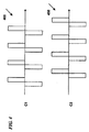
- FIG. 2 illustrates another therapy system 200 in which the implantable pulse generator 101 is connected to percutaneous lead bodies 108 and 109, which are in turn connected to electrodes 110.
- the leads 108, 109 and electrodes 110 are shown in a bipolar configuration with two electrodes 110 carried by each lead 108, 109. In other embodiments, however, the leads 108, 109 can each contain more electrodes 110 (e.g., three, four, five, eight, or more) for applying therapy signals.
- the electrodes e.g., the electrode array 103 or the electrodes 110 of the percutaneous leads 108,109
- FIG 3 is a cross-sectional illustration of a spinal region SR that includes the spinal cord SC and an adjacent vertebra VT (based generally on information from Crossman and Neary, "Neuroanatomy,” 1995 (publ. by Churchill Livingstone )), along with selected representative locations for representative leads 108 (shown as leads 108a-108d) in accordance with several embodiments of the disclosure.
- the spinal cord SC is situated between a ventrally located vertebral body WB and a dorsally located vertebral body DVB that includes a transverse process 198 and spinous process 197.
- Arrows V and D identify ventral and dorsal directions, respectively.
- the vertebra VT and leads can be at T10 or T11 (e.g., for axial low back pain or leg pain) and in other embodiments of the disclosure, the leads can be placed at other locations.
- the spinal cord SC itself is located within the dura mater DM, which also surrounds portions of the nerves exiting the spinal cord SC, including the dorsal roots DR, dorsal root ganglia G and ventral roots VR.
- the spinal cord SC is illustrated as having identifiable areas of afferent and efferent fibers including ascending pathway areas AP and descending pathway areas DP.
- a lead 108a (e.g., a first lead) can be positioned centrally in a lateral direction (e.g., aligned with the spinal cord midline ML) to provide signals directly to the dorsal column DC of spinal cord SC.
- the first lead can be located laterally from the midline ML.
- single or paired leads can be positioned just off the spinal cord midline ML (as indicated by leads 108b) to provide signals to the dorsal column DC.
- One or more other leads can be positioned proximate to the dorsal root DR or dorsal root entry zone DREZ (e.g., 1-4 mm from the spinal cord midline ML, as indicated generally by lead 108c), and/or proximate to the dorsal root ganglion G (as indicated by lead 108d).
- Other suitable locations for the second lead include the "gutter,” also located laterally from the midline ML.
- the leads 108 may have other locations proximate to the spinal cord SC and/or proximate to other target neural populations e.g., laterally from the midline ML and medially from the dorsal root ganglion 194.
- the leads can be located subdurally rather epidurally, as shown in dashed lines for midline lead 108a and off-midline leads 108b.
- the practitioner may select any of a variety of combinations of the foregoing locations, depending on the particular patient's needs and condition.
- the practitioner can place two leads, each positioned to direct signals to a different target location (e.g., neural population) of the patient's spinal cord SC.
- a single lead may have electrodes positioned at two or more target locations. In either case, individual electrodes can deliver signals with different characteristics to different neural populations to achieve a beneficial effect for the patient.
- LF low-frequency
- SCS Spinal Cord Stimulation
- the LF signal can have a frequency in the range of up to about 1,500 Hz, and a pulse width equal to or less than half of the period of the signal.
- the LF signal can have a frequency in the range of from about 40 Hz to about 500 Hz.
- a high-frequency (HF) therapy signal can produce a block or partial block on the nerves.
- block refers generally to an at least partial block (e.g., a partial or complete block)
- blocking signal refers generally to a signal that creates an at least partial block.
- a desired effect on the patient e.g., pain reduction
- This block inhibits and/or prevents excitatory responses from reaching the brain of the patient.
- the HF therapy signal includes a biphasic signal.
- the HF therapy signal is a biphasic (alternating current) signal having a 50% duty cycle and a frequency in the range of from about 2,500 Hz to about 100,000 Hz.
- the HF signal can have a frequency in the range of from about 2,500 Hz to about 20,000 Hz, and in further particular embodiments, about 3,000 Hz to about 10,000 Hz.
- HF signal waveforms that can be applied to the dorsal column DC ( Figure 3 ) are shown in Figures 4 and 5 .
- the signal waveforms shown in Figure 4 include biphasic, charge balanced, square wave pulses.
- a first waveform 400 is applied to a first signal channel C1 and a second waveform 450 is applied to a second signal channel C2.
- the waveform on the first signal channel C1 is interlaced with the waveform on the second signal channel C2 to minimize interaction between the signals 400, 450.
- This option is generally available when the HF signal is applied at a duty cycle of less than 50%, using one or more contacts that are shared between the first channel C1 and the second channel C2.
- Figure 5 illustrates biphasic, charge balanced, sinusoidal pulses 500, 550 which can be applied via the first and second signal channels C1, C2, respectively.
- a physician or other practitioner can choose to combine two or more of the treatment processes described below for administering therapy for chronic pain management.
- the combination of the different types of therapy can provide pain relief on multiple fronts, providing extended coverage to the patient.
- multiple treatment processes can be applied to a patient simultaneously.
- the therapies can be combined, but chronologically spaced, or offset, which can also have advantages.
- one therapy signal can be used to facilitate the initialization and/or the maintenance of another therapy signal.
- a representative first treatment process for administering therapy for chronic pain management includes applying an HF blocking signal directly to the dorsal column DC of the patient.
- Figure 6 is a schematic depiction of a representative HF blocking signal 600 applied to the dorsal column DC.
- This HF blocking signal can be applied to the dorsal column DC in place of an LF stimulation signal to replace the pain relief provided by the paresthesia.
- the HF stimulation blocking signal 600 is applied to the dorsal column DC to establish a partial or total neuronal block at the dorsal column DC sufficient to block the chronic pain felt by the patient.
- the HF therapy signal can be applied to one or more select regions (e.g., vertebral levels) of the dorsal column DC to block transmission of pain signals from lower dermatomes.
- the HF blocking signal can inhibit or prevent the sensation of pain (e.g., to effect anesthesia) in the dermatomes corresponding to the selected regions.
- an HF blocking signal is applied to one or more dorsal roots DR and/or dorsal root ganglion(s) G of a patient, instead of directly to the dorsal column DC.
- Figure 7 is a schematic depiction of an example HF blocking signal 700 applied to the dorsal root DR. Blocking at the dorsal root DR and/or the dorsal root ganglion G facilitates blocking sensation signals associated with one or more select regions of the body. In contrast, blocking at the dorsal column DC generally blocks only tactile and proprioceptive signals, generally at all dermatomes associated with sections of the dorsal column DC located below the blocking electrodes.
- Arranging the electrodes e.g., the electrodes carried by the array 103 shown in Figure 1 or the electrodes 110 shown in Figure 2 ) at the dorsal root DR and/or dorsal root ganglion G can enhance the range and effectiveness of the therapy signals.
- the CSF fluid layer is not as thick as it is at the dorsal column DC, which can allow more current to flow to the spinal region.
- the CSF fluid layer is thicker closer to the dorsal column DC, which can shunt much of the current before the current reaches the dorsal column DC.
- sensory nerve responses typically proceed through the dorsal roots DR to the dorsal column DC, whereas motor nerve responses proceed through the ventral roots VR (see Figure 3 ) to the spinal cord SC.
- Applying therapy signals to the dorsal root DR therefore, can facilitate blocking of sensory responses (e.g., pain) without decreasing or eliminating the transmission of motor control impulses.
- an HF blocking signal can be applied to the peripheral nerves of the patient (e.g., the nerves distal of the spinal cord SC).
- an HF blocking signal can be applied to the somatic nerves of the patient.
- the HF blocking signal can be applied to the autonomic nerves of the patient. Applying the HF block to the peripheral nerves can enable placement of the electrodes away from the spinal cord SC and the spinal fluid, and can therefore reduce the likelihood for interference with spinal function.
- HF blocking signal can facilitate the inducement of paresthesia by alleviating patient discomfort resulting from the application of the LF stimulation signal.
- an LF stimulation signal to the dorsal column DC can induce paresthesia and/or induce patient discomfort, depending on the distance between the electrode(s) and the spinal cord (e.g., the thickness of the intermediate cerebral spinal fluid layer).
- the term “discomfort” refers generally to an unpleasant, undesirable, uncomfortable and/or unwanted sensation or other response. The term includes, but is not limited to, pain.
- patient discomfort results from the inadvertent application of the electric field produced by the electrode(s) to an adjacent dorsal root DR.
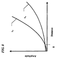
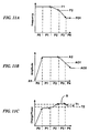
- Figure 8 schematically depicts the amplitude of an LF stimulation signal likely to induce paresthesia (represented by threshold curve T P ) and the amplitude of the LF stimulation signal likely to induce patient discomfort (represented by threshold curve T D ) as a function of spacing between the electrodes and the spinal cord.
- Figure 8 is not intended as an exact plot of amplitude as a function of the spacing, but rather is intended to illustrate the general relationship amongst the paresthesia threshold T P , the patient discomfort threshold T D , and the spacing.
- the LF stimulation signal can stimulate the dorsal root
- the paresthesia threshold T P and the patient discomfort threshold T D cross at the electrode spacing distance X, which is approximately 2 mm in at least some embodiments of the disclosure, and can vary depending on factors that include signal delivery parameters. Further details regarding the relationship amongst electrode spacing, paresthesia, and pain can be found, e.g., in Effectiveness of Spinal Cord Stimulation in the Management of Chronic Pain: Analysis of Technical Drawbacks and Solutions by Jan Holsheimer (Neurosurgery, Vol. 40, No. 5, May 1997 ), the disclosure of which is hereby incorporated herein by reference in its entirety.
- Some combination treatment processes in accordance with embodiments of the disclosure for administering therapy for chronic pain management use an HF blocking signal to inhibit the discomfort sensation produced when the LF signal amplitude reaches the discomfort threshold T D , thereby enabling the amplitude of the LF signal to be increased further to the paresthesia threshold T P .
- This in turn can allow the LF signal to be effective, even if it is provided by an electrode that would otherwise be too far away from the target nerve region (e.g., the dorsal column) to produce paresthesia without also producing discomfort.
- Other combination treatment processes augment the pain relief provided by paresthesia with the pain relief provided by blocking different sections of the spinal region, as will be discussed later.
- a representative fourth treatment process for administering therapy for chronic pain management applies an HF blocking signal to the dorsal root DR (and/or dorsal root ganglion G) while applying the LF stimulating signal at the dorsal column DC.
- the term "dorsal root” can include the dorsal root itself, the dorsal root entry region, and the conus.
- Figure 9 is a schematic illustration of an HF blocking signal 900 applied to the dorsal root DR of a patient, and an LF stimulating signal 950 applied to the dorsal column DC.
- the HF signal can establish a block on the dorsal root DR that inhibits the transmission to the brain of pain sensations induced by the electric field of the LF stimulation signal.
- the HF blocking signal 900 is applied to the dorsal root DR prior to application of the LF stimulating signal 950 to the dorsal column DC. In other embodiments of the disclosure, however, the HF blocking signal 900 can be applied at generally the same time as or after the LF stimulating signal 950 is applied to the dorsal column DC. In one embodiment of the disclosure, the LF stimulation signal 950 can be initiated with a low-level amplitude that is subsequently ramped up to a suitable operating amplitude.
- the HF blocking signal applied to the dorsal root DR augments the pain relief provided by the paresthesia.
- blocking the dorsal root DR is expected to block peripheral pain (e.g., any peripheral pain) from being transmitted through the dorsal root DR. This can include not only discomfort caused by the LF signal, but also the pain that the LF signal is expected to address.
- a representative fifth treatment process for administering therapy for chronic pain management applies an HF blocking signal at a first section of the dorsal column DC while applying the LF stimulating signal at a second section the dorsal column DC.
- the LF stimulating signal is expected to induce a sensation of paresthesia in dermatomes (e.g., all dermatomes) associated with the second section of the dorsal column DC and lower sections (e.g., all lower sections).
- the HF blocking signal is expected to block excitatory responses produced at the first section and lower sections from reaching the brain.
- the HF blocking signal is applied to the dorsal column DC prior to application of the LF stimulating signal to the dorsal column DC. In other embodiments of the disclosure, however, the HF blocking signal can be applied at substantially the same time as or after the LF stimulating signal is applied. In one embodiment of the disclosure, the LF stimulation signal can be initiated with a low-level amplitude that is subsequently ramped up to a suitable operating amplitude.
- the HF blocking signal applied to the dorsal column DC augments the pain relief provided by the paresthesia.
- the LF stimulating signal can boost nerve responses that inhibit the sensation of pain and the HF blocking signal can inhibit nerve responses that transmit pain signals to the brain.
- the HF signal can be applied to the dorsal column DC above (superior) or below (inferior) the site at which the LF signal is applied.
- Signals applied to the dorsal column DC will tend to induce action potentials in both directions along the target sensory signal route, e.g., toward the brain (orthodromic) and away from the brain (antidromic). If the orthodromic LF signal creates a pleasant (or at least non-objectionable) sensation, such as tingling, that masks the target pain, then there may be no need for an HF signal applied to the dorsal column DC.
- the patient can be outfitted with a device that includes an LF signal generator coupled to electrical contacts at the dorsal column, and an HF signal generator coupled to electrical contacts located superiorly on the dorsal column DC.
- the HF signal generator is activated if (a) the paresthesia created by the LF signal is objectionable to the patient, and (b) the antidromic action potentials created by the LF signal reduce the target pain.
- the HF signals can be applied to the dorsal column DC at a location inferior to where the LF signals are applied.
- the antidromic signals produced by the LF signals do not contribute (or do not contribute significantly) to reducing the target pain. Accordingly, applying HF signals at an inferior location, which is expected to block such antidromic signals, is not expected to impact the effectiveness of the LF signals, e.g., the orthodromic paresthesia effect.
- dorsal column DC fibers transmit pain, in contrast to more traditional models which posit that pain travels through the spinothalamic tract. Based on this assumption, blocking orthodromic pain signals passing along the dorsal column is expected to reduce the target pain.
- the therapy systems 100, 200 can be utilized to provide chronic pain management to patients using one of the above described therapy options, or one or more combinations thereof.
- the following treatment parameters are representative of treatment parameters in accordance with particular embodiments.
- HF blocking signals can have a frequency ranging between about 2,500 Hz and about 100,000 Hz.
- the HF blocking signal has a frequency ranging between about 2,500 Hz and about 20,000 Hz and in another particular embodiment of the invention, between about 3,000 Hz and about 10,000 Hz.
- the HF signal has a frequency of greater than 10,000 Hz. Frequencies above 10,000 Hz may result in shorter transition times, e.g., shorter times required to establish a block.
- the current of the HF blocking signals generally can range from about 2 mA to about 20 mA. In a particular embodiment of the invention, the current of a representative HF blocking signal is about 5-10 mA.
- the amplitude of the blocking signal can be reduced from a first operating level to a second, lower operating level without affecting the sensory experience of the patient.
- the amplitude of the HF blocking signal can be reduced by about 10-30% after initialization without affecting the established block.
- Such a result can advantageously decrease the amount of power required to operate the therapy system 100, 200 ( Figures 1 and 2 ). For example, decreasing the operating power can increase the battery life of the pulse generator 101 or otherwise decrease the drain on the power source.
- therapy can be applied in a discontinuous fashion so as to include periods when the therapy is applied, and periods when the therapy is terminated according to a duty cycle.
- therapy application periods can range from a few seconds to a few hours.
- the duty cycle of a therapy signal can extend over a few milliseconds.
- HF blocking signals When HF blocking signals are initially applied to nerve fibers, the patient can experience an onset response before the block takes effect.
- An onset response is induced by a brief activation of the nerve fibers resulting in sudden pain and/or involuntary muscle contractions. Such an onset response can occur regardless of whether the therapy signals are applied to the dorsal column DC, the dorsal root DR, the dorsal root ganglions G, or to the peripheral nerves of the patient.
- the nerve activation caused by initializing the blocking signal can be mitigated by adjusting the signal parameters (e.g., amplitude and/or frequency) of the blocking signal.
- the signal parameters e.g., amplitude and/or frequency
- patient discomfort caused by the onset response can be masked by applying additional pain management therapy.
- mitigation of an onset response refers generally to a decrease in the otherwise resulting activation of the nerve to which the blocking signal is being applied.
- a first initialization procedure for mitigating patient onset response includes gradually ramping up the amplitude of the blocking signal being applied to the nerve.
- the amplitude of the blocking signal can refer to the current amplitude and/or the voltage amplitude of the signal since a direct relationship exists between the current and the voltage of the blocking signal.
- the amplitude and/or frequency of representative blocking signal 1000 is gradually increased to an operating amplitude OA over a finite period of time.
- the amplitude of the waveform 1000 is increased over a period of a few seconds.
- the amplitude and/or frequency can be increased over a greater or lesser period of a time (e.g., a few minutes or a few milliseconds).
- the amplitude and/or frequency can be decreased over time, as is discussed further below with reference to Figures 11A-11C .
- a second initialization procedure for reducing the onset response to treatment can include at least two phases, one in which the applied frequency and/or amplitude are above general operating levels, and one in which the frequency and/or amplitude are reduced to operating levels. These phases, as well as additional (and in some cases, optional) phases are described below.
- the second initialization procedure can include an optional onset phase P0 during which the frequency of the blocking signal is maintained at a constant level F1 (see Figure 11 A) and the amplitude of the blocking signal is ramped up from a low amplitude A1 to a high amplitude A2 (see Figure 11 B) .
- a blocking signal having a frequency F1 and amplitude A2 greater than the general operating frequency FO1 and operating amplitude AO1 is applied to a nerve.
- a blocking signal having a frequency in the range of about 2,500 Hz to above 20 KHz and an amplitude up to about 20 mA can be applied during the first phase P1.
- the application of the blocking signal having a very high frequency F1 and a high amplitude A2 rapidly results in a block on the nerve.
- the second initialization procedure can include an optional transition phase P2 during which a block is established (i.e., during which the signal increases in strength above the threshold T1). Even when the transition phase P2 is utilized, however, the blocking signal establishes a block on the nerve more rapidly than would a signal that simply has the operating frequency and operating amplitude.
- the frequency of the blocking signal is decreased from the very high frequency F1 to a frequency F2 (see Figure 11A ).
- Frequency F2 is lower than frequency F1, but still significantly higher than the operating frequency FO. Decreasing the frequency increases the charge per phase and hence the strength of the blocking signal (see Figure 11 C) .
- the frequency is lowered until the signal strength crosses the blocking threshold T1.
- the amplitude may be further increased as well during the transition phase P2.
- the frequency and amplitude of the blocking signal can be reduced from a level at which the block is established to first operating levels (e.g., FO1, AO1 shown in Figure 11B ).
- a block is established when the charge per phase of the blocking signal passes above a blocking threshold T1 (see Figure 11C ). Decreasing the amplitude of the blocking signal lessens the drain on the power source. Decreasing the frequency increases the charge per phase (e.g., the stimulation applied to the nerve fibers) to compensate for the reduction in amplitude.
- a practitioner begins ramping down the frequency and the amplitude concurrently. In other embodiments of the disclosure, however, the amplitude and frequency can be ramped down at different times.
- an optional phase P4 includes decreasing the amplitude of the signal from the first operating level AO1 to a different operating level AO2 after the block is established (see Figure 11B ). Decreasing the amplitude lowers the charge per phase (see Figure 11 C) .
- the block can be maintained, even if the charge per phase drops below the first threshold T1, as long as the charge per phase does not drop below a second threshold T2 (see Figure 11 C) .
- threshold T2 is 10-30% less than the threshold T1.
- Figure 12 is a schematic depiction of an example blocking signal 1200 initially having a high frequency F1 (e.g., about 30-50 KHz) and a high amplitude A2 (e.g., about 15-20 mA).
- the blocking signal 1200 is a biphasic, charge balanced, square waveform. In other embodiments of the disclosure, however, the blocking signal 1200 can include any desired waveform.
- the amplitude of the blocking signal 1200 is ramped down to an appropriate operating level AO (e.g., about 5-10 mA).
- the frequency of the blocking signal 1200 also can be decreased to an appropriate operating level FO (e.g. about 3-10 KHz).
- Figure 13 shows the blocking signal 1200 having an initial ramp-up period shown at 1200a, during which the signal amplitude is increased to a maximum amplitude MA. Ramping up the amplitude of the signal can allow the signal to be initiated safely with reduced or non-existent patient discomfort. In other embodiments of the disclosure, however, the onset phase P0 can be skipped and the very high amplitude A2 of the blocking signal can be applied from the beginning.
- masking of an onset response refers generally to a decrease in the discomfort of the patient otherwise resulting from an onset response, without affecting activation of the nerve to which the blocking signal is being applied.
- paresthesia induced by an LF stimulating signal applied to the dorsal column DC can mitigate the onset response of an HF blocking signal applied to the dorsal root DR.
- the low-level paresthesia while not strong enough to control the chronic pain of the patient, can alleviate some or all of the discomfort experienced by the patient as a result of the initialization of the HF blocking signal. Examples of the relative timing for the therapy signals are shown in Figure 14 .
- an LF stimulating signal 1450 having a low amplitude and a low frequency (e.g., in the range of about 40 Hz to about 250 Hz) is applied to the dorsal column DC of a patient to induce paresthesia.
- an HF blocking signal 1400 having a high frequency e.g., ranging from about 2,500 Hz to about 100,000 Hz, and in a particular embodiment of the disclosure, from about 2,500 Hz to about 20,000 Hz, and in a further particular embodiment, about 2,500 Hz to about 10,000 Hz
- a high frequency e.g., ranging from about 2,500 Hz to about 100,000 Hz, and in a particular embodiment of the disclosure, from about 2,500 Hz to about 20,000 Hz, and in a further particular embodiment, about 2,500 Hz to about 10,000 Hz
- the paresthesia induced by stimulating the dorsal column DC can enhance patient comfort while the partial or complete HF block is established at the dorsal root DR.
- an LF signal is applied to the dorsal column DC for a period of several seconds before applying the HF signal, at least up to an amplitude below that which causes discomfort and/or pain.
- the LF signal can be halted once the HF signal is established and the period for experiencing an onset response has passed. In a representative embodiment of the disclosure, this time period can be from about 5 seconds to about 5 minutes.
- the LF signal can then be re-established for a short period the next time an HF signal is initiated to again reduce or eliminate the onset response. In this manner, the onset response can be controlled without requiring a continuous (and therefore power consuming) LF signal.
- This arrangement can be used when the LF signal is applied at a location superior to the HF signal location, e.g., when both the LF and HF signals are applied to the dorsal column DC, or when the LF signal is applied to the dorsal column DC above a dorsal root DR location at which the HF signal is applied.
- One or more pharmaceutical drugs affecting the pain neural transmission synapse or neuromuscular junction also can be given to the patient prior to initiating a therapy signal, such as an HF blocking signal.
- a therapy signal such as an HF blocking signal.
- bupivacaine and/or other suitable local anesthetics may be used in this regard, when injected epidurally.
- the various classes of analgesics used for epidural and spinal block include local anesthetics, opioids, adrenergic agonists, and cholinergic agonists.
- Local anesthetics inhibit neural conduction by reversibly blocking conductance in axonal sodium channels.
- Opioids exert their effect by reversibly binding to opioid receptors in the dorsal horn of the spinal cord.
- Alpha-2 adrenergic agents interact with alpha-2 adrenergic receptors in the spinal cord, and cholinergic agonists produce analgesia by increasing the concentration of acetylcholine proximate to muscarinic and nicotinic receptors in the superficial layers of the dorsal horn of the spinal cord.
- the pharmacological agent can be delivered via the same device that supplies the electrical signals, or the agent can be delivered via a separate device.
- PLGA or another suitable polymer can be used to exude the agent.
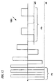
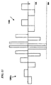
- Figures 15-18 illustrate different design variations that include an electrode array having four electrodes.
- arrays can include a greater or lesser number of electrodes arranged in the same or other patterns.
- an array can contain two electrodes.
- an array can contain three electrodes.
- an array can contain up to sixteen or more electrodes. Increasing the number of electrodes increases the number of channel vectors which can be utilized during therapy, thereby broadening the types of therapy applied and/or the regions over which the therapy is applied.
- Figure 15 illustrates an example electrode array 119 including four electrodes 115, 116, 117, 118 implanted at the spinal cord SC.
- a first therapy signal (e.g., for affecting paresthesia at the dorsal column DC) is applied via a first output channel C1 (shown schematically) of the array 119 that extends along the dorsal column DC and can include a first pair of electrodes 116, 117.
- a second therapy signal (e.g., for blocking pain in the dorsal root DR) is transmitted via a second output channel C2 (shown schematically) of the array 119 that extends at an angle (e.g., 10°, 30°, 60°, 90°, 120°, etc.) to the first output channel C1 and can include a second pair of electrodes 115, 116.
- an angle e.g. 10°, 30°, 60°, 90°, 120°, etc.
- the vector of the electrical stimulation applied via the first channel C1 between electrode 116 and electrode 117 is angled relative to the vector of the electrical stimulation applied through the second channel C2 between electrode 116 and electrode 115.
- the electrodes By arranging the electrodes to provide angled (e.g., orthogonal) signal channels C1, C2, electric field interaction between the channels C1, C2 can be reduced or minimized.
- the first channel C1 can be oriented to align with the dorsal column DC and the second channel C2 can be oriented to align with the dorsal root DR.
- the second channel C2 can be arranged generally orthogonal adjacent the thoracic region of the spine, and more acutely angled closer to the lumbar region.
- the remaining electrode 118 can be used to create other channels for applying therapy signals. For example, if the dorsal root crosses the electrode array 119 above the second pair of electrodes 115, 116, then the second therapy signal can be applied along a third channel (not shown) between electrodes 117, 118 to block the dorsal root DR. In other embodiments of the disclosure, the remaining electrode 118 can provide other stimulation vectors for the dorsal column DC to further optimize the therapy.
- one of the first electrodes forms part of both the first channel C1 and the second channel C2
- this arrangement can be suitable when the signals applied to both channels C1, C2 are interlaced.
- this arrangement can be suitable when an HF signal applied to the second channel C2 has a duty cycle of less than 50%, and an LF signal applied to the first channel C1 is interlaced with the HF signal.
- an additional first electrode 116a is used in combination with the electrode 117 for the first channel C1, and electrodes 115, 116 form a separate second channel C2.
- This arrangement can be used when the duty cycle applied to one or both channels C1, C2 is 50%.
- a similar arrangement can be applied to the embodiments shown in other Figures as well, e.g., Figures 16 and 18 .
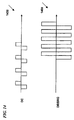
- FIG 16 shows an electrode array 120, which is a variant of the electrode array 119 shown in Figure 15 .
- the electrode array 120 includes an electrode 123 that is laterally offset from the corresponding electrode 115 shown in Figure 14 and accordingly forms a second output channel C2a having an increased length.
- the increased length of the channel C2a produces an electric field having a wider coverage.
- an increased field can be advantageous, for example, when it is desirable to block an increased number of fibers.
- the larger the electric field the greater number of nerve fibers affected by the therapy signal.
- a large electric field penetrates deeper and more laterally into the dorsal column DC, thereby inhibiting pain over a large region of the body (e.g., by covering multiple dermatomes).
- a larger electric field applied to the dorsal column DC may be more likely to "leak" to adjacent fibers on the dorsal root DR or ventral root.
- a larger electric field can stimulate or block fibers carrying motor control impulses (e.g., ventral roots). Large electric fields can be more likely to affect these motor nerve fibers and cause undesirable side effects to the treatment. Accordingly, in at least some such instances, the array 119 shown in Figure 15 may be more appropriate.
- Electrodes within an electrode array also can be axially spaced to increase the penetration along the dorsal column DC.
- an electrode array 121 can include an electrode 124 axially aligned with electrodes 116, 117, but arranged in an axially inferior position relative to the electrode 116.
- channels can be formed between non-adjacent electrodes to increase the length of the channels.
- the electrode 124 can form a first channel C1a with the electrode 117.
- channel length is increased by increasing the spacing between adjacent electrodes.
- electrode arrays can be configured to provide vectors for electrical stimulation that reflect the anatomy of the patient.
- an electrode array 122 shown in Figure 18 includes electrodes 115, 116, 117 that are generally similar to the corresponding electrodes discussed above with reference to the array 119.
- the electrode array 122 includes an electrode 125 spaced axially from electrode 115.
- the electrode 125 is spaced at an axially inferior position relative to electrode 115. Electrode 125 can be included in place of electrode 118 of array 119.
- Electrode array 122 can advantageously provide channel vectors (e.g., channel C2b) oriented in directions generally followed by dorsal roots DR leaving the dorsal column DC at the intervertebral foramen of the spinal cord SC.
- channel vectors e.g., channel C2b
- the dorsal root DR branches from the dorsal column DC at a generally orthogonal orientation relative to the dorsal column DC.
- the dorsal roots DR branch from the dorsal column DC at increasingly downward angles. Accordingly, an array of the type shown in Figure 18 may be particularly suitable for applications distal of the brain.
- a lead configuration 140 shown schematically in Figure 19A , includes a first percutaneous lead 126 that is implanted within the patient together with a second percutaneous lead 130.
- the first percutaneous lead 126 has first and second electrodes 127, 129, respectively, and the second percutaneous lead 130 has first and second electrodes 131, 133, respectively.
- the electrodes 127, 129, 131, 133 are generally aligned along the spinal cord SC.
- the electrodes 127, 129 of the first lead 126 are aligned parallel, but laterally displaced from the electrodes 131, 133 of the second lead 130.
- Therapy signals can be generated using one or both leads 126, 130.
- the therapy signal is typically generated by electrodes arranged along a single lead (e.g., the first lead 126).
- the therapy signal is typically generated by electrodes on two or more different leads (e.g., a first electrode 129 on the first lead 126, and a second electrode 133 on the second lead 130).
- an LF stimulation signal can be applied to the dorsal column DC via the first lead 126 and an HF blocking signal can be applied to the dorsal root DR via electrodes 129, 133 on the first and second leads 126, 130, respectively.
- HF blocking signal can be applied to the dorsal column DC via the electrodes 131, 133 of the second lead 130.
- Figure 19B illustrates another embodiment of the disclosure in which a second lead 130a is positioned along the dorsal root DR and a first lead 126a is positioned along the dorsal column DC (see Figure 19B ).
- an up-regulating (e.g., paresthesia-inducing) signal can be applied to the first lead 126a at the dorsal column DC and a down-regulating (e.g., blocking) signal can be applied to the second lead 130a at the dorsal root DR.
- an up-regulating (e.g., paresthesia-inducing) signal can be applied to the first lead 126a at the dorsal column DC and a down-regulating (e.g., blocking) signal can be applied to the second lead 130a at the dorsal root DR.
- Figure 19C illustrates the inferior portion of the spine, including the lower lumbar and sacral vertebrae, and associated nerve roots.
- Signals e.g., HF signals
- leads or pairs of leads can be positioned between adjacent roots to provide signals to a number of roots that is greater than the number of leads.
- a first pair of leads 152a, 154b, each having electrodes or electrode contacts 160 can be positioned along opposite sides of the S3 root to provide signals to at least the S2, S3 and S4 roots.
- a second pair of leads 152b, 154b can be placed alongside the L5 root to provide signals to the L5 root, the S1 root and optionally the L4 root.
- leads having similar (or other) structures can be placed along other roots.
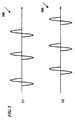
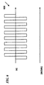
- Figures 20 and 21 illustrate a multi-channel, percutaneous lead arrangement 150 having first and second leads 152, 154 configured to deliver multiple therapy signals to a patient.
- Figure 20 illustrates how the lead arrangement 150 can be used generally to apply therapy signals to the dorsal column DC.
- Figure 21 illustrates how the lead arrangement 150 can be used generally to apply therapy signals to the dorsal root DR.
- the leads 152, 154 can cooperate to provide multiple types of therapy signals to the dorsal column DC and/or dorsal root DR of a patient.
- Each lead 152, 154 of the lead arrangement 150 includes a first arrangement 155 of electrodes, a second arrangement 157 of electrodes, and a third arrangement 159 of electrodes.
- the first and third arrangements 155, 159 include bipolar electrodes.
- the second arrangement 157 includes a tripolar electrode arrangement (e.g., a central cathode with anodes on either side). In such an embodiment, current can be controlled independently to adjust therapy for variations in electrode-to-nerve positioning.
- the leads 152, 154 can include other arrangements of electrodes.
- each lead 152, 154 of the lead arrangement 150 includes seven electrodes. In other embodiments of the disclosure, however, a lead can include one, two, three, four, five, or more electrodes.
- the first arrangement 155 of electrodes on one or both leads 152, 154 can apply an LF stimulation signal to the dorsal column DC to induce a sensation of paresthesia.
- the electric field of the stimulating signal can be generated by electrodes on a single lead so that the electric field is oriented along the length of the dorsal column DC.
- the electrodes of the first arrangement 155 of the first lead 152 create an electric field at the dorsal column DC to induce a sensation of paresthesia.
- the electrodes of the second arrangement 157 of one of the leads 152, 154 can generate an electric field of an HF blocking signal at the dorsal column DC to establish a block on the dorsal column DC.
- the electrodes of the second arrangement 157 can form a tripolar configuration to produce an HF blocking signal as shown in Figure 20 .
- the HF blocking signal can be generated using a lesser or greater number of electrodes of the second arrangement 157.
- the HF blocking signal can be applied to a dorsal root DR along at least some of the electrodes of the second arrangement 157 on both leads 152, 154.
- the middle electrodes of the second arrangement 157 on both leads 152, 154 cooperate to form an electric field. This electric field is oriented generally orthogonal to the electric field form from the tripolar electrode arrangement of Figure 20 .
- FIG. 21 also shows a therapy signal channel between a first electrode 157a and a second electrode 157b.
- the therapy channel is angled with respect to the leads 152, 154. Such an angle may facilitate applying the therapy signal along the length of a dorsal root DR as the root branches from the dorsal column DC.
- therapy can be performed in accordance with other permutations and combinations of the aforementioned parameters, time variations, and therapeutic phases.
- Figure 22 illustrates a first treatment signal 2610 being applied to nerves of a dorsal column DC of a patient.
- the first treatment signal 2610 is an LF signal configured to up-regulate the nerves of the dorsal column DC to induce a sensation of paresthesia, and can be provided by a first portion of the pulse generator 101 described above with reference to Figure 1 .
- a second treatment signal 2620 is applied to a dorsal root DR of the patient subsequent to the initialization of the first treatment signal 2610.
- the second treatment signal 2620 is an HF signal configured to down-regulate the nerves of the dorsal root DR to establish a block on the nerves, and can be provided by a second portion of the pulse generator 101 described above with reference to Figure 1 .
- the paresthesia induced by the first treatment signal 2610 at least partially masks the onset response experienced by the patient when the second treatment signal 2620 is initiated.
- a third treatment signal 2630 is applied to the dorsal column DC after the second treatment signal 2620 is initiated.
- the third treatment signal 2630 is applied to the dorsal column DC after the second treatment signal 2620 establishes a block on the dorsal root DR.
- the third treatment signal 2630 is configured to establish a block on the dorsal column DC.
- a practitioner can implant multiple electrodes at the patient's spinal region, with at least one of the electrodes positioned to provide spinal cord stimulation, and at least one of the electrodes positioned to apply signals to the dorsal root or the dorsal root ganglion.
- the practitioner can then apply an LF signal to the first electrode to induce paresthesia and address pain suffered by the patient.
- the paresthesia may be sufficient to address the patient's pain symptoms, and accordingly, an HF signal need not be applied to the second electrode.
- an initial LF signal applied to the first electrode may not adequately address the patient's pain. In such instances, the amplitude of the signal supplied to the first electrode may be increased to produce paresthesia.
- the increase may be required because the position of the first electrode is not optimal, and/or because of patient-specific physiological effects.
- increasing the amplitude of the signal applied to the first electrode may, at the same time it causes paresthesia, separately cause patient discomfort. Accordingly, the practitioner can apply HF signals to the second electrode to block the patient discomfort, without the need for repositioning the first electrode. This arrangement can accordingly reduce the invasiveness of the implantation procedure.
- the patient may suffer from lower back pain.
- the lower back pain may be transmitted along afferent nerve fibers that enter the spinal column channel at the L5 vertebrae, which is below the end of the spinal cord.
- the practitioner may apply LF spinal cord stimulation at a higher spinal elevation, for example, at the T10 vertebrae.
- the paresthesia resulting from such LF signals may reduce pain somewhat, but not completely.
- the practitioner may additionally apply HF signals at the L5 location to block lower back pain sensations. In this instance, the HF signal is applied at a different spinal elevation than the low frequency signal.
- the patient may suffer from pain transmitted along several neural pathways that enter the spinal column at L1 (e.g., at the conus).
- the practitioner may apply HF signals at the conus, in combination with LF signals at a higher spinal elevation (e.g., T8, T9 or T10). This is unlike several existing stimulation techniques, which deliberately avoid the conus as an implantation/stimulation site.
- the LF signals may be provided on a generally continuous basis in some embodiments of the disclosure, and may be turned off and on automatically in other embodiments of the disclosure, or in response to a patient request in still further embodiments of the disclosure.
- directions and/or instructions were described in the context of a pulse generator, and in other embodiments of the disclosure, such directions and/or instructions may be handled by other controller components.
- Certain aspects of the disclosure described in the context of particular embodiments of the disclosure may be combined or eliminated in other embodiments of the disclosure.
- HF and LF signals were discussed in the context of lower back pain and applied to different spinal elevations, in other embodiments of the disclosure, such signals may be applied at different spinal elevations to address other patient pain symptoms.
- advantages associated with certain embodiments of the disclosure have been described in the context of those embodiments, other embodiments of the disclosure may also exhibit such advantages.
Landscapes
- Health & Medical Sciences (AREA)
- General Health & Medical Sciences (AREA)
- Animal Behavior & Ethology (AREA)
- Veterinary Medicine (AREA)
- Public Health (AREA)
- Neurology (AREA)
- Engineering & Computer Science (AREA)
- Biomedical Technology (AREA)
- Nuclear Medicine, Radiotherapy & Molecular Imaging (AREA)
- Neurosurgery (AREA)
- Radiology & Medical Imaging (AREA)
- Life Sciences & Earth Sciences (AREA)
- Pain & Pain Management (AREA)
- Heart & Thoracic Surgery (AREA)
- Cardiology (AREA)
- Orthopedic Medicine & Surgery (AREA)
- Electrotherapy Devices (AREA)
- Surface Acoustic Wave Elements And Circuit Networks Thereof (AREA)
- Feedback Control In General (AREA)
Priority Applications (3)
| Application Number | Priority Date | Filing Date | Title |
|---|---|---|---|
| EP18172023.6A EP3412335B1 (en) | 2007-11-05 | 2008-11-05 | Multi-frequency neural treatments and associated systems |
| EP16182009.7A EP3156099B1 (en) | 2007-11-05 | 2008-11-05 | Multi-frequency neural treatments and associated systems |
| EP20164038.0A EP3730184B1 (en) | 2007-11-05 | 2008-11-05 | Multi-frequency neural treatments and associated systems |
Applications Claiming Priority (3)
| Application Number | Priority Date | Filing Date | Title |
|---|---|---|---|
| US98535307P | 2007-11-05 | 2007-11-05 | |
| US12/264,836 US20090204173A1 (en) | 2007-11-05 | 2008-11-04 | Multi-Frequency Neural Treatments and Associated Systems and Methods |
| EP08847097.6A EP2207587B1 (en) | 2007-11-05 | 2008-11-05 | Multi-frequency neural treatments and associated systems and methods |
Related Parent Applications (2)
| Application Number | Title | Priority Date | Filing Date |
|---|---|---|---|
| EP08847097.6A Division EP2207587B1 (en) | 2007-11-05 | 2008-11-05 | Multi-frequency neural treatments and associated systems and methods |
| EP08847097.6A Division-Into EP2207587B1 (en) | 2007-11-05 | 2008-11-05 | Multi-frequency neural treatments and associated systems and methods |
Related Child Applications (3)
| Application Number | Title | Priority Date | Filing Date |
|---|---|---|---|
| EP18172023.6A Division EP3412335B1 (en) | 2007-11-05 | 2008-11-05 | Multi-frequency neural treatments and associated systems |
| EP16182009.7A Division EP3156099B1 (en) | 2007-11-05 | 2008-11-05 | Multi-frequency neural treatments and associated systems |
| EP20164038.0A Division EP3730184B1 (en) | 2007-11-05 | 2008-11-05 | Multi-frequency neural treatments and associated systems |
Publications (2)
| Publication Number | Publication Date |
|---|---|
| EP2853285A1 EP2853285A1 (en) | 2015-04-01 |
| EP2853285B1 true EP2853285B1 (en) | 2016-08-17 |
Family
ID=40626146
Family Applications (6)
| Application Number | Title | Priority Date | Filing Date |
|---|---|---|---|
| EP14178370.4A Revoked EP2853285B1 (en) | 2007-11-05 | 2008-11-05 | Multi-frequency neural treatments and associated systems |
| EP18172023.6A Active EP3412335B1 (en) | 2007-11-05 | 2008-11-05 | Multi-frequency neural treatments and associated systems |
| EP08847097.6A Revoked EP2207587B1 (en) | 2007-11-05 | 2008-11-05 | Multi-frequency neural treatments and associated systems and methods |
| EP20164038.0A Active EP3730184B1 (en) | 2007-11-05 | 2008-11-05 | Multi-frequency neural treatments and associated systems |
| EP12190892.5A Revoked EP2630984B1 (en) | 2007-11-05 | 2008-11-05 | Multi-frequency neural treatments and associated systems |
| EP16182009.7A Revoked EP3156099B1 (en) | 2007-11-05 | 2008-11-05 | Multi-frequency neural treatments and associated systems |
Family Applications After (5)
| Application Number | Title | Priority Date | Filing Date |
|---|---|---|---|
| EP18172023.6A Active EP3412335B1 (en) | 2007-11-05 | 2008-11-05 | Multi-frequency neural treatments and associated systems |
| EP08847097.6A Revoked EP2207587B1 (en) | 2007-11-05 | 2008-11-05 | Multi-frequency neural treatments and associated systems and methods |
| EP20164038.0A Active EP3730184B1 (en) | 2007-11-05 | 2008-11-05 | Multi-frequency neural treatments and associated systems |
| EP12190892.5A Revoked EP2630984B1 (en) | 2007-11-05 | 2008-11-05 | Multi-frequency neural treatments and associated systems |
| EP16182009.7A Revoked EP3156099B1 (en) | 2007-11-05 | 2008-11-05 | Multi-frequency neural treatments and associated systems |
Country Status (8)
| Country | Link |
|---|---|
| US (7) | US20090204173A1 (enExample) |
| EP (6) | EP2853285B1 (enExample) |
| JP (4) | JP5677090B2 (enExample) |
| AU (1) | AU2008324795B2 (enExample) |
| CA (1) | CA2704564C (enExample) |
| DE (3) | DE202008018561U1 (enExample) |
| ES (5) | ES2942854T3 (enExample) |
| WO (1) | WO2009061813A1 (enExample) |
Families Citing this family (235)
| Publication number | Priority date | Publication date | Assignee | Title |
|---|---|---|---|---|
| US20120277839A1 (en) | 2004-09-08 | 2012-11-01 | Kramer Jeffery M | Selective stimulation to modulate the sympathetic nervous system |
| US9205261B2 (en) | 2004-09-08 | 2015-12-08 | The Board Of Trustees Of The Leland Stanford Junior University | Neurostimulation methods and systems |
| US8788044B2 (en) | 2005-01-21 | 2014-07-22 | Michael Sasha John | Systems and methods for tissue stimulation in medical treatment |
| US20070073354A1 (en) | 2005-09-26 | 2007-03-29 | Knudson Mark B | Neural blocking therapy |
| WO2008070809A2 (en) * | 2006-12-06 | 2008-06-12 | Spinal Modulation, Inc. | Implantable flexible circuit leads and methods of use |
| CA2671286C (en) | 2006-12-06 | 2017-09-19 | Spinal Modulation, Inc. | Delivery devices, systems and methods for stimulating nerve tissue on multiple spinal levels |
| WO2008070808A2 (en) | 2006-12-06 | 2008-06-12 | Spinal Modulation, Inc. | Expandable stimulation leads and methods of use |
| EP2111253B1 (en) | 2007-01-29 | 2018-05-02 | Spinal Modulation, Inc. | Sutureless lead retention features |
| US10925637B2 (en) * | 2010-03-11 | 2021-02-23 | Mainstay Medical Limited | Methods of implanting electrode leads for use with implantable neuromuscular electrical stimulator |
| US11679261B2 (en) | 2007-03-09 | 2023-06-20 | Mainstay Medical Limited | Systems and methods for enhancing function of spine stabilization muscles associated with a spine surgery intervention |
| US11679262B2 (en) | 2007-03-09 | 2023-06-20 | Mainstay Medical Limited | Systems and methods for restoring muscle function to the lumbar spine |
| US9072897B2 (en) | 2007-03-09 | 2015-07-07 | Mainstay Medical Limited | Systems and methods for restoring muscle function to the lumbar spine |
| US9248278B2 (en) | 2010-03-11 | 2016-02-02 | Mainstay Medical Limited | Modular stimulator for treatment of back pain, implantable RF ablation system and methods of use |
| EP2550991B1 (en) | 2007-03-09 | 2020-09-02 | Mainstay Medical Limited | Neuromuscular electrical stimulation system |
| US11331488B2 (en) | 2007-03-09 | 2022-05-17 | Mainstay Medical Limited | Systems and methods for enhancing function of spine stabilization muscles associated with a spine surgery intervention |
| US20090204173A1 (en) | 2007-11-05 | 2009-08-13 | Zi-Ping Fang | Multi-Frequency Neural Treatments and Associated Systems and Methods |
| US7890182B2 (en) | 2008-05-15 | 2011-02-15 | Boston Scientific Neuromodulation Corporation | Current steering for an implantable stimulator device involving fractionalized stimulation pulses |
| EP2318090B1 (en) * | 2008-05-19 | 2016-01-13 | Nevro Corporation | Implantable neural stimulation electrode assemblies |
| US9056197B2 (en) | 2008-10-27 | 2015-06-16 | Spinal Modulation, Inc. | Selective stimulation systems and signal parameters for medical conditions |
| US8255057B2 (en) | 2009-01-29 | 2012-08-28 | Nevro Corporation | Systems and methods for producing asynchronous neural responses to treat pain and/or other patient conditions |
| US8311639B2 (en) | 2009-07-08 | 2012-11-13 | Nevro Corporation | Systems and methods for adjusting electrical therapy based on impedance changes |
| US8504160B2 (en) * | 2008-11-14 | 2013-08-06 | Boston Scientific Neuromodulation Corporation | System and method for modulating action potential propagation during spinal cord stimulation |
| US8355797B2 (en) | 2009-02-10 | 2013-01-15 | Nevro Corporation | Systems and methods for delivering neural therapy correlated with patient status |
| US8843210B2 (en) * | 2009-03-20 | 2014-09-23 | ElectroCore, LLC | Non-invasive vagal nerve stimulation to treat disorders |
| JP2012521801A (ja) | 2009-03-24 | 2012-09-20 | スパイナル・モデュレーション・インコーポレイテッド | 錯感覚に対する閾値以下の刺激を伴う疼痛の管理 |
| CA2758944C (en) | 2009-04-22 | 2023-03-14 | Konstantinos Alataris | Spinal cord modulation for inducing paresthetic and anesthetic effects, and associated systems and methods |
| AU2015201052B2 (en) * | 2009-04-22 | 2017-04-13 | Nevro Corporation | Selective high frequency spinal cord modulation for inhibiting pain with reduced side effects, and associated systems and methods |
| EP3228350B1 (en) | 2009-04-22 | 2025-09-24 | Nevro Corporation | Device for selective high frequency spinal cord modulation for inhibiting pain with reduced side effects, and associated systems and methods |
| AU2016269457B2 (en) * | 2009-04-22 | 2018-09-06 | Nevro Corporation | Spinal cord modulation for inducing paresthetic and anesthetic effects, and associated systems and methods |
| CA2761778A1 (en) * | 2009-05-15 | 2010-11-18 | Spinal Modulation, Inc. | Methods, systems and devices for neuromodulating spinal anatomy |
| US9463323B2 (en) * | 2009-06-18 | 2016-10-11 | Boston Scientific Neuromodulation Corporation | Spatially selective nerve stimulation in high-frequency nerve conduction block and recruitment |
| US8498710B2 (en) | 2009-07-28 | 2013-07-30 | Nevro Corporation | Linked area parameter adjustment for spinal cord stimulation and associated systems and methods |
| US8843188B2 (en) | 2009-11-23 | 2014-09-23 | Case Western Reserve University | Adjustable nerve electrode |
| US11786725B2 (en) | 2012-06-13 | 2023-10-17 | Mainstay Medical Limited | Systems and methods for restoring muscle function to the lumbar spine and kits for implanting the same |
| US9950159B2 (en) | 2013-10-23 | 2018-04-24 | Mainstay Medical Limited | Systems and methods for restoring muscle function to the lumbar spine and kits for implanting the same |
| US11684774B2 (en) | 2010-03-11 | 2023-06-27 | Mainstay Medical Limited | Electrical stimulator for treatment of back pain and methods of use |
| US12097365B2 (en) | 2010-03-11 | 2024-09-24 | Mainstay Medical Limited | Electrical stimulator for the treatment of back pain and methods of use |
| US9999763B2 (en) | 2012-06-13 | 2018-06-19 | Mainstay Medical Limited | Apparatus and methods for anchoring electrode leads adjacent to nervous tissue |
| US8979915B2 (en) * | 2010-04-19 | 2015-03-17 | Pulsar Scientific, LLC | Separable system for applying compression and thermal treatment |
| JP6231384B2 (ja) | 2010-05-10 | 2017-11-15 | スパイナル・モデュレーション・インコーポレイテッドSpinal Modulation Inc. | 位置ずれを抑制するための方法、システムおよびデバイス |
| US8805519B2 (en) | 2010-09-30 | 2014-08-12 | Nevro Corporation | Systems and methods for detecting intrathecal penetration |
| US8965482B2 (en) * | 2010-09-30 | 2015-02-24 | Nevro Corporation | Systems and methods for positioning implanted devices in a patient |
| US8788046B2 (en) * | 2010-11-11 | 2014-07-22 | Spr Therapeutics, Llc | Systems and methods for the treatment of pain through neural fiber stimulation |
| AU2011336606B2 (en) | 2010-11-30 | 2016-06-23 | Nevro Corporation | Extended pain relief via high frequency spinal cord modulation, and associated systems and methods |
| WO2012094346A2 (en) | 2011-01-03 | 2012-07-12 | The Regents Of The University Of California | High density epidural stimulation for facilitation of locomotion, posture, voluntary movement, and recovery of autonomic, sexual, vasomotor, and cognitive function after neurological injury |
| EP2665514B1 (en) | 2011-01-21 | 2017-07-26 | California Institute of Technology | A parylene-based microelectrode array implant for spinal cord stimulation |
| CA2825763A1 (en) | 2011-02-02 | 2012-08-09 | Spinal Modulation, Inc. | Devices, systems and methods for the targeted treatment of movement disorders |
| KR20140013043A (ko) | 2011-03-24 | 2014-02-04 | 캘리포니아 인스티튜트 오브 테크놀로지 | 신경자극기 |
| WO2012159002A2 (en) | 2011-05-19 | 2012-11-22 | Neuros Medical, Inc. | High-frequency electrical nerve block |
| US10758723B2 (en) | 2011-05-19 | 2020-09-01 | Neuros Medical, Inc. | Nerve cuff electrode for neuromodulation in large human nerve trunks |
| US11413458B2 (en) | 2011-05-19 | 2022-08-16 | Neuros Medical, Inc. | Nerve cuff electrode for neuromodulation in large human nerve trunks |
| US9295841B2 (en) | 2011-05-19 | 2016-03-29 | Meuros Medical, Inc. | High-frequency electrical nerve block |
| EP2739344B1 (en) | 2011-08-02 | 2019-03-20 | Mainstay Medical Limited | Apparatus for anchoring electrode leads for use with implantable neuromuscular electrical stimulator |
| WO2013036880A1 (en) * | 2011-09-08 | 2013-03-14 | Thacker James R | Selective high frequency spinal cord modulation for inhibiting pain, including cephalic and/or total body pain with reduced side effects, and associated systems and methods |
| EP2763743A4 (en) | 2011-10-04 | 2015-08-05 | Nevro Corp | POSITION MODELING OF IMPLANTED DEVICES IN A PATIENT |
| USD736383S1 (en) | 2012-11-05 | 2015-08-11 | Nevro Corporation | Implantable signal generator |
| ES2971060T3 (es) | 2011-11-04 | 2024-06-03 | Nevro Corp | Conjuntos de carga y comunicación para dispositivos médicos para el uso con generadores de señal implantables |
| US9814884B2 (en) | 2011-11-04 | 2017-11-14 | Nevro Corp. | Systems and methods for detecting faults and/or adjusting electrical therapy based on impedance changes |
| US10092750B2 (en) | 2011-11-11 | 2018-10-09 | Neuroenabling Technologies, Inc. | Transcutaneous neuromodulation system and methods of using same |
| BR112014011409A2 (pt) | 2011-11-11 | 2017-05-02 | Neuroenabling Tech Inc | dispositivo de neuromodulação não invasivo para permitir a recuperação de função motora, sensorial, autonômica, sexual, vasomotora e cohnitiva |
| AU2012334926B2 (en) | 2011-11-11 | 2017-07-13 | The Regents Of The University Of California | Transcutaneous spinal cord stimulation: noninvasive tool for activation of locomotor circuitry |
| WO2013111137A2 (en) | 2012-01-26 | 2013-08-01 | Rainbow Medical Ltd. | Wireless neurqstimulatqrs |
| US8676331B2 (en) | 2012-04-02 | 2014-03-18 | Nevro Corporation | Devices for controlling spinal cord modulation for inhibiting pain, and associated systems and methods, including controllers for automated parameter selection |
| US9919148B2 (en) | 2012-05-25 | 2018-03-20 | Boston Scientific Neuromodulation Corporation | Distally curved electrical stimulation lead and methods of making and using |
| US10327810B2 (en) | 2016-07-05 | 2019-06-25 | Mainstay Medical Limited | Systems and methods for enhanced implantation of electrode leads between tissue layers |
| US10195419B2 (en) | 2012-06-13 | 2019-02-05 | Mainstay Medical Limited | Electrode leads for use with implantable neuromuscular electrical stimulator |
| US9186501B2 (en) | 2012-06-13 | 2015-11-17 | Mainstay Medical Limited | Systems and methods for implanting electrode leads for use with implantable neuromuscular electrical stimulator |
| EP2861296A1 (en) | 2012-06-15 | 2015-04-22 | Case Western Reserve University | Therapy delivery devices and methods for non-damaging neural tissue conduction block |
| US10195434B2 (en) | 2012-06-15 | 2019-02-05 | Case Western Reserve University | Treatment of pain using electrical nerve conduction block |
| US9833614B1 (en) | 2012-06-22 | 2017-12-05 | Nevro Corp. | Autonomic nervous system control via high frequency spinal cord modulation, and associated systems and methods |
| US9339655B2 (en) | 2012-06-30 | 2016-05-17 | Boston Scientific Neuromodulation Corporation | System and method for compounding low-frequency sources for high-frequency neuromodulation |
| US9002459B2 (en) | 2012-09-19 | 2015-04-07 | Boston Scientific Neuromodulation Corporation | Method for selectively modulating neural elements in the dorsal horn |
| US9861812B2 (en) | 2012-12-06 | 2018-01-09 | Blue Wind Medical Ltd. | Delivery of implantable neurostimulators |
| US9308022B2 (en) | 2012-12-10 | 2016-04-12 | Nevro Corporation | Lead insertion devices and associated systems and methods |
| US9731133B1 (en) | 2013-01-22 | 2017-08-15 | Nevro Corp. | Systems and methods for systematically testing a plurality of therapy programs in patient therapy devices |
| US9295840B1 (en) | 2013-01-22 | 2016-03-29 | Nevro Corporation | Systems and methods for automatically programming patient therapy devices |
| US9895538B1 (en) | 2013-01-22 | 2018-02-20 | Nevro Corp. | Systems and methods for deploying patient therapy devices |
| WO2014130865A2 (en) | 2013-02-22 | 2014-08-28 | Boston Scientific Neuromodulation Corporation | Neurostimulation system having increased flexibility for creating complex pulse trains |
| US9174053B2 (en) | 2013-03-08 | 2015-11-03 | Boston Scientific Neuromodulation Corporation | Neuromodulation using modulated pulse train |
| AU2014244318A1 (en) | 2013-03-13 | 2015-10-01 | Duke University | Systems and methods for applying electrical stimulation for optimizing spinal cord stimulation |
| CA2906779C (en) | 2013-03-15 | 2022-08-30 | The Regents Of The University Of California | Multi-site transcutaneous electrical stimulation of the spinal cord for facilitation of locomotion |
| WO2014149895A1 (en) * | 2013-03-15 | 2014-09-25 | Boston Scientific Neuromodulation Corporation | Neuromodulation system for providing multiple modulation patterns in a single channel |
| US20140277267A1 (en) * | 2013-03-15 | 2014-09-18 | Boston Scientific Neuromodulation Corporation | Neuromodulation system and method for transitioning between programming modes |
| WO2014179685A1 (en) | 2013-05-03 | 2014-11-06 | Nevro Corporation | Molded headers for implantable signal generators, and associated systems and methods |
| US9180297B2 (en) | 2013-05-16 | 2015-11-10 | Boston Scientific Neuromodulation Corporation | System and method for spinal cord modulation to treat motor disorder without paresthesia |
| WO2014197596A1 (en) | 2013-06-06 | 2014-12-11 | Doan Que T | System for delivering modulated sub-threshold therapy |
| US9950173B2 (en) | 2013-06-06 | 2018-04-24 | Boston Scientific Neuromodulation Corporation | System and method for delivering sub-threshold and super-threshold therapy to a patient |
| US9895539B1 (en) | 2013-06-10 | 2018-02-20 | Nevro Corp. | Methods and systems for disease treatment using electrical stimulation |
| WO2014210373A1 (en) | 2013-06-28 | 2014-12-31 | Boston Scientific Neuromodulation Corporation | Electrode selection for sub-threshold modulation therapy |
| AU2014293164B2 (en) | 2013-07-26 | 2017-07-06 | Boston Scientific Neuromodulation Corporation | Systems of providing modulation therapy without perception |
| US9867991B2 (en) | 2013-07-31 | 2018-01-16 | Nevro Corp. | Physician programmer with enhanced graphical user interface, and associated systems and methods |
| CN104415454B (zh) * | 2013-08-26 | 2017-11-03 | 精能医学股份有限公司 | 改变神经阈值的高频电磁场刺激器 |
| CA2925754C (en) | 2013-09-27 | 2023-02-21 | The Regents Of The University Of California | Engaging the cervical spinal cord circuitry to re-enable volitional control of hand function in tetraplegic subjects |
| US10639476B2 (en) | 2013-10-09 | 2020-05-05 | GiMer Medical Co., Ltd. | Electronic stimulation device, method of treatment and electronic stimulation system |
| TWM498025U (zh) | 2014-10-01 | 2015-04-01 | Gimer Medical Co Ltd | 應用於背根神經節之高頻電刺激器 |
| US10086201B2 (en) | 2013-10-09 | 2018-10-02 | GiMer Medical Co., Ltd. | Electronic stimulation device, method of treatment and electronic stimulation system |
| US10183165B2 (en) | 2013-10-09 | 2019-01-22 | GiMer Medical Co., Ltd. | Method of reducing renal hypertension and computer-readable medium |
| US10086197B2 (en) * | 2013-10-09 | 2018-10-02 | GiMer Medical Co., Ltd. | Method for reducing overactive bladder syndrome and computer-readable medium thereof |
| US10632310B2 (en) | 2013-10-09 | 2020-04-28 | GiMer Medical Co., Ltd. | Electronic stimulation device, method of treatment and electronic stimulation system |
| US9956408B2 (en) | 2013-10-09 | 2018-05-01 | Gimer Medical Co. Ltd. | Method for reducing spasticity and non-transitory computer-readable medium thereof |
| CA3171063C (en) * | 2013-10-23 | 2025-11-18 | Mainstay Medical Ltd | Systems and methods for restoring muscle function to the lumbar spine |
| CN105682733B (zh) * | 2013-10-30 | 2017-12-05 | 波士顿科学神经调制公司 | 用于避免背根刺激的部分控制 |
| AU2014342259B2 (en) | 2013-10-31 | 2017-06-22 | Boston Scientific Neuromodulation Corporation | System to incorporate lead information from image |
| WO2015066303A1 (en) | 2013-11-01 | 2015-05-07 | Boston Scientific Neuromodulation Corporation | Systems for delivering sub-threshold therapy at a midline |
| US10149978B1 (en) | 2013-11-07 | 2018-12-11 | Nevro Corp. | Spinal cord modulation for inhibiting pain via short pulse width waveforms, and associated systems and methods |
| US10010715B2 (en) | 2013-12-04 | 2018-07-03 | Boston Scientific Neuromodulation Corporation | Systems and methods for delivering therapy to the dorsal horn of a patient |
| US9616230B2 (en) | 2013-12-12 | 2017-04-11 | Boston Scientific Neuromodulation Corporation | Systems and methods for programming a neuromodulation system |
| EP3082947B1 (en) * | 2013-12-22 | 2019-03-13 | Research Foundation Of The City University Of New York | Trans-spinal direct current modulation systems |
| WO2015106286A1 (en) | 2014-01-13 | 2015-07-16 | California Institute Of Technology | Neuromodulation systems and methods of using same |
| WO2015109023A1 (en) * | 2014-01-17 | 2015-07-23 | Cardiac Pacemakers, Inc. | Depletion block to block nerve communication |
| US10639477B2 (en) | 2014-01-17 | 2020-05-05 | Cardiac Pacemakers, Inc. | Systems and methods for delivering pulmonary therapy |
| JP2017502787A (ja) * | 2014-01-17 | 2017-01-26 | カーディアック ペースメイカーズ, インコーポレイテッド | シナプス前終末枯渇ブロックを使用した選択的神経刺激 |
| AU2015214607B2 (en) | 2014-02-05 | 2017-05-18 | Boston Scientific Neuromodulation Corporation | System and method for delivering modulated sub-threshold therapy to a patient |
| AU2015214522B2 (en) | 2014-02-05 | 2017-08-31 | Boston Scientific Neuromodulation Corporation | System and method for delivering modulated sub-threshold therapy to a patient |
| EP3145582B1 (en) * | 2014-05-20 | 2020-10-21 | Nevro Corporation | Implanted pulse generators with reduced power consumption via signal strength/duration characteristics, and associated systems |
| WO2016004152A2 (en) | 2014-07-03 | 2016-01-07 | Duke University | Systems and methods for model-based optimization of spinal cord stimulation electrodes and devices |
| CN109908481B (zh) | 2014-07-03 | 2023-06-20 | 波士顿科学神经调制公司 | 具有灵活模式和波形的神经刺激系统 |
| CN106659885B (zh) | 2014-07-24 | 2019-05-28 | 波士顿科学神经调制公司 | 使用多个电场的增强的背角刺激 |
| US10751533B2 (en) | 2014-08-21 | 2020-08-25 | The Regents Of The University Of California | Regulation of autonomic control of bladder voiding after a complete spinal cord injury |
| WO2016032929A2 (en) * | 2014-08-26 | 2016-03-03 | Avent, Inc. | Selective nerve fiber block method and system |
| US10773074B2 (en) | 2014-08-27 | 2020-09-15 | The Regents Of The University Of California | Multi-electrode array for spinal cord epidural stimulation |
| CN106687173A (zh) | 2014-09-15 | 2017-05-17 | 波士顿科学神经调制公司 | 用于对神经刺激脉冲模式进行编程的图形用户界面 |
| JP6437638B2 (ja) | 2014-09-23 | 2018-12-12 | ボストン サイエンティフィック ニューロモデュレイション コーポレイション | 後角刺激を較正するためのシステム |
| CN107073266B (zh) | 2014-09-23 | 2020-08-11 | 波士顿科学神经调制公司 | 用于接收电极列表的用户提供的选择的系统和方法 |
| AU2015321575B2 (en) | 2014-09-23 | 2018-05-10 | Boston Scientific Neuromodulation Corporation | Perception calibration of neural tissue using field troll |
| JP6580678B2 (ja) | 2014-09-23 | 2019-09-25 | ボストン サイエンティフィック ニューロモデュレイション コーポレイション | バースト刺激を用いた神経変調 |
| AU2015321491B2 (en) | 2014-09-23 | 2018-09-27 | Boston Scientific Neuromodulation Corporation | Short pulse width stimulation |
| JP6498754B2 (ja) | 2014-09-23 | 2019-04-10 | ボストン サイエンティフィック ニューロモデュレイション コーポレイション | 患者入力に応答する知覚以下変調 |
| WO2016048951A1 (en) | 2014-09-23 | 2016-03-31 | Boston Scientific Neuromodulation Corporation | Neuromodulation specific to objective function of modulation field for targeted tissue |
| US10471268B2 (en) | 2014-10-16 | 2019-11-12 | Mainstay Medical Limited | Systems and methods for monitoring muscle rehabilitation |
| EP3191176B1 (en) | 2014-10-22 | 2024-04-10 | Nevro Corp. | Systems and methods for extending the life of an implanted pulse generator battery |
| AU2015343483B2 (en) | 2014-11-04 | 2018-03-01 | Boston Scientific Neuromodulation Corporation | Method and apparatus for programming complex neurostimulation patterns |
| US9597521B2 (en) | 2015-01-21 | 2017-03-21 | Bluewind Medical Ltd. | Transmitting coils for neurostimulation |
| US9764146B2 (en) | 2015-01-21 | 2017-09-19 | Bluewind Medical Ltd. | Extracorporeal implant controllers |
| US10004896B2 (en) | 2015-01-21 | 2018-06-26 | Bluewind Medical Ltd. | Anchors and implant devices |
| US9849287B2 (en) | 2015-02-09 | 2017-12-26 | Boston Scientific Neuromodulation Corporation | System and method for determining the neurological position of epidural leads |
| US9517344B1 (en) | 2015-03-13 | 2016-12-13 | Nevro Corporation | Systems and methods for selecting low-power, effective signal delivery parameters for an implanted pulse generator |
| US11167139B2 (en) | 2015-03-20 | 2021-11-09 | Medtronic Sg, Llc | Method and apparatus for multi modal electrical modulation of pain using composite electromagnetic fields |
| US12311177B2 (en) | 2015-03-20 | 2025-05-27 | Medtronic Sg, Llc | Method and apparatus for multi modal electrical modulation of pain using composite electromagnetic fields |
| US10039930B2 (en) | 2015-03-20 | 2018-08-07 | Stimgenics, Llc | Method and apparatus for multimodal electrical modulation of pain |
| US10850102B2 (en) | 2015-03-20 | 2020-12-01 | Medtronic Sg, Llc | Method and apparatus for multimodal electrical modulation of pain |
| AU2016268007B2 (en) | 2015-05-28 | 2019-04-18 | Boston Scientific Neuromodulation Corporation | Neuromodulation using stochastically-modulated stimulation parameters |
| US9782589B2 (en) | 2015-06-10 | 2017-10-10 | Bluewind Medical Ltd. | Implantable electrostimulator for improving blood flow |
| US10335601B2 (en) | 2015-07-30 | 2019-07-02 | Boston Scientific Neuromodulation Corporation | User interface for custom patterned electrical stimulation |
| GB201513596D0 (en) | 2015-07-31 | 2015-09-16 | Univ Ulster The | Transcutaneous energy transfer systems and methods |
| US9630012B2 (en) | 2015-08-06 | 2017-04-25 | Meagan Medical, Inc. | Spinal cord stimulation with interferential current |
| US11298533B2 (en) | 2015-08-26 | 2022-04-12 | The Regents Of The University Of California | Concerted use of noninvasive neuromodulation device with exoskeleton to enable voluntary movement and greater muscle activation when stepping in a chronically paralyzed subject |
| US10456586B2 (en) | 2015-10-15 | 2019-10-29 | Boston Scientific Neuromodulation Corporation | User interface for neurostimulation waveform composition |
| US11318310B1 (en) | 2015-10-26 | 2022-05-03 | Nevro Corp. | Neuromodulation for altering autonomic functions, and associated systems and methods |
| US11097122B2 (en) | 2015-11-04 | 2021-08-24 | The Regents Of The University Of California | Magnetic stimulation of the spinal cord to restore control of bladder and/or bowel |
| US10105540B2 (en) | 2015-11-09 | 2018-10-23 | Bluewind Medical Ltd. | Optimization of application of current |
| US9713707B2 (en) | 2015-11-12 | 2017-07-25 | Bluewind Medical Ltd. | Inhibition of implant migration |
| US10300277B1 (en) | 2015-12-14 | 2019-05-28 | Nevro Corp. | Variable amplitude signals for neurological therapy, and associated systems and methods |
| US10864373B2 (en) | 2015-12-15 | 2020-12-15 | Case Western Reserve University | Systems for treatment of a neurological disorder using electrical nerve conduction block |
| US10639471B2 (en) | 2015-12-16 | 2020-05-05 | Brainlab Ag | Simulating a target coverage for deep brain stimulation |
| US11083896B2 (en) | 2015-12-18 | 2021-08-10 | Medtronic, Inc. | High duty cycle electrical stimulation therapy |
| WO2017116760A1 (en) | 2015-12-31 | 2017-07-06 | Nevro Corp. | Controller for nerve stimulation circuit and associated systems and methods |
| CN109310865B (zh) | 2016-01-25 | 2022-09-13 | 内弗洛公司 | 电刺激治疗充血性心力衰竭,以及相关联的系统和方法 |
| WO2017142948A1 (en) | 2016-02-19 | 2017-08-24 | Nalu Medical, Inc. | Apparatus with enhanced stimulation waveforms |
| US10799701B2 (en) | 2016-03-30 | 2020-10-13 | Nevro Corp. | Systems and methods for identifying and treating patients with high-frequency electrical signals |
| US20170281949A1 (en) | 2016-03-30 | 2017-10-05 | Nevro Corp. | Distributed electrode lead configurations and associated systems and methods |
| US10549099B2 (en) * | 2016-04-29 | 2020-02-04 | University Of Utah Research Foundation | Electronic peripheral nerve stimulation |
| US10369354B2 (en) | 2016-05-17 | 2019-08-06 | Boston Scientific Neuromodulation Corporation | Systems and method for anchoring a lead for neurostimulation of a target anatomy |
| US11446504B1 (en) | 2016-05-27 | 2022-09-20 | Nevro Corp. | High frequency electromagnetic stimulation for modulating cells, including spontaneously active and quiescent cells, and associated systems and methods |
| WO2017210491A1 (en) | 2016-06-01 | 2017-12-07 | Duke University | Systems and methods for determining optimal temporal patterns of neural stimulation |
| AU2017280112B2 (en) | 2016-06-24 | 2022-11-17 | Saluda Medical Pty Ltd | Neural stimulation for reduced artefact |
| US10780274B2 (en) | 2016-08-22 | 2020-09-22 | Boston Scientific Neuromodulation Corporation | Systems and methods for delivering spinal cord stimulation therapy |
| US10525268B2 (en) | 2016-08-23 | 2020-01-07 | Medtronic, Inc. | Delivery of independent interleaved programs to produce higher-frequency electrical stimulation therapy |
| EP4230253B1 (en) | 2016-10-28 | 2025-02-19 | Medtronic, Inc. | High frequency stimulation based on low frequency titration gauge |
| US11123565B1 (en) | 2016-10-31 | 2021-09-21 | Nevro Corp. | Treatment of neurodegenerative disease with high frequency stimulation, and associated systems and methods |
| US10716935B2 (en) | 2016-11-04 | 2020-07-21 | Boston Scientific Neuromodulation Corporation | Electrical stimulation leads, systems and methods for stimulation of dorsal root ganglia |
| WO2018089906A1 (en) | 2016-11-14 | 2018-05-17 | Verily Life Sciences Llc | Systems and methods for active charge-balancing for high-frequency neural stimulation |
| US10124178B2 (en) | 2016-11-23 | 2018-11-13 | Bluewind Medical Ltd. | Implant and delivery tool therefor |
| JP2018082870A (ja) * | 2016-11-24 | 2018-05-31 | 株式会社ジーウェーブ | 電気治療器 |
| EP4349398A3 (en) | 2016-12-23 | 2024-06-19 | Ecole Polytechnique Fédérale de Lausanne EPFL-TTO | Sensory information compliant spinal cord stimulation system for the rehabilitation of motor functions |
| US20180272132A1 (en) | 2017-01-19 | 2018-09-27 | Nevro Corp. | High frequency stimulation for treating sensory and/or motor deficits in patients with spinal cord injuries and/or peripheral polyneuropathy, and associated systems and methods |
| US20180256901A1 (en) | 2017-02-09 | 2018-09-13 | Nevro Corp. | External spinal cord stimulation devices, and associated systems and methods |
| WO2018148844A1 (en) | 2017-02-17 | 2018-08-23 | The University Of British Columbia | Apparatus and methods for maintaining physiological functions |
| EP4417248A3 (en) | 2017-02-24 | 2024-10-23 | Nalu Medical, Inc. | Apparatus with sequentially implanted stimulators |
| US10709886B2 (en) | 2017-02-28 | 2020-07-14 | Boston Scientific Neuromodulation Corporation | Electrical stimulation leads and systems with elongate anchoring elements and methods of making and using |
| WO2018165391A1 (en) | 2017-03-09 | 2018-09-13 | Nevro Corp. | Paddle leads and delivery tools, and associated systems and methods |
| US10835739B2 (en) | 2017-03-24 | 2020-11-17 | Boston Scientific Neuromodulation Corporation | Electrical stimulation leads and systems with elongate anchoring elements and methods of making and using |
| AU2018249498B2 (en) | 2017-04-03 | 2023-12-14 | Presidio Medical, Inc. | Systems and methods for direct current nerve conduction block |
| EP4616897A1 (en) | 2017-05-09 | 2025-09-17 | Nalu Medical, Inc. | Stimulation apparatus |
| US11135436B2 (en) | 2017-05-12 | 2021-10-05 | Cirtec Medical Corporation | System, device, and method for generating stimulation waveform having a paresthesia-inducing low-frequency component and a spread-spectrum high-frequency component |
| US12434068B2 (en) | 2017-05-23 | 2025-10-07 | The Regents Of The University Of California | Accessing spinal networks to address sexual dysfunction |
| US20180353764A1 (en) | 2017-06-13 | 2018-12-13 | Bluewind Medical Ltd. | Antenna configuration |
| DE20168827T1 (de) | 2017-06-30 | 2021-01-21 | Gtx Medical B.V. | System zur neuromodulierung |
| US11491325B2 (en) * | 2017-09-05 | 2022-11-08 | University Of Florida Research Foundation, Incorporated | Stimulating spinal cord motor neurons using electrical signals |
| US11123549B1 (en) | 2017-09-08 | 2021-09-21 | Nevro Corp. | Electrical therapy applied to the brain with increased efficacy and/or decreased undesirable side effects, and associated systems and methods |
| US10987515B2 (en) | 2017-10-10 | 2021-04-27 | Medtronic, Inc. | Management of electrical stimulation therapy |
| WO2019110400A1 (en) | 2017-12-05 | 2019-06-13 | Ecole Polytechnique Federale De Lausanne (Epfl) | A system for planning and/or providing neuromodulation |
| US12357828B2 (en) | 2017-12-05 | 2025-07-15 | Ecole Polytechnique Federale De Lausanne (Epfl) | System for planning and/or providing neuromodulation |
| WO2019118725A1 (en) | 2017-12-13 | 2019-06-20 | Neuros Medical, Inc. | Nerve cuff deployment devices |
| CA3096853A1 (en) * | 2017-12-18 | 2019-06-27 | Dan Sachs | Devices, systems and methods for therapeutic muscle stimulation |
| EP3731927B1 (en) * | 2017-12-28 | 2021-09-01 | Case Western Reserve University | Subthreshold direct current (dc) nerve conduction block after suprathreshold priming |
| AU2019214966B2 (en) | 2018-01-30 | 2024-12-05 | Nevro Corp. | Efficient use of an implantable pulse generator battery, and associated systems and methods |
| CN118557272A (zh) | 2018-02-09 | 2024-08-30 | 普雷西迪奥医学有限公司 | 用于心脏传导阻滞的系统和方法 |
| WO2019164952A1 (en) | 2018-02-20 | 2019-08-29 | Presidio Medical, Inc. | Methods and systems for nerve conduction block |
| AU2019236304B2 (en) | 2018-03-15 | 2024-08-01 | Avent Investment, Llc | System and method to percutaneously block painful sensations |
| AU2019242906A1 (en) | 2018-03-29 | 2020-10-15 | Nevro Corp. | Leads having sidewall openings, and associated systems and methods |
| KR20200132988A (ko) | 2018-03-29 | 2020-11-25 | 네브로 코포레이션 | 제2형 당뇨병을 포함한 혈당 이상을 치료하고 그리고/또는 hba1c 수준을 감소시키기 위한 치료 조절과, 연관 시스템들 및 방법들 |
| KR102505594B1 (ko) | 2018-04-09 | 2023-03-06 | 뉴로스 메디컬 인코포레이티드 | 전기 용량 설정을 위한 장치 및 방법 |
| EP3781252B1 (en) * | 2018-04-16 | 2024-11-20 | University of Pittsburgh - of the Commonwealth System of Higher Education | Nerve block by electrical pulses at sub-threshold intensity |
| US12370079B2 (en) | 2018-06-19 | 2025-07-29 | Thermaquil, Inc. | Apparatus and method for thermal blockade of nerves |
| EP3813925B1 (en) | 2018-07-01 | 2025-08-06 | Presidio Medical, Inc. | Systems and methods for nerve conduction block |
| US12478777B2 (en) | 2018-08-23 | 2025-11-25 | The Regents Of The University Of California | Non-invasive spinal cord stimulation for nerve root palsy, cauda equina syndrome, and restoration of upper extremity function |
| US11058875B1 (en) | 2018-09-19 | 2021-07-13 | Nevro Corp. | Motor function in spinal cord injury patients via electrical stimulation, and associated systems and methods |
| EP3857916A4 (en) | 2018-09-24 | 2022-06-15 | Nesos Corp. | AURICULAR NERVE STIMULATION FOR THE TREATMENT OF PATIENT DISORDERS AND RELATED SYSTEMS AND PROCEDURES |
| WO2020069286A1 (en) * | 2018-09-28 | 2020-04-02 | Case Western Reserve University | Intravertebral direct current block of spinal transmission of neural signals |
| ES2911465T3 (es) | 2018-11-13 | 2022-05-19 | Onward Medical N V | Sistema de control para la reconstrucción y/o restauración del movimiento de un paciente |
| EP3653260A1 (en) | 2018-11-13 | 2020-05-20 | GTX medical B.V. | Sensor in clothing of limbs or footwear |
| NL2022004B1 (en) * | 2018-11-15 | 2020-05-20 | Univ Erasmus Med Ct Rotterdam | A system, a method, a computer program product and an electric stimulation signal |
| EP3883639B1 (en) | 2018-11-20 | 2023-02-22 | Nuenerchi, Inc. | Electrical stimulation device for applying frequency and peak voltage having inverse relationship |
| FR3092496B1 (fr) | 2018-12-07 | 2025-05-30 | Avent Inc | Dispositif et procede pour moduler de maniere selective et reversible une structure du systeme nerveux afin d’inhiber la douleur |
| AU2020207940B2 (en) | 2019-01-17 | 2025-08-28 | Nevro Corp. | Sensory threshold and/or adaptation for neurological therapy screening and/or parameter selection, and associated systems and methods |
| US11590352B2 (en) * | 2019-01-29 | 2023-02-28 | Nevro Corp. | Ramped therapeutic signals for modulating inhibitory interneurons, and associated systems and methods |
| US10933238B2 (en) | 2019-01-31 | 2021-03-02 | Nevro Corp. | Power control circuit for sterilized devices, and associated systems and methods |
| EP3695878B1 (en) | 2019-02-12 | 2023-04-19 | ONWARD Medical N.V. | A system for neuromodulation |
| US11623091B2 (en) | 2019-02-13 | 2023-04-11 | Avent, Inc. | Portable electrical stimulation system and method |
| US11918811B2 (en) | 2019-05-06 | 2024-03-05 | Medtronic Sg, Llc | Method and apparatus for multi modal or multiplexed electrical modulation of pain using composite electromagnetic fields |
| US11065461B2 (en) | 2019-07-08 | 2021-07-20 | Bioness Inc. | Implantable power adapter |
| WO2021004367A1 (zh) * | 2019-07-10 | 2021-01-14 | 上海必修福企业管理有限公司 | 电场发生装置及其用途以及应用其对活体进行麻醉的方法 |
| WO2021102448A1 (en) | 2019-11-24 | 2021-05-27 | Presidio Medical, Inc. | Pulse generation and stimulation engine systems |
| JP2023502507A (ja) | 2019-11-24 | 2023-01-24 | プレシディオ・メディカル・インコーポレイテッド | 電極動作のための制御メカニズムとしての電流バイアス |
| EP3827871A1 (en) | 2019-11-27 | 2021-06-02 | ONWARD Medical B.V. | Neuromodulation system |
| DE19211738T1 (de) | 2019-11-27 | 2021-09-09 | Onward Medical B.V. | Neuromodulationssystem |
| WO2021163308A1 (en) | 2020-02-11 | 2021-08-19 | Neuros Medical, Inc. | System and method for quantifying qualitative patient-reported data sets |
| JP7562109B2 (ja) * | 2020-04-13 | 2024-10-07 | 国立大学法人東海国立大学機構 | 神経刺激システムおよび神経刺激方法 |
| US10857364B1 (en) | 2020-04-14 | 2020-12-08 | Soin Neuroscience, LLC | Neuromodulation system and method with feedback optimized electrical field generation |
| WO2021247661A1 (en) | 2020-06-02 | 2021-12-09 | University Of Washington | High frequency epidural stimulation to control sensation |
| US20240285938A1 (en) * | 2021-06-11 | 2024-08-29 | Fundacio Institut Catala De Nanocienca I Nanotechnologia (Icn2) | Anchored electrode systems for long-term neurostimulation |
| US11400299B1 (en) | 2021-09-14 | 2022-08-02 | Rainbow Medical Ltd. | Flexible antenna for stimulator |
| US11986657B2 (en) | 2022-07-01 | 2024-05-21 | Nevro Corp. | Neurostimulation for treating sensory deficits, and associated systems and methods |
| US20250144425A1 (en) * | 2023-11-06 | 2025-05-08 | Vibraint Inc. | Neurorehabilitation system and method of neurorehabilitation comprising neurally controlled stimulation |
Citations (5)
| Publication number | Priority date | Publication date | Assignee | Title |
|---|---|---|---|---|
| US20040127953A1 (en) | 2001-02-20 | 2004-07-01 | Kilgore Kevin L. | Systems and methods for reversibly blocking nerve activity |
| US20040267330A1 (en) | 2003-04-25 | 2004-12-30 | Lee Michael T. | Generation of theraphy programs and program groups |
| US20050033381A1 (en) | 2000-01-07 | 2005-02-10 | John Carter | Electro therapy method and apparatus |
| US20070060954A1 (en) | 2005-02-25 | 2007-03-15 | Tracy Cameron | Method of using spinal cord stimulation to treat neurological disorders or conditions |
| US20070083240A1 (en) | 2003-05-08 | 2007-04-12 | Peterson David K L | Methods and systems for applying stimulation and sensing one or more indicators of cardiac activity with an implantable stimulator |
Family Cites Families (208)
| Publication number | Priority date | Publication date | Assignee | Title |
|---|---|---|---|---|
| BE487066A (enExample) | 1947-12-08 | |||
| US3195540A (en) | 1963-03-29 | 1965-07-20 | Louis C Waller | Power supply for body implanted instruments |
| US3817254A (en) * | 1972-05-08 | 1974-06-18 | Medtronic Inc | Transcutaneous stimulator and stimulation method |
| US3822708A (en) | 1972-12-07 | 1974-07-09 | Clinical Technology Corp | Electrical spinal cord stimulating device and method for management of pain |
| US3893463A (en) | 1973-12-07 | 1975-07-08 | Medtronic Inc | Dual channel stimulator |
| AT332528B (de) * | 1974-10-18 | 1976-10-11 | Nemec Hans | Elektromedizinischer apparat |
| US4055190A (en) | 1974-12-19 | 1977-10-25 | Michio Tany | Electrical therapeutic apparatus |
| US4014347A (en) | 1975-05-27 | 1977-03-29 | Staodynamics, Inc. | Transcutaneous nerve stimulator device and method |
| US4155366A (en) * | 1975-06-09 | 1979-05-22 | Ultra-Aids, Inc. | Method of percutaneous pain alleviation |
| US4535777A (en) * | 1981-08-20 | 1985-08-20 | Physio Technology, Inc. | Method of providing electrical stimulation of tissue |
| US4414986A (en) | 1982-01-29 | 1983-11-15 | Medtronic, Inc. | Biomedical stimulation lead |
| CA1215128A (en) | 1982-12-08 | 1986-12-09 | Pedro Molina-Negro | Electric nerve stimulator device |
| US4784142A (en) | 1984-01-09 | 1988-11-15 | Pain Suppression Labs, Inc. | Methodology for electronic dental analgesia |
| US4550733A (en) | 1984-01-09 | 1985-11-05 | Pain Suppression Labs, Inc. | Electronic dental analgesia apparatus and methodology |
| US4649935A (en) * | 1984-05-21 | 1987-03-17 | Symtonic Sa | Method of treating neurovegetative disorders and apparatus therefor |
| USRE33420E (en) | 1984-09-17 | 1990-11-06 | Cordis Corporation | System for controlling an implanted neural stimulator |
| US4608985A (en) | 1984-10-11 | 1986-09-02 | Case Western Reserve University | Antidromic pulse generating wave form for collision blocking |
| US4841973A (en) * | 1987-09-21 | 1989-06-27 | Stecker Harold D | Electrical stimulators |
| US4989605A (en) | 1989-03-31 | 1991-02-05 | Joel Rossen | Transcutaneous electrical nerve stimulation (TENS) device |
| US5002053A (en) * | 1989-04-21 | 1991-03-26 | University Of Arkansas | Method of and device for inducing locomotion by electrical stimulation of the spinal cord |
| US5335657A (en) | 1991-05-03 | 1994-08-09 | Cyberonics, Inc. | Therapeutic treatment of sleep disorder by nerve stimulation |
| GB9211085D0 (en) | 1992-05-23 | 1992-07-08 | Tippey Keith E | Electrical stimulation |
| DE4229693A1 (de) | 1992-09-05 | 1994-03-10 | Achim Dr Hansjuergens | Elektrotherapeutisches Gerät |
| GB9302335D0 (en) * | 1993-02-05 | 1993-03-24 | Macdonald Alexander J R | Electrotherapeutic apparatus |
| US5501703A (en) | 1994-01-24 | 1996-03-26 | Medtronic, Inc. | Multichannel apparatus for epidural spinal cord stimulator |
| US5514175A (en) * | 1994-11-09 | 1996-05-07 | Cerebral Stimulation, Inc. | Auricular electrical stimulator |
| WO1996032156A1 (en) | 1995-04-10 | 1996-10-17 | St. Luke's-Roosevelt Hospital | Peripheral nerve stimulation device for unassisted nerve blockade |
| US7393351B2 (en) | 1995-06-07 | 2008-07-01 | Arthrocare Corporation | Apparatus and methods for treating cervical inter-vertebral discs |
| CA2171067A1 (en) * | 1996-03-05 | 1997-09-06 | Brian J. Andrews | Neural prosthesis |
| US6505078B1 (en) * | 1996-04-04 | 2003-01-07 | Medtronic, Inc. | Technique for adjusting the locus of excitation of electrically excitable tissue |
| US5716377A (en) * | 1996-04-25 | 1998-02-10 | Medtronic, Inc. | Method of treating movement disorders by brain stimulation |
| US5938690A (en) | 1996-06-07 | 1999-08-17 | Advanced Neuromodulation Systems, Inc. | Pain management system and method |
| US5983141A (en) | 1996-06-27 | 1999-11-09 | Radionics, Inc. | Method and apparatus for altering neural tissue function |
| US6246912B1 (en) * | 1996-06-27 | 2001-06-12 | Sherwood Services Ag | Modulated high frequency tissue modification |
| US5853373A (en) | 1996-08-05 | 1998-12-29 | Becton, Dickinson And Company | Bi-level charge pulse apparatus to facilitate nerve location during peripheral nerve block procedures |
| US6026326A (en) * | 1997-01-13 | 2000-02-15 | Medtronic, Inc. | Apparatus and method for treating chronic constipation |
| IT1291822B1 (it) | 1997-04-08 | 1999-01-21 | Leonardo Cammilli | Sistema per la defibrillazione elettrica cardiaca impiantabile con attenuazione del dolore derivante dallo shock elettrico mediante |
| US5893883A (en) | 1997-04-30 | 1999-04-13 | Medtronic, Inc. | Portable stimulation screening device for screening therapeutic effect of electrical stimulation on a patient user during normal activities of the patient user |
| US5836994A (en) | 1997-04-30 | 1998-11-17 | Medtronic, Inc. | Method and apparatus for electrical stimulation of the gastrointestinal tract |
| US6014588A (en) * | 1998-04-07 | 2000-01-11 | Fitz; William R. | Facet joint pain relief method and apparatus |
| US6421566B1 (en) | 1998-04-30 | 2002-07-16 | Medtronic, Inc. | Selective dorsal column stimulation in SCS, using conditioning pulses |
| US6319241B1 (en) | 1998-04-30 | 2001-11-20 | Medtronic, Inc. | Techniques for positioning therapy delivery elements within a spinal cord or a brain |
| US6120467A (en) | 1998-04-30 | 2000-09-19 | Medtronic Inc. | Spinal cord simulation systems with patient activity monitoring and therapy adjustments |
| US8626302B2 (en) | 1998-06-03 | 2014-01-07 | Spr Therapeutics, Llc | Systems and methods to place one or more leads in muscle for providing electrical stimulation to treat pain |
| US7890176B2 (en) * | 1998-07-06 | 2011-02-15 | Boston Scientific Neuromodulation Corporation | Methods and systems for treating chronic pelvic pain |
| US6027456A (en) * | 1998-07-10 | 2000-02-22 | Advanced Neuromodulation Systems, Inc. | Apparatus and method for positioning spinal cord stimulation leads |
| US6002964A (en) * | 1998-07-15 | 1999-12-14 | Feler; Claudio A. | Epidural nerve root stimulation |
| US6161044A (en) | 1998-11-23 | 2000-12-12 | Synaptic Corporation | Method and apparatus for treating chronic pain syndromes, tremor, dementia and related disorders and for inducing electroanesthesia using high frequency, high intensity transcutaneous electrical nerve stimulation |
| US6909917B2 (en) * | 1999-01-07 | 2005-06-21 | Advanced Bionics Corporation | Implantable generator having current steering means |
| US6176242B1 (en) * | 1999-04-30 | 2001-01-23 | Medtronic Inc | Method of treating manic depression by brain infusion |
| US6923784B2 (en) | 1999-04-30 | 2005-08-02 | Medtronic, Inc. | Therapeutic treatment of disorders based on timing information |
| US6341236B1 (en) * | 1999-04-30 | 2002-01-22 | Ivan Osorio | Vagal nerve stimulation techniques for treatment of epileptic seizures |
| US6167311A (en) | 1999-06-14 | 2000-12-26 | Electro Core Techniques, Llc | Method of treating psychological disorders by brain stimulation within the thalamus |
| US6233488B1 (en) | 1999-06-25 | 2001-05-15 | Carl A. Hess | Spinal cord stimulation as a treatment for addiction to nicotine and other chemical substances |
| US6516227B1 (en) * | 1999-07-27 | 2003-02-04 | Advanced Bionics Corporation | Rechargeable spinal cord stimulator system |
| AU1618401A (en) | 1999-12-06 | 2001-06-12 | Advanced Bionics Corporation | Implantable device programmer |
| CA2393535A1 (en) * | 1999-12-07 | 2001-06-14 | Krasnow Institute | Adaptive electric field modulation of neural systems |
| US6885888B2 (en) * | 2000-01-20 | 2005-04-26 | The Cleveland Clinic Foundation | Electrical stimulation of the sympathetic nerve chain |
| US6356786B1 (en) * | 2000-01-20 | 2002-03-12 | Electrocore Techniques, Llc | Method of treating palmar hyperhydrosis by electrical stimulation of the sympathetic nervous chain |
| US6928230B2 (en) | 2000-02-21 | 2005-08-09 | Hewlett-Packard Development Company, L.P. | Associating recordings and auxiliary data |
| US6609030B1 (en) | 2000-02-24 | 2003-08-19 | Electrocore Techniques, Llc | Method of treating psychiatric diseases by neuromodulation within the dorsomedial thalamus |
| US7082333B1 (en) | 2000-04-27 | 2006-07-25 | Medtronic, Inc. | Patient directed therapy management |
| US20020055688A1 (en) * | 2000-05-18 | 2002-05-09 | Jefferson Jacob Katims | Nervous tissue stimulation device and method |
| US20050021118A1 (en) * | 2000-07-13 | 2005-01-27 | Chris Genau | Apparatuses and systems for applying electrical stimulation to a patient |
| US6510347B2 (en) * | 2000-08-17 | 2003-01-21 | William N. Borkan | Spinal cord stimulation leads |
| US6871099B1 (en) * | 2000-08-18 | 2005-03-22 | Advanced Bionics Corporation | Fully implantable microstimulator for spinal cord stimulation as a therapy for chronic pain |
| US6405079B1 (en) * | 2000-09-22 | 2002-06-11 | Mehdi M. Ansarinia | Stimulation method for the dural venous sinuses and adjacent dura for treatment of medical conditions |
| US6871090B1 (en) * | 2000-10-13 | 2005-03-22 | Advanced Bionics Corporation | Switching regulator for implantable spinal cord stimulation |
| JP2002200179A (ja) * | 2000-10-27 | 2002-07-16 | M Silverstone Leon | 慢性疼痛症候群、震せん、痴呆、および関連疾患を治療する装置、並びに、高周波数、高強度の経皮電気刺激を用いて電気麻酔を誘発する装置 |
| US6950707B2 (en) | 2000-11-21 | 2005-09-27 | Advanced Bionics Corporation | Systems and methods for treatment of obesity and eating disorders by electrical brain stimulation and/or drug infusion |
| US7493172B2 (en) * | 2001-01-30 | 2009-02-17 | Boston Scientific Neuromodulation Corp. | Methods and systems for stimulating a nerve originating in an upper cervical spine area to treat a medical condition |
| US20050143789A1 (en) * | 2001-01-30 | 2005-06-30 | Whitehurst Todd K. | Methods and systems for stimulating a peripheral nerve to treat chronic pain |
| US8060208B2 (en) | 2001-02-20 | 2011-11-15 | Case Western Reserve University | Action potential conduction prevention |
| EP1370322B1 (en) | 2001-03-08 | 2005-11-09 | Medtronic, Inc. | Lead with adjustable angular and spatial relationships between electrodes |
| US6907295B2 (en) * | 2001-08-31 | 2005-06-14 | Biocontrol Medical Ltd. | Electrode assembly for nerve control |
| US6928320B2 (en) * | 2001-05-17 | 2005-08-09 | Medtronic, Inc. | Apparatus for blocking activation of tissue or conduction of action potentials while other tissue is being therapeutically activated |
| WO2003015863A2 (en) | 2001-08-17 | 2003-02-27 | Advanced Bionics Corporation | Gradual recruitment of muscle/neural excitable tissue using high-rate electrical stimulation parameters |
| US7904176B2 (en) * | 2006-09-07 | 2011-03-08 | Bio Control Medical (B.C.M.) Ltd. | Techniques for reducing pain associated with nerve stimulation |
| WO2003033070A1 (en) | 2001-10-16 | 2003-04-24 | Case Western Reserve University | Neural prosthesis |
| US7288062B2 (en) | 2001-11-09 | 2007-10-30 | Michael Spiegel | Apparatus for creating therapeutic charge transfer in tissue |
| US6721603B2 (en) * | 2002-01-25 | 2004-04-13 | Cyberonics, Inc. | Nerve stimulation as a treatment for pain |
| US8233991B2 (en) | 2002-02-04 | 2012-07-31 | Boston Scientific Neuromodulation Corporation | Method for programming implantable device |
| US9364281B2 (en) * | 2002-03-05 | 2016-06-14 | Avent, Inc. | Methods for treating the thoracic region of a patient's body |
| US7239912B2 (en) | 2002-03-22 | 2007-07-03 | Leptos Biomedical, Inc. | Electric modulation of sympathetic nervous system |
| US7689276B2 (en) * | 2002-09-13 | 2010-03-30 | Leptos Biomedical, Inc. | Dynamic nerve stimulation for treatment of disorders |
| US7236822B2 (en) | 2002-03-22 | 2007-06-26 | Leptos Biomedical, Inc. | Wireless electric modulation of sympathetic nervous system |
| US7937145B2 (en) * | 2002-03-22 | 2011-05-03 | Advanced Neuromodulation Systems, Inc. | Dynamic nerve stimulation employing frequency modulation |
| US7024246B2 (en) * | 2002-04-26 | 2006-04-04 | Medtronic, Inc | Automatic waveform output adjustment for an implantable medical device |
| US6968237B2 (en) | 2002-05-22 | 2005-11-22 | Pacesetter, Inc. | Implantable coronary sinus lead and lead system |
| GB2405592A (en) * | 2002-05-29 | 2005-03-09 | Oklahoma Foundation For Digest | Spinal cord stimulation as treatment for functional bowel disorders |
| US20040015202A1 (en) * | 2002-06-14 | 2004-01-22 | Chandler Gilbert S. | Combination epidural infusion/stimulation method and system |
| US7860570B2 (en) | 2002-06-20 | 2010-12-28 | Boston Scientific Neuromodulation Corporation | Implantable microstimulators and methods for unidirectional propagation of action potentials |
| EP1523368A1 (en) | 2002-07-17 | 2005-04-20 | Remedi (UK) Limited | Apparatus for the application of electrical pulses to the human body |
| US7047079B2 (en) * | 2002-07-26 | 2006-05-16 | Advanced Neuromodulation Systems, Inc. | Method and system for energy conservation in implantable stimulation devices |
| US20040210270A1 (en) | 2002-07-26 | 2004-10-21 | John Erickson | High frequency pulse generator for an implantable neurostimulator |
| EP1551499A1 (en) | 2002-10-04 | 2005-07-13 | Microchips, Inc. | Medical device for neural stimulation and controlled drug delivery |
| US6990376B2 (en) * | 2002-12-06 | 2006-01-24 | The Regents Of The University Of California | Methods and systems for selective control of bladder function |
| DE60331351D1 (de) | 2002-12-06 | 2010-04-01 | Boston Scient Neuromodulation | Verfahren zur feststellung von stimulationsparametern |
| US7933654B2 (en) * | 2002-12-17 | 2011-04-26 | Massachusetts Eye & Ear Infirmary | Vestibular stimulator |
| US20040162590A1 (en) | 2002-12-19 | 2004-08-19 | Whitehurst Todd K. | Fully implantable miniature neurostimulator for intercostal nerve stimulation as a therapy for angina pectoris |
| WO2004062470A2 (en) * | 2003-01-03 | 2004-07-29 | Advanced Neuromodulation Systems, Inc. | System and method for stimulation of a person’s brain stem |
| US8977363B2 (en) | 2003-01-22 | 2015-03-10 | Meagan Medical, Inc. | Spinal cord stimulation with interferential current |
| US7167750B2 (en) * | 2003-02-03 | 2007-01-23 | Enteromedics, Inc. | Obesity treatment with electrically induced vagal down regulation |
| US7266412B2 (en) | 2003-04-22 | 2007-09-04 | Medtronic, Inc. | Generation of multiple neurostimulation therapy programs |
| US7149574B2 (en) * | 2003-06-09 | 2006-12-12 | Palo Alto Investors | Treatment of conditions through electrical modulation of the autonomic nervous system |
| BRPI0411817A (pt) | 2003-06-24 | 2006-05-23 | Healthonics Inc | aparelho e método para estimulação bioelétrica, aceleração da cura, alìvio da dor ou desvitalização de patógenos |
| US7333857B2 (en) * | 2003-07-18 | 2008-02-19 | Arcl, Inc. | Treatment of pain |
| US20050038489A1 (en) * | 2003-08-14 | 2005-02-17 | Grill Warren M. | Electrode array for use in medical stimulation and methods thereof |
| US7252090B2 (en) | 2003-09-15 | 2007-08-07 | Medtronic, Inc. | Selection of neurostimulator parameter configurations using neural network |
| US8396565B2 (en) | 2003-09-15 | 2013-03-12 | Medtronic, Inc. | Automatic therapy adjustments |
| US20050153885A1 (en) | 2003-10-08 | 2005-07-14 | Yun Anthony J. | Treatment of conditions through modulation of the autonomic nervous system |
| US20060161219A1 (en) | 2003-11-20 | 2006-07-20 | Advanced Neuromodulation Systems, Inc. | Electrical stimulation system and method for stimulating multiple locations of target nerve tissue in the brain to treat multiple conditions in the body |
| EP1694403A2 (en) * | 2003-11-20 | 2006-08-30 | Advanced Neuromodulation Systems, Inc. | Electrical stimulation system, lead, and method providing reduced neuroplasticity effects |
| US7744553B2 (en) | 2003-12-16 | 2010-06-29 | Baxter International Inc. | Medical fluid therapy flow control systems and methods |
| US7676269B2 (en) * | 2003-12-29 | 2010-03-09 | Palo Alto Investors | Treatment of female fertility conditions through modulation of the autonomic nervous system |
| US20100016929A1 (en) * | 2004-01-22 | 2010-01-21 | Arthur Prochazka | Method and system for controlled nerve ablation |
| JP4879754B2 (ja) * | 2004-01-22 | 2012-02-22 | リハブトロニクス インコーポレーテッド | 移植された非活性導電体を介して、身体組織に電流を搬送する方法 |
| WO2005082453A1 (en) * | 2004-02-25 | 2005-09-09 | Advanced Neuromodulation Systems, Inc. | System and method for neurological stimulation of peripheral nerves to treat low back pain |
| WO2005087314A1 (en) * | 2004-03-11 | 2005-09-22 | Advanced Neuromodulation Systems, Inc. | Brain stimulation system and method |
| US7177702B2 (en) | 2004-03-12 | 2007-02-13 | Scimed Life Systems, Inc. | Collapsible/expandable electrode leads |
| US20050245977A1 (en) * | 2004-04-12 | 2005-11-03 | Advanced Neuromodulation Systems, Inc. | Voltage limited systems and methods |
| US7180760B2 (en) * | 2004-04-12 | 2007-02-20 | Advanced Neuromodulation Systems, Inc. | Method of efficiently performing fractional voltage conversion and system comprising efficient fractional voltage converter circuitry |
| WO2005102449A1 (en) | 2004-04-14 | 2005-11-03 | Medtronic, Inc. | Collecting posture and activity information to evaluate therapy |
| GB0409769D0 (en) | 2004-04-30 | 2004-06-09 | Algotec Ltd | Electrical nerve stimulation device |
| WO2006007048A2 (en) * | 2004-05-04 | 2006-01-19 | The Cleveland Clinic Foundation | Methods of treating medical conditions by neuromodulation of the sympathetic nervous system |
| GB0411610D0 (en) | 2004-05-24 | 2004-06-30 | Bioinduction Ltd | Electrotherapy apparatus |
| US7212865B2 (en) * | 2004-05-25 | 2007-05-01 | Philip Cory | Nerve stimulator and method |
| WO2008153726A2 (en) | 2007-05-22 | 2008-12-18 | Ndi Medical, Inc. | Systems and methods for the treatment of bladder dysfunctions using neuromodulation stimulation |
| US8082038B2 (en) * | 2004-07-09 | 2011-12-20 | Ebi, Llc | Method for treating degenerative disc disease using noninvasive capacitively coupled electrical stimulation device |
| EP1786510A4 (en) * | 2004-07-15 | 2009-12-02 | Northstar Neuroscience Inc | SYSTEMS AND METHOD FOR INCREASING OR INFLUENCING THE EFFICIENCY OR EFFECTIVENESS OF NEURAL STIMULATION |
| US20060041285A1 (en) * | 2004-08-20 | 2006-02-23 | Johnson Robert G | Portable unit for treating chronic pain |
| US7337005B2 (en) | 2004-09-08 | 2008-02-26 | Spinal Modulations, Inc. | Methods for stimulating a nerve root ganglion |
| US8214047B2 (en) * | 2004-09-27 | 2012-07-03 | Advanced Neuromodulation Systems, Inc. | Method of using spinal cord stimulation to treat gastrointestinal and/or eating disorders or conditions |
| US9026228B2 (en) | 2004-10-21 | 2015-05-05 | Medtronic, Inc. | Transverse tripole neurostimulation lead, system and method |
| US7761170B2 (en) * | 2004-10-21 | 2010-07-20 | Medtronic, Inc. | Implantable medical lead with axially oriented coiled wire conductors |
| US7603174B2 (en) | 2004-10-21 | 2009-10-13 | Advanced Neuromodulation Systems, Inc. | Stimulation of the amygdalohippocampal complex to treat neurological conditions |
| US20060161235A1 (en) * | 2005-01-19 | 2006-07-20 | Medtronic, Inc. | Multiple lead stimulation system and method |
| US7146224B2 (en) | 2005-01-19 | 2006-12-05 | Medtronic, Inc. | Apparatus for multiple site stimulation |
| US8774912B2 (en) | 2005-02-23 | 2014-07-08 | Medtronic, Inc. | Implantable neurostimulator supporting trial and chronic modes |
| US20060229687A1 (en) | 2005-04-11 | 2006-10-12 | Medtronic, Inc. | Shifting between electrode combinations in electrical stimulation device |
| EP1904173B8 (en) * | 2005-06-09 | 2016-06-08 | Medtronic, Inc. | Implantable medical device with electrodes on multiple housing surfaces |
| US8204607B2 (en) * | 2005-06-09 | 2012-06-19 | Medtronic, Inc. | Implantable medical lead |
| US7890166B2 (en) * | 2005-06-09 | 2011-02-15 | Medtronic, Inc. | Regional therapies for treatment of pain |
| US20070021803A1 (en) * | 2005-07-22 | 2007-01-25 | The Foundry Inc. | Systems and methods for neuromodulation for treatment of pain and other disorders associated with nerve conduction |
| JP2009504258A (ja) * | 2005-08-08 | 2009-02-05 | ケイティムズ、ジェファーソン、ジェイ. | 治療及び診断刺激を発生するための方法及び装置 |
| US7672727B2 (en) * | 2005-08-17 | 2010-03-02 | Enteromedics Inc. | Neural electrode treatment |
| US7725194B2 (en) | 2005-08-30 | 2010-05-25 | Boston Scientific Neuromodulation Corporation | Telemetry-based wake up of an implantable medical device |
| US7684858B2 (en) | 2005-09-21 | 2010-03-23 | Boston Scientific Neuromodulation Corporation | Methods and systems for placing an implanted stimulator for stimulating tissue |
| US20070073354A1 (en) | 2005-09-26 | 2007-03-29 | Knudson Mark B | Neural blocking therapy |
| US8676324B2 (en) | 2005-11-10 | 2014-03-18 | ElectroCore, LLC | Electrical and magnetic stimulators used to treat migraine/sinus headache, rhinitis, sinusitis, rhinosinusitis, and comorbid disorders |
| US20070106337A1 (en) * | 2005-11-10 | 2007-05-10 | Electrocore, Inc. | Methods And Apparatus For Treating Disorders Through Neurological And/Or Muscular Intervention |
| US20070156183A1 (en) | 2006-01-05 | 2007-07-05 | Rhodes Donald A | Treatment of various ailments |
| JP5108787B2 (ja) * | 2006-01-23 | 2012-12-26 | リハブトロニクス インコーポレイテッド | 埋め込まれた受動導体を介して電流を体組織へルーティングする方法 |
| WO2007087626A2 (en) | 2006-01-26 | 2007-08-02 | Advanced Neuromodulation Systems, Inc. | Method of neurosimulation of distinct neural structures using single paddle lead |
| US7809443B2 (en) | 2006-01-31 | 2010-10-05 | Medtronic, Inc. | Electrical stimulation to alleviate chronic pelvic pain |
| US8027718B2 (en) | 2006-03-07 | 2011-09-27 | Mayo Foundation For Medical Education And Research | Regional anesthetic |
| US7689289B2 (en) * | 2006-03-22 | 2010-03-30 | Medtronic, Inc. | Technique for adjusting the locus of excitation of electrically excitable tissue with paired pulses |
| AU2006341583B2 (en) * | 2006-04-07 | 2010-05-13 | Boston Scientific Neuromodulation Corporation | System and method using multiple timing channels for electrode adjustment during set up of an implanted stimulator device |
| US7761168B2 (en) | 2006-07-13 | 2010-07-20 | Yossi Gross | Peltier unidirectional and selective nerve stimulation |
| GB0614777D0 (en) | 2006-07-25 | 2006-09-06 | Gilbe Ivor S | Method of charging implanted devices by direct transfer of electrical energy |
| US8620422B2 (en) | 2006-09-28 | 2013-12-31 | Cvrx, Inc. | Electrode array structures and methods of use for cardiovascular reflex control |
| US20080091255A1 (en) | 2006-10-11 | 2008-04-17 | Cardiac Pacemakers | Implantable neurostimulator for modulating cardiovascular function |
| US9713706B2 (en) * | 2006-10-31 | 2017-07-25 | Medtronic, Inc. | Implantable medical elongated member including intermediate fixation |
| US20080234791A1 (en) | 2007-01-17 | 2008-09-25 | Jeffrey Edward Arle | Spinal cord implant systems and methods |
| US8321849B2 (en) | 2007-01-26 | 2012-11-27 | Nvidia Corporation | Virtual architecture and instruction set for parallel thread computing |
| US8244378B2 (en) | 2007-01-30 | 2012-08-14 | Cardiac Pacemakers, Inc. | Spiral configurations for intravascular lead stability |
| US7949403B2 (en) | 2007-02-27 | 2011-05-24 | Accelerated Care Plus Corp. | Electrical stimulation device and method for the treatment of neurological disorders |
| US8224453B2 (en) | 2007-03-15 | 2012-07-17 | Advanced Neuromodulation Systems, Inc. | Spinal cord stimulation to treat pain |
| US8180445B1 (en) | 2007-03-30 | 2012-05-15 | Boston Scientific Neuromodulation Corporation | Use of interphase to incrementally adjust the volume of activated tissue |
| US8364273B2 (en) | 2007-04-24 | 2013-01-29 | Dirk De Ridder | Combination of tonic and burst stimulations to treat neurological disorders |
| GB0709834D0 (en) | 2007-05-22 | 2007-07-04 | Gillbe Ivor S | Array stimulator |
| US7742810B2 (en) | 2007-05-23 | 2010-06-22 | Boston Scientific Neuromodulation Corporation | Short duration pre-pulsing to reduce stimulation-evoked side-effects |
| US8805510B2 (en) * | 2007-08-02 | 2014-08-12 | University of Pittsburgh—of the Commonwealth System of Higher Education | Methods and systems for achieving a physiological response by pudendal nerve stimulation and blockade |
| JP5027304B2 (ja) * | 2007-09-13 | 2012-09-19 | カーディアック ペースメイカーズ, インコーポレイテッド | 神経刺激の慣れを回避するためのシステム |
| US7877136B1 (en) * | 2007-09-28 | 2011-01-25 | Boston Scientific Neuromodulation Corporation | Enhancement of neural signal transmission through damaged neural tissue via hyperpolarizing electrical stimulation current |
| WO2009051965A1 (en) | 2007-10-14 | 2009-04-23 | Board Of Regents, The University Of Texas System | A wireless neural recording and stimulating system for pain management |
| JP5425795B2 (ja) | 2007-10-29 | 2014-02-26 | ケース ウェスタン リザーブ ユニバーシティ | 初動緩和高周波数神経ブロック |
| US20090204173A1 (en) | 2007-11-05 | 2009-08-13 | Zi-Ping Fang | Multi-Frequency Neural Treatments and Associated Systems and Methods |
| US20090132010A1 (en) * | 2007-11-19 | 2009-05-21 | Kronberg James W | System and method for generating complex bioelectric stimulation signals while conserving power |
| US8170683B2 (en) | 2007-12-14 | 2012-05-01 | Ethicon, Inc. | Dermatome stimulation devices and methods |
| WO2009097226A1 (en) | 2008-01-31 | 2009-08-06 | Medtronic, Inc. | Automated programming of electrical stimulation electrodes using post-implant imaging |
| US9220889B2 (en) | 2008-02-11 | 2015-12-29 | Intelect Medical, Inc. | Directional electrode devices with locating features |
| US8326439B2 (en) | 2008-04-16 | 2012-12-04 | Nevro Corporation | Treatment devices with delivery-activated inflatable members, and associated systems and methods for treating the spinal cord and other tissues |
| WO2009137120A1 (en) | 2008-05-09 | 2009-11-12 | Medtronic, Inc. | Programming techniques for peripheral nerve filed stimulation |
| EP2318090B1 (en) | 2008-05-19 | 2016-01-13 | Nevro Corporation | Implantable neural stimulation electrode assemblies |
| US20090326602A1 (en) | 2008-06-27 | 2009-12-31 | Arkady Glukhovsky | Treatment of indications using electrical stimulation |
| US8209028B2 (en) | 2008-07-11 | 2012-06-26 | Medtronic, Inc. | Objectification of posture state-responsive therapy based on patient therapy adjustments |
| US8280515B2 (en) * | 2008-09-16 | 2012-10-02 | Joshua Greenspan | Occipital neuromodulation |
| US8843202B2 (en) | 2008-09-16 | 2014-09-23 | Joshua Greenspan | Occipital neuromodulation method |
| DE102008052078B4 (de) | 2008-10-17 | 2011-06-01 | Forschungszentrum Jülich GmbH | Vorrichtung zur konditionierten desynchronisierenden Stimulation |
| US9056197B2 (en) | 2008-10-27 | 2015-06-16 | Spinal Modulation, Inc. | Selective stimulation systems and signal parameters for medical conditions |
| US8255057B2 (en) | 2009-01-29 | 2012-08-28 | Nevro Corporation | Systems and methods for producing asynchronous neural responses to treat pain and/or other patient conditions |
| US8504160B2 (en) | 2008-11-14 | 2013-08-06 | Boston Scientific Neuromodulation Corporation | System and method for modulating action potential propagation during spinal cord stimulation |
| JP2012521801A (ja) | 2009-03-24 | 2012-09-20 | スパイナル・モデュレーション・インコーポレイテッド | 錯感覚に対する閾値以下の刺激を伴う疼痛の管理 |
| EP3228350B1 (en) | 2009-04-22 | 2025-09-24 | Nevro Corporation | Device for selective high frequency spinal cord modulation for inhibiting pain with reduced side effects, and associated systems and methods |
| CA2758944C (en) | 2009-04-22 | 2023-03-14 | Konstantinos Alataris | Spinal cord modulation for inducing paresthetic and anesthetic effects, and associated systems and methods |
| US9764147B2 (en) | 2009-04-24 | 2017-09-19 | Medtronic, Inc. | Charge-based stimulation intensity programming with pulse amplitude and width adjusted according to a function |
| US9463323B2 (en) | 2009-06-18 | 2016-10-11 | Boston Scientific Neuromodulation Corporation | Spatially selective nerve stimulation in high-frequency nerve conduction block and recruitment |
| US9399132B2 (en) | 2009-06-30 | 2016-07-26 | Boston Scientific Neuromodulation Corporation | Method and device for acquiring physiological data during tissue stimulation procedure |
| US9737703B2 (en) * | 2009-07-10 | 2017-08-22 | Boston Scientific Neuromodulation Corporation | Method to enhance afferent and efferent transmission using noise resonance |
| US8812115B2 (en) * | 2009-07-10 | 2014-08-19 | Boston Scientific Neuromodulation Corporation | System and method for reducing excitability of dorsal root fiber by introducing stochastic background noise |
| US8452417B2 (en) * | 2009-07-23 | 2013-05-28 | Rosa M. Navarro | System and method for treating pain with peripheral and spinal neuromodulation |
| US8498710B2 (en) | 2009-07-28 | 2013-07-30 | Nevro Corporation | Linked area parameter adjustment for spinal cord stimulation and associated systems and methods |
| US8731675B2 (en) * | 2010-10-06 | 2014-05-20 | Boston Scientific Neuromodulation Corporation | Neurostimulation system and method for providing therapy to patient with minimal side effects |
| US9649494B2 (en) | 2011-04-29 | 2017-05-16 | Medtronic, Inc. | Electrical stimulation therapy based on head position |
| WO2013036880A1 (en) * | 2011-09-08 | 2013-03-14 | Thacker James R | Selective high frequency spinal cord modulation for inhibiting pain, including cephalic and/or total body pain with reduced side effects, and associated systems and methods |
| US8676331B2 (en) | 2012-04-02 | 2014-03-18 | Nevro Corporation | Devices for controlling spinal cord modulation for inhibiting pain, and associated systems and methods, including controllers for automated parameter selection |
| US10039930B2 (en) | 2015-03-20 | 2018-08-07 | Stimgenics, Llc | Method and apparatus for multimodal electrical modulation of pain |
-
2008
- 2008-11-04 US US12/264,836 patent/US20090204173A1/en not_active Abandoned
- 2008-11-05 DE DE202008018561.0U patent/DE202008018561U1/de not_active Expired - Lifetime
- 2008-11-05 EP EP14178370.4A patent/EP2853285B1/en not_active Revoked
- 2008-11-05 EP EP18172023.6A patent/EP3412335B1/en active Active
- 2008-11-05 DE DE202008018506.8U patent/DE202008018506U1/de not_active Expired - Lifetime
- 2008-11-05 DE DE202008018604.8U patent/DE202008018604U1/de not_active Expired - Lifetime
- 2008-11-05 ES ES18172023T patent/ES2942854T3/es active Active
- 2008-11-05 EP EP08847097.6A patent/EP2207587B1/en not_active Revoked
- 2008-11-05 AU AU2008324795A patent/AU2008324795B2/en active Active
- 2008-11-05 EP EP20164038.0A patent/EP3730184B1/en active Active
- 2008-11-05 ES ES12190892.5T patent/ES2516826T3/es active Active
- 2008-11-05 JP JP2010532333A patent/JP5677090B2/ja not_active Expired - Fee Related
- 2008-11-05 EP EP12190892.5A patent/EP2630984B1/en not_active Revoked
- 2008-11-05 CA CA2704564A patent/CA2704564C/en active Active
- 2008-11-05 EP EP16182009.7A patent/EP3156099B1/en not_active Revoked
- 2008-11-05 ES ES16182009.7T patent/ES2684338T3/es active Active
- 2008-11-05 ES ES08847097.6T patent/ES2535555T3/es active Active
- 2008-11-05 WO PCT/US2008/082472 patent/WO2009061813A1/en not_active Ceased
- 2008-11-05 ES ES14178370.4T patent/ES2587594T3/es active Active
-
2012
- 2012-09-14 US US13/620,307 patent/US20130211487A1/en not_active Abandoned
- 2012-12-04 US US13/705,021 patent/US8768472B2/en active Active
- 2012-12-04 US US13/705,045 patent/US8774926B2/en active Active
-
2014
- 2014-02-14 US US14/181,549 patent/US20140163660A1/en not_active Abandoned
- 2014-12-26 JP JP2014264048A patent/JP2015057256A/ja active Pending
-
2016
- 2016-12-09 JP JP2016239561A patent/JP6553582B2/ja active Active
-
2018
- 2018-03-14 US US15/921,408 patent/US20180200506A1/en not_active Abandoned
-
2019
- 2019-07-04 JP JP2019125010A patent/JP2019162541A/ja active Pending
-
2020
- 2020-05-15 US US16/874,985 patent/US20200406027A1/en not_active Abandoned
Patent Citations (5)
| Publication number | Priority date | Publication date | Assignee | Title |
|---|---|---|---|---|
| US20050033381A1 (en) | 2000-01-07 | 2005-02-10 | John Carter | Electro therapy method and apparatus |
| US20040127953A1 (en) | 2001-02-20 | 2004-07-01 | Kilgore Kevin L. | Systems and methods for reversibly blocking nerve activity |
| US20040267330A1 (en) | 2003-04-25 | 2004-12-30 | Lee Michael T. | Generation of theraphy programs and program groups |
| US20070083240A1 (en) | 2003-05-08 | 2007-04-12 | Peterson David K L | Methods and systems for applying stimulation and sensing one or more indicators of cardiac activity with an implantable stimulator |
| US20070060954A1 (en) | 2005-02-25 | 2007-03-15 | Tracy Cameron | Method of using spinal cord stimulation to treat neurological disorders or conditions |
Non-Patent Citations (4)
Also Published As
Similar Documents
| Publication | Publication Date | Title |
|---|---|---|
| EP2853285B1 (en) | Multi-frequency neural treatments and associated systems | |
| AU2021202187B2 (en) | Multi-frequency neural treatments and associated systems and methods | |
| AU2023248130A1 (en) | Multi-frequency neural treatments and associated systems and methods |
Legal Events
| Date | Code | Title | Description |
|---|---|---|---|
| PUAI | Public reference made under article 153(3) epc to a published international application that has entered the european phase |
Free format text: ORIGINAL CODE: 0009012 |
|
| 17P | Request for examination filed |
Effective date: 20140724 |
|
| AC | Divisional application: reference to earlier application |
Ref document number: 2207587 Country of ref document: EP Kind code of ref document: P |
|
| AK | Designated contracting states |
Kind code of ref document: A1 Designated state(s): AT BE BG CH CY CZ DE DK EE ES FI FR GB GR HR HU IE IS IT LI LT LU LV MC MT NL NO PL PT RO SE SI SK TR |
|
| AX | Request for extension of the european patent |
Extension state: AL BA MK RS |
|
| R17P | Request for examination filed (corrected) |
Effective date: 20151001 |
|
| RBV | Designated contracting states (corrected) |
Designated state(s): AT BE BG CH CY CZ DE DK EE ES FI FR GB GR HR HU IE IS IT LI LT LU LV MC MT NL NO PL PT RO SE SI SK TR |
|
| GRAP | Despatch of communication of intention to grant a patent |
Free format text: ORIGINAL CODE: EPIDOSNIGR1 |
|
| RIC1 | Information provided on ipc code assigned before grant |
Ipc: A61N 1/05 20060101ALI20160127BHEP Ipc: A61N 1/378 20060101ALI20160127BHEP Ipc: A61N 1/00 20060101AFI20160127BHEP Ipc: A61N 1/36 20060101ALI20160127BHEP |
|
| GRAP | Despatch of communication of intention to grant a patent |
Free format text: ORIGINAL CODE: EPIDOSNIGR1 |
|
| INTG | Intention to grant announced |
Effective date: 20160226 |
|
| RIN1 | Information on inventor provided before grant (corrected) |
Inventor name: ALATARIS, KONSTANTINOS Inventor name: CAPARSO, ANTHONY Inventor name: WALKER, ANDRE B Inventor name: ERICKSON, BRIAN, J. Inventor name: FANG, ZI-PING |
|
| INTG | Intention to grant announced |
Effective date: 20160309 |
|
| GRAS | Grant fee paid |
Free format text: ORIGINAL CODE: EPIDOSNIGR3 |
|
| GRAA | (expected) grant |
Free format text: ORIGINAL CODE: 0009210 |
|
| AC | Divisional application: reference to earlier application |
Ref document number: 2207587 Country of ref document: EP Kind code of ref document: P |
|
| AK | Designated contracting states |
Kind code of ref document: B1 Designated state(s): AT BE BG CH CY CZ DE DK EE ES FI FR GB GR HR HU IE IS IT LI LT LU LV MC MT NL NO PL PT RO SE SI SK TR |
|
| REG | Reference to a national code |
Ref country code: GB Ref legal event code: FG4D |
|
| REG | Reference to a national code |
Ref country code: CH Ref legal event code: NV Representative=s name: RENTSCH PARTNER AG, CH Ref country code: CH Ref legal event code: EP |
|
| REG | Reference to a national code |
Ref country code: IE Ref legal event code: FG4D |
|
| REG | Reference to a national code |
Ref country code: SE Ref legal event code: TRGR |
|
| REG | Reference to a national code |
Ref country code: AT Ref legal event code: REF Ref document number: 820470 Country of ref document: AT Kind code of ref document: T Effective date: 20160915 |
|
| REG | Reference to a national code |
Ref country code: DE Ref legal event code: R096 Ref document number: 602008045819 Country of ref document: DE |
|
| REG | Reference to a national code |
Ref country code: FR Ref legal event code: PLFP Year of fee payment: 9 |
|
| REG | Reference to a national code |
Ref country code: ES Ref legal event code: FG2A Ref document number: 2587594 Country of ref document: ES Kind code of ref document: T3 Effective date: 20161025 |
|
| REG | Reference to a national code |
Ref country code: NL Ref legal event code: FP |
|
| REG | Reference to a national code |
Ref country code: LT Ref legal event code: MG4D |
|
| REG | Reference to a national code |
Ref country code: AT Ref legal event code: MK05 Ref document number: 820470 Country of ref document: AT Kind code of ref document: T Effective date: 20160817 |
|
| PG25 | Lapsed in a contracting state [announced via postgrant information from national office to epo] |
Ref country code: NO Free format text: LAPSE BECAUSE OF FAILURE TO SUBMIT A TRANSLATION OF THE DESCRIPTION OR TO PAY THE FEE WITHIN THE PRESCRIBED TIME-LIMIT Effective date: 20161117 Ref country code: HR Free format text: LAPSE BECAUSE OF FAILURE TO SUBMIT A TRANSLATION OF THE DESCRIPTION OR TO PAY THE FEE WITHIN THE PRESCRIBED TIME-LIMIT Effective date: 20160817 Ref country code: LT Free format text: LAPSE BECAUSE OF FAILURE TO SUBMIT A TRANSLATION OF THE DESCRIPTION OR TO PAY THE FEE WITHIN THE PRESCRIBED TIME-LIMIT Effective date: 20160817 Ref country code: FI Free format text: LAPSE BECAUSE OF FAILURE TO SUBMIT A TRANSLATION OF THE DESCRIPTION OR TO PAY THE FEE WITHIN THE PRESCRIBED TIME-LIMIT Effective date: 20160817 |
|
| PG25 | Lapsed in a contracting state [announced via postgrant information from national office to epo] |
Ref country code: PT Free format text: LAPSE BECAUSE OF FAILURE TO SUBMIT A TRANSLATION OF THE DESCRIPTION OR TO PAY THE FEE WITHIN THE PRESCRIBED TIME-LIMIT Effective date: 20161219 Ref country code: LV Free format text: LAPSE BECAUSE OF FAILURE TO SUBMIT A TRANSLATION OF THE DESCRIPTION OR TO PAY THE FEE WITHIN THE PRESCRIBED TIME-LIMIT Effective date: 20160817 Ref country code: PL Free format text: LAPSE BECAUSE OF FAILURE TO SUBMIT A TRANSLATION OF THE DESCRIPTION OR TO PAY THE FEE WITHIN THE PRESCRIBED TIME-LIMIT Effective date: 20160817 Ref country code: GR Free format text: LAPSE BECAUSE OF FAILURE TO SUBMIT A TRANSLATION OF THE DESCRIPTION OR TO PAY THE FEE WITHIN THE PRESCRIBED TIME-LIMIT Effective date: 20161118 Ref country code: AT Free format text: LAPSE BECAUSE OF FAILURE TO SUBMIT A TRANSLATION OF THE DESCRIPTION OR TO PAY THE FEE WITHIN THE PRESCRIBED TIME-LIMIT Effective date: 20160817 |
|
| REG | Reference to a national code |
Ref country code: DE Ref legal event code: R026 Ref document number: 602008045819 Country of ref document: DE |
|
| PLBI | Opposition filed |
Free format text: ORIGINAL CODE: 0009260 |
|
| PG25 | Lapsed in a contracting state [announced via postgrant information from national office to epo] |
Ref country code: EE Free format text: LAPSE BECAUSE OF FAILURE TO SUBMIT A TRANSLATION OF THE DESCRIPTION OR TO PAY THE FEE WITHIN THE PRESCRIBED TIME-LIMIT Effective date: 20160817 Ref country code: RO Free format text: LAPSE BECAUSE OF FAILURE TO SUBMIT A TRANSLATION OF THE DESCRIPTION OR TO PAY THE FEE WITHIN THE PRESCRIBED TIME-LIMIT Effective date: 20160817 |
|
| 26 | Opposition filed |
Opponent name: MEDTRONIC INC. Effective date: 20170407 |
|
| PLBI | Opposition filed |
Free format text: ORIGINAL CODE: 0009260 |
|
| PG25 | Lapsed in a contracting state [announced via postgrant information from national office to epo] |
Ref country code: BG Free format text: LAPSE BECAUSE OF FAILURE TO SUBMIT A TRANSLATION OF THE DESCRIPTION OR TO PAY THE FEE WITHIN THE PRESCRIBED TIME-LIMIT Effective date: 20161117 Ref country code: SK Free format text: LAPSE BECAUSE OF FAILURE TO SUBMIT A TRANSLATION OF THE DESCRIPTION OR TO PAY THE FEE WITHIN THE PRESCRIBED TIME-LIMIT Effective date: 20160817 Ref country code: DK Free format text: LAPSE BECAUSE OF FAILURE TO SUBMIT A TRANSLATION OF THE DESCRIPTION OR TO PAY THE FEE WITHIN THE PRESCRIBED TIME-LIMIT Effective date: 20160817 Ref country code: CZ Free format text: LAPSE BECAUSE OF FAILURE TO SUBMIT A TRANSLATION OF THE DESCRIPTION OR TO PAY THE FEE WITHIN THE PRESCRIBED TIME-LIMIT Effective date: 20160817 |
|
| 26 | Opposition filed |
Opponent name: BOSTON SCIENTIFIC NEUROMODULATION CORPORATION Effective date: 20170516 |
|
| PLAX | Notice of opposition and request to file observation + time limit sent |
Free format text: ORIGINAL CODE: EPIDOSNOBS2 |
|
| REG | Reference to a national code |
Ref country code: IE Ref legal event code: MM4A |
|
| PG25 | Lapsed in a contracting state [announced via postgrant information from national office to epo] |
Ref country code: SI Free format text: LAPSE BECAUSE OF FAILURE TO SUBMIT A TRANSLATION OF THE DESCRIPTION OR TO PAY THE FEE WITHIN THE PRESCRIBED TIME-LIMIT Effective date: 20160817 |
|
| PG25 | Lapsed in a contracting state [announced via postgrant information from national office to epo] |
Ref country code: LU Free format text: LAPSE BECAUSE OF NON-PAYMENT OF DUE FEES Effective date: 20161130 |
|
| REG | Reference to a national code |
Ref country code: CH Ref legal event code: PCAR Free format text: NEW ADDRESS: BELLERIVESTRASSE 203 POSTFACH, 8034 ZUERICH (CH) |
|
| REG | Reference to a national code |
Ref country code: FR Ref legal event code: PLFP Year of fee payment: 10 |
|
| PLBB | Reply of patent proprietor to notice(s) of opposition received |
Free format text: ORIGINAL CODE: EPIDOSNOBS3 |
|
| PG25 | Lapsed in a contracting state [announced via postgrant information from national office to epo] |
Ref country code: IE Free format text: LAPSE BECAUSE OF NON-PAYMENT OF DUE FEES Effective date: 20161105 |
|
| PG25 | Lapsed in a contracting state [announced via postgrant information from national office to epo] |
Ref country code: HU Free format text: LAPSE BECAUSE OF FAILURE TO SUBMIT A TRANSLATION OF THE DESCRIPTION OR TO PAY THE FEE WITHIN THE PRESCRIBED TIME-LIMIT; INVALID AB INITIO Effective date: 20081105 |
|
| PG25 | Lapsed in a contracting state [announced via postgrant information from national office to epo] |
Ref country code: CY Free format text: LAPSE BECAUSE OF FAILURE TO SUBMIT A TRANSLATION OF THE DESCRIPTION OR TO PAY THE FEE WITHIN THE PRESCRIBED TIME-LIMIT Effective date: 20160817 Ref country code: IS Free format text: LAPSE BECAUSE OF FAILURE TO SUBMIT A TRANSLATION OF THE DESCRIPTION OR TO PAY THE FEE WITHIN THE PRESCRIBED TIME-LIMIT Effective date: 20160817 Ref country code: MC Free format text: LAPSE BECAUSE OF FAILURE TO SUBMIT A TRANSLATION OF THE DESCRIPTION OR TO PAY THE FEE WITHIN THE PRESCRIBED TIME-LIMIT Effective date: 20160817 |
|
| RAP2 | Party data changed (patent owner data changed or rights of a patent transferred) |
Owner name: NEVRO CORPORATION |
|
| PG25 | Lapsed in a contracting state [announced via postgrant information from national office to epo] |
Ref country code: MT Free format text: LAPSE BECAUSE OF NON-PAYMENT OF DUE FEES Effective date: 20161105 |
|
| RAP2 | Party data changed (patent owner data changed or rights of a patent transferred) |
Owner name: NEVRO CORPORATION |
|
| REG | Reference to a national code |
Ref country code: FR Ref legal event code: PLFP Year of fee payment: 11 |
|
| PG25 | Lapsed in a contracting state [announced via postgrant information from national office to epo] |
Ref country code: TR Free format text: LAPSE BECAUSE OF FAILURE TO SUBMIT A TRANSLATION OF THE DESCRIPTION OR TO PAY THE FEE WITHIN THE PRESCRIBED TIME-LIMIT Effective date: 20160817 |
|
| REG | Reference to a national code |
Ref country code: DE Ref legal event code: R082 Ref document number: 602008045819 Country of ref document: DE Representative=s name: WEIDNER STERN JESCHKE PATENTANWAELTE PARTNERSC, DE |
|
| RDAF | Communication despatched that patent is revoked |
Free format text: ORIGINAL CODE: EPIDOSNREV1 |
|
| STAA | Information on the status of an ep patent application or granted ep patent |
Free format text: STATUS: THE PATENT HAS BEEN GRANTED |
|
| APBM | Appeal reference recorded |
Free format text: ORIGINAL CODE: EPIDOSNREFNO |
|
| APBP | Date of receipt of notice of appeal recorded |
Free format text: ORIGINAL CODE: EPIDOSNNOA2O |
|
| APAH | Appeal reference modified |
Free format text: ORIGINAL CODE: EPIDOSCREFNO |
|
| APBQ | Date of receipt of statement of grounds of appeal recorded |
Free format text: ORIGINAL CODE: EPIDOSNNOA3O |
|
| PLAB | Opposition data, opponent's data or that of the opponent's representative modified |
Free format text: ORIGINAL CODE: 0009299OPPO |
|
| R26 | Opposition filed (corrected) |
Opponent name: MEDTRONIC INC. Effective date: 20170407 |
|
| 29A | Proceedings stayed after grant |
Effective date: 20200508 |
|
| 29F | Proceedings resumed after grant [after stay of proceedings according to rule 14 epc] |
Effective date: 20221201 |
|
| P01 | Opt-out of the competence of the unified patent court (upc) registered |
Effective date: 20230612 |
|
| PGFP | Annual fee paid to national office [announced via postgrant information from national office to epo] |
Ref country code: NL Payment date: 20230915 Year of fee payment: 16 Ref country code: GB Payment date: 20230914 Year of fee payment: 16 |
|
| PGFP | Annual fee paid to national office [announced via postgrant information from national office to epo] |
Ref country code: FR Payment date: 20230911 Year of fee payment: 16 |
|
| PGFP | Annual fee paid to national office [announced via postgrant information from national office to epo] |
Ref country code: ES Payment date: 20231208 Year of fee payment: 16 |
|
| REG | Reference to a national code |
Ref country code: DE Ref legal event code: R103 Ref document number: 602008045819 Country of ref document: DE Ref country code: DE Ref legal event code: R064 Ref document number: 602008045819 Country of ref document: DE |
|
| APBU | Appeal procedure closed |
Free format text: ORIGINAL CODE: EPIDOSNNOA9O |
|
| PGFP | Annual fee paid to national office [announced via postgrant information from national office to epo] |
Ref country code: DE Payment date: 20230912 Year of fee payment: 16 |
|
| PGFP | Annual fee paid to national office [announced via postgrant information from national office to epo] |
Ref country code: BE Payment date: 20231016 Year of fee payment: 16 |
|
| RDAG | Patent revoked |
Free format text: ORIGINAL CODE: 0009271 |
|
| STAA | Information on the status of an ep patent application or granted ep patent |
Free format text: STATUS: PATENT REVOKED |
|
| REG | Reference to a national code |
Ref country code: CH Ref legal event code: PL |
|
| 27W | Patent revoked |
Effective date: 20240123 |
|
| GBPR | Gb: patent revoked under art. 102 of the ep convention designating the uk as contracting state |
Effective date: 20240123 |
|
| PGFP | Annual fee paid to national office [announced via postgrant information from national office to epo] |
Ref country code: CH Payment date: 20240127 Year of fee payment: 16 |
|
| REG | Reference to a national code |
Ref country code: SE Ref legal event code: ECNC |
|
| PGFP | Annual fee paid to national office [announced via postgrant information from national office to epo] |
Ref country code: IT Payment date: 20241126 Year of fee payment: 17 |
|
| PGFP | Annual fee paid to national office [announced via postgrant information from national office to epo] |
Ref country code: SE Payment date: 20241120 Year of fee payment: 17 |