EP3730184B1 - Multi-frequency neural treatments and associated systems - Google Patents
Multi-frequency neural treatments and associated systems Download PDFInfo
- Publication number
- EP3730184B1 EP3730184B1 EP20164038.0A EP20164038A EP3730184B1 EP 3730184 B1 EP3730184 B1 EP 3730184B1 EP 20164038 A EP20164038 A EP 20164038A EP 3730184 B1 EP3730184 B1 EP 3730184B1
- Authority
- EP
- European Patent Office
- Prior art keywords
- signal
- signals
- patient
- therapy
- electrodes
- Prior art date
- Legal status (The legal status is an assumption and is not a legal conclusion. Google has not performed a legal analysis and makes no representation as to the accuracy of the status listed.)
- Active
Links
- 238000011282 treatment Methods 0.000 title description 33
- 230000001537 neural effect Effects 0.000 title description 12
- 230000000903 blocking effect Effects 0.000 claims description 108
- 238000002560 therapeutic procedure Methods 0.000 claims description 87
- 208000002193 Pain Diseases 0.000 claims description 68
- 210000000278 spinal cord Anatomy 0.000 claims description 49
- 210000005036 nerve Anatomy 0.000 claims description 40
- 208000000094 Chronic Pain Diseases 0.000 claims description 22
- 210000004126 nerve fiber Anatomy 0.000 claims description 20
- 230000002051 biphasic effect Effects 0.000 claims description 8
- 210000003484 anatomy Anatomy 0.000 claims description 4
- 230000005674 electromagnetic induction Effects 0.000 claims description 4
- 230000015654 memory Effects 0.000 claims description 2
- 239000000758 substrate Substances 0.000 claims description 2
- 210000000273 spinal nerve root Anatomy 0.000 description 74
- 208000035824 paresthesia Diseases 0.000 description 52
- 230000036407 pain Effects 0.000 description 44
- 108091006146 Channels Proteins 0.000 description 43
- 230000000638 stimulation Effects 0.000 description 40
- 238000000034 method Methods 0.000 description 30
- 230000004044 response Effects 0.000 description 24
- 230000005684 electric field Effects 0.000 description 20
- 230000001965 increasing effect Effects 0.000 description 20
- 230000004936 stimulating effect Effects 0.000 description 20
- 239000000835 fiber Substances 0.000 description 19
- 230000008569 process Effects 0.000 description 14
- 230000000694 effects Effects 0.000 description 13
- 230000035807 sensation Effects 0.000 description 13
- 210000003594 spinal ganglia Anatomy 0.000 description 13
- 238000007726 management method Methods 0.000 description 12
- 210000001519 tissue Anatomy 0.000 description 12
- 210000004556 brain Anatomy 0.000 description 11
- 230000003247 decreasing effect Effects 0.000 description 11
- 238000010586 diagram Methods 0.000 description 8
- 230000005540 biological transmission Effects 0.000 description 7
- 230000008058 pain sensation Effects 0.000 description 7
- 230000002829 reductive effect Effects 0.000 description 7
- 230000003459 anti-dromic effect Effects 0.000 description 6
- 230000001191 orthodromic effect Effects 0.000 description 6
- 230000036961 partial effect Effects 0.000 description 6
- 230000001953 sensory effect Effects 0.000 description 6
- 239000013598 vector Substances 0.000 description 6
- 230000004913 activation Effects 0.000 description 5
- 230000002222 downregulating effect Effects 0.000 description 5
- 210000000578 peripheral nerve Anatomy 0.000 description 5
- 230000007704 transition Effects 0.000 description 5
- 241000237970 Conus <genus> Species 0.000 description 4
- 208000008930 Low Back Pain Diseases 0.000 description 4
- 238000003491 array Methods 0.000 description 4
- 230000006870 function Effects 0.000 description 4
- 210000001175 cerebrospinal fluid Anatomy 0.000 description 3
- 239000012530 fluid Substances 0.000 description 3
- 230000001939 inductive effect Effects 0.000 description 3
- 238000003780 insertion Methods 0.000 description 3
- 230000037431 insertion Effects 0.000 description 3
- 230000003993 interaction Effects 0.000 description 3
- 239000003589 local anesthetic agent Substances 0.000 description 3
- 229960005015 local anesthetics Drugs 0.000 description 3
- 230000000116 mitigating effect Effects 0.000 description 3
- 230000004007 neuromodulation Effects 0.000 description 3
- 230000037361 pathway Effects 0.000 description 3
- 230000002093 peripheral effect Effects 0.000 description 3
- 230000009467 reduction Effects 0.000 description 3
- 208000024891 symptom Diseases 0.000 description 3
- 230000001225 therapeutic effect Effects 0.000 description 3
- 230000001515 vagal effect Effects 0.000 description 3
- 241001269524 Dura Species 0.000 description 2
- 230000036982 action potential Effects 0.000 description 2
- 230000009286 beneficial effect Effects 0.000 description 2
- 230000008901 benefit Effects 0.000 description 2
- 239000003795 chemical substances by application Substances 0.000 description 2
- 239000000064 cholinergic agonist Substances 0.000 description 2
- 230000001684 chronic effect Effects 0.000 description 2
- 238000011284 combination treatment Methods 0.000 description 2
- 230000002964 excitative effect Effects 0.000 description 2
- 230000030136 gastric emptying Effects 0.000 description 2
- 239000007943 implant Substances 0.000 description 2
- 238000002513 implantation Methods 0.000 description 2
- 230000000873 masking effect Effects 0.000 description 2
- 230000007246 mechanism Effects 0.000 description 2
- 230000037023 motor activity Effects 0.000 description 2
- 210000003205 muscle Anatomy 0.000 description 2
- 231100000862 numbness Toxicity 0.000 description 2
- 229940005483 opioid analgesics Drugs 0.000 description 2
- 210000000056 organ Anatomy 0.000 description 2
- 230000000272 proprioceptive effect Effects 0.000 description 2
- LEBVLXFERQHONN-UHFFFAOYSA-N 1-butyl-N-(2,6-dimethylphenyl)piperidine-2-carboxamide Chemical compound CCCCN1CCCCC1C(=O)NC1=C(C)C=CC=C1C LEBVLXFERQHONN-UHFFFAOYSA-N 0.000 description 1
- 206010002091 Anaesthesia Diseases 0.000 description 1
- 241001535291 Analges Species 0.000 description 1
- 208000008035 Back Pain Diseases 0.000 description 1
- 241000282472 Canis lupus familiaris Species 0.000 description 1
- 208000014094 Dystonic disease Diseases 0.000 description 1
- 208000003098 Ganglion Cysts Diseases 0.000 description 1
- 208000004404 Intractable Pain Diseases 0.000 description 1
- 208000019430 Motor disease Diseases 0.000 description 1
- 102000014415 Muscarinic acetylcholine receptor Human genes 0.000 description 1
- 108050003473 Muscarinic acetylcholine receptor Proteins 0.000 description 1
- 208000008238 Muscle Spasticity Diseases 0.000 description 1
- 102000019315 Nicotinic acetylcholine receptors Human genes 0.000 description 1
- 108050006807 Nicotinic acetylcholine receptors Proteins 0.000 description 1
- 208000001294 Nociceptive Pain Diseases 0.000 description 1
- 102000003840 Opioid Receptors Human genes 0.000 description 1
- 108090000137 Opioid Receptors Proteins 0.000 description 1
- 206010033425 Pain in extremity Diseases 0.000 description 1
- 241000288906 Primates Species 0.000 description 1
- 108010052164 Sodium Channels Proteins 0.000 description 1
- 102000018674 Sodium Channels Human genes 0.000 description 1
- 208000005400 Synovial Cyst Diseases 0.000 description 1
- 206010044565 Tremor Diseases 0.000 description 1
- OIPILFWXSMYKGL-UHFFFAOYSA-N acetylcholine Chemical compound CC(=O)OCC[N+](C)(C)C OIPILFWXSMYKGL-UHFFFAOYSA-N 0.000 description 1
- 229960004373 acetylcholine Drugs 0.000 description 1
- 208000005298 acute pain Diseases 0.000 description 1
- 239000000048 adrenergic agonist Substances 0.000 description 1
- 239000000384 adrenergic alpha-2 receptor agonist Substances 0.000 description 1
- 102000030484 alpha-2 Adrenergic Receptor Human genes 0.000 description 1
- 108020004101 alpha-2 Adrenergic Receptor Proteins 0.000 description 1
- 230000037005 anaesthesia Effects 0.000 description 1
- 230000003444 anaesthetic effect Effects 0.000 description 1
- 230000036592 analgesia Effects 0.000 description 1
- 229940035676 analgesics Drugs 0.000 description 1
- 238000004458 analytical method Methods 0.000 description 1
- 239000000730 antalgic agent Substances 0.000 description 1
- 230000001174 ascending effect Effects 0.000 description 1
- 210000000467 autonomic pathway Anatomy 0.000 description 1
- 230000003376 axonal effect Effects 0.000 description 1
- 229960003150 bupivacaine Drugs 0.000 description 1
- 230000000112 colonic effect Effects 0.000 description 1
- 208000037265 diseases, disorders, signs and symptoms Diseases 0.000 description 1
- 208000035475 disorder Diseases 0.000 description 1
- 229940079593 drug Drugs 0.000 description 1
- 210000001951 dura mater Anatomy 0.000 description 1
- 208000010118 dystonia Diseases 0.000 description 1
- 230000000763 evoking effect Effects 0.000 description 1
- 230000002401 inhibitory effect Effects 0.000 description 1
- 230000000977 initiatory effect Effects 0.000 description 1
- 239000007788 liquid Substances 0.000 description 1
- 210000004705 lumbosacral region Anatomy 0.000 description 1
- 238000012423 maintenance Methods 0.000 description 1
- 230000003551 muscarinic effect Effects 0.000 description 1
- 230000004118 muscle contraction Effects 0.000 description 1
- 230000007830 nerve conduction Effects 0.000 description 1
- 210000000118 neural pathway Anatomy 0.000 description 1
- 230000010004 neural pathway Effects 0.000 description 1
- 210000000715 neuromuscular junction Anatomy 0.000 description 1
- -1 opioids Substances 0.000 description 1
- 230000037324 pain perception Effects 0.000 description 1
- 230000035515 penetration Effects 0.000 description 1
- 230000008447 perception Effects 0.000 description 1
- 239000002831 pharmacologic agent Substances 0.000 description 1
- 230000000144 pharmacologic effect Effects 0.000 description 1
- 230000001766 physiological effect Effects 0.000 description 1
- 229920001606 poly(lactic acid-co-glycolic acid) Polymers 0.000 description 1
- 229920000642 polymer Polymers 0.000 description 1
- 230000000644 propagated effect Effects 0.000 description 1
- 210000002460 smooth muscle Anatomy 0.000 description 1
- 230000000392 somatic effect Effects 0.000 description 1
- 208000018198 spasticity Diseases 0.000 description 1
- 210000003009 spinothalamic tract Anatomy 0.000 description 1
- 210000002784 stomach Anatomy 0.000 description 1
- 230000001629 suppression Effects 0.000 description 1
- 238000001356 surgical procedure Methods 0.000 description 1
- 210000000225 synapse Anatomy 0.000 description 1
- 210000000115 thoracic cavity Anatomy 0.000 description 1
- 210000001186 vagus nerve Anatomy 0.000 description 1
Images


Classifications
-
- A—HUMAN NECESSITIES
- A61—MEDICAL OR VETERINARY SCIENCE; HYGIENE
- A61N—ELECTROTHERAPY; MAGNETOTHERAPY; RADIATION THERAPY; ULTRASOUND THERAPY
- A61N1/00—Electrotherapy; Circuits therefor
- A61N1/02—Details
- A61N1/04—Electrodes
- A61N1/05—Electrodes for implantation or insertion into the body, e.g. heart electrode
- A61N1/0551—Spinal or peripheral nerve electrodes
-
- A—HUMAN NECESSITIES
- A61—MEDICAL OR VETERINARY SCIENCE; HYGIENE
- A61N—ELECTROTHERAPY; MAGNETOTHERAPY; RADIATION THERAPY; ULTRASOUND THERAPY
- A61N1/00—Electrotherapy; Circuits therefor
- A61N1/18—Applying electric currents by contact electrodes
- A61N1/32—Applying electric currents by contact electrodes alternating or intermittent currents
- A61N1/36—Applying electric currents by contact electrodes alternating or intermittent currents for stimulation
- A61N1/3605—Implantable neurostimulators for stimulating central or peripheral nerve system
- A61N1/3606—Implantable neurostimulators for stimulating central or peripheral nerve system adapted for a particular treatment
- A61N1/36071—Pain
-
- A—HUMAN NECESSITIES
- A61—MEDICAL OR VETERINARY SCIENCE; HYGIENE
- A61N—ELECTROTHERAPY; MAGNETOTHERAPY; RADIATION THERAPY; ULTRASOUND THERAPY
- A61N1/00—Electrotherapy; Circuits therefor
- A61N1/18—Applying electric currents by contact electrodes
- A61N1/32—Applying electric currents by contact electrodes alternating or intermittent currents
- A61N1/36—Applying electric currents by contact electrodes alternating or intermittent currents for stimulation
- A61N1/3605—Implantable neurostimulators for stimulating central or peripheral nerve system
- A61N1/36128—Control systems
- A61N1/36146—Control systems specified by the stimulation parameters
- A61N1/36167—Timing, e.g. stimulation onset
- A61N1/36171—Frequency
-
- A—HUMAN NECESSITIES
- A61—MEDICAL OR VETERINARY SCIENCE; HYGIENE
- A61N—ELECTROTHERAPY; MAGNETOTHERAPY; RADIATION THERAPY; ULTRASOUND THERAPY
- A61N1/00—Electrotherapy; Circuits therefor
- A61N1/18—Applying electric currents by contact electrodes
- A61N1/32—Applying electric currents by contact electrodes alternating or intermittent currents
- A61N1/36—Applying electric currents by contact electrodes alternating or intermittent currents for stimulation
- A61N1/372—Arrangements in connection with the implantation of stimulators
- A61N1/378—Electrical supply
- A61N1/3787—Electrical supply from an external energy source
Definitions
- the present disclosure relates generally to apparatuses for treating patient conditions, including chronic pain conditions via techniques that can include stimulating and blocking neuronal tissue associated with the spinal cord.
- Stimulation signal parameters e.g., pulse width, frequency, and amplitude
- an organ e.g., brain or stomach
- Down-regulating signals also can be applied to nerve fibers. Certain signal parameters can result in a signal that inhibits the nerve or blocks the propagation of action potentials along the nerve.
- the nerve conduction block is applied to nerves with down-regulating signals selected to block the entire cross-section or part of the cross section of the nerves (e.g., afferent, efferent, myelinated, and non-myelinated fibers) at the site where the down-regulating signal is applied.
- down-regulating signals are used to manage motor control over certain areas of a patient's body.
- cryogenic nerve blocking of the vagus nerve to control motor activity is described in Dapoigny et al., "Vagal influence on colonic motor activity in conscious nonhuman primates," Am. J. Phvsiol., 262: G231 - G236 (1992 ).
- a cryogenic vagal block and the resulting effect on gastric emptying are described in Paterson CA, et al., "Determinants of Occurrence and Volume of Transpyloric Flow During Gastric Emptying of Liquids in Dogs: Importance of Vagal Input," Dig Dis Sci, (2000); 45:1509-1516 .
- applying up-regulating electrical pulses to the spinal cord associated with regions of the body (e.g., dermatomes) afflicted with chronic pain can induce paresthesia, or a subjective sensation of numbness or tingling, in the afflicted bodily regions. This paresthesia can effectively mask the non-acute pain sensations perceived at the brain.
- Motor spinal nervous tissue e.g., nervous tissue from ventral nerve roots
- Sensory spinal nervous tissue e.g., nervous tissue from dorsal nerve roots
- Corresponding dorsal and ventral nerve roots depart the spinal cord "separately.” Laterally from the spinal cord, the nervous tissue of the dorsal and ventral nerve roots are mixed, or intertwined. Accordingly, electrical stimulation intended to manage and control one condition (e.g., pain) can inadvertently interfere with nerve transmission pathways in adjacent nervous tissue (e.g., motor nerves).
- one condition e.g., pain
- nerve transmission pathways in adjacent nervous tissue e.g., motor nerves
- Electrodes positioned on the dorsal column external to the dura layer surrounding a spinal cord.
- the electrodes are typically carried by a percutaneous lead, although a laminotomy lead also can be used.
- Percutaneous leads commonly have two or more electrodes and are positioned within an epidural space through the use of an insertion, or Touhy-like, needle.
- An example of an eight-electrode percutaneous lead is an OCTRODE ® lead manufactured by Advanced Neuromodulation Systems, Inc. of Plano, Texas.
- the insertion needle is passed through the skin, between the desired vertebrae, and into an epidural space located between a dural layer and the surrounding vertebrae.
- Laminotomy leads generally have a wider, paddle-like shape, and are inserted via an incision rather than through a needle. For example, a small incision is made in the back of a patient to access the space between the dura and the surrounding vertebrae.
- the potential paresthesia coverage will strongly differ, however, depending on whether DC fibers or DR fibers are stimulated.
- the fibers corresponding to all dermatomes from the sacral ones up to the electrode level may be activated, thus resulting in broad paresthesia coverage.
- stimulating DR fibers the fibers will be activated in a limited number of rootlets close to the cathodal contact(s), thereby resulting in a paresthesia effect confined to one or two dermatomes at each body side.
- SCS Spinal Cord Stimulation
- low frequency signals are applied to the dorsal column to address chronic patient pain associated with a peripheral site.
- the dorsal roots also can be stimulated when low frequency stimulation is applied to the dorsal column to produce the paresthesia necessary to overcome the chronic pain.
- the dorsal roots may be stimulated if the stimulation leads are placed too close to the dorsal root, and/or if the amplitude of the low frequency signal is increased to the discomfort threshold.
- the discomfort threshold at the dorsal root can be reached before the parethesia threshold (i.e., the threshold at which paresthesia is affected) is reached at the dorsal column.
- the clinician has limited freedom to increase the amplitude of the signal at the dorsal column to achieve the desired paresthesia effect, before discomfort is felt due to the dorsal root stimulation.
- aspects of the present disclosure are directed to managing chronic pain through the application of electrical energy to selected nervous tissue and, in particular embodiments, to systems for treating chronic pain by applying neuromodulation therapies to one or more regions of neuronal tissue in the spinal region.
- the "spinal region” includes the nerves of the dorsal column, dorsal roots, and the dorsal roots ganglion, which are located within the dural layer.
- a method for treating patient pain includes applying a first electrical signal to a first target location (e.g., a dorsal column) of the patient's spinal cord region at a frequency in a first frequency range of up to about 1,500 Hz.
- the method further includes applying a second electrical signal to a second target location (e.g., at least one of a dorsal root and a dorsal root ganglion) of the patient's spinal cord region at a frequency in a second frequency range of from about 2,500 Hz to about 100,000 Hz.
- the second frequency range can be from about 2,500 Hz to about 20,000 Hz, or about 3,000 Hz to about 10,000 Hz.
- Further methods include inducing paresthesia by applying the first electrical signal, and at least partially blocking patient discomfort resulting from applying the first electrical signal by applying the second electrical signal.
- a method includes implanting a first electrode proximate to a dorsal column of the patient's spinal cord region, and implanting a second electrode proximate to at least one of a dorsal root and a dorsal root ganglion of the patient's spinal cord region.
- the method can further include applying a first electrical signal to the first electrode at a frequency in a first frequency range of up to about 1,500 Hz. If the patient experiences discomfort, a second electrical signal is applied to the second electrode at a frequency in a second frequency range of from about 2,500 Hz to about 100,000 Hz in combination with applying the first electrical signal, and without repositioning the first electrode.
- the second frequency range can be from about 2,500 Hz to about 20,000 Hz, or about 3,000 Hz to about 10,000 Hz.
- WO2006/007048 discloses a neuromodulation system operating at a frequency range between 2 Hz to 2500 Hz.
- the system can include a controller having instructions for directing first electrical signals in a first frequency range of up to about 1,500 Hz, and directing second electrical signals in a second frequency range of from about 2,500 Hz to about 100,000 Hz.
- the second frequency range can be from about 2,500 Hz to about 20,000 Hz, or about 3,000 Hz to about 10,000 Hz.
- a first electrical signal delivery device can be electrically coupled to the controller to receive the first electrical signals, and can be configured to be positioned proximate to a first target location of the patient's spinal cord region (e.g., the dorsal column).
- a second electrical signal delivery device can be electrically coupled to the controller to receive the second electrical signals, and can be configured to be positioned proximate to a second target location of the patient's spinal cord region (e.g., at least one of a dorsal root and a dorsal root ganglion of the patient's spinal cord region).
- a second target location of the patient's spinal cord region e.g., at least one of a dorsal root and a dorsal root ganglion of the patient's spinal cord region.
- FIG. 1 schematically illustrates a representative therapy system 100 for providing relief from chronic pain, arranged relative to the general anatomy of a spinal cord SC of a patient.
- the therapy system 100 can include a controller (e.g., a pulse generator 101) implanted subcutaneously within the patient.
- the pulse generator 101 is attached via a lead body 102 to an electrode array 103 or other signal delivery device, which is implanted in close proximity to the spinal cord SC.
- the electrode array 103 can include multiple electrodes or electrode contacts carried by a support substrate.
- the pulse generator 101 or other controller transmits instructions and power to the electrode array 103 via the lead body 102 to apply therapy signals (e.g., electrical impulses) to the nerve fibers of the patient to up-regulate (e.g., stimulate) and/or down-regulate (e.g., block or partially block) the nerves.
- therapy signals e.g., electrical impulses
- the pulse generator 101 can include a computer-readable medium containing the instructions.
- the pulse generator 101 and/or other elements of the system 100 can include one or more processors, memories and/or input/output devices.
- the pulse generator 101 can include multiple portions, e.g., for directing signals in accordance with multiple signal delivery parameters, housed in a single housing (as shown in Figure 1 ) or in multiple housings.
- the pulse generator 101 can obtain power to generate the therapy signals from an external power source 105.
- the external power source 105 which is arranged external to the patient, can transmit power to the implanted pulse generator 101 using electromagnetic induction (e.g., RF signals).
- the external power source 105 can include an external coil 106 that communicates with a corresponding coil (not shown) within the implantable pulse generator 101.
- the external power source 105 can be portable for ease of use.
- the pulse generator 101 can obtain the power to generate therapy signals from an internal power source.
- the implanted pulse generator 101 can include a non-rechargeable battery or a rechargeable battery to provide the power.
- the internal power source includes a rechargeable battery
- the external power source 105 can be used to recharge the battery.
- the external power source 105 in turn can be recharged from a suitable power source e.g., via a standard power plug 107.
- an external programmer (not shown) can communicate with the implantable pulse generator 101 via electromagnetic induction. Accordingly, a practitioner can update the therapy instructions provided by the pulse generator 101.
- the patient may also have control over at least some therapy functions, e.g., starting and/or stopping the pulse generator 101.
- FIG. 2 illustrates another therapy system 200 in which the implantable pulse generator 101 is connected to percutaneous lead bodies 108 and 109, which are in turn connected to electrodes 110.
- the leads 108, 109 and electrodes 110 are shown in a bipolar configuration with two electrodes 110 carried by each lead 108, 109. In other embodiments, however, the leads 108, 109 can each contain more electrodes 110 (e.g., three, four, five, eight, or more) for applying therapy signals.
- the electrodes e.g., the electrode array 103 or the electrodes 110 of the percutaneous leads 108,109
- FIG 3 is a cross-sectional illustration of a spinal region SR that includes the spinal cord SC and an adjacent vertebra VT (based generally on information from Crossman and Neary, "Neuroanatomy,” 1995 (publ. by Churchill Livingstone)), along with selected representative locations for representative leads 108 (shown as leads 108a-108d) in accordance with several embodiments of the disclosure.
- the spinal cord SC is situated between a ventrally located vertebral body WB and a dorsally located vertebral body DVB that includes a transverse process 198 and spinous process 197.
- Arrows V and D identify ventral and dorsal directions, respectively.
- the vertebra VT and leads can be at T10 or T11 (e.g., for axial low back pain or leg pain) and in other embodiments, the leads can be placed at other locations.
- the spinal cord SC itself is located within the dura mater DM, which also surrounds portions of the nerves exiting the spinal cord SC, including the dorsal roots DR, dorsal root ganglia G and ventral roots VR.
- the spinal cord SC is illustrated as having identifiable areas of afferent and efferent fibers including ascending pathway areas AP and descending pathway areas DP.
- a lead 108a (e.g., a first lead) can be positioned centrally in a lateral direction (e.g., aligned with the spinal cord midline ML) to provide signals directly to the dorsal column DC of spinal cord SC.
- the first lead can be located laterally from the midline ML.
- single or paired leads can be positioned just off the spinal cord midline ML (as indicated by leads 108b) to provide signals to the dorsal column DC.
- One or more other leads can be positioned proximate to the dorsal root DR or dorsal root entry zone DREZ (e.g., 1-4 mm from the spinal cord midline ML, as indicated generally by lead 108c), and/or proximate to the dorsal root ganglion G (as indicated by lead 108d).
- Other suitable locations for the second lead include the "gutter,” also located laterally from the midline ML.
- the leads 108 may have other locations proximate to the spinal cord SC and/or proximate to other target neural populations e.g., laterally from the midline ML and medially from the dorsal root ganglion 194.
- the leads can be located subdurally rather epidurally, as shown in dashed lines for midline lead 108a and off-midline leads 108b.
- the practitioner may select any of a variety of combinations of the foregoing locations, depending on the particular patient's needs and condition.
- the practitioner can place two leads, each positioned to direct signals to a different target location (e.g., neural population) of the patient's spinal cord SC.
- a single lead may have electrodes positioned at two or more target locations. In either case, individual electrodes can deliver signals with different characteristics to different neural populations to achieve a beneficial effect for the patient.
- LF low-frequency
- SCS Spinal Cord Stimulation
- the LF signal can have a frequency in the range of up to about 1,500 Hz, and a pulse width equal to or less than half of the period of the signal.
- the LF signal can have a frequency in the range of from about 40 Hz to about 500 Hz.
- a high-frequency (HF) therapy signal can produce a block or partial block on the nerves.
- block refers generally to an at least partial block (e.g., a partial or complete block)
- blocking signal refers generally to a signal that creates an at least partial block.
- a desired effect on the patient e.g., pain reduction
- This block inhibits and/or prevents excitatory responses from reaching the brain of the patient.
- the HF therapy signal includes a biphasic signal.
- the HF therapy signal is a biphasic (alternating current) signal having a 50% duty cycle and a frequency in the range of from about 2,500 Hz to about 100,000 Hz.
- the HF signal can have a frequency in the range of from about 2,500 Hz to about 20,000 Hz, and in further particular embodiments, about 3,000 Hz to about 10,000 Hz.
- HF signal waveforms that can be applied to the dorsal column DC ( Figure 3 ) are shown in Figures 4 and 5 .
- the signal waveforms shown in Figure 4 include biphasic, charge balanced, square wave pulses.
- a first waveform 400 is applied to a first signal channel C1 and a second waveform 450 is applied to a second signal channel C2.
- the waveform on the first signal channel C1 is interlaced with the waveform on the second signal channel C2 to minimize interaction between the signals 400, 450.
- This option is generally available when the HF signal is applied at a duty cycle of less than 50%, using one or more contacts that are shared between the first channel C1 and the second channel C2.
- Figure 5 illustrates biphasic, charge balanced, sinusoidal pulses 500, 550 which can be applied via the first and second signal channels C1, C2, respectively.
- a physician or other practitioner can choose to combine two or more of the treatment processes described below for administering therapy for chronic pain management.
- the combination of the different types of therapy can provide pain relief on multiple fronts, providing extended coverage to the patient.
- multiple treatment processes can be applied to a patient simultaneously.
- the therapies can be combined, but chronologically spaced, or offset, which can also have advantages.
- one therapy signal can be used to facilitate the initialization and/or the maintenance of another therapy signal.
- a representative first treatment process for administering therapy for chronic pain management includes applying an HF blocking signal directly to the dorsal column DC of the patient.
- Figure 6 is a schematic depiction of a representative HF blocking signal 600 applied to the dorsal column DC.
- This HF blocking signal can be applied to the dorsal column DC in place of an LF stimulation signal to replace the pain relief provided by the paresthesia.
- the HF stimulation blocking signal 600 is applied to the dorsal column DC to establish a partial or total neuronal block at the dorsal column DC sufficient to block the chronic pain felt by the patient.
- the HF therapy signal can be applied to one or more select regions (e.g., vertebral levels) of the dorsal column DC to block transmission of pain signals from lower dermatomes.
- the HF blocking signal can inhibit or prevent the sensation of pain (e.g., to effect anesthesia) in the dermatomes corresponding to the selected regions.
- an HF blocking signal is applied to one or more dorsal roots DR and/or dorsal root ganglion(s) G of a patient, instead of directly to the dorsal column DC.
- Figure 7 is a schematic depiction of an example HF blocking signal 700 applied to the dorsal root DR. Blocking at the dorsal root DR and/or the dorsal root ganglion G facilitates blocking sensation signals associated with one or more select regions of the body. In contrast, blocking at the dorsal column DC generally blocks only tactile and proprioceptive signals, generally at all dermatomes associated with sections of the dorsal column DC located below the blocking electrodes.
- Arranging the electrodes e.g., the electrodes carried by the array 103 shown in Figure 1 or the electrodes 110 shown in Figure 2 ) at the dorsal root DR and/or dorsal root ganglion G can enhance the range and effectiveness of the therapy signals.
- the CSF fluid layer is not as thick as it is at the dorsal column DC, which can allow more current to flow to the spinal region.
- the CSF fluid layer is thicker closer to the dorsal column DC, which can shunt much of the current before the current reaches the dorsal column DC.
- sensory nerve responses typically proceed through the dorsal roots DR to the dorsal column DC, whereas motor nerve responses proceed through the ventral roots VR (see Figure 3 ) to the spinal cord SC.
- Applying therapy signals to the dorsal root DR therefore, can facilitate blocking of sensory responses (e.g., pain) without decreasing or eliminating the transmission of motor control impulses.
- an HF blocking signal can be applied to the peripheral nerves of the patient (e.g., the nerves distal of the spinal cord SC).
- an HF blocking signal can be applied to the somatic nerves of the patient.
- the HF blocking signal can be applied to the autonomic nerves of the patient. Applying the HF block to the peripheral nerves can enable placement of the electrodes away from the spinal cord SC and the spinal fluid, and can therefore reduce the likelihood for interference with spinal function.
- HF blocking signal can facilitate the inducement of paresthesia by alleviating patient discomfort resulting from the application of the LF stimulation signal.
- an LF stimulation signal to the dorsal column DC can induce paresthesia and/or induce patient discomfort, depending on the distance between the electrode(s) and the spinal cord (e.g., the thickness of the intermediate cerebral spinal fluid layer).
- the term “discomfort” refers generally to an unpleasant, undesirable, uncomfortable and/or unwanted sensation or other response. The term includes, but is not limited to, pain.
- patient discomfort results from the inadvertent application of the electric field produced by the electrode(s) to an adjacent dorsal root DR.
- Figure 8 schematically depicts the amplitude of an LF stimulation signal likely to induce paresthesia (represented by threshold curve T p ) and the amplitude of the LF stimulation signal likely to induce patient discomfort (represented by threshold curve T D ) as a function of spacing between the electrodes and the spinal cord.
- Figure 8 is not intended as an exact plot of amplitude as a function of the spacing, but rather is intended to illustrate the general relationship amongst the paresthesia threshold T p , the patient discomfort threshold T D , and the spacing.
- the LF stimulation signal can stimulate the dorsal root DR fibers, thereby potentially causing discomfort, before stimulating the dorsal column fibers at a level sufficient to induce paresthesia.
- the paresthesia threshold T p and the patient discomfort threshold T D cross at the electrode spacing distance X, which is approximately 2 mm in at least some embodiments, and can vary depending on factors that include signal delivery parameters.
- Some combination treatment processes in accordance with embodiments of the disclosure for administering therapy for chronic pain management use an HF blocking signal to inhibit the discomfort sensation produced when the LF signal amplitude reaches the discomfort threshold T D , thereby enabling the amplitude of the LF signal to be increased further to the paresthesia threshold T p .
- This in turn can allow the LF signal to be effective, even if it is provided by an electrode that would otherwise be too far away from the target nerve region (e.g., the dorsal column) to produce paresthesia without also producing discomfort.
- Other combination treatment processes augment the pain relief provided by paresthesia with the pain relief provided by blocking different sections of the spinal region, as will be discussed later.
- a representative fourth treatment process for administering therapy for chronic pain management applies an HF blocking signal to the dorsal root DR (and/or dorsal root ganglion G) while applying the LF stimulating signal at the dorsal column DC.
- the term "dorsal root” can include the dorsal root itself, the dorsal root entry region, and the conus.
- Figure 9 is a schematic illustration of an HF blocking signal 900 applied to the dorsal root DR of a patient, and an LF stimulating signal 950 applied to the dorsal column DC.
- the HF signal can establish a block on the dorsal root DR that inhibits the transmission to the brain of pain sensations induced by the electric field of the LF stimulation signal.
- the HF blocking signal 900 is applied to the dorsal root DR prior to application of the LF stimulating signal 950 to the dorsal column DC. In other embodiments, however, the HF blocking signal 900 can be applied at generally the same time as or after the LF stimulating signal 950 is applied to the dorsal column DC. In one embodiment, the LF stimulation signal 950 can be initiated with a low-level amplitude that is subsequently ramped up to a suitable operating amplitude.
- the HF blocking signal applied to the dorsal root DR augments the pain relief provided by the paresthesia.
- blocking the dorsal root DR is expected to block peripheral pain (e.g., any peripheral pain) from being transmitted through the dorsal root DR. This can include not only discomfort caused by the LF signal, but also the pain that the LF signal is expected to address.
- a representative fifth treatment process for administering therapy for chronic pain management applies an HF blocking signal at a first section of the dorsal column DC while applying the LF stimulating signal at a second section the dorsal column DC.
- the LF stimulating signal is expected to induce a sensation of paresthesia in dermatomes (e.g., all dermatomes) associated with the second section of the dorsal column DC and lower sections (e.g., all lower sections).
- the HF blocking signal is expected to block excitatory responses produced at the first section and lower sections from reaching the brain.
- the HF blocking signal is applied to the dorsal column DC prior to application of the LF stimulating signal to the dorsal column DC. In other embodiments, however, the HF blocking signal can be applied at substantially the same time as or after the LF stimulating signal is applied. In one embodiment, the LF stimulation signal can be initiated with a low-level amplitude that is subsequently ramped up to a suitable operating amplitude.
- the HF blocking signal applied to the dorsal column DC augments the pain relief provided by the paresthesia.
- the LF stimulating signal can boost nerve responses that inhibit the sensation of pain and the HF blocking signal can inhibit nerve responses that transmit pain signals to the brain.
- the HF signal can be applied to the dorsal column DC above (superior) or below (inferior) the site at which the LF signal is applied.
- Signals applied to the dorsal column DC will tend to induce action potentials in both directions along the target sensory signal route, e.g., toward the brain (orthodromic) and away from the brain (antidromic). If the orthodromic LF signal creates a pleasant (or at least non-objectionable) sensation, such as tingling, that masks the target pain, then there may be no need for an HF signal applied to the dorsal column DC.
- the patient can be outfitted with a device that includes an LF signal generator coupled to electrical contacts at the dorsal column, and an HF signal generator coupled to electrical contacts located superiorly on the dorsal column DC.
- the HF signal generator is activated if (a) the paresthesia created by the LF signal is objectionable to the patient, and (b) the antidromic action potentials created by the LF signal reduce the target pain.
- the HF signals can be applied to the dorsal column DC at a location inferior to where the LF signals are applied.
- the antidromic signals produced by the LF signals do not contribute (or do not contribute significantly) to reducing the target pain. Accordingly, applying HF signals at an inferior location, which is expected to block such antidromic signals, is not expected to impact the effectiveness of the LF signals, e.g., the orthodromic paresthesia effect.
- dorsal column DC fibers transmit pain, in contrast to more traditional models which posit that pain travels through the spinothalamic tract. Based on this assumption, blocking orthodromic pain signals passing along the dorsal column is expected to reduce the target pain.
- the therapy systems 100, 200 can be utilized to provide chronic pain management to patients using one of the above described therapy options, or one or more combinations thereof.
- the following treatment parameters are representative of treatment parameters in accordance with particular embodiments.
- HF blocking signals can have a frequency ranging between about 2,500 Hz and about 100,000 Hz.
- the HF blocking signal has a frequency ranging between about 2,500 Hz and about 20,000 Hz and in another particular embodiment, between about 3,000 Hz and about 10,000 Hz.
- the HF signal has a frequency of greater than 10,000 Hz. Frequencies above 10,000 Hz may result in shorter transition times, e.g., shorter times required to establish a block.
- the current of the HF blocking signals ranges from about 2 mA to about 20 mA. In a particular embodiment, the current of a representative HF blocking signal is about 5-10 mA.
- the amplitude of the blocking signal can be reduced from a first operating level to a second, lower operating level without affecting the sensory experience of the patient.
- the amplitude of the HF blocking signal can be reduced by about 10-30% after initialization without affecting the established block.
- Such a result can advantageously decrease the amount of power required to operate the therapy system 100, 200 ( Figures 1 and 2 ). For example, decreasing the operating power can increase the battery life of the pulse generator 101 or otherwise decrease the drain on the power source.
- Therapy can be applied in a discontinuous fashion so as to include periods when the therapy is applied, and periods when the therapy is terminated according to a duty cycle. Therapy application periods can range from a few seconds to a few hours. In other embodiments, the duty cycle of a therapy signal can extend over a few milliseconds.
- HF blocking signals When HF blocking signals are initially applied to nerve fibers, the patient can experience an onset response before the block takes effect.
- An onset response is induced by a brief activation of the nerve fibers resulting in sudden pain and/or involuntary muscle contractions. Such an onset response can occur regardless of whether the therapy signals are applied to the dorsal column DC, the dorsal root DR, the dorsal root ganglions G, or to the peripheral nerves of the patient.
- the nerve activation caused by initializing the blocking signal can be mitigated by adjusting the signal parameters (e.g., amplitude and/or frequency) of the blocking signal.
- the signal parameters e.g., amplitude and/or frequency
- patient discomfort caused by the onset response can be masked by applying additional pain management therapy.
- mitigation of an onset response refers generally to a decrease in the otherwise resulting activation of the nerve to which the blocking signal is being applied.
- a first initialization procedure for mitigating patient onset response includes gradually ramping up the amplitude of the blocking signal being applied to the nerve.
- the amplitude of the blocking signal can refer to the current amplitude and/or the voltage amplitude of the signal since a direct relationship exists between the current and the voltage of the blocking signal.
- the amplitude and/or frequency of representative blocking signal 1000 is gradually increased to an operating amplitude OA over a finite period of time.
- the amplitude of the waveform 1000 is increased over a period of a few seconds.
- the amplitude and/or frequency can be increased over a greater or lesser period of a time (e.g., a few minutes or a few milliseconds).
- the amplitude and/or frequency can be decreased over time, as is discussed further below with reference to Figures 11A-11C .
- a second initialization procedure for reducing the onset response to treatment can include at least two phases, one in which the applied frequency and/or amplitude are above general operating levels, and one in which the frequency and/or amplitude are reduced to operating levels. These phases, as well as additional (and in some cases, optional) phases are described below.
- the second initialization procedure can include an optional onset phase PO during which the frequency of the blocking signal is maintained at a constant level Fl (see Figure 11A ) and the amplitude of the blocking signal is ramped up from a low amplitude Al to a high amplitude A2 (see Figure 11B ).
- a blocking signal having a frequency Fl and amplitude A2 greater than the general operating frequency FO1 and operating amplitude AO1 is applied to a nerve.
- a blocking signal having a frequency in the range of about 2,500 Hz to above 20 KHz and an amplitude up to about 20 mA can be applied during the first phase P1.
- the application of the blocking signal having a very high frequency Fl and a high amplitude A2 rapidly results in a block on the nerve.
- the second initialization procedure can include an optional transition phase P2 during which a block is established (i.e., during which the signal increases in strength above the threshold T1). Even when the transition phase P2 is utilized, however, the blocking signal establishes a block on the nerve more rapidly than would a signal that simply has the operating frequency and operating amplitude.
- the frequency of the blocking signal is decreased from the very high frequency Fl to a frequency F2 (see Figure 11A ).
- Frequency F2 is lower than frequency Fl, but still significantly higher than the operating frequency FO. Decreasing the frequency increases the charge per phase and hence the strength of the blocking signal (see Figure 11C ). The frequency is lowered until the signal strength crosses the blocking threshold T1. The amplitude may be further increased as well during the transition phase P2.
- the frequency and amplitude of the blocking signal can be reduced from a level at which the block is established to first operating levels (e.g., FO1, AO1 shown in Figure 11B ).
- a block is established when the charge per phase of the blocking signal passes above a blocking threshold T1 (see Figure 11C ). Decreasing the amplitude of the blocking signal lessens the drain on the power source. Decreasing the frequency increases the charge per phase (e.g., the stimulation applied to the nerve fibers) to compensate for the reduction in amplitude.
- a practitioner begins ramping down the frequency and the amplitude concurrently. In other embodiments, however, the amplitude and frequency can be ramped down at different times.
- An optional phase P4 includes decreasing the amplitude of the signal from the first operating level AO1 to a different operating level AO2 after the block is established (see Figure 11B ). Decreasing the amplitude lowers the charge per phase (see Figure 11C ). The block can be maintained, even if the charge per phase drops below the first threshold T1, as long as the charge per phase does not drop below a second threshold T2 (see Figure 11C ). Typically, threshold T2 is 10-30% less than the threshold T1.
- FIG 12 is a schematic depiction of an example blocking signal 1200 initially having a high frequency Fl (e.g., about 30-50 KHz) and a high amplitude A2 (e.g., about 15-20 mA).
- the blocking signal 1200 is a biphasic, charge balanced, square waveform. In other embodiments, however, the blocking signal 1200 can include any desired waveform.
- the amplitude of the blocking signal 1200 is ramped down to an appropriate operating level AO (e.g., about 5-10 mA).
- the frequency of the blocking signal 1200 also can be decreased to an appropriate operating level FO (e.g. about 3-10 KHz).
- Figure 13 shows the blocking signal 1200 having an initial ramp-up period shown at 1200a, during which the signal amplitude is increased to a maximum amplitude MA. Ramping up the amplitude of the signal can allow the signal to be initiated safely with reduced or non-existent patient discomfort. In other embodiments, however, the onset phase P0 can be skipped and the very high amplitude A2 of the blocking signal can be applied from the beginning.
- masking of an onset response refers generally to a decrease in the discomfort of the patient otherwise resulting from an onset response, without affecting activation of the nerve to which the blocking signal is being applied.
- paresthesia induced by an LF stimulating signal applied to the dorsal column DC can mitigate the onset response of an HF blocking signal applied to the dorsal root DR.
- the low-level paresthesia while not strong enough to control the chronic pain of the patient, can alleviate some or all of the discomfort experienced by the patient as a result of the initialization of the HF blocking signal. Examples of the relative timing for the therapy signals are shown in Figure 14 .
- an LF stimulating signal 1450 having a low amplitude and a low frequency (e.g., in the range of about 40 Hz to about 250 Hz) is applied to the dorsal column DC of a patient to induce paresthesia.
- an HF blocking signal 1400 having a high frequency e.g., ranging from about 2,500 Hz to about 100,000 Hz, and in a particular embodiment, from about 2,500 Hz to about 20,000 Hz, and in a further particular embodiment, about 2,500 Hz to about 10,000 Hz
- the paresthesia induced by stimulating the dorsal column DC can enhance patient comfort while the partial or complete HF block is established at the dorsal root DR.
- an LF signal is applied to the dorsal column DC for a period of several seconds before applying the HF signal, at least up to an amplitude below that which causes discomfort and/or pain.
- the LF signal can be halted once the HF signal is established and the period for experiencing an onset response has passed. In a representative embodiment, this time period can be from about 5 seconds to about 5 minutes. The LF signal can then be re-established for a short period the next time an HF signal is initiated to again reduce or eliminate the onset response. In this manner, the onset response can be controlled without requiring a continuous (and therefore power consuming) LF signal.
- This arrangement can be used when the LF signal is applied at a location superior to the HF signal location, e.g., when both the LF and HF signals are applied to the dorsal column DC, or when the LF signal is applied to the dorsal column DC above a dorsal root DR location at which the HF signal is applied.
- One or more pharmaceutical drugs affecting the pain neural transmission synapse or neuromuscular junction also can be given to the patient prior to initiating a therapy signal, such as an HF blocking signal.
- a therapy signal such as an HF blocking signal.
- bupivacaine and/or other suitable local anesthetics may be used in this regard, when injected epidurally.
- the various classes of analgesics used for epidural and spinal block include local anesthetics, opioids, adrenergic agonists, and cholinergic agonists.
- Local anesthetics inhibit neural conduction by reversibly blocking conductance in axonal sodium channels.
- Opioids exert their effect by reversibly binding to opioid receptors in the dorsal horn of the spinal cord.
- Alpha-2 adrenergic agents interact with alpha-2 adrenergic receptors in the spinal cord, and cholinergic agonists produce analgesia by increasing the concentration of acetylcholine proximate to muscarinic and nicotinic receptors in the superficial layers of the dorsal horn of the spinal cord.
- the pharmacological agent can be delivered via the same device that supplies the electrical signals, or the agent can be delivered via a separate device.
- PLGA or another suitable polymer can be used to exude the agent.
- Figures 15-18 illustrate different design variations that include an electrode array having four electrodes.
- arrays can include a greater or lesser number of electrodes arranged in the same or other patterns.
- an array can contain two electrodes.
- an array can contain three electrodes.
- an array can contain up to sixteen or more electrodes. Increasing the number of electrodes increases the number of channel vectors which can be utilized during therapy, thereby broadening the types of therapy applied and/or the regions over which the therapy is applied.
- Figure 15 illustrates an example electrode array 119 including four electrodes 115, 116, 117, 118 implanted at the spinal cord SC.
- a first therapy signal (e.g., for affecting paresthesia at the dorsal column DC) is applied via a first output channel C1 (shown schematically) of the array 119 that extends along the dorsal column DC and can include a first pair of electrodes 116, 117.
- a second therapy signal (e.g., for blocking pain in the dorsal root DR) is transmitted via a second output channel C2 (shown schematically) of the array 119 that extends at an angle (e.g., 10°, 30°, 60°, 90°, 120°, etc.) to the first output channel C1 and can include a second pair of electrodes 115, 116.
- an angle e.g. 10°, 30°, 60°, 90°, 120°, etc.
- the vector of the electrical stimulation applied via the first channel C1 between electrode 116 and electrode 117 is angled relative to the vector of the electrical stimulation applied through the second channel C2 between electrode 116 and electrode 115.
- the electrodes By arranging the electrodes to provide angled (e.g., orthogonal) signal channels C1, C2, electric field interaction between the channels C1, C2 can be reduced or minimized.
- the first channel C1 can be oriented to align with the dorsal column DC and the second channel C2 can be oriented to align with the dorsal root DR.
- the second channel C2 can be arranged generally orthogonal adjacent the thoracic region of the spine, and more acutely angled closer to the lumbar region.
- the remaining electrode 118 can be used to create other channels for applying therapy signals. For example, if the dorsal root crosses the electrode array 119 above the second pair of electrodes 115, 116, then the second therapy signal can be applied along a third channel (not shown) between electrodes 117, 118 to block the dorsal root DR. In other embodiments, the remaining electrode 118 can provide other stimulation vectors for the dorsal column DC to further optimize the therapy.
- one of the first electrodes forms part of both the first channel C1 and the second channel C2
- this arrangement can be suitable when the signals applied to both channels C1, C2 are interlaced.
- this arrangement can be suitable when an HF signal applied to the second channel C2 has a duty cycle of less than 50%, and an LF signal applied to the first channel C1 is interlaced with the HF signal.
- an additional first electrode 116a is used in combination with the electrode 117 for the first channel C1, and electrodes 115, 116 form a separate second channel C2.
- This arrangement can be used when the duty cycle applied to one or both channels C1, C2 is 50%.
- a similar arrangement can be applied to the embodiments shown in other Figures as well, e.g., Figures 16 and 18 .
- FIG 16 shows an electrode array 120, which is a variant of the electrode array 119 shown in Figure 15 .
- the electrode array 120 includes an electrode 123 that is laterally offset from the corresponding electrode 115 shown in Figure 14 and accordingly forms a second output channel C2a having an increased length.
- the increased length of the channel C2a produces an electric field having a wider coverage.
- an increased field can be advantageous, for example, when it is desirable to block an increased number of fibers.
- the larger the electric field the greater number of nerve fibers affected by the therapy signal.
- a large electric field penetrates deeper and more laterally into the dorsal column DC, thereby inhibiting pain over a large region of the body (e.g., by covering multiple dermatomes).
- a larger electric field applied to the dorsal column DC may be more likely to "leak" to adjacent fibers on the dorsal root DR or ventral root.
- a larger electric field can stimulate or block fibers carrying motor control impulses (e.g., ventral roots). Large electric fields can be more likely to affect these motor nerve fibers and cause undesirable side effects to the treatment. Accordingly, in at least some such instances, the array 119 shown in Figure 15 may be more appropriate.
- Electrodes within an electrode array also can be axially spaced to increase the penetration along the dorsal column DC.
- an electrode array 121 can include an electrode 124 axially aligned with electrodes 116, 117, but arranged in an axially inferior position relative to the electrode 116.
- Channels can be formed between non-adjacent electrodes to increase the length of the channels.
- the electrode 124 can form a first channel C1a with the electrode 117. In other embodiments, however, channel length is increased by increasing the spacing between adjacent electrodes.
- Electrode arrays can be configured to provide vectors for electrical stimulation that reflect the anatomy of the patient.
- an electrode array 122 shown in Figure 18 includes electrodes 115, 116, 117 that are generally similar to the corresponding electrodes discussed above with reference to the array 119.
- the electrode array 122 includes an electrode 125 spaced axially from electrode 115.
- the electrode 125 is spaced at an axially inferior position relative to electrode 115. Electrode 125 can be included in place of electrode 118 of array 119.
- Electrode array 122 can advantageously provide channel vectors (e.g., channel C2b) oriented in directions generally followed by dorsal roots DR leaving the dorsal column DC at the intervertebral foramen of the spinal cord SC.
- channel vectors e.g., channel C2b
- the dorsal root DR branches from the dorsal column DC at a generally orthogonal orientation relative to the dorsal column DC.
- the dorsal roots DR branch from the dorsal column DC at increasingly downward angles. Accordingly, an array of the type shown in Figure 18 may be particularly suitable for applications distal of the brain.
- a lead configuration 140 shown schematically in Figure 19A , includes a first percutaneous lead 126 that is implanted within the patient together with a second percutaneous lead 130.
- the first percutaneous lead 126 has first and second electrodes 127, 129, respectively, and the second percutaneous lead 130 has first and second electrodes 131, 133, respectively.
- the electrodes 127, 129, 131, 133 are generally aligned along the spinal cord SC.
- the electrodes 127, 129 of the first lead 126 are aligned parallel, but laterally displaced from the electrodes 131, 133 of the second lead 130.
- Therapy signals can be generated using one or both leads 126, 130.
- the therapy signal is typically generated by electrodes arranged along a single lead (e.g., the first lead 126).
- the therapy signal is typically generated by electrodes on two or more different leads (e.g., a first electrode 129 on the first lead 126, and a second electrode 133 on the second lead 130).
- an LF stimulation signal can be applied to the dorsal column DC via the first lead 126 and an HF blocking signal can be applied to the dorsal root DR via electrodes 129, 133 on the first and second leads 126, 130, respectively.
- therapy signals can be applied via the first and second leads 126, 130.
- an HF blocking signal can be applied to the dorsal column DC via the electrodes 131, 133 of the second lead 130.
- Figure 19B illustrates a second lead 130a positioned along the dorsal root DR and a first lead 126a positioned along the dorsal column DC (see Figure 19B ).
- an up-regulating (e.g., paresthesia-inducing) signal can be applied to the first lead 126a at the dorsal column DC and a down-regulating (e.g., blocking) signal can be applied to the second lead 130a at the dorsal root DR.
- an up-regulating (e.g., paresthesia-inducing) signal can be applied to the first lead 126a at the dorsal column DC and a down-regulating (e.g., blocking) signal can be applied to the second lead 130a at the dorsal root DR.
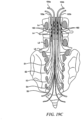
- Figure 19C illustrates the inferior portion of the spine, including the lower lumbar and sacral vertebrae, and associated nerve roots.
- Signals e.g., HF signals
- leads or pairs of leads can be positioned between adjacent roots to provide signals to a number of roots that is greater than the number of leads.
- a first pair of leads 152a, 154b, each having electrodes or electrode contacts 160 can be positioned along opposite sides of the S3 root to provide signals to at least the S2, S3 and S4 roots.
- a second pair of leads 152b, 154b can be placed alongside the L5 root to provide signals to the L5 root, the S1 root and optionally the L4 root.
- leads having similar (or other) structures can be placed along other roots.
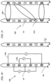
- Figures 20 and 21 illustrate a multi-channel, percutaneous lead arrangement 150 having first and second leads 152, 154 configured to deliver multiple therapy signals to a patient.
- Figure 20 illustrates how the lead arrangement 150 can be used generally to apply therapy signals to the dorsal column DC.
- Figure 21 illustrates how the lead arrangement 150 can be used generally to apply therapy signals to the dorsal root DR.
- the leads 152, 154 can cooperate to provide multiple types of therapy signals to the dorsal column DC and/or dorsal root DR of a patient.
- Each lead 152, 154 of the lead arrangement 150 includes a first arrangement 155 of electrodes, a second arrangement 157 of electrodes, and a third arrangement 159 of electrodes.
- the first and third arrangements 155, 159 include bipolar electrodes.
- the second arrangement 157 includes a tripolar electrode arrangement (e.g., a central cathode with anodes on either side). In such an embodiment, current can be controlled independently to adjust therapy for variations in electrode-to-nerve positioning.
- the leads 152, 154 can include other arrangements of electrodes.
- each lead 152, 154 of the lead arrangement 150 includes seven electrodes. In other embodiments, however, a lead can include one, two, three, four, five, or more electrodes.
- the first arrangement 155 of electrodes on one or both leads 152, 154 can apply an LF stimulation signal to the dorsal column DC to induce a sensation of paresthesia.
- the electric field of the stimulating signal can be generated by electrodes on a single lead so that the electric field is oriented along the length of the dorsal column DC.
- the electrodes of the first arrangement 155 of the first lead 152 create an electric field at the dorsal column DC to induce a sensation of paresthesia.
- the electrodes of the second arrangement 157 of one of the leads 152, 154 can generate an electric field of an HF blocking signal at the dorsal column DC to establish a block on the dorsal column DC.
- the electrodes of the second arrangement 157 can form a tripolar configuration to produce an HF blocking signal as shown in Figure 20 .
- the HF blocking signal can be generated using a lesser or greater number of electrodes of the second arrangement 157.
- the HF blocking signal can be applied to a dorsal root DR along at least some of the electrodes of the second arrangement 157 on both leads 152, 154.
- the middle electrodes of the second arrangement 157 on both leads 152, 154 cooperate to form an electric field. This electric field is oriented generally orthogonal to the electric field form from the tripolar electrode arrangement of Figure 20 .
- Figure 21 also shows a therapy signal channel between a first electrode 157a and a second electrode 157b.
- the therapy channel is angled with respect to the leads 152, 154. Such an angle may facilitate applying the therapy signal along the length of a dorsal root DR as the root branches from the dorsal column DC.
- Figure 22 illustrates a first treatment signal 2610 being applied to nerves of a dorsal column DC of a patient.
- the first treatment signal 2610 is an LF signal configured to up-regulate the nerves of the dorsal column DC to induce a sensation of paresthesia, and can be provided by a first portion of the pulse generator 101 described above with reference to Figure 1 .
- a second treatment signal 2620 is applied to a dorsal root DR of the patient subsequent to the initialization of the first treatment signal 2610.
- the second treatment signal 2620 is an HF signal configured to down-regulate the nerves of the dorsal root DR to establish a block on the nerves, and can be provided by a second portion of the pulse generator 101 described above with reference to Figure 1 .
- the paresthesia induced by the first treatment signal 2610 at least partially masks the onset response experienced by the patient when the second treatment signal 2620 is initiated.
- a third treatment signal 2630 is applied to the dorsal column DC after the second treatment signal 2620 is initiated.
- the third treatment signal 2630 is applied to the dorsal column DC after the second treatment signal 2620 establishes a block on the dorsal root DR.
- the third treatment signal 2630 is configured to establish a block on the dorsal column DC.
- a practitioner can implant multiple electrodes at the patient's spinal region, with at least one of the electrodes positioned to provide spinal cord stimulation, and at least one of the electrodes positioned to apply signals to the dorsal root or the dorsal root ganglion.
- the practitioner can then apply an LF signal to the first electrode to induce paresthesia and address pain suffered by the patient.
- the paresthesia may be sufficient to address the patient's pain symptoms, and accordingly, an HF signal need not be applied to the second electrode.
- an initial LF signal applied to the first electrode may not adequately address the patient's pain. In such instances, the amplitude of the signal supplied to the first electrode may be increased to produce paresthesia.
- the increase may be required because the position of the first electrode is not optimal, and/or because of patient-specific physiological effects.
- increasing the amplitude of the signal applied to the first electrode may, at the same time it causes paresthesia, separately cause patient discomfort. Accordingly, the practitioner can apply HF signals to the second electrode to block the patient discomfort, without the need for repositioning the first electrode. This arrangement can accordingly reduce the invasiveness of the implantation procedure.
- the patient may suffer from lower back pain.
- the lower back pain may be transmitted along afferent nerve fibers that enter the spinal column channel at the L5 vertebrae, which is below the end of the spinal cord.
- the practitioner may apply LF spinal cord stimulation at a higher spinal elevation, for example, at the T10 vertebrae.
- the paresthesia resulting from such LF signals may reduce pain somewhat, but not completely.
- the practitioner may additionally apply HF signals at the L5 location to block lower back pain sensations. In this instance, the HF signal is applied at a different spinal elevation than the low frequency signal.
- the patient may suffer from pain transmitted along several neural pathways that enter the spinal column at L1 (e.g., at the conus).
- the practitioner may apply HF signals at the conus, in combination with LF signals at a higher spinal elevation (e.g., T8, T9 or T10). This is unlike several existing stimulation techniques, which deliberately avoid the conus as an implantation/stimulation site.
Description
- The present disclosure relates generally to apparatuses for treating patient conditions, including chronic pain conditions via techniques that can include stimulating and blocking neuronal tissue associated with the spinal cord.
- Existing patient treatments include applying stimulation (e.g., up-regulating) signals to nerves, muscles or organs for treating a wide variety of medical disorders. Stimulation signal parameters (e.g., pulse width, frequency, and amplitude) are selected to initiate neural action potentials to be propagated along the nerve to an organ (e.g., brain or stomach).
- Down-regulating signals also can be applied to nerve fibers. Certain signal parameters can result in a signal that inhibits the nerve or blocks the propagation of action potentials along the nerve. In general, the nerve conduction block is applied to nerves with down-regulating signals selected to block the entire cross-section or part of the cross section of the nerves (e.g., afferent, efferent, myelinated, and non-myelinated fibers) at the site where the down-regulating signal is applied.
- In some systems, down-regulating signals are used to manage motor control over certain areas of a patient's body. For example, cryogenic nerve blocking of the vagus nerve to control motor activity is described in Dapoigny et al., "Vagal influence on colonic motor activity in conscious nonhuman primates," Am. J. Phvsiol., 262: G231 - G236 (1992). A cryogenic vagal block and the resulting effect on gastric emptying are described in Paterson CA, et al., "Determinants of Occurrence and Volume of Transpyloric Flow During Gastric Emptying of Liquids in Dogs: Importance of Vagal Input," Dig Dis Sci, (2000); 45:1509-1516.
- Applying up-regulating electrical energy to the spinal cord for the purpose of managing pain has been actively practiced since the 1960s. While a precise understanding of the interaction between the applied electrical energy and the nervous tissue is not fully appreciated, it is known that application of an electrical field to spinal nervous tissue can effectively mask certain types of pain transmitted from regions of the body associated with the stimulated tissue. Such spinal cord stimulation (SCS) for the treatment of chronic intractable pain was introduced by Shealy et al. (Anesth. Analg., 46, 489-491, 1967).
- More specifically, applying up-regulating electrical pulses to the spinal cord associated with regions of the body (e.g., dermatomes) afflicted with chronic pain can induce paresthesia, or a subjective sensation of numbness or tingling, in the afflicted bodily regions. This paresthesia can effectively mask the non-acute pain sensations perceived at the brain.
- Electrical energy, similar to that used to inhibit pain perception, also may be used to manage the symptoms of various motor disorders, for example, tremor, dystonia, spasticity, and the like. Motor spinal nervous tissue (e.g., nervous tissue from ventral nerve roots) transmits muscle/motor control signals. Sensory spinal nervous tissue (e.g., nervous tissue from dorsal nerve roots) transmits pain signals, as well as other sensory signals and proprioceptive signals.
- Corresponding dorsal and ventral nerve roots depart the spinal cord "separately." Laterally from the spinal cord, the nervous tissue of the dorsal and ventral nerve roots are mixed, or intertwined. Accordingly, electrical stimulation intended to manage and control one condition (e.g., pain) can inadvertently interfere with nerve transmission pathways in adjacent nervous tissue (e.g., motor nerves).
- Electrical energy is conventionally delivered through electrodes positioned on the dorsal column external to the dura layer surrounding a spinal cord. The electrodes are typically carried by a percutaneous lead, although a laminotomy lead also can be used. Percutaneous leads commonly have two or more electrodes and are positioned within an epidural space through the use of an insertion, or Touhy-like, needle. An example of an eight-electrode percutaneous lead is an OCTRODE® lead manufactured by Advanced Neuromodulation Systems, Inc. of Plano, Texas. Operationally, the insertion needle is passed through the skin, between the desired vertebrae, and into an epidural space located between a dural layer and the surrounding vertebrae. The stimulation lead is fed through the bore of the insertion needle and into the epidural space. Laminotomy leads generally have a wider, paddle-like shape, and are inserted via an incision rather than through a needle. For example, a small incision is made in the back of a patient to access the space between the dura and the surrounding vertebrae.
- According to the "gate-control" theory of Melzak and Wall, (Science, 150,971-978,1965), the suppression of pain sensations, accompanied by paresthesia, results from the activation of large cutaneous afferents (AO fibers). Because these nerve fibers are part of the dorsal root (DR) fiber that ascends in the dorsal column (DC), paresthetic sensations can be evoked by both DC and DR stimulation.
- The potential paresthesia coverage will strongly differ, however, depending on whether DC fibers or DR fibers are stimulated. When stimulating the DC fibers, the fibers corresponding to all dermatomes from the sacral ones up to the electrode level may be activated, thus resulting in broad paresthesia coverage. When stimulating DR fibers, however, the fibers will be activated in a limited number of rootlets close to the cathodal contact(s), thereby resulting in a paresthesia effect confined to one or two dermatomes at each body side.
- There are several problems with existing Spinal Cord Stimulation (SCS) therapy techniques. One is the difficulty of obtaining a permanent optimal position of the lead(s), to cover the painful dermatomes with paresthesia. Another problem is the usually small range of stimulation amplitudes between the perception threshold (i.e., the threshold at which paresthesia is effected) and the discomfort threshold (i.e., the threshold at which the patient experiences pain or other discomfort), often preventing a complete coverage of the painful area by the paresthesia needed for maximum therapeutic effect (Holsheimer, Neurosurgery, 40, 5, 990-999, 1997).
- The invention is defined in the appended claims. Any methods disclosed hereinafter do not form part of the scope of the invention, and are merely provided for illustrative purposes
- In some cases, low frequency signals are applied to the dorsal column to address chronic patient pain associated with a peripheral site. However, the dorsal roots also can be stimulated when low frequency stimulation is applied to the dorsal column to produce the paresthesia necessary to overcome the chronic pain. For example, the dorsal roots may be stimulated if the stimulation leads are placed too close to the dorsal root, and/or if the amplitude of the low frequency signal is increased to the discomfort threshold. The discomfort threshold at the dorsal root can be reached before the parethesia threshold (i.e., the threshold at which paresthesia is affected) is reached at the dorsal column. Hence, the clinician has limited freedom to increase the amplitude of the signal at the dorsal column to achieve the desired paresthesia effect, before discomfort is felt due to the dorsal root stimulation.
- Aspects of the present disclosure are directed to managing chronic pain through the application of electrical energy to selected nervous tissue and, in particular embodiments, to systems for treating chronic pain by applying neuromodulation therapies to one or more regions of neuronal tissue in the spinal region. As the term is used herein, the "spinal region" includes the nerves of the dorsal column, dorsal roots, and the dorsal roots ganglion, which are located within the dural layer.
- A method for treating patient pain includes applying a first electrical signal to a first target location (e.g., a dorsal column) of the patient's spinal cord region at a frequency in a first frequency range of up to about 1,500 Hz. The method further includes applying a second electrical signal to a second target location (e.g., at least one of a dorsal root and a dorsal root ganglion) of the patient's spinal cord region at a frequency in a second frequency range of from about 2,500 Hz to about 100,000 Hz. The second frequency range can be from about 2,500 Hz to about 20,000 Hz, or about 3,000 Hz to about 10,000 Hz. Further methods include inducing paresthesia by applying the first electrical signal, and at least partially blocking patient discomfort resulting from applying the first electrical signal by applying the second electrical signal.
- A method includes implanting a first electrode proximate to a dorsal column of the patient's spinal cord region, and implanting a second electrode proximate to at least one of a dorsal root and a dorsal root ganglion of the patient's spinal cord region. The method can further include applying a first electrical signal to the first electrode at a frequency in a first frequency range of up to about 1,500 Hz. If the patient experiences discomfort, a second electrical signal is applied to the second electrode at a frequency in a second frequency range of from about 2,500 Hz to about 100,000 Hz in combination with applying the first electrical signal, and without repositioning the first electrode. The second frequency range can be from about 2,500 Hz to about 20,000 Hz, or about 3,000 Hz to about 10,000 Hz.
WO2006/007048 discloses a neuromodulation system operating at a frequency range between 2 Hz to 2500 Hz. - Further embodiments, not forming part of the claimed invention, are directed to systems for treating patient pain. In a particular embodiment, the system can include a controller having instructions for directing first electrical signals in a first frequency range of up to about 1,500 Hz, and directing second electrical signals in a second frequency range of from about 2,500 Hz to about 100,000 Hz. In particular embodiments, the second frequency range can be from about 2,500 Hz to about 20,000 Hz, or about 3,000 Hz to about 10,000 Hz. A first electrical signal delivery device can be electrically coupled to the controller to receive the first electrical signals, and can be configured to be positioned proximate to a first target location of the patient's spinal cord region (e.g., the dorsal column). A second electrical signal delivery device can be electrically coupled to the controller to receive the second electrical signals, and can be configured to be positioned proximate to a second target location of the patient's spinal cord region (e.g., at least one of a dorsal root and a dorsal root ganglion of the patient's spinal cord region).
-
-
Figure 1 is a schematic diagram of an implantable spinal stimulator with an electrode array applied to the spine in accordance with an embodiment of the present disclosure. -
Figure 2 is a schematic diagram of an implantable spinal stimulator with percutaneous leads and electrodes applied to the spine in accordance with another embodiment of the present disclosure. -
Figure 3 is a partially schematic cross-sectional view of a spinal column taken along line 3-3 ofFigure 1 in accordance with an embodiment of the present disclosure. -
Figure 4 illustrates examples of biphasic, charge balanced, square wave pulses applied to electrodes on different channels of a therapy system in accordance with an embodiment of the present disclosure. -
Figure 5 illustrates examples of biphasic, charge balanced, sinusoidal wave pulses applied to electrodes on different channels of a therapy system in accordance with an embodiment of the present disclosure. -
Figure 6 is a schematic depiction of an example blocking signal applied to the dorsal column in accordance with an embodiment of the present disclosure. -
Figure 7 is a schematic depiction of an example high frequency (HF) blocking signal applied to the dorsal root in accordance with an embodiment of the present disclosure. -
Figure 8 schematically depicts the amplitude of an example low frequency (LF) stimulation signal likely to induce paresthesia, and the amplitude of the LF stimulation signal likely to induce patient discomfort at a given electrode spacing in accordance with an embodiment of the present disclosure. -
Figure 9 is a schematic view of an HF blocking signal applied to the dorsal root of a patient and an LF stimulating signal applied to the dorsal column in accordance with an embodiment of the present disclosure. -
Figure 10 is a schematic diagram of an example blocking signal, which has an amplitude that is gradually increased to an operating amplitude over a finite period of time in accordance with an embodiment of the present disclosure. -
Figure 11A is a schematic graph generally showing the changes in frequency during application of a therapy in accordance with an embodiment of the present disclosure. -
Figure 11B is a schematic graph generally showing the changes in amplitude during application of the therapy ofFigure 11A in accordance with an embodiment of the present disclosure. -
Figure 11C is a schematic graph generally showing the changes in charge/phase during application of the therapy ofFigure 11A in accordance with an embodiment of the present disclosure. -
Figure 12 is a schematic depiction of an example blocking signal initially having a high frequency (e.g., about 30-50 KHz) and a high amplitude (e.g., about 1520 mA) in accordance with an embodiment of the present disclosure. -
Figure 13 shows the blocking signal ofFigure 12 with an initial ramp-up period in accordance with an embodiment of the present disclosure. -
Figure 14 is a schematic depiction of an example LF signal and an example HF signal indicating a representative timing strategy for applying the LF and HF signals in accordance with an embodiment of the present disclosure. -
Figures 15-18 are schematic block diagrams of representative electrode arrays including four electrodes implanted at the spinal cord of a patient in accordance with an embodiment of the present disclosure. -
Figure 19A is a schematic block diagram of a lead configuration in which first and second percutaneous leads are implanted within the patient together in accordance with an embodiment of the present disclosure. -
Figure 19B is a schematic block diagram of a lead configuration in which a first percutaneous lead is implanted within the patient adjacent the dorsal column and a second percutaneous lead is implanted within the patient adjacent the dorsal root in accordance with an embodiment of the present disclosure. -
Figure 19C is a partially schematic illustration of percutaneous leads positioned at lumbar locations in accordance with embodiments of the disclosure. -
Figure 20 is a schematic block diagram of a multi-channel, percutaneous lead arrangement having first and second leads configured to deliver multiple therapy signals to a dorsal column of a patient in accordance with an embodiment of the present disclosure. -
Figure 21 is a schematic block diagram of a multi-channel, percutaneous lead arrangement having first and second leads configured to deliver multiple therapy signals to a dorsal root of a patient in accordance with an embodiment of the present disclosure. -
Figure 22 illustrates a first treatment signal being applied to nerves of a dorsal column of a patient in accordance with an embodiment of the present disclosure. -
Figure 1 schematically illustrates arepresentative therapy system 100 for providing relief from chronic pain, arranged relative to the general anatomy of a spinal cord SC of a patient. Thetherapy system 100 can include a controller (e.g., a pulse generator 101) implanted subcutaneously within the patient. Thepulse generator 101 is attached via alead body 102 to an electrode array 103 or other signal delivery device, which is implanted in close proximity to the spinal cord SC. The electrode array 103 can include multiple electrodes or electrode contacts carried by a support substrate. Thepulse generator 101 or other controller transmits instructions and power to the electrode array 103 via thelead body 102 to apply therapy signals (e.g., electrical impulses) to the nerve fibers of the patient to up-regulate (e.g., stimulate) and/or down-regulate (e.g., block or partially block) the nerves. Accordingly, thepulse generator 101 can include a computer-readable medium containing the instructions. Thepulse generator 101 and/or other elements of thesystem 100 can include one or more processors, memories and/or input/output devices. Thepulse generator 101 can include multiple portions, e.g., for directing signals in accordance with multiple signal delivery parameters, housed in a single housing (as shown inFigure 1 ) or in multiple housings. - In some embodiments, the
pulse generator 101 can obtain power to generate the therapy signals from anexternal power source 105. Theexternal power source 105, which is arranged external to the patient, can transmit power to the implantedpulse generator 101 using electromagnetic induction (e.g., RF signals). For example, theexternal power source 105 can include anexternal coil 106 that communicates with a corresponding coil (not shown) within theimplantable pulse generator 101. Theexternal power source 105 can be portable for ease of use. - In another embodiment, the
pulse generator 101 can obtain the power to generate therapy signals from an internal power source. For example, the implantedpulse generator 101 can include a non-rechargeable battery or a rechargeable battery to provide the power. When the internal power source includes a rechargeable battery, theexternal power source 105 can be used to recharge the battery. Theexternal power source 105 in turn can be recharged from a suitable power source e.g., via astandard power plug 107. - In still further embodiments, an external programmer (not shown) can communicate with the
implantable pulse generator 101 via electromagnetic induction. Accordingly, a practitioner can update the therapy instructions provided by thepulse generator 101. Optionally, the patient may also have control over at least some therapy functions, e.g., starting and/or stopping thepulse generator 101. -
Figure 2 illustrates another therapy system 200 in which theimplantable pulse generator 101 is connected to percutaneouslead bodies electrodes 110. The leads 108, 109 andelectrodes 110 are shown in a bipolar configuration with twoelectrodes 110 carried by each lead 108, 109. In other embodiments, however, theleads electrodes 110 of the percutaneous leads 108,109) can be arranged adjacent different nerve fibers within the patient to enable the application of different types of therapy, as is discussed further below. -
Figure 3 is a cross-sectional illustration of a spinal region SR that includes the spinal cord SC and an adjacent vertebra VT (based generally on information from Crossman and Neary, "Neuroanatomy," 1995 (publ. by Churchill Livingstone)), along with selected representative locations for representative leads 108 (shown asleads 108a-108d) in accordance with several embodiments of the disclosure. The spinal cord SC is situated between a ventrally located vertebral body WB and a dorsally located vertebral body DVB that includes atransverse process 198 andspinous process 197. Arrows V and D identify ventral and dorsal directions, respectively. In particular embodiments, the vertebra VT and leads can be at T10 or T11 (e.g., for axial low back pain or leg pain) and in other embodiments, the leads can be placed at other locations. The spinal cord SC itself is located within the dura mater DM, which also surrounds portions of the nerves exiting the spinal cord SC, including the dorsal roots DR, dorsal root ganglia G and ventral roots VR. The spinal cord SC is illustrated as having identifiable areas of afferent and efferent fibers including ascending pathway areas AP and descending pathway areas DP. - The leads are generally positioned to stimulate tactile fibers and to avoid stimulating fibers associated with nociceptive pain transmission. In a particular embodiment, a
lead 108a (e.g., a first lead) can be positioned centrally in a lateral direction (e.g., aligned with the spinal cord midline ML) to provide signals directly to the dorsal column DC of spinal cord SC. In other embodiments, the first lead can be located laterally from the midline ML. For example, single or paired leads can be positioned just off the spinal cord midline ML (as indicated byleads 108b) to provide signals to the dorsal column DC. One or more other leads (e.g., second leads) can be positioned proximate to the dorsal root DR or dorsal root entry zone DREZ (e.g., 1-4 mm from the spinal cord midline ML, as indicated generally by lead 108c), and/or proximate to the dorsal root ganglion G (as indicated by lead 108d). Other suitable locations for the second lead include the "gutter," also located laterally from the midline ML. In still further embodiments, theleads 108 may have other locations proximate to the spinal cord SC and/or proximate to other target neural populations e.g., laterally from the midline ML and medially from the dorsal root ganglion 194. For example, the leads can be located subdurally rather epidurally, as shown in dashed lines formidline lead 108a and off-midline leads 108b. The practitioner may select any of a variety of combinations of the foregoing locations, depending on the particular patient's needs and condition. In at least some embodiments, the practitioner can place two leads, each positioned to direct signals to a different target location (e.g., neural population) of the patient's spinal cord SC. In other embodiments, a single lead may have electrodes positioned at two or more target locations. In either case, individual electrodes can deliver signals with different characteristics to different neural populations to achieve a beneficial effect for the patient. - In general, different types of therapy signals can be applied to the nerve fibers of a patient to different effect. For example, applying a low-frequency (LF) therapy signal to the nerve fibers of a patient can stimulate the nerve fibers to create an effect known in the art as "paresthesia," which creates a sensation of numbness in the patient. This paresthesia effect can mask chronic pain, providing relief to the patient. Such an application of therapy signals is generally known as Spinal Cord Stimulation (SCS) therapy. In a particular embodiment of the present disclosure, the LF signal can have a frequency in the range of up to about 1,500 Hz, and a pulse width equal to or less than half of the period of the signal. In a particular embodiment, the LF signal can have a frequency in the range of from about 40 Hz to about 500 Hz.
- Applying a high-frequency (HF) therapy signal to the nerves can produce a block or partial block on the nerves. Accordingly, as used herein, the term "block" refers generally to an at least partial block (e.g., a partial or complete block), and the term "blocking signal" refers generally to a signal that creates an at least partial block. In addition, while it is believed that the block inhibits or prevents the transmission of neural signals, a desired effect on the patient (e.g., pain reduction) is not necessarily limited to such a mechanism, and in at least some embodiments, pain reduction may be achieved by one or more other mechanisms. This block inhibits and/or prevents excitatory responses from reaching the brain of the patient. Typically, the HF therapy signal includes a biphasic signal. In a particular embodiment, the HF therapy signal is a biphasic (alternating current) signal having a 50% duty cycle and a frequency in the range of from about 2,500 Hz to about 100,000 Hz. In particular embodiments, the HF signal can have a frequency in the range of from about 2,500 Hz to about 20,000 Hz, and in further particular embodiments, about 3,000 Hz to about 10,000 Hz.
- Representative examples of HF signal waveforms that can be applied to the dorsal column DC (
Figure 3 ) are shown inFigures 4 and5 . The signal waveforms shown inFigure 4 include biphasic, charge balanced, square wave pulses. In the example shown, afirst waveform 400 is applied to a first signal channel C1 and asecond waveform 450 is applied to a second signal channel C2. In a particular embodiment, the waveform on the first signal channel C1 is interlaced with the waveform on the second signal channel C2 to minimize interaction between thesignals Figure 4 can be used. For example,Figure 5 illustrates biphasic, charge balanced,sinusoidal pulses - Detailed treatment processes for administering therapy signals for chronic pain management are described below. In certain embodiments, a physician or other practitioner can choose to combine two or more of the treatment processes described below for administering therapy for chronic pain management. The combination of the different types of therapy can provide pain relief on multiple fronts, providing extended coverage to the patient. For example, in one embodiment, multiple treatment processes can be applied to a patient simultaneously. In other embodiments, the therapies can be combined, but chronologically spaced, or offset, which can also have advantages. For example, as noted in further detail later, one therapy signal can be used to facilitate the initialization and/or the maintenance of another therapy signal.
- A representative first treatment process for administering therapy for chronic pain management includes applying an HF blocking signal directly to the dorsal column DC of the patient. For example,
Figure 6 is a schematic depiction of a representativeHF blocking signal 600 applied to the dorsal column DC. This HF blocking signal can be applied to the dorsal column DC in place of an LF stimulation signal to replace the pain relief provided by the paresthesia. - In general, the HF
stimulation blocking signal 600 is applied to the dorsal column DC to establish a partial or total neuronal block at the dorsal column DC sufficient to block the chronic pain felt by the patient. The HF therapy signal can be applied to one or more select regions (e.g., vertebral levels) of the dorsal column DC to block transmission of pain signals from lower dermatomes. The HF blocking signal can inhibit or prevent the sensation of pain (e.g., to effect anesthesia) in the dermatomes corresponding to the selected regions. - In a representative second treatment process for administering therapy for chronic pain management, an HF blocking signal is applied to one or more dorsal roots DR and/or dorsal root ganglion(s) G of a patient, instead of directly to the dorsal column DC.
Figure 7 is a schematic depiction of an exampleHF blocking signal 700 applied to the dorsal root DR. Blocking at the dorsal root DR and/or the dorsal root ganglion G facilitates blocking sensation signals associated with one or more select regions of the body. In contrast, blocking at the dorsal column DC generally blocks only tactile and proprioceptive signals, generally at all dermatomes associated with sections of the dorsal column DC located below the blocking electrodes. - Arranging the electrodes (e.g., the electrodes carried by the array 103 shown in
Figure 1 or theelectrodes 110 shown inFigure 2 ) at the dorsal root DR and/or dorsal root ganglion G can enhance the range and effectiveness of the therapy signals. At such locations, the CSF fluid layer is not as thick as it is at the dorsal column DC, which can allow more current to flow to the spinal region. The CSF fluid layer is thicker closer to the dorsal column DC, which can shunt much of the current before the current reaches the dorsal column DC. By positioning the electrodes away from the dorsal column DC, it is expected that an electrical block of the nerve fibers may be established with less power. - In addition, sensory nerve responses typically proceed through the dorsal roots DR to the dorsal column DC, whereas motor nerve responses proceed through the ventral roots VR (see
Figure 3 ) to the spinal cord SC. Applying therapy signals to the dorsal root DR, therefore, can facilitate blocking of sensory responses (e.g., pain) without decreasing or eliminating the transmission of motor control impulses. - In a third treatment process for administering therapy for chronic pain management, an HF blocking signal can be applied to the peripheral nerves of the patient (e.g., the nerves distal of the spinal cord SC). For example, an HF blocking signal can be applied to the somatic nerves of the patient. In another embodiment, the HF blocking signal can be applied to the autonomic nerves of the patient. Applying the HF block to the peripheral nerves can enable placement of the electrodes away from the spinal cord SC and the spinal fluid, and can therefore reduce the likelihood for interference with spinal function.
- Other treatment processes for administering therapy for chronic pain management combine the application of an HF blocking signal with the process of applying an LF stimulating signal to the dorsal column DC of the patient to induce paresthesia. In general, the HF blocking signal can facilitate the inducement of paresthesia by alleviating patient discomfort resulting from the application of the LF stimulation signal.
- The application of an LF stimulation signal to the dorsal column DC can induce paresthesia and/or induce patient discomfort, depending on the distance between the electrode(s) and the spinal cord (e.g., the thickness of the intermediate cerebral spinal fluid layer). As used herein, the term "discomfort" refers generally to an unpleasant, undesirable, uncomfortable and/or unwanted sensation or other response. The term includes, but is not limited to, pain. Typically, in conventional SCS treatment, patient discomfort results from the inadvertent application of the electric field produced by the electrode(s) to an adjacent dorsal root DR. In general, the greater the distance between the electrode and the spinal cord, the greater the likelihood that the electric field will interact with the dorsal root DR to stimulate pain sensations on the dorsal root DR, thus causing discomfort and/or pain as the signal amplitude is increased.
-
Figure 8 schematically depicts the amplitude of an LF stimulation signal likely to induce paresthesia (represented by threshold curve Tp) and the amplitude of the LF stimulation signal likely to induce patient discomfort (represented by threshold curve TD) as a function of spacing between the electrodes and the spinal cord.Figure 8 is not intended as an exact plot of amplitude as a function of the spacing, but rather is intended to illustrate the general relationship amongst the paresthesia threshold Tp, the patient discomfort threshold TD, and the spacing. - As shown in
Figure 8 , when the electrodes are spaced relatively close to the spinal cord (e.g., when the spacing is less than about distance X), the electric field created by the electrode(s) induces paresthesia before causing discomfort. However, when the electrodes are spaced farther from the spinal cord (e.g., when the spacing is greater than about distance X), the LF stimulation signal can stimulate the dorsal root DR fibers, thereby potentially causing discomfort, before stimulating the dorsal column fibers at a level sufficient to induce paresthesia. The paresthesia threshold Tp and the patient discomfort threshold TD cross at the electrode spacing distance X, which is approximately 2 mm in at least some embodiments, and can vary depending on factors that include signal delivery parameters. Further details regarding the relationship amongst electrode spacing, paresthesia, and pain can be found, e.g., in Effectiveness of Spinal Cord Stimulation in the Management of Chronic Pain: Analysis of Technical Drawbacks and Solutions by Jan Holsheimer (Neurosurgery, Vol. 40, No. 5, May 1997). - Some combination treatment processes in accordance with embodiments of the disclosure for administering therapy for chronic pain management use an HF blocking signal to inhibit the discomfort sensation produced when the LF signal amplitude reaches the discomfort threshold TD, thereby enabling the amplitude of the LF signal to be increased further to the paresthesia threshold Tp. This in turn can allow the LF signal to be effective, even if it is provided by an electrode that would otherwise be too far away from the target nerve region (e.g., the dorsal column) to produce paresthesia without also producing discomfort. Other combination treatment processes augment the pain relief provided by paresthesia with the pain relief provided by blocking different sections of the spinal region, as will be discussed later.
- A representative fourth treatment process for administering therapy for chronic pain management applies an HF blocking signal to the dorsal root DR (and/or dorsal root ganglion G) while applying the LF stimulating signal at the dorsal column DC. As used herein, the term "dorsal root" can include the dorsal root itself, the dorsal root entry region, and the conus.
Figure 9 is a schematic illustration of anHF blocking signal 900 applied to the dorsal root DR of a patient, and anLF stimulating signal 950 applied to the dorsal column DC. The HF signal can establish a block on the dorsal root DR that inhibits the transmission to the brain of pain sensations induced by the electric field of the LF stimulation signal. - The
HF blocking signal 900 is applied to the dorsal root DR prior to application of theLF stimulating signal 950 to the dorsal column DC. In other embodiments, however, theHF blocking signal 900 can be applied at generally the same time as or after theLF stimulating signal 950 is applied to the dorsal column DC. In one embodiment, theLF stimulation signal 950 can be initiated with a low-level amplitude that is subsequently ramped up to a suitable operating amplitude. - In other embodiments, the HF blocking signal applied to the dorsal root DR augments the pain relief provided by the paresthesia. For example, blocking the dorsal root DR is expected to block peripheral pain (e.g., any peripheral pain) from being transmitted through the dorsal root DR. This can include not only discomfort caused by the LF signal, but also the pain that the LF signal is expected to address.
- A representative fifth treatment process for administering therapy for chronic pain management applies an HF blocking signal at a first section of the dorsal column DC while applying the LF stimulating signal at a second section the dorsal column DC. The LF stimulating signal is expected to induce a sensation of paresthesia in dermatomes (e.g., all dermatomes) associated with the second section of the dorsal column DC and lower sections (e.g., all lower sections). The HF blocking signal is expected to block excitatory responses produced at the first section and lower sections from reaching the brain.
- The HF blocking signal is applied to the dorsal column DC prior to application of the LF stimulating signal to the dorsal column DC. In other embodiments, however, the HF blocking signal can be applied at substantially the same time as or after the LF stimulating signal is applied. In one embodiment, the LF stimulation signal can be initiated with a low-level amplitude that is subsequently ramped up to a suitable operating amplitude.
- In other embodiments, the HF blocking signal applied to the dorsal column DC augments the pain relief provided by the paresthesia. For example, the LF stimulating signal can boost nerve responses that inhibit the sensation of pain and the HF blocking signal can inhibit nerve responses that transmit pain signals to the brain.
- In general, the HF signal can be applied to the dorsal column DC above (superior) or below (inferior) the site at which the LF signal is applied. Signals applied to the dorsal column DC will tend to induce action potentials in both directions along the target sensory signal route, e.g., toward the brain (orthodromic) and away from the brain (antidromic). If the orthodromic LF signal creates a pleasant (or at least non-objectionable) sensation, such as tingling, that masks the target pain, then there may be no need for an HF signal applied to the dorsal column DC. However, if the LF signal creates an unpleasant sensation (an orthodromic signal), and the corresponding antidromic signal acts to mitigate the target pain, then an HF signal may be applied superior to the LF stimulation site to suppress the unpleasant sensation caused by the orthodromic signal, while having no effect on the beneficial antidromic signal. Accordingly, the patient can be outfitted with a device that includes an LF signal generator coupled to electrical contacts at the dorsal column, and an HF signal generator coupled to electrical contacts located superiorly on the dorsal column DC. In particular embodiments, the HF signal generator is activated if (a) the paresthesia created by the LF signal is objectionable to the patient, and (b) the antidromic action potentials created by the LF signal reduce the target pain.
- The HF signals can be applied to the dorsal column DC at a location inferior to where the LF signals are applied. In this case, it is assumed that the antidromic signals produced by the LF signals do not contribute (or do not contribute significantly) to reducing the target pain. Accordingly, applying HF signals at an inferior location, which is expected to block such antidromic signals, is not expected to impact the effectiveness of the LF signals, e.g., the orthodromic paresthesia effect. It is further assumed, based on recent evidence, that dorsal column DC fibers transmit pain, in contrast to more traditional models which posit that pain travels through the spinothalamic tract. Based on this assumption, blocking orthodromic pain signals passing along the dorsal column is expected to reduce the target pain.
- In general, the
therapy systems 100, 200 (Figures 1 and2 ) can be utilized to provide chronic pain management to patients using one of the above described therapy options, or one or more combinations thereof. The following treatment parameters are representative of treatment parameters in accordance with particular embodiments. - In general, HF blocking signals can have a frequency ranging between about 2,500 Hz and about 100,000 Hz. In a particular embodiment, the HF blocking signal has a frequency ranging between about 2,500 Hz and about 20,000 Hz and in another particular embodiment, between about 3,000 Hz and about 10,000 Hz. In other particular embodiments, the HF signal has a frequency of greater than 10,000 Hz. Frequencies above 10,000 Hz may result in shorter transition times, e.g., shorter times required to establish a block. The current of the HF blocking signals ranges from about 2 mA to about 20 mA. In a particular embodiment, the current of a representative HF blocking signal is about 5-10 mA.
- After an HF blocking signal has been initialized, the amplitude of the blocking signal can be reduced from a first operating level to a second, lower operating level without affecting the sensory experience of the patient. For example, in particular embodiments, the amplitude of the HF blocking signal can be reduced by about 10-30% after initialization without affecting the established block. Such a result can advantageously decrease the amount of power required to operate the
therapy system 100, 200 (Figures 1 and2 ). For example, decreasing the operating power can increase the battery life of thepulse generator 101 or otherwise decrease the drain on the power source. - Therapy can be applied in a discontinuous fashion so as to include periods when the therapy is applied, and periods when the therapy is terminated according to a duty cycle. Therapy application periods can range from a few seconds to a few hours. In other embodiments, the duty cycle of a therapy signal can extend over a few milliseconds.
- When HF blocking signals are initially applied to nerve fibers, the patient can experience an onset response before the block takes effect. An onset response is induced by a brief activation of the nerve fibers resulting in sudden pain and/or involuntary muscle contractions. Such an onset response can occur regardless of whether the therapy signals are applied to the dorsal column DC, the dorsal root DR, the dorsal root ganglions G, or to the peripheral nerves of the patient.
- In order to alleviate these symptoms, various initialization procedures can be used as described below. For example, the nerve activation caused by initializing the blocking signal can be mitigated by adjusting the signal parameters (e.g., amplitude and/or frequency) of the blocking signal. Alternatively, patient discomfort caused by the onset response can be masked by applying additional pain management therapy.
- As the term is used herein, mitigation of an onset response refers generally to a decrease in the otherwise resulting activation of the nerve to which the blocking signal is being applied.
- A first initialization procedure for mitigating patient onset response includes gradually ramping up the amplitude of the blocking signal being applied to the nerve. As the term is used herein, the amplitude of the blocking signal can refer to the current amplitude and/or the voltage amplitude of the signal since a direct relationship exists between the current and the voltage of the blocking signal.
- By starting the signal at a lower amplitude, fewer nerve fibers are affected and stimulated initially. As the amplitude is increased, additional nerve fibers are stimulated as the block is established at the previous nerve fibers. The total number of nerve fibers activated at any one time, therefore, is decreased when compared with an un-ramped initialization. Patient discomfort that may be caused by the stimulated fibers is likewise expected to be mitigated.
- For example, in
Figure 10 , the amplitude and/or frequency ofrepresentative blocking signal 1000 is gradually increased to an operating amplitude OA over a finite period of time. In one embodiment, the amplitude of thewaveform 1000 is increased over a period of a few seconds. In other embodiments, however, the amplitude and/or frequency can be increased over a greater or lesser period of a time (e.g., a few minutes or a few milliseconds). In still further embodiments, the amplitude and/or frequency can be decreased over time, as is discussed further below with reference toFigures 11A-11C . - Referring to
Figures 11A-11C , a second initialization procedure for reducing the onset response to treatment can include at least two phases, one in which the applied frequency and/or amplitude are above general operating levels, and one in which the frequency and/or amplitude are reduced to operating levels. These phases, as well as additional (and in some cases, optional) phases are described below. - The second initialization procedure can include an optional onset phase PO during which the frequency of the blocking signal is maintained at a constant level Fl (see
Figure 11A ) and the amplitude of the blocking signal is ramped up from a low amplitude Al to a high amplitude A2 (seeFigure 11B ). - In a first phase P1, a blocking signal having a frequency Fl and amplitude A2 greater than the general operating frequency FO1 and operating amplitude AO1 is applied to a nerve. For example, a blocking signal having a frequency in the range of about 2,500 Hz to above 20 KHz and an amplitude up to about 20 mA can be applied during the first phase P1.
- In some embodiments, the application of the blocking signal having a very high frequency Fl and a high amplitude A2 rapidly results in a block on the nerve. In other embodiments, however, the second initialization procedure can include an optional transition phase P2 during which a block is established (i.e., during which the signal increases in strength above the threshold T1). Even when the transition phase P2 is utilized, however, the blocking signal establishes a block on the nerve more rapidly than would a signal that simply has the operating frequency and operating amplitude.
- During the transition phase P2, the frequency of the blocking signal is decreased from the very high frequency Fl to a frequency F2 (see
Figure 11A ). Frequency F2 is lower than frequency Fl, but still significantly higher than the operating frequency FO. Decreasing the frequency increases the charge per phase and hence the strength of the blocking signal (seeFigure 11C ). The frequency is lowered until the signal strength crosses the blocking threshold T1. The amplitude may be further increased as well during the transition phase P2. - In a subsequent phase P3, the frequency and amplitude of the blocking signal can be reduced from a level at which the block is established to first operating levels (e.g., FO1, AO1 shown in
Figure 11B ). In one embodiment, a block is established when the charge per phase of the blocking signal passes above a blocking threshold T1 (seeFigure 11C ). Decreasing the amplitude of the blocking signal lessens the drain on the power source. Decreasing the frequency increases the charge per phase (e.g., the stimulation applied to the nerve fibers) to compensate for the reduction in amplitude. A practitioner begins ramping down the frequency and the amplitude concurrently. In other embodiments, however, the amplitude and frequency can be ramped down at different times. - An optional phase P4 includes decreasing the amplitude of the signal from the first operating level AO1 to a different operating level AO2 after the block is established (see
Figure 11B ). Decreasing the amplitude lowers the charge per phase (seeFigure 11C ). The block can be maintained, even if the charge per phase drops below the first threshold T1, as long as the charge per phase does not drop below a second threshold T2 (seeFigure 11C ). Typically, threshold T2 is 10-30% less than the threshold T1. -
Figure 12 is a schematic depiction of anexample blocking signal 1200 initially having a high frequency Fl (e.g., about 30-50 KHz) and a high amplitude A2 (e.g., about 15-20 mA). In the example shown, theblocking signal 1200 is a biphasic, charge balanced, square waveform. In other embodiments, however, theblocking signal 1200 can include any desired waveform. When the block on the nerve is established, the amplitude of theblocking signal 1200 is ramped down to an appropriate operating level AO (e.g., about 5-10 mA). As further shown inFigure 12 , the frequency of theblocking signal 1200 also can be decreased to an appropriate operating level FO (e.g. about 3-10 KHz). -
Figure 13 shows theblocking signal 1200 having an initial ramp-up period shown at 1200a, during which the signal amplitude is increased to a maximum amplitude MA. Ramping up the amplitude of the signal can allow the signal to be initiated safely with reduced or non-existent patient discomfort. In other embodiments, however, the onset phase P0 can be skipped and the very high amplitude A2 of the blocking signal can be applied from the beginning. - As the term is used herein, masking of an onset response refers generally to a decrease in the discomfort of the patient otherwise resulting from an onset response, without affecting activation of the nerve to which the blocking signal is being applied.
- Referring to
Figure 14 , paresthesia induced by an LF stimulating signal applied to the dorsal column DC can mitigate the onset response of an HF blocking signal applied to the dorsal root DR. The low-level paresthesia, while not strong enough to control the chronic pain of the patient, can alleviate some or all of the discomfort experienced by the patient as a result of the initialization of the HF blocking signal. Examples of the relative timing for the therapy signals are shown inFigure 14 . - As shown in
Figure 14 , anLF stimulating signal 1450 having a low amplitude and a low frequency (e.g., in the range of about 40 Hz to about 250 Hz) is applied to the dorsal column DC of a patient to induce paresthesia. Next, anHF blocking signal 1400 having a high frequency (e.g., ranging from about 2,500 Hz to about 100,000 Hz, and in a particular embodiment, from about 2,500 Hz to about 20,000 Hz, and in a further particular embodiment, about 2,500 Hz to about 10,000 Hz) is applied to the dorsal root DR of the patient. The paresthesia induced by stimulating the dorsal column DC can enhance patient comfort while the partial or complete HF block is established at the dorsal root DR. In a representative example, an LF signal is applied to the dorsal column DC for a period of several seconds before applying the HF signal, at least up to an amplitude below that which causes discomfort and/or pain. In particular embodiments (e.g., in cases for which the HF blocking signal by itself has a sufficient therapeutic effect), the LF signal can be halted once the HF signal is established and the period for experiencing an onset response has passed. In a representative embodiment, this time period can be from about 5 seconds to about 5 minutes. The LF signal can then be re-established for a short period the next time an HF signal is initiated to again reduce or eliminate the onset response. In this manner, the onset response can be controlled without requiring a continuous (and therefore power consuming) LF signal. This arrangement can be used when the LF signal is applied at a location superior to the HF signal location, e.g., when both the LF and HF signals are applied to the dorsal column DC, or when the LF signal is applied to the dorsal column DC above a dorsal root DR location at which the HF signal is applied. - One or more pharmaceutical drugs affecting the pain neural transmission synapse or neuromuscular junction also can be given to the patient prior to initiating a therapy signal, such as an HF blocking signal. For example, bupivacaine and/or other suitable local anesthetics may be used in this regard, when injected epidurally. The various classes of analgesics used for epidural and spinal block include local anesthetics, opioids, adrenergic agonists, and cholinergic agonists. Local anesthetics inhibit neural conduction by reversibly blocking conductance in axonal sodium channels. Opioids exert their effect by reversibly binding to opioid receptors in the dorsal horn of the spinal cord. Alpha-2 adrenergic agents interact with alpha-2 adrenergic receptors in the spinal cord, and cholinergic agonists produce analgesia by increasing the concentration of acetylcholine proximate to muscarinic and nicotinic receptors in the superficial layers of the dorsal horn of the spinal cord. The pharmacological agent can be delivered via the same device that supplies the electrical signals, or the agent can be delivered via a separate device. In a particular embodiment, PLGA or another suitable polymer can be used to exude the agent.
-
Figures 15-18 illustrate different design variations that include an electrode array having four electrodes. In other embodiments, arrays can include a greater or lesser number of electrodes arranged in the same or other patterns. In a particular embodiment, an array can contain two electrodes. In another embodiment, an array can contain three electrodes. In yet another embodiment, an array can contain up to sixteen or more electrodes. Increasing the number of electrodes increases the number of channel vectors which can be utilized during therapy, thereby broadening the types of therapy applied and/or the regions over which the therapy is applied. -
Figure 15 illustrates anexample electrode array 119 including fourelectrodes Figure 15 , a first therapy signal (e.g., for affecting paresthesia at the dorsal column DC) is applied via a first output channel C1 (shown schematically) of thearray 119 that extends along the dorsal column DC and can include a first pair ofelectrodes array 119 that extends at an angle (e.g., 10°, 30°, 60°, 90°, 120°, etc.) to the first output channel C1 and can include a second pair ofelectrodes - In such a configuration, the vector of the electrical stimulation applied via the first channel C1 between
electrode 116 andelectrode 117 is angled relative to the vector of the electrical stimulation applied through the second channel C2 betweenelectrode 116 andelectrode 115. By arranging the electrodes to provide angled (e.g., orthogonal) signal channels C1, C2, electric field interaction between the channels C1, C2 can be reduced or minimized. Furthermore, the first channel C1 can be oriented to align with the dorsal column DC and the second channel C2 can be oriented to align with the dorsal root DR. For example, the second channel C2 can be arranged generally orthogonal adjacent the thoracic region of the spine, and more acutely angled closer to the lumbar region. - The remaining
electrode 118 can be used to create other channels for applying therapy signals. For example, if the dorsal root crosses theelectrode array 119 above the second pair ofelectrodes electrodes electrode 118 can provide other stimulation vectors for the dorsal column DC to further optimize the therapy. - The foregoing arrangement, in which one of the first electrodes (e.g., first electrode 116) forms part of both the first channel C1 and the second channel C2 can be suitable when the signals applied to both channels C1, C2 are interlaced. For example, this arrangement can be suitable when an HF signal applied to the second channel C2 has a duty cycle of less than 50%, and an LF signal applied to the first channel C1 is interlaced with the HF signal. In another arrangement (shown in dashed lines in
Figure 15 ), an additionalfirst electrode 116a is used in combination with theelectrode 117 for the first channel C1, andelectrodes Figures 16 and 18 . -
Figure 16 shows anelectrode array 120, which is a variant of theelectrode array 119 shown inFigure 15 . Theelectrode array 120 includes anelectrode 123 that is laterally offset from the correspondingelectrode 115 shown inFigure 14 and accordingly forms a second output channel C2a having an increased length. The increased length of the channel C2a produces an electric field having a wider coverage. In specific patient anatomies, an increased field can be advantageous, for example, when it is desirable to block an increased number of fibers. In general, the larger the electric field, the greater number of nerve fibers affected by the therapy signal. When applied along the dorsal column DC, a large electric field penetrates deeper and more laterally into the dorsal column DC, thereby inhibiting pain over a large region of the body (e.g., by covering multiple dermatomes). - However, as noted above, it is not always desirable to affect large regions of nerve fiber. For example, a larger electric field applied to the dorsal column DC may be more likely to "leak" to adjacent fibers on the dorsal root DR or ventral root. In addition, a larger electric field can stimulate or block fibers carrying motor control impulses (e.g., ventral roots). Large electric fields can be more likely to affect these motor nerve fibers and cause undesirable side effects to the treatment. Accordingly, in at least some such instances, the
array 119 shown inFigure 15 may be more appropriate. - Electrodes within an electrode array also can be axially spaced to increase the penetration along the dorsal column DC. For example, in an arrangement shown in
Figure 17 , anelectrode array 121 can include anelectrode 124 axially aligned withelectrodes electrode 116. - Channels can be formed between non-adjacent electrodes to increase the length of the channels. For example, in
Figure 17 , theelectrode 124 can form a first channel C1a with theelectrode 117. In other embodiments, however, channel length is increased by increasing the spacing between adjacent electrodes. - Electrode arrays can be configured to provide vectors for electrical stimulation that reflect the anatomy of the patient. For example, an
electrode array 122 shown inFigure 18 includeselectrodes array 119. In addition, theelectrode array 122 includes anelectrode 125 spaced axially fromelectrode 115. In the example shown, theelectrode 125 is spaced at an axially inferior position relative toelectrode 115.Electrode 125 can be included in place ofelectrode 118 ofarray 119. -
Electrode array 122 can advantageously provide channel vectors (e.g., channel C2b) oriented in directions generally followed by dorsal roots DR leaving the dorsal column DC at the intervertebral foramen of the spinal cord SC. Proximal the brain, the dorsal root DR branches from the dorsal column DC at a generally orthogonal orientation relative to the dorsal column DC. Distal of the brain, however, the dorsal roots DR branch from the dorsal column DC at increasingly downward angles. Accordingly, an array of the type shown inFigure 18 may be particularly suitable for applications distal of the brain. - Various details of array electrode configurations are described above. It will be appreciated that many of the same electrode configurations can be achieved by the use of bipolar or multi-polar, percutaneous leads as described in connection with
Figures 19A-21 . Typically, percutaneous leads require less invasive surgery and, therefore, are more convenient to implant than electrode arrays. - A
lead configuration 140, shown schematically inFigure 19A , includes a firstpercutaneous lead 126 that is implanted within the patient together with a secondpercutaneous lead 130. The firstpercutaneous lead 126 has first andsecond electrodes percutaneous lead 130 has first andsecond electrodes electrodes electrodes first lead 126 are aligned parallel, but laterally displaced from theelectrodes second lead 130. - Therapy signals can be generated using one or both
leads first electrode 129 on thefirst lead 126, and asecond electrode 133 on the second lead 130). In the example shown, an LF stimulation signal can be applied to the dorsal column DC via thefirst lead 126 and an HF blocking signal can be applied to the dorsal root DR viaelectrodes second leads - Other types of therapy signals can be applied via the first and
second leads electrodes second lead 130. -
Figure 19B illustrates asecond lead 130a positioned along the dorsal root DR and afirst lead 126a positioned along the dorsal column DC (seeFigure 19B ). In one aspect, an up-regulating (e.g., paresthesia-inducing) signal can be applied to thefirst lead 126a at the dorsal column DC and a down-regulating (e.g., blocking) signal can be applied to thesecond lead 130a at the dorsal root DR. -
Figure 19C illustrates the inferior portion of the spine, including the lower lumbar and sacral vertebrae, and associated nerve roots. Signals (e.g., HF signals) can be applied to these roots alone or in conjunction with signals applied superiorly to the dorsal column. In particular arrangements, leads or pairs of leads can be positioned between adjacent roots to provide signals to a number of roots that is greater than the number of leads. For example, a first pair ofleads 152a, 154b, each having electrodes orelectrode contacts 160, can be positioned along opposite sides of the S3 root to provide signals to at least the S2, S3 and S4 roots. In another representative example, a second pair ofleads -
Figures 20 and 21 illustrate a multi-channel,percutaneous lead arrangement 150 having first andsecond leads Figure 20 illustrates how thelead arrangement 150 can be used generally to apply therapy signals to the dorsal column DC.Figure 21 illustrates how thelead arrangement 150 can be used generally to apply therapy signals to the dorsal root DR. In different embodiments, theleads - Each
lead lead arrangement 150 includes afirst arrangement 155 of electrodes, asecond arrangement 157 of electrodes, and athird arrangement 159 of electrodes. In the example shown, the first andthird arrangements second arrangement 157 includes a tripolar electrode arrangement (e.g., a central cathode with anodes on either side). In such an embodiment, current can be controlled independently to adjust therapy for variations in electrode-to-nerve positioning. In other embodiments, however, theleads lead arrangement 150 includes seven electrodes. In other embodiments, however, a lead can include one, two, three, four, five, or more electrodes. - In general, the
first arrangement 155 of electrodes on one or bothleads Figure 20 , the electrodes of thefirst arrangement 155 of thefirst lead 152 create an electric field at the dorsal column DC to induce a sensation of paresthesia. - The electrodes of the
second arrangement 157 of one of theleads second arrangement 157 can form a tripolar configuration to produce an HF blocking signal as shown inFigure 20 . In other configurations, the HF blocking signal can be generated using a lesser or greater number of electrodes of thesecond arrangement 157. - The HF blocking signal can be applied to a dorsal root DR along at least some of the electrodes of the
second arrangement 157 on bothleads Figure 21 , the middle electrodes of thesecond arrangement 157 on bothleads Figure 20 . - Additional electrodes from the
second arrangement 157 on one of both leads 152, 154 can cooperate to form the electric field. For example,Figure 21 also shows a therapy signal channel between afirst electrode 157a and a second electrode 157b. The therapy channel is angled with respect to theleads - In the above paragraphs, a number of therapy combinations have been described which include dorsal column low frequency stimulation and/or high frequency blocking, dorsal root high frequency blocking, and peripheral nerve high frequency blocking. Procedures to avoid patient discomfort in the onset and subsequent therapy phases also have been discussed. Therapy can be performed in accordance with other permutations and combinations of the aforementioned parameters, time variations, and therapeutic phases.
- To aid in understanding the above described treatment options, the following example applications are provided.
Figure 22 illustrates afirst treatment signal 2610 being applied to nerves of a dorsal column DC of a patient. Thefirst treatment signal 2610 is an LF signal configured to up-regulate the nerves of the dorsal column DC to induce a sensation of paresthesia, and can be provided by a first portion of thepulse generator 101 described above with reference toFigure 1 . - A
second treatment signal 2620 is applied to a dorsal root DR of the patient subsequent to the initialization of thefirst treatment signal 2610. Thesecond treatment signal 2620 is an HF signal configured to down-regulate the nerves of the dorsal root DR to establish a block on the nerves, and can be provided by a second portion of thepulse generator 101 described above with reference toFigure 1 . The paresthesia induced by thefirst treatment signal 2610 at least partially masks the onset response experienced by the patient when thesecond treatment signal 2620 is initiated. - As shown, a
third treatment signal 2630 is applied to the dorsal column DC after thesecond treatment signal 2620 is initiated. Thethird treatment signal 2630 is applied to the dorsal column DC after thesecond treatment signal 2620 establishes a block on the dorsal root DR. Thethird treatment signal 2630 is configured to establish a block on the dorsal column DC. - In another representative example, a practitioner can implant multiple electrodes at the patient's spinal region, with at least one of the electrodes positioned to provide spinal cord stimulation, and at least one of the electrodes positioned to apply signals to the dorsal root or the dorsal root ganglion. The practitioner can then apply an LF signal to the first electrode to induce paresthesia and address pain suffered by the patient. In at least some cases, the paresthesia may be sufficient to address the patient's pain symptoms, and accordingly, an HF signal need not be applied to the second electrode. In other instances, however, an initial LF signal applied to the first electrode may not adequately address the patient's pain. In such instances, the amplitude of the signal supplied to the first electrode may be increased to produce paresthesia. The increase may be required because the position of the first electrode is not optimal, and/or because of patient-specific physiological effects. In any of these embodiments, increasing the amplitude of the signal applied to the first electrode may, at the same time it causes paresthesia, separately cause patient discomfort. Accordingly, the practitioner can apply HF signals to the second electrode to block the patient discomfort, without the need for repositioning the first electrode. This arrangement can accordingly reduce the invasiveness of the implantation procedure.
- In another example, the patient may suffer from lower back pain. The lower back pain may be transmitted along afferent nerve fibers that enter the spinal column channel at the L5 vertebrae, which is below the end of the spinal cord. Accordingly, the practitioner may apply LF spinal cord stimulation at a higher spinal elevation, for example, at the T10 vertebrae. In at least some instances, the paresthesia resulting from such LF signals may reduce pain somewhat, but not completely. Accordingly, the practitioner may additionally apply HF signals at the L5 location to block lower back pain sensations. In this instance, the HF signal is applied at a different spinal elevation than the low frequency signal.
- In still another example, the patient may suffer from pain transmitted along several neural pathways that enter the spinal column at L1 (e.g., at the conus). The practitioner may apply HF signals at the conus, in combination with LF signals at a higher spinal elevation (e.g., T8, T9 or T10). This is unlike several existing stimulation techniques, which deliberately avoid the conus as an implantation/stimulation site.
Claims (13)
- A therapy system for providing relief from chronic pain, configured to be arranged relative to the general anatomy of a spinal cord of a patient, wherein the therapy system includes:a pulse generator that is implantable subcutaneously within the patient and includes a computer-readable medium containing instructions,wherein the pulse generator is attached via a lead body to an electrode array including multiple electrodes carried by a support substrate ; orwherein the pulse generator is connected to percutaneous lead bodies, which are in turn connected to electrodes; andwherein the pulse generator is adapted to transmit the instructions and power to the electrodes to apply therapy signals to the nerve fibers of the patient to up-regulate and/or down-regulate the nerves;wherein the pulse generator is configured to generate high frequency blocking signals having a frequency ranging from 2,500 to 100,000 Hz and an amplitude from 2 mA to 20 mA.
- The system of claim 1, wherein the pulse generator includes one or more processors, memories and/or input/output devices.
- The system of claim 1 or 2, wherein the pulse generator obtains power to generate the therapy signals from an external power source, optionally using electromagnetic induction.
- The system of claim 1 or 2, wherein the pulse generator obtains power to generate the therapy signals from an internal power source, optionally wherein the internal power source is a non-rechargeable or a rechargeable battery.
- The system of any one of the preceding claims, further comprising an external programmer that is adapted to communicate with the pulse generator via electromagnetic induction.
- The system of any one of the preceding claims, wherein the percutaneous lead bodies each contain eight electrodes.
- The system of any one of the preceding claims, wherein the percutaneous lead bodies each contain more than eight electrodes.
- The system of any one of the preceding claims, wherein the high frequency blocking signals have a frequency ranging from 2,500 to 20,000 Hz.
- The system of any one of the preceding claims, wherein the high frequency blocking signals have a frequency ranging from 3,000 to 10,000 Hz.
- The system of any one of the preceding claims, wherein the high frequency blocking signals have a frequency of 10,000 Hz.
- The system of any one of the preceding claims, wherein the high frequency blocking signals have an amplitude ranging from 5 to 10 mA.
- The system of any one of the preceding claims, wherein the pulse generator is also configured to generate low frequency blocking signals having a frequency up to 1,500 Hz and a pulse width equal to or less than half the period of the signal, optionally wherein the low frequency signals have a frequency ranging from 40Hz to 500Hz.
- The system of any one of the preceding claims, wherein the high frequency signal is a biphasic signal.
Applications Claiming Priority (7)
| Application Number | Priority Date | Filing Date | Title |
|---|---|---|---|
| US98535307P | 2007-11-05 | 2007-11-05 | |
| US12/264,836 US20090204173A1 (en) | 2007-11-05 | 2008-11-04 | Multi-Frequency Neural Treatments and Associated Systems and Methods |
| EP08847097.6A EP2207587B1 (en) | 2007-11-05 | 2008-11-05 | Multi-frequency neural treatments and associated systems and methods |
| EP14178370.4A EP2853285B1 (en) | 2007-11-05 | 2008-11-05 | Multi-frequency neural treatments and associated systems |
| PCT/US2008/082472 WO2009061813A1 (en) | 2007-11-05 | 2008-11-05 | Multi-frequency neural treatments and associated systems and methods |
| EP16182009.7A EP3156099B1 (en) | 2007-11-05 | 2008-11-05 | Multi-frequency neural treatments and associated systems |
| EP18172023.6A EP3412335B1 (en) | 2007-11-05 | 2008-11-05 | Multi-frequency neural treatments and associated systems |
Related Parent Applications (5)
| Application Number | Title | Priority Date | Filing Date |
|---|---|---|---|
| EP08847097.6A Division EP2207587B1 (en) | 2007-11-05 | 2008-11-05 | Multi-frequency neural treatments and associated systems and methods |
| EP16182009.7A Division EP3156099B1 (en) | 2007-11-05 | 2008-11-05 | Multi-frequency neural treatments and associated systems |
| EP14178370.4A Division EP2853285B1 (en) | 2007-11-05 | 2008-11-05 | Multi-frequency neural treatments and associated systems |
| EP18172023.6A Division EP3412335B1 (en) | 2007-11-05 | 2008-11-05 | Multi-frequency neural treatments and associated systems |
| EP18172023.6A Division-Into EP3412335B1 (en) | 2007-11-05 | 2008-11-05 | Multi-frequency neural treatments and associated systems |
Publications (2)
| Publication Number | Publication Date |
|---|---|
| EP3730184A1 EP3730184A1 (en) | 2020-10-28 |
| EP3730184B1 true EP3730184B1 (en) | 2024-04-03 |
Family
ID=40626146
Family Applications (6)
| Application Number | Title | Priority Date | Filing Date |
|---|---|---|---|
| EP18172023.6A Active EP3412335B1 (en) | 2007-11-05 | 2008-11-05 | Multi-frequency neural treatments and associated systems |
| EP14178370.4A Revoked EP2853285B1 (en) | 2007-11-05 | 2008-11-05 | Multi-frequency neural treatments and associated systems |
| EP16182009.7A Active EP3156099B1 (en) | 2007-11-05 | 2008-11-05 | Multi-frequency neural treatments and associated systems |
| EP08847097.6A Revoked EP2207587B1 (en) | 2007-11-05 | 2008-11-05 | Multi-frequency neural treatments and associated systems and methods |
| EP20164038.0A Active EP3730184B1 (en) | 2007-11-05 | 2008-11-05 | Multi-frequency neural treatments and associated systems |
| EP12190892.5A Revoked EP2630984B1 (en) | 2007-11-05 | 2008-11-05 | Multi-frequency neural treatments and associated systems |
Family Applications Before (4)
| Application Number | Title | Priority Date | Filing Date |
|---|---|---|---|
| EP18172023.6A Active EP3412335B1 (en) | 2007-11-05 | 2008-11-05 | Multi-frequency neural treatments and associated systems |
| EP14178370.4A Revoked EP2853285B1 (en) | 2007-11-05 | 2008-11-05 | Multi-frequency neural treatments and associated systems |
| EP16182009.7A Active EP3156099B1 (en) | 2007-11-05 | 2008-11-05 | Multi-frequency neural treatments and associated systems |
| EP08847097.6A Revoked EP2207587B1 (en) | 2007-11-05 | 2008-11-05 | Multi-frequency neural treatments and associated systems and methods |
Family Applications After (1)
| Application Number | Title | Priority Date | Filing Date |
|---|---|---|---|
| EP12190892.5A Revoked EP2630984B1 (en) | 2007-11-05 | 2008-11-05 | Multi-frequency neural treatments and associated systems |
Country Status (8)
| Country | Link |
|---|---|
| US (7) | US20090204173A1 (en) |
| EP (6) | EP3412335B1 (en) |
| JP (4) | JP5677090B2 (en) |
| AU (1) | AU2008324795B2 (en) |
| CA (1) | CA2704564C (en) |
| DE (3) | DE202008018561U1 (en) |
| ES (5) | ES2942854T3 (en) |
| WO (1) | WO2009061813A1 (en) |
Families Citing this family (215)
| Publication number | Priority date | Publication date | Assignee | Title |
|---|---|---|---|---|
| US20120277839A1 (en) | 2004-09-08 | 2012-11-01 | Kramer Jeffery M | Selective stimulation to modulate the sympathetic nervous system |
| US9205261B2 (en) | 2004-09-08 | 2015-12-08 | The Board Of Trustees Of The Leland Stanford Junior University | Neurostimulation methods and systems |
| US8788044B2 (en) | 2005-01-21 | 2014-07-22 | Michael Sasha John | Systems and methods for tissue stimulation in medical treatment |
| US20070073354A1 (en) * | 2005-09-26 | 2007-03-29 | Knudson Mark B | Neural blocking therapy |
| WO2008070807A2 (en) * | 2006-12-06 | 2008-06-12 | Spinal Modulation, Inc. | Delivery devices, systems and methods for stimulating nerve tissue on multiple spinal levels |
| WO2008070808A2 (en) | 2006-12-06 | 2008-06-12 | Spinal Modulation, Inc. | Expandable stimulation leads and methods of use |
| US9314618B2 (en) * | 2006-12-06 | 2016-04-19 | Spinal Modulation, Inc. | Implantable flexible circuit leads and methods of use |
| CN101678203A (en) | 2007-01-29 | 2010-03-24 | 脊髓调制公司 | Sutureless lead retention features |
| US11331488B2 (en) | 2007-03-09 | 2022-05-17 | Mainstay Medical Limited | Systems and methods for enhancing function of spine stabilization muscles associated with a spine surgery intervention |
| ES2896950T3 (en) | 2007-03-09 | 2022-02-28 | Mainstay Medical Ltd | muscle stimulator |
| US11679261B2 (en) | 2007-03-09 | 2023-06-20 | Mainstay Medical Limited | Systems and methods for enhancing function of spine stabilization muscles associated with a spine surgery intervention |
| US11679262B2 (en) | 2007-03-09 | 2023-06-20 | Mainstay Medical Limited | Systems and methods for restoring muscle function to the lumbar spine |
| US10925637B2 (en) * | 2010-03-11 | 2021-02-23 | Mainstay Medical Limited | Methods of implanting electrode leads for use with implantable neuromuscular electrical stimulator |
| US9072897B2 (en) | 2007-03-09 | 2015-07-07 | Mainstay Medical Limited | Systems and methods for restoring muscle function to the lumbar spine |
| US20090204173A1 (en) | 2007-11-05 | 2009-08-13 | Zi-Ping Fang | Multi-Frequency Neural Treatments and Associated Systems and Methods |
| US7890182B2 (en) | 2008-05-15 | 2011-02-15 | Boston Scientific Neuromodulation Corporation | Current steering for an implantable stimulator device involving fractionalized stimulation pulses |
| US8880176B2 (en) * | 2008-05-19 | 2014-11-04 | Nevro Corporation | Implantable neural stimulation electrode assemblies and methods for stimulating spinal neural sites |
| EP3202457B1 (en) | 2008-10-27 | 2020-05-27 | Spinal Modulation Inc. | Selective stimulation systems and signal parameters for medical conditions |
| US8311639B2 (en) | 2009-07-08 | 2012-11-13 | Nevro Corporation | Systems and methods for adjusting electrical therapy based on impedance changes |
| US8255057B2 (en) | 2009-01-29 | 2012-08-28 | Nevro Corporation | Systems and methods for producing asynchronous neural responses to treat pain and/or other patient conditions |
| US8504160B2 (en) * | 2008-11-14 | 2013-08-06 | Boston Scientific Neuromodulation Corporation | System and method for modulating action potential propagation during spinal cord stimulation |
| CA2751579A1 (en) | 2009-02-10 | 2010-08-19 | Nevro Corporation | Systems and methods for delivering neural therapy correlated with patient status |
| US8843210B2 (en) * | 2009-03-20 | 2014-09-23 | ElectroCore, LLC | Non-invasive vagal nerve stimulation to treat disorders |
| CN102438698B (en) | 2009-03-24 | 2014-09-10 | 脊髓调制公司 | Pain management with stimulation subthreshold to parasthesia |
| AU2015201052B2 (en) * | 2009-04-22 | 2017-04-13 | Nevro Corporation | Selective high frequency spinal cord modulation for inhibiting pain with reduced side effects, and associated systems and methods |
| DE202010018338U1 (en) | 2009-04-22 | 2015-10-12 | Nevro Corporation | Spinal cord modulation system for the relief of chronic pain |
| EP2756864B1 (en) * | 2009-04-22 | 2023-03-15 | Nevro Corporation | Spinal cord modulation systems for inducing paresthetic and anesthetic effects |
| AU2010248802B2 (en) * | 2009-05-15 | 2017-02-02 | Spinal Modulation, Inc. | Methods, systems and devices for neuromodulating spinal anatomy |
| US9463323B2 (en) * | 2009-06-18 | 2016-10-11 | Boston Scientific Neuromodulation Corporation | Spatially selective nerve stimulation in high-frequency nerve conduction block and recruitment |
| US8498710B2 (en) | 2009-07-28 | 2013-07-30 | Nevro Corporation | Linked area parameter adjustment for spinal cord stimulation and associated systems and methods |
| US8843188B2 (en) | 2009-11-23 | 2014-09-23 | Case Western Reserve University | Adjustable nerve electrode |
| US11684774B2 (en) | 2010-03-11 | 2023-06-27 | Mainstay Medical Limited | Electrical stimulator for treatment of back pain and methods of use |
| WO2011112773A2 (en) | 2010-03-11 | 2011-09-15 | Mainstay Medical, Inc. | Modular stimulator for treatment of back pain, implantable rf ablation system and methods of use |
| US11786725B2 (en) | 2012-06-13 | 2023-10-17 | Mainstay Medical Limited | Systems and methods for restoring muscle function to the lumbar spine and kits for implanting the same |
| US9950159B2 (en) | 2013-10-23 | 2018-04-24 | Mainstay Medical Limited | Systems and methods for restoring muscle function to the lumbar spine and kits for implanting the same |
| US9999763B2 (en) | 2012-06-13 | 2018-06-19 | Mainstay Medical Limited | Apparatus and methods for anchoring electrode leads adjacent to nervous tissue |
| US8979915B2 (en) * | 2010-04-19 | 2015-03-17 | Pulsar Scientific, LLC | Separable system for applying compression and thermal treatment |
| US20110276056A1 (en) | 2010-05-10 | 2011-11-10 | Grigsby Eric J | Methods, systems and devices for reducing migration |
| US8805519B2 (en) | 2010-09-30 | 2014-08-12 | Nevro Corporation | Systems and methods for detecting intrathecal penetration |
| US8965482B2 (en) | 2010-09-30 | 2015-02-24 | Nevro Corporation | Systems and methods for positioning implanted devices in a patient |
| US8788046B2 (en) * | 2010-11-11 | 2014-07-22 | Spr Therapeutics, Llc | Systems and methods for the treatment of pain through neural fiber stimulation |
| US8649874B2 (en) * | 2010-11-30 | 2014-02-11 | Nevro Corporation | Extended pain relief via high frequency spinal cord modulation, and associated systems and methods |
| AU2012204526B2 (en) | 2011-01-03 | 2016-05-19 | California Institute Of Technology | High density epidural stimulation for facilitation of locomotion, posture, voluntary movement, and recovery of autonomic, sexual, vasomotor, and cognitive function after neurological injury |
| ES2640110T3 (en) | 2011-01-21 | 2017-10-31 | California Institute Of Technology | A parylene-based microelectrode series implant for spinal cord stimulation |
| CA2825763A1 (en) | 2011-02-02 | 2012-08-09 | Spinal Modulation, Inc. | Devices, systems and methods for the targeted treatment of movement disorders |
| CA2825550C (en) | 2011-03-24 | 2022-07-12 | California Institute Of Technology | Neurostimulator |
| US10758723B2 (en) | 2011-05-19 | 2020-09-01 | Neuros Medical, Inc. | Nerve cuff electrode for neuromodulation in large human nerve trunks |
| CA2834180C (en) | 2011-05-19 | 2019-04-30 | Neuros Medical, Inc. | High-frequency electrical nerve block |
| US11413458B2 (en) | 2011-05-19 | 2022-08-16 | Neuros Medical, Inc. | Nerve cuff electrode for neuromodulation in large human nerve trunks |
| US9295841B2 (en) | 2011-05-19 | 2016-03-29 | Meuros Medical, Inc. | High-frequency electrical nerve block |
| AU2012290152B2 (en) | 2011-08-02 | 2016-08-11 | Mainstay Medical Limited | Apparatus for anchoring electrode leads for use with implantable neuromuscular electrical stimulator |
| WO2013036880A1 (en) * | 2011-09-08 | 2013-03-14 | Thacker James R | Selective high frequency spinal cord modulation for inhibiting pain, including cephalic and/or total body pain with reduced side effects, and associated systems and methods |
| EP2763743A4 (en) | 2011-10-04 | 2015-08-05 | Nevro Corp | Modeling positions of implanted devices in a patient |
| US9814884B2 (en) | 2011-11-04 | 2017-11-14 | Nevro Corp. | Systems and methods for detecting faults and/or adjusting electrical therapy based on impedance changes |
| WO2013067538A1 (en) | 2011-11-04 | 2013-05-10 | Nevro Corporation | Medical device communication and charding assemblies for use with implantable signal generators |
| USD736383S1 (en) | 2012-11-05 | 2015-08-11 | Nevro Corporation | Implantable signal generator |
| US9415218B2 (en) | 2011-11-11 | 2016-08-16 | The Regents Of The University Of California | Transcutaneous spinal cord stimulation: noninvasive tool for activation of locomotor circuitry |
| US10092750B2 (en) | 2011-11-11 | 2018-10-09 | Neuroenabling Technologies, Inc. | Transcutaneous neuromodulation system and methods of using same |
| CN106913955B (en) | 2011-11-11 | 2019-09-17 | 神经赋能科技公司 | Non-intruding neural modulation system |
| US20150018728A1 (en) | 2012-01-26 | 2015-01-15 | Bluewind Medical Ltd. | Wireless neurostimulators |
| US8676331B2 (en) | 2012-04-02 | 2014-03-18 | Nevro Corporation | Devices for controlling spinal cord modulation for inhibiting pain, and associated systems and methods, including controllers for automated parameter selection |
| US9919148B2 (en) | 2012-05-25 | 2018-03-20 | Boston Scientific Neuromodulation Corporation | Distally curved electrical stimulation lead and methods of making and using |
| US10195419B2 (en) | 2012-06-13 | 2019-02-05 | Mainstay Medical Limited | Electrode leads for use with implantable neuromuscular electrical stimulator |
| US9186501B2 (en) | 2012-06-13 | 2015-11-17 | Mainstay Medical Limited | Systems and methods for implanting electrode leads for use with implantable neuromuscular electrical stimulator |
| US10195434B2 (en) | 2012-06-15 | 2019-02-05 | Case Western Reserve University | Treatment of pain using electrical nerve conduction block |
| US9387322B2 (en) | 2012-06-15 | 2016-07-12 | Case Western Reserve University | Therapy delivery devices and methods for non-damaging neural tissue conduction block |
| US9833614B1 (en) | 2012-06-22 | 2017-12-05 | Nevro Corp. | Autonomic nervous system control via high frequency spinal cord modulation, and associated systems and methods |
| US9339655B2 (en) | 2012-06-30 | 2016-05-17 | Boston Scientific Neuromodulation Corporation | System and method for compounding low-frequency sources for high-frequency neuromodulation |
| US9002459B2 (en) | 2012-09-19 | 2015-04-07 | Boston Scientific Neuromodulation Corporation | Method for selectively modulating neural elements in the dorsal horn |
| US9861812B2 (en) | 2012-12-06 | 2018-01-09 | Blue Wind Medical Ltd. | Delivery of implantable neurostimulators |
| US9308022B2 (en) | 2012-12-10 | 2016-04-12 | Nevro Corporation | Lead insertion devices and associated systems and methods |
| US9895538B1 (en) | 2013-01-22 | 2018-02-20 | Nevro Corp. | Systems and methods for deploying patient therapy devices |
| US9731133B1 (en) | 2013-01-22 | 2017-08-15 | Nevro Corp. | Systems and methods for systematically testing a plurality of therapy programs in patient therapy devices |
| US9295840B1 (en) | 2013-01-22 | 2016-03-29 | Nevro Corporation | Systems and methods for automatically programming patient therapy devices |
| WO2014130865A2 (en) | 2013-02-22 | 2014-08-28 | Boston Scientific Neuromodulation Corporation | Neurostimulation system having increased flexibility for creating complex pulse trains |
| US9174053B2 (en) | 2013-03-08 | 2015-11-03 | Boston Scientific Neuromodulation Corporation | Neuromodulation using modulated pulse train |
| AU2014244386B2 (en) * | 2013-03-13 | 2018-05-24 | Duke University | Systems and methods for administering spinal cord stimulation based on temporal patterns of electrical stimulation |
| WO2014145222A2 (en) * | 2013-03-15 | 2014-09-18 | Boston Scientific Neuromodulation Corporation | Systems and methods for delivering sub-threshold therapy to a patient |
| CA2906779C (en) | 2013-03-15 | 2022-08-30 | The Regents Of The University Of California | Multi-site transcutaneous electrical stimulation of the spinal cord for facilitation of locomotion |
| WO2014149895A1 (en) * | 2013-03-15 | 2014-09-25 | Boston Scientific Neuromodulation Corporation | Neuromodulation system for providing multiple modulation patterns in a single channel |
| WO2014179685A1 (en) | 2013-05-03 | 2014-11-06 | Nevro Corporation | Molded headers for implantable signal generators, and associated systems and methods |
| US9180297B2 (en) | 2013-05-16 | 2015-11-10 | Boston Scientific Neuromodulation Corporation | System and method for spinal cord modulation to treat motor disorder without paresthesia |
| EP3003472B1 (en) | 2013-06-06 | 2021-07-28 | Que T. Doan | System for delivering modulated sub-threshold therapy |
| WO2014197564A1 (en) * | 2013-06-06 | 2014-12-11 | Boston Scientific Neuromodulation Corporation | System for delivering sub-threshold and super-threshold therapy |
| US9895539B1 (en) | 2013-06-10 | 2018-02-20 | Nevro Corp. | Methods and systems for disease treatment using electrical stimulation |
| JP6101405B2 (en) | 2013-06-28 | 2017-03-22 | ボストン サイエンティフィック ニューロモデュレイション コーポレイション | Electrode selection for subthreshold modulation therapy |
| EP3024540B1 (en) | 2013-07-26 | 2018-10-17 | Boston Scientific Neuromodulation Corporation | Systems of providing modulation therapy without perception |
| US9867991B2 (en) | 2013-07-31 | 2018-01-16 | Nevro Corp. | Physician programmer with enhanced graphical user interface, and associated systems and methods |
| CN104415454B (en) * | 2013-08-26 | 2017-11-03 | 精能医学股份有限公司 | Change the electromagnetic field of high frequency stimulator of nerve threshold value |
| US10137299B2 (en) | 2013-09-27 | 2018-11-27 | The Regents Of The University Of California | Engaging the cervical spinal cord circuitry to re-enable volitional control of hand function in tetraplegic subjects |
| US9956408B2 (en) | 2013-10-09 | 2018-05-01 | Gimer Medical Co. Ltd. | Method for reducing spasticity and non-transitory computer-readable medium thereof |
| US10086201B2 (en) | 2013-10-09 | 2018-10-02 | GiMer Medical Co., Ltd. | Electronic stimulation device, method of treatment and electronic stimulation system |
| US10639476B2 (en) | 2013-10-09 | 2020-05-05 | GiMer Medical Co., Ltd. | Electronic stimulation device, method of treatment and electronic stimulation system |
| US10183165B2 (en) | 2013-10-09 | 2019-01-22 | GiMer Medical Co., Ltd. | Method of reducing renal hypertension and computer-readable medium |
| US10632310B2 (en) | 2013-10-09 | 2020-04-28 | GiMer Medical Co., Ltd. | Electronic stimulation device, method of treatment and electronic stimulation system |
| US10086197B2 (en) | 2013-10-09 | 2018-10-02 | GiMer Medical Co., Ltd. | Method for reducing overactive bladder syndrome and computer-readable medium thereof |
| TWM498025U (en) * | 2014-10-01 | 2015-04-01 | Gimer Medical Co Ltd | High-frequency electric stimulator for dorsal root ganglia |
| CA2925204C (en) * | 2013-10-23 | 2022-11-22 | Mainstay Medical Limited | Systems and methods for restoring muscle function to the lumbar spine |
| AU2014342534B9 (en) | 2013-10-30 | 2018-01-25 | Boston Scientific Neuromodulation Corporation | Fractional control to avoid dorsal root stimulation |
| US9333361B2 (en) | 2013-10-31 | 2016-05-10 | Boston Scientific Neuromodulation Corporation | System and method to automatically incorporate lead information from medical image into programmable user interface |
| AU2014342267B2 (en) | 2013-11-01 | 2017-07-06 | Boston Scientific Neuromodulation Corporation | Systems for delivering sub-threshold therapy at a midline |
| US10149978B1 (en) | 2013-11-07 | 2018-12-11 | Nevro Corp. | Spinal cord modulation for inhibiting pain via short pulse width waveforms, and associated systems and methods |
| US10010715B2 (en) | 2013-12-04 | 2018-07-03 | Boston Scientific Neuromodulation Corporation | Systems and methods for delivering therapy to the dorsal horn of a patient |
| WO2015089411A2 (en) | 2013-12-12 | 2015-06-18 | Boston Scientific Neuromodulation Corporation | Systems and methods for programming a neuromodulation system |
| SI3082947T1 (en) * | 2013-12-22 | 2019-08-30 | Research Foundation Of The City University Of New York | Trans-spinal direct current modulation systems |
| WO2015106286A1 (en) | 2014-01-13 | 2015-07-16 | California Institute Of Technology | Neuromodulation systems and methods of using same |
| US20150202444A1 (en) | 2014-01-17 | 2015-07-23 | Cardiac Pacemakers, Inc. | Systems and methods for selective stimulation of nerve fibers in carotid sinus |
| JP2017502787A (en) * | 2014-01-17 | 2017-01-26 | カーディアック ペースメイカーズ, インコーポレイテッド | Selective neural stimulation using presynaptic terminal depletion block |
| WO2015109023A1 (en) * | 2014-01-17 | 2015-07-23 | Cardiac Pacemakers, Inc. | Depletion block to block nerve communication |
| US9381360B2 (en) | 2014-02-05 | 2016-07-05 | Boston Scientific Neuromodulation Corporation | System and method for delivering modulated sub-threshold therapy to a patient |
| WO2015119773A1 (en) | 2014-02-05 | 2015-08-13 | Jordi Parramon | System and method for delivering modulated sub-threshold therapy to a patient |
| AU2015264561B2 (en) | 2014-05-20 | 2020-02-20 | Nevro Corporation | Implanted pulse generators with reduced power consumption via signal strength/duration characteristics, and associated systems and methods |
| CA2953578C (en) | 2014-07-03 | 2019-01-08 | Boston Scientific Neuromodulation Corporation | Neurostimulation system with flexible patterning and waveforms |
| WO2016004152A2 (en) | 2014-07-03 | 2016-01-07 | Duke University | Systems and methods for model-based optimization of spinal cord stimulation electrodes and devices |
| CA2954855C (en) | 2014-07-24 | 2020-08-18 | Boston Scientific Neuromodulation Corporation | Enhanced dorsal horn stimulation using multiple electrical fields |
| WO2016029159A2 (en) | 2014-08-21 | 2016-02-25 | The Regents Of The University Of California | Regulation of autonomic control of bladder voiding after a complete spinal cord injury |
| CN117482396A (en) * | 2014-08-26 | 2024-02-02 | 阿文特投资有限责任公司 | Selective nerve fiber blocking method and system |
| US10773074B2 (en) | 2014-08-27 | 2020-09-15 | The Regents Of The University Of California | Multi-electrode array for spinal cord epidural stimulation |
| EP3461532B1 (en) | 2014-09-15 | 2022-12-28 | Boston Scientific Neuromodulation Corporation | Graphical user interface for programming neurostimulation pulse patterns |
| JP6621812B2 (en) | 2014-09-23 | 2019-12-18 | ボストン サイエンティフィック ニューロモデュレイション コーポレイション | Sensory calibration of neural tissue using field trawl |
| EP3197537B1 (en) | 2014-09-23 | 2019-03-13 | Boston Scientific Neuromodulation Corporation | System for calibrating dorsal horn stimulation |
| US10493276B2 (en) | 2014-09-23 | 2019-12-03 | Boston Scientific Neuromodulation Corporation | Neuromodulation specific to objective function of modulation field for targeted tissue |
| US9764141B2 (en) | 2014-09-23 | 2017-09-19 | Boston Scientific Neuromodulation Corporation | Neuromodulation with burst stimulation |
| EP3197543B1 (en) | 2014-09-23 | 2019-03-13 | Boston Scientific Neuromodulation Corporation | Systems for receiving user-provided selection of electrode lists |
| US9993646B2 (en) | 2014-09-23 | 2018-06-12 | Boston Scientific Neuromodulation Corporation | Sub-perception modulation responsive to patient input |
| EP3197540A1 (en) | 2014-09-23 | 2017-08-02 | Boston Scientific Neuromodulation Corporation | Short pulse width stimulation |
| US10471268B2 (en) | 2014-10-16 | 2019-11-12 | Mainstay Medical Limited | Systems and methods for monitoring muscle rehabilitation |
| US9884198B2 (en) | 2014-10-22 | 2018-02-06 | Nevro Corp. | Systems and methods for extending the life of an implanted pulse generator battery |
| CN107073269B (en) | 2014-11-04 | 2020-05-22 | 波士顿科学神经调制公司 | Method and apparatus for programming complex neural stimulation patterns |
| US9597521B2 (en) | 2015-01-21 | 2017-03-21 | Bluewind Medical Ltd. | Transmitting coils for neurostimulation |
| US10004896B2 (en) | 2015-01-21 | 2018-06-26 | Bluewind Medical Ltd. | Anchors and implant devices |
| US9764146B2 (en) | 2015-01-21 | 2017-09-19 | Bluewind Medical Ltd. | Extracorporeal implant controllers |
| WO2016130454A1 (en) | 2015-02-09 | 2016-08-18 | Boston Scientific Neuromodulation Corporation | System for determining neurological position of epidural leads |
| US9517344B1 (en) | 2015-03-13 | 2016-12-13 | Nevro Corporation | Systems and methods for selecting low-power, effective signal delivery parameters for an implanted pulse generator |
| US10850102B2 (en) | 2015-03-20 | 2020-12-01 | Medtronic Sg, Llc | Method and apparatus for multimodal electrical modulation of pain |
| US11167139B2 (en) | 2015-03-20 | 2021-11-09 | Medtronic Sg, Llc | Method and apparatus for multi modal electrical modulation of pain using composite electromagnetic fields |
| CA2983582A1 (en) | 2015-03-20 | 2016-09-29 | Ricardo Vallejo | Method and apparatus for multimodal electrical modulation of pain |
| CN107921261B (en) | 2015-05-28 | 2022-01-14 | 波士顿科学神经调制公司 | Neuromodulation using randomly adjusted stimulation parameters |
| US9782589B2 (en) | 2015-06-10 | 2017-10-10 | Bluewind Medical Ltd. | Implantable electrostimulator for improving blood flow |
| CN107921255B (en) | 2015-07-30 | 2021-02-26 | 波士顿科学神经调制公司 | User interface for custom-patterned electrical stimulation |
| GB201513596D0 (en) | 2015-07-31 | 2015-09-16 | Univ Ulster The | Transcutaneous energy transfer systems and methods |
| US9630012B2 (en) * | 2015-08-06 | 2017-04-25 | Meagan Medical, Inc. | Spinal cord stimulation with interferential current |
| WO2017035512A1 (en) | 2015-08-26 | 2017-03-02 | The Regents Of The University Of California | Concerted use of noninvasive neuromodulation device with exoskeleton to enable voluntary movement and greater muscle activation when stepping in a chronically paralyzed subject |
| EP3362139B1 (en) | 2015-10-15 | 2020-07-29 | Boston Scientific Neuromodulation Corporation | User interface for neurostimulation waveform composition |
| US11318310B1 (en) | 2015-10-26 | 2022-05-03 | Nevro Corp. | Neuromodulation for altering autonomic functions, and associated systems and methods |
| US11097122B2 (en) | 2015-11-04 | 2021-08-24 | The Regents Of The University Of California | Magnetic stimulation of the spinal cord to restore control of bladder and/or bowel |
| US10105540B2 (en) | 2015-11-09 | 2018-10-23 | Bluewind Medical Ltd. | Optimization of application of current |
| US9713707B2 (en) | 2015-11-12 | 2017-07-25 | Bluewind Medical Ltd. | Inhibition of implant migration |
| US10300277B1 (en) | 2015-12-14 | 2019-05-28 | Nevro Corp. | Variable amplitude signals for neurological therapy, and associated systems and methods |
| US10864373B2 (en) | 2015-12-15 | 2020-12-15 | Case Western Reserve University | Systems for treatment of a neurological disorder using electrical nerve conduction block |
| US10639471B2 (en) | 2015-12-16 | 2020-05-05 | Brainlab Ag | Simulating a target coverage for deep brain stimulation |
| WO2017106539A1 (en) * | 2015-12-18 | 2017-06-22 | Medtronic, Inc. | High duty cycle electrical stimulation therapy |
| EP4079369A1 (en) | 2015-12-31 | 2022-10-26 | Nevro Corporation | Controller for nerve stimulation circuit and associated systems and methods |
| AU2017211121B2 (en) | 2016-01-25 | 2022-02-24 | Nevro Corp. | Treatment of congestive heart failure with electrical stimulation, and associated systems and methods |
| CA3014317A1 (en) | 2016-02-19 | 2017-08-24 | Nalu Medical, Inc. | Apparatus with enhanced stimulation waveforms |
| US20170281949A1 (en) | 2016-03-30 | 2017-10-05 | Nevro Corp. | Distributed electrode lead configurations and associated systems and methods |
| US10799701B2 (en) | 2016-03-30 | 2020-10-13 | Nevro Corp. | Systems and methods for identifying and treating patients with high-frequency electrical signals |
| US10549099B2 (en) * | 2016-04-29 | 2020-02-04 | University Of Utah Research Foundation | Electronic peripheral nerve stimulation |
| EP3429679B1 (en) | 2016-05-17 | 2022-11-23 | Boston Scientific Neuromodulation Corporation | Systems for anchoring a lead for neurostimulation of a target anatomy |
| US11446504B1 (en) | 2016-05-27 | 2022-09-20 | Nevro Corp. | High frequency electromagnetic stimulation for modulating cells, including spontaneously active and quiescent cells, and associated systems and methods |
| EP3463551A4 (en) | 2016-06-01 | 2020-01-29 | Duke University | Systems and methods for determining optimal temporal patterns of neural stimulation |
| US10327810B2 (en) | 2016-07-05 | 2019-06-25 | Mainstay Medical Limited | Systems and methods for enhanced implantation of electrode leads between tissue layers |
| WO2018039117A1 (en) * | 2016-08-22 | 2018-03-01 | Boston Scientific Neuromodulation Corporation | Neuromodulation system for providing paresthesia and analgesia and a system with leads and with electrodes |
| US10525268B2 (en) | 2016-08-23 | 2020-01-07 | Medtronic, Inc. | Delivery of independent interleaved programs to produce higher-frequency electrical stimulation therapy |
| US11219763B2 (en) | 2016-10-28 | 2022-01-11 | Medtronic, Inc. | High frequency stimulation using low frequency titration gauge |
| US11123565B1 (en) | 2016-10-31 | 2021-09-21 | Nevro Corp. | Treatment of neurodegenerative disease with high frequency stimulation, and associated systems and methods |
| US10716935B2 (en) | 2016-11-04 | 2020-07-21 | Boston Scientific Neuromodulation Corporation | Electrical stimulation leads, systems and methods for stimulation of dorsal root ganglia |
| US10675470B2 (en) * | 2016-11-14 | 2020-06-09 | Verily Life Sciences Llc | Systems and methods for active charge-balancing for high-frequency neural stimulation |
| US10124178B2 (en) | 2016-11-23 | 2018-11-13 | Bluewind Medical Ltd. | Implant and delivery tool therefor |
| JP2018082870A (en) * | 2016-11-24 | 2018-05-31 | 株式会社ジーウェーブ | Electric therapy device |
| WO2018114906A1 (en) | 2016-12-23 | 2018-06-28 | Ecole Polytechnique Federale De Lausanne (Epfl) | A sensory information compliant spinal cord stimulation system for the rehabilitation of motor functions |
| US20180256901A1 (en) | 2017-02-09 | 2018-09-13 | Nevro Corp. | External spinal cord stimulation devices, and associated systems and methods |
| WO2018156953A1 (en) | 2017-02-24 | 2018-08-30 | Nalu Medical, Inc. | Apparatus with sequentially implanted stimulators |
| US10709886B2 (en) | 2017-02-28 | 2020-07-14 | Boston Scientific Neuromodulation Corporation | Electrical stimulation leads and systems with elongate anchoring elements and methods of making and using |
| AU2018231031B2 (en) | 2017-03-09 | 2023-11-02 | Nevro Corp. | Paddle leads and delivery tools, and associated systems and methods |
| US10835739B2 (en) | 2017-03-24 | 2020-11-17 | Boston Scientific Neuromodulation Corporation | Electrical stimulation leads and systems with elongate anchoring elements and methods of making and using |
| US10272240B2 (en) | 2017-04-03 | 2019-04-30 | Presidio Medical, Inc. | Systems and methods for direct current nerve conduction block |
| US11135436B2 (en) * | 2017-05-12 | 2021-10-05 | Cirtec Medical Corporation | System, device, and method for generating stimulation waveform having a paresthesia-inducing low-frequency component and a spread-spectrum high-frequency component |
| US20180353764A1 (en) | 2017-06-13 | 2018-12-13 | Bluewind Medical Ltd. | Antenna configuration |
| EP3974021B1 (en) | 2017-06-30 | 2023-06-14 | ONWARD Medical N.V. | A system for neuromodulation |
| US11491325B2 (en) * | 2017-09-05 | 2022-11-08 | University Of Florida Research Foundation, Incorporated | Stimulating spinal cord motor neurons using electrical signals |
| US11123549B1 (en) | 2017-09-08 | 2021-09-21 | Nevro Corp. | Electrical therapy applied to the brain with increased efficacy and/or decreased undesirable side effects, and associated systems and methods |
| US11116965B2 (en) | 2017-12-13 | 2021-09-14 | Neuros Medical, Inc. | Nerve cuff deployment devices |
| CN111655325A (en) | 2017-12-18 | 2020-09-11 | 丹·萨克斯 | Devices, systems, and methods for therapeutic muscle stimulation |
| WO2019133784A1 (en) * | 2017-12-28 | 2019-07-04 | Case Western Reserve University | Subthreshold direct current (dc) nerve conduction block after suprathreshold "priming" |
| EP3737459A4 (en) | 2018-01-30 | 2021-10-20 | Nevro Corp. | Efficient use of an implantable pulse generator battery, and associated systems and methods |
| CA3091769A1 (en) | 2018-02-20 | 2019-08-29 | Presidio Medical, Inc. | Methods and systems for nerve conduction block |
| US10780270B2 (en) | 2018-03-15 | 2020-09-22 | Avent, Inc. | System and method to percutaneously block painful sensations |
| AU2019242906A1 (en) | 2018-03-29 | 2020-10-15 | Nevro Corp. | Leads having sidewall openings, and associated systems and methods |
| WO2019191601A1 (en) | 2018-03-29 | 2019-10-03 | Nevro Corp. | Therapeutic modulation to treat blood glucose abnormalities, including type 2 diabetes, and/or reduce hba1c levels, and associated systems and methods |
| CA3096599A1 (en) | 2018-04-09 | 2019-10-17 | Neuros Medical, Inc. | Apparatuses and methods for setting an electrical dose |
| EP3781252A4 (en) | 2018-04-16 | 2021-12-15 | University of Pittsburgh - of the Commonwealth System of Higher Education | Nerve block by electrical pulses at sub-threshold intensity |
| AU2019299334A1 (en) | 2018-07-01 | 2021-01-21 | Presidio Medical, Inc. | Systems and methods for nerve conduction block |
| US11058875B1 (en) | 2018-09-19 | 2021-07-13 | Nevro Corp. | Motor function in spinal cord injury patients via electrical stimulation, and associated systems and methods |
| CN113711623A (en) | 2018-09-24 | 2021-11-26 | Nesos公司 | Neural stimulation of the ear for treating a patient's disease, and related systems and methods |
| WO2020069286A1 (en) * | 2018-09-28 | 2020-04-02 | Case Western Reserve University | Intravertebral direct current block of spinal transmission of neural signals |
| EP3653256B1 (en) | 2018-11-13 | 2022-03-30 | ONWARD Medical N.V. | Control system for movement reconstruction and/or restoration for a patient |
| DE18205817T1 (en) | 2018-11-13 | 2020-12-24 | Gtx Medical B.V. | SENSOR IN CLOTHING OF LIMBS OR FOOTWEAR |
| NL2022004B1 (en) * | 2018-11-15 | 2020-05-20 | Univ Erasmus Med Ct Rotterdam | A system, a method, a computer program product and an electric stimulation signal |
| CN113301947A (en) | 2018-11-20 | 2021-08-24 | 纽恩基公司 | Electrostimulation device for applying a frequency and a peak voltage having an inverse relationship |
| US10828491B2 (en) | 2018-12-07 | 2020-11-10 | Avent, Inc. | Device and method to selectively and reversibly modulate a nervous system structure to inhibit pain |
| US11602634B2 (en) | 2019-01-17 | 2023-03-14 | Nevro Corp. | Sensory threshold adaptation for neurological therapy screening and/or electrode selection, and associated systems and methods |
| US11590352B2 (en) * | 2019-01-29 | 2023-02-28 | Nevro Corp. | Ramped therapeutic signals for modulating inhibitory interneurons, and associated systems and methods |
| US10933238B2 (en) | 2019-01-31 | 2021-03-02 | Nevro Corp. | Power control circuit for sterilized devices, and associated systems and methods |
| EP3695878B1 (en) | 2019-02-12 | 2023-04-19 | ONWARD Medical N.V. | A system for neuromodulation |
| AU2020221367A1 (en) | 2019-02-13 | 2021-08-12 | Avent Investment, Llc | Portable electrical stimulation system and method |
| US11918811B2 (en) | 2019-05-06 | 2024-03-05 | Medtronic Sg, Llc | Method and apparatus for multi modal or multiplexed electrical modulation of pain using composite electromagnetic fields |
| US11065461B2 (en) | 2019-07-08 | 2021-07-20 | Bioness Inc. | Implantable power adapter |
| WO2021004367A1 (en) * | 2019-07-10 | 2021-01-14 | 上海必修福企业管理有限公司 | Electric field generation apparatus and use thereof, and method for anesthetizing living body using same |
| AU2020388662A1 (en) | 2019-11-24 | 2022-06-16 | Presidio Medical, Inc. | Pulse generation and stimulation engine systems |
| DE19211698T1 (en) | 2019-11-27 | 2021-09-02 | Onward Medical B.V. | Neuromodulation system |
| WO2021163308A1 (en) | 2020-02-11 | 2021-08-19 | Neuros Medical, Inc. | System and method for quantifying qualitative patient-reported data sets |
| US10857364B1 (en) | 2020-04-14 | 2020-12-08 | Soin Neuroscience, LLC | Neuromodulation system and method with feedback optimized electrical field generation |
| WO2022258211A1 (en) * | 2021-06-11 | 2022-12-15 | Inbrain Neuroelectronics Sl | Neural interface with edge protected porous material |
| US11400299B1 (en) | 2021-09-14 | 2022-08-02 | Rainbow Medical Ltd. | Flexible antenna for stimulator |
Family Cites Families (215)
| Publication number | Priority date | Publication date | Assignee | Title |
|---|---|---|---|---|
| US985353A (en) | 1905-05-03 | 1911-02-28 | Frank F Landis | Mold. |
| BE487066A (en) | 1947-12-08 | |||
| US3195540A (en) | 1963-03-29 | 1965-07-20 | Louis C Waller | Power supply for body implanted instruments |
| US3817254A (en) * | 1972-05-08 | 1974-06-18 | Medtronic Inc | Transcutaneous stimulator and stimulation method |
| US3822708A (en) | 1972-12-07 | 1974-07-09 | Clinical Technology Corp | Electrical spinal cord stimulating device and method for management of pain |
| US3893463A (en) | 1973-12-07 | 1975-07-08 | Medtronic Inc | Dual channel stimulator |
| AT332528B (en) * | 1974-10-18 | 1976-10-11 | Nemec Hans | ELECTROMEDICAL APPARATUS |
| US4055190A (en) | 1974-12-19 | 1977-10-25 | Michio Tany | Electrical therapeutic apparatus |
| US4014347A (en) | 1975-05-27 | 1977-03-29 | Staodynamics, Inc. | Transcutaneous nerve stimulator device and method |
| US4155366A (en) * | 1975-06-09 | 1979-05-22 | Ultra-Aids, Inc. | Method of percutaneous pain alleviation |
| US4535777A (en) * | 1981-08-20 | 1985-08-20 | Physio Technology, Inc. | Method of providing electrical stimulation of tissue |
| US4414986A (en) | 1982-01-29 | 1983-11-15 | Medtronic, Inc. | Biomedical stimulation lead |
| CA1215128A (en) | 1982-12-08 | 1986-12-09 | Pedro Molina-Negro | Electric nerve stimulator device |
| US4550733A (en) | 1984-01-09 | 1985-11-05 | Pain Suppression Labs, Inc. | Electronic dental analgesia apparatus and methodology |
| US4784142A (en) | 1984-01-09 | 1988-11-15 | Pain Suppression Labs, Inc. | Methodology for electronic dental analgesia |
| US4649935A (en) * | 1984-05-21 | 1987-03-17 | Symtonic Sa | Method of treating neurovegetative disorders and apparatus therefor |
| USRE33420E (en) | 1984-09-17 | 1990-11-06 | Cordis Corporation | System for controlling an implanted neural stimulator |
| US4608985A (en) | 1984-10-11 | 1986-09-02 | Case Western Reserve University | Antidromic pulse generating wave form for collision blocking |
| US4841973A (en) * | 1987-09-21 | 1989-06-27 | Stecker Harold D | Electrical stimulators |
| US4989605A (en) | 1989-03-31 | 1991-02-05 | Joel Rossen | Transcutaneous electrical nerve stimulation (TENS) device |
| US5002053A (en) * | 1989-04-21 | 1991-03-26 | University Of Arkansas | Method of and device for inducing locomotion by electrical stimulation of the spinal cord |
| US5335657A (en) | 1991-05-03 | 1994-08-09 | Cyberonics, Inc. | Therapeutic treatment of sleep disorder by nerve stimulation |
| GB9211085D0 (en) | 1992-05-23 | 1992-07-08 | Tippey Keith E | Electrical stimulation |
| DE4229693A1 (en) | 1992-09-05 | 1994-03-10 | Achim Dr Hansjuergens | Electrotherapeutic device |
| GB9302335D0 (en) * | 1993-02-05 | 1993-03-24 | Macdonald Alexander J R | Electrotherapeutic apparatus |
| US5501703A (en) | 1994-01-24 | 1996-03-26 | Medtronic, Inc. | Multichannel apparatus for epidural spinal cord stimulator |
| US5514175A (en) * | 1994-11-09 | 1996-05-07 | Cerebral Stimulation, Inc. | Auricular electrical stimulator |
| EP0957982A1 (en) | 1995-04-10 | 1999-11-24 | Admir Hadzic | Peripheral nerve stimulation device for unassisted nerve blockade |
| US7393351B2 (en) | 1995-06-07 | 2008-07-01 | Arthrocare Corporation | Apparatus and methods for treating cervical inter-vertebral discs |
| CA2171067A1 (en) * | 1996-03-05 | 1997-09-06 | Brian J. Andrews | Neural prosthesis |
| US6505078B1 (en) * | 1996-04-04 | 2003-01-07 | Medtronic, Inc. | Technique for adjusting the locus of excitation of electrically excitable tissue |
| US5716377A (en) | 1996-04-25 | 1998-02-10 | Medtronic, Inc. | Method of treating movement disorders by brain stimulation |
| US5938690A (en) | 1996-06-07 | 1999-08-17 | Advanced Neuromodulation Systems, Inc. | Pain management system and method |
| US6246912B1 (en) * | 1996-06-27 | 2001-06-12 | Sherwood Services Ag | Modulated high frequency tissue modification |
| US5983141A (en) | 1996-06-27 | 1999-11-09 | Radionics, Inc. | Method and apparatus for altering neural tissue function |
| US5853373A (en) | 1996-08-05 | 1998-12-29 | Becton, Dickinson And Company | Bi-level charge pulse apparatus to facilitate nerve location during peripheral nerve block procedures |
| US6026326A (en) * | 1997-01-13 | 2000-02-15 | Medtronic, Inc. | Apparatus and method for treating chronic constipation |
| IT1291822B1 (en) | 1997-04-08 | 1999-01-21 | Leonardo Cammilli | SYSTEM FOR IMPLANTABLE ELECTRIC CARDIAC DEFIBRILLATION WITH ATTENTION OF PAIN RESULTING FROM ELECTRIC SHOCK BY MEANS OF |
| US5893883A (en) | 1997-04-30 | 1999-04-13 | Medtronic, Inc. | Portable stimulation screening device for screening therapeutic effect of electrical stimulation on a patient user during normal activities of the patient user |
| US5836994A (en) | 1997-04-30 | 1998-11-17 | Medtronic, Inc. | Method and apparatus for electrical stimulation of the gastrointestinal tract |
| US6014588A (en) * | 1998-04-07 | 2000-01-11 | Fitz; William R. | Facet joint pain relief method and apparatus |
| US6421566B1 (en) | 1998-04-30 | 2002-07-16 | Medtronic, Inc. | Selective dorsal column stimulation in SCS, using conditioning pulses |
| US6120467A (en) | 1998-04-30 | 2000-09-19 | Medtronic Inc. | Spinal cord simulation systems with patient activity monitoring and therapy adjustments |
| US6319241B1 (en) | 1998-04-30 | 2001-11-20 | Medtronic, Inc. | Techniques for positioning therapy delivery elements within a spinal cord or a brain |
| US8626302B2 (en) | 1998-06-03 | 2014-01-07 | Spr Therapeutics, Llc | Systems and methods to place one or more leads in muscle for providing electrical stimulation to treat pain |
| US7890176B2 (en) * | 1998-07-06 | 2011-02-15 | Boston Scientific Neuromodulation Corporation | Methods and systems for treating chronic pelvic pain |
| US6027456A (en) * | 1998-07-10 | 2000-02-22 | Advanced Neuromodulation Systems, Inc. | Apparatus and method for positioning spinal cord stimulation leads |
| US6002964A (en) * | 1998-07-15 | 1999-12-14 | Feler; Claudio A. | Epidural nerve root stimulation |
| US6161044A (en) | 1998-11-23 | 2000-12-12 | Synaptic Corporation | Method and apparatus for treating chronic pain syndromes, tremor, dementia and related disorders and for inducing electroanesthesia using high frequency, high intensity transcutaneous electrical nerve stimulation |
| US6909917B2 (en) * | 1999-01-07 | 2005-06-21 | Advanced Bionics Corporation | Implantable generator having current steering means |
| US6341236B1 (en) * | 1999-04-30 | 2002-01-22 | Ivan Osorio | Vagal nerve stimulation techniques for treatment of epileptic seizures |
| US6176242B1 (en) * | 1999-04-30 | 2001-01-23 | Medtronic Inc | Method of treating manic depression by brain infusion |
| US6923784B2 (en) | 1999-04-30 | 2005-08-02 | Medtronic, Inc. | Therapeutic treatment of disorders based on timing information |
| US6167311A (en) | 1999-06-14 | 2000-12-26 | Electro Core Techniques, Llc | Method of treating psychological disorders by brain stimulation within the thalamus |
| US6233488B1 (en) | 1999-06-25 | 2001-05-15 | Carl A. Hess | Spinal cord stimulation as a treatment for addiction to nicotine and other chemical substances |
| US6516227B1 (en) * | 1999-07-27 | 2003-02-04 | Advanced Bionics Corporation | Rechargeable spinal cord stimulator system |
| WO2001039831A1 (en) | 1999-12-06 | 2001-06-07 | Advanced Bionics Corporation | Implantable device programmer |
| AU782860B2 (en) * | 1999-12-07 | 2005-09-01 | Krasnow Institute | Adaptive electric field modulation of neural systems |
| EP1246665B1 (en) * | 2000-01-07 | 2005-08-24 | Biowave Corporation | Electrotherapy apparatus |
| US6885888B2 (en) | 2000-01-20 | 2005-04-26 | The Cleveland Clinic Foundation | Electrical stimulation of the sympathetic nerve chain |
| US6356786B1 (en) * | 2000-01-20 | 2002-03-12 | Electrocore Techniques, Llc | Method of treating palmar hyperhydrosis by electrical stimulation of the sympathetic nervous chain |
| US6928230B2 (en) | 2000-02-21 | 2005-08-09 | Hewlett-Packard Development Company, L.P. | Associating recordings and auxiliary data |
| US6609030B1 (en) | 2000-02-24 | 2003-08-19 | Electrocore Techniques, Llc | Method of treating psychiatric diseases by neuromodulation within the dorsomedial thalamus |
| US7082333B1 (en) | 2000-04-27 | 2006-07-25 | Medtronic, Inc. | Patient directed therapy management |
| US20020055688A1 (en) * | 2000-05-18 | 2002-05-09 | Jefferson Jacob Katims | Nervous tissue stimulation device and method |
| US20050021118A1 (en) * | 2000-07-13 | 2005-01-27 | Chris Genau | Apparatuses and systems for applying electrical stimulation to a patient |
| US6510347B2 (en) | 2000-08-17 | 2003-01-21 | William N. Borkan | Spinal cord stimulation leads |
| US6871099B1 (en) * | 2000-08-18 | 2005-03-22 | Advanced Bionics Corporation | Fully implantable microstimulator for spinal cord stimulation as a therapy for chronic pain |
| US6405079B1 (en) * | 2000-09-22 | 2002-06-11 | Mehdi M. Ansarinia | Stimulation method for the dural venous sinuses and adjacent dura for treatment of medical conditions |
| US6871090B1 (en) * | 2000-10-13 | 2005-03-22 | Advanced Bionics Corporation | Switching regulator for implantable spinal cord stimulation |
| JP2002200179A (en) * | 2000-10-27 | 2002-07-16 | M Silverstone Leon | Instrument for treating chronic pain syndrome, tremor, dementia and related disease and instrument for inducing electrical paralysis using high frequency high strength electric percutaneous stimulation |
| US6950707B2 (en) | 2000-11-21 | 2005-09-27 | Advanced Bionics Corporation | Systems and methods for treatment of obesity and eating disorders by electrical brain stimulation and/or drug infusion |
| US7493172B2 (en) * | 2001-01-30 | 2009-02-17 | Boston Scientific Neuromodulation Corp. | Methods and systems for stimulating a nerve originating in an upper cervical spine area to treat a medical condition |
| US20050143789A1 (en) * | 2001-01-30 | 2005-06-30 | Whitehurst Todd K. | Methods and systems for stimulating a peripheral nerve to treat chronic pain |
| US7389145B2 (en) | 2001-02-20 | 2008-06-17 | Case Western Reserve University | Systems and methods for reversibly blocking nerve activity |
| US8060208B2 (en) | 2001-02-20 | 2011-11-15 | Case Western Reserve University | Action potential conduction prevention |
| US20020128700A1 (en) | 2001-03-08 | 2002-09-12 | Cross Thomas E. | Lead with adjustable angular and spatial relationships between electrodes |
| US6907295B2 (en) * | 2001-08-31 | 2005-06-14 | Biocontrol Medical Ltd. | Electrode assembly for nerve control |
| US6928320B2 (en) * | 2001-05-17 | 2005-08-09 | Medtronic, Inc. | Apparatus for blocking activation of tissue or conduction of action potentials while other tissue is being therapeutically activated |
| DE60224677T2 (en) | 2001-08-17 | 2009-01-08 | Advanced Bionics Corp., Sylmar | HAPPY RECRUITMENT OF TANGIBLE MUSCLE / NERVE TISSUE USING HIGH-RATE ELECTRICAL STIMULATION PARAMETERS |
| US7904176B2 (en) * | 2006-09-07 | 2011-03-08 | Bio Control Medical (B.C.M.) Ltd. | Techniques for reducing pain associated with nerve stimulation |
| US7260436B2 (en) | 2001-10-16 | 2007-08-21 | Case Western Reserve University | Implantable networked neural system |
| US7288062B2 (en) | 2001-11-09 | 2007-10-30 | Michael Spiegel | Apparatus for creating therapeutic charge transfer in tissue |
| US6721603B2 (en) * | 2002-01-25 | 2004-04-13 | Cyberonics, Inc. | Nerve stimulation as a treatment for pain |
| US8233991B2 (en) | 2002-02-04 | 2012-07-31 | Boston Scientific Neuromodulation Corporation | Method for programming implantable device |
| US9364281B2 (en) * | 2002-03-05 | 2016-06-14 | Avent, Inc. | Methods for treating the thoracic region of a patient's body |
| US7937145B2 (en) * | 2002-03-22 | 2011-05-03 | Advanced Neuromodulation Systems, Inc. | Dynamic nerve stimulation employing frequency modulation |
| US7239912B2 (en) | 2002-03-22 | 2007-07-03 | Leptos Biomedical, Inc. | Electric modulation of sympathetic nervous system |
| US7689276B2 (en) * | 2002-09-13 | 2010-03-30 | Leptos Biomedical, Inc. | Dynamic nerve stimulation for treatment of disorders |
| US7236822B2 (en) | 2002-03-22 | 2007-06-26 | Leptos Biomedical, Inc. | Wireless electric modulation of sympathetic nervous system |
| US7024246B2 (en) * | 2002-04-26 | 2006-04-04 | Medtronic, Inc | Automatic waveform output adjustment for an implantable medical device |
| US6968237B2 (en) | 2002-05-22 | 2005-11-22 | Pacesetter, Inc. | Implantable coronary sinus lead and lead system |
| GB2405592A (en) * | 2002-05-29 | 2005-03-09 | Oklahoma Foundation For Digest | Spinal cord stimulation as treatment for functional bowel disorders |
| US20040015202A1 (en) * | 2002-06-14 | 2004-01-22 | Chandler Gilbert S. | Combination epidural infusion/stimulation method and system |
| US7860570B2 (en) | 2002-06-20 | 2010-12-28 | Boston Scientific Neuromodulation Corporation | Implantable microstimulators and methods for unidirectional propagation of action potentials |
| CA2492555A1 (en) | 2002-07-17 | 2004-01-22 | Remidi (Uk) Limited | Apparatus for the application of electrical pulses to the human body |
| US7047079B2 (en) * | 2002-07-26 | 2006-05-16 | Advanced Neuromodulation Systems, Inc. | Method and system for energy conservation in implantable stimulation devices |
| US20040210270A1 (en) | 2002-07-26 | 2004-10-21 | John Erickson | High frequency pulse generator for an implantable neurostimulator |
| AU2003284018A1 (en) | 2002-10-04 | 2004-05-04 | Microchips, Inc. | Medical device for neural stimulation and controlled drug delivery |
| US7174215B2 (en) | 2002-12-06 | 2007-02-06 | Advanced Bionics Corporation | Method for determining stimulation parameters |
| US6990376B2 (en) * | 2002-12-06 | 2006-01-24 | The Regents Of The University Of California | Methods and systems for selective control of bladder function |
| US7933654B2 (en) * | 2002-12-17 | 2011-04-26 | Massachusetts Eye & Ear Infirmary | Vestibular stimulator |
| US20040162590A1 (en) | 2002-12-19 | 2004-08-19 | Whitehurst Todd K. | Fully implantable miniature neurostimulator for intercostal nerve stimulation as a therapy for angina pectoris |
| EP1587576A2 (en) * | 2003-01-03 | 2005-10-26 | Advanced Neuromodulation Systems Inc. | SYSTEM AND METHOD FOR STIMULATION OF A PERSON’S BRAIN STEM |
| US8977363B2 (en) | 2003-01-22 | 2015-03-10 | Meagan Medical, Inc. | Spinal cord stimulation with interferential current |
| US7167750B2 (en) * | 2003-02-03 | 2007-01-23 | Enteromedics, Inc. | Obesity treatment with electrically induced vagal down regulation |
| US7266412B2 (en) | 2003-04-22 | 2007-09-04 | Medtronic, Inc. | Generation of multiple neurostimulation therapy programs |
| US7463928B2 (en) | 2003-04-25 | 2008-12-09 | Medtronic, Inc. | Identifying combinations of electrodes for neurostimulation therapy |
| US20070083240A1 (en) | 2003-05-08 | 2007-04-12 | Peterson David K L | Methods and systems for applying stimulation and sensing one or more indicators of cardiac activity with an implantable stimulator |
| US7149574B2 (en) * | 2003-06-09 | 2006-12-12 | Palo Alto Investors | Treatment of conditions through electrical modulation of the autonomic nervous system |
| BRPI0411817A (en) | 2003-06-24 | 2006-05-23 | Healthonics Inc | apparatus and method for bioelectric stimulation, healing acceleration, pain relief or pathogen devitalization |
| US7333857B2 (en) * | 2003-07-18 | 2008-02-19 | Arcl, Inc. | Treatment of pain |
| US20050038489A1 (en) * | 2003-08-14 | 2005-02-17 | Grill Warren M. | Electrode array for use in medical stimulation and methods thereof |
| US7252090B2 (en) | 2003-09-15 | 2007-08-07 | Medtronic, Inc. | Selection of neurostimulator parameter configurations using neural network |
| US8396565B2 (en) | 2003-09-15 | 2013-03-12 | Medtronic, Inc. | Automatic therapy adjustments |
| US20050153885A1 (en) | 2003-10-08 | 2005-07-14 | Yun Anthony J. | Treatment of conditions through modulation of the autonomic nervous system |
| US20060161219A1 (en) | 2003-11-20 | 2006-07-20 | Advanced Neuromodulation Systems, Inc. | Electrical stimulation system and method for stimulating multiple locations of target nerve tissue in the brain to treat multiple conditions in the body |
| EP1694403A2 (en) * | 2003-11-20 | 2006-08-30 | Advanced Neuromodulation Systems, Inc. | Electrical stimulation system, lead, and method providing reduced neuroplasticity effects |
| US7744553B2 (en) | 2003-12-16 | 2010-06-29 | Baxter International Inc. | Medical fluid therapy flow control systems and methods |
| US7676269B2 (en) * | 2003-12-29 | 2010-03-09 | Palo Alto Investors | Treatment of female fertility conditions through modulation of the autonomic nervous system |
| US20100016929A1 (en) * | 2004-01-22 | 2010-01-21 | Arthur Prochazka | Method and system for controlled nerve ablation |
| WO2005070494A1 (en) * | 2004-01-22 | 2005-08-04 | Rehabtronics Inc. | Method of routing electrical current to bodily tissues via implanted passive conductors |
| WO2005082453A1 (en) * | 2004-02-25 | 2005-09-09 | Advanced Neuromodulation Systems, Inc. | System and method for neurological stimulation of peripheral nerves to treat low back pain |
| US20060004422A1 (en) * | 2004-03-11 | 2006-01-05 | Dirk De Ridder | Electrical stimulation system and method for stimulating tissue in the brain to treat a neurological condition |
| US7177702B2 (en) | 2004-03-12 | 2007-02-13 | Scimed Life Systems, Inc. | Collapsible/expandable electrode leads |
| US7180760B2 (en) * | 2004-04-12 | 2007-02-20 | Advanced Neuromodulation Systems, Inc. | Method of efficiently performing fractional voltage conversion and system comprising efficient fractional voltage converter circuitry |
| US7450987B2 (en) * | 2004-04-12 | 2008-11-11 | Advanced Neuromodulation Systems, Inc. | Systems and methods for precharging circuitry for pulse generation |
| EP1755734B1 (en) | 2004-04-14 | 2013-02-27 | Medtronic Inc. | Collecting posture and activity information to evaluate therapy |
| GB0409769D0 (en) | 2004-04-30 | 2004-06-09 | Algotec Ltd | Electrical nerve stimulation device |
| EP1750799A2 (en) * | 2004-05-04 | 2007-02-14 | The Cleveland Clinic Foundation | Methods of treating medical conditions by neuromodulation of the sympathetic nervous system |
| GB0411610D0 (en) | 2004-05-24 | 2004-06-30 | Bioinduction Ltd | Electrotherapy apparatus |
| US7212865B2 (en) * | 2004-05-25 | 2007-05-01 | Philip Cory | Nerve stimulator and method |
| WO2008153726A2 (en) | 2007-05-22 | 2008-12-18 | Ndi Medical, Inc. | Systems and methods for the treatment of bladder dysfunctions using neuromodulation stimulation |
| US8082038B2 (en) * | 2004-07-09 | 2011-12-20 | Ebi, Llc | Method for treating degenerative disc disease using noninvasive capacitively coupled electrical stimulation device |
| EP1786510A4 (en) * | 2004-07-15 | 2009-12-02 | Northstar Neuroscience Inc | Systems and methods for enhancing or affecting neural stimulation efficiency and/or efficacy |
| US20060041285A1 (en) * | 2004-08-20 | 2006-02-23 | Johnson Robert G | Portable unit for treating chronic pain |
| US20060052856A1 (en) * | 2004-09-08 | 2006-03-09 | Kim Daniel H | Stimulation components |
| US8214047B2 (en) * | 2004-09-27 | 2012-07-03 | Advanced Neuromodulation Systems, Inc. | Method of using spinal cord stimulation to treat gastrointestinal and/or eating disorders or conditions |
| US8239029B2 (en) * | 2004-10-21 | 2012-08-07 | Advanced Neuromodulation Systems, Inc. | Stimulation of the amygdalohippocampal complex to treat neurological conditions |
| US9026228B2 (en) | 2004-10-21 | 2015-05-05 | Medtronic, Inc. | Transverse tripole neurostimulation lead, system and method |
| US7761170B2 (en) * | 2004-10-21 | 2010-07-20 | Medtronic, Inc. | Implantable medical lead with axially oriented coiled wire conductors |
| US7146224B2 (en) | 2005-01-19 | 2006-12-05 | Medtronic, Inc. | Apparatus for multiple site stimulation |
| US20060161235A1 (en) * | 2005-01-19 | 2006-07-20 | Medtronic, Inc. | Multiple lead stimulation system and method |
| US8788044B2 (en) | 2005-01-21 | 2014-07-22 | Michael Sasha John | Systems and methods for tissue stimulation in medical treatment |
| US8774912B2 (en) | 2005-02-23 | 2014-07-08 | Medtronic, Inc. | Implantable neurostimulator supporting trial and chronic modes |
| US20070060954A1 (en) * | 2005-02-25 | 2007-03-15 | Tracy Cameron | Method of using spinal cord stimulation to treat neurological disorders or conditions |
| WO2006110206A1 (en) | 2005-04-11 | 2006-10-19 | Medtronic, Inc. | Shifting between electrode combinations in electrical stimulation device |
| US7890166B2 (en) | 2005-06-09 | 2011-02-15 | Medtronic, Inc. | Regional therapies for treatment of pain |
| ATE496652T1 (en) * | 2005-06-09 | 2011-02-15 | Medtronic Inc | IMPLANTABLE MEDICAL LINE |
| EP1904173B8 (en) * | 2005-06-09 | 2016-06-08 | Medtronic, Inc. | Implantable medical device with electrodes on multiple housing surfaces |
| US20070021803A1 (en) * | 2005-07-22 | 2007-01-25 | The Foundry Inc. | Systems and methods for neuromodulation for treatment of pain and other disorders associated with nerve conduction |
| US20070032827A1 (en) * | 2005-08-08 | 2007-02-08 | Katims Jefferson J | Method and apparatus for producing therapeutic and diagnostic stimulation |
| US7672727B2 (en) * | 2005-08-17 | 2010-03-02 | Enteromedics Inc. | Neural electrode treatment |
| US7725194B2 (en) | 2005-08-30 | 2010-05-25 | Boston Scientific Neuromodulation Corporation | Telemetry-based wake up of an implantable medical device |
| US7684858B2 (en) | 2005-09-21 | 2010-03-23 | Boston Scientific Neuromodulation Corporation | Methods and systems for placing an implanted stimulator for stimulating tissue |
| US20070073354A1 (en) * | 2005-09-26 | 2007-03-29 | Knudson Mark B | Neural blocking therapy |
| US8676324B2 (en) | 2005-11-10 | 2014-03-18 | ElectroCore, LLC | Electrical and magnetic stimulators used to treat migraine/sinus headache, rhinitis, sinusitis, rhinosinusitis, and comorbid disorders |
| US20070106337A1 (en) * | 2005-11-10 | 2007-05-10 | Electrocore, Inc. | Methods And Apparatus For Treating Disorders Through Neurological And/Or Muscular Intervention |
| US20070156183A1 (en) | 2006-01-05 | 2007-07-05 | Rhodes Donald A | Treatment of various ailments |
| AU2007207297B2 (en) | 2006-01-23 | 2011-12-22 | 2249020 Alberta Ltd. | Method of routing electrical current to bodily tissues via implanted passive conductors |
| WO2007087626A2 (en) | 2006-01-26 | 2007-08-02 | Advanced Neuromodulation Systems, Inc. | Method of neurosimulation of distinct neural structures using single paddle lead |
| US7809443B2 (en) | 2006-01-31 | 2010-10-05 | Medtronic, Inc. | Electrical stimulation to alleviate chronic pelvic pain |
| US8027718B2 (en) | 2006-03-07 | 2011-09-27 | Mayo Foundation For Medical Education And Research | Regional anesthetic |
| US7689289B2 (en) * | 2006-03-22 | 2010-03-30 | Medtronic, Inc. | Technique for adjusting the locus of excitation of electrically excitable tissue with paired pulses |
| AU2006341583B2 (en) * | 2006-04-07 | 2010-05-13 | Boston Scientific Neuromodulation Corporation | System and method using multiple timing channels for electrode adjustment during set up of an implanted stimulator device |
| US7761168B2 (en) | 2006-07-13 | 2010-07-20 | Yossi Gross | Peltier unidirectional and selective nerve stimulation |
| GB0614777D0 (en) | 2006-07-25 | 2006-09-06 | Gilbe Ivor S | Method of charging implanted devices by direct transfer of electrical energy |
| US8620422B2 (en) | 2006-09-28 | 2013-12-31 | Cvrx, Inc. | Electrode array structures and methods of use for cardiovascular reflex control |
| US20080091255A1 (en) | 2006-10-11 | 2008-04-17 | Cardiac Pacemakers | Implantable neurostimulator for modulating cardiovascular function |
| US9713706B2 (en) * | 2006-10-31 | 2017-07-25 | Medtronic, Inc. | Implantable medical elongated member including intermediate fixation |
| US20080234791A1 (en) | 2007-01-17 | 2008-09-25 | Jeffrey Edward Arle | Spinal cord implant systems and methods |
| US8321849B2 (en) | 2007-01-26 | 2012-11-27 | Nvidia Corporation | Virtual architecture and instruction set for parallel thread computing |
| US8244378B2 (en) | 2007-01-30 | 2012-08-14 | Cardiac Pacemakers, Inc. | Spiral configurations for intravascular lead stability |
| US7949403B2 (en) | 2007-02-27 | 2011-05-24 | Accelerated Care Plus Corp. | Electrical stimulation device and method for the treatment of neurological disorders |
| US8224453B2 (en) | 2007-03-15 | 2012-07-17 | Advanced Neuromodulation Systems, Inc. | Spinal cord stimulation to treat pain |
| US8180445B1 (en) | 2007-03-30 | 2012-05-15 | Boston Scientific Neuromodulation Corporation | Use of interphase to incrementally adjust the volume of activated tissue |
| US8364273B2 (en) | 2007-04-24 | 2013-01-29 | Dirk De Ridder | Combination of tonic and burst stimulations to treat neurological disorders |
| GB0709834D0 (en) | 2007-05-22 | 2007-07-04 | Gillbe Ivor S | Array stimulator |
| US7742810B2 (en) | 2007-05-23 | 2010-06-22 | Boston Scientific Neuromodulation Corporation | Short duration pre-pulsing to reduce stimulation-evoked side-effects |
| US8805510B2 (en) * | 2007-08-02 | 2014-08-12 | University of Pittsburgh—of the Commonwealth System of Higher Education | Methods and systems for achieving a physiological response by pudendal nerve stimulation and blockade |
| US8010198B2 (en) * | 2007-09-13 | 2011-08-30 | Cardiac Pacemakers, Inc. | Systems and methods for avoiding neural stimulation habituation |
| US7877136B1 (en) * | 2007-09-28 | 2011-01-25 | Boston Scientific Neuromodulation Corporation | Enhancement of neural signal transmission through damaged neural tissue via hyperpolarizing electrical stimulation current |
| WO2009051965A1 (en) | 2007-10-14 | 2009-04-23 | Board Of Regents, The University Of Texas System | A wireless neural recording and stimulating system for pain management |
| JP5425795B2 (en) | 2007-10-29 | 2014-02-26 | ケース ウェスタン リザーブ ユニバーシティ | Initial motion relaxation high frequency nerve block |
| US20090204173A1 (en) * | 2007-11-05 | 2009-08-13 | Zi-Ping Fang | Multi-Frequency Neural Treatments and Associated Systems and Methods |
| US20090132010A1 (en) * | 2007-11-19 | 2009-05-21 | Kronberg James W | System and method for generating complex bioelectric stimulation signals while conserving power |
| US8170683B2 (en) | 2007-12-14 | 2012-05-01 | Ethicon, Inc. | Dermatome stimulation devices and methods |
| US8160328B2 (en) | 2008-01-31 | 2012-04-17 | Medtronic, Inc. | Characterization of electrical stimulation electrodes using post-implant imaging |
| US9220889B2 (en) | 2008-02-11 | 2015-12-29 | Intelect Medical, Inc. | Directional electrode devices with locating features |
| US8326439B2 (en) | 2008-04-16 | 2012-12-04 | Nevro Corporation | Treatment devices with delivery-activated inflatable members, and associated systems and methods for treating the spinal cord and other tissues |
| US9498622B2 (en) | 2008-05-09 | 2016-11-22 | Medtronic, Inc. | Programming techniques for peripheral nerve field stimulation |
| US8880176B2 (en) | 2008-05-19 | 2014-11-04 | Nevro Corporation | Implantable neural stimulation electrode assemblies and methods for stimulating spinal neural sites |
| US20090326602A1 (en) | 2008-06-27 | 2009-12-31 | Arkady Glukhovsky | Treatment of indications using electrical stimulation |
| US8209028B2 (en) | 2008-07-11 | 2012-06-26 | Medtronic, Inc. | Objectification of posture state-responsive therapy based on patient therapy adjustments |
| US8843202B2 (en) | 2008-09-16 | 2014-09-23 | Joshua Greenspan | Occipital neuromodulation method |
| US8280515B2 (en) * | 2008-09-16 | 2012-10-02 | Joshua Greenspan | Occipital neuromodulation |
| DE102008052078B4 (en) | 2008-10-17 | 2011-06-01 | Forschungszentrum Jülich GmbH | Apparatus for conditioned desynchronizing stimulation |
| EP3202457B1 (en) | 2008-10-27 | 2020-05-27 | Spinal Modulation Inc. | Selective stimulation systems and signal parameters for medical conditions |
| US8255057B2 (en) * | 2009-01-29 | 2012-08-28 | Nevro Corporation | Systems and methods for producing asynchronous neural responses to treat pain and/or other patient conditions |
| US8504160B2 (en) | 2008-11-14 | 2013-08-06 | Boston Scientific Neuromodulation Corporation | System and method for modulating action potential propagation during spinal cord stimulation |
| CN102438698B (en) | 2009-03-24 | 2014-09-10 | 脊髓调制公司 | Pain management with stimulation subthreshold to parasthesia |
| EP2756864B1 (en) | 2009-04-22 | 2023-03-15 | Nevro Corporation | Spinal cord modulation systems for inducing paresthetic and anesthetic effects |
| DE202010018338U1 (en) | 2009-04-22 | 2015-10-12 | Nevro Corporation | Spinal cord modulation system for the relief of chronic pain |
| US9764147B2 (en) | 2009-04-24 | 2017-09-19 | Medtronic, Inc. | Charge-based stimulation intensity programming with pulse amplitude and width adjusted according to a function |
| US9463323B2 (en) | 2009-06-18 | 2016-10-11 | Boston Scientific Neuromodulation Corporation | Spatially selective nerve stimulation in high-frequency nerve conduction block and recruitment |
| US9399132B2 (en) | 2009-06-30 | 2016-07-26 | Boston Scientific Neuromodulation Corporation | Method and device for acquiring physiological data during tissue stimulation procedure |
| US9737703B2 (en) * | 2009-07-10 | 2017-08-22 | Boston Scientific Neuromodulation Corporation | Method to enhance afferent and efferent transmission using noise resonance |
| US8812115B2 (en) * | 2009-07-10 | 2014-08-19 | Boston Scientific Neuromodulation Corporation | System and method for reducing excitability of dorsal root fiber by introducing stochastic background noise |
| US8452417B2 (en) * | 2009-07-23 | 2013-05-28 | Rosa M. Navarro | System and method for treating pain with peripheral and spinal neuromodulation |
| US8498710B2 (en) | 2009-07-28 | 2013-07-30 | Nevro Corporation | Linked area parameter adjustment for spinal cord stimulation and associated systems and methods |
| US8731675B2 (en) * | 2010-10-06 | 2014-05-20 | Boston Scientific Neuromodulation Corporation | Neurostimulation system and method for providing therapy to patient with minimal side effects |
| US9649494B2 (en) | 2011-04-29 | 2017-05-16 | Medtronic, Inc. | Electrical stimulation therapy based on head position |
| WO2013036880A1 (en) | 2011-09-08 | 2013-03-14 | Thacker James R | Selective high frequency spinal cord modulation for inhibiting pain, including cephalic and/or total body pain with reduced side effects, and associated systems and methods |
| US8676331B2 (en) | 2012-04-02 | 2014-03-18 | Nevro Corporation | Devices for controlling spinal cord modulation for inhibiting pain, and associated systems and methods, including controllers for automated parameter selection |
| CA2983582A1 (en) | 2015-03-20 | 2016-09-29 | Ricardo Vallejo | Method and apparatus for multimodal electrical modulation of pain |
-
2008
- 2008-11-04 US US12/264,836 patent/US20090204173A1/en not_active Abandoned
- 2008-11-05 EP EP18172023.6A patent/EP3412335B1/en active Active
- 2008-11-05 ES ES18172023T patent/ES2942854T3/en active Active
- 2008-11-05 EP EP14178370.4A patent/EP2853285B1/en not_active Revoked
- 2008-11-05 EP EP16182009.7A patent/EP3156099B1/en active Active
- 2008-11-05 ES ES16182009.7T patent/ES2684338T3/en active Active
- 2008-11-05 EP EP08847097.6A patent/EP2207587B1/en not_active Revoked
- 2008-11-05 WO PCT/US2008/082472 patent/WO2009061813A1/en active Application Filing
- 2008-11-05 DE DE202008018561.0U patent/DE202008018561U1/en not_active Expired - Lifetime
- 2008-11-05 EP EP20164038.0A patent/EP3730184B1/en active Active
- 2008-11-05 DE DE202008018506.8U patent/DE202008018506U1/en not_active Expired - Lifetime
- 2008-11-05 DE DE202008018604.8U patent/DE202008018604U1/en not_active Expired - Lifetime
- 2008-11-05 EP EP12190892.5A patent/EP2630984B1/en not_active Revoked
- 2008-11-05 CA CA2704564A patent/CA2704564C/en active Active
- 2008-11-05 JP JP2010532333A patent/JP5677090B2/en active Active
- 2008-11-05 ES ES12190892.5T patent/ES2516826T3/en active Active
- 2008-11-05 ES ES08847097.6T patent/ES2535555T3/en active Active
- 2008-11-05 AU AU2008324795A patent/AU2008324795B2/en active Active
- 2008-11-05 ES ES14178370.4T patent/ES2587594T3/en active Active
-
2012
- 2012-09-14 US US13/620,307 patent/US20130211487A1/en not_active Abandoned
- 2012-12-04 US US13/705,021 patent/US8768472B2/en active Active
- 2012-12-04 US US13/705,045 patent/US8774926B2/en active Active
-
2014
- 2014-02-14 US US14/181,549 patent/US20140163660A1/en not_active Abandoned
- 2014-12-26 JP JP2014264048A patent/JP2015057256A/en active Pending
-
2016
- 2016-12-09 JP JP2016239561A patent/JP6553582B2/en active Active
-
2018
- 2018-03-14 US US15/921,408 patent/US20180200506A1/en not_active Abandoned
-
2019
- 2019-07-04 JP JP2019125010A patent/JP2019162541A/en active Pending
-
2020
- 2020-05-15 US US16/874,985 patent/US20200406027A1/en not_active Abandoned
Also Published As
Similar Documents
| Publication | Publication Date | Title |
|---|---|---|
| US20200406027A1 (en) | Multi-frequency neural treatments and associated systems and methods | |
| AU2021202187B2 (en) | Multi-frequency neural treatments and associated systems and methods | |
| AU2014215942B2 (en) | Multi-frequency neural treatments and associated systems and methods |
Legal Events
| Date | Code | Title | Description |
|---|---|---|---|
| PUAI | Public reference made under article 153(3) epc to a published international application that has entered the european phase |
Free format text: ORIGINAL CODE: 0009012 |
|
| STAA | Information on the status of an ep patent application or granted ep patent |
Free format text: STATUS: THE APPLICATION HAS BEEN PUBLISHED |
|
| AC | Divisional application: reference to earlier application |
Ref document number: 2207587 Country of ref document: EP Kind code of ref document: P Ref document number: 3156099 Country of ref document: EP Kind code of ref document: P Ref document number: 3412335 Country of ref document: EP Kind code of ref document: P Ref document number: 2853285 Country of ref document: EP Kind code of ref document: P |
|
| AK | Designated contracting states |
Kind code of ref document: A1 Designated state(s): AT BE BG CH CY CZ DE DK EE ES FI FR GB GR HR HU IE IS IT LI LT LU LV MC MT NL NO PL PT RO SE SI SK TR |
|
| 19A | Proceedings stayed before grant |
Effective date: 20201221 |
|
| 19F | Resumption of proceedings before grant (after stay of proceedings) |
Effective date: 20221201 |
|
| RAP3 | Party data changed (applicant data changed or rights of an application transferred) |
Owner name: NEVRO CORPORATION |
|
| STAA | Information on the status of an ep patent application or granted ep patent |
Free format text: STATUS: REQUEST FOR EXAMINATION WAS MADE |
|
| 17P | Request for examination filed |
Effective date: 20230330 |
|
| RBV | Designated contracting states (corrected) |
Designated state(s): AT BE BG CH CY CZ DE DK EE ES FI FR GB GR HR HU IE IS IT LI LT LU LV MC MT NL NO PL PT RO SE SI SK TR |
|
| GRAP | Despatch of communication of intention to grant a patent |
Free format text: ORIGINAL CODE: EPIDOSNIGR1 |
|
| STAA | Information on the status of an ep patent application or granted ep patent |
Free format text: STATUS: GRANT OF PATENT IS INTENDED |
|
| INTG | Intention to grant announced |
Effective date: 20230515 |
|
| GRAJ | Information related to disapproval of communication of intention to grant by the applicant or resumption of examination proceedings by the epo deleted |
Free format text: ORIGINAL CODE: EPIDOSDIGR1 |
|
| STAA | Information on the status of an ep patent application or granted ep patent |
Free format text: STATUS: REQUEST FOR EXAMINATION WAS MADE |
|
| GRAP | Despatch of communication of intention to grant a patent |
Free format text: ORIGINAL CODE: EPIDOSNIGR1 |
|
| STAA | Information on the status of an ep patent application or granted ep patent |
Free format text: STATUS: GRANT OF PATENT IS INTENDED |
|
| INTC | Intention to grant announced (deleted) | ||
| INTG | Intention to grant announced |
Effective date: 20231026 |
|
| GRAS | Grant fee paid |
Free format text: ORIGINAL CODE: EPIDOSNIGR3 |
|
| GRAA | (expected) grant |
Free format text: ORIGINAL CODE: 0009210 |
|
| STAA | Information on the status of an ep patent application or granted ep patent |
Free format text: STATUS: THE PATENT HAS BEEN GRANTED |
|
| AC | Divisional application: reference to earlier application |
Ref document number: 2207587 Country of ref document: EP Kind code of ref document: P Ref document number: 2853285 Country of ref document: EP Kind code of ref document: P Ref document number: 3156099 Country of ref document: EP Kind code of ref document: P Ref document number: 3412335 Country of ref document: EP Kind code of ref document: P |
|
| AK | Designated contracting states |
Kind code of ref document: B1 Designated state(s): AT BE BG CH CY CZ DE DK EE ES FI FR GB GR HR HU IE IS IT LI LT LU LV MC MT NL NO PL PT RO SE SI SK TR |
|
| REG | Reference to a national code |
Ref country code: CH Ref legal event code: EP |