EP2853167B1 - Werkzeug zur Anbringung von Nietelementen an einem Flächenelement und Befestigungssystem hierzu - Google Patents
Werkzeug zur Anbringung von Nietelementen an einem Flächenelement und Befestigungssystem hierzu Download PDFInfo
- Publication number
- EP2853167B1 EP2853167B1 EP14180319.7A EP14180319A EP2853167B1 EP 2853167 B1 EP2853167 B1 EP 2853167B1 EP 14180319 A EP14180319 A EP 14180319A EP 2853167 B1 EP2853167 B1 EP 2853167B1
- Authority
- EP
- European Patent Office
- Prior art keywords
- anvil
- tool
- stamp
- rivet
- frame
- Prior art date
- Legal status (The legal status is an assumption and is not a legal conclusion. Google has not performed a legal analysis and makes no representation as to the accuracy of the status listed.)
- Active
Links
Images



Classifications
-
- A—HUMAN NECESSITIES
- A41—WEARING APPAREL
- A41H—APPLIANCES OR METHODS FOR MAKING CLOTHES, e.g. FOR DRESS-MAKING OR FOR TAILORING, NOT OTHERWISE PROVIDED FOR
- A41H37/00—Machines, appliances or methods for setting fastener-elements on garments
- A41H37/005—Hand implements
-
- A—HUMAN NECESSITIES
- A41—WEARING APPAREL
- A41H—APPLIANCES OR METHODS FOR MAKING CLOTHES, e.g. FOR DRESS-MAKING OR FOR TAILORING, NOT OTHERWISE PROVIDED FOR
- A41H37/00—Machines, appliances or methods for setting fastener-elements on garments
- A41H37/04—Setting snap fasteners
Definitions
- the invention relates to a tool for attaching rivet elements on a surface element and a fastening system for this purpose.
- rivet element is to be interpreted in this context, and includes all elements by cold forming, flanging or other riveting operations on pliable and / or flexible surface elements such as clothing, fabrics, leather, imitation leather, plastics, films, bags, backpacks, suitcases, purses etc . are fastened. These include, but are not limited to, press studs, press button parts, decorative studs, fastening rivets, eyelets, buttons and other decorative elements.
- the US 2,425,586 describes a device for attaching decorative elements, such as nails or rivets on a surface element. Here, however, only ornamental elements can be attached. An attachment, such as push buttons or the like, is not provided.
- the US 1,438,692 as well as the EP 0 050 004 B1 each describe devices for attaching eyelets. Here is by means of a tool on which a force is applied, an eyelet in a web-like or flat material, attached. An attachment of snaps or the like is not provided here, nor a mounting of decorative rivets.
- the document EP 0 121 900 B1 also describes a hand tool for attaching a variety of rivet elements, such as snaps, eyelets, fastening rivets, decorative rivets, buttons or the like.
- a subject rivet can not be placed anywhere on a garment. Rather, the tool parts are connected to each other so that they can be arranged only in the vicinity of the edge of the surface element. In addition, several steps are necessary here to secure a corresponding rivet.
- the object of the invention is therefore to avoid the aforementioned disadvantages of the various tools and to create a new tool which can attach a wide variety of rivet elements in the simplest possible way at any point in a surface element. It is another object of the invention to provide a fastening system, which can fasten different rivet elements.
- the tool according to the invention has an anvil and a stamp, wherein the anvil below the surface element and the stamp on the upper side of the surface element can be arranged.
- an actuating surface is provided on the punch, which can bring the punch with the anvil in operative connection by applying force, for example by a hammer blow or the like.
- Anvil and stamp form two structurally separate or separable parts that can be used at any point of the surface element.
- the punch is insertable into a frame having positioning means, which are engageable with one or more Gegenpositionierstoffn the anvil in operative connection to align anvil and punch to each other.
- the rivet element located between the anvil and the punch can be fixed to the surface element.
- Only a single operation of the tool is necessary.
- Several operating steps, as known in the art are not necessary here.
- this is also easily possible with the tool according to the invention by providing a corresponding punching tool on the anvil or on the punch and then actuating the tool.
- the tool according to the invention is easy and comfortable to use. It is very easy, so the two parts of the tool, namely to align the anvil and the punch to each other and carry out a single operation to set the rivet on the surface element. This is for an operator very comfortable.
- an upper molding tool and / or a lower molding tool are provided for the stamp. These can be arranged detachably on the respective tool part and adapted to the shape of the rivet element and / or on its upper part or on its lower part and serve for flanging the rivet element or its parts when the tool is actuated. If the molds are detachable, it is possible to use the same tool to process the most varied sizes and shapes of rivet elements.
- the anvil has a round outer circumference and / or a round groove, which serve as Gegenpositionierstoff.
- the frame several, preferably three arms are provided, which are designed as positioning.
- the arms of the frame can then be brought into operative connection with the outer circumference of the anvil or with the groove of the anvil.
- the outer circumference of the anvil is enclosed by the arms or penetrate the arms a little into the corresponding groove on the anvil.
- the latter is particularly advantageous because the frame is still better halterbar on the anvil and can not slip.
- a number of three arms is advantageous because they can not tilt regardless of the nature of the work surface being worked on and other constraints.
- the stamp is releasably arrangeable in the frame and is movable upon application of the actuating surface with a force in the frame in the direction of the anvil.
- stamp and frame can be replaced independently if necessary.
- one or more latching elements are particularly preferably provided on the stamp and / or on the molding tool itself. By these locking elements, the upper mold is locked or clamped on the stamp. Thus, the upper mold can be locked on the stamp and moved with this when operating the tool train.
- the anvil preferably has one or more recesses, which are partially covered by the anvil arranged lower mold of this. If the lower mold is to be removed from the anvil, it can then be engaged with the aid of the recesses by an operator by hand or with a tool in order to simply remove the lower mold from the anvil.
- At least one scale is provided on the stamp and / or on the anvil and / or on the frame.
- This scale can be used to attach a plurality of rivet elements equidistant from each other, for example, to form a button or snap button strip or even when attaching several ornamental or fastening rivets in a row.
- the scale then helps in the positioning of the different rivet elements to each other, as in this way the distance on the surface element is easy to read.
- the stamp and / or the anvil and / or the frame entirely or partially made of a plastic.
- the individual parts are easy to manufacture and the tool can have a low weight.
- the invention comprises a fastening system for rivet elements on a surface element, which comprises at least one of the tools described above, as well as a plurality of sets of upper and lower molds.
- a fastening system can serve to fasten rivet elements of different shapes and sizes.
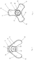
- FIG. 1 and 2 show an anvil 20 according to the invention with a round outer periphery 22. Parallel to this outer circumference 22 is also a round groove 24. This can serve as a counter-positioning means 21 to a positioning means 12 of the frame 11. This will be explained later.
- three recesses 25 are provided on the anvil 20. These serve, as will also be shown in more detail, to easily remove an anvil 20 arranged lower mold 23 from the anvil 20.
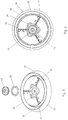
- the 3 and 4 show a punch 30 according to the invention, which was introduced into a frame 11.
- the frame 11 comprises three arms 13, on each of which a positioning means 12 is arranged in the lower region, or serve the lower parts of the arms 13 as a positioning means 12.
- the positioning means 12 can with the from the Fig.1 and 2 known Jacobpositionierstoff 21 in the form of the groove 24 are brought into operative connection.
- FIGS. 5 and 6 It is now shown how a lower mold 23 and a lower part 42 of the rivet element 40 can be arranged on the anvil.
- the lower mold 23 is brought to the anvil 20 for conditioning and then the lower part 42 of the rivet element 40.
- the recesses 25 protrude beyond the outer periphery of the lower mold 23. If an operator grasps with one's finger or a tool into one of the recesses 25, it can engage behind the lower molding tool 23 and simply remove it from the anvil 20.
- FIGS. 7 and 8 show a similar situation for the stamp 30. This is here again in society 11 arranged.
- an upper mold 33 is latched on the punch 30 by means of the two locking elements 32.
- the upper part 41 of the rivet 40 This can either be locked on the upper mold 33 or the punch 30 or just at the desired location on the Surface element 50 are placed to bring by actuation of the punch 30 by means of a force applied to the actuating surface 31, the upper 41 and lower part 42 of the rivet element 40 in operative connection with each other and to rivet on the surface element 50.
- Fig. 9 the entire structure of the tool 10 can be seen. It can be seen that the punch 30 is brought into the frame 11, which in turn can come to rest on the anvil 20. However, the punch 30 is detachable from the frame 11. In its upper part, the punch 30 has the Actuating surface 31. This is in the assembled state also from the 10 and 11 seen. Here you can also see that the arms 13 of the frame 11 come with their positioning means 12 in the formed asellespositionierstoff 21 groove 24 of the anvil 20 to the plant. Between the punch 30 and the anvil 20, a gap is provided, which, however, when actuated by the two parts 41, 42 of the rivet element 40 are filled.
- the punch 30 moves in the frame 11 in the direction of the anvil 22 so that a deformation of the two parts 41, 42 of the rivet element 40 can take place. If upper 33 and lower forming tools 23 are also provided, targeted beading of one or both parts 41, 42 of the rivet element 40 takes place, which leads to riveting of the rivet element 40 on the surface element 50.
- the tool 10 with punch 30, frame 11 and anvil shows 20.
- a surface element 50 and an upper 41 and a lower part 42 of a rivet element 40 shown symbolically.
- the anvil 20 is arranged below the surface element 50, while the stamp 30 with the frame 11 is located on the upper side 51 of the surface element 50.
- the upper part 41 is also arranged on the upper side 51 of the surface element 50, while the lower part 42 is below the surface element 50 near the anvil 20.
Landscapes
- Engineering & Computer Science (AREA)
- Textile Engineering (AREA)
- Insertion Pins And Rivets (AREA)
Description
- Die Erfindung betrifft ein Werkzeug zur Anbringung von Nietelementen auf einem Flächenelement sowie ein Befestigungssystem hierzu. Der Begriff Nietelement ist in diesem Zusammenhang weit auszulegen und umfasst sämtliche Elemente die durch Kaltverformung, Bördeln oder sonstige Nietvorgänge an biegeschlaffen und/oder flexiblen Flächenelementen, wie Bekleidung, Stoffen, Leder, Kunstleder, Kunststoffen, Folien, Taschen, Rucksäcken, Koffern, Portemonnaies etc. befestigbar sind. Hierunter fallen unter Anderem Druckknöpfe, Teile von Druckknöpfen, Ziernieten, Befestigungsnieten, Ösen, Knöpfe und andere Zierelemente.
- Von Personen, die sich mit Hobbyschneiderei, Handarbeiten und anderen kreativen Tätigkeiten beschäftigen oder die einfach Gegenstände, wie Kleidungsstücke, Gürtel oder auch dekorative Elemente verändern oder verzieren wollen, besteht der Bedarf an Handwerkzeugen, um verschiedene Nietelemente, wie Druckknöpfe, Druckknopfteile, Knöpfe, Befestigungsnieten, Ösen, Ziernieten, andere Zierelemente oder Ähnliches an einem Flächenelement aus einem Flächenmaterial, wie Leder, Kunstleder, textilem Material, Kunststoff oder Ähnlichem durch Kaltverformen, insbesondere durch Bördeln, anzubringen.
- Die
US 2,425,586 beschreibt eine Vorrichtung zum Anbringen von Zierelementen, wie Nägeln oder Nieten an einem Flächenelement. Hier können jedoch nur zierende Elemente angebracht werden. Eine Anbringung, wie beispielsweise Druckknöpfe oder Ähnlichem, ist nicht vorgesehen. - Die
US 1,438,692 sowie dieEP 0 050 004 B1 beschreiben jeweils Vorrichtungen zur Anbringung von Ösen. Hier wird mittels eines Werkzeuges, auf welches eine Kraft ausgeübt wird, eine Öse in einem bahnartigen oder flächigen Material, befestigt. Eine Anbringung von Druckknöpfen oder Ähnlichem ist hier jedoch nicht vorgesehen, ebenso wenig eine Anbringung von Ziernieten. - Die Dokumente
US 2,413,702 undUS 2,615,590 beschreiben jeweils Handwerkzeuge zur Anbringung von Druckknöpfen auf flächigen Materialien. Es sind ein oberer und ein unterer Werkzeugteil vorgesehen, welche in Wirkverbindung unter Zwischenschaltung des betreffenden Nietteils miteinander gebracht werden müssen, um den Nietteil auf dem Flächenelement zu befestigen. Hierbei ist es jedoch schwierig, beide Werkzeugteile zueinander zu positionieren und auszurichten, um eine sichere und vollständige korrekte Vernietung zu erzielen. - Das Dokument
US 3,964,660 beschreibt ebenfalls ein Handwerkezug zur Anbringung von Teilen von Druckköpfen. Hier ist es nicht vorgesehen, andere Elemente, wie Zierelemente, anzubringen. Zur Anbringung sind jeweils zwei Arbeitsschritte erforderlich, was für eine Bedienperson umständlich ist. - Das Dokument
EP 0 121 900 B1 beschreibt ebenfalls ein Handwerkzeug zur Anbringung einer Vielzahl von Nietelementen, wie Druckknöpfen, Ösen, Befestigungsnieten, Ziernieten, Knöpfen o.dgl. Bei diesem Handwerkzeug kann jedoch ein betreffender Niet nicht an einer beliebigen Stelle eines Kleidungsstückes angeordnet werden. Vielmehr sind die Werkzeugteile so miteinander verbunden, dass sie nur in der Nähe des Randes des Flächenelementes angeordnet werden können. Darüber hinaus sind auch hier mehrere Arbeitsschritte notwendig, um ein entsprechendes Nietelement zu befestigen. - Aufgabe der Erfindung ist es daher, die zuvor genannten Nachteile der verschiedenen Werkzeuge zu vermeiden und ein neues Werkzeug zu schaffen, welches die unterschiedlichsten Nietelemente auf möglichst einfache Art und Weise an einer beliebigen Stelle in einem Flächenelement befestigen kann. Weiterhin ist es Aufgabe der Erfindung, ein Befestigungssystem vorzusehen, welches unterschiedliche Nietelemente befestigen kann. Diese Aufgaben werden durch die kennzeichnenden Merkmale der Ansprüche eins und neun gelöst, denen folgende besondere Bedeutung zukommt.
- Das erfindungsgemäße Werkzeug besitzt einen Amboss und einen Stempel, wobei der Amboss unterhalb des Flächenelementes und der Stempel an der Oberseite des Flächenelementes anordnenbar ist. Unter Zwischenschaltung des Flächenelementes sowie der Teile des Nietelementes sind Stempel und Amboss in Wirkverbindung bringbar. Hierzu ist am Stempel eine Betätigungsfläche vorgesehen, welche durch Kraftbeaufschlagung, beispielsweise durch einen Hammerschlag oder Ähnliches, den Stempel mit dem Amboss in Wirkverbindung bringen kann. Bei der Erfindung ist nun vorgesehen, dass im Amboss der untere Teil des Nietelementes und/oder am Stempel der obere Teil des Nietelementes angeordnet ist. Amboss und Stempel bilden dabei zwei baulich getrennte oder trennbare Teile, die an einer beliebigen Stelle des Flächenelementes zum Einsatz kommen zu können. Zur Positionierung von Amboss und Stempel zueinander ist der Stempel in ein Gestell einbringbar, welches Positioniermittel aufweist, die mit einem oder mehreren Gegenpositioniermitteln des Ambosses in Wirkverbindung bringbar sind, um Amboss und Stempel zueinander auszurichten. Wenn in dieser Position die Betätigungsfläche des Stempels mit einer Kraft beaufschlagt wird, ist das zwischen Amboss und Stempel befindliche Nietelement am Flächenelement festlegbar. Hierzu ist nur eine einzige Betätigung des Werkzeugs notwendig. Mehrere Betätigungsschritte, wie im Stand der Technik bekannt sind hier nicht notwendig. Je nach Nietelement kann es erforderlich sein, zuerst ein Loch in das Flächenelement einzubringen, bevor das Nietelement angebracht wird. Dies ist mit dem erfindungsgemäßen Werkzeug jedoch auch einfach möglich, indem ein entsprechendes Lochwerkzeug am Amboss bzw. am Stempel vorgesehen und dann das Werkzeug betätigt wird. Durch die vorerwähnten Maßnahmen wird das erfindungsgemäße Werkzeug einfach und komfortabel bedienbar. Es ist sehr einfach, so die beiden Teile des Werkzeuges, nämlich den Amboss und den Stempel zueinander auszurichten und eine einzelne Betätigung durchzuführen, um das Nietelement am Flächenelement festzulegen. Dies ist für eine Bedienperson sehr komfortabel. Des Weiteren ist für den Stempel ein oberes Formwerkzeug und/oder für den Amboss ein unteres Formwerkzeug vorgesehen sind. Diese sind lösbar an dem jeweiligen Werkzeugteil anordbar und an die Form des Nietelementes und/oder an seinen oberen Teil bzw. an seinen unteren Teil angepasst und dienen der Umbördelung des Nietelementes bzw. dessen Teilen bei Betätigung des Werkzeuges. Wenn die Formwerkzeuge lösbar sind, ist es möglich, mit dem gleichen Werkzeug die unterschiedlichsten Größen und Formen von Nietelementen zu verarbeiten. Somit müssen nur die entsprechenden Formwerkzeuge ausgetauscht werden, so dass sie zu dem zu verarbeitenden Nietelement passen, um die verschiedenen Nietelemente zu vernieten. Dies ist für eine Bedienperson besonders einfach, da nur ein Werkzeug für die unterschiedlichsten Formen und Größen von Nietelementen benötigt wird. Die Verwendung von Formwerkzeugen allgemein dient einer korrekten Umbördelung bei der Anbringung der Nietelemente.
- Besonders bevorzugt weist der Amboss einen runden Außenumfang und/oder eine runde Nut auf, welche als Gegenpositioniermittel dienen. Am Gestell sind mehrere, vorzugsweise drei Arme vorgesehen, die als Positioniermittel ausgebildet sind. Die Arme des Gestells können dann mit dem Außenumfang des Ambosses oder auch mit der Nut des Ambosses in Wirkverbindung bringbar sein. Hierbei wird der Außenumfang des Ambosses von den Armen umschlossen bzw. dringen die Arme ein wenig in die entsprechende Nut am Amboss ein. Letzteres ist besonders vorteilhaft, da so das Gestell noch besser am Amboss halterbar ist und nicht verrutschen kann. Eine Anzahl von drei Armen ist deswegen vorteilhaft, weil diese nicht kippen können, unabhängig von der Beschaffenheit der Arbeitsfläche auf der gearbeitet wird und anderen Randbedingungen. Wenn die Arme in die Nut des Ambosses eindringen, ist eine besonders gute Ausrichtung von Amboss und Stempel zueinander gegeben. Aber auch, wenn die Arme den Außenumfang des Ambosses umschließen, sind die Werkzeugteile gut zueinander auszurichten. Wird jetzt der Stempel durch Beaufschlagung der Betätigungsfläche mit einer Kraft betätigt, so wirken Amboss und Stempel optimal aufeinander ein.
- Vorzugsweise ist der Stempel lösbar im Gestell anordnenbar und ist bei Beaufschlagung der Betätigungsfläche mit einer Kraft im Gestell in Richtung des Ambosses bewegbar. Dies ist eine besonders einfache Ausführung von Stempel und Gestell. Darüber hinaus können Stempel und Gestell unabhängig voneinander ausgetauscht werden, falls dies erforderlich ist.
- Besonders bevorzugt sind bei der Verwendung eines oberen lösbaren Formwerkzeuges am Stempel und/oder am Formwerkzeug selbst ein oder mehrere Rastelemente vorgesehen. Durch diese Rastelemente ist das obere Formwerkzeug am Stempel verrastbar oder verklemmbar. So kann das obere Formwerkzeug am Stempel verrastet und mit diesem bei der Betätigung des Werkezuges mitbewegt werden.
- Des Weiteren weist der Amboss vorzugsweise eine oder mehrere Ausnehmungen auf, die bei am Amboss angeordnetem unterem Formwerkzeug von diesem bereichsweise verdeckt werden. Soll das untere Formwerkzeug vom Amboss entfernt werden, kann es dann mithilfe der Ausnehmungen von einer Bedienperson von Hand oder mit einem Werkzeug hintergriffen werden, um das untere Formwerkzeug einfach aus dem Amboss zu entfernen.
- In einem weiteren bevorzugten Ausführungsbeispiel ist am Stempel und/oder am Amboss und/oder am Gestell wenigstens eine Skala vorgesehen. Diese Skala kann dazu dienen, mehrere Nietelemente in gleichem Abstand zueinander anzubringen, beispielsweise zur Bildung einer Knopf- oder Druckknopfleiste oder auch bei der Anbringung mehrerer Zier- oder Befestigungsnieten in einer Reihe. Die Skala hilft dann bei der Positionierung der unterschiedlichen Nietelemente zueinander, da auf diese Art und Weise die Entfernung auf dem Flächenelement einfach abzulesen ist.
- Vorzugsweise bestehen der Stempel und/oder der Amboss und/oder das Gestell ganz oder teilweise aus einem Kunststoff. So sind die einzelnen Teile einfach herstellbar und das Werkzeug kann ein geringes Gewicht aufweisen.
- Weiterhin umfasst die Erfindung ein Befestigungssystem für Nietelemente an einem Flächenelement, welches wenigstens eines der zuvor beschriebenen Werkzeuge umfasst sowie mehrere Sets von oberen und unteren Formwerkzeugen. Ein derartiges Befestigungssystem kann der Befestigung von Nietelementen von unterschiedlichen Formen und Größen dienen. So muss eine Bedienperson lediglich im Besitz eines Befestigungssystems sein, um Anwendungen von Nietelementen an den verschiedensten Flächenelementen aus unterschiedlichen Materialien zu befestigen.
- Weitere Vorteile und Ausführungsbeispiele ergeben sich aus der nachfolgenden Beschreibung, den Unteransprüchen sowie den Zeichnungen. In den Zeichnungen ist das Werkzeug in einem Ausführungsbeispiel dargestellt. Es zeigen:
- Fig. 1:
- einen erfindungsgemäßen Amboss perspektivisch,
- Fig. 2:
- den Amboss aus
Fig. 1 in Draufsicht, - Fig. 3:
- ein erfindungsgemäßes Gestell mit Stempel perspektivisch,
- Fig. 4:
- Stempel und Gestell aus
Fig. 3 in Ansicht von unten, - Fig. 5:
- eine perspektivische Explosionsdarstellung von Amboss, Formwerkzeug und unterem Teil des Nietelementes,
- Fig. 6:
- die Bauteile aus
Fig. 5 in Draufsicht, - Fig. 7:
- eine perspektivische Explosionsdarstellung von Stempel, Gestell, oberem Formwerkzeug und oberem Teil des Nietelementes,
- Fig. 8:
- die Bauteile aus
Fig. 7 in Ansicht von unten, - Fig. 9:
- Stempel, Gestell und Amboss in Explosionsdarstellung in Seitenansicht,
- Fig. 10:
- Amboss, Gestell und Stempel zusammengebaut perspektivisch,
- Fig. 11:
- die Bauteile aus
Fig. 10 in Seitenansicht, - Fig. 12:
- das Werkzeug mit Teilen des Nietelements und Flächenelement in Seitenansicht.
- Die
Fig. 1 und 2 zeigen einen erfindungsgemäßen Amboss 20 mit einem runden Außenumfang 22. Parallel zu diesem Außenumfang 22 verläuft eine ebenfalls runde Nut 24. Diese kann als Gegenpositioniermittel 21 zu einem Positioniermittel 12 des Gestells 11 dienen. Dies wird später noch näher erklärt werden. - Darüber hinaus sind am Amboss 20 drei Ausnehmungen 25 vorgesehen. Diese dienen, wie ebenfalls noch näher gezeigt werden wird, dazu, ein am Amboss 20 angeordnetes unteres Formwerkzeug 23 vom Amboss 20 problemlos zu entfernen.
- Des Weiteren sind drei Skalen 26 am Amboss 20 vorgesehen. Mit Hilfe dieser Skalen 26 können mehrere Nietelemente 40 in einem definierten Abstand zueinander an einem Flächenelement 50 angeordnet werden. Die Skalen 26 helfen dabei, die betreffenden Abstände zwischen den Nietelementen 40 auszumessen und die Nietelemente 40 korrekt zu positionieren.
DieFig. 3 und 4 zeigen einen erfindungsgemäßen Stempel 30, der in ein Gestell 11 eingebracht wurde. Das Gestell 11 umfasst drei Arme 13, an denen je ein Positioniermittel 12 im unteren Bereich angeordnet ist, bzw. dienen die unteren Teile der Arme 13 als Positioniermittel 12. Die Positioniermittel 12 können mit dem aus denFig.1 und 2 bekannten Gegenpositioniermittel 21 in Form der Nut 24 in Wirkverbindung gebracht werden. Durch die Verwendung von drei Armen 13 mit je einem Positioniermittel 12 ist sichergestellt, dass das Gestell 11 immer sicher auf dem Amboss 20 steht und nicht wackelt. - Im unteren Bereich des Stempels 30 erkennt man noch die beiden Rastelemente 32. Diese dienen dazu, ein oberes Formwerkzeug 33, welches später noch gezeigt werden wird, am Stempel 30 zu verrasten, so dass sich das obere Formwerkzeug 33 mit dem Stempel 30 mit bewegt.
- In den
Fig. 5 und 6 ist nun gezeigt, wie ein unteres Formwerkzeug 23 und ein unterer Teil 42 des Nietelementes 40 am Amboss angeordnet werden können. Hierzu wird zunächst das untere Formwerkzeug 23 am Amboss 20 zur Anlage gebracht und danach der untere Teil 42 des Nietelementes 40. Wie insbesondere ausFig. 6 erkennbar ist, ragen die Ausnehmungen 25 über den Außenumfang des unteren Formwerkzeuges 23 heraus. Greift eine Bedienperson mit dem Finger oder einem Werkzeug in eine der Ausnehmungen 25 hinein, so kann sie das untere Formwerkzeug 23 hintergreifen und einfach vom Amboss 20 entfernen. - Die
Fig. 7 und 8 zeigen eine ähnliche Situation für den Stempel 30. Dieser ist hier wieder im Gesell 11 angeordnet. Zunächst wird ein oberes Formwerkzeug 33 am Stempel 30 verrastet mit Hilfe der beiden Rastelemente 32. Danach kommt der obere Teil 41 des Nietelementes 40. Dieser kann entweder auch am oberen Formwerkzeug 33 oder am Stempel 30 verrastet werden oder einfach nur an der gewünschten Stelle auf das Flächenelement 50 gelegt werden, um durch eine Betätigung des Stempels 30 mittels einer Kraftbeaufschlagung der Betätigungsfläche 31 den oberen 41 und unteren Teil 42 des Nietelementes 40 miteinander in Wirkverbindung zu bringen und am Flächenelement 50 zu vernieten. - Aus
Fig. 9 ist der gesamte Aufbau des Werkzeuges 10 erkennbar. Man sieht, dass der Stempel 30 in das Gestell 11 hineingebracht wird, welches wiederum auf dem Amboss 20 zur Anlage kommen kann. Der Stempel 30 ist jedoch vom Gestell 11 lösbar. In seinem oberen Bereich weist der Stempel 30 die Betätigungsfläche 31 auf. Dies ist im zusammengebauten Zustand auch aus denFig. 10 und 11 ersichtlich. Hier erkennt man auch, dass die Arme 13 des Gestells 11 mit ihren Positioniermitteln 12 in der als Gegenpositioniermittel 21 ausgebildeten Nut 24 des Ambosses 20 zur Anlage kommen. Zwischen dem Stempel 30 und dem Amboss 20 ist eine Lücke vorgesehen, welche jedoch bei Betätigung von den beiden Teilen 41, 42 des Nietelementes 40 ausgefüllt werden. Wird nun die Betätigungsfläche 31 mit einer Kraft beaufschlagt, so bewegt sich der Stempel 30 im Gestell 11 in Richtung des Ambosses 22, sodass eine Verformung der beiden Teile 41, 42 des Nietelementes 40 erfolgen kann. Sind noch obere 33 und untere Formwerkzeuge 23 vorgesehen, so findet eine gezielte Umbördelung eines oder beider Teile 41, 42 des Nietelementes 40 statt, was zur Vernietung des Nietelementes 40 am Flächenelement 50 führt. -
Fig. 12 schließlich zeigt das Werkzeug 10 mit Stempel 30, Gestell 11 und Amboss 20. Es sind jedoch auch ein Flächenelement 50 sowie ein oberer 41 und ein unterer Teil 42 eines Nietelements 40 symbolisch dargestellt. Man erkennt, dass der Amboss 20 unterhalb des Flächenelementes 50 angeordnet ist, während der Stempel 30 mit Gestell 11 sich auf der Oberseite 51 des Flächenelementes 50 befindet. Bei der symbolischen Darstellung der beiden Teile 41, 42 des Nietelements 40 ist der obere Teil 41 ebenfalls auf der Oberseite 51 des Flächenelementes 50 angeordnet, während sich der untere Teil 42 unter dem Flächenelement 50 nahe des Ambosses 20 befindet. Bei einer Beaufschlagung der Betätigungsfläche 31 mit einer Kraft findet dann eine Kaltverformung eines oder beider Teile 41, 42 statt, um das Nietelement 40 herzustellen. - Abschließend sei noch darauf hingewiesen, dass die hier dargestellten Ausführungsformen lediglich beispielhafte Verwirklichungen der Erfindung sind. Diese ist nicht darauf beschränkt. Es sind vielmehr noch Abänderungen und Abwandlungen möglich. So ist es beispielsweise denkbar, dass das Gestell mehr oder weniger Arme aufweist. Außerdem können auch die Positioniermittel und Gegenpositioniermittel anders ausgebildet sein.
-
- 10
- Werkzeug
- 11
- Gestell
- 12
- Positioniermittel
- 13
- Arm
- 20
- Amboss
- 21
- Gegenpositioniermittel
- 22
- Außenumfang von 20
- 23
- Unteres Formwerkzeug
- 24
- Nut
- 25
- Ausnehmung
- 26
- Skala
- 30
- Stempel
- 31
- Betätigungsfläche
- 32
- Rastelement
- 33
- Oberes Formwerkzeug
- 40
- Nietelement
- 41
- Oberer Teil von 40
- 42
- Unterer Teil von 40
- 50
- Flächenelement
- 51
- Oberseite von 50
Claims (7)
- Werkzeug (10) zur Anbringung von Nietelementen (40) wie Druckknöpfen, Druckknopfteilen, Ösen, Ziernieten, Befestigungsnieten, Knöpfen o.ä. an einem Flächenelement (50) aus einem biegeschlaffen und/oder flexiblen, flächigen Material wie textilem Material, Leder, Kunstleder, Kunststoff o.ä., durch Kaltverformen,
wobei ein Amboss (20) vorgesehen ist, welcher unterhalb des Flächenelementes (50) angeordnet werden kann,
wobei weiterhin ein Stempel (30) vorgesehen ist, welcher oberhalb der Oberseite (51) des Flächenelements (50) anordnenbar ist und welcher unter Zwischenschaltung des Flächenelements (50) mit dem Amboss (20) in Wirkverbindung bringbar ist,
wobei am Stempel (30) eine Betätigungsfläche (31) vorgesehen ist, welche durch Kraftbeaufschlagung den Stempel (30) mit dem Amboss (20) in Wirkverbindung bringen kann,
wobei in den Amboss (20) der untere Teil (42) des Nietelements (40) und in oder an dem Stempel (30) der obere Teil (41) des Nietelements (40) anordnenbar ist
und wobei der Amboss (20) und der Stempel (30) zwei baulich getrennte oder trennbare Teile darstellen
dadurch gekennzeichnet,
dass der Stempel (30) in ein Gestell (11) einbringbar ist, welches Positioniermittel (12) aufweist, die mit einem oder mehreren Gegenpositioniermitteln (21) des Ambosses (20) in Wirkverbindung bringbar sind, um den Amboss (20) und den Stempel (30) zueinander auszurichten,
und dass bei Positionierung von Amboss (20) und Stempel (30) zueinander das Nietelement (40) durch Beaufschlagung der Betätigungsfläche (31) mit einer Kraft am Flächenelement (50) festlegbar ist
dass für den Stempel (30) ein oberes Formwerkzeug (33) und/oder für den Amboss (20) ein unteres Formwerkzeug (23) vorgesehen sind, welche lösbar und an die Form des Nietelementes (40) und/oder an seinen oberen Teil (41) und/oder an seinen unteren Teil (42) angepasst sind und der Kaltverformung des Nietelementes (40) bzw. dessen Teilen (41, 42) bei Betätigung des Werkzeugs (10) dienen
dass ein oder mehrere Rastelemente (32) oder Ausnehmungen (25) vorgesehen sind, durch welche das obere Formwerkzeug (33) am Stempel (30) und/oder das untere Formwerkzeug am Amboss (20) lösbar befestigbar ist. - Werkzeug (10) nach Anspruch 1, dadurch gekennzeichnet, dass der Amboss (20) einen im Wesentlichen runden Außenumfang (22) aufweist und/oder eine im Wesentlichen runde Nut (24), welche als Gegenpositioniermittel (21) dienen, während das Gestell (11) mehrere, insbesondere drei, Arme (13) besitzt, die als Positioniermittel (12) ausgebildet sind und den Außenumfang (22) des Ambosses (20) umschließen können oder in die Nut (24) des Ambosses (20) zumindest bereichsweise einbringbar sind.
- Werkzeug (10) nach einem der Ansprüche 1 oder 2, dadurch gekennzeichnet, dass der Stempel (30) lösbar im Gestell (11) anordnenbar ist
und dass der Stempel (30) sich im Gestell (11) in Richtung des Ambosses (20) bewegt, wenn die Betätigungsfläche (31) mit einer Kraft beaufschlagt wird. - Werkzeug (10) nach einem der Ansprüche 1 bis 3, dadurch gekennzeichnet, dass der Amboss (20) eine oder mehrere Ausnehmungen (25) aufweist, die bei am Amboss (20) angeordnetem unterem Formwerkzeug (23) von dem unteren Formwerkzeug (23) bereichsweise verdeckt werden und die von einer Person oder einem Werkzeug hintergriffen werden können, um das untere Formwerkzeug (23) vom Amboss (20) zu entfernen.
- Werkzeug (10) nach einem der Ansprüche 1 bis 4, dadurch gekennzeichnet, dass am Stempel (30) und/oder am Amboss (20) und/oder am Gestell (11) wenigstens eine Skala (26) vorgesehen ist.
- Werkzeug (10) nach einem der Ansprüche 1 bis 5, dadurch gekennzeichnet, dass der Stempel (30) und/oder der Amboss (20) und/oder das Gestell (11) ganz oder teilweise aus Kunststoff bestehen.
- Befestigungssystem für Nietelemente (40) wie Druckknöpfe, Druckknopfteile, Ösen, Ziernieten, Befestigungsnieten, Knöpfe o.ä. an einem Flächenelement (50) umfassend wenigstens ein Werkzeug (10) nach einem der Ansprüche 1 bis 6 und mehrere Sets von oberen (41) und unteren Formwerkzeugen (42).
Applications Claiming Priority (1)
| Application Number | Priority Date | Filing Date | Title |
|---|---|---|---|
| DE201310109812 DE102013109812B3 (de) | 2013-09-09 | 2013-09-09 | Werkzeug zur Anbringung von Nietelementen an einem Flächenelement und Befestigungssystem hierzu |
Publications (2)
| Publication Number | Publication Date |
|---|---|
| EP2853167A1 EP2853167A1 (de) | 2015-04-01 |
| EP2853167B1 true EP2853167B1 (de) | 2016-04-13 |
Family
ID=51301137
Family Applications (1)
| Application Number | Title | Priority Date | Filing Date |
|---|---|---|---|
| EP14180319.7A Active EP2853167B1 (de) | 2013-09-09 | 2014-08-08 | Werkzeug zur Anbringung von Nietelementen an einem Flächenelement und Befestigungssystem hierzu |
Country Status (2)
| Country | Link |
|---|---|
| EP (1) | EP2853167B1 (de) |
| DE (1) | DE102013109812B3 (de) |
Families Citing this family (1)
| Publication number | Priority date | Publication date | Assignee | Title |
|---|---|---|---|---|
| DE102017108311A1 (de) * | 2017-04-19 | 2018-10-25 | DAST GmbH & Co. KG | Montageschutz |
Family Cites Families (8)
| Publication number | Priority date | Publication date | Assignee | Title |
|---|---|---|---|---|
| US1438692A (en) * | 1921-02-16 | 1922-12-12 | G W J Murphy Company | Tool for setting fastener parts |
| US2413702A (en) * | 1945-05-29 | 1947-01-07 | Scovill Manufacturing Co | Hand tool for setting snap fasteners |
| US2425586A (en) * | 1946-07-13 | 1947-08-12 | Wolff George | Spot setting device |
| US2615590A (en) * | 1950-01-12 | 1952-10-28 | John Dritz & Sons | Snap fastener assembly tool with penetrable sleeve |
| US3964660A (en) * | 1975-03-13 | 1976-06-22 | Hensley Donald W | Snap attaching tool |
| JPS588455Y2 (ja) * | 1980-10-09 | 1983-02-15 | ワイケイケイ株式会社 | 鳩目取付治具 |
| DE8310656U1 (de) * | 1983-04-12 | 1983-09-29 | William Prym-Werke Kg, 5190 Stolberg | Schlagwerkzeugkombination |
| WO2010076347A1 (es) * | 2008-12-31 | 2010-07-08 | Plasticos Alco, S.L. | Máquina para colocación de ojales |
-
2013
- 2013-09-09 DE DE201310109812 patent/DE102013109812B3/de not_active Withdrawn - After Issue
-
2014
- 2014-08-08 EP EP14180319.7A patent/EP2853167B1/de active Active
Also Published As
| Publication number | Publication date |
|---|---|
| EP2853167A1 (de) | 2015-04-01 |
| DE102013109812B3 (de) | 2014-12-11 |
Similar Documents
| Publication | Publication Date | Title |
|---|---|---|
| DE102012001490B4 (de) | Schneidwerkzeug | |
| DE69013005T2 (de) | Spielzeug mit zugänglichem innenraum. | |
| DE2460643A1 (de) | Wiederverwendbarer sicherheitsanhaenger und entriegelungswerkzeug fuer denselben | |
| EP3328232A1 (de) | Gepäckstück mit stoppereinrichtung | |
| DE102019119267B4 (de) | Schnallenanordnung mit einklemmschutz | |
| DE102012109008A1 (de) | Formveränderungs-Positioniervorrichtung für einen Werkzeuggriff | |
| DE102013109812B3 (de) | Werkzeug zur Anbringung von Nietelementen an einem Flächenelement und Befestigungssystem hierzu | |
| EP3968810B1 (de) | Zaum-stirnband | |
| AT515844B1 (de) | Emblemträger | |
| EP0121900B1 (de) | Schlagwerkzeugkombination | |
| DE2228463C3 (de) | Zange zum Ansetzen von Druckknöpfen u.dgl | |
| EP3047749B1 (de) | Zierband | |
| EP0003296A1 (de) | Betätigungshilfsmittel für einen Reissverschluss | |
| DE289518C (de) | ||
| DE429255C (de) | Auswechselbarer Absatzfleck | |
| DE202012008356U1 (de) | Schutzelement für ein Druckknopf-Innenelement | |
| WO2020001724A1 (de) | Sichtelement | |
| DE465343C (de) | Presse zur Befestigung von Druckknopfteilen an Handschuhen, Gamaschen u. dgl. | |
| DE20316855U1 (de) | Fußmatten- und Lederwarenabzeichen | |
| DE102010038243B4 (de) | Halteeinheit | |
| EP1961327B1 (de) | Kofferschild | |
| DE102004009727B4 (de) | Schlüsselring | |
| DE202015005453U1 (de) | Gepäckstück | |
| DE202020101626U1 (de) | Schutzbekleidung | |
| DE20212183U1 (de) | Zweiteiliger Kabelbinder |
Legal Events
| Date | Code | Title | Description |
|---|---|---|---|
| PUAI | Public reference made under article 153(3) epc to a published international application that has entered the european phase |
Free format text: ORIGINAL CODE: 0009012 |
|
| 17P | Request for examination filed |
Effective date: 20140808 |
|
| AK | Designated contracting states |
Kind code of ref document: A1 Designated state(s): AL AT BE BG CH CY CZ DE DK EE ES FI FR GB GR HR HU IE IS IT LI LT LU LV MC MK MT NL NO PL PT RO RS SE SI SK SM TR |
|
| AX | Request for extension of the european patent |
Extension state: BA ME |
|
| R17P | Request for examination filed (corrected) |
Effective date: 20150326 |
|
| RBV | Designated contracting states (corrected) |
Designated state(s): AL AT BE BG CH CY CZ DE DK EE ES FI FR GB GR HR HU IE IS IT LI LT LU LV MC MK MT NL NO PL PT RO RS SE SI SK SM TR |
|
| GRAP | Despatch of communication of intention to grant a patent |
Free format text: ORIGINAL CODE: EPIDOSNIGR1 |
|
| RIC1 | Information provided on ipc code assigned before grant |
Ipc: A41H 37/00 20060101AFI20151021BHEP Ipc: A41H 37/04 20060101ALI20151021BHEP |
|
| INTG | Intention to grant announced |
Effective date: 20151112 |
|
| GRAS | Grant fee paid |
Free format text: ORIGINAL CODE: EPIDOSNIGR3 |
|
| GRAA | (expected) grant |
Free format text: ORIGINAL CODE: 0009210 |
|
| AK | Designated contracting states |
Kind code of ref document: B1 Designated state(s): AL AT BE BG CH CY CZ DE DK EE ES FI FR GB GR HR HU IE IS IT LI LT LU LV MC MK MT NL NO PL PT RO RS SE SI SK SM TR |
|
| REG | Reference to a national code |
Ref country code: GB Ref legal event code: FG4D Free format text: NOT ENGLISH |
|
| REG | Reference to a national code |
Ref country code: AT Ref legal event code: REF Ref document number: 789093 Country of ref document: AT Kind code of ref document: T Effective date: 20160415 Ref country code: CH Ref legal event code: EP Ref country code: CH Ref legal event code: NV Representative=s name: ISLER AND PEDRAZZINI AG, CH |
|
| REG | Reference to a national code |
Ref country code: IE Ref legal event code: FG4D Free format text: LANGUAGE OF EP DOCUMENT: GERMAN |
|
| REG | Reference to a national code |
Ref country code: DE Ref legal event code: R096 Ref document number: 502014000609 Country of ref document: DE |
|
| REG | Reference to a national code |
Ref country code: NL Ref legal event code: FP |
|
| REG | Reference to a national code |
Ref country code: LT Ref legal event code: MG4D |
|
| REG | Reference to a national code |
Ref country code: FR Ref legal event code: PLFP Year of fee payment: 3 |
|
| PG25 | Lapsed in a contracting state [announced via postgrant information from national office to epo] |
Ref country code: LT Free format text: LAPSE BECAUSE OF FAILURE TO SUBMIT A TRANSLATION OF THE DESCRIPTION OR TO PAY THE FEE WITHIN THE PRESCRIBED TIME-LIMIT Effective date: 20160413 Ref country code: PL Free format text: LAPSE BECAUSE OF FAILURE TO SUBMIT A TRANSLATION OF THE DESCRIPTION OR TO PAY THE FEE WITHIN THE PRESCRIBED TIME-LIMIT Effective date: 20160413 Ref country code: FI Free format text: LAPSE BECAUSE OF FAILURE TO SUBMIT A TRANSLATION OF THE DESCRIPTION OR TO PAY THE FEE WITHIN THE PRESCRIBED TIME-LIMIT Effective date: 20160413 Ref country code: NO Free format text: LAPSE BECAUSE OF FAILURE TO SUBMIT A TRANSLATION OF THE DESCRIPTION OR TO PAY THE FEE WITHIN THE PRESCRIBED TIME-LIMIT Effective date: 20160713 |
|
| PG25 | Lapsed in a contracting state [announced via postgrant information from national office to epo] |
Ref country code: PT Free format text: LAPSE BECAUSE OF FAILURE TO SUBMIT A TRANSLATION OF THE DESCRIPTION OR TO PAY THE FEE WITHIN THE PRESCRIBED TIME-LIMIT Effective date: 20160816 Ref country code: SE Free format text: LAPSE BECAUSE OF FAILURE TO SUBMIT A TRANSLATION OF THE DESCRIPTION OR TO PAY THE FEE WITHIN THE PRESCRIBED TIME-LIMIT Effective date: 20160413 Ref country code: RS Free format text: LAPSE BECAUSE OF FAILURE TO SUBMIT A TRANSLATION OF THE DESCRIPTION OR TO PAY THE FEE WITHIN THE PRESCRIBED TIME-LIMIT Effective date: 20160413 Ref country code: ES Free format text: LAPSE BECAUSE OF FAILURE TO SUBMIT A TRANSLATION OF THE DESCRIPTION OR TO PAY THE FEE WITHIN THE PRESCRIBED TIME-LIMIT Effective date: 20160413 Ref country code: LV Free format text: LAPSE BECAUSE OF FAILURE TO SUBMIT A TRANSLATION OF THE DESCRIPTION OR TO PAY THE FEE WITHIN THE PRESCRIBED TIME-LIMIT Effective date: 20160413 Ref country code: HR Free format text: LAPSE BECAUSE OF FAILURE TO SUBMIT A TRANSLATION OF THE DESCRIPTION OR TO PAY THE FEE WITHIN THE PRESCRIBED TIME-LIMIT Effective date: 20160413 Ref country code: GR Free format text: LAPSE BECAUSE OF FAILURE TO SUBMIT A TRANSLATION OF THE DESCRIPTION OR TO PAY THE FEE WITHIN THE PRESCRIBED TIME-LIMIT Effective date: 20160714 |
|
| REG | Reference to a national code |
Ref country code: DE Ref legal event code: R097 Ref document number: 502014000609 Country of ref document: DE |
|
| PG25 | Lapsed in a contracting state [announced via postgrant information from national office to epo] |
Ref country code: DK Free format text: LAPSE BECAUSE OF FAILURE TO SUBMIT A TRANSLATION OF THE DESCRIPTION OR TO PAY THE FEE WITHIN THE PRESCRIBED TIME-LIMIT Effective date: 20160413 Ref country code: EE Free format text: LAPSE BECAUSE OF FAILURE TO SUBMIT A TRANSLATION OF THE DESCRIPTION OR TO PAY THE FEE WITHIN THE PRESCRIBED TIME-LIMIT Effective date: 20160413 Ref country code: CZ Free format text: LAPSE BECAUSE OF FAILURE TO SUBMIT A TRANSLATION OF THE DESCRIPTION OR TO PAY THE FEE WITHIN THE PRESCRIBED TIME-LIMIT Effective date: 20160413 Ref country code: SK Free format text: LAPSE BECAUSE OF FAILURE TO SUBMIT A TRANSLATION OF THE DESCRIPTION OR TO PAY THE FEE WITHIN THE PRESCRIBED TIME-LIMIT Effective date: 20160413 Ref country code: RO Free format text: LAPSE BECAUSE OF FAILURE TO SUBMIT A TRANSLATION OF THE DESCRIPTION OR TO PAY THE FEE WITHIN THE PRESCRIBED TIME-LIMIT Effective date: 20160413 |
|
| PLBE | No opposition filed within time limit |
Free format text: ORIGINAL CODE: 0009261 |
|
| STAA | Information on the status of an ep patent application or granted ep patent |
Free format text: STATUS: NO OPPOSITION FILED WITHIN TIME LIMIT |
|
| PG25 | Lapsed in a contracting state [announced via postgrant information from national office to epo] |
Ref country code: SM Free format text: LAPSE BECAUSE OF FAILURE TO SUBMIT A TRANSLATION OF THE DESCRIPTION OR TO PAY THE FEE WITHIN THE PRESCRIBED TIME-LIMIT Effective date: 20160413 |
|
| 26N | No opposition filed |
Effective date: 20170116 |
|
| PG25 | Lapsed in a contracting state [announced via postgrant information from national office to epo] |
Ref country code: MC Free format text: LAPSE BECAUSE OF FAILURE TO SUBMIT A TRANSLATION OF THE DESCRIPTION OR TO PAY THE FEE WITHIN THE PRESCRIBED TIME-LIMIT Effective date: 20160413 |
|
| PG25 | Lapsed in a contracting state [announced via postgrant information from national office to epo] |
Ref country code: SI Free format text: LAPSE BECAUSE OF FAILURE TO SUBMIT A TRANSLATION OF THE DESCRIPTION OR TO PAY THE FEE WITHIN THE PRESCRIBED TIME-LIMIT Effective date: 20160413 |
|
| REG | Reference to a national code |
Ref country code: IE Ref legal event code: MM4A |
|
| PG25 | Lapsed in a contracting state [announced via postgrant information from national office to epo] |
Ref country code: IE Free format text: LAPSE BECAUSE OF NON-PAYMENT OF DUE FEES Effective date: 20160808 |
|
| REG | Reference to a national code |
Ref country code: FR Ref legal event code: PLFP Year of fee payment: 4 |
|
| PG25 | Lapsed in a contracting state [announced via postgrant information from national office to epo] |
Ref country code: LU Free format text: LAPSE BECAUSE OF NON-PAYMENT OF DUE FEES Effective date: 20160808 |
|
| PG25 | Lapsed in a contracting state [announced via postgrant information from national office to epo] |
Ref country code: HU Free format text: LAPSE BECAUSE OF FAILURE TO SUBMIT A TRANSLATION OF THE DESCRIPTION OR TO PAY THE FEE WITHIN THE PRESCRIBED TIME-LIMIT; INVALID AB INITIO Effective date: 20140808 |
|
| PG25 | Lapsed in a contracting state [announced via postgrant information from national office to epo] |
Ref country code: MT Free format text: LAPSE BECAUSE OF FAILURE TO SUBMIT A TRANSLATION OF THE DESCRIPTION OR TO PAY THE FEE WITHIN THE PRESCRIBED TIME-LIMIT Effective date: 20160413 Ref country code: CY Free format text: LAPSE BECAUSE OF FAILURE TO SUBMIT A TRANSLATION OF THE DESCRIPTION OR TO PAY THE FEE WITHIN THE PRESCRIBED TIME-LIMIT Effective date: 20160413 Ref country code: IS Free format text: LAPSE BECAUSE OF FAILURE TO SUBMIT A TRANSLATION OF THE DESCRIPTION OR TO PAY THE FEE WITHIN THE PRESCRIBED TIME-LIMIT Effective date: 20160413 Ref country code: MK Free format text: LAPSE BECAUSE OF FAILURE TO SUBMIT A TRANSLATION OF THE DESCRIPTION OR TO PAY THE FEE WITHIN THE PRESCRIBED TIME-LIMIT Effective date: 20160413 |
|
| PG25 | Lapsed in a contracting state [announced via postgrant information from national office to epo] |
Ref country code: BG Free format text: LAPSE BECAUSE OF FAILURE TO SUBMIT A TRANSLATION OF THE DESCRIPTION OR TO PAY THE FEE WITHIN THE PRESCRIBED TIME-LIMIT Effective date: 20160413 |
|
| PG25 | Lapsed in a contracting state [announced via postgrant information from national office to epo] |
Ref country code: AL Free format text: LAPSE BECAUSE OF FAILURE TO SUBMIT A TRANSLATION OF THE DESCRIPTION OR TO PAY THE FEE WITHIN THE PRESCRIBED TIME-LIMIT Effective date: 20160413 Ref country code: TR Free format text: LAPSE BECAUSE OF FAILURE TO SUBMIT A TRANSLATION OF THE DESCRIPTION OR TO PAY THE FEE WITHIN THE PRESCRIBED TIME-LIMIT Effective date: 20160413 |
|
| PGFP | Annual fee paid to national office [announced via postgrant information from national office to epo] |
Ref country code: BE Payment date: 20180821 Year of fee payment: 5 |
|
| PGFP | Annual fee paid to national office [announced via postgrant information from national office to epo] |
Ref country code: NL Payment date: 20190807 Year of fee payment: 6 |
|
| PGFP | Annual fee paid to national office [announced via postgrant information from national office to epo] |
Ref country code: IT Payment date: 20190830 Year of fee payment: 6 |
|
| PGFP | Annual fee paid to national office [announced via postgrant information from national office to epo] |
Ref country code: CH Payment date: 20190806 Year of fee payment: 6 |
|
| REG | Reference to a national code |
Ref country code: BE Ref legal event code: MM Effective date: 20190831 |
|
| PG25 | Lapsed in a contracting state [announced via postgrant information from national office to epo] |
Ref country code: BE Free format text: LAPSE BECAUSE OF NON-PAYMENT OF DUE FEES Effective date: 20190831 |
|
| REG | Reference to a national code |
Ref country code: AT Ref legal event code: MM01 Ref document number: 789093 Country of ref document: AT Kind code of ref document: T Effective date: 20190808 |
|
| PG25 | Lapsed in a contracting state [announced via postgrant information from national office to epo] |
Ref country code: AT Free format text: LAPSE BECAUSE OF NON-PAYMENT OF DUE FEES Effective date: 20190808 |
|
| REG | Reference to a national code |
Ref country code: CH Ref legal event code: PL |
|
| REG | Reference to a national code |
Ref country code: NL Ref legal event code: MM Effective date: 20200901 |
|
| PG25 | Lapsed in a contracting state [announced via postgrant information from national office to epo] |
Ref country code: CH Free format text: LAPSE BECAUSE OF NON-PAYMENT OF DUE FEES Effective date: 20200831 Ref country code: LI Free format text: LAPSE BECAUSE OF NON-PAYMENT OF DUE FEES Effective date: 20200831 |
|
| PG25 | Lapsed in a contracting state [announced via postgrant information from national office to epo] |
Ref country code: IT Free format text: LAPSE BECAUSE OF NON-PAYMENT OF DUE FEES Effective date: 20200808 |
|
| PG25 | Lapsed in a contracting state [announced via postgrant information from national office to epo] |
Ref country code: NL Free format text: LAPSE BECAUSE OF NON-PAYMENT OF DUE FEES Effective date: 20200901 |
|
| P01 | Opt-out of the competence of the unified patent court (upc) registered |
Effective date: 20230530 |
|
| PGFP | Annual fee paid to national office [announced via postgrant information from national office to epo] |
Ref country code: DE Payment date: 20250704 Year of fee payment: 12 |
|
| PGFP | Annual fee paid to national office [announced via postgrant information from national office to epo] |
Ref country code: GB Payment date: 20250701 Year of fee payment: 12 |
|
| PGFP | Annual fee paid to national office [announced via postgrant information from national office to epo] |
Ref country code: FR Payment date: 20250701 Year of fee payment: 12 |