EP2846124B1 - Geschoss - Google Patents
Geschoss Download PDFInfo
- Publication number
- EP2846124B1 EP2846124B1 EP14002970.3A EP14002970A EP2846124B1 EP 2846124 B1 EP2846124 B1 EP 2846124B1 EP 14002970 A EP14002970 A EP 14002970A EP 2846124 B1 EP2846124 B1 EP 2846124B1
- Authority
- EP
- European Patent Office
- Prior art keywords
- projectile
- ring
- tip
- stop
- external thread
- Prior art date
- Legal status (The legal status is an assumption and is not a legal conclusion. Google has not performed a legal analysis and makes no representation as to the accuracy of the status listed.)
- Active
Links
- 238000013022 venting Methods 0.000 claims description 17
- 239000002360 explosive Substances 0.000 claims description 15
- 238000010008 shearing Methods 0.000 claims description 8
- 230000001747 exhibiting effect Effects 0.000 claims description 2
- 238000000926 separation method Methods 0.000 description 4
- 238000009423 ventilation Methods 0.000 description 4
- 230000015572 biosynthetic process Effects 0.000 description 2
- 238000006243 chemical reaction Methods 0.000 description 2
- 238000010276 construction Methods 0.000 description 2
- 230000014759 maintenance of location Effects 0.000 description 2
- 238000010943 off-gassing Methods 0.000 description 2
- 239000000969 carrier Substances 0.000 description 1
- 230000008878 coupling Effects 0.000 description 1
- 238000010168 coupling process Methods 0.000 description 1
- 238000005859 coupling reaction Methods 0.000 description 1
- 230000001419 dependent effect Effects 0.000 description 1
- 238000010586 diagram Methods 0.000 description 1
- 238000006073 displacement reaction Methods 0.000 description 1
- 230000000694 effects Effects 0.000 description 1
- 238000005516 engineering process Methods 0.000 description 1
- 238000004880 explosion Methods 0.000 description 1
- 239000000383 hazardous chemical Substances 0.000 description 1
- 230000010354 integration Effects 0.000 description 1
- 238000004519 manufacturing process Methods 0.000 description 1
- 238000003801 milling Methods 0.000 description 1
- 230000003313 weakening effect Effects 0.000 description 1
Images


Classifications
-
- F—MECHANICAL ENGINEERING; LIGHTING; HEATING; WEAPONS; BLASTING
- F42—AMMUNITION; BLASTING
- F42B—EXPLOSIVE CHARGES, e.g. FOR BLASTING, FIREWORKS, AMMUNITION
- F42B39/00—Packaging or storage of ammunition or explosive charges; Safety features thereof; Cartridge belts or bags
- F42B39/20—Packages or ammunition having valves for pressure-equalising; Packages or ammunition having plugs for pressure release, e.g. meltable ; Blow-out panels; Venting arrangements
Definitions
- the invention relates to a projectile, comprising a projectile casing with explosives received therein into which a projectile tip containing an igniter is inserted.
- a projectile of the type in question consists of a projectile casing in which the actual explosive is added.
- the projectile nose containing the igniter is usually screwed in with high torque. If such a projectile is exposed to high temperatures, for example in case of fire, then the explosive begins to outgas due to the increased temperature inside the projectile. It thus forms a high internal pressure, which, since the projectile nose is firmly screwed into the projectile casing and thus given a tight connection, can not be degraded by the escape of the forming gas. The explosive is therefore very heavily dammed up. At a critical temperature, the reaction temperature of the explosive, the explosive is reversed, resulting in an explosion.
- IM-capable projectiles To counteract this is known as "insensitive ammunition", short IM-capable projectiles. In such a projectile precautions are taken to specifically reduce the high internal pressure resulting from temperature increase, so that the probability of accidental ignition of the explosive containing high functional reliability by external influences such as fire, shelling, splintering or other accidents is reduced and thus the risk from Collateral damage to the weapon station, weapon carriers and even personnel is reduced.
- An example of such an IM-capable ammunition is from the US 2010/0024675 A1 and from the US 7,353,755 B2 known.
- the igniter In the US 7,353,755 B2 the igniter is housed in a component having predetermined breaking points. Furthermore, several leading to the outside venting channels are provided, which are closed by Kunststoffpfropfen.
- the predetermined breaking points on the component break as soon as a defined minimum internal pressure is reached, so that the pressure can escape in the direction of the venting channels closed via the plastic plugs.
- the plastic stoppers which are only slightly held, are pushed outwards by the high pressure, so that the venting channels are opened and the pressure can be reduced.
- items, namely the Kunststoffpfropfen ago on the other hand, it is not excluded that at very high internal pressure of the igniter respectively the bullet tip but not from the projectile casing dissolves, especially if for whatever reason, the predetermined breaking point does not open or not completely ,
- the invention is therefore based on the object to provide a projectile, on the one hand, the possibility of venting and thus the pressure reduction, on the other hand, however, prevents a separation of the projectile nose from the projectile casing.
- the projectile according to the invention which may be of any type of projectile and also of a warhead, is characterized by the fact that a pressure-related defined axial relative mobility of projectile nose is provided to the projectile casing.
- this relative mobility leads to the defined opening of at least one ventilation channel, via which the high internal pressure can be reduced.
- this movement is defined stop-limited, ie, the projectile nose is only a defined axial piece movable and then runs against a stop. Since there is already a pressure reduction as a result of the opening of the vent channel, the projectile tip is securely held over the stop, so it can not separate from the projectile casing.
- the projectile according to the invention is therefore characterized by the integration of a additional mechanical coupling, which makes it possible to combine the vent as well as the retention of the bullet tip and the detonator on the projectile casing together. A separation or seizure of any items is therefore excluded in the projectile according to the invention.
- the projectile nose has an external thread on which a female thread exhibiting a first ring is screwed, which has an external thread which is screwed into an internal thread of the projectile casing, and that at the projectile nose a stop element is provided, which runs to limit the axial movement, which is made possible by a pressure-induced shearing of the threaded connection of the ring with the projectile nose, against the stop.
- the axial mobility is realized in accordance with this embodiment of the invention in that with the external thread of the projectile nose and screwed thereon internal thread of the ring, a threaded connection is designed which is designed so that it generates a defined axially directed force, which is generated by the high internal pressure , shears, so therefore the threaded connection is destroyed. Because of this then no longer given axial fixation of the projectile nose on the ring, which in turn is bolted to the bullet sleeve, the projectile nose can move a short distance axially pressure driven until the stop element of the projectile nose runs against the stop. Consequently, this thread connection constitutes a kind of "predetermined breaking point" of the system.
- the intermeshing threads may be made relatively flat, ie. h. that both have a small thread depth and consequently only slightly mesh. It is also conceivable to weaken the respective threads by axial cutouts, so that the engagement surface is reduced overall and the like.
- the aim of the design of the threaded connection is that a relatively low pressure on the bullet tip or the igniter is sufficient to shear the thread flanks.
- a stop element is provided on the nose tip side, which runs against a stop that is fixed in position with the projectile casing.
- This stop element may be embodied in a further development of the invention as a second ring, which is screwed with an internal thread on the external thread of the projectile nose.
- the first ring which receives the defined, can be sheared threaded connection with the projectile nose, on the other hand, a second ring, which constitutes the stop element.
- the threaded connection which enters the internal thread of the second ring with the external thread of the projectile nose, is designed mechanically much stronger than the peelable threaded connection.
- this second threaded connection should never be damaged due to pressure, but it should be so stable that the projectile nose, when it runs against the stop, is securely fixed. For this reason, it must never come at a time to solve or damage this threaded connection. It is conceivable to cut deeper the external thread of the projectile nose in this area, so that the correspondingly cut internal thread engages deeper and consequently the thread flanks lie over a larger area. If the external thread of the projectile nose is consistently the same, and if it is locally removed, for example by longitudinal milling in the threaded connection to the first ring, then it can be continuous in the region of the connection to the second ring, so that a comparatively larger threaded engagement surface is provided.
- one or more, preferably equidistantly distributed around the circumference of the ring arranged radial projections are provided on the second ring, with which or which the second ring runs against the stop.
- the second ring thus has one or more radial projections, which serve as quasi as abutment sections and strike in the defined end position to the stop.
- the stop itself is preferably formed by the front edge of the first ring, d. e., that the first ring, which is bolted to the housing shell, which is a Wegbegrenzende element while, if provided, the second ring is the second wegbegrenzende element.
- the first ring has a first ring section having the internal thread and an adjoining second annular section with an enlarged inner diameter, with which the first ring radially overlaps the second ring in sections.
- the second ring is screwed somewhat below the first ring, so that sufficiently long thread engagements result, but at the same time a compact construction is also provided.
- At least one venting channel is opened by moving respectively at the latest when reaching the end position of the projectile nose after shearing off the threaded connection. Since, as described, the projectile tip moves axially away from the projectile shell, a radially outwardly open annular channel is thus opened in this case, which makes it possible to reduce the overpressure.
- the external thread of the projectile nose and / or the internal thread of the first ring is expediently provided with at least one longitudinal groove which forms the venting channel or a part thereof and which opens in an annular gap which opens outwards when the stopper position is reached between projectile nose and projectile casing ,
- the threaded connection which is sheared off at overpressure, is thus provided with a, preferably with a plurality of equidistant and distributed around the circumference arranged longitudinal grooves which form the respective ventilation ducts or parts thereof.
- the first ring engages over the second ring with a radial distance, so that an annular gap is formed, which circumferentially distributed with the at least one longitudinal groove respectively the plurality of provided longitudinal grooves and the projectile interior communicates.
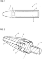
- Fig. 1 shows in the form of a pure schematic representation of a projectile according to the invention 1, consisting of a projectile casing 2, in which the actual explosive 3 is added, and one attached to the projectile casing 2 via a screw projectile nose 4, which has an igniter 5, the defined ignition of Explosives 3 serves.
- a bullet which is an ammunition, for example, the caliber 76 mm x 636, but also to a warhead or the like, is well known.
- the projectile 1 according to the invention is characterized in that the projectile nose 4 is defined relative to the projectile casing 2 and axially movable limited stop, wherein the axial movement is initiated solely by an overpressure caused in the interior of the projectile by outgassing of the explosive 3, and means are provided in order to reduce the overpressure as a result of the axial movement.
- the projectile tip 4 is in a sectional view in Fig. 2 shown. It comprises on the one hand a housing 6, which can also be addressed as an igniter housing.
- a Zündverproofrany 7 is screwed tight, including the housing 6 has an internal thread 8 and the ZündverEntrany 7 on a pin 9 has an external thread 10.
- the projectile tip is thus formed by the housing 6, the ignition amplifier carrier 7 and the igniter unit 11.
- the Zündverwoodrany 7 and thus the projectile nose 4 has an external thread 12, which is interrupted over a plurality of circumferentially equidistantly distributed longitudinal grooves 13, the venting channels respectively parts of venting channels, and this is ultimately weakened defined.
- the longitudinal grooves 13 go in continuing Grooves 14, so that ultimately this section has a plurality of individual ventilation channels 15.
- the front view according to Fig. 4 clearly shows the individual adjacent venting channels 15.
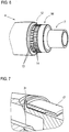
- Fig. 6 shows a perspective view of the projectile nose 4, on which the ZündverSchlochrrien 7 is mounted together with ignition unit 11.
- On the first external thread 12 is (see Fig. 7 ) now a first ring 17, the, see Fig. 8 , having an internal thread 18, screwed. It is screwed on until it rests against a radial flange 31 of the ZündverEntrities 7. Due to the formation of the longitudinal grooves 13 in conjunction with the fact that the external thread 12 is axially seen relatively short and results from screwing of internal thread 18 and external thread 12, a relatively weak threaded connection that holds no too large axial forces.
- the projectile nose 4 is axially fixed relative to the projectile casing 2, on the other hand, however, this threaded connection can be solved due to pressure to move the projectile tip 4 of the threaded sleeve 2 for venting purposes. This will be discussed below.
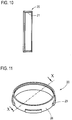
- FIG. 8 shows, the first ring 17 on an enlarged diameter portion 19.
- This section 19 makes it possible to see a second ring 20, which Fig. 10 , an internal thread 21, to screw on the second external thread 16 and at the same time to guide under the first ring 17, see Fig. 9 , D. h., That the first ring 17 axially overlaps the second ring 20 slightly, in which case an annular gap 22 is formed.
- the external thread 16 and the internal thread 21 are a substantially stronger mechanical connection, as the external thread 12 and the internal thread 18. For it is to ensure that the second ring 20 and the ZündverStorerany 7 are fixed and undetachably connected to each other under pressure.
- a plurality of radial projections 23 are provided, which form the second ring 20 as a stop element. Because these radial projections 23 beat when the projectile nose 4 is moved axially due to pressure, against a stop 24, formed over the end edge 25 of the first ring 17, and thus limit the axial movement, which will be discussed below. Since the radial projections 23 are circumferentially spaced from each other and thus given a radially lower intermediate region 26 between each two radial projections 23, there is consequently, see Fig. 9 , an immediate access to the annular gap 22 and via this to the venting channels 15th
- the projectile tip 4 can be screwed into the projectile casing 2.
- the projectile casing 2 has an internal thread 27 into which an external thread 28 provided on the first ring 17 is screwed.
- This threaded connection is also designed to be very strong mechanically, so that it is ensured that it is axially stable when pressure is applied to the projectile nose 4 and is not deformed.
- Fig. 12 shows the annular gap 22 between the first ring 17 and second ring 20, as well as the axial gap 29 between the end edge 25 of the first ring and the leading edge of the radial projections 23 of the second ring 20th
- Fig. 12 shows the mounting position, in which consequently a firm and tight connection between the projectile nose 4 and projectile casing 2 is given. Obviously, the leading end edge 30 of the projectile casing 2 is fixed and tight against the opposite end face 32 of the housing 6 and the radial flange 31 of the ZündverEntrlys 7.
- annular gap 33 opens radially outwardly.
- annular gap 33 all the longitudinal grooves 13 respectively venting passages 15. Since on the one hand the radial projections 23 are circumferentially spaced and open intermediate portions 26 are given, and on the other hand, there is also an annular gap 22 between the two rings 17 and 20 which leads into the venting channels 15, thus a complete venting path is given, from the interior of the projectile casing 2 in the annular gap 33 and from there leads to the outside.
Landscapes
- Engineering & Computer Science (AREA)
- General Engineering & Computer Science (AREA)
- Aiming, Guidance, Guns With A Light Source, Armor, Camouflage, And Targets (AREA)
Description
- Die Erfindung betrifft ein Geschoss, umfassend eine Geschosshülle mit darin aufgenommenem Sprengstoff, in die eine Geschossspitze enthaltend einen Zünder eingesetzt ist.
- Ein Geschoss der in Rede stehenden Art besteht aus einer Geschosshülle, in der der eigentliche Sprengstoff aufgenommen ist. In diese zumeist hohlzylindrische Geschosshülle wird die Geschossspitze enthaltend den Zünder üblicherweise mit hohem Drehmoment eingeschraubt. Wird ein solches Geschoss beispielsweise im Brandfall hohen Temperaturen ausgesetzt, so beginnt der Sprengstoff bedingt durch die erhöhte Temperatur im Inneren des Geschosses auszugasen. Es bildet sich also ein hoher Innendruck, der, da die Geschossspitze fest in die Geschosshülle eingeschraubt ist und folglich eine dichte Verbindung gegeben ist, durch Entweichen des sich bildenden Gases nicht abgebaut werden kann. Der Sprengstoff ist folglich sehr stark verdämmt. Bei einer kritischen Temperatur, der Reaktionstemperatur des Sprengstoffs, setzt der Sprengstoff um, es kommt folglich zur Explosion. Infolge des hohen Innendrucks ist diese Reaktion sehr heftig, verbunden mit Gefahren für die Umgebung. Mitunter kommt es auch druckbedingt zu einem Abtrennen der Geschossspitze von der Geschosshülle, so dass das Geschoss quasi in mehrere Teile zerfällt. Gleichwohl besteht infolge der hohen Temperatur die Gefahr, dass der Sprengstoff reagiert und es infolge der Einzelteile, die bei Reaktion des Sprengstoffs umherfliegen, zu einer Gefährdung der Umgebung kommt.
- Um dem entgegenzuwirken ist sogenannte "insensitive Munition", kurz IM-fähige Geschosse, bekannt. Bei einem solchen Geschoss sind Vorkehrungen getroffen, den sich bei Temperaturerhöhung ergebenden hohen Innendruck gezielt zu reduzieren, so dass bei hoher Funktionszuverlässigkeit die Wahrscheinlichkeit einer ungewollten Zündung des enthaltenden Sprengstoffs durch äußere Einflüsse wie Brand, Beschuss, Splittereinschlag oder andere Unfälle reduziert wird und damit die Gefahr von Kollateralschäden für die Waffenstation, Waffenträger und auch das Personal verringert wird. Ein Beispiel für eine solche IM-fähige Munition ist aus der
US 2010/0024675 A1 und aus derUS 7,353,755 B2 bekannt. In derUS 7,353,755 B2 ist der Zünder in einem Bauteil aufgenommen, das Sollbruchstellen aufweist. Ferner sind mehrere nach außen führende Entlüftungskanäle vorgesehen, die über Kunststoffpfropfen verschlossen sind. Kommt es bedingt durch eine Temperaturerhöhung zu einem Ausgasen des in der Geschosshülle abgedichtet aufgenommenen Sprengstoffs, so brechen ab Erreichen eines definierten Mindestinnendrucks die Sollbruchstellen an dem Bauteil, so dass der Druck in Richtung der über die Kunststoffpfropfen verschlossenen Entlüftungskanäle entweichen kann. Die nur leicht gehalterten Kunststoffstopfen werden durch den hohen Druck nach außen gedrückt, so dass die Entlüftungskanäle geöffnet werden und der Druck abgebaut werden kann. Einerseits liegen also auch hier Einzelteile, nämlich die Kunststoffpfropfen vor, andererseits ist nicht ausgeschlossen, dass sich bei sehr hohem Innendruck der Zünder respektive die Geschossspitze nicht doch von der Geschosshülle löst, insbesondere wenn sich aus welchem Grund auch immer die Sollbruchstelle nicht oder nicht vollständig öffnet. - Der Erfindung liegt damit die Aufgabe zugrunde, ein Geschoss anzugeben, das einerseits die Möglichkeit der Entlüftung und damit des Druckabbaus, bietet, andererseits aber ein Abtrennen der Geschossspitze von der Geschosshülle verhindert.
- Diese Aufgabe wird durch ein Geschoss gemäß Anspruch 1 gelöst. Vorteilhafte Ausführungsformen der Erfindung sind in den abhängigen Ansprüchen angegeben.
- Das erfindungsgemäße Geschoss, bei dem es sich um jedwede Geschossart und auch um einen Gefechtskopf handeln kann, zeichnet sich dadurch aus, dass eine druckbedingte definierte axiale Relativbeweglichkeit von Geschossspitze zur Geschosshülle vorgesehen ist. Diese Relativbeweglichkeit führt zum einen zur definierten Öffnung wenigstens eines Entlüftungskanals, über den der hohe Innendruck abgebaut werden kann. Zum anderen ist diese Bewegung definiert anschlagbegrenzt, d. h., die Geschossspitze ist nur ein definiertes axiales Stück bewegbar und läuft dann gegen einen Anschlag. Da es infolge des Öffnens des Entlüftungskanals bereits zu einem Druckabbau kommt, wird die Geschossspitze über den Anschlag sicher zurückgehalten, kann sich also nicht von der Geschosshülle separieren. Das erfindungsgemäße Geschoss zeichnet sich folglich durch die Integration einer zusätzlichen mechanischen Kopplung aus, die es ermöglicht, die Entlüftung wie auch die Rückhaltung der Geschossspitze respektive des Zünders auf der Geschosshülle miteinander zu kombinieren. Eine Separation respektive ein Anfall etwaiger Einzelteile ist bei dem erfindungsgemäßen Geschoss folglich ausgeschlossen.
- Zur Realisierung der begrenzten axialen Beweglichkeit ist es erfindungsgemäß vorgesehen, dass die Geschossspitze ein Außengewinde aufweist, auf das ein ein Innengewinde aufweisender erster Ring aufgeschraubt ist, der ein Außengewinde aufweist, das in ein Innengewinde der Geschosshülle eingeschraubt ist, und dass an der Geschossspitze ein Anschlagelement vorgesehen ist, das zur Begrenzung der axialen Bewegung, die durch ein druckbedingtes Abscheren der Gewindeverbindung des Rings mit der Geschossspitze ermöglicht wird, gegen den Anschlag läuft. Die axiale Beweglichkeit wird gemäß dieser Erfindungsausgestaltung dadurch realisiert, dass mit dem Außengewinde der Geschossspitze und dem darauf aufgeschraubten Innengewinde des Rings eine Gewindeverbindung realisiert wird, die so ausgelegt ist, dass sie bei Anlegen einer definierten axial gerichteten Kraft, die durch den hohen Innendruck erzeugt wird, abschert, mithin also die Gewindeverbindung zerstört wird. Aufgrund dieser dann nicht mehr gegebenen axialen Fixierung der Geschossspitze an dem Ring, der seinerseits fest mit der Geschosshülse verschraubt ist, kann die Geschossspitze ein kurzes Stück axial druckgetrieben soweit wandern, bis das Anschlagelement der Geschossspitze gegen den Anschlag läuft. Diese Gewindeverbindung stellt folglich eine Art "Sollbruchstelle" des Systems dar. Zur Ermöglichung des Abscherens sind unterschiedliche Ausgestaltungen der Gewindeverbindung denkbar, beispielsweise können die ineinandergreifenden Gewinde relativ flach ausgeführt sein, d. h., dass beide eine geringe Gewindetiefe aufweisen und folglich nur geringfügig ineinandergreifen. Auch ist es denkbar, die jeweiligen Gewinde durch axiale Ausfräsungen zu schwächen, so dass die Eingriffsfläche insgesamt reduziert wird und Ähnliches. Ziel der Auslegung der Gewindeverbindung ist es, dass ein relativ niedriger Druck auf die Geschossspitze respektive den Zünder ausreicht, die Gewindeflanken abzuscheren.
- Wie beschrieben ist geschossspitzenseitig ein Anschlagelement vorgesehen, das gegen einen mit der Geschosshülle positionsfesten Anschlag läuft. Dieses Anschlagelement kann in Weiterbildung der Erfindung als zweiter Ring ausgeführt sein, der mit einem Innengewinde auf das Außengewinde der Geschossspitze aufgeschraubt ist. Auf dieses geschossspitzenseitige Außengewinde sind gemäß dieser Erfindungsausgestaltung also zwei Ringe aufgeschraubt, nämlich zum einen der erste Ring, der die definierte, abscherbare Gewindeverbindung mit der Geschossspitze eingeht, zum anderen ein zweiter Ring, der das Anschlagelement darstellt. Die Gewindeverbindung, die das Innengewinde des zweiten Rings mit dem Außengewinde der Geschossspitze eingeht, ist mechanisch wesentlich fester ausgelegt als die abscherbare Gewindeverbindung. Denn diese zweite Gewindeverbindung soll in keinem Fall druckbedingt beschädigt werden, vielmehr soll sie so stabil sein, dass die Geschossspitze, wenn sie gegen den Anschlag läuft, sicher fixiert ist. Aus diesem Grund darf es zu keinem Zeitpunkt zu einem Lösen respektive einer Beschädigung dieser Gewindeverbindung kommen. Denkbar ist es, das Außengewinde der Geschossspitze in diesem Bereich tiefer zu schneiden, so dass das entsprechend geschnittene Innengewinde tiefer eingreift und folglich die Gewindeflanken größerflächig anliegen. Ist das Außengewinde der Geschossspitze durchgängig gleich, und ist es bei der Gewindeverbindung zum ersten Ring beispielsweise durch Längsfräsungen lokal abgetragen, so kann es im Bereich der Verbindung zum zweiten Ring durchgängig sein, so dass eine vergleichsweise größere Gewindeeingriffsfläche gegeben ist etc.
- In Weiterbildung der Erfindung kann schließlich vorgesehen sein, dass am zweiten Ring ein oder mehrere, vorzugsweise äquidistant um den Ringumfang verteilt angeordnete Radialvorsprünge vorgesehen sind, mit dem oder denen der zweite Ring gegen den Anschlag läuft. Der zweite Ring weist also einen oder mehrere Radialvorsprünge auf, die quasi als Anschlagabschnitte dienen und in der definierten Endstellung an den Anschlag anschlagen. Der Anschlag selbst wird vorzugsweise von der Stirnkante des ersten Rings gebildet, d. h., dass der erste Ring, der fest mit der Gehäusehülle verschraubt ist, das eine wegbegrenzende Element ist, während, sofern vorgesehen, der zweite Ring das zweite wegbegrenzende Element darstellt.
- Zur Ermöglichung eines kompakten Aufbaus ist es zweckmäßig, wenn der erste Ring einen das Innengewinde aufweisenden ersten Ringabschnitt und einen daran anschließenden zweiten Ringabschnitt mit vergrößertem Innendurchmesser aufweist, mit dem der erste Ring den zweiten Ring axial gesehen abschnittsweise radial übergreift. D. h., dass der zweite Ring quasi ein Stück weit unter den ersten Ring geschraubt wird, so dass sich hinreichend lange Gewindeeingriffe ergeben, gleichzeitig aber auch ein kompakter Aufbau gegeben ist. Fungiert der erste Ring mit seiner Stirnkante als Anschlag und schlägt der zweite Ring beispielsweise über den oder die Radialvorsprünge an der Stirnkante an, so kann durch entsprechend weites Aufschrauben des zweiten Rings und damit Bewegen unter den ersten Ring der axiale Spalt zwischen dem oder den Radialvorsprüngen und der Stirnkante definiert eingestellt werden, folglich also auch die axiale Beweglichkeit.
- Wie beschrieben wird mit dem Bewegen respektive spätestens mit Erreichen der Endstellung der Geschossspitze nach Abscheren der Gewindeverbindung wenigstens ein Entlüftungskanal geöffnet. Da wie beschrieben die Geschossspitze sich axial von der Geschosshülse wegbewegt, wird folglich hierbei ein radial nach außen offener Ringkanal geöffnet, der es ermöglicht, hierüber den Überdruck abzubauen. Um dies zu ermöglichen ist zweckmäßigerweise das Außengewinde der Geschossspitze und/oder das Innengewinde des ersten Rings mit wenigstens einer Längsnut versehen, die den Entlüftungskanal oder einen Teil davon bildet und die in einem sich bei Erreichen der Anschlagposition zwischen Geschossspitze und Geschosshülle nach außen öffnenden Ringspalt mündet. Die Gewindeverbindung, die bei Überdruck abgeschert wird, ist also mit einer, bevorzugt mit einer Vielzahl von äquidistanten und um den Umfang verteilt angeordneten Längsnuten versehen, die den respektive die Lüftungskanäle oder Teile davon bilden. Diese dienen darüber hinaus gleichzeitig der Schwächung des Gewindes, um ein definiertes Abscheren zu ermöglichen. In der Montagestellung, wenn die Geschossspitze fest und dicht an der Geschosshülle verschraubt ist, ist das gesamte Innere komplett abgedichtet, folglich auch dieser oder diese Entlüftungskanäle geschlossen. Baut sich nun ein hoher Innendruck auf und kommt es zum Abscheren des Gewindes, so bewegt sich die Geschossspitze ein kurzes Stück axial von der Gewindehülle weg, es öffnet sich ein radial nach außen offener Ringspalt, in dem der oder die gewindeverbindungsseitigen Längsnuten, also die Entlüftungskanäle, münden. Das Innere kommuniziert in geeigneter Weise mit dem oder den Längsnuten, so dass der Überdruck hierüber in den Ringkanal entweichen kann. Der Überdruck wird abgebaut, gleichwohl ist die Geschossspitze sicher in der Geschosshülle über den Anschlag gefangen.
- Um den Überdruck respektive das entstehende Gas in die eine oder die mehreren Längsnuten zu führen ist es zweckmäßig, wenn der erste Ring den zweiten Ring mit radialem Abstand übergreift, sodass sich ein Ringspalt bildet, der mit der wenigstens einen Längsnut respektive der Vielzahl der umfangsmäßig verteilt vorgesehenen Längsnuten und dem Geschossinneren kommuniziert. D. h., dass das sich bildende Gas letztlich vom Geschossinneren kommend in den Ringspalt zwischen dem ersten und dem zweiten Ring strömt und von dort in die eine oder die mehreren Längsnuten strömt, von wo aus es in den sich öffnenden Radialspalt abgeführt wird. Selbstverständlich wäre es auch denkbar, das Gas unmittelbar in die Längsnut(en) zu führen, beispielsweise wenn kein zweiter Ring vorgesehen ist und fertigungstechnisch einstückig an der Geschossspitze ein oder mehrere Anschlagelemente radial vorspringend vorgesehen wären. Denn dann wäre, nachdem der erste Ring axial gesehen quasi an das Hülleninnere anschließt, der Zugang zu der oder den Entlüftungsnuten ohnehin offen.
- Weitere Vorteile, Merkmale und Einzelheiten der Erfindung ergeben sich aus den im Folgenden beschriebenen Ausführungsbeispielen sowie anhand der Zeichnung. Dabei zeigen:
- Fig. 1
- eine Prinzipdarstellung eines erfindungsgemäßen Geschosses,
- Fig. 2
- eine perspektivische Schnittansicht durch die Geschossspitze enthaltend respektive darstellend den Zünder,
- Fig. 3
- eine Perspektivansicht des Zündverstärkerträgers,
- Fig. 4
- eine Stirnseitenansicht des Zündverstärkerträgers aus
Fig. 3 , - Fig. 5
- eine Schnittansicht des Zündverstärkerträgers aus
Fig. 3 , - Fig. 6
- eine Perspektivansicht der Geschossspitze lediglich mit montiertem Zündverstärkerträger,
- Fig. 7
- die Geschossspitze aus
Fig. 6 mit aufgeschraubtem ersten Ring, - Fig. 8
- eine Schnittansicht durch den ersten Ring,
- Fig. 9
- eine Perspektivansicht der Geschossspitze aus
Fig. 7 mit aufgeschraubtem zweiten Ring, - Fig. 10
- eine Schnittansicht durch den zweiten Ring,
- Fig. 11
- eine Perspektivansicht des zweiten Rings,
- Fig. 12
- eine Teilansicht eines erfindungsgemäßen Geschosses mit Schnittdarstellung des Verbindungsbereichs von Geschossspitze zu Geschosshülle in der Grundstellung, und
- Fig. 13
- die Darstellung aus
Fig. 12 mit druckbedingter Axialverschiebung der Geschossspitze relativ zur Geschosshülle. -
Fig. 1 zeigt in Form einer reinen Prinzipdarstellung ein erfindungsgemäßes Geschoss 1, bestehend aus einer Geschosshülle 2, in der der eigentliche Sprengstoff 3 aufgenommen ist, sowie einer an der Geschosshülle 2 über eine Schraubverbindung befestigte Geschossspitze 4, die einen Zünder 5 aufweist, der der definierten Zündung des Sprengstoffs 3 dient. Der grundsätzliche Aufbau eines solchen Geschosses, bei dem es sich um eine Munition beispielsweise vom Kaliber 76 mm x 636 handelt, aber auch um einen Gefechtskopf oder Ähnliches, ist hinlänglich bekannt. - Das erfindungsgemäße Geschoss 1 zeichnet sich dadurch aus, dass die Geschossspitze 4 relativ zur Geschosshülse 2 definiert und anschlagbegrenzt axial beweglich ist, wobei die axiale Bewegung allein durch einen im Inneren des Geschosses durch ein Ausgasen des Sprengstoffs 3 hervorgerufenen Überdruck initiiert wird, und Mittel vorgesehen sind, um, resultierend aus der Axialbewegung, den Überdruck abzubauen.
- Die Geschossspitze 4 ist in einer Schnittdarstellung in
Fig. 2 gezeigt. Sie umfasst zum einen ein Gehäuse 6, das auch als Zündergehäuse angesprochen werden kann. In dieses Gehäuse 6 ist ein Zündverstärkerträger 7 fest eingeschraubt, wozu das Gehäuse 6 ein Innengewinde 8 und der Zündverstärkerträger 7 an einem Zapfen 9 ein Außengewinde 10 aufweist. Am Zündverstärkerträger 7 ist die eigentliche Zündereinheit 11 umfassend einen SAD (safety & arming device) sowie eine oder mehrere Booster (= Zündverstärker) etc. aufgenommen. Die Geschossspitze wird also durch Gehäuse 6, Zündverstärkerträger 7 sowie Zündereinheit 11 gebildet. - Zur Ermöglichung einer axialen Beweglichkeit ist der Zündverstärkerträger 7, als Teil der Geschossspitze, siehe die
Fig. 3 bis 5 , in besonderer Weise ausgestaltet. Der Zündverstärkerträger 7 und damit die Geschossspitze 4 weist ein Außengewinde 12 auf, das über eine Vielzahl von umfangsmäßig äquidistant verteilte Längsnuten 13, die Entlüftungskanäle respektive Teile von Entlüftungskanälen bilden, unterbrochen ist und hierüber letztlich definiert geschwächt ist. Die Längsnuten 13 gehen in fortsetzende Nuten 14 über, so dass letztlich dieser Abschnitt über eine Vielzahl einzelner Entlüftungskanäle 15 verfügt. Die Stirnansicht gemäßFig. 4 zeigt deutlich die einzelnen nebeneinander liegenden Entlüftungskanäle 15. - An diesen Abschnitt schließt sich ein zweites Außengewinde 16 an, das, siehe
Fig. 5 , im Durchmesser etwas kleiner ist als das erste Außengewinde 12, das, wieFig. 5 zeigt, erhaben ist, während das Außengewinde 16 eingetieft ausgearbeitet ist. Diese unterschiedlichen Außengewinde 12 und 16 dienen der Aufnahme separater Ringe, worauf nachfolgend noch eingegangen werden wird. -
Fig. 6 zeigt eine Perspektivansicht der Geschossspitze 4, an der der Zündverstärkerträger 7 nebst Zündeinheit 11 montiert ist. Auf das erste Außengewinde 12 wird (sieheFig. 7 ) nun ein erster Ring 17, der, sieheFig. 8 , ein Innengewinde 18 aufweist, aufgeschraubt. Er wird soweit aufgeschraubt, bis er an einem Radialflansch 31 des Zündverstärkerträgers 7 anliegt. Infolge der Ausbildung der Längsnuten 13 in Verbindung mit dem Umstand, dass das Außengewinde 12 axial gesehen relativ kurz ist und ergibt sich durch Verschrauben von Innengewinde 18 und Außengewinde 12 eine relativ schwache Gewindeverbindung, die keinen allzu großen Axialkräften Stand hält. Dies ist vorliegend wichtig, als über diese Gewindeverbindung zwar einerseits die Geschossspitze 4 axial gesehen relativ zur Geschosshülle 2 festgelegt wird, andererseits aber auch diese Gewindeverbindung druckbedingt gelöst werden kann, um die Geschossspitze 4 von der Gewindehülse 2 zu Entlüftungszwecken wegzubewegen. Hierauf wird nachfolgend noch eingegangen. - Wie
Fig. 8 zeigt, weist der erste Ring 17 einen im Durchmesser vergrößerten Abschnitt 19 auf. Dieser Abschnitt 19 ermöglicht es, einen zweiten Ring 20, der, sieheFig. 10 , ein Innengewinde 21 aufweist, auf das zweite Außengewinde 16 aufzuschrauben und gleichzeitig unter den ersten Ring 17 zu führen, sieheFig. 9 . D. h., dass der erste Ring 17 den zweiten Ring 20 axial gesehen etwas übergreift, wobei sich hierbei ein Ringspalt 22 ausbildet. Das Außengewinde 16 und das Innengewinde 21 gehen eine wesentlich fester mechanische Verbindung ein, als das Außengewinde 12 und das Innengewinde 18. Denn es ist sicherzustellen, dass der zweite Ring 20 und der Zündverstärkerträger 7 fest und auch bei Druckbeaufschlagung unlösbar miteinander verbunden sind. - Am zweiten Ring 20 sind, siehe
Fig. 11 , mehrere Radialvorsprünge 23 vorgesehen, die den zweiten Ring 20 als Anschlagelement ausbilden. Denn diese Radialvorsprünge 23 schlagen, wenn die Geschossspitze 4 druckbedingt axial bewegt wird, gegen einen Anschlag 24, gebildet über die Stirnkante 25 des ersten Rings 17, und begrenzen so die Axialbewegung, worauf nachfolgend noch eingegangen werden wird. Da die Radialvorsprünge 23 umfangsmäßig gesehen voneinander beabstandet sind und folglich ein radial tieferliegender Zwischenbereich 26 zwischen jeweils zwei Radialvorsprüngen 23 gegeben ist, ergibt sich folglich, sieheFig. 9 , ein unmittelbarer Zugang zum Ringspalt 22 und über diesen zu den Entlüftungskanälen 15. - Ist der zweite Ring 20 verschraubt, so kann die Geschossspitze 4 in die Geschosshülle 2 eingeschraubt werden. Hierzu weist die Geschosshülle 2 ein Innengewinde 27 auf, in das ein am ersten Ring 17 vorgesehenes Außengewinde 28 eingeschraubt wird. Diese Gewindeverbindung ist ebenfalls mechanisch sehr fest ausgelegt, so dass sichergestellt ist, dass sie bei einer Druckbeaufschlagung der Geschossspitze 4 axial gesehen stabil ist und nicht deformiert wird.
- Es sind folglich nach Verschrauben der Geschossspitze insgesamt drei Gewindeverbindungen gegeben, nämlich zum einen die geschwächte und zur Abscherung vorgesehene Gewindeverbindung aus Außengewinde 12 und Innengewinde 18 zwischen dem ersten Ring 17 und der Geschossspitze 4 respektive des Zündverstärkerträgers 7, weiterhin die zweite, mechanisch feste Gewindeverbindung aus Außengewinde 16 des Zündverstärkerträgers 7 und Innengewinde 21 des zweiten Rings 20, sowie als dritte Gewindeverbindung die ebenfalls mechanisch sehr feste Verbindung zwischen Außengewinde 28 und Innengewinde 27 der Geschosshülle 2.
-
Fig. 12 zeigt zum anderen den Ringspalt 22 zwischen erstem Ring 17 und zweitem Ring 20, wie auch den Axialspalt 29 zwischen der Stirnkante 25 des ersten Rings und der vorlaufenden Kante der Radialvorsprünge 23 des zweiten Rings 20. -
Fig. 12 zeigt die Montagestellung, in der folglich eine feste und dichte Verbindung zwischen Geschossspitze 4 und Geschosshülle 2 gegeben ist. Ersichtlich liegt die vorlaufende Stirnkante 30 der Geschosshülle 2 fest und dicht an der gegenüberliegenden Stirnfläche 32 des Gehäuses 6 respektive dem Radialflansch 31 des Zündverstärkerträgers 7 an. - Kommt es nun temperaturbedingt zu einem Ausgasen des Sprengstoffs 3 in der Geschosshülle 2 und damit zu einem hohen Innendruck, so wirkt dieser unmittelbar auf die Geschossspitze 4 respektive den Zündverstärkerträger 7 nebst Zündeinheit 11. Solange der Innendruck und daraus resultierend die axiale Kraft, die auf die erste Gewindeverbindung zwischen Außengewinde 12 des Zündverstärkerträgers 7 und Innengewinde 18 des ersten Rings 17 wirkt, noch hinreichend gering ist, dass die Gewindeverbindung sie noch aufnimmt, bleibt es bei der in
Fig. 12 gezeigten Position von Geschossspitze 4 und Geschosshülle 2. Steigt der Druck jedoch weiter, so nimmt die axiale Kraft zu. Ist sie hinreichend groß, hält die Gewindeverbindung zwischen erstem Ring 17 und Zündverstärkerträger 7 dem nicht mehr Stand, die Gewindegänge respektive Gewindeflanken werden abgeschert. Es kommt nun, sieheFig. 13 , zu einer Axialbewegung der Geschossspitze 4 relativ Geschosshülle 2, da infolge des abgescherten Gewindes die Geschossspitze 4 axial gesehen nicht mehr fest mit der Geschosshülle 2 verbunden ist. Diese Axialbewegung ist anschlagbegrenzt, d. h., die Geschossspitze 4 bewegt sich soweit, bis die Radialvorsprünge 23 des zweiten Rings 20 an der Stirnkante 25 des ersten Rings 17 anschlagen. Eine weitere Bewegung ist ausgeschlossen. Denn einerseits ist die Gewindeverbindung von zweitem Ring 20 zum Zündverstärkerträger 7 und damit zur Geschossspitze 4 intakt, zum anderen ist die Gewindeverbindung zwischen Geschosshülle 2 und erstem Ring 17 ebenfalls intakt. - Mit dem Abscheren der Gewindeverbindung zwischen erstem Ring 17 und Zündverstärkerträger 7, respektive Geschossspitze 4, und der daraus resultierenden Axialbewegung öffnet sich ein radial nach außen offener Ringspalt 33. In diesen Ringspalt 33 münden nun sämtliche Längsnuten 13 respektive Entlüftungskanäle 15. Da einerseits die Radialvorsprünge 23 umfangsmäßig beabstandet sind und offene Zwischenabschnitte 26 gegeben sind, und da andererseits auch ein Ringspalt 22 zwischen den beiden Ringen 17 und 20 gegeben ist, der in die Entlüftungskanäle 15 führt, ist somit ein kompletter Entlüftungspfad gegeben, der vom Inneren der Geschosshülle 2 in den Ringspalt 33 und von dort nach außen führt. Der hohe Innendruck, der zum Teil bereits durch die Axialbewegung abgebaut wurde, wird nun komplett abgebaut, es kommt zur Entlüftung des Geschossinneren über den Zündverstärkerträger 7, respektive die Geschossspitze 4. Gleichzeitig ist eine sichere Rückhaltung der Geschossspitze 4 respektive des Zünders gegeben, es kommt also nicht zu einer Vereinzelung der diversen Teile. Ermöglicht wird dies bei dem konkreten Ausführungsbeispiel durch die Verwendung des ersten Rings 17 und des zweiten Rings 20 sowie die entsprechende Ausbildung der jeweiligen Außen- und Innengewinde an den Ringen 17, 20 respektive der Geschossspitze 4 bzw. dem Zündverstärkerträger 7 und der Geschosshülle 2.
Claims (10)
- Geschoss, umfassend eine Geschosshülle (2) mit darin aufgenommenem Sprengstoff (3), in die eine Geschossspitze (4) enthaltend einen Zünder (5) eingesetzt ist, wobei die Geschossspitze (4) durch einen sich im Inneren des Geschosses (1) aufbauenden Gasdruck relativ zur Geschosshülle (2) axial gegen einen Anschlag (24) unter Öffnung wenigstens eines das Innere der Geschosshülle (2) mit der Umgebung verbindenden Entlüftungskanals (16) bewegbar ist,
wobei die Geschossspitze (4) ein Außengewinde (12) aufweist, auf das ein ein Innengewinde (18) aufweisender erster Ring (17) aufgeschraubt ist, der ein Außengewinde (28) aufweist, das in ein Innengewinde (27) der Geschosshülle (2) eingeschraubt ist, und wobei an der Geschossspitze (4) ein Anschlagelement (20) vorgesehen ist, das zur Begrenzung der axialen Bewegung, die durch ein druckbedingtes Abscheren der Gewindeverbindung des Rings (17) mit der Geschossspitze (4) ermöglicht wird, gegen den Anschlag (24) läuft. - Geschoss nach Anspruch 1,
dadurch gekennzeichnet,
dass das Anschlagelement ein zweiter Ring (20) ist, der mit einem Innengewinde (21) auf das oder ein weiteres Außengewinde (15) der Geschossspitze (4) geschraubt ist. - Geschoss nach Anspruch 2,
dadurch gekennzeichnet,
dass am zweiten Ring (20) ein oder mehrere, vorzugsweise äquidistant um den Ringumfang verteilt angeordnete Radialvorsprünge (23) vorgesehen sind, mit dem oder denen der zweite Ring (20) gegen den Anschlag (24) läuft. - Geschoss nach Anspruch 2 oder 3,
dadurch gekennzeichnet,
dass der erste Ring (17) und der zweite Ring (20) auf einen Zündverstärkerträger (7), der Teil der Geschossspitze (4) ist und der das oder die Außengewinde (12, 15) aufweist, aufgeschraubt sind. - Geschoss nach einem der vorangehenden Ansprüche,
dadurch gekennzeichnet,
dass der Anschlag (24) von der Stirnkante (25) des ersten Rings (17) gebildet ist. - Geschoss nach Anspruch 5,
dadurch gekennzeichnet,
dass der erste Ring (17) einen das Innengewinde (18) aufweisenden ersten Ringabschnitt und einen daran anschließenden zweiten Ringabschnitt (19) mit vergrößertem Innendurchmesser aufweist, mit dem der erste Ring (17) den zweiten Ring (20) axial gesehen abschnittsweise radial übergreift. - Geschoss nach einem der vorangehenden Ansprüche,
dadurch gekennzeichnet,
dass das Außengewinde (12) der Geschossspitze (4) und/oder das Innengewinde (18) des ersten Rings (17) mit wenigstens einer Längsnut (13) aufweist, die den Entlüftungskanal (16) oder einen Teil davon bildet und in einem sich bei Erreichen der Anschlagposition zwischen Geschossspitze (4) und Geschosshülle (2) nach außen öffnenden Ringspalt (33) mündet. - Geschoss nach Anspruch 7,
dadurch gekennzeichnet,
dass am Außengewinde (12) und/oder am Innengewinde (18) mehrere äquidistant um den Umfang verteilt angeordnete Längsnuten (13) vorgesehen sind. - Geschoss nach Anspruch 6 und 7,
dadurch gekennzeichnet,
dass der erste Ring (17) den zweiten Ring (20) mit radialem Abstand übergreift und der gegebene Ringspalt (22) mit der wenigstens einen Längsnut (13) kommuniziert und dem Geschossinneren kommuniziert. - Geschoss nach einem der vorangehenden Ansprüche,
dadurch gekennzeichnet,
dass die axiale Beweglichkeit wenigstens 1mm, vorzugsweise wenigstens 2 mm beträgt.
Applications Claiming Priority (1)
| Application Number | Priority Date | Filing Date | Title |
|---|---|---|---|
| DE201310014811 DE102013014811B4 (de) | 2013-09-05 | 2013-09-05 | Geschoss |
Publications (2)
| Publication Number | Publication Date |
|---|---|
| EP2846124A1 EP2846124A1 (de) | 2015-03-11 |
| EP2846124B1 true EP2846124B1 (de) | 2018-06-06 |
Family
ID=51421806
Family Applications (1)
| Application Number | Title | Priority Date | Filing Date |
|---|---|---|---|
| EP14002970.3A Active EP2846124B1 (de) | 2013-09-05 | 2014-08-27 | Geschoss |
Country Status (3)
| Country | Link |
|---|---|
| EP (1) | EP2846124B1 (de) |
| DE (1) | DE102013014811B4 (de) |
| ZA (1) | ZA201406456B (de) |
Families Citing this family (1)
| Publication number | Priority date | Publication date | Assignee | Title |
|---|---|---|---|---|
| DE102016008391B4 (de) | 2016-07-09 | 2018-05-24 | Diehl Defence Gmbh & Co. Kg | Geschoss |
Citations (25)
| Publication number | Priority date | Publication date | Assignee | Title |
|---|---|---|---|---|
| GB191502724A (en) | 1913-11-19 | 1917-06-28 | Cie Forges Et Acieries Marine | Multiple Effect Fuse for Artillery Projectiles. |
| US1292505A (en) | 1917-03-03 | 1919-01-28 | Westinghouse Air Brake Co | Percussion-fuse for projectiles. |
| DE350905C (de) | 1920-05-20 | 1922-03-28 | Carl Puff | Aufschlagzuender fuer Abwurfgeschosse |
| DE353115C (de) | 1922-05-08 | Otto Wilhelmi | Mit Fluessigkeit gefuelltes Sprenggeschoss | |
| GB343859A (en) | 1930-05-16 | 1931-02-26 | Edgar William Brandt | Projectile with numerous applications |
| GB552587A (en) | 1940-10-18 | 1943-04-15 | Cameron Alexander Whitsett | Improvements in or relating to anti-aircraft shells of the type containing a parachute mine |
| DE1127251B (de) | 1960-04-02 | 1962-04-05 | Bofors Ab | Geschosszuender |
| AT228098B (de) | 1960-05-18 | 1963-06-25 | Oerlikon Buehrle Ag | Aufschlagzünder für Geschosse |
| AT271269B (de) | 1966-03-11 | 1969-05-27 | Oerlikon Buehrle Holding Ag | Elektrischer Aufschlag-Kopfschalter für Geschosse |
| DE2611064A1 (de) | 1975-04-03 | 1976-10-14 | Oerlikon Buehrle Ag | Flugkoerper mit einem geschosskopf |
| US4557198A (en) | 1982-03-04 | 1985-12-10 | The Secretary Of State For Defence In Her Britannic Majesty's Government Of The United Kingdom Of Great Britain And Northern Ireland | Safety devices for carrier shells |
| EP0334731A1 (de) | 1988-03-18 | 1989-09-27 | Societe Des Ateliers Mecaniques De Pont Sur Sambre (Samp) | Gerät zum Entsichern eines militärischen Explosionskörpers |
| US4991513A (en) | 1990-03-12 | 1991-02-12 | The United States Of America As Represented By The Secretary Of The Navy | Carrier projectile with safety vents |
| US5035181A (en) | 1985-01-22 | 1991-07-30 | The United States Of America As Represented By The Secretary Of The Navy | Thermosensitive pop-out device |
| US5119715A (en) | 1991-07-02 | 1992-06-09 | Raytheon Company | Time delay fuze |
| FR2742221A1 (fr) | 1995-12-12 | 1997-06-13 | Soc D Ateliers Mecaniques De P | Dispositif de deconfinement pour munition |
| DE29817728U1 (de) | 1998-10-05 | 1999-02-04 | Honeywell Ag, 63067 Offenbach | Geschoßzünderaufbau |
| US6523477B1 (en) | 1999-03-30 | 2003-02-25 | Lockheed Martin Corporation | Enhanced performance insensitive penetrator warhead |
| US7353755B2 (en) | 2003-12-22 | 2008-04-08 | Giat Industries | Deconfinement device for the casing of a piece of ammunition |
| US7472653B1 (en) | 2006-06-15 | 2009-01-06 | United States Of America As Represented By The Secretary Of The Navy | Insensitive munitions warhead explosive venting system |
| EP2053344A1 (de) | 2007-10-23 | 2009-04-29 | Tda Armements S.A.S. | Energetische Ladung mit kontrollierter Entsicherung und Munition, die mit einer solchen Ladung ausgerüstet ist |
| US20100024675A1 (en) | 2006-09-29 | 2010-02-04 | Nexter Munitions | Deconfinement device for the casing of a piece of an ammunition |
| US20120255456A1 (en) | 2009-08-19 | 2012-10-11 | Alliant Techsystems Inc. | Insensitive munitions swaged vent plug |
| FR2981443A1 (fr) | 2011-10-17 | 2013-04-19 | Sme | Generateur de gaz muni d'un organe de securite pour les cas d'echauffements lents |
| US8505458B1 (en) | 2012-01-27 | 2013-08-13 | The United States Of America As Represented By The Secretary Of The Navy | Venting cap system |
-
2013
- 2013-09-05 DE DE201310014811 patent/DE102013014811B4/de active Active
-
2014
- 2014-08-27 EP EP14002970.3A patent/EP2846124B1/de active Active
- 2014-09-03 ZA ZA2014/06456A patent/ZA201406456B/en unknown
Patent Citations (25)
| Publication number | Priority date | Publication date | Assignee | Title |
|---|---|---|---|---|
| DE353115C (de) | 1922-05-08 | Otto Wilhelmi | Mit Fluessigkeit gefuelltes Sprenggeschoss | |
| GB191502724A (en) | 1913-11-19 | 1917-06-28 | Cie Forges Et Acieries Marine | Multiple Effect Fuse for Artillery Projectiles. |
| US1292505A (en) | 1917-03-03 | 1919-01-28 | Westinghouse Air Brake Co | Percussion-fuse for projectiles. |
| DE350905C (de) | 1920-05-20 | 1922-03-28 | Carl Puff | Aufschlagzuender fuer Abwurfgeschosse |
| GB343859A (en) | 1930-05-16 | 1931-02-26 | Edgar William Brandt | Projectile with numerous applications |
| GB552587A (en) | 1940-10-18 | 1943-04-15 | Cameron Alexander Whitsett | Improvements in or relating to anti-aircraft shells of the type containing a parachute mine |
| DE1127251B (de) | 1960-04-02 | 1962-04-05 | Bofors Ab | Geschosszuender |
| AT228098B (de) | 1960-05-18 | 1963-06-25 | Oerlikon Buehrle Ag | Aufschlagzünder für Geschosse |
| AT271269B (de) | 1966-03-11 | 1969-05-27 | Oerlikon Buehrle Holding Ag | Elektrischer Aufschlag-Kopfschalter für Geschosse |
| DE2611064A1 (de) | 1975-04-03 | 1976-10-14 | Oerlikon Buehrle Ag | Flugkoerper mit einem geschosskopf |
| US4557198A (en) | 1982-03-04 | 1985-12-10 | The Secretary Of State For Defence In Her Britannic Majesty's Government Of The United Kingdom Of Great Britain And Northern Ireland | Safety devices for carrier shells |
| US5035181A (en) | 1985-01-22 | 1991-07-30 | The United States Of America As Represented By The Secretary Of The Navy | Thermosensitive pop-out device |
| EP0334731A1 (de) | 1988-03-18 | 1989-09-27 | Societe Des Ateliers Mecaniques De Pont Sur Sambre (Samp) | Gerät zum Entsichern eines militärischen Explosionskörpers |
| US4991513A (en) | 1990-03-12 | 1991-02-12 | The United States Of America As Represented By The Secretary Of The Navy | Carrier projectile with safety vents |
| US5119715A (en) | 1991-07-02 | 1992-06-09 | Raytheon Company | Time delay fuze |
| FR2742221A1 (fr) | 1995-12-12 | 1997-06-13 | Soc D Ateliers Mecaniques De P | Dispositif de deconfinement pour munition |
| DE29817728U1 (de) | 1998-10-05 | 1999-02-04 | Honeywell Ag, 63067 Offenbach | Geschoßzünderaufbau |
| US6523477B1 (en) | 1999-03-30 | 2003-02-25 | Lockheed Martin Corporation | Enhanced performance insensitive penetrator warhead |
| US7353755B2 (en) | 2003-12-22 | 2008-04-08 | Giat Industries | Deconfinement device for the casing of a piece of ammunition |
| US7472653B1 (en) | 2006-06-15 | 2009-01-06 | United States Of America As Represented By The Secretary Of The Navy | Insensitive munitions warhead explosive venting system |
| US20100024675A1 (en) | 2006-09-29 | 2010-02-04 | Nexter Munitions | Deconfinement device for the casing of a piece of an ammunition |
| EP2053344A1 (de) | 2007-10-23 | 2009-04-29 | Tda Armements S.A.S. | Energetische Ladung mit kontrollierter Entsicherung und Munition, die mit einer solchen Ladung ausgerüstet ist |
| US20120255456A1 (en) | 2009-08-19 | 2012-10-11 | Alliant Techsystems Inc. | Insensitive munitions swaged vent plug |
| FR2981443A1 (fr) | 2011-10-17 | 2013-04-19 | Sme | Generateur de gaz muni d'un organe de securite pour les cas d'echauffements lents |
| US8505458B1 (en) | 2012-01-27 | 2013-08-13 | The United States Of America As Represented By The Secretary Of The Navy | Venting cap system |
Also Published As
| Publication number | Publication date |
|---|---|
| DE102013014811B4 (de) | 2015-04-09 |
| ZA201406456B (en) | 2016-05-25 |
| EP2846124A1 (de) | 2015-03-11 |
| DE102013014811A1 (de) | 2015-03-05 |
Similar Documents
| Publication | Publication Date | Title |
|---|---|---|
| EP1502074B1 (de) | Teilzerlegungs- und deformationsgeschosse mit identischer treffpunktlage und verfahren zur herstellung eines solchen geschosses | |
| EP1851503B1 (de) | Geschoss | |
| EP0853228B1 (de) | Geschoss und Verfahren zu dessen Herstellung | |
| DE69213861T2 (de) | Unterkalibriges Wuchtgeschoss mit Splitterwirkung | |
| DE10205043C5 (de) | Aus einem Rohr zu verschließender Flugkörper mit überkalibrigem Leitwerk | |
| EP3507565B1 (de) | Geschoss mit penetrator | |
| EP2846124B1 (de) | Geschoss | |
| EP3312546B1 (de) | Mehrzweckgeschoss | |
| EP2212643B1 (de) | Geschoss | |
| DE2324482C3 (de) | Patronenhülse für Schlagzündung | |
| DE69110212T2 (de) | Dichtungsband für Pfeilgeschoss. | |
| DE202014103662U1 (de) | Bleifreies Teilzerlegungsgeschoss für Jagdzwecke | |
| DE590542C (de) | Panzergeschoss | |
| DE19736298B4 (de) | Verfahren und Vorrichtung zum Delaborieren von Granaten mit Hohlladung | |
| DE60007943T2 (de) | Verbindungsteil zwischen Geschoss und Geschosshülse und Methode zur Montage eines Dichtringes mittels eines derartigen Verbindungteiles | |
| DE102007016488B3 (de) | Penetrationsfähiges Geschoss | |
| EP2905572B1 (de) | Treibladungshülse für eine Patronenmunition | |
| EP2410284B1 (de) | Gefechtskopf | |
| EP3267143B1 (de) | Geschoss | |
| EP3137845A1 (de) | Patrone mit schmelzsicherung im antriebssystem und verfahren zu ihrer herstellung | |
| DE3804847C2 (de) | ||
| EP3457076B1 (de) | Wirkkörper mit bremsdeckel | |
| CH628979A5 (en) | Projectile impact fuze | |
| WO2008086784A2 (de) | Wälzlagerkäfig mit vereinfachtem einbau der wälzkörper | |
| EP3034989B1 (de) | Geschoss |
Legal Events
| Date | Code | Title | Description |
|---|---|---|---|
| 17P | Request for examination filed |
Effective date: 20140827 |
|
| AK | Designated contracting states |
Kind code of ref document: A1 Designated state(s): AL AT BE BG CH CY CZ DE DK EE ES FI FR GB GR HR HU IE IS IT LI LT LU LV MC MK MT NL NO PL PT RO RS SE SI SK SM TR |
|
| AX | Request for extension of the european patent |
Extension state: BA ME |
|
| PUAI | Public reference made under article 153(3) epc to a published international application that has entered the european phase |
Free format text: ORIGINAL CODE: 0009012 |
|
| R17P | Request for examination filed (corrected) |
Effective date: 20150827 |
|
| RBV | Designated contracting states (corrected) |
Designated state(s): AL AT BE BG CH CY CZ DE DK EE ES FI FR GB GR HR HU IE IS IT LI LT LU LV MC MK MT NL NO PL PT RO RS SE SI SK SM TR |
|
| RAP1 | Party data changed (applicant data changed or rights of an application transferred) |
Owner name: DIEHL DEFENCE GMBH & CO. KG |
|
| GRAP | Despatch of communication of intention to grant a patent |
Free format text: ORIGINAL CODE: EPIDOSNIGR1 |
|
| STAA | Information on the status of an ep patent application or granted ep patent |
Free format text: STATUS: GRANT OF PATENT IS INTENDED |
|
| RIC1 | Information provided on ipc code assigned before grant |
Ipc: F42B 30/08 20060101ALN20180112BHEP Ipc: F42B 39/20 20060101AFI20180112BHEP |
|
| INTG | Intention to grant announced |
Effective date: 20180212 |
|
| GRAS | Grant fee paid |
Free format text: ORIGINAL CODE: EPIDOSNIGR3 |
|
| GRAA | (expected) grant |
Free format text: ORIGINAL CODE: 0009210 |
|
| STAA | Information on the status of an ep patent application or granted ep patent |
Free format text: STATUS: THE PATENT HAS BEEN GRANTED |
|
| AK | Designated contracting states |
Kind code of ref document: B1 Designated state(s): AL AT BE BG CH CY CZ DE DK EE ES FI FR GB GR HR HU IE IS IT LI LT LU LV MC MK MT NL NO PL PT RO RS SE SI SK SM TR |
|
| REG | Reference to a national code |
Ref country code: GB Ref legal event code: FG4D Free format text: NOT ENGLISH |
|
| REG | Reference to a national code |
Ref country code: CH Ref legal event code: EP Ref country code: AT Ref legal event code: REF Ref document number: 1006590 Country of ref document: AT Kind code of ref document: T Effective date: 20180615 |
|
| REG | Reference to a national code |
Ref country code: IE Ref legal event code: FG4D Free format text: LANGUAGE OF EP DOCUMENT: GERMAN |
|
| REG | Reference to a national code |
Ref country code: DE Ref legal event code: R096 Ref document number: 502014008453 Country of ref document: DE |
|
| REG | Reference to a national code |
Ref country code: FR Ref legal event code: PLFP Year of fee payment: 5 |
|
| REG | Reference to a national code |
Ref country code: NL Ref legal event code: MP Effective date: 20180606 |
|
| REG | Reference to a national code |
Ref country code: LT Ref legal event code: MG4D |
|
| REG | Reference to a national code |
Ref country code: NO Ref legal event code: T2 Effective date: 20180606 |
|
| PG25 | Lapsed in a contracting state [announced via postgrant information from national office to epo] |
Ref country code: ES Free format text: LAPSE BECAUSE OF FAILURE TO SUBMIT A TRANSLATION OF THE DESCRIPTION OR TO PAY THE FEE WITHIN THE PRESCRIBED TIME-LIMIT Effective date: 20180606 Ref country code: LT Free format text: LAPSE BECAUSE OF FAILURE TO SUBMIT A TRANSLATION OF THE DESCRIPTION OR TO PAY THE FEE WITHIN THE PRESCRIBED TIME-LIMIT Effective date: 20180606 Ref country code: CY Free format text: LAPSE BECAUSE OF FAILURE TO SUBMIT A TRANSLATION OF THE DESCRIPTION OR TO PAY THE FEE WITHIN THE PRESCRIBED TIME-LIMIT Effective date: 20180606 Ref country code: SE Free format text: LAPSE BECAUSE OF FAILURE TO SUBMIT A TRANSLATION OF THE DESCRIPTION OR TO PAY THE FEE WITHIN THE PRESCRIBED TIME-LIMIT Effective date: 20180606 Ref country code: BG Free format text: LAPSE BECAUSE OF FAILURE TO SUBMIT A TRANSLATION OF THE DESCRIPTION OR TO PAY THE FEE WITHIN THE PRESCRIBED TIME-LIMIT Effective date: 20180906 Ref country code: FI Free format text: LAPSE BECAUSE OF FAILURE TO SUBMIT A TRANSLATION OF THE DESCRIPTION OR TO PAY THE FEE WITHIN THE PRESCRIBED TIME-LIMIT Effective date: 20180606 |
|
| PG25 | Lapsed in a contracting state [announced via postgrant information from national office to epo] |
Ref country code: RS Free format text: LAPSE BECAUSE OF FAILURE TO SUBMIT A TRANSLATION OF THE DESCRIPTION OR TO PAY THE FEE WITHIN THE PRESCRIBED TIME-LIMIT Effective date: 20180606 Ref country code: LV Free format text: LAPSE BECAUSE OF FAILURE TO SUBMIT A TRANSLATION OF THE DESCRIPTION OR TO PAY THE FEE WITHIN THE PRESCRIBED TIME-LIMIT Effective date: 20180606 Ref country code: HR Free format text: LAPSE BECAUSE OF FAILURE TO SUBMIT A TRANSLATION OF THE DESCRIPTION OR TO PAY THE FEE WITHIN THE PRESCRIBED TIME-LIMIT Effective date: 20180606 |
|
| PG25 | Lapsed in a contracting state [announced via postgrant information from national office to epo] |
Ref country code: NL Free format text: LAPSE BECAUSE OF FAILURE TO SUBMIT A TRANSLATION OF THE DESCRIPTION OR TO PAY THE FEE WITHIN THE PRESCRIBED TIME-LIMIT Effective date: 20180606 |
|
| PG25 | Lapsed in a contracting state [announced via postgrant information from national office to epo] |
Ref country code: SK Free format text: LAPSE BECAUSE OF FAILURE TO SUBMIT A TRANSLATION OF THE DESCRIPTION OR TO PAY THE FEE WITHIN THE PRESCRIBED TIME-LIMIT Effective date: 20180606 Ref country code: IS Free format text: LAPSE BECAUSE OF FAILURE TO SUBMIT A TRANSLATION OF THE DESCRIPTION OR TO PAY THE FEE WITHIN THE PRESCRIBED TIME-LIMIT Effective date: 20181006 Ref country code: PL Free format text: LAPSE BECAUSE OF FAILURE TO SUBMIT A TRANSLATION OF THE DESCRIPTION OR TO PAY THE FEE WITHIN THE PRESCRIBED TIME-LIMIT Effective date: 20180606 Ref country code: EE Free format text: LAPSE BECAUSE OF FAILURE TO SUBMIT A TRANSLATION OF THE DESCRIPTION OR TO PAY THE FEE WITHIN THE PRESCRIBED TIME-LIMIT Effective date: 20180606 Ref country code: CZ Free format text: LAPSE BECAUSE OF FAILURE TO SUBMIT A TRANSLATION OF THE DESCRIPTION OR TO PAY THE FEE WITHIN THE PRESCRIBED TIME-LIMIT Effective date: 20180606 Ref country code: RO Free format text: LAPSE BECAUSE OF FAILURE TO SUBMIT A TRANSLATION OF THE DESCRIPTION OR TO PAY THE FEE WITHIN THE PRESCRIBED TIME-LIMIT Effective date: 20180606 |
|
| PG25 | Lapsed in a contracting state [announced via postgrant information from national office to epo] |
Ref country code: SM Free format text: LAPSE BECAUSE OF FAILURE TO SUBMIT A TRANSLATION OF THE DESCRIPTION OR TO PAY THE FEE WITHIN THE PRESCRIBED TIME-LIMIT Effective date: 20180606 |
|
| REG | Reference to a national code |
Ref country code: DE Ref legal event code: R026 Ref document number: 502014008453 Country of ref document: DE |
|
| PLBI | Opposition filed |
Free format text: ORIGINAL CODE: 0009260 |
|
| PLAX | Notice of opposition and request to file observation + time limit sent |
Free format text: ORIGINAL CODE: EPIDOSNOBS2 |
|
| PG25 | Lapsed in a contracting state [announced via postgrant information from national office to epo] |
Ref country code: MC Free format text: LAPSE BECAUSE OF FAILURE TO SUBMIT A TRANSLATION OF THE DESCRIPTION OR TO PAY THE FEE WITHIN THE PRESCRIBED TIME-LIMIT Effective date: 20180606 |
|
| REG | Reference to a national code |
Ref country code: CH Ref legal event code: PL |
|
| 26 | Opposition filed |
Opponent name: RHEINMETALL WAFFE MUNITION GMBH Effective date: 20190301 |
|
| PG25 | Lapsed in a contracting state [announced via postgrant information from national office to epo] |
Ref country code: LI Free format text: LAPSE BECAUSE OF NON-PAYMENT OF DUE FEES Effective date: 20180831 Ref country code: CH Free format text: LAPSE BECAUSE OF NON-PAYMENT OF DUE FEES Effective date: 20180831 Ref country code: LU Free format text: LAPSE BECAUSE OF NON-PAYMENT OF DUE FEES Effective date: 20180827 |
|
| REG | Reference to a national code |
Ref country code: BE Ref legal event code: MM Effective date: 20180831 |
|
| PG25 | Lapsed in a contracting state [announced via postgrant information from national office to epo] |
Ref country code: DK Free format text: LAPSE BECAUSE OF FAILURE TO SUBMIT A TRANSLATION OF THE DESCRIPTION OR TO PAY THE FEE WITHIN THE PRESCRIBED TIME-LIMIT Effective date: 20180606 Ref country code: SI Free format text: LAPSE BECAUSE OF FAILURE TO SUBMIT A TRANSLATION OF THE DESCRIPTION OR TO PAY THE FEE WITHIN THE PRESCRIBED TIME-LIMIT Effective date: 20180606 |
|
| PLBB | Reply of patent proprietor to notice(s) of opposition received |
Free format text: ORIGINAL CODE: EPIDOSNOBS3 |
|
| PG25 | Lapsed in a contracting state [announced via postgrant information from national office to epo] |
Ref country code: BE Free format text: LAPSE BECAUSE OF NON-PAYMENT OF DUE FEES Effective date: 20180831 |
|
| PG25 | Lapsed in a contracting state [announced via postgrant information from national office to epo] |
Ref country code: AL Free format text: LAPSE BECAUSE OF FAILURE TO SUBMIT A TRANSLATION OF THE DESCRIPTION OR TO PAY THE FEE WITHIN THE PRESCRIBED TIME-LIMIT Effective date: 20180606 |
|
| PG25 | Lapsed in a contracting state [announced via postgrant information from national office to epo] |
Ref country code: MT Free format text: LAPSE BECAUSE OF FAILURE TO SUBMIT A TRANSLATION OF THE DESCRIPTION OR TO PAY THE FEE WITHIN THE PRESCRIBED TIME-LIMIT Effective date: 20180606 |
|
| PG25 | Lapsed in a contracting state [announced via postgrant information from national office to epo] |
Ref country code: TR Free format text: LAPSE BECAUSE OF FAILURE TO SUBMIT A TRANSLATION OF THE DESCRIPTION OR TO PAY THE FEE WITHIN THE PRESCRIBED TIME-LIMIT Effective date: 20180606 |
|
| PG25 | Lapsed in a contracting state [announced via postgrant information from national office to epo] |
Ref country code: PT Free format text: LAPSE BECAUSE OF FAILURE TO SUBMIT A TRANSLATION OF THE DESCRIPTION OR TO PAY THE FEE WITHIN THE PRESCRIBED TIME-LIMIT Effective date: 20180606 Ref country code: HU Free format text: LAPSE BECAUSE OF FAILURE TO SUBMIT A TRANSLATION OF THE DESCRIPTION OR TO PAY THE FEE WITHIN THE PRESCRIBED TIME-LIMIT; INVALID AB INITIO Effective date: 20140827 |
|
| PG25 | Lapsed in a contracting state [announced via postgrant information from national office to epo] |
Ref country code: IE Free format text: LAPSE BECAUSE OF NON-PAYMENT OF DUE FEES Effective date: 20180827 Ref country code: MK Free format text: LAPSE BECAUSE OF NON-PAYMENT OF DUE FEES Effective date: 20180606 Ref country code: GR Free format text: LAPSE BECAUSE OF FAILURE TO SUBMIT A TRANSLATION OF THE DESCRIPTION OR TO PAY THE FEE WITHIN THE PRESCRIBED TIME-LIMIT Effective date: 20180606 |
|
| REG | Reference to a national code |
Ref country code: AT Ref legal event code: MM01 Ref document number: 1006590 Country of ref document: AT Kind code of ref document: T Effective date: 20190827 |
|
| PG25 | Lapsed in a contracting state [announced via postgrant information from national office to epo] |
Ref country code: AT Free format text: LAPSE BECAUSE OF NON-PAYMENT OF DUE FEES Effective date: 20190827 |
|
| REG | Reference to a national code |
Ref country code: DE Ref legal event code: R100 Ref document number: 502014008453 Country of ref document: DE |
|
| PLCK | Communication despatched that opposition was rejected |
Free format text: ORIGINAL CODE: EPIDOSNREJ1 |
|
| PLBN | Opposition rejected |
Free format text: ORIGINAL CODE: 0009273 |
|
| STAA | Information on the status of an ep patent application or granted ep patent |
Free format text: STATUS: OPPOSITION REJECTED |
|
| 27O | Opposition rejected |
Effective date: 20210520 |
|
| PGFP | Annual fee paid to national office [announced via postgrant information from national office to epo] |
Ref country code: NO Payment date: 20230824 Year of fee payment: 10 Ref country code: IT Payment date: 20230825 Year of fee payment: 10 |
|
| PGFP | Annual fee paid to national office [announced via postgrant information from national office to epo] |
Ref country code: DE Payment date: 20231018 Year of fee payment: 10 |
|
| PGFP | Annual fee paid to national office [announced via postgrant information from national office to epo] |
Ref country code: GB Payment date: 20240826 Year of fee payment: 11 |
|
| PGFP | Annual fee paid to national office [announced via postgrant information from national office to epo] |
Ref country code: FR Payment date: 20240829 Year of fee payment: 11 |