EP2843618B1 - Double projection empilées - Google Patents
Double projection empilées Download PDFInfo
- Publication number
- EP2843618B1 EP2843618B1 EP14188609.3A EP14188609A EP2843618B1 EP 2843618 B1 EP2843618 B1 EP 2843618B1 EP 14188609 A EP14188609 A EP 14188609A EP 2843618 B1 EP2843618 B1 EP 2843618B1
- Authority
- EP
- European Patent Office
- Prior art keywords
- image
- projector
- output
- circuit
- gamma
- Prior art date
- Legal status (The legal status is an assumption and is not a legal conclusion. Google has not performed a legal analysis and makes no representation as to the accuracy of the status listed.)
- Active
Links
- 238000000034 method Methods 0.000 claims description 74
- 238000009499 grossing Methods 0.000 claims description 73
- 238000012937 correction Methods 0.000 claims description 29
- 230000010339 dilation Effects 0.000 claims description 29
- 238000005286 illumination Methods 0.000 claims description 22
- 238000012545 processing Methods 0.000 claims description 18
- 238000001914 filtration Methods 0.000 claims description 16
- 230000000670 limiting effect Effects 0.000 claims description 8
- 230000000694 effects Effects 0.000 claims description 4
- 238000004364 calculation method Methods 0.000 claims description 2
- 230000002093 peripheral effect Effects 0.000 description 17
- 230000010287 polarization Effects 0.000 description 17
- 238000000926 separation method Methods 0.000 description 17
- 230000008901 benefit Effects 0.000 description 16
- 230000008569 process Effects 0.000 description 15
- 239000013598 vector Substances 0.000 description 14
- 230000006870 function Effects 0.000 description 11
- 230000000007 visual effect Effects 0.000 description 9
- 230000003595 spectral effect Effects 0.000 description 7
- 239000000758 substrate Substances 0.000 description 7
- 238000007792 addition Methods 0.000 description 6
- 238000001514 detection method Methods 0.000 description 6
- 230000003628 erosive effect Effects 0.000 description 6
- 210000001747 pupil Anatomy 0.000 description 6
- 239000003086 colorant Substances 0.000 description 5
- 239000011521 glass Substances 0.000 description 5
- 210000003128 head Anatomy 0.000 description 5
- 230000003287 optical effect Effects 0.000 description 5
- 238000012952 Resampling Methods 0.000 description 4
- 238000004519 manufacturing process Methods 0.000 description 4
- 230000000873 masking effect Effects 0.000 description 4
- 230000002829 reductive effect Effects 0.000 description 4
- 238000004088 simulation Methods 0.000 description 4
- 125000004122 cyclic group Chemical group 0.000 description 3
- 210000004209 hair Anatomy 0.000 description 3
- 230000001788 irregular Effects 0.000 description 3
- 238000012423 maintenance Methods 0.000 description 3
- 239000012528 membrane Substances 0.000 description 3
- 230000000284 resting effect Effects 0.000 description 3
- 230000003068 static effect Effects 0.000 description 3
- 238000003860 storage Methods 0.000 description 3
- 206010045178 Tunnel vision Diseases 0.000 description 2
- 230000002999 depolarising effect Effects 0.000 description 2
- 125000001475 halogen functional group Chemical group 0.000 description 2
- 238000003384 imaging method Methods 0.000 description 2
- 230000023886 lateral inhibition Effects 0.000 description 2
- 230000002123 temporal effect Effects 0.000 description 2
- 238000012935 Averaging Methods 0.000 description 1
- 229920003266 Leaf® Polymers 0.000 description 1
- 230000004075 alteration Effects 0.000 description 1
- 238000006243 chemical reaction Methods 0.000 description 1
- 235000009508 confectionery Nutrition 0.000 description 1
- 238000013461 design Methods 0.000 description 1
- 238000009826 distribution Methods 0.000 description 1
- 230000014759 maintenance of location Effects 0.000 description 1
- 239000000463 material Substances 0.000 description 1
- 238000002156 mixing Methods 0.000 description 1
- 238000012986 modification Methods 0.000 description 1
- 230000004048 modification Effects 0.000 description 1
- 230000008904 neural response Effects 0.000 description 1
- 230000000737 periodic effect Effects 0.000 description 1
- 230000001681 protective effect Effects 0.000 description 1
- 230000009467 reduction Effects 0.000 description 1
- 210000001525 retina Anatomy 0.000 description 1
- 230000001629 suppression Effects 0.000 description 1
- 238000012360 testing method Methods 0.000 description 1
- 238000012549 training Methods 0.000 description 1
- 238000002834 transmittance Methods 0.000 description 1
- XLYOFNOQVPJJNP-UHFFFAOYSA-N water Substances O XLYOFNOQVPJJNP-UHFFFAOYSA-N 0.000 description 1
- 229910052724 xenon Inorganic materials 0.000 description 1
- FHNFHKCVQCLJFQ-UHFFFAOYSA-N xenon atom Chemical compound [Xe] FHNFHKCVQCLJFQ-UHFFFAOYSA-N 0.000 description 1
Images


Classifications
-
- H—ELECTRICITY
- H04—ELECTRIC COMMUNICATION TECHNIQUE
- H04N—PICTORIAL COMMUNICATION, e.g. TELEVISION
- H04N13/00—Stereoscopic video systems; Multi-view video systems; Details thereof
- H04N13/30—Image reproducers
- H04N13/388—Volumetric displays, i.e. systems where the image is built up from picture elements distributed through a volume
- H04N13/39—Volumetric displays, i.e. systems where the image is built up from picture elements distributed through a volume the picture elements emitting light at places where a pair of light beams intersect in a transparent material
-
- H—ELECTRICITY
- H04—ELECTRIC COMMUNICATION TECHNIQUE
- H04N—PICTORIAL COMMUNICATION, e.g. TELEVISION
- H04N9/00—Details of colour television systems
- H04N9/64—Circuits for processing colour signals
- H04N9/67—Circuits for processing colour signals for matrixing
-
- G—PHYSICS
- G06—COMPUTING; CALCULATING OR COUNTING
- G06T—IMAGE DATA PROCESSING OR GENERATION, IN GENERAL
- G06T3/00—Geometric image transformations in the plane of the image
- G06T3/18—Image warping, e.g. rearranging pixels individually
-
- G—PHYSICS
- G06—COMPUTING; CALCULATING OR COUNTING
- G06T—IMAGE DATA PROCESSING OR GENERATION, IN GENERAL
- G06T3/00—Geometric image transformations in the plane of the image
- G06T3/40—Scaling of whole images or parts thereof, e.g. expanding or contracting
-
- G—PHYSICS
- G06—COMPUTING; CALCULATING OR COUNTING
- G06T—IMAGE DATA PROCESSING OR GENERATION, IN GENERAL
- G06T5/00—Image enhancement or restoration
- G06T5/50—Image enhancement or restoration using two or more images, e.g. averaging or subtraction
-
- H—ELECTRICITY
- H04—ELECTRIC COMMUNICATION TECHNIQUE
- H04N—PICTORIAL COMMUNICATION, e.g. TELEVISION
- H04N13/00—Stereoscopic video systems; Multi-view video systems; Details thereof
- H04N13/10—Processing, recording or transmission of stereoscopic or multi-view image signals
- H04N13/106—Processing image signals
-
- H—ELECTRICITY
- H04—ELECTRIC COMMUNICATION TECHNIQUE
- H04N—PICTORIAL COMMUNICATION, e.g. TELEVISION
- H04N13/00—Stereoscopic video systems; Multi-view video systems; Details thereof
- H04N13/30—Image reproducers
- H04N13/327—Calibration thereof
-
- H—ELECTRICITY
- H04—ELECTRIC COMMUNICATION TECHNIQUE
- H04N—PICTORIAL COMMUNICATION, e.g. TELEVISION
- H04N13/00—Stereoscopic video systems; Multi-view video systems; Details thereof
- H04N13/30—Image reproducers
- H04N13/332—Displays for viewing with the aid of special glasses or head-mounted displays [HMD]
- H04N13/337—Displays for viewing with the aid of special glasses or head-mounted displays [HMD] using polarisation multiplexing
-
- H—ELECTRICITY
- H04—ELECTRIC COMMUNICATION TECHNIQUE
- H04N—PICTORIAL COMMUNICATION, e.g. TELEVISION
- H04N13/00—Stereoscopic video systems; Multi-view video systems; Details thereof
- H04N13/30—Image reproducers
- H04N13/363—Image reproducers using image projection screens
-
- H—ELECTRICITY
- H04—ELECTRIC COMMUNICATION TECHNIQUE
- H04N—PICTORIAL COMMUNICATION, e.g. TELEVISION
- H04N9/00—Details of colour television systems
- H04N9/12—Picture reproducers
- H04N9/31—Projection devices for colour picture display, e.g. using electronic spatial light modulators [ESLM]
- H04N9/3102—Projection devices for colour picture display, e.g. using electronic spatial light modulators [ESLM] using two-dimensional electronic spatial light modulators
- H04N9/3105—Projection devices for colour picture display, e.g. using electronic spatial light modulators [ESLM] using two-dimensional electronic spatial light modulators for displaying all colours simultaneously, e.g. by using two or more electronic spatial light modulators
-
- G—PHYSICS
- G06—COMPUTING; CALCULATING OR COUNTING
- G06T—IMAGE DATA PROCESSING OR GENERATION, IN GENERAL
- G06T2207/00—Indexing scheme for image analysis or image enhancement
- G06T2207/20—Special algorithmic details
- G06T2207/20212—Image combination
- G06T2207/20221—Image fusion; Image merging
Definitions
- Double stacking projectors are an effective way of increasing brightness, but traditional double stacking is difficult at such high resolutions because the tolerance in the alignment of projected images becomes very small and is hard to meet during presentations due to thermal induced movements in the mechanical and optical parts and vibrations from the audio system. In other applications like temporary projection set-ups, home cinemas etc., alignment of double stacked projectors may be difficult to maintain even when working at much lower resolutions.
- Double stacking of projectors i.e. overlaying the images of two projectors projecting the same image
- traditional double stacking requires high maintenance of the alignment of the projectors to maintain image quality.
- An object of the invention is to present a double stacking system that overcomes the above mentioned difficulty and presents other advantages.
- Exemplary applications may be giant screen cinemas, simulators, conference presentations, staging, exhibits, outdoor projection, traditional cinemas, home cinemas, and other applications where brightness of a projected image is a consideration.
- An object of the present invention is also to present a novel image processing system for double stacked projector configurations that overcomes the above mentioned maintenance difficulties and provides for a high quality, low-maintenance double stacking system even for 4K projection.
- An image processing circuit comprising thresholding limiters and constrained smoothing filters splits a source image into two images, which, when projected overlaid on a projection surface by a pair of double-stacked projectors, together form an image essentially identical to the source image, but where one image has significantly less high frequency components.
- the invention presents advantages over traditional double stacking in aspects of projector alignment, content copy protection, banding artefacts and equipment costs.
- the method according to the first aspect of the present invention may further comprise in the first alternative:
- the threshold value for each pixel of said plurality of pixels may be limited to be within an interval having a maximum threshold value and a minimum threshold value for each pixel.
- Each inverted threshold value being an inversion of its corresponding threshold value may be understood as equivalent to the inverted threshold value being equal to or approximately equal to the maximum threshold value minus the threshold value for each pixel.
- the process of generating the temporary value may further comprise in all alternatives: (i.vi) smoothing the intermediate value for each pixel; and in the third and fourth alternatives: (i.vi) smoothing the first difference value and/or the first minimum value.
- Smoothing the intermediate value of a pixel is here understood to involve the intermediate value of at least one other pixel, for example a neighbouring pixel.
- Smoothing the first difference value of a pixel is here understood to involve the first difference value of at least one other pixel, for example a neighbouring pixel.
- Smoothing the first minimum value of a pixel is here understood to involve the first minimum value of at least one other pixel, for example a neighbouring pixel.
- the smoothing may comprise a spline filter, a membrane filter, and/or an envelope filter.
- the smoothing may be adapted for limiting the intermediate value to a value from the first range of values subsequent to the smoothing.
- the smoothing may comprise a first dilation operation comprising a first dilation radius.
- the first dilation radius may be 4 pixels, or approximately 0.3% of the width of the temporary image.
- the smoothing may comprise a first blur operation.
- the first dilation operation may be performed prior to the first blur operation.
- the first blur operation may comprise a first blur radius approximately equal to or smaller than the first dilation radius.
- the first blur operation may comprise a first Gaussian blur operation.
- the first Gaussian blur operation may have a standard deviation approximately equal to a third of the first blur radius, or approximately equal to or smaller than 4/3 pixels, or approximately 0.1 % of the width of the temporary image.
- the first blur operation may comprise a first mean filtering operation.
- the process generating the temporary value may further comprise: (i.vii) determining a second minimum value as the minimum of the intermediate value and the inverted threshold value for each pixel, (i.viii) generating a second smoothed value by smoothing the second minimum value for each pixel, and (i.ix) generating the temporary value from the second smoothed value for each pixel.
- Smoothing the second minimum value of a pixel is here understood to involve the second minimum value of at least one other pixel, for example a neighbouring pixel.
- the smoothing of the second minimum value may comprise a spline filter, a membrane filter, and/or an envelope filter.
- the smoothing of the second minimum value may comprise a second dilation operation comprising a second dilation radius.
- the second dilation radius may be 2 pixels, or approximately 0.17% of the width of the temporary image.
- the second dilation radius may be variable.
- the second dilation radius may be variable in a second range of values including zero.
- the smoothing of the second minimum value may comprise a second blur operation.
- the second dilation operation may be performed-prior to the second blur operation.
- the second blur operation may comprise a second blur radius approximately equal to or smaller than the second dilation radius.
- the second blur radius may be variable.
- the second blur radius may be variable in a third range of values including zero.
- the second blur radius and the second dilation radius may be coupled such that one changes as a function of the other.
- the second blur operation may comprise a second Gaussian blur operation.
- the second Gaussian blur operation may have a standard deviation approximately equal to a third of the first blur radius, or approximately equal to or smaller than 2/3 pixels, or approximately 0.055% of the width of the temporary image.
- the second blur operation may comprise a second mean filtering operation.
- Providing the source image may comprise: (ii.i) providing a gamma encoded source image encoded by a first gamma encoding, (ii.ii) generating a gamma decoded source image by performing a first gamma decoding of the gamma encoded source image, the gamma decoding corresponding to the first gamma encoding, and (ii.iii) outputting the gamma decoded source image as the source image.
- the method according to the first aspect of the present invention may further comprise:
- the method according to the first aspect of the present invention may further comprise:
- the process of generating the temporary value may further comprise in all alternatives: (i.x) performing a first colour correction of the intermediate value for each pixel, and in the third and fourth alternatives: (i.x) performing a first colour correction of the intermediate and/or the first difference value for each pixel.
- the first colour correction may be adapted for correcting the intermediate value to obtain approximately the same first hue as the corresponding source value and in the third and fourth alternative the first colour correction being adapted for correcting the first difference value and/or the intermediate value to obtain approximately the same first hue as the corresponding source value.
- the first colour correction may comprise a process equivalent to: (iii.i) calculating a constant K for each pixel, K being equal to the maximum of R11/R6, G11/G6, and B11/B6; R6, G6, and B6 are the pixel colours of the source image; and R11, G11, and B11 1 are the pixel colour values subsequent to determining the first intermediate value for each pixel, (iii.ii) correcting the intermediate value by replacing it with the source value multiplied with the constant K for each pixel.
- the method according to the first aspect of the present invention may further comprise: (i) lowering the spatial resolution of the second output image and/or performing a blur operation on the second output image.
- the method according to the first aspect of the present invention may further comprise: (j) encrypting the first output image.
- the method according to the first aspect of the present invention may further comprise: (k) recording the first output image on a first recording medium.
- the method according to the first aspect of the present invention may further comprise: (I) extracting the first output image from the first recording medium.
- the method according to the first aspect of the present invention may further comprise: (m) recording the second output image on a second recording medium.
- the method according to the first aspect of the present invention may further comprise: (n) extracting the second output image from the second recording medium.
- the method according to the first aspect of the present invention may further comprise: (o) performing a geometric correction of the second output image, the geometric correction being adapted for aligning an image projected by the second projector with an image projected by the first projector.
- the process of generating the temporary value may further comprise: (i.xi) performing an erosion operation, preferably a grey scale erosion operation having a radius a half pixel, a full pixel, 0.04% of the width of temporary image, or 0.08% of the width of temporary image, on the intermediate value for each pixel of the plurality of pixels.
- an erosion operation preferably a grey scale erosion operation having a radius a half pixel, a full pixel, 0.04% of the width of temporary image, or 0.08% of the width of temporary image, on the intermediate value for each pixel of the plurality of pixels.
- the source value may be excluded from the first range of values for each pixel.
- the first range of values may further comprise the first difference value and the first minimum value.
- the first output value may be generated for each pixel in a process equivalent to: (iv.i) determining a second difference value by subtracting the temporary value from the source value for each pixel, and (iv.ii) generating the first output value from the second difference value.
- the first output value may be generated for each pixel in a process equivalent to: (iv.i) determining a second difference value by subtracting the temporary value from the source value for each pixel, (iv.ii) generating a first ratio by dividing the second difference value by the threshold value for each pixel, and (iv.iii) generating the first output value from the first ratio for each pixel.
- the second output value may further be generated from the inverted threshold value.
- the second output value may be generated for each pixel in a process equivalent to: (v.i) generating a second ratio by dividing the temporary value by the inverted threshold value for each pixel, and (v.ii) generating the second output value from the second ratio for each pixel.
- the threshold value for each pixel of the plurality of pixels may represent the fraction of the total illumination intensity which the first projector contributes to at the corresponding position on the projection surface in a projection of a uniform and maximum intensity image from the first projector and the second projector, or in a projection of a uniform and maximum intensity image from each the first projector and the second projector, or in a projection of a uniform and maximum intensity image from the first projector, or in a projection of a uniform and maximum intensity image from the second projector.
- the threshold value for each pixel of the plurality of pixels may be derived by dividing the total illumination intensity, which the first projector contributes to at the corresponding position on the projection surface by the combined total illumination intensity from each of the first projector and the second projector at the corresponding position in a projection of a uniform and maximum intensity image.
- the method according to the first aspect of the present invention may further comprise:
- the method according to the first aspect of the present invention may further comprise:
- the alignment pattern may comprise a grid, a mesh, a barcode, and/or a semacode, and alternatively or additionally the alignment pattern comprising a regular pattern of elements, and/or an irregular pattern of elements, and alternatively or additionally the alignment pattern comprising a regular pattern of dots and/or cross hairs, and/or an irregular pattern of elements of dots and/or cross hairs.
- the first projector and the second projector may generate a superimposed image on the projection surface.
- the method according to the second aspect of the present invention may further comprise:
- Determining the first contribution of the first projector may comprise a high pass filtering of the first captured image.
- a method for deriving a correction of a double stacking of a first output image and a second output image on a projection surface by a first projector and a second projector comprising:
- the method according the second aspect of the present invention may further comprise:
- the method according the second aspect of the present invention may further comprise:
- Detecting a contribution of the misalignment pattern of the first output in the first captured image and detecting the contribution of the misalignment pattern of the second output in the second captured image may further comprise a time averaging of the first captured image and the second captured image. Detecting of a contribution of the misalignment pattern of the first output and the second output may comprise high pass filtering.
- the misalignment pattern of the first output and the misalignment pattern of the second output may be the same.
- the misalignment pattern of the first output and the misalignment pattern of the second output may be different.
- the misalignment pattern of the second output may be generated from the misalignment pattern of the first output.
- the misalignment pattern of the second output and the misalignment pattern of the first output may be generated by a cyclic function, the cyclic function being periodic as a function of time.
- a fourth aspect of the present invention met by a method for producing a first output image and a second output image of a first colour for being projected by a first projector and a second projector, and for producing a first output image and a second output image of a second colour for being projected by the first projector and the second projector, the method comprising:
- a method for producing a first output image and a second output image of a first colour for being projected by a first projector and a second projector for projecting the first colour and for producing and a first output image and a second output image of a second colour for being projected by a first projector and a second projector for projecting the second colour, the method comprising:
- the first colour and the second colour may represent the left and right colours of stereoscopic image.
- the first colour and the second colour may represent two colours of a colour model, for example the RGB colour model.
- the producing of the first output image and the second output image of the first colour may be performed by the method according to an example of the first aspect of the present invention including an alignment pattern.
- the first colour may represent shorter light wavelengths than the second colour.
- the first colour may represent blue and the second colour may represent green, yellow, or red.
- the producing of the first output image and the second output image of the second colour may be performed by the method according to an example of the first aspect of the present invention including an alignment pattern the alignment pattern in producing the first output image and the second output image of the first colour and the alignment pattern in producing the first output image and the second output image of the second colour may have the same or approximately the same shape.
- the alignment pattern in producing the first output image and the second output image of the first colour and the alignment pattern in producing the first output image and the second output image of the second colour may have the same or approximately the same dimensions.
- the method according to the fourth aspect of the present invention may further be adapted for producing a first output image and a second output image of a third colour for being projected by the first projector and the second projector, the method may further comprise:
- the first colour, the second colour, and the third colour may represent three colours of a colour model, for example the RGB colour model.
- the method according to the fourth and fifth aspect of the present invention may further be adapted for producing a first output image and a second output image of a third colour for being projected by a first projector and a second projector for projecting the third colour, the method may further comprise:
- a first source value of a first pixel of the source image may represent the first colour
- a second source value of a second pixel of the source image may represent the second colour
- a third source value of a third pixel of the source image may represent the third colour
- the colours of the first, second and third pixels may define a second hue
- a first intermediate value may be the intermediate value of the first pixel
- a second intermediate value may be the intermediate value of the second pixel
- a third intermediate value may be the intermediate value of the third pixel defining a third hue
- the method may further comprise:
- the colour adjustment may be adapted for adjusting the first, second, and third intermediate values to define the third hue being equal to or approximately equal to the second hue.
- the colour adjustment may be equivalent to: (vii.i) calculating a first fraction as the first intermediate value divided by the first source value, (vii.ii) calculating a second fraction as the second intermediate value divided by the second source value, (vii.iii) calculating a third fraction as the third intermediate value divided by the third source value, (vii.iv) calculating a second maximum value as the maximum of the first, second, and third fractions, (vii.v) replacing the first intermediate value by the first source value multiplied by the second maximum value, (vii.vi) replacing the second intermediate value by the second source value multiplied by the second maximum value, and (vii.vii) replacing the third intermediate value by the third source value multiplied by the second maximum value.
- a system for producing a first output image and a second output image for being projected by a first projector and a second projector, respectively comprising a computer and/or one or more circuits for performing the method according to the first aspect of the present invention.
- the system according to the sixth aspect of the present invention may further comprise an image source for providing the source image according to the first aspect of the present invention.
- a seventh aspect of the present invention met by a system for double stacking a first output image and a second output image, the system comprising a first projector, a second projector, and a computer and/or one or more circuits for performing the method according to the second aspect of the present invention.
- the system according to the seventh aspect of the present invention may further comprise an image source for providing the source image according to the second aspect of the present invention.
- the system according to the seventh aspect of the present invention may further comprise a camera for recording the first captured image of the superimposed image the second aspect of the present invention.
- a system for deriving a correction of a double stacking of a first output image and a second output image comprising a first projector, a second projector, and a computer and/or one or more circuits for performing the method according to the third aspect of the present invention, the system further comprising a camera for recording the second captured image of the superimposed image.
- a system for producing a first output image and a second output image of a first colour for being projected by a first projector and a second projector and a first output image and a second output image of a second colour for being projected by the first projector and the second projector comprising a computer and/or one or more circuits for performing the method according to the fifth and/or the sixth aspect of the present invention.
- a system for producing a first output image and a second output image of a first colour for being projected by a first projector and a second projector for projecting the first colour and a first output image and a second output image of a second colour for being projected by a first projector and a second projector for projecting the second colour the system comprising a computer and/or one or more circuits for performing the method according to the fifth aspect of the present invention.
- a projection system comprising a first projector and a second projector
- the first projector comprising: a first lamp, a first integrating rod having an input end and an output end, the first integrating rod being configured for receiving light from the first lamp through the input end and generate a uniform illumination at the output end, a first projector filter configured to filter the uniform illumination at the output end of the integrating rod, a first spatial light modulator chip, a first illumination system for imaging the first projector filter on the light modulator chip, a first exit pupil through which light from the a first spatial light modulator chip exits the first projector;
- the second projector comprising: a second integrating rod having an input end and an output end, the second integrating rod being configured for receiving light from the second lamp through the input end and generate a uniform illumination at the output end, a second projector filter configured to filter the uniform illumination at the output end of the integrating rod, a second spatial light modulator chip, a second illumination system for imaging the
- the first projector filter may define a first pass band and a first guard band
- the second projector filter may define a second pass band not overlapping the first pass band, and a second guard band may overlap the first guard band.
- the first projector filter may define a first band stop and the first projector may further comprise: a first auxiliary filter configured to filter the uniform illumination from the output end of the first integrating and defining a first pass band and a first guard band, and the first band stop may match or approximately match the first guard band; and the second projector filter may define a second pass band not overlapping the first pass band and a second guard band overlapping the first guard band.
- the first projector filter may define a first band stop and the first projector may further comprise: a first auxiliary filter configured to filter the uniform illumination from the output end of the first integrating and defining a first pass band and a first guard band, and the first band stop may match or approximately match the first guard band, and the second projector filter may define a second band stop; and the second projector may further comprise: a second auxiliary filter configured to filter the uniform illumination from the output end of the second integrating and defining a second pass band not overlapping the first pass band and a second guard band overlapping the first guard band, and the second band stop may match or approximately match the second guard band.
- the second auxiliary filter may be flat and may have a second uniform thickness.
- the first auxiliary filter may be flat and may have a first uniform thickness.
- the first projector filter may define a first uniform thickness and/or the second projector filter may define a second uniform thickness.
- the first projector filter may have a first varying thickness and/or the second projector filter may have a second varying thickness.
- the first projector filter may define a first curvature and/or the second projector filter may define a second curvature.
- the first projector filter may define a first flat area in a first central portion of the first projector filter, and/or the second projector filter may define a second flat area in a second central portion of the second projector filter.
- the first projector filter may define a first curved shape in a first peripheral portion of the first projector filter, and/or the second projector filter may define a second curved shape in a second peripheral portion of the second projector filter.
- the first projector filter may rest on a first transparent substrate, preferably a first glass substrate, and/or the second projector filter may rest on a second transparent substrate, preferably a second glass substrate.
- the first projector filter may be dichroic, and/or the second projector filter may be dichroic.
- the first projector filter may be located at the output end of the first integrating rod and/or the second projector filter may be located at the output end of the second integrating rod.
- the first integrating rod may defining a first aperture having a first width at the output end and the first projector filter may define a first spherical surface having a first radius equal to or approximately equal to the first width, and/or the second integrating rod may define a second aperture having a second width at the output end and the second projector filter may define a second spherical surface having a second radius equal to or approximately equal to the second width.
- a system for producing a series of three-dimensional images comprising: a computer and/or one or more circuits for producing left output comprising first output images and second output images by repeatedly applying the method according to the first aspect of the present invention, and the computer and/or the one or more circuits further being adapted for producing right output comprising first output images and second output images by repeatedly applying the method according to the first aspect of the present invention, the left output representing left perspective images of the series three-dimensional images and the right output representing corresponding right perspective images of the series three-dimensional images; a projection screen; a left perspective first projector coupled to the computer and/or one or more circuits and configured for projecting the first output images of the left output on the projection screen; a right perspective first projector coupled to the computer and/or one or more circuits and configured for projecting the first output images of the right output on the projection screen; and a left/right perspective second projector coupled to the computer and/or one or more circuits and configured for producing left output images of the right output on the projection screen; and a left/right
- a system for producing a series of three-dimensional images comprising: a computer and/or one or more circuits for producing left output comprising first output images and second output images by repeatedly applying the method according to the first aspect of the present invention, and the computer and/or the one or more circuits further being adapted for producing right output comprising first output images and second output images by repeatedly applying the method according to the first aspect of the present invention, the left output representing left perspective images of the series three-dimensional images and the right output representing corresponding right perspective images of the series three-dimensional images; a projection screen; a left perspective first projector coupled to the computer and/or one or more circuits and configured for projecting the first output images of the left output on the projection screen; a right perspective first projector coupled to the computer and/or one or more circuits and configured for projecting the first output images of the right output on the projection screen; a left perspective second projector coupled to the computer and/or one or more circuits and configured for projecting the second
- the left perspective first projector may comprise a left polarization filter for polarizing light projected by the left perspective first projector and the right perspective first projector may comprise a right polarization filter for polarizing light projected by the right perspective first projector.
- the left polarization filter and the right polarization filter may have orthogonal or approximately orthogonal polarization directions.
- the left polarization filter and the right polarization filter may have opposite circular polarization directions.
- the projection screen may be being non-depolarizing.
- the systems according the twelfth aspect and/or thirteenth aspect may further comprise a temporal varying polarization unit.
- Monoscopic projection systems are used in the description, but the invention may as well apply to a set of projection systems used for stereoscopic applications or to active stereoscopic projectors with separate left eye and right eye inputs or with double frame rate inputs.
- Pixel values are described as being in the range from 0 to 1, whereas in practical implementations other ranges will likely be chosen.
- Operations are described as being performed by separate circuits, whereas in practical implementation they will likely be implemented as software algorithms, lookup tables etc. in computer memory or graphics card memory. Further modifications, additions and alternative configurations obvious to a person skilled in the art are intended to be included in the scope of the appended claims.
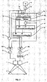
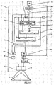
- Fig. 1 shows a schematic view of a configuration of prior art, a traditional double stacking comprising essentially identical projectors, a first projector 1 and a second projector 2, each projecting an image onto a projection surface 3 and each having a decoding gamma function corresponding to the encoding gamma of an image generator 4, which is outputting a source image signal comprising an array of pixel values.
- the connecting lines in the schematic view illustrate image signal paths.
- the output of the image generator is supplied to the input of the first projector 1 and to the input of a warping circuit 5.
- the output of the warping circuit 5 is supplied to the input of the second projector 2.
- the warping circuit 5 performs a geometrical correction of the image projected by the second projector 2 to align it with the image projected by projector 1 and compensate for mechanical misalignment between projected images. Repeated re-calibrations may be needed to compensate for movements in mechanical and optical parts due to thermal variations etc.
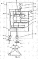
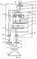
- Fig. 2 shows a schematic view of a first embodiment of the invention.
- an image splitting function comprising a gamma decoding circuit 6, a first gamma encoding circuit 7, a second gamma encoding circuit 8, an image buffer 9, a lightening image limiter 10, a first image subtraction circuit 11, a darkening image limiter 12, a second image subtraction circuit 13, a first constrained smoothing filter 14, a second constrained smoothing filter 15, an image inversion circuit, a first image division circuit 101 and a second image division circuit 102, all connected as shown in the figure.
- the gamma decoding circuit 6 is matched to the encoding gamma of the image generator 4, the first gamma encoding circuit 7 is matched to the decoding gamma of the second projector 2 and the second gamma encoding circuit 8 is matched to the decoding gamma of the first projector 1.
- the image buffer 9 stores a threshold image T which holds for each pixel value a representation of the fraction of illumination intensity which the first projector 1 is contributing to the corresponding position on the projection surface 3 when both projectors are supplied uniform, maximum intensity images to their inputs. Since in this embodiment the first projector 1 and the second projector 2 are essentially identical, the first projector 1 contributes half the illumination intensity in all positions, and all pixel values in T are 0.5. In an alternative configuration of this embodiment, the projectors are not identical but have different spatial distribution of their maximum illumination intensities; hence T is an image having pixels with varying values between 0 and 1.
- the content T of the image buffer 9 and the output of the gamma decoding circuit 6 are supplied to the lightening limiter 10.
- the lightening image limiter 10 calculates an image that in every pixel position is the higher of the two inputs and it outputs the result to the first image subtraction circuit 11, which subtracts T and supplies the result to a lower bound image input LB of the constrained smoothing filter 14.
- the pixel values of this image represents the amount of intensity that the first projector 1 is not capable of reproducing alone, hence the minimum intensity the second projector 2 should contribute in the corresponding pixel position.
- the content T of the image buffer 9 is supplied to the image inversion circuit 16 and the output of the image inversion circuit 16 is supplied to the darkening image limiter 12. Further, the output of the gamma decoding circuit 6 is supplied to the darkening image limiter 12.
- the darkening image limiter 12 calculates an image that in every pixel position is the lower of the two inputs and outputs the result to an upper bound image input UB of the constrained smoothing filter 14. This image represents the maximum intensity the second projector 2 should contribute, i.e. the desired resulting pixel intensities limited by the maximum intensity the second projector is able to contribute in the corresponding pixel position.
- the first constrained smoothing filter 14 calculates a generally smooth, blurry output image with only few high frequency components and where the output image is essentially constrained in any pixel position to have a pixel value in the range from the corresponding pixel value in the lower bound image LB and the corresponding pixel value in the upper bound image.
- Fig. 3 shows a process flowchart of an exemplary configuration of the constrained smoothing filter 14.
- the constrained smoothing filter 14 performs a greyscale dilation operation with a dilation radius r1 on the lower bound input image LB followed by a blur operation with a blur radius r1' smaller than or equal to r1 on the result of the greyscale dilation operation, followed by a darkening image limiting operation with the upper bound input image UB on the result of the blur operation, limiting pixel values in the result of the blur operation to be smaller than or equal to the corresponding pixel values in the upper bound input image UB and the result of the darkening image limiting operation is the output of the first constrained smoothing filter.
- the darkening image limiting operation may be omitted and the result of the blur operation may be the output of the first constrained smoothing filter.
- the dilation radius r1 may be 4 pixels and the blur radius r1' may be equal to r1.
- the dilation radius r1 may be 1/300 th of the width of the lower bound input image LB and the blur radius r1' may be equal to r1.
- the blur operation may be a Gaussian blur operation which may have a standard deviation of 1/3 * r1' or the blur operation may be a mean filtering operation.
- the first constrained smoothing filter 14 may comprise a spline based or membrane based envelope filter or a glow effect filter.
- the output of the first constrained smoothing filter 14 is supplied to a lower bound input of a second constrained smoothing filter 15 and the output of the image inversion circuit 16 is supplied to an upper bound input of the second constrained smoothing filter 15.
- the second constrained smoothing filter 15 may perform an operation similar to that of the first constrained smoothing filter 14 with a dilation radius r2 and a blur radius r2'.
- the dilation radius r2 may be 2 pixels and the blur radius r2' may be equal to r2.
- the dilation radius r2 may be 1/600 th of the width of the lower bound input image of the second constrained smoothing filter 15 and the blur radius r2' may be equal to r2.
- the second constrained smoothing filter 15 may be substituted by a blur filter.
- the output of the gamma decoding circuit 6 and the output of the second constrained smoothing filter 15 are supplied to an image subtraction circuit 13 which calculates an image by subtracting the output of the second constrained smoothing filter 15 from the output of the gamma decoding circuit 6.
- the result of the subtraction is supplied to a first input of the first image division circuit 101.
- the output image T from the image buffer 9 is supplied to a second input of the first image division circuit 101.
- the first image division circuit 101 divides the first input by the second input and the result of the division is supplied to the input of the second gamma encoding circuit 8.
- the first image division circuit 101 scales pixel values in the output image of the second image subtraction circuit 13, which will be in the range from 0 to the corresponding pixel values of T, by dividing with the pixel values in T, so the resulting output pixel values are scaled to be in the range 0 to 1.
- the output image of the second constrained smoothing filter 15 is further supplied to a first input of the second image division circuit 102 and the output of the image inversion circuit 16 is supplied to a second input of the second image division circuit 102.
- the second image division circuit 102 divides the first input by the second input and the result of the division is supplied to the input of the first gamma encoding circuit 7.
- the second image division circuit 102 scales pixel values in the output image of the second constrained smoothing filter 15, which will be in the range from 0 to the inverse of the corresponding pixel values of T, by dividing with the inverse of the pixel values in T, so the resulting output pixel values are scaled to be in the range 0 to 1.
- the output of the first gamma encoding circuit 7 is supplied to the input of the warping circuit 5 and the output of the warping circuit 5 is supplied to the input of the second projector 2.
- the output of the second gamma encoding circuit 8 is supplied to the input of the first projector 1.
- the darkening image limiter 12 may be omitted and a uniform, maximum intensity image may be supplied to the upper bound input of the first constrained smoothing filter 14.
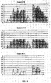
- Fig. 4 shows graphs of values in an example section of a row of pixels at different stages of the processing
- the first graph in Fig. 4 shows the output of the gamma decoding circuit 6
- the second graph shows the output of the darkening limiter 12
- the third graph shows the output of the first image subtraction circuit 11.
- Fig. 5 shows three graphs of values in the example section of a row of pixels at different stages of an operation of the constrained smoothing filter 14 with a dilation radius r1 of 3 pixels and a blur radius r1' essentially equal to r1.
- the result of the dilation operation is indicated as a black line with the lower bound input indicated in dark gray and the upper bound input indicated in light gray.
- the second graph shows in a similar manner the result of the blur operation and the third graph shows the result of the darkening operation.
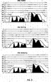
- Fig. 6 shows 3 example graphs of the values in a row of pixels
- the second graph shows the output of the image subtraction circuit 13
- the third graph shows summed values of the output of the second constrained smoothing filter 15 and the image subtraction circuit 13, which summed values, as noted above, translate directly to the resulting illumination intensity in the corresponding row of pixels on the projection surface 3 when alignment of the projected images is essentially perfect, because the operations are performed in a gamma of unity.
- the amount of high spatial frequencies in the output of the second constrained smoothing filter 15 is significantly less than in the output image of the gamma decoding circuit 6, resulting in a generally smoother, blurred image being projected by the second projector 2 than in a traditional double stacking configuration.
- a first advantage of the invention is that the smoother image of the second projector 2 reduces the visible artefacts introduced by a smaller misalignment of the projected images. In many cases, a misalignment of a full pixel or more is not noticeable, which in a traditional double stacking configuration would have introduced highly visible artefacts.
- the output of the second constrained smoothing filter 15 is not completely eliminated high frequency components.
- the upper bound and lower bound inputs to the first constrained smoothing filter 14 get so close, so it may not always be possible to create a smooth "curve" (or rather: surface) between them, and these areas of the projected image will be the most sensitive to misalignment.
- Setting r2 to a value higher than 0 will enforce a smoothing also in these areas, reducing spatial frequency components further and increase the misalignment tolerance.
- Fig. 7 is equivalent to fig. 6 , except that the dilation radius r2 is 2 pixels here and the blur radius r2' is essentially equal to r2.
- the dilation radius r1 is still 3 pixels and the blur radius r1' is still essentially equal to r1.
- the faint halo artefact is visible in the summed graph at the bottom just to the left of the highest peak. Fortunately, these artefacts may be unrecognizable for the Human Visual System in a projected image due to lateral inhibition in the neural response system on the retina (lateral masking), when r2 is below a limit determined by the overall projection system on-screen contrast, hence theoretical "perfect reconstruction" is not necessarily needed.
- Determining a good value for r2 for a given type of projection system may be performed by having a critical group of observers located in the front rows look at a test pattern containing maximum contrast edges and switch between random values of r2 and ask the group members to rate the images in terms of edge sharpness and then selecting the value of r2 where nobody notices the reduction of edge sharpness. It is noted that the reason for selecting the second constrained smoothing filter 15 also for the second filtering pass, as opposed to for example selecting a standard lowpass filter, is that this configuration preserves illumination intensity in small areas of highlights like reflections in water or leafs, which may be important visual clues that are not subject to suppression by lateral inhibition.
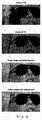
- Fig. 8 shows printed images of an output of the second constrained smoothing filter 15 together with the output of the image subtraction circuit 13 and a simulation of the resulting projected overlaid image calculated by adding the output of the second constrained smoothing filter 15 and the output of the image subtraction circuit 13. (The images have here been applied a gamma so they are watchable on print).
- Fig. 9 shows similar simulations of an enlarged section of an image projected with a 2 pixel misalignment.
- the upper image is a simulation of a projection with traditional double stacking and the lower image is a simulation of a projection with the first embodiment of the invention.
- a second advantage of the invention is that the output image of the second constrained smoothing filter 15 will generally not be watchable and not hold enough detail information to be manipulated into a watchable image without additional information being supplied, meaning, that in copy-protected projection systems, where signal paths and image storages are subject to encryption and physical anti-tampering requirements, the whole signal path from the output of the second constrained smoothing filter 15 including the warping circuit 5 and the second projector 2 may not need to be encrypted or physically secured.
- Fig. 10 shows an example of including the first embodiment in a digital cinema server.
- An anti-tampering protective housing 18 encompasses the indicated components.
- the output of the second gamma encoding circuit 8 is supplied to an encryption circuit 17 and the first projector 1 is a digital cinema projector capable of decrypting the input image signal.
- Fig. 11 shows an example of including the first embodiment in a digital cinema projector.
- the image generator 4 may be a digital cinema server outputting an encrypted image signal, a decryption circuit 19 decrypts the signal and the anti-tampering housing 18 encompasses the indicated components.
- FIG. 12 shows an example of the first embodiment included in a stand-alone unit with an image decryption circuit 18 decrypting the encrypted output of the image generator 4 which may be a digital cinema server and an image encryption circuit 17 encrypting the image signal and outputting the encrypted signal to a digital cinema server capable of decrypting the image signal and the anti-tampering housing encompassing the indicated components.
- the first gamma encoding circuit 7, the warping circuit 5 and the second projector 2 are outside the anti-tampering housing and process unencrypted signals, making the practical implementation relatively uncomplicated.
- a resampling circuit may be included, which resamples the output image from the first gamma encoding circuit 7 to a lower spatial resolution and supplies the resulting resampled image to the warping circuit 5 and where the warping circuit and the second projector 2 have lower spatial resolution than the first projector 1. Since the output of the first gamma encoding circuit 7 contains little high frequency components, this may have only little or no effect on the resulting image quality.
- a third advantage of the invention is that upgrade costs may be reduced and investments in existing equipment protected, for example in a theatre with a single 2K projector wishing to upgrade to 4K and increased brightness.
- the relaxed requirements to the second projector 2 opens up possibilities for asymmetric configurations where the second projector 2 may be a completely different projection system than the first projector 1, having limitations that would not make it useful for traditional double stacking but are less significant in a configuration of the first embodiment, like lower resolution, slightly visible blending edges or brightness differences of a tiled system, not supporting encryption etc., but having other relevant advantages, such as good black level, being already installed or being optimised to serve specialized applications when not used as part of the first embodiment, such as conference presentations, planetarium star field projection etc.
- an image erosion circuit is inserted between the output of the first constrained smoothing filter 14 and the lower bound input of the second constrained smoothing filter 15, where said image erosion circuit performs a greyscale erosion operation on the image signal received from the first constrained smoothing circuit 14.
- the radius R3 of the greyscale erosion operation may be 0.5 pixel or 1 pixel.
- a colour correction circuit is inserted between the output of the first image subtraction circuit 11 and the lower bound input of the first constrained smoothing filter 14.
- Said colour correction circuit is further connected to the output of the gamma decoding circuit 6 and it adds to the pixel values in the image received from the first image subtraction circuit 11 in a way so that the pixels in the output to the first constrained smoothing filter 14 have essentially the same hue as the corresponding pixels in the image signal received from the gamma decoding circuit 6.
- K Max(R11/R6, G11/G6, B11/B6)
- the output signal from the first gamma encoding circuit 7 or from the resampling circuit is recorded on a first medium and the output of the second gamma encoding circuit 8 is encrypted and recorded on a second medium, and the first medium and the second medium are played back synchronously with the output of the first recording medium being supplied to the warping circuit 5 which is calibrated for alignment of the images and supplies the warped output to the second projector 2 and the output of the second medium being supplied to projector 1.
- a fourth advantage of the invention is that it may reduce banding artefacts introduced by a traditional double stacking configuration, because it may have higher dynamic contrast resolution compared to that of a traditional double stacking system, since more different resulting intensities on said projection surface 3 is possible.
- the resulting overlaid image on the projection surface 3 may have discrete intensity steps exceeding the Just Noticeable Differences, which may result in visible banding.
- a fifth advantage of the invention is that an automatic re-alignment system based on a digital image capturing system taking pictures of resulting superimposed image projected on the projection surface 3 may separate a captured image into components originating from each projector and perform recalibration of the warping circuit without the need for iterations over a sequence of frames in a public presentation or using special iterating training sequences.
- a high frequency filtering of a captured image may create an image that is related only to the image being projected by the first projector 1 making it possible to do feature matching or tracking, identify a first set of misalignment vectors from the captured image with respect to the input image to the first projector 1 and warp the captured image so it is aligned with the first projector 1, and then subtract a gamma decoded version of the image being input to the first projector 1 from a gamma corrected and gain-corrected version of the captured image, resulting in an image that is related only to the image being projected by the second projector 2, so feature matching or tracking is possible and a second set of misalignment vectors between the captured image and the image being projected by the second projector 2 can be calculated, and from the first and second set of misalignment vectors calculate a third set of misalignment vectors, which is the misalignment vectors between the image being projected by the first projector 1 and the image being projected by the second projector 2 and from the third set of
- a single alignment image may be constructed which in one colour plane contains a geometric pattern, for example a grid, which has only pixel values above the values in the threshold image T and where another colour plane contains the same geometric pattern but with pixel values below the values in the threshold image T, thus for each pixel position it is possible to obtain relative misalignment vectors between the projectors and perform a re-calibration of the warping circuit 5.
- a geometric pattern for example a grid
- the first embodiment may be switchable to a single projector mode, in which one of the projectors is simply being supplied the source image.
- This single projector mode may act as fall-back operation in case of a projector failure and may be activated automatically by a detection system capable of detecting a projector failure, where the detection circuit may be an integrated part of the projector or where the detection circuit may be based on a digital image capture system taking pictures of the resulting superimposed image being projected on the projection surface 3, resulting in a degree of redundancy, where, for example in the case that a lamp blows, the system will continue to project correct images albeit with less brightness.
- Fig. 18 shows yet an alternative configuration of the first embodiment, supporting an especially advantageous re-alignment procedure, where an image buffer 103 holding an alignment pattern, an image addition circuit 104 and a darkening limiter 105 are added.
- the output of the image buffer 103 is supplied to one input of the image addition circuit 104 and the output of the constrained smoothing filter 15 is supplied to another input the image addition circuit 104, and the output of the image addition circuit 104 is supplied to one input of the darkening limiter 105 and the output of the gamma correction circuit 6 is supplied to another input of the darkening limiter 105 and the output of the darkening limiter is supplied to one input of the image division circuit 102 and to one input of the image subtraction circuit 13, as shown in the figure.
- the output of the image buffer 103 may be switchable between a black picture and the alignment pattern, so the alignment pattern can effectively be switched off, when alignment detection is not requested.
- the effects of these added circuit elements on the projected images are that the image projected by projector 2 will be added a constrained alignment pattern, which is the output of the image buffer 103 being constrained, so that the result of the addition in each pixel position is still equal to or lower than the intensities of the corresponding pixel values in the source image, and the image projected by projector 1 will be subtracted the constrained alignment image, so when the two images are superimposed on the projection surface 3 with perfect alignment, the alignment pattern will be cancelled out and become invisible, so only the source image is visible.
- the alignment pattern becomes visible as pattern sections of lower and higher intensities than the surrounding pixels.
- the position of lower and higher intensities indicates in which direction the misalignment is oriented. For example, if a section of an alignment pattern is visible as lighter pixel values compared to the surroundings, i.e. a lighter pattern imprint, and the same section of the alignment pattern is visible as darker pixel values compared to the surroundings, i.e. a darker pattern imprint, and the dark imprint is located to the right and below the light imprint, this indicates that projector 1 is displaced to the right and towards the lower edge relative to the position in which perfect alignment occurs.
- the alignment pattern may be designed, so it is not very noticeable to a general audience, though still useful for a projectionist, for example by comprising small graphic elements with regular spacing.
- the alignment pattern may be a grid, a mesh or any regular or irregular pattern of elements which may be dots, cross hairs or other graphic elements and it may contain barcodes, semacodes or other identifiers.
- Fig. 19 shows example signals of the configuration of fig. 18 , where the first image is the output the darkening limiter 105 with the added alignment pattern visible, the second image is the output of image subtraction circuit 13 with the subtracted alignment pattern visible, the third image is the resulting superimposed image on the projection surface 3 with perfect alignment and the fourth image is an example of a resulting superimposed image on the projection surface 3 when misalignment is present.
- a first colour plane may be projected with an alignment pattern by the configuration shown in fig. 18 and the other colour planes may be projected without alignment patterns.
- the mechanical misalignment of projectors and projection optics will affect the colour planes essentially identical, so the misalignment information observed from the first colour plane can be used to detect and correct the misalignment of all colour planes.
- a camera may record the image on the projection surface 3 and an image processing system may detect and correct misalignment.
- the image processing system may perform feature matching or feature tracking, for example scale invariant feature tracking, to perform recognition of the alignment pattern or alignment pattern sections.
- the camera may have a long exposure time, so that several different projected images, for example subsequent frames of a moving picture, are integrated in the image capturing element over one exposure, thereby blurring all non-static picture elements, but preserving the static alignment pattern for easier recognition of alignment pattern or alignment pattern sections.
- the alignment pattern or alignment pattern sections may be separated from the integrated and blurred image by a high pass filtering.
- a sequence of images to be projected may be pre-processed, to increase the blurring of other elements than the alignment pattern when later integrated in the camera's image capturing element, for example a slow, cyclic motion may be introduced to static scenes of a sequence of a moving picture, or one of the colour planes, for example the blue colour plane, may be blurred in one or more or all of the frames of the moving picture.
- a slow, cyclic motion may be introduced to static scenes of a sequence of a moving picture, or one of the colour planes, for example the blue colour plane, may be blurred in one or more or all of the frames of the moving picture.
- an additional colour correction circuit may be comprised, which adds to the pixel values in the colour channels of the outputs of the first constrained smoothing filters 14 in a way so that the hue of the pixels in the output of the first constrained smoothing filters 14 are essentially identical to the hues of the corresponding pixels in the output of the gamma decoding circuit 6.
- the additional colour correction circuit may perform an operation, where it for each pixel calculates a fraction value, which is the pixel value of the output of the first constrained smoothing filter 14 divided by the corresponding pixel value of the output of the gamma decoding circuit 6, then the additional colour correction circuit identifies the greatest of the fraction values for each of the colour planes, i.e. for each of the multiple configurations of the first embodiments, and for each of the colour planes, a new pixel value is calculated by multiplying the output of the gamma decoding circuit 6 with the fraction value for the colour plane, and the resulting pixel value is supplied to the input of the second constrained smoothing filter 15.
- This colour projection system is that the hues projected from the first projector 1 and from the second projector 2 will for each pixel be essentially identical, which may further decrease visible artefacts resulting from misalignment.
- a 3D system is comprising two image processing circuits according to the first embodiment, a first image processing circuit according to the first embodiment being supplied a left perspective image of a 3D image and a second image processing circuit according to the first embodiment being supplied a left perspective image of said 3D image and three projectors, two stationary polarization filters, a temporal varying polarization unit, such as the RealD ZScreen or the RealD XL polarizing beam splitter arrangement with ZScreens, a non-depolarizing projection screen and eyewear with polarizers.
- a first projector is supplied the output of the second gamma encoding circuit 8 of said first image processing system and has a first polarization filter inserted in the optical path between the light source of said first projector and said projection screen
- a second projector is supplied the output of the second gamma encoding circuit 8 of said second image processing system and has a second polarization filter inserted in the optical path between the light source of said second projector and said projection screen, said first polarization filter and said second polarization filter having essentially orthogonal polarization directions or opposite circular polarization direction
- a third projector is projecting alternately the output of the first gamma encoding circuit or the resampling circuit of said first image processing system and the output of the first gamma encoding circuit or the resampling circuit of said second image processing system.
- two separate projection systems one for a left eye image and one for a right eye image, use each one projector for the high frequency image and share a time multiplexed project
- the third projector projects alternately the overlay images of the left and right perspective images that have low amounts of high frequency components, therefore the requirements to the performance of this projector in terms of resolution are relaxed, again allowing to optimize the projector for brightness on the cost of some resolution or image sharpness, for example utilizing a polarizing beam splitter with image combiner, such as for example the RealD XL adapter, which essentially doubles the light output of the projector, but at the cost of limiting the maximum obtainable resolution in practical implementations.
- a polarizing beam splitter with image combiner such as for example the RealD XL adapter
- a 3D projection system comprising three projectors with a 7KW Xenon lamp each could result in the same brightness as that of a system comprising four projectors with 7KW lamps each, which could be adequate for illuminating 3D giant screens.
- Such a system could rival exisiting filmbased 3D projection systems for giant screens in both image resolution, brightness, image stability, contrast, dynamic range and frame rate.
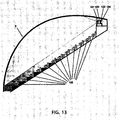
- Fig. 13 shows an immersive, stereoscopic projection configuration with a total of four overlaid projectors, a first left projector 121, a second left projector 122, a first right projector 123 and a second right projector 124, where the first left projector 121 and the second left projector 122 are parts of a configuration according to the first embodiment and are projecting a left view of a stereoscopic image and where the first right projector 123 and the second right projector 124 are parts of a configuration according to the first embodiment and are projecting a right view in an immersive giant screen theatre where the projection surface 3 may be a domed screen or a big flat screen located close to the audience so a large portion of the field of view of the members of the audience located in the theatre seats 125 is filled with image and where the audience members are wearing stereoscopic eyewear.
- the projectors may be located off-axis close to the edge of the domed screen and may comprise wide angle or fisheye projection optics.
- the projection optics may be constructed so that pixel density is higher in an area, a "sweet spot", in front of the audience, as is well known in the art of immersive projection.
- the projection optics may further comprise anamorphic adaptors, which stretch the image in the vertical direction to fill a larger area of the dome.
- Additional warping circuits may be comprised, which performs a geometrical correction of the left eye source image and the right eye source image.
- the warping circuits may operate individually on each of the colour planes of the source images so they can be calibrated to further compensate for chromatic aberration in the projection optics.
- a playback system may be included, capable of synchronously reproducing previously recorded outputs from an image splitting circuit according to the first embodiment stored on at least one storage medium and supplying the reproduced outputs to the projectors.
- the storage medium may comprise at least one hard disk containing a first set of assets comprising a first signal for the first left projector 1, where the first signal is the recorded output of the second gamma encoding circuit 8 when the left source image was supplied to the input of the gamma decoding circuit 6 and a second signal for the first right projector 1, where the second signal is the recorded output of the second gamma encoding circuit 8 when the right source image was supplied to the input of the gamma decoding circuit 6, and further containing a second set of assets comprising a third signal for the second left projector, where the third signal is the recorded output of the first gamma encoding circuit 7 when the left source image was supplied to the input of the gamma decoding circuit 6, and a fourth signal for the second right projector, where the fourth signal is the recorded output of the first gamma encoding circuit 7 when the right source image was supplied to the input of the gamma decoding circuit 6.
- the first set of assets may be stored on the hard disk in the format of a stereoscopic Digital Cinema Package and the second set of assets may be stored on the hard disk in the format of a stereoscopic Digital Cinema Package.
- the first set of assets may be stored in an encrypted form and the playback system may be able to supply an encrypted signal to the input of the first left projector and an encrypted signal to the input of the first right projector.
- a first warping circuit may be comprised located in the signal path from the playback system to the second left projector and a second warping circuit may be comprised located in the signal path from the playback system and the second right projector where the first warping circuit and the second warping circuit are calibrated for alignment of the images.
- the projectors in the configuration of fig. 12 may use spectral separation for separating the left and right eye views, where members of the audience wear eyewear with dichroic spectral separation filters and where the projectors comprise dichroic spectral separation filters.
- the separation filters of the first left projector 121 and the second left projector 122 may be essentially identical and the left eye separation filter in the eyewear may be matched to the separation filters of the first left projector 121 and the second left projector 122 and the separation filters of the first right projector 123 and the second right projector 124 may be essentially identical and the right eye separation filter in the eyewear may be matched to the separation filters of the first right projector 123 and the second right projector 124.
- Spectral separation stereoscopic projection has the advantage of not requiring a special projection surface which is attractive in many immersive cinema applications, and it has very good image quality and stereoscopic reproduction in a central part of the field of vision, but it has the disadvantage of introducing artefacts outside of the central part of the field of vision, because the filters in the eyewear differ from their nominal performance for incident light with angles not normal (perpendicular) to the filters, a phenomenon which is inherent in the nature of dichroic filters. For these reasons, an improved system for spectral separation stereoscopic projection shall be proposed below.
- Fig. 14 shows an example of prior art.
- a lamp 20 in a first projector emits light into an integrating rod 21 which creates a uniform illumination at the output end.
- a second projector (not shown) is configured equivalently but with a second projector filter (not shown), which is mutually exclusive to the first projector filter 23.
- the first projector filter 23 and the second projector filter have mutually exclusive pass bands and in between there are spectral ranges called guard bands where both the first projector filter 23 and the second projector filter have little transmittance.
- the left eye separation filter in the eyewear may be a dichroic filter having a set of pass bands encompassing the pass bands in the first projector filter 23 and the right eye separation filter in the eyewear may be a dichroic filter having a set of pass bands encompassing the pass bands in the second projector filter.
- the separation filters in the eyewear may be slightly curved to partly compensate for the non-normal (non-perpendicular) angle of incident light from pixels in the peripheral areas of the image as observed by a member of the audience positioned with her head directed essentially straight forward with her nose towards the screen, because light with a non-orthogonal angle of incidence travels a longer distance between the dichroic layers of the separation filters, hence is subject to a filtering where the pass bands have been spectrally shifted compared to the filtering of light from pixels in the middle area of the image with essentially normal (perpendicular) angle of incidence, which would otherwise cause the match with the projector filters to be reduced beyond the tolerances provided by the guard bands in the projector filters, giving rise to colour artefacts and artefacts of crosstalk between left and right projection systems ("ghosting") in the peripheral parts of the image.
- non-normal angle of incident light from pixels in the peripheral areas of the image as observed by a member of the audience positioned with her head directed essentially straight forward with her nose
- Fig. 15 shows an alternative configuration of the system in fig. 14 where the colour and ghosting artefacts in peripheral parts of the image are compensated by modifying the first projector filter 23 and the second projector filter so the spectrally filtered light at the exit pupils of the projectors becomes wavelength shifted as a function of the angle of emission.
- the first projector filter 23 and the second projector filter are curved with essentially identical curves, so that light focused on pixels in the peripheral parts of the light modulator chips traverse longer distances between the dichroic layers than light focused on the central parts of the light modulator chips, hence light focused on the peripheral parts of the light modulator chips is wavelength shifted with respect to light focused on the central parts of the light modulator chips and therefore light emitted from pixels in the peripheral parts of the projected image is wavelength shifted with respect to light emitted from pixels in the central parts of the projected image, resulting in a better match of the filtering by the projector filters and the filtering of the eye filters for pixels in the peripheral parts of the image, and in more pixels in the peripheral parts of the image being filtered by the eye filters so that the pass bands of the eye filters encompass the pass bands of the projector filters when observed by a member of the audience in a target observation position.
- the curve of the first projector filter 23 and the second projector filter may be spherical with radii equal to the width of the aperture of the integrating rod 21.
- An electronic colour correction is normally applied to the source image to compensate for a slight hue changes as perceived by the Human Visual System in the filters, which cannot be avoided completely for manufacturing reasons.
- This colour correction is normally spatially uniform over the image area. In the case of using curved filter, this colour correction may instead be spatially nonuniform, so as to achieve projected images that are perceived as uniform in hue to the Human Visual System.
- dichroic filters with varying thickness of the dielectric layers may be comprised.
- Fig. 16 shows an alternative configuration, where the first projector filter 23 and the second projector filter may each have a flat area in a central region and only have a curved shape in the peripheral areas of the image where the tolerance by above the mentioned other means of reducing the artefacts in peripheral areas of the image do not suffice.
- the optimal curve of the projector filters is a function of the distance from the member of the audience to the screen, the curve of the eye filters, the focal length of the relay lenses of the illumination system of the projectors, subjective aesthetic preferences and other factors. A compromise between the "tunnel vision" and “gazing through a pair of holes" may be desirable.
- Fig. 17 shows yet an alternative configuration equivalent to the configuration of fig. 14 , but where a first curved notch filter 27 resting on a first glass substrate 26 is added located in front of the first projector filter 23 in the left projector and a second curved notch filter resting on a second glass substrate are added correspondingly in the second projector, and where the notch filters have notches essentially matching the guard bands, so the width of the guard bands are being widened as a function of the emission angle of light exiting the exit pupils of the projectors, hence reducing artefacts in the peripheral field of vision and eliminating ghosting artefacts in the central field of vision in the case where the observer turns her head to a large angle that may occur in the configurations according to figs 14, 15 and 16 , although at the cost of reducing the brightness in the peripheral parts of the projected images.
- the notch filters may have a flat area in a central part of the image.
- the invention is additionally or alternatively characterized by an image processing circuit separating an input image into a first image, being the input image clamped to a threshold, and a second image, being the remainder.
- the second image is smoothened by moving fractions of pixel values from the first image to the darker areas around edges, reducing the content of high-frequency components in the second image, keeping the sum of the two images identical to the input image. Scaling and gamma corrections are performed at the input and outputs, ensuring that actual luminance superposition applies to the calculations. With perfect alignment, the projected overlaid image will correspond exactly to the input image, whilst the second image will have less high frequency components than the first image.
- a first advantage is that the system significantly reduces the perceived artefacts arising from minor misalignment, since the human visual system is less sensitive to errors in low frequency components than in high frequencies. Only where there are edges having a contrast higher than one projector can "drive" alone, the second image will contain high frequency components. However, the human visual system exhibits a lower spatial resolution close to edges of contrasts of 150:1 and above, due to the so called spatial masking effect, so misalignment artefacts at high contrast edges will also be reduced in visibility. A low-pass filtering of the second image, moderate enough to be invisible due to the masking effect of the first image's high frequency components, may help masking misalignment artefacts at high contrast edges further.
- a second advantage is that a camera-based automatic alignment system can periodically perform realignment throughout a film projection, based on the images in the film, with no need for special calibration sequence runs. Because the projectors do not project identical images, it is possible to separate the first and the second image from the recorded on-screen image, and from those calculate misalignment information, which in turn may be used for electronic re-alignment by geometric correction (warping).
- a third advantage is that a single-projector 2K system can be upgraded to increased brightness and 4K resolution, by adding a 4K projector. Since an invisible moderate low pass filtering of the second image is possible, it results in that it is possible to use a lower resolution projector for the second image, maintaining the appearance of the full high resolution of the first projector (only brighter).
- a fourth advantage is that the resulting luminance resolution of the system is higher than that of a single projector, which could be of significance to high dynamic range projection systems.
Landscapes
- Engineering & Computer Science (AREA)
- Multimedia (AREA)
- Signal Processing (AREA)
- Physics & Mathematics (AREA)
- General Physics & Mathematics (AREA)
- Theoretical Computer Science (AREA)
- Projection Apparatus (AREA)
- Transforming Electric Information Into Light Information (AREA)
- Controls And Circuits For Display Device (AREA)
- Control Of Indicators Other Than Cathode Ray Tubes (AREA)
- Image Processing (AREA)
Claims (10)
- Procédé de projection d'image pour un système comprenant un premier projecteur d'image (1) et un second projecteur d'image (2), où les premier et second projecteurs d'image projettent des images de recouvrement sur une surface de projection (3), résultant en une image superposée, caractérisé par :i) la limitation seuil et le filtrage de lissage sous contrainte d'une image d'entrée, source (4) par :a) le découpage, la séparation, de l'image d'entrée, source, en une première image, ramenée à un seuil (T), et une seconde image, qui est le reste ;b) le lissage de la seconde image pour réduire un contenu de composantes haute fréquence ;c) le maintien de la somme des deux images identique à l'image d'entrée, source ;ii) moyennant quoi, lorsque le premier projecteur (1) projette la première image de projecteur, et le second projecteur (2) projette la seconde image de projecteur, l'image de recouvrement formée sur la surface de projection (3) correspond essentiellement à l'image d'entrée (4), et où la quantité de hautes fréquences spatiales est inférieure dans la seconde image de projecteur que dans la première image de projecteur.
- Procédé selon la revendication 1, dans lequel la seconde image est lissée en déplaçant des fractions de valeurs de pixel de la première image à des zones plus sombres autour des contours.
- Procédé selon la revendication 1 ou la revendication 2, caractérisé en outre par :i) le calcul à partir de l' image source (4) et de l'image seuil (T) d'une image qui dans chaque position de pixel est la plus élevée de l'image source et de l'image seuil et la soustraction de l'image seuil de ladite image calculée pour produire une image liée inférieure (LB) ; les valeurs de pixel de cette image liée inférieure représentant la quantité d'intensité que le premier projecteur (1) n'est pas capable de reproduire seul, d'où l'intensité minimale à laquelle le second projecteur (2) devrait contribuer dans la position de pixel correspondante ;ii) l'inversion de l'image seuil (T) ;iii) le calcul à partir de l'image source (4) et de l'image seuil (T) inversée d'une image liée supérieure (UB) dans lequel chaque position de pixel est la moins élevée de l'image source et de l'image seuil inversée ; cette image liée supérieure représente l'intensité maximale à laquelle le second projecteur (2) devrait contribuer, c'est-à-dire les intensités de pixel résultant souhaitées limitées par l'intensité maximale à laquelle le second projecteur est capable de contribuer dans la position de pixel correspondante.
- Procédé selon la revendication 3, caractérisé en outre par la réalisation d'une opération de dilatation de l'échelle des gris avec un rayon de dilatation r1 sur l'image d'entrée liée inférieure (LB) suivie d'une opération de flou avec un rayon de flou r1' inférieur ou égal à r1 sur le résultat de l'opération de dilatation de l'échelle des gris.
- Procédé selon la revendication 3 ou la revendication 4, caractérisé en outre par le filtrage de l'image source (4) et de l'image seuil inversée pour produire une image de sortie floue généralement lisse avec uniquement quelques composantes haute fréquence ; moyennant quoi ladite image de sortie floue et lisse est essentiellement contrainte en toute position de pixel pour avoir une valeur de pixel dans la plage à partir de la valeur de pixel correspondante dans l'image liée inférieure (LB) et la valeur de pixel correspondante dans l'image liée supérieure (UB).
- Procédé selon l'une quelconque des revendications 2 à 5, caractérisé en outre par la réalisation de corrections gamma et de mise à l'échelle sur des images source (4) et des première et seconde images de projecteur (1, 2), garantissant que la superposition de luminance réelle s'applique à tout calcul ; moyennant quoi, avec un alignement parfait, l'image de recouvrement projetée (3) correspondra exactement à l'image d'entrée, tandis que la seconde image de projecteur (2) aura moins de composantes haute fréquence que la première image de projecteur (1).
- Procédé selon l'une quelconque des revendications 4 à 6, comprenant en outre :i) le calcul d'une image en soustrayant (13) l'image liée inférieure (LB) dilatée et floue de l'image source (4) ;ii) la division (101) de l'image calculée (13) par l'image seuil (9) pour produire la première image de projecteur (1) ;
et,iii) la division (102) de l'image liée inférieure (LB) dilatée et floue par l'image seuil inversée (T) pour produire la seconde image de projecteur (2). - Système de projection d'image comprenant deux projecteurs d'image, un premier projecteur (1) et un second projecteur (2), où ledit premier projecteur et ledit second projecteur projettent des images de recouvrement sur une surface de projection (3), résultant en une image superposée, caractérisé par un premier circuit de traitement d'image (10 à 16, 101 à 102) organisé et agencé pour réaliser le procédé de l'une quelconque des revendications 1 à 7, dans lequel la quantité de hautes fréquences spatiales est inférieure dans la seconde image de projecteur (2) que dans la première image de projecteur (1).
- Système selon la revendication 8, dans lequel le premier projecteur (1) et le second projecteur (2) ont chacun une fonction de décodage gamma correspondant à l'encodage gamma d'un générateur d'image (4), qui fournit en sortie un signal d'image source comprenant une matrice de valeurs de pixel caractérisé en ce qu'un circuit de traitement d'image (10) comprend un circuit de décodage gamma (6), un premier circuit d'encodage gamma (7), un second circuit d'encodage gamma (8), une mémoire tampon d'image (9), un limiteur d'image d'éclaircissement (10), un premier circuit de soustraction d'image (11), un limiteur d'image d'assombrissement facultatif (12), un circuit de soustraction d'image (13), un premier filtre de lissage sous contrainte (14), un second filtre de lissage sous contrainte facultatif (15), un circuit d'inversion d'image (16), un premier circuit de division d'image (101) et un second circuit de division d'image (102) ;
dans lequel le circuit de traitement d'image (10) est connecté et organisé de sorte que :i) le circuit de décodage gamma (6) soit associé à l'encodage gamma du générateur d'image (4), le premier circuit d'encodage gamma (7) soit associé au décodage gamma du second projecteur (2) et le second circuit d'encodage gamma (8) soit associé au décodage gamma du premier projecteur (1) ;ii) la mémoire tampon d'image (9) stocke une image seuil (T) qui maintient pour chaque valeur de pixel une représentation de la fraction d'intensité d'illumination à laquelle le premier projecteur (1) contribue à la position correspondante sur la surface de projection (3) lorsque les deux projecteurs fournissent des images d'intensité maximale uniforme à leurs entrées ;iii) l'image de sortie (T) de la mémoire tampon d'image (9) et la sortie du circuit de décodage gamma (6) soient fournies au limiteur d'éclaircissement (10), le limiteur d'image d'éclaircissement (10) calcule une image qui dans chaque position de pixel est la plus élevée des deux entrées et il fournit en sortie le résultat au premier circuit de soustraction d'image (11), qui soustrait T et fournit le résultat à une entrée d'image liée inférieure (LB) du filtre de lissage sous contrainte (14), les valeurs de pixel de cette image représentent la quantité d'intensité que le premier projecteur (1) n'est pas capable de reproduire seul, d'où l'intensité minimale à laquelle le second projecteur (2) devrait contribuer dans la position de pixel correspondante ; etiv) l'image de sortie (T) de la mémoire tampon d'image (9) soit fournie au circuit d'inversion d'image (16) et la sortie du circuit d'inversion d'image (16) soit fournie au limiteur d'image d'assombrissement (12), la sortie du circuit de décodage gamma (6) soit fournie au limiteur d'image d'assombrissement (12), le limiteur d'image d'assombrissement (12) calcule une image qui dans chaque position de pixel est la moins élevée des deux entrées et fournit en sortie le résultat à une entrée d'image liée supérieure (UB) du filtre de lissage sous contrainte (14), cette image représente l'intensité maximale à laquelle le second projecteur (2) devrait contribuer, c'est-à-dire les intensités de pixel résultant souhaitées limitées par l'intensité maximale à laquelle le second projecteur est capable de contribuer dans la position de pixel correspondante. - Système selon la revendication 9, dans lequel le circuit de traitement d'image (10) est en outre connecté et organisé de sorte que :i) la sortie du circuit de décodage gamma (6) et la sortie du second filtre de lissage sous contrainte (15) soient fournies au circuit de soustraction d'image (13) qui calcule une image en soustrayant la sortie du second filtre de lissage sous contrainte (15) de la sortie du circuit de décodage gamma (6), le résultat de la soustraction soit fourni à une première entrée du premier circuit de division d'image (101), l'image de sortie (T) de la mémoire tampon d'image (9) soit fournie à une seconde entrée du premier circuit de division d'image (101), le premier circuit de division d'image (101) divise la première entrée par la seconde entrée et le résultat de la division soit fourni à l'entrée du second circuit d'encodage gamma (8) ;ii) l'image de sortie du second filtre de lissage sous contrainte (15) soit en outre fournie à une première entrée du second circuit de division d'image (102) et la sortie du circuit d'inversion d'image (16) soit fournie à une seconde entrée du second circuit de division d'image (102), le second circuit de division d'image (102) divise la première entrée par la seconde entrée et le résultat de la division soit fourni à l'entrée du premier circuit d'encodage gamma (7).
Applications Claiming Priority (4)
| Application Number | Priority Date | Filing Date | Title |
|---|---|---|---|
| DKPA201000321 | 2010-04-18 | ||
| DKPA201000320 | 2010-04-18 | ||
| US35698010P | 2010-06-21 | 2010-06-21 | |
| EP11741133.0A EP2564374B1 (fr) | 2010-04-18 | 2011-04-18 | Projection à double superposition |
Related Parent Applications (2)
| Application Number | Title | Priority Date | Filing Date |
|---|---|---|---|
| EP11741133.0A Division EP2564374B1 (fr) | 2010-04-18 | 2011-04-18 | Projection à double superposition |
| EP11741133.0A Division-Into EP2564374B1 (fr) | 2010-04-18 | 2011-04-18 | Projection à double superposition |
Publications (3)
| Publication Number | Publication Date |
|---|---|
| EP2843618A2 EP2843618A2 (fr) | 2015-03-04 |
| EP2843618A3 EP2843618A3 (fr) | 2015-03-25 |
| EP2843618B1 true EP2843618B1 (fr) | 2016-08-31 |
Family
ID=44629914
Family Applications (2)
| Application Number | Title | Priority Date | Filing Date |
|---|---|---|---|
| EP11741133.0A Active EP2564374B1 (fr) | 2010-04-18 | 2011-04-18 | Projection à double superposition |
| EP14188609.3A Active EP2843618B1 (fr) | 2010-04-18 | 2011-04-18 | Double projection empilées |
Family Applications Before (1)
| Application Number | Title | Priority Date | Filing Date |
|---|---|---|---|
| EP11741133.0A Active EP2564374B1 (fr) | 2010-04-18 | 2011-04-18 | Projection à double superposition |
Country Status (7)
| Country | Link |
|---|---|
| US (1) | US8842222B2 (fr) |
| EP (2) | EP2564374B1 (fr) |
| JP (1) | JP5813751B2 (fr) |
| CN (1) | CN103026381B (fr) |
| CA (1) | CA2795392C (fr) |
| RU (1) | RU2562757C2 (fr) |
| WO (1) | WO2011134834A2 (fr) |
Families Citing this family (37)
| Publication number | Priority date | Publication date | Assignee | Title |
|---|---|---|---|---|
| US8842222B2 (en) | 2010-04-18 | 2014-09-23 | Imax Corporation | Double stacked projection |
| KR101872233B1 (ko) * | 2011-04-19 | 2018-06-29 | 돌비 레버러토리즈 라이쎈싱 코오포레이션 | 고휘도 투사형 디스플레이들 및 관련 방법들 |
| US20120320077A1 (en) * | 2011-06-17 | 2012-12-20 | Microsoft Corporation | Communicating status and expression |
| CA2842572C (fr) * | 2011-08-16 | 2020-10-13 | Imax Corporation | Decomposition et projection d'images hybrides |
| US10326968B2 (en) | 2011-10-20 | 2019-06-18 | Imax Corporation | Invisible or low perceptibility of image alignment in dual projection systems |
| US9503711B2 (en) | 2011-10-20 | 2016-11-22 | Imax Corporation | Reducing angular spread in digital image projection |
| KR101387097B1 (ko) | 2013-04-02 | 2014-04-29 | 유한회사 마스터이미지쓰리디아시아 | 삼중 광분할 방법과 이를 이용한 입체 영상장치 |
| KR20150037368A (ko) | 2013-09-30 | 2015-04-08 | 삼성전자주식회사 | 변조기 어레이, 이를 포함한 변조 장치 및 의료 영상 기기 |
| CN104657971B (zh) * | 2013-11-25 | 2018-10-12 | 联想(北京)有限公司 | 一种电子设备及其工作状态的控制方法、控制单元 |
| WO2015121542A1 (fr) * | 2014-02-13 | 2015-08-20 | Highlands Technologies Solutions | Procédé d'alignement perfectionné de deux moyens de projection |
| US9934714B2 (en) * | 2014-03-18 | 2018-04-03 | Nvidia Corporation | Superresolution display using cascaded panels |
| CA2917585C (fr) * | 2014-05-15 | 2016-09-27 | Mtt Innovation Incorporated | Optimisation de schemas d'actionnement pour systemes de projecteurs multiples |
| US20230027499A1 (en) * | 2014-05-15 | 2023-01-26 | Mtt Innovation Incorporated | Optimizing drive schemes for multiple projector systems |
| CN105488550B (zh) * | 2014-09-17 | 2018-05-08 | 北大方正集团有限公司 | 二维码设置方法及装置、透明物体 |
| JP6609098B2 (ja) * | 2014-10-30 | 2019-11-20 | キヤノン株式会社 | 表示制御装置、表示制御方法、及びコンピュータプログラム |
| US10080004B2 (en) * | 2014-11-06 | 2018-09-18 | Disney Enterprises, Inc. | Method and system for projector calibration |
| CN107409192B (zh) * | 2015-03-27 | 2021-04-16 | 索尼公司 | 图像显示设备及方法、信息处理方法以及计算机可读介质 |
| KR101702024B1 (ko) | 2015-04-06 | 2017-02-02 | 유한회사 마스터이미지쓰리디아시아 | 원격정렬형 입체영상장치 및 이를 이용한 입체영상상영방법 |
| GB2542764A (en) * | 2015-09-23 | 2017-04-05 | Pathxl Ltd | Image processing method and apparatus for normalisation and artefact correction |
| US10242427B2 (en) * | 2016-07-29 | 2019-03-26 | Massachusetts Institute Of Technology | Deviation magnification: revealing departures from ideal geometries |
| US10212414B2 (en) * | 2016-08-01 | 2019-02-19 | Microsoft Technology Licensing, Llc | Dynamic realignment of stereoscopic digital consent |
| US10531055B2 (en) | 2016-09-30 | 2020-01-07 | Dolby Laboratories Licensing Corporation | Beam combining for highlight projection |
| US10249060B2 (en) * | 2016-12-14 | 2019-04-02 | Caterpillar Inc. | Tool erosion detecting system using augmented reality |
| GB201701363D0 (en) * | 2017-01-27 | 2017-03-15 | Secr Defence | Apparatus and method for registering recorded images |
| WO2018163875A1 (fr) * | 2017-03-09 | 2018-09-13 | ソニー株式会社 | Dispositif et procédé de traitement d'image |
| WO2018180530A1 (fr) | 2017-03-28 | 2018-10-04 | ソニー株式会社 | Dispositif et procédé de traitement d'images |
| US10176551B2 (en) * | 2017-04-27 | 2019-01-08 | Apple Inc. | Configurable convolution engine for interleaved channel data |
| US11611728B2 (en) * | 2017-05-12 | 2023-03-21 | Mtt Innovation Incorporated | High brightness projection systems and methods |
| WO2019054179A1 (fr) * | 2017-09-12 | 2019-03-21 | ソニー株式会社 | Dispositif et procédé de traitement d'image |
| TWI682358B (zh) * | 2017-10-25 | 2020-01-11 | 宏芯科技股份有限公司 | 多維影像投射裝置及其多維影像校正方法 |
| WO2019126075A1 (fr) | 2017-12-22 | 2019-06-27 | Dolby Laboratories Licensing Corporation | Modélisation temporelle de modulateurs de phase dans une projection à modulation multiple |
| CN108600720B (zh) * | 2018-07-18 | 2024-02-20 | 中国电影器材有限责任公司 | 一种用于图像信号hdr投影的光源、装置、系统及方法 |
| CN108881872B (zh) * | 2018-07-24 | 2021-03-16 | 合肥合芯微电子科技有限公司 | 多维影像投射装置及其多维影像校正方法 |
| JP7147336B2 (ja) * | 2018-07-31 | 2022-10-05 | セイコーエプソン株式会社 | 投射方法及び投射システム |
| US11100830B2 (en) * | 2020-01-13 | 2021-08-24 | Nvidia Corporation | Method and apparatus for spatiotemporal enhancement of patch scanning displays |
| CN112153314B (zh) * | 2020-09-27 | 2023-04-07 | 中影环球(北京)科技有限公司 | 一种影院放映方法及系统 |
| CN114945086B (zh) * | 2022-06-07 | 2023-06-30 | 华中科技大学 | 一种基于曲面反射镜的单人正投球幕视域扩大方法及系统 |
Family Cites Families (62)
| Publication number | Priority date | Publication date | Assignee | Title |
|---|---|---|---|---|
| DE2827622A1 (de) | 1978-06-23 | 1980-01-03 | Heinz Arnold | Verfahren und vorrichtung zum herstellen von photografischen trickbildern |
| US4523226A (en) * | 1982-01-27 | 1985-06-11 | Stereographics Corporation | Stereoscopic television system |
| US4868773A (en) | 1985-03-15 | 1989-09-19 | Purdue Research Foundation | Digital filtering by threshold decomposition |
| US5070403A (en) | 1989-04-21 | 1991-12-03 | Sony Corporation | Video signal interpolation |
| GB2262854B (en) | 1991-12-24 | 1995-05-24 | Sony Broadcast & Communication | Image processing apparatus |
| US5488429A (en) | 1992-01-13 | 1996-01-30 | Mitsubishi Denki Kabushiki Kaisha | Video signal processor for detecting flesh tones in am image |
| JP3149303B2 (ja) | 1993-12-29 | 2001-03-26 | 松下電器産業株式会社 | デジタル画像符号化方法及びデジタル画像復号化方法 |
| JPH07294866A (ja) | 1994-04-27 | 1995-11-10 | Mitsubishi Electric Corp | プロジェクタ装置 |
| US5790086A (en) * | 1995-01-04 | 1998-08-04 | Visualabs Inc. | 3-D imaging system |
| DE19545356C2 (de) | 1995-12-05 | 1998-04-16 | Deutsche Telekom Ag | Vorrichtung zur Darstellung von Stereo-Videobildern |
| GB2311432B (en) | 1996-03-20 | 2000-05-03 | Sony Uk Ltd | Method and apparatus for processing an input image |
| GB2311431B (en) | 1996-03-20 | 2000-02-23 | Sony Uk Ltd | Method and apparatus for deviding an input image into a plurality of images of different frequency bandwidths |
| US6278434B1 (en) | 1998-10-07 | 2001-08-21 | Microsoft Corporation | Non-square scaling of image data to be mapped to pixel sub-components |
| US6396505B1 (en) | 1998-10-07 | 2002-05-28 | Microsoft Corporation | Methods and apparatus for detecting and reducing color errors in images |
| JP3706264B2 (ja) * | 1998-12-21 | 2005-10-12 | 日本放送協会 | 投射型マルチ画面ディスプレイ装置 |
| US7079157B2 (en) | 2000-03-17 | 2006-07-18 | Sun Microsystems, Inc. | Matching the edges of multiple overlapping screen images |
| JP2001339742A (ja) | 2000-03-21 | 2001-12-07 | Olympus Optical Co Ltd | 立体映像プロジェクション装置、及びその補正量演算装置 |
| EP1327179A4 (fr) | 2000-06-13 | 2007-11-28 | Panoram Technologies Inc | Procede et appareil permettant une integration continue de multiples projecteurs video |
| ATE479280T1 (de) | 2000-07-03 | 2010-09-15 | Imax Corp | Verarbeitungstechniken zur überlagerung von bildern für eine bildprojektion |
| US6804406B1 (en) | 2000-08-30 | 2004-10-12 | Honeywell International Inc. | Electronic calibration for seamless tiled display using optical function generator |
| US6733136B2 (en) | 2001-06-06 | 2004-05-11 | Spitz, Inc. | Video-based immersive theater |
| US6733138B2 (en) | 2001-08-15 | 2004-05-11 | Mitsubishi Electric Research Laboratories, Inc. | Multi-projector mosaic with automatic registration |
| US7002533B2 (en) | 2001-08-17 | 2006-02-21 | Michel Sayag | Dual-stage high-contrast electronic image display |
| US6567217B1 (en) * | 2001-11-06 | 2003-05-20 | Eastman Kodak Company | Image-forming system with enhanced gray levels |
| AU2003210440A1 (en) | 2002-01-04 | 2003-07-24 | Neurok Llc | Three-dimensional image projection employing retro-reflective screens |
| US7127084B1 (en) | 2002-03-22 | 2006-10-24 | Mauk Jamey R | Method of creating digital composite files of superimposed images |
| JP2003348501A (ja) | 2002-05-23 | 2003-12-05 | Olympus Optical Co Ltd | 画像表示装置 |
| US7019713B2 (en) | 2002-10-30 | 2006-03-28 | The University Of Chicago | Methods and measurement engine for aligning multi-projector display systems |
| US7097311B2 (en) * | 2003-04-19 | 2006-08-29 | University Of Kentucky Research Foundation | Super-resolution overlay in multi-projector displays |
| JP2005123856A (ja) | 2003-10-16 | 2005-05-12 | Ricoh Co Ltd | 画像処理システム、画像処理方法、プログラム及び情報記録媒体 |
| US7339625B2 (en) | 2004-06-28 | 2008-03-04 | Barco N.V. | Optical and electrical blending of display images |
| JP3960325B2 (ja) * | 2004-08-11 | 2007-08-15 | セイコーエプソン株式会社 | ディスプレイ装置およびディスプレイ装置における画像情報生成方法 |
| US7111941B2 (en) | 2004-08-25 | 2006-09-26 | Hewlett-Packard Development Company, L.P. | Method and apparatus for multiple-resolution light value projector |
| JP4026649B2 (ja) | 2005-02-16 | 2007-12-26 | セイコーエプソン株式会社 | プロジェクタ、プロジェクタの制御方法、プロジェクタの制御プログラム、およびこのプログラムを記憶した記憶媒体 |
| US7522220B2 (en) | 2005-03-30 | 2009-04-21 | Samsung Electronics Co., Ltd. | Dual-channel adaptive 2D noise reduction for video signals |
| KR100696107B1 (ko) | 2005-04-11 | 2007-03-19 | 삼성전자주식회사 | 디스플레이장치 및 그 제어방법 |
| RU2322771C2 (ru) | 2005-04-25 | 2008-04-20 | Святослав Иванович АРСЕНИЧ | Стереопроекционная система |
| EP1875732B1 (fr) * | 2005-04-26 | 2016-12-28 | Imax Corporation | Systemes de projection electronique et procedes associes |
| US7676072B2 (en) | 2005-06-15 | 2010-03-09 | Kabushiki Kaisha Toshiba | Image processing apparatus and image processing method |
| US20070091277A1 (en) | 2005-10-26 | 2007-04-26 | Niranjan Damera-Venkata | Luminance based multiple projector system |
| US20070133794A1 (en) * | 2005-12-09 | 2007-06-14 | Cloutier Frank L | Projection of overlapping sub-frames onto a surface |
| US20070132965A1 (en) | 2005-12-12 | 2007-06-14 | Niranjan Damera-Venkata | System and method for displaying an image |
| US8777418B2 (en) | 2006-01-26 | 2014-07-15 | Christie Digital Systems Usa, Inc. | Calibration of a super-resolution display |
| US7866832B2 (en) | 2006-02-15 | 2011-01-11 | Mersive Technologies, Llc | Multi-projector intensity blending system |
| US7740361B2 (en) | 2006-04-21 | 2010-06-22 | Mersive Technologies, Inc. | Alignment optimization in image display systems employing multi-camera image acquisition |
| CN101617354A (zh) | 2006-12-12 | 2009-12-30 | 埃文斯和萨瑟兰计算机公司 | 用于校准单个调制器投影仪中的rgb光的系统和方法 |
| US20080143969A1 (en) | 2006-12-15 | 2008-06-19 | Richard Aufranc | Dynamic superposition system and method for multi-projection display |
| US7936361B2 (en) * | 2007-04-30 | 2011-05-03 | Hewlett-Packard Development Company, L.P. | System and method for masking and overlaying images in multiple projector system |
| WO2008146752A1 (fr) | 2007-05-25 | 2008-12-04 | Nec Corporation | Dispositif de traitement d'image, son procédé et son programme et dispositif d'affichage |
| US8142026B2 (en) | 2007-07-25 | 2012-03-27 | Hewlett-Packard Development Company, L.P. | Projector alignment in a multiple-projector projection system |
| US7954954B2 (en) | 2007-07-31 | 2011-06-07 | Hewlett-Packard Development Company, L.P. | System and method of projecting an image using a plurality of projectors |
| RU2375162C2 (ru) * | 2007-11-30 | 2009-12-10 | Игорь Владимирович Монаенков | Способ автоматического регулирования процесса лазерной резки или прошивки отверстий и устройство для его осуществления |
| JP5217497B2 (ja) * | 2008-02-26 | 2013-06-19 | ソニー株式会社 | 画像投影システム、制御装置、画像投影方法、プログラム及び記録媒体 |
| US8016426B2 (en) | 2008-02-27 | 2011-09-13 | 6115187 Canada Inc. | Method and device for projecting a panoramic image with a variable resolution |
| JP2009260932A (ja) | 2008-03-26 | 2009-11-05 | Seiko Epson Corp | マルチプロジェクションシステムにおける画像処理装置及び画像処理方法並びにマルチプロジェクションシステム |
| US7997735B2 (en) | 2008-03-27 | 2011-08-16 | Corning Incorporated | Systems and methods for speckle reduction |
| WO2010147451A1 (fr) | 2009-06-15 | 2010-12-23 | Mimos Berhad | Système de projection orthogonale en ligne |
| JP2011040958A (ja) | 2009-08-10 | 2011-02-24 | Sony Corp | 画像表示装置及び画像表示方法 |
| US8842222B2 (en) | 2010-04-18 | 2014-09-23 | Imax Corporation | Double stacked projection |
| CN103119946A (zh) | 2010-06-21 | 2013-05-22 | 图象公司 | 双堆叠式投影 |
| US9503711B2 (en) | 2011-10-20 | 2016-11-22 | Imax Corporation | Reducing angular spread in digital image projection |
| US10326968B2 (en) | 2011-10-20 | 2019-06-18 | Imax Corporation | Invisible or low perceptibility of image alignment in dual projection systems |
-
2011
- 2011-04-18 US US13/641,676 patent/US8842222B2/en active Active
- 2011-04-18 RU RU2012148896/08A patent/RU2562757C2/ru active
- 2011-04-18 CN CN201180027899.0A patent/CN103026381B/zh active Active
- 2011-04-18 JP JP2013505440A patent/JP5813751B2/ja active Active
- 2011-04-18 CA CA2795392A patent/CA2795392C/fr active Active
- 2011-04-18 EP EP11741133.0A patent/EP2564374B1/fr active Active
- 2011-04-18 EP EP14188609.3A patent/EP2843618B1/fr active Active
- 2011-04-18 WO PCT/EP2011/056173 patent/WO2011134834A2/fr active Application Filing
Also Published As
| Publication number | Publication date |
|---|---|
| CN103026381B (zh) | 2016-01-20 |
| US20130201403A1 (en) | 2013-08-08 |
| CA2795392C (fr) | 2016-02-23 |
| JP2013531267A (ja) | 2013-08-01 |
| CN103026381A (zh) | 2013-04-03 |
| WO2011134834A2 (fr) | 2011-11-03 |
| JP5813751B2 (ja) | 2015-11-17 |
| WO2011134834A3 (fr) | 2012-03-08 |
| RU2562757C2 (ru) | 2015-09-10 |
| US8842222B2 (en) | 2014-09-23 |
| RU2012148896A (ru) | 2014-05-27 |
| CA2795392A1 (fr) | 2011-11-03 |
| EP2564374B1 (fr) | 2014-11-19 |
| EP2564374A2 (fr) | 2013-03-06 |
| EP2843618A3 (fr) | 2015-03-25 |
| EP2843618A2 (fr) | 2015-03-04 |
Similar Documents
| Publication | Publication Date | Title |
|---|---|---|
| EP2843618B1 (fr) | Double projection empilées | |
| EP2583468B1 (fr) | Projection double par empilement | |
| CN109561288B (zh) | 高光投影显示仪 | |
| JP5363101B2 (ja) | 立体視投影を向上させるゴースト補償 | |
| JP5860843B2 (ja) | 電子投影システムおよび方法 | |
| US6532008B1 (en) | Method and apparatus for eliminating steroscopic cross images | |
| KR101868654B1 (ko) | 렌티큘러 인쇄 및 디스플레이에서 흐림 아티팩트를 감소시키는 방법 및 시스템 | |
| KR20120052365A (ko) | 3차원(3d) 프로젝션의 누화 보정 방법 | |
| US20080043209A1 (en) | Image display system with channel selection device | |
| KR101511523B1 (ko) | 영상 중첩 영역의 보정 방법, 기록 매체 및 실행 장치 | |
| JP2020510918A (ja) | 画像修復におけるアンチエイリアシング | |
| JP2006520921A (ja) | 3次元ディスプレイ用自動立体視再現システム | |
| KR20120119905A (ko) | 3d 디스플레이에서의 누화 보상 방법 | |
| US10073328B2 (en) | Reducing angular spread in digital image projection | |
| WO2015173038A1 (fr) | Génération de valeurs d'entraînement pour un écran | |
| US20140225995A1 (en) | Method for crosstalk correction for 3d projection | |
| KR101564974B1 (ko) | 영상 중첩 영역의 보정 방법, 기록 매체 및 실행 장치 |
Legal Events
| Date | Code | Title | Description |
|---|---|---|---|
| PUAL | Search report despatched |
Free format text: ORIGINAL CODE: 0009013 |
|
| 17P | Request for examination filed |
Effective date: 20141013 |
|
| AC | Divisional application: reference to earlier application |
Ref document number: 2564374 Country of ref document: EP Kind code of ref document: P |
|
| AK | Designated contracting states |
Kind code of ref document: A2 Designated state(s): AL AT BE BG CH CY CZ DE DK EE ES FI FR GB GR HR HU IE IS IT LI LT LU LV MC MK MT NL NO PL PT RO RS SE SI SK SM TR |
|
| PUAI | Public reference made under article 153(3) epc to a published international application that has entered the european phase |
Free format text: ORIGINAL CODE: 0009012 |
|
| AK | Designated contracting states |
Kind code of ref document: A3 Designated state(s): AL AT BE BG CH CY CZ DE DK EE ES FI FR GB GR HR HU IE IS IT LI LT LU LV MC MK MT NL NO PL PT RO RS SE SI SK SM TR |
|
| RIC1 | Information provided on ipc code assigned before grant |
Ipc: G06T 3/00 20060101ALI20150218BHEP Ipc: H04N 9/31 20060101ALI20150218BHEP Ipc: H04N 9/67 20060101ALI20150218BHEP Ipc: H04N 13/04 20060101ALI20150218BHEP Ipc: H04N 13/00 20060101ALI20150218BHEP Ipc: G06T 5/50 20060101AFI20150218BHEP Ipc: G06T 3/40 20060101ALI20150218BHEP |
|
| RAP1 | Party data changed (applicant data changed or rights of an application transferred) |
Owner name: IMAX EUROPE SA |
|
| R17P | Request for examination filed (corrected) |
Effective date: 20150909 |
|
| RBV | Designated contracting states (corrected) |
Designated state(s): AL AT BE BG CH CY CZ DE DK EE ES FI FR GB GR HR HU IE IS IT LI LT LU LV MC MK MT NL NO PL PT RO RS SE SI SK SM TR |
|
| GRAP | Despatch of communication of intention to grant a patent |
Free format text: ORIGINAL CODE: EPIDOSNIGR1 |
|
| INTG | Intention to grant announced |
Effective date: 20160321 |
|
| RAP1 | Party data changed (applicant data changed or rights of an application transferred) |
Owner name: IMAX EMEA LIMITED |
|
| RAP1 | Party data changed (applicant data changed or rights of an application transferred) |
Owner name: IMAX THEATRES INTERNATIONAL LIMITED |
|
| GRAS | Grant fee paid |
Free format text: ORIGINAL CODE: EPIDOSNIGR3 |
|
| GRAA | (expected) grant |
Free format text: ORIGINAL CODE: 0009210 |
|
| AC | Divisional application: reference to earlier application |
Ref document number: 2564374 Country of ref document: EP Kind code of ref document: P |
|
| AK | Designated contracting states |
Kind code of ref document: B1 Designated state(s): AL AT BE BG CH CY CZ DE DK EE ES FI FR GB GR HR HU IE IS IT LI LT LU LV MC MK MT NL NO PL PT RO RS SE SI SK SM TR |
|
| REG | Reference to a national code |
Ref country code: CH Ref legal event code: EP Ref country code: GB Ref legal event code: FG4D |
|
| REG | Reference to a national code |
Ref country code: IE Ref legal event code: FG4D |
|
| REG | Reference to a national code |
Ref country code: DE Ref legal event code: R096 Ref document number: 602011029998 Country of ref document: DE |
|
| REG | Reference to a national code |
Ref country code: AT Ref legal event code: REF Ref document number: 825560 Country of ref document: AT Kind code of ref document: T Effective date: 20161015 |
|
| REG | Reference to a national code |
Ref country code: LT Ref legal event code: MG4D |
|
| REG | Reference to a national code |
Ref country code: NL Ref legal event code: MP Effective date: 20160831 |
|
| REG | Reference to a national code |
Ref country code: AT Ref legal event code: MK05 Ref document number: 825560 Country of ref document: AT Kind code of ref document: T Effective date: 20160831 |
|
| PG25 | Lapsed in a contracting state [announced via postgrant information from national office to epo] |
Ref country code: LT Free format text: LAPSE BECAUSE OF FAILURE TO SUBMIT A TRANSLATION OF THE DESCRIPTION OR TO PAY THE FEE WITHIN THE PRESCRIBED TIME-LIMIT Effective date: 20160831 Ref country code: FI Free format text: LAPSE BECAUSE OF FAILURE TO SUBMIT A TRANSLATION OF THE DESCRIPTION OR TO PAY THE FEE WITHIN THE PRESCRIBED TIME-LIMIT Effective date: 20160831 Ref country code: HR Free format text: LAPSE BECAUSE OF FAILURE TO SUBMIT A TRANSLATION OF THE DESCRIPTION OR TO PAY THE FEE WITHIN THE PRESCRIBED TIME-LIMIT Effective date: 20160831 Ref country code: NO Free format text: LAPSE BECAUSE OF FAILURE TO SUBMIT A TRANSLATION OF THE DESCRIPTION OR TO PAY THE FEE WITHIN THE PRESCRIBED TIME-LIMIT Effective date: 20161130 Ref country code: RS Free format text: LAPSE BECAUSE OF FAILURE TO SUBMIT A TRANSLATION OF THE DESCRIPTION OR TO PAY THE FEE WITHIN THE PRESCRIBED TIME-LIMIT Effective date: 20160831 |
|
| PG25 | Lapsed in a contracting state [announced via postgrant information from national office to epo] |
Ref country code: LV Free format text: LAPSE BECAUSE OF FAILURE TO SUBMIT A TRANSLATION OF THE DESCRIPTION OR TO PAY THE FEE WITHIN THE PRESCRIBED TIME-LIMIT Effective date: 20160831 Ref country code: SE Free format text: LAPSE BECAUSE OF FAILURE TO SUBMIT A TRANSLATION OF THE DESCRIPTION OR TO PAY THE FEE WITHIN THE PRESCRIBED TIME-LIMIT Effective date: 20160831 Ref country code: AT Free format text: LAPSE BECAUSE OF FAILURE TO SUBMIT A TRANSLATION OF THE DESCRIPTION OR TO PAY THE FEE WITHIN THE PRESCRIBED TIME-LIMIT Effective date: 20160831 Ref country code: ES Free format text: LAPSE BECAUSE OF FAILURE TO SUBMIT A TRANSLATION OF THE DESCRIPTION OR TO PAY THE FEE WITHIN THE PRESCRIBED TIME-LIMIT Effective date: 20160831 Ref country code: GR Free format text: LAPSE BECAUSE OF FAILURE TO SUBMIT A TRANSLATION OF THE DESCRIPTION OR TO PAY THE FEE WITHIN THE PRESCRIBED TIME-LIMIT Effective date: 20161201 Ref country code: NL Free format text: LAPSE BECAUSE OF FAILURE TO SUBMIT A TRANSLATION OF THE DESCRIPTION OR TO PAY THE FEE WITHIN THE PRESCRIBED TIME-LIMIT Effective date: 20160831 |
|
| PG25 | Lapsed in a contracting state [announced via postgrant information from national office to epo] |
Ref country code: EE Free format text: LAPSE BECAUSE OF FAILURE TO SUBMIT A TRANSLATION OF THE DESCRIPTION OR TO PAY THE FEE WITHIN THE PRESCRIBED TIME-LIMIT Effective date: 20160831 Ref country code: RO Free format text: LAPSE BECAUSE OF FAILURE TO SUBMIT A TRANSLATION OF THE DESCRIPTION OR TO PAY THE FEE WITHIN THE PRESCRIBED TIME-LIMIT Effective date: 20160831 |
|
| PG25 | Lapsed in a contracting state [announced via postgrant information from national office to epo] |
Ref country code: SK Free format text: LAPSE BECAUSE OF FAILURE TO SUBMIT A TRANSLATION OF THE DESCRIPTION OR TO PAY THE FEE WITHIN THE PRESCRIBED TIME-LIMIT Effective date: 20160831 Ref country code: PT Free format text: LAPSE BECAUSE OF FAILURE TO SUBMIT A TRANSLATION OF THE DESCRIPTION OR TO PAY THE FEE WITHIN THE PRESCRIBED TIME-LIMIT Effective date: 20170102 Ref country code: DK Free format text: LAPSE BECAUSE OF FAILURE TO SUBMIT A TRANSLATION OF THE DESCRIPTION OR TO PAY THE FEE WITHIN THE PRESCRIBED TIME-LIMIT Effective date: 20160831 Ref country code: SM Free format text: LAPSE BECAUSE OF FAILURE TO SUBMIT A TRANSLATION OF THE DESCRIPTION OR TO PAY THE FEE WITHIN THE PRESCRIBED TIME-LIMIT Effective date: 20160831 Ref country code: PL Free format text: LAPSE BECAUSE OF FAILURE TO SUBMIT A TRANSLATION OF THE DESCRIPTION OR TO PAY THE FEE WITHIN THE PRESCRIBED TIME-LIMIT Effective date: 20160831 Ref country code: BG Free format text: LAPSE BECAUSE OF FAILURE TO SUBMIT A TRANSLATION OF THE DESCRIPTION OR TO PAY THE FEE WITHIN THE PRESCRIBED TIME-LIMIT Effective date: 20161130 Ref country code: CZ Free format text: LAPSE BECAUSE OF FAILURE TO SUBMIT A TRANSLATION OF THE DESCRIPTION OR TO PAY THE FEE WITHIN THE PRESCRIBED TIME-LIMIT Effective date: 20160831 |
|
| REG | Reference to a national code |
Ref country code: DE Ref legal event code: R097 Ref document number: 602011029998 Country of ref document: DE |
|
| PG25 | Lapsed in a contracting state [announced via postgrant information from national office to epo] |
Ref country code: IT Free format text: LAPSE BECAUSE OF FAILURE TO SUBMIT A TRANSLATION OF THE DESCRIPTION OR TO PAY THE FEE WITHIN THE PRESCRIBED TIME-LIMIT Effective date: 20160831 |
|
| PLBE | No opposition filed within time limit |
Free format text: ORIGINAL CODE: 0009261 |
|
| STAA | Information on the status of an ep patent application or granted ep patent |
Free format text: STATUS: NO OPPOSITION FILED WITHIN TIME LIMIT |
|
| 26N | No opposition filed |
Effective date: 20170601 |
|
| PG25 | Lapsed in a contracting state [announced via postgrant information from national office to epo] |
Ref country code: SI Free format text: LAPSE BECAUSE OF FAILURE TO SUBMIT A TRANSLATION OF THE DESCRIPTION OR TO PAY THE FEE WITHIN THE PRESCRIBED TIME-LIMIT Effective date: 20160831 |
|
| REG | Reference to a national code |
Ref country code: CH Ref legal event code: PL |
|
| REG | Reference to a national code |
Ref country code: IE Ref legal event code: MM4A |
|
| REG | Reference to a national code |
Ref country code: FR Ref legal event code: ST Effective date: 20171229 |
|
| PG25 | Lapsed in a contracting state [announced via postgrant information from national office to epo] |
Ref country code: FR Free format text: LAPSE BECAUSE OF NON-PAYMENT OF DUE FEES Effective date: 20170502 Ref country code: MC Free format text: LAPSE BECAUSE OF FAILURE TO SUBMIT A TRANSLATION OF THE DESCRIPTION OR TO PAY THE FEE WITHIN THE PRESCRIBED TIME-LIMIT Effective date: 20160831 |
|
| PG25 | Lapsed in a contracting state [announced via postgrant information from national office to epo] |
Ref country code: LI Free format text: LAPSE BECAUSE OF NON-PAYMENT OF DUE FEES Effective date: 20170430 Ref country code: LU Free format text: LAPSE BECAUSE OF NON-PAYMENT OF DUE FEES Effective date: 20170418 Ref country code: CH Free format text: LAPSE BECAUSE OF NON-PAYMENT OF DUE FEES Effective date: 20170430 |
|
| PG25 | Lapsed in a contracting state [announced via postgrant information from national office to epo] |
Ref country code: IE Free format text: LAPSE BECAUSE OF NON-PAYMENT OF DUE FEES Effective date: 20170418 |
|
| PG25 | Lapsed in a contracting state [announced via postgrant information from national office to epo] |
Ref country code: MT Free format text: LAPSE BECAUSE OF NON-PAYMENT OF DUE FEES Effective date: 20170418 |
|
| PG25 | Lapsed in a contracting state [announced via postgrant information from national office to epo] |
Ref country code: AL Free format text: LAPSE BECAUSE OF FAILURE TO SUBMIT A TRANSLATION OF THE DESCRIPTION OR TO PAY THE FEE WITHIN THE PRESCRIBED TIME-LIMIT Effective date: 20160831 |
|
| PG25 | Lapsed in a contracting state [announced via postgrant information from national office to epo] |
Ref country code: HU Free format text: LAPSE BECAUSE OF FAILURE TO SUBMIT A TRANSLATION OF THE DESCRIPTION OR TO PAY THE FEE WITHIN THE PRESCRIBED TIME-LIMIT; INVALID AB INITIO Effective date: 20110418 |
|
| PG25 | Lapsed in a contracting state [announced via postgrant information from national office to epo] |
Ref country code: CY Free format text: LAPSE BECAUSE OF FAILURE TO SUBMIT A TRANSLATION OF THE DESCRIPTION OR TO PAY THE FEE WITHIN THE PRESCRIBED TIME-LIMIT Effective date: 20160831 |
|
| PG25 | Lapsed in a contracting state [announced via postgrant information from national office to epo] |
Ref country code: MK Free format text: LAPSE BECAUSE OF FAILURE TO SUBMIT A TRANSLATION OF THE DESCRIPTION OR TO PAY THE FEE WITHIN THE PRESCRIBED TIME-LIMIT Effective date: 20160831 |
|
| PG25 | Lapsed in a contracting state [announced via postgrant information from national office to epo] |
Ref country code: TR Free format text: LAPSE BECAUSE OF FAILURE TO SUBMIT A TRANSLATION OF THE DESCRIPTION OR TO PAY THE FEE WITHIN THE PRESCRIBED TIME-LIMIT Effective date: 20160831 |
|
| PG25 | Lapsed in a contracting state [announced via postgrant information from national office to epo] |
Ref country code: IS Free format text: LAPSE BECAUSE OF FAILURE TO SUBMIT A TRANSLATION OF THE DESCRIPTION OR TO PAY THE FEE WITHIN THE PRESCRIBED TIME-LIMIT Effective date: 20161231 |
|
| PGFP | Annual fee paid to national office [announced via postgrant information from national office to epo] |
Ref country code: GB Payment date: 20230323 Year of fee payment: 13 Ref country code: BE Payment date: 20230324 Year of fee payment: 13 |
|
| P01 | Opt-out of the competence of the unified patent court (upc) registered |
Effective date: 20230510 |
|
| PGFP | Annual fee paid to national office [announced via postgrant information from national office to epo] |
Ref country code: DE Payment date: 20230331 Year of fee payment: 13 |