US10073328B2 - Reducing angular spread in digital image projection - Google Patents
Reducing angular spread in digital image projection Download PDFInfo
- Publication number
- US10073328B2 US10073328B2 US15/292,340 US201615292340A US10073328B2 US 10073328 B2 US10073328 B2 US 10073328B2 US 201615292340 A US201615292340 A US 201615292340A US 10073328 B2 US10073328 B2 US 10073328B2
- Authority
- US
- United States
- Prior art keywords
- light
- wavelength band
- imaged
- screen
- color
- Prior art date
- Legal status (The legal status is an assumption and is not a legal conclusion. Google has not performed a legal analysis and makes no representation as to the accuracy of the status listed.)
- Active
Links
Images


Classifications
-
- G—PHYSICS
- G03—PHOTOGRAPHY; CINEMATOGRAPHY; ANALOGOUS TECHNIQUES USING WAVES OTHER THAN OPTICAL WAVES; ELECTROGRAPHY; HOLOGRAPHY
- G03B—APPARATUS OR ARRANGEMENTS FOR TAKING PHOTOGRAPHS OR FOR PROJECTING OR VIEWING THEM; APPARATUS OR ARRANGEMENTS EMPLOYING ANALOGOUS TECHNIQUES USING WAVES OTHER THAN OPTICAL WAVES; ACCESSORIES THEREFOR
- G03B21/00—Projectors or projection-type viewers; Accessories therefor
- G03B21/14—Details
- G03B21/147—Optical correction of image distortions, e.g. keystone
-
- G—PHYSICS
- G02—OPTICS
- G02B—OPTICAL ELEMENTS, SYSTEMS OR APPARATUS
- G02B27/00—Optical systems or apparatus not provided for by any of the groups G02B1/00 - G02B26/00, G02B30/00
- G02B27/0025—Optical systems or apparatus not provided for by any of the groups G02B1/00 - G02B26/00, G02B30/00 for optical correction, e.g. distorsion, aberration
-
- G—PHYSICS
- G03—PHOTOGRAPHY; CINEMATOGRAPHY; ANALOGOUS TECHNIQUES USING WAVES OTHER THAN OPTICAL WAVES; ELECTROGRAPHY; HOLOGRAPHY
- G03B—APPARATUS OR ARRANGEMENTS FOR TAKING PHOTOGRAPHS OR FOR PROJECTING OR VIEWING THEM; APPARATUS OR ARRANGEMENTS EMPLOYING ANALOGOUS TECHNIQUES USING WAVES OTHER THAN OPTICAL WAVES; ACCESSORIES THEREFOR
- G03B21/00—Projectors or projection-type viewers; Accessories therefor
- G03B21/54—Accessories
- G03B21/56—Projection screens
- G03B21/567—Projection screens for colour projection
-
- H04N13/0422—
-
- H04N13/0431—
-
- H04N13/0459—
-
- H—ELECTRICITY
- H04—ELECTRIC COMMUNICATION TECHNIQUE
- H04N—PICTORIAL COMMUNICATION, e.g. TELEVISION
- H04N13/00—Stereoscopic video systems; Multi-view video systems; Details thereof
- H04N13/30—Image reproducers
- H04N13/324—Colour aspects
-
- H—ELECTRICITY
- H04—ELECTRIC COMMUNICATION TECHNIQUE
- H04N—PICTORIAL COMMUNICATION, e.g. TELEVISION
- H04N13/00—Stereoscopic video systems; Multi-view video systems; Details thereof
- H04N13/30—Image reproducers
- H04N13/332—Displays for viewing with the aid of special glasses or head-mounted displays [HMD]
- H04N13/334—Displays for viewing with the aid of special glasses or head-mounted displays [HMD] using spectral multiplexing
-
- H—ELECTRICITY
- H04—ELECTRIC COMMUNICATION TECHNIQUE
- H04N—PICTORIAL COMMUNICATION, e.g. TELEVISION
- H04N13/00—Stereoscopic video systems; Multi-view video systems; Details thereof
- H04N13/30—Image reproducers
- H04N13/363—Image reproducers using image projection screens
-
- H—ELECTRICITY
- H04—ELECTRIC COMMUNICATION TECHNIQUE
- H04N—PICTORIAL COMMUNICATION, e.g. TELEVISION
- H04N5/00—Details of television systems
- H04N5/74—Projection arrangements for image reproduction, e.g. using eidophor
- H04N5/7416—Projection arrangements for image reproduction, e.g. using eidophor involving the use of a spatial light modulator, e.g. a light valve, controlled by a video signal
-
- H—ELECTRICITY
- H04—ELECTRIC COMMUNICATION TECHNIQUE
- H04N—PICTORIAL COMMUNICATION, e.g. TELEVISION
- H04N9/00—Details of colour television systems
- H04N9/12—Picture reproducers
- H04N9/31—Projection devices for colour picture display, e.g. using electronic spatial light modulators [ESLM]
- H04N9/3102—Projection devices for colour picture display, e.g. using electronic spatial light modulators [ESLM] using two-dimensional electronic spatial light modulators
-
- H—ELECTRICITY
- H04—ELECTRIC COMMUNICATION TECHNIQUE
- H04N—PICTORIAL COMMUNICATION, e.g. TELEVISION
- H04N9/00—Details of colour television systems
- H04N9/12—Picture reproducers
- H04N9/31—Projection devices for colour picture display, e.g. using electronic spatial light modulators [ESLM]
- H04N9/3141—Constructional details thereof
- H04N9/3147—Multi-projection systems
-
- H—ELECTRICITY
- H04—ELECTRIC COMMUNICATION TECHNIQUE
- H04N—PICTORIAL COMMUNICATION, e.g. TELEVISION
- H04N9/00—Details of colour television systems
- H04N9/12—Picture reproducers
- H04N9/31—Projection devices for colour picture display, e.g. using electronic spatial light modulators [ESLM]
- H04N9/3141—Constructional details thereof
- H04N9/315—Modulator illumination systems
- H04N9/3158—Modulator illumination systems for controlling the spectrum
-
- H—ELECTRICITY
- H04—ELECTRIC COMMUNICATION TECHNIQUE
- H04N—PICTORIAL COMMUNICATION, e.g. TELEVISION
- H04N9/00—Details of colour television systems
- H04N9/12—Picture reproducers
- H04N9/31—Projection devices for colour picture display, e.g. using electronic spatial light modulators [ESLM]
- H04N9/3141—Constructional details thereof
- H04N9/315—Modulator illumination systems
- H04N9/3161—Modulator illumination systems using laser light sources
-
- H—ELECTRICITY
- H04—ELECTRIC COMMUNICATION TECHNIQUE
- H04N—PICTORIAL COMMUNICATION, e.g. TELEVISION
- H04N9/00—Details of colour television systems
- H04N9/12—Picture reproducers
- H04N9/31—Projection devices for colour picture display, e.g. using electronic spatial light modulators [ESLM]
- H04N9/3141—Constructional details thereof
- H04N9/317—Convergence or focusing systems
-
- H—ELECTRICITY
- H04—ELECTRIC COMMUNICATION TECHNIQUE
- H04N—PICTORIAL COMMUNICATION, e.g. TELEVISION
- H04N9/00—Details of colour television systems
- H04N9/12—Picture reproducers
- H04N9/31—Projection devices for colour picture display, e.g. using electronic spatial light modulators [ESLM]
- H04N9/3179—Video signal processing therefor
- H04N9/3182—Colour adjustment, e.g. white balance, shading or gamut
-
- H—ELECTRICITY
- H04—ELECTRIC COMMUNICATION TECHNIQUE
- H04N—PICTORIAL COMMUNICATION, e.g. TELEVISION
- H04N9/00—Details of colour television systems
- H04N9/12—Picture reproducers
- H04N9/31—Projection devices for colour picture display, e.g. using electronic spatial light modulators [ESLM]
- H04N9/3179—Video signal processing therefor
- H04N9/3185—Geometric adjustment, e.g. keystone or convergence
-
- H—ELECTRICITY
- H04—ELECTRIC COMMUNICATION TECHNIQUE
- H04N—PICTORIAL COMMUNICATION, e.g. TELEVISION
- H04N9/00—Details of colour television systems
- H04N9/12—Picture reproducers
- H04N9/31—Projection devices for colour picture display, e.g. using electronic spatial light modulators [ESLM]
- H04N9/3191—Testing thereof
- H04N9/3194—Testing thereof including sensor feedback
-
- G—PHYSICS
- G03—PHOTOGRAPHY; CINEMATOGRAPHY; ANALOGOUS TECHNIQUES USING WAVES OTHER THAN OPTICAL WAVES; ELECTROGRAPHY; HOLOGRAPHY
- G03B—APPARATUS OR ARRANGEMENTS FOR TAKING PHOTOGRAPHS OR FOR PROJECTING OR VIEWING THEM; APPARATUS OR ARRANGEMENTS EMPLOYING ANALOGOUS TECHNIQUES USING WAVES OTHER THAN OPTICAL WAVES; ACCESSORIES THEREFOR
- G03B37/00—Panoramic or wide-screen photography; Photographing extended surfaces, e.g. for surveying; Photographing internal surfaces, e.g. of pipe
- G03B37/06—Panoramic or wide-screen photography; Photographing extended surfaces, e.g. for surveying; Photographing internal surfaces, e.g. of pipe involving anamorphosis
-
- H04N13/0429—
-
- H—ELECTRICITY
- H04—ELECTRIC COMMUNICATION TECHNIQUE
- H04N—PICTORIAL COMMUNICATION, e.g. TELEVISION
- H04N13/00—Stereoscopic video systems; Multi-view video systems; Details thereof
- H04N13/30—Image reproducers
- H04N13/332—Displays for viewing with the aid of special glasses or head-mounted displays [HMD]
Definitions
- the present invention relates generally to image projection systems and, more particularly (although not necessarily exclusively), to projection systems for compensating for image distortion.
- a rectangular “inset” image is projected in the front of a dome by a single projector or a pair of left eye/right eye perspective image projectors located behind the audience, near the edge of the dome and (2) multiple projectors, located near the edge of the dome, project an edge-blended image that covers the whole or most of the dome, often with blend zones in the central areas of interest in the projected image.
- An inset image may not take full advantage of the immersive nature of a projection dome.
- edge blended systems with multiple projectors at multiple locations can be complicated to install and maintain well aligned.
- a single projector system or dual left eye/right eye perspective projector system where the projector(s) are located behind the audience in the rear of the dome, and illuminate(s) a large enough section of the dome to create an immersive, “frameless” feeling is desirable.
- standard cinema components including standard cinema three-dimensional (3D) glasses and 3D glasses handling equipment, in order to keep operational costs down.
- Certain aspects and features relate to reducing chromatic aberration and allowing extreme projection angles in a projection system.
- a method of digitally projecting images includes light using image data to produce imaged light that includes a first wavelength band of light associated with a first primary color and a second wavelength band of light associated with a second primary color.
- An optical distorting element causes the light of the first wavelength band of light to spread angularly from the light of the second wavelength band of light when displaying the imaged light onto a screen.
- a warping processor modifies the image data for light of the first wavelength band of light to cause the imaged light of the first wavelength band of light exiting the optical distorting element to converge onto the screen with imaged light of the second wavelength band of light exiting the optical distorting element.
- a system for digitally projecting images includes a digital projector, a projection lens, a single prism anamorphic adaptor, and a color warping processor.
- the digital projector is configured to project imaged light modified by image data.
- the imaged light has light of a first wavelength band of light associated with a first primary color and light of a second wavelength band of light associated with a second primary color.
- the projection lens is adapted to project the imaged light.
- the single prism anamorphic adaptor is at the output of the projection lens and through which the imaged light is configured to be projected for display on a screen.
- the single prism anamorphic adaptor is configured for causing angular color separation between light of the first wavelength band of light and light of the second wavelength band of light.
- the color warping processor is adapted for modifying the image data to cause the light of the first wavelength band of light of the imaged light exiting the single prism anamorphic to converge on the screen with the light of the second wavelength band of light of the imaged light exiting the single prism anamorphic adaptor.
- a screen in another embodiment, includes a dome-shaped surface on which imaged light, representing digital images and including a first wavelength band of light associated with a first primary color and a second wavelength band of light associated with a second primary color, is displayable such that the first wavelength band of light of imaged light converges on the dome-shaped surface with the light of the second wavelength band of light from a projection system that includes an optical distorting element configured for causing angular color separation between the light of the first wavelength band of light and the light of the second wavelength band of light.
- FIG. 1A shows a side view of a projection system environment according to one aspect of the present invention.
- FIG. 1B shows a top view the projection system in FIG. 1A according to one aspect of the present invention.
- FIG. 2 shows a side view of part of the projection system environment of FIG. 1A including an anamorphic prism pair according to one aspect of the present invention.
- FIG. 3 shows a side view of part of the projection system environment of FIG. 1A in which a second prism is eliminated according to one aspect of the present invention.
- FIG. 4 shows an example of chromatic aberration according to one aspect of the present invention.
- FIG. 5 shows chromatic aberration with a narrowband filter inserted according to one aspect of the present invention.
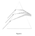
- FIG. 6 shows chromatic aberration compensated by filtering and convergence according to one aspect of the present invention.
- FIG. 7 shows examples of the utilization of an area of the image forming element according to certain aspects of the present invention.
- FIG. 8 shows a method for modifying light for display according to one aspect of the present invention.
- FIG. 9 shows an example of a dual projector system that includes anamorphic prisms according to one aspect of the present invention.
- FIG. 1A and FIG. 1B show side and top views, respectively, of a first aspect of the invention.
- a projection system is shown that includes a digital projector 1 located near the edge of a dome-shaped projection surface 2 , and an image generator 3 .
- the projector 1 can project an image onto the dome-shaped projection surface 2 .
- the projector 1 can include at least one image forming element with an aspect ratio R, which may be approximately 16:1 or approximately 17:1, and a projection objective with a horizontal emission angle of approximately 110 degrees and a vertical emission angle of at least 45 degrees, for example 50 degrees or 60 degrees.
- the projection objective may include a prime lens 4 , which may be a wide angle or fish eye objective.
- the wide angle or fish eye objective may have a mechanical aperture that is larger than one or more of the lens elements, clipping some rays, but allowing more light rays to pass through the center of the lens, resulting in a non-uniform brightness with light level falling off towards the edges of the image, an effect also known as “vignetting”.
- dome projection it can enable better light utilization at the center of interest of the projected image and at the same time reduce light levels at the dome edges in the peripheral part of the vision of the observers, thereby reducing cross reflections in the dome, which again may reduce the effective contrast in the center of interest of the projected image and which may otherwise result in low-contrast unpleasing images where colors appear unsaturated or “flat.”
- a configuration according to one aspect may further include an electronic image warping system 5 that can perform a geometric correction of the images being input to the projector 1 so that a technician can calibrate the projected images for a best possible experience compromise for the viewers located in different seats, including maintaining an essentially straight horizon for as many viewers as possible. This process may compensate for both distortion in the projection objective and the distortion caused by viewing the projected images off of the projection axis.
- FIG. 2 shows a configuration according to the first aspect in which an anamorphic adaptor that includes a first prism 6 and a second prism 7 is located in front of the prime lens 4 .
- the first prism 6 and the second prism 7 are replaced with cylindrical lenses.
- the prime lens 4 may have essentially equal magnification in the horizontal and vertical directions and the anamorphic adaptor may be oriented so it stretches the image in the vertical direction, resulting in a bigger magnification factor of the projection objective in the vertical than in the horizontal direction.
- the projector 1 may include a spectrum separation stereoscopic system that can cause the spectrum of the emitted light from the projector 1 to have essentially discrete and narrow red, green and blue wavelength bands, and the audience may wear 3D glasses with spectrum separation filters.
- the spectrum separation system may include a rotating filter wheel that may filter transmitted light alternately between two spectra, a static filter, a solid state alternating filter or a laser illumination system with a static or alternating light spectrum.
- the image warping system 5 may be capable of performing separate geometric corrections for each of the primary colors, allowing the technician to adjust the color convergence calibration of the red, green and blue image planes, for example by using a white calibration grid, thereby reducing the visual blurring caused by chromatic aberration in the prime lens 4 and in the anamorphic adaptor.
- the spectrum separation stereoscopic system is used, and the emitted spectrum therefore consists of narrow red, green and blue wavelength bands, it may be possible by the convergence calibration to reduce the blurring by chromatic aberration effectively. This, in turn, can reduce the need to use optical means in the prime lens 4 and the anamorphic adaptor to compensate for chromatic aberration.
- the spectrum separation stereoscopic system can alternate the emitted spectrum between a first spectrum and a second spectrum.
- the image generator 3 can output alternately left eye and right eye perspective images and the image warping system 5 can alternate synchronously between a first color convergence calibration and a second color convergence calibration. Two separate color convergence calibrations can be adjusted by the technician.
- a white grid is projected as the left eye image, a black image is projected as the right eye image, and the red and blue geometry is calibrated until the best possible color convergence
- a green grid is projected as both left and right eye perspective images and the green geometry of the second color convergence is calibrated to the best possible convergence between the two spectra of green
- a red grid is projected as both left and right eye perspective images and the red geometry of the second color convergence is calibrated to the best possible convergence between the two spectra of red
- a blue grid is projected as both left and right eye perspective images and the blue geometry of the second color convergence is calibrated to the best possible convergence between the two spectra of blue.
- the color convergence calibrations may be stored as separate geometry corrections that can be performed after a general geometry correction is performed that is calibrated for best experience compromise (i.e. straight horizon etc.). The performance of those two successive geometry corrections may be performed such that the resulting geometry correction for each of the six wavelength bands is first computed, then the color planes are resampled to avoid successive resamplings and the associated quality loss.
- a second projector 21 with a second prime lens 24 and a second anamorphic adaptor 26 , a second image generator 23 and a second image warping system 25 are added to the projector system of FIG. 3 .
- the projector 1 can emit light of a first spectrum and the second projector 21 can emit light of a second spectrum.
- the color convergence can be calibrated for each projector 1 , 21 separately in the respective image warping systems 5 , 25 .
- the anamorphic adaptor may be a traditional configuration of a prism pair.
- One purpose of a larger prism in such a traditional anamorphic adaptor is to counteract the chromatic aberration created in the smaller prism.
- the second prism With a horizontal projection angle of 110 degrees, the second prism can become very large and heavy and may result in a complicated and expensive practical implementation.
- FIG. 3 shows a configuration of the spectrum separation stereoscopic system.
- the image warping system 5 can perform separate geometric corrections for each of the primary colors.
- the second prism 7 used in FIG. 2 can be eliminated.
- the visual effects of the chromatic aberration can be eliminated by calibrating the color convergence.
- the prism can be located in a mount such that the vertical angle can be adjusted. Further, the mount may be constructed such that the prism can be changed. It may be possible, for example, to change between triangular prisms of different angles. By selecting between prisms of different angles and/or by adjusting the vertical angle of the prism, different vertical amplification can achieved.
- the image warping 5 may correct for the geometric distortion created by non-linear magnification in the vertical direction. The result of the non-linear magnification may be that geometry is conserved, but resolution and brightness reduced in the top of the dome, hence utilizing more of the available illumination and resolution in the center of interest and reducing contrast-reducing cross reflections onto the center of interest.
- both the general geometry calibration for best experience and the color convergence can be performed again.
- a link can be established between the selection and adjustment of prisms such that the geometrical corrections can follow the selected prism and angle.
- sensors may sense the selected prism and angle and send information data to the warping system 5 , which can select a relevant pre-calibrated geometry correction.
- a servo system may adjust the prism angle. The servo system and the warping system can be operated and synchronized by a control system.
- the projector 1 may be a 3 chip 4K DLPTM cinema projector with 1.38′′ DMD chips, for example a Christie CP4230 or a Barco DP4K.
- the prime lens 4 may be a fisheye objective with a focal length of app. 15 mm and an f# of 2.4.
- the aperture of the objective may be larger than that of some of the individual lens elements, which may increase brightness at the center (vignetting) and reduce brightness relatively in peripheral vision areas, hence reduce cross reflections in the dome.
- the spectrum separation stereoscopic system may be a DolbyTM 3D, Panavision 3D or Infitec alternating filter wheel or non-alternating filter.
- the warping system may be the geometry functions included in the 7 th Sense “Delta” media server.
- the anamorphic adaptor may consist of a single triangular prism with an angle of 10 degrees located in front of the prime lens with an adjustable vertical angle and the thinner edge facing down.
- the vertical angle may be adjusted depending on how big a fraction of the dome is desired to be covered with projected image, and may for example be set to 25 degrees.
- a prism can be n-BK7 glass with a wedge angle of 8.7 degrees and can produce a 33% image stretch in one direction.
- the selected prism may cause significant angular color separation as the light exits the prism.
- image warping unit 5 in FIG. 3 another problem may occur in which the narrow wavelength bandwidth of color spreads apart further angularly to create a fatter pixel.
- Image warping may not correct for a fatter pixel problem.
- using the n-BK7 glass prism with a 8.7 degree wedge angle can cause a pixel in a projection system with a 4k resolution image modulator to become fatter in one direction by as much as 66%. This scenario can be calculated for green light with a center wavelength of 532 nanometers and a bandwidth of +/ ⁇ 10 nanometers.
- each projected image pixel that is stretched by the single prism anamorphic adaptor and displayed on a screen can include three separate color pixel images to form a pixel image on the screen.
- Each color channel can have a bandwidth of wavelengths of light. The bandwidth of wavelengths of light for one color can converge on the space of one pixel on the screen. If the prism separates color to a greater extreme, the light associated with a color channel may spread out further angularly when exiting the prism, causing the displayed pixel to become fatter. The fatter the pixel becomes for each color pixel, blur can become apparent to a viewer, which is undesirable.
- Projection systems may use wideband light sources where color channels are created by color separating optical elements, such as a Philip's prism or color filters such as in a rotating color wheel. There can be a diminishing return between stretching the image with a single prism and image brightness to maintain image quality. For projection systems that rely on wideband light sources, further narrowing of the bandwidth for each color can be done but may not be an acceptable solution when further stretching of an image is performed.
- Another approach is to use very narrow band light sources, such as laser light sources in a projection system, with a single prism anamorphic projection adaptor.
- the laser source can have a very narrow bandwidth of wavelengths of light that can be used with a single prism element in combination with the warping unit 5 to correct for color shift on the display.
- a laser-based system can extend the stretch capability of the single prism element and the warping unit can compensate for the extra image color shift between color channels when displaying a stretched image.
- lasers with a +/ ⁇ 1 nanometer wavelength bandwidth about the center frequency can be used with a single prism anamorphic lens for virtually any amount of color separation and therefore any amount of image stretch.
- Another factor such as speckle can be considered when using very narrow band laser sources.
- One potential disadvantage of very narrow band laser sources is the amount of light speckle that these sources produce.
- Light speckle from a laser light source may appear on a display as an undesirable visible image artifact.
- the amount of speckle that can be observed may increase as the light wavelength bandwidth of the laser decreases.
- One approach to reducing speckle can be to increase the bandwidth of wavelengths of the laser light source.
- increased bandwidth can lead to a fat pixel problem for an extreme image stretch when using a single prism anamorphic adaptor.
- the bandwidth of wavelength of the laser source used in an extreme image stretch may be based on a compromise between the amount of speckle produced and the degree a pixel becomes blurred or fattened.
- each projected image can have a different narrow bandwidth of wavelengths of red, green and blue light.
- the maximum bandwidth of wavelengths of two different bandwidths in the same color channel, one for each eye image can be limited by the full range of the red or green or blue color spectrum considered acceptable for each color channel.
- wavelength limits of a red color channel can be defined in terms of what is considered to produce an acceptable viewing result for red colored images.
- two narrower wavelength bandwidths with a center frequency wavelength can be defined with sufficient wavelength separation between the two center frequencies and associated bandwidth to prevent undesirable color channel crossover.
- bandwidth of the laser light source can be further limited.
- the bandwidth of wavelengths of the laser light may be limited to less than 20 nanometers such as 10 nanometers to reduce the fat pixel further in the example above.
- FIG. 4 shows an example the effects of the chromatic aberration in the anamorphic prism.
- the prism angle and aberration is exaggerated here for illustrative purposes.
- a good quality prism located near infinite focus of projection objective and having its angle adjusted for moderate stretch can exhibit little of the different types of aberration, except for chromatic aberration that may be significant.
- the small beam is dispersed into a much wider beam, which in turn can create a significant blur on the screen.
- FIG. 5 shows the aberration with a narrowband filter, such as a DolbyTM 3D filter wheel, inserted. Some of the spectrum is removed and remaining are three narrow beams corresponding to the three narrow bands transmitted by the narrowband filter. Since the beams are separated spatially, the amount of blur is only reduced slightly.
- a wide wavelength bandwidth of light can exit the prism with a large angular spread, as shown in FIG. 4 . By narrowing the wavelength bandwidth that enters the prism, light can exit with much less angular spread, as shown in FIG. 5 .
- FIG. 6 shows the aberration again in which the projected image is digitally corrected geometrically, for example by the warping unit 5 in FIG. 3 , in each of the three color planes for color convergence.
- the three narrow beams hit on top of each other on the projection surface. Hence, the blur can be significantly reduced.
- FIG. 8 illustrates a method of projection using an optical distorting element such as a single prism anamorphic adaptor.
- an optical distorting element such as a single prism anamorphic adaptor.
- One example of a projection system with a single prism anamorphic element usable for performing the method of FIG. 8 is the projection system shown in FIG. 3 .
- Other projection systems may of course be used.
- the wavelength bandwidth of light for one color channel is adjusted.
- the wavelength bandwidth is adjusted after an image is displayed using light that has been stretched using a single prism anamorphic adapted and modified in at least one color channel with image data.
- the light with the adjusted wavelength bandwidth can then be modified, stretched, and displayed again as described in the following section.
- the bandwidth can be adjusted to work with a single prism anamorphic adaptor to achieve an optimum image stretch that would not be otherwise possible because of a fat pixel problem that color warping techniques may not be able to correct. Adjusting by reducing the bandwidth of light in a color channel can reduce the angular spread of light exiting a one prism anamorphic adaptor. Effectively, the fat pixel problem can be controlled. Examples of techniques for adjusting color channel bandwidth include adding a color filter, adding an adjustable color filter, having interchangeable color filters, and having interchangeable color wheel filters. An alternate approach can involve designing the light source to have light emissions with the needed wavelength bandwidth profile best suited for the single lens prism anamorphic adaptor to minimize a fat pixel problem. Another approach may be to use a source with as narrow as possible wavelength bandwidth of light for a color channel such as a laser source. A diode laser is an example of one such laser that can be used as a light source with a much reduced fat pixel problem.
- one color channel of the light is modified with image data to produce modified image light.
- Image data can be accessed in any number of ways such as from a server in the projection system, from a server that is remote with respect to the projection system, or it can be accessed remotely.
- Image data can be a feature presentation.
- An example of a device that can perform the modification is a spatial light modulator (SLM) 10 of FIG. 3 , or otherwise a device that uses electrical input data such as image data to modify received light that is not imaged to produce imaged light.
- SLM devices 10 include a Digital Mirror Device (DMD), or Liquid Crystal on Silicon (LCOS) device, or a Liquid Crystal (LC) device.
- DMD Digital Mirror Device
- LCOS Liquid Crystal on Silicon
- LC Liquid Crystal
- the light received by the SLM 10 can be from a color channel or several color channels.
- the color channels can be red, green, and blue.
- Wideband light sources such as xenon lamps can output a broad spectrum of light in which filters, or a Philips prism, can be used to separate the light into the three color channels.
- filters or a Philips prism
- each light channel can have as large as possible bandwidth within a limited spectrum to ensure much of the light for each color is available to produce a bright image.
- Digital projection system using SLMs may typically be setup to display the brightest image possible. However, when configuring such systems to display an image that is stretched, the wavelength bandwidth of light for each color can become limiting in terms of how much image stretch can be done.
- the image data in block 824 can also be modified image data that has been modified by a color warping processor.
- Image data can be warped to cause the imaged light from one color channel to converge on to the display screen with imaged light from another color channel.
- the warping unit 5 in FIG. 3 can perform the convergence function.
- the projected image from a projection lens can be stretched by a single prism anamorphic adaptor.
- FIG. 3 illustrates a projection system with a projection lens 4 and a single prism element 6 in which the image is stretched in the vertical direction.
- the prism element 6 can have a slim prism angle (for example 10 degrees) such that the stretch is not so large and color separation is not as significant.
- the slim prism can be made of low dispersion glass and be designed such that coma aberrations are minimal and manageable. As the prism angle of the slim prism increases, greater image stretching is possible. With typical projection systems using wideband light sources and separating the light into color channels, the amount of image stretch may be limited by the bandwidth of the light in a color channel.
- the stretched image is displayed.
- images are displayed on projection surfaces or screens.
- the stretched image can be displayed on a domed projection surface 2 in FIG. 3 .
- the dome shaped projection surface in the configurations of FIG. 2 or FIG. 3 , can be substituted by another shape, such as a rectilinear screen which may be a large flat or curved projection surface covering a large fraction of the observer's field of vision so an immersive experience is achieved.
- the projection surface may have an aspect ratio higher in the vertical direction than the aspect ratio R of the image forming element.
- the prism 6 and/or the prism 7 may be adjusted so that the image can essentially fill out the projection surface and eliminate “black bars” on the top and bottom of the projection surface.
- FIG. 7 shows an example of the utilization of the area of the image forming element with 702 and without 704 the anamorphic adapter (not shown) located in front of the prime lens (not shown).
Landscapes
- Engineering & Computer Science (AREA)
- Multimedia (AREA)
- Signal Processing (AREA)
- Physics & Mathematics (AREA)
- General Physics & Mathematics (AREA)
- Optics & Photonics (AREA)
- Geometry (AREA)
- Spectroscopy & Molecular Physics (AREA)
- Projection Apparatus (AREA)
- Lenses (AREA)
Abstract
Description
Claims (20)
Priority Applications (1)
| Application Number | Priority Date | Filing Date | Title |
|---|---|---|---|
| US15/292,340 US10073328B2 (en) | 2011-10-20 | 2016-10-13 | Reducing angular spread in digital image projection |
Applications Claiming Priority (4)
| Application Number | Priority Date | Filing Date | Title |
|---|---|---|---|
| US201161549601P | 2011-10-20 | 2011-10-20 | |
| PCT/IB2012/055754 WO2013057717A1 (en) | 2011-10-20 | 2012-10-19 | Distortion compensation for image projection |
| US201414351816A | 2014-04-14 | 2014-04-14 | |
| US15/292,340 US10073328B2 (en) | 2011-10-20 | 2016-10-13 | Reducing angular spread in digital image projection |
Related Parent Applications (2)
| Application Number | Title | Priority Date | Filing Date |
|---|---|---|---|
| US14/351,816 Continuation US9503711B2 (en) | 2011-10-20 | 2012-10-19 | Reducing angular spread in digital image projection |
| PCT/IB2012/055754 Continuation WO2013057717A1 (en) | 2011-10-20 | 2012-10-19 | Distortion compensation for image projection |
Publications (2)
| Publication Number | Publication Date |
|---|---|
| US20170034488A1 US20170034488A1 (en) | 2017-02-02 |
| US10073328B2 true US10073328B2 (en) | 2018-09-11 |
Family
ID=48140429
Family Applications (2)
| Application Number | Title | Priority Date | Filing Date |
|---|---|---|---|
| US14/351,816 Active US9503711B2 (en) | 2011-10-20 | 2012-10-19 | Reducing angular spread in digital image projection |
| US15/292,340 Active US10073328B2 (en) | 2011-10-20 | 2016-10-13 | Reducing angular spread in digital image projection |
Family Applications Before (1)
| Application Number | Title | Priority Date | Filing Date |
|---|---|---|---|
| US14/351,816 Active US9503711B2 (en) | 2011-10-20 | 2012-10-19 | Reducing angular spread in digital image projection |
Country Status (4)
| Country | Link |
|---|---|
| US (2) | US9503711B2 (en) |
| EP (1) | EP2769261B1 (en) |
| CN (2) | CN109889813B (en) |
| WO (1) | WO2013057717A1 (en) |
Families Citing this family (7)
| Publication number | Priority date | Publication date | Assignee | Title |
|---|---|---|---|---|
| EP2564374B1 (en) | 2010-04-18 | 2014-11-19 | Imax Corporation | Double stacked projection |
| EP3675481B1 (en) | 2011-08-16 | 2024-11-20 | Imax Corporation | Hybrid image decomposition and projection |
| US9641826B1 (en) * | 2011-10-06 | 2017-05-02 | Evans & Sutherland Computer Corporation | System and method for displaying distant 3-D stereo on a dome surface |
| CN109889813B (en) | 2011-10-20 | 2021-02-23 | 图象公司 | Distortion compensation for image projection |
| WO2013057714A1 (en) | 2011-10-20 | 2013-04-25 | Imax Corporation | Invisible or low perceptibility of image alignment in dual projection systems |
| JP7647416B2 (en) * | 2021-07-26 | 2025-03-18 | セイコーエプソン株式会社 | METHOD FOR CONTROLLING PROJECTOR AND PROJECTOR |
| US20240046577A1 (en) * | 2022-08-05 | 2024-02-08 | Samsung Electronics Co., Ltd. | Video See-Through Augmented Reality |
Citations (106)
| Publication number | Priority date | Publication date | Assignee | Title |
|---|---|---|---|---|
| DE2827622A1 (en) | 1978-06-23 | 1980-01-03 | Heinz Arnold | Montage slide projection appts. - provides masking facility for combination with second projector for montage inset |
| US4523226A (en) | 1982-01-27 | 1985-06-11 | Stereographics Corporation | Stereoscopic television system |
| US4868773A (en) | 1985-03-15 | 1989-09-19 | Purdue Research Foundation | Digital filtering by threshold decomposition |
| US5070403A (en) | 1989-04-21 | 1991-12-03 | Sony Corporation | Video signal interpolation |
| US5384869A (en) | 1991-12-24 | 1995-01-24 | Sony United Kingdom Limited | Image processing apparatus |
| DE19545356A1 (en) | 1995-12-05 | 1996-05-09 | Vidisys Video Und Digital Syst | Displaying stereo-video images on monitor, projectors etc. |
| JPH08168039A (en) | 1994-12-14 | 1996-06-25 | Nippon Telegr & Teleph Corp <Ntt> | Projection display system and projection position adjusting method |
| WO1996021171A2 (en) | 1995-01-04 | 1996-07-11 | Visualabs Inc. | 3-d imaging system |
| US5561474A (en) | 1992-01-13 | 1996-10-01 | Mitsubishi Denki Kabushiki Kaisha | Superimposing circuit performing superimposing based on a color saturation level determined from color difference signals |
| JPH0946553A (en) | 1995-07-26 | 1997-02-14 | Graphics Commun Lab:Kk | Filter |
| US5631975A (en) | 1992-04-14 | 1997-05-20 | Koninkl Philips Electronics Nv | Image segmentation device |
| US5654805A (en) | 1993-12-29 | 1997-08-05 | Matsushita Electric Industrial Co., Ltd. | Multiplexing/demultiplexing method for superimposing sub-images on a main image |
| US5663775A (en) | 1994-04-27 | 1997-09-02 | Mitsubishi Denki Kabushiki Kaisha | Video projector with luminance and chrominance optical modulation LCD's |
| JPH09326981A (en) | 1996-06-06 | 1997-12-16 | Olympus Optical Co Ltd | Image projection system |
| EP0899688A2 (en) | 1997-08-29 | 1999-03-03 | Fujitsu Limited | Device for generating, detecting, recording, and reproducing a watermarked moving image |
| US5920652A (en) | 1996-03-20 | 1999-07-06 | Sony Corporation | Method and apparatus for dividing an input image into a plurality of images of different frequency bandwidths |
| US6018596A (en) | 1996-03-20 | 2000-01-25 | Sony Corporation | Method and apparatus for processing an input image |
| JP2000184317A (en) | 1998-12-21 | 2000-06-30 | Nippon Hoso Kyokai <Nhk> | Projection type multi-screen display device |
| US6128415A (en) | 1996-09-06 | 2000-10-03 | Polaroid Corporation | Device profiles for use in a digital image processing system |
| JP2001051346A (en) | 1999-08-05 | 2001-02-23 | Nippon Telegr & Teleph Corp <Ntt> | Automatic pixel position adjustment device |
| RU2165192C1 (en) | 1999-08-17 | 2001-04-20 | Кубанский государственный технологический университет | Method for producing juice from vegetable raw materials |
| US6243070B1 (en) | 1998-10-07 | 2001-06-05 | Microsoft Corporation | Method and apparatus for detecting and reducing color artifacts in images |
| US20010024231A1 (en) | 2000-03-21 | 2001-09-27 | Olympus Optical Co., Ltd. | Stereoscopic image projection device, and correction amount computing device thereof |
| US20020027608A1 (en) | 1998-09-23 | 2002-03-07 | Honeywell, Inc. | Method and apparatus for calibrating a tiled display |
| US6396505B1 (en) | 1998-10-07 | 2002-05-28 | Microsoft Corporation | Methods and apparatus for detecting and reducing color errors in images |
| CN1367883A (en) | 1998-07-09 | 2002-09-04 | 斯夫亚托斯拉夫·伊万诺维奇·阿森尼奇 | Projection system |
| US20020196538A1 (en) * | 2001-06-06 | 2002-12-26 | Lantz Edward J. | Video-based immersive theater |
| EP1297488A1 (en) | 2000-07-05 | 2003-04-02 | Smart Technologies Inc. | Camera-based touch system |
| US6552855B1 (en) | 2001-11-06 | 2003-04-22 | Eastman Kodak Company | Image-forming system with enhanced gray levels |
| US20040001184A1 (en) | 2000-07-03 | 2004-01-01 | Gibbons Michael A | Equipment and techniques for increasing the dynamic range of a projection system |
| US6703988B1 (en) | 1999-07-08 | 2004-03-09 | Fergason Patent Properties, Llc | Monitor for showing high-resolution and three-dimensional images and method |
| WO2004039085A1 (en) | 2002-10-21 | 2004-05-06 | Imax Corporation | Equipment, systems and methods for control of color in projection displays |
| US20040085256A1 (en) | 2002-10-30 | 2004-05-06 | The University Of Chicago | Methods and measurement engine for aligning multi-projector display systems |
| US6733138B2 (en) | 2001-08-15 | 2004-05-11 | Mitsubishi Electric Research Laboratories, Inc. | Multi-projector mosaic with automatic registration |
| US6751006B2 (en) | 2000-07-03 | 2004-06-15 | Imax Corporation | Processing techniques for superimposing images for image projection |
| US6760075B2 (en) | 2000-06-13 | 2004-07-06 | Panoram Technologies, Inc. | Method and apparatus for seamless integration of multiple video projectors |
| EP1460856A2 (en) | 2003-03-20 | 2004-09-22 | Eastman Kodak Company | Projection apparatus using telecentric optics |
| US6804406B1 (en) | 2000-08-30 | 2004-10-12 | Honeywell International Inc. | Electronic calibration for seamless tiled display using optical function generator |
| US20040239885A1 (en) | 2003-04-19 | 2004-12-02 | University Of Kentucky Research Foundation | Super-resolution overlay in multi-projector displays |
| US6843564B2 (en) | 2002-01-04 | 2005-01-18 | Neurok Llc | Three-dimensional image projection employing retro-reflective screens |
| US20050036673A1 (en) | 2003-05-20 | 2005-02-17 | Namco Ltd. | Image processing system, program, information storage medium, and image processing method |
| CN1598690A (en) | 2003-09-19 | 2005-03-23 | 邓兴峰 | Screen division stereoscopic photography projection instrument |
| US20050082990A1 (en) | 2003-05-20 | 2005-04-21 | Elliott Candice H.B. | Projector systems |
| US20050083402A1 (en) | 2002-10-31 | 2005-04-21 | Stefan Klose | Auto-calibration of multi-projector systems |
| US6984043B2 (en) | 2002-05-23 | 2006-01-10 | Olympus Optical Co., Ltd. | Image display apparatus for displaying superimposed images from a plurality of projectors |
| CN1735173A (en) | 2004-08-11 | 2006-02-15 | 精工爱普生株式会社 | Display device and method for generating image information in display device |
| US7002533B2 (en) | 2001-08-17 | 2006-02-21 | Michel Sayag | Dual-stage high-contrast electronic image display |
| JP2006139057A (en) | 2004-11-12 | 2006-06-01 | Seiko Epson Corp | Image display apparatus, image display method, program capable of executing this method by computer, and computer-readable recording medium recording this program |
| US7079157B2 (en) | 2000-03-17 | 2006-07-18 | Sun Microsystems, Inc. | Matching the edges of multiple overlapping screen images |
| US7111941B2 (en) | 2004-08-25 | 2006-09-26 | Hewlett-Packard Development Company, L.P. | Method and apparatus for multiple-resolution light value projector |
| US20060221249A1 (en) | 2005-03-30 | 2006-10-05 | Samsung Electronics Co., Ltd. | Dual-channel adaptive 2D noise reduction for video signals |
| CN1846213A (en) | 2003-07-25 | 2006-10-11 | 斯瑞毕国际有限公司 | the message says |
| US7127084B1 (en) | 2002-03-22 | 2006-10-24 | Mauk Jamey R | Method of creating digital composite files of superimposed images |
| WO2006116536A1 (en) | 2005-04-26 | 2006-11-02 | Imax Corporation | Electronic projection systems and methods |
| US20070024764A1 (en) | 2005-07-29 | 2007-02-01 | Optoma Technology, Inc. | Methods and systems that compensate for distortion introduced by anamorphic lenses in a video projector |
| US20070091277A1 (en) | 2005-10-26 | 2007-04-26 | Niranjan Damera-Venkata | Luminance based multiple projector system |
| US20070132965A1 (en) | 2005-12-12 | 2007-06-14 | Niranjan Damera-Venkata | System and method for displaying an image |
| US20070133794A1 (en) | 2005-12-09 | 2007-06-14 | Cloutier Frank L | Projection of overlapping sub-frames onto a surface |
| CN1988674A (en) | 2005-12-21 | 2007-06-27 | 国际商业机器公司 | Method and device for three-dimensional projection |
| US20070171380A1 (en) | 2006-01-26 | 2007-07-26 | Christie Digital Systems Inc. | Calibration of a super-resolution display |
| US20070285663A1 (en) | 2006-06-12 | 2007-12-13 | The Boeing Company | Efficient and accurate alignment of stereoscopic displays |
| US7339625B2 (en) | 2004-06-28 | 2008-03-04 | Barco N.V. | Optical and electrical blending of display images |
| US7357517B2 (en) | 2005-02-16 | 2008-04-15 | Seiko Epson Corporation | Projector, method of controlling the projector, program for controlling the projector, and recording medium storing the program |
| US20080101725A1 (en) | 2006-10-26 | 2008-05-01 | I-Jong Lin | Image display system configured to update correspondences using arbitrary features |
| US20080143969A1 (en) | 2006-12-15 | 2008-06-19 | Richard Aufranc | Dynamic superposition system and method for multi-projection display |
| US20080143978A1 (en) | 2006-10-31 | 2008-06-19 | Niranjan Damera-Venkata | Image display system |
| JP2008182706A (en) | 2007-01-24 | 2008-08-07 | Seiko Epson Corp | A method for imposing simulated display constraints on the light transport matrix T of a projector-camera system in a given scene, and a first projection image from a first projector-camera system and a second projector-camera system Method for mosaicking second projection image |
| US20080266321A1 (en) | 2007-04-30 | 2008-10-30 | Richard Aufranc | System and method for masking and overlaying images in multiple projector system |
| US20080297451A1 (en) | 2007-05-30 | 2008-12-04 | Gabriel Marcu | Methods and apparatuses for increasing the apparent brightness of a display |
| US20090027304A1 (en) | 2007-07-25 | 2009-01-29 | Richard Aufranc | Projector alignment in a multiple-projector projection system |
| JP2009069818A (en) | 2007-08-09 | 2009-04-02 | Barco Nv | Display system, method for driving display system, control unit, computer program product, and machine-readable data storage device |
| US20090102915A1 (en) | 2005-04-25 | 2009-04-23 | Svyatoslav Ivanovich Arsenich | Stereoprojection system |
| CN101507286A (en) | 2006-08-17 | 2009-08-12 | 索尼爱立信移动通讯股份有限公司 | Adjustment of projector |
| US20090213337A1 (en) | 2008-02-26 | 2009-08-27 | Sony Corporation | Image projecting system, method, computer program and recording medium |
| US20090244684A1 (en) | 2008-03-27 | 2009-10-01 | Jacques Gollier | Systems and methods for speckle reduction |
| US20090273719A1 (en) | 2007-08-30 | 2009-11-05 | Mitsubishi Electric Corporation | Image projection apparatus and projection optical system |
| JP2009260932A (en) | 2008-03-26 | 2009-11-05 | Seiko Epson Corp | Image processing apparatus and image processing method in multi-projection system, and multi-projection system |
| US20090278918A1 (en) | 2008-05-07 | 2009-11-12 | Marcus Michael A | Display using bidirectionally scanned linear modulator |
| US20100008568A1 (en) | 2003-07-15 | 2010-01-14 | Stmicroelectronics S.R.L. | Method for classifying a digital image |
| US7660470B2 (en) | 2003-10-16 | 2010-02-09 | Ricoh Company, Ltd. | System and method for generating superimposed image data |
| JP2010039160A (en) | 2008-08-05 | 2010-02-18 | Seiko Epson Corp | Image processing device, image display, image processing method, image display method and program |
| US7676072B2 (en) | 2005-06-15 | 2010-03-09 | Kabushiki Kaisha Toshiba | Image processing apparatus and image processing method |
| US20100103379A1 (en) | 2008-10-24 | 2010-04-29 | Reinhold Fiess | Method for generating an image and a projector and a cell phone having a projector |
| US7740361B2 (en) | 2006-04-21 | 2010-06-22 | Mersive Technologies, Inc. | Alignment optimization in image display systems employing multi-camera image acquisition |
| US20100177112A1 (en) | 2007-05-25 | 2010-07-15 | Nec Carporation | Image processing device, its method and program, and display device |
| US20100201682A1 (en) | 2009-02-06 | 2010-08-12 | The Hong Kong University Of Science And Technology | Generating three-dimensional fadeçade models from images |
| US7852327B2 (en) | 2005-04-11 | 2010-12-14 | Samsung Electronics Co., Ltd. | Display apparatus and control method thereof |
| WO2010147451A1 (en) | 2009-06-15 | 2010-12-23 | Mimos Berhad | An online orthogonal projection system |
| US7866832B2 (en) | 2006-02-15 | 2011-01-11 | Mersive Technologies, Llc | Multi-projector intensity blending system |
| US7891818B2 (en) | 2006-12-12 | 2011-02-22 | Evans & Sutherland Computer Corporation | System and method for aligning RGB light in a single modulator projector |
| JP2011040958A (en) | 2009-08-10 | 2011-02-24 | Sony Corp | Image display device and image display method |
| US20110057943A1 (en) | 2009-09-10 | 2011-03-10 | Victor Ivashin | Balancing Luminance Disparity in a Display by Multiple Projectors |
| US7954954B2 (en) | 2007-07-31 | 2011-06-07 | Hewlett-Packard Development Company, L.P. | System and method of projecting an image using a plurality of projectors |
| CN102123292A (en) | 2006-04-19 | 2011-07-13 | 塞特雷德股份公司 | Bandwidth improvement for 3D display |
| US20110199586A1 (en) | 2010-02-12 | 2011-08-18 | Seiko Epson Corporation | Projector and anamorphic prism optical unit |
| US8016426B2 (en) | 2008-02-27 | 2011-09-13 | 6115187 Canada Inc. | Method and device for projecting a panoramic image with a variable resolution |
| US20110234920A1 (en) | 2010-03-24 | 2011-09-29 | Steve Nelson | Method for Creating Blending Ramps for Complex Projector Image Overlaps |
| WO2011134834A2 (en) | 2010-04-18 | 2011-11-03 | Sirius Digital Aps | Double stacked projection |
| US20110309999A1 (en) | 2009-02-11 | 2011-12-22 | Nelson Liang An Chang | Multi-projector system and method |
| WO2011160629A1 (en) | 2010-06-21 | 2011-12-29 | Sirius Digital Aps | Double stacked projection |
| US20120127323A1 (en) | 2009-09-10 | 2012-05-24 | Yuuji Kasuya | Projection image area detecting device |
| US20120176415A1 (en) | 2011-01-06 | 2012-07-12 | Telenav, Inc. | Graphical display system with adaptive keystone mechanism and method of operation thereof |
| WO2013024430A1 (en) | 2011-08-16 | 2013-02-21 | Imax Corporation | Hybrid image decomposition and projection |
| WO2013057714A1 (en) | 2011-10-20 | 2013-04-25 | Imax Corporation | Invisible or low perceptibility of image alignment in dual projection systems |
| WO2013057717A1 (en) | 2011-10-20 | 2013-04-25 | Imax Corporation | Distortion compensation for image projection |
| US8453148B1 (en) | 2005-04-06 | 2013-05-28 | Teradici Corporation | Method and system for image sequence transfer scheduling and restricting the image sequence generation |
Family Cites Families (4)
| Publication number | Priority date | Publication date | Assignee | Title |
|---|---|---|---|---|
| US20030067537A1 (en) * | 2001-10-04 | 2003-04-10 | Myers Kenneth J. | System and method for three-dimensional data acquisition |
| JP2006054532A (en) | 2004-08-10 | 2006-02-23 | Keystone International Kk | Mobile phone receiver and mobile phone call system |
| JP4291837B2 (en) * | 2006-08-30 | 2009-07-08 | 株式会社沖データ | Projection display apparatus and image forming apparatus |
| CN101109488A (en) * | 2007-08-23 | 2008-01-23 | 福州高意光学有限公司 | Multiple primary color LED luminous structure and application in projector and lighting system |
-
2012
- 2012-10-19 CN CN201910143435.4A patent/CN109889813B/en active Active
- 2012-10-19 WO PCT/IB2012/055754 patent/WO2013057717A1/en not_active Ceased
- 2012-10-19 US US14/351,816 patent/US9503711B2/en active Active
- 2012-10-19 EP EP12841614.6A patent/EP2769261B1/en not_active Not-in-force
- 2012-10-19 CN CN201280051370.7A patent/CN103890638B/en not_active Expired - Fee Related
-
2016
- 2016-10-13 US US15/292,340 patent/US10073328B2/en active Active
Patent Citations (129)
| Publication number | Priority date | Publication date | Assignee | Title |
|---|---|---|---|---|
| DE2827622A1 (en) | 1978-06-23 | 1980-01-03 | Heinz Arnold | Montage slide projection appts. - provides masking facility for combination with second projector for montage inset |
| US4523226A (en) | 1982-01-27 | 1985-06-11 | Stereographics Corporation | Stereoscopic television system |
| US4868773A (en) | 1985-03-15 | 1989-09-19 | Purdue Research Foundation | Digital filtering by threshold decomposition |
| US5070403A (en) | 1989-04-21 | 1991-12-03 | Sony Corporation | Video signal interpolation |
| US5384869A (en) | 1991-12-24 | 1995-01-24 | Sony United Kingdom Limited | Image processing apparatus |
| US5561474A (en) | 1992-01-13 | 1996-10-01 | Mitsubishi Denki Kabushiki Kaisha | Superimposing circuit performing superimposing based on a color saturation level determined from color difference signals |
| US5631975A (en) | 1992-04-14 | 1997-05-20 | Koninkl Philips Electronics Nv | Image segmentation device |
| US5654805A (en) | 1993-12-29 | 1997-08-05 | Matsushita Electric Industrial Co., Ltd. | Multiplexing/demultiplexing method for superimposing sub-images on a main image |
| US5663775A (en) | 1994-04-27 | 1997-09-02 | Mitsubishi Denki Kabushiki Kaisha | Video projector with luminance and chrominance optical modulation LCD's |
| JPH08168039A (en) | 1994-12-14 | 1996-06-25 | Nippon Telegr & Teleph Corp <Ntt> | Projection display system and projection position adjusting method |
| WO1996021171A2 (en) | 1995-01-04 | 1996-07-11 | Visualabs Inc. | 3-d imaging system |
| RU2168192C2 (en) | 1995-01-04 | 2001-05-27 | Визуалабс Инк. | Visual image display and procedure forming three- dimensional image |
| JPH0946553A (en) | 1995-07-26 | 1997-02-14 | Graphics Commun Lab:Kk | Filter |
| DE19545356A1 (en) | 1995-12-05 | 1996-05-09 | Vidisys Video Und Digital Syst | Displaying stereo-video images on monitor, projectors etc. |
| US6018596A (en) | 1996-03-20 | 2000-01-25 | Sony Corporation | Method and apparatus for processing an input image |
| US5920652A (en) | 1996-03-20 | 1999-07-06 | Sony Corporation | Method and apparatus for dividing an input image into a plurality of images of different frequency bandwidths |
| US6538705B1 (en) | 1996-06-06 | 2003-03-25 | Olympus Optical Co., Ltd. | Image projecting system |
| JPH09326981A (en) | 1996-06-06 | 1997-12-16 | Olympus Optical Co Ltd | Image projection system |
| US6222593B1 (en) | 1996-06-06 | 2001-04-24 | Olympus Optical Co. Ltd. | Image projecting system |
| US6128415A (en) | 1996-09-06 | 2000-10-03 | Polaroid Corporation | Device profiles for use in a digital image processing system |
| EP0899688A2 (en) | 1997-08-29 | 1999-03-03 | Fujitsu Limited | Device for generating, detecting, recording, and reproducing a watermarked moving image |
| CN1367883A (en) | 1998-07-09 | 2002-09-04 | 斯夫亚托斯拉夫·伊万诺维奇·阿森尼奇 | Projection system |
| US20020027608A1 (en) | 1998-09-23 | 2002-03-07 | Honeywell, Inc. | Method and apparatus for calibrating a tiled display |
| US6243070B1 (en) | 1998-10-07 | 2001-06-05 | Microsoft Corporation | Method and apparatus for detecting and reducing color artifacts in images |
| US6396505B1 (en) | 1998-10-07 | 2002-05-28 | Microsoft Corporation | Methods and apparatus for detecting and reducing color errors in images |
| JP2000184317A (en) | 1998-12-21 | 2000-06-30 | Nippon Hoso Kyokai <Nhk> | Projection type multi-screen display device |
| US6703988B1 (en) | 1999-07-08 | 2004-03-09 | Fergason Patent Properties, Llc | Monitor for showing high-resolution and three-dimensional images and method |
| JP2001051346A (en) | 1999-08-05 | 2001-02-23 | Nippon Telegr & Teleph Corp <Ntt> | Automatic pixel position adjustment device |
| RU2165192C1 (en) | 1999-08-17 | 2001-04-20 | Кубанский государственный технологический университет | Method for producing juice from vegetable raw materials |
| US7079157B2 (en) | 2000-03-17 | 2006-07-18 | Sun Microsystems, Inc. | Matching the edges of multiple overlapping screen images |
| US20010024231A1 (en) | 2000-03-21 | 2001-09-27 | Olympus Optical Co., Ltd. | Stereoscopic image projection device, and correction amount computing device thereof |
| US6760075B2 (en) | 2000-06-13 | 2004-07-06 | Panoram Technologies, Inc. | Method and apparatus for seamless integration of multiple video projectors |
| US6751006B2 (en) | 2000-07-03 | 2004-06-15 | Imax Corporation | Processing techniques for superimposing images for image projection |
| US20040001184A1 (en) | 2000-07-03 | 2004-01-01 | Gibbons Michael A | Equipment and techniques for increasing the dynamic range of a projection system |
| EP1297488A1 (en) | 2000-07-05 | 2003-04-02 | Smart Technologies Inc. | Camera-based touch system |
| US6804406B1 (en) | 2000-08-30 | 2004-10-12 | Honeywell International Inc. | Electronic calibration for seamless tiled display using optical function generator |
| US20020196538A1 (en) * | 2001-06-06 | 2002-12-26 | Lantz Edward J. | Video-based immersive theater |
| US6733138B2 (en) | 2001-08-15 | 2004-05-11 | Mitsubishi Electric Research Laboratories, Inc. | Multi-projector mosaic with automatic registration |
| US7002533B2 (en) | 2001-08-17 | 2006-02-21 | Michel Sayag | Dual-stage high-contrast electronic image display |
| CN1417637A (en) | 2001-11-06 | 2003-05-14 | 伊斯曼柯达公司 | Image forming system with raised grey scale |
| US6552855B1 (en) | 2001-11-06 | 2003-04-22 | Eastman Kodak Company | Image-forming system with enhanced gray levels |
| US6843564B2 (en) | 2002-01-04 | 2005-01-18 | Neurok Llc | Three-dimensional image projection employing retro-reflective screens |
| US7127084B1 (en) | 2002-03-22 | 2006-10-24 | Mauk Jamey R | Method of creating digital composite files of superimposed images |
| US6984043B2 (en) | 2002-05-23 | 2006-01-10 | Olympus Optical Co., Ltd. | Image display apparatus for displaying superimposed images from a plurality of projectors |
| WO2004039085A1 (en) | 2002-10-21 | 2004-05-06 | Imax Corporation | Equipment, systems and methods for control of color in projection displays |
| US20040085256A1 (en) | 2002-10-30 | 2004-05-06 | The University Of Chicago | Methods and measurement engine for aligning multi-projector display systems |
| US20050083402A1 (en) | 2002-10-31 | 2005-04-21 | Stefan Klose | Auto-calibration of multi-projector systems |
| CN1532586A (en) | 2003-03-20 | 2004-09-29 | ��˹���´﹫˾ | Projector using trelecentric optical system |
| US20040184007A1 (en) | 2003-03-20 | 2004-09-23 | Eastman Kodak Company | Projection apparatus using telecentric optics |
| EP1460856A2 (en) | 2003-03-20 | 2004-09-22 | Eastman Kodak Company | Projection apparatus using telecentric optics |
| US20040239885A1 (en) | 2003-04-19 | 2004-12-02 | University Of Kentucky Research Foundation | Super-resolution overlay in multi-projector displays |
| US7097311B2 (en) | 2003-04-19 | 2006-08-29 | University Of Kentucky Research Foundation | Super-resolution overlay in multi-projector displays |
| US20050082990A1 (en) | 2003-05-20 | 2005-04-21 | Elliott Candice H.B. | Projector systems |
| US20050036673A1 (en) | 2003-05-20 | 2005-02-17 | Namco Ltd. | Image processing system, program, information storage medium, and image processing method |
| US20100008568A1 (en) | 2003-07-15 | 2010-01-14 | Stmicroelectronics S.R.L. | Method for classifying a digital image |
| CN1846213A (en) | 2003-07-25 | 2006-10-11 | 斯瑞毕国际有限公司 | the message says |
| CN1598690A (en) | 2003-09-19 | 2005-03-23 | 邓兴峰 | Screen division stereoscopic photography projection instrument |
| US7660470B2 (en) | 2003-10-16 | 2010-02-09 | Ricoh Company, Ltd. | System and method for generating superimposed image data |
| US7339625B2 (en) | 2004-06-28 | 2008-03-04 | Barco N.V. | Optical and electrical blending of display images |
| US20060033890A1 (en) | 2004-08-11 | 2006-02-16 | Seiko Epson Corporation | Display apparatus and image information generating method adapted to display apparatus |
| JP2006054632A (en) | 2004-08-11 | 2006-02-23 | Seiko Epson Corp | Display device and image information generation method in display device |
| CN1735173A (en) | 2004-08-11 | 2006-02-15 | 精工爱普生株式会社 | Display device and method for generating image information in display device |
| US7111941B2 (en) | 2004-08-25 | 2006-09-26 | Hewlett-Packard Development Company, L.P. | Method and apparatus for multiple-resolution light value projector |
| JP2006139057A (en) | 2004-11-12 | 2006-06-01 | Seiko Epson Corp | Image display apparatus, image display method, program capable of executing this method by computer, and computer-readable recording medium recording this program |
| US7357517B2 (en) | 2005-02-16 | 2008-04-15 | Seiko Epson Corporation | Projector, method of controlling the projector, program for controlling the projector, and recording medium storing the program |
| US20060221249A1 (en) | 2005-03-30 | 2006-10-05 | Samsung Electronics Co., Ltd. | Dual-channel adaptive 2D noise reduction for video signals |
| US8453148B1 (en) | 2005-04-06 | 2013-05-28 | Teradici Corporation | Method and system for image sequence transfer scheduling and restricting the image sequence generation |
| US7852327B2 (en) | 2005-04-11 | 2010-12-14 | Samsung Electronics Co., Ltd. | Display apparatus and control method thereof |
| US20090102915A1 (en) | 2005-04-25 | 2009-04-23 | Svyatoslav Ivanovich Arsenich | Stereoprojection system |
| US20080309884A1 (en) | 2005-04-26 | 2008-12-18 | O'dor Matthew | Electronic Projection Systems and Methods |
| JP2008539675A (en) | 2005-04-26 | 2008-11-13 | アイマックス コーポレイション | Electronic projection system and method |
| US8567953B2 (en) | 2005-04-26 | 2013-10-29 | Imax Corporation | Systems and methods for projecting composite images |
| WO2006116536A1 (en) | 2005-04-26 | 2006-11-02 | Imax Corporation | Electronic projection systems and methods |
| CN101180873A (en) | 2005-04-26 | 2008-05-14 | 图象公司 | Electronic projection systems and methods |
| US7676072B2 (en) | 2005-06-15 | 2010-03-09 | Kabushiki Kaisha Toshiba | Image processing apparatus and image processing method |
| US20070024764A1 (en) | 2005-07-29 | 2007-02-01 | Optoma Technology, Inc. | Methods and systems that compensate for distortion introduced by anamorphic lenses in a video projector |
| US20070091277A1 (en) | 2005-10-26 | 2007-04-26 | Niranjan Damera-Venkata | Luminance based multiple projector system |
| US20070133794A1 (en) | 2005-12-09 | 2007-06-14 | Cloutier Frank L | Projection of overlapping sub-frames onto a surface |
| US20070132965A1 (en) | 2005-12-12 | 2007-06-14 | Niranjan Damera-Venkata | System and method for displaying an image |
| CN1988674A (en) | 2005-12-21 | 2007-06-27 | 国际商业机器公司 | Method and device for three-dimensional projection |
| US20070171380A1 (en) | 2006-01-26 | 2007-07-26 | Christie Digital Systems Inc. | Calibration of a super-resolution display |
| US7866832B2 (en) | 2006-02-15 | 2011-01-11 | Mersive Technologies, Llc | Multi-projector intensity blending system |
| CN102123292A (en) | 2006-04-19 | 2011-07-13 | 塞特雷德股份公司 | Bandwidth improvement for 3D display |
| US7740361B2 (en) | 2006-04-21 | 2010-06-22 | Mersive Technologies, Inc. | Alignment optimization in image display systems employing multi-camera image acquisition |
| US20070285663A1 (en) | 2006-06-12 | 2007-12-13 | The Boeing Company | Efficient and accurate alignment of stereoscopic displays |
| CN101507286A (en) | 2006-08-17 | 2009-08-12 | 索尼爱立信移动通讯股份有限公司 | Adjustment of projector |
| US20080101725A1 (en) | 2006-10-26 | 2008-05-01 | I-Jong Lin | Image display system configured to update correspondences using arbitrary features |
| US20080143978A1 (en) | 2006-10-31 | 2008-06-19 | Niranjan Damera-Venkata | Image display system |
| US7891818B2 (en) | 2006-12-12 | 2011-02-22 | Evans & Sutherland Computer Corporation | System and method for aligning RGB light in a single modulator projector |
| US20080143969A1 (en) | 2006-12-15 | 2008-06-19 | Richard Aufranc | Dynamic superposition system and method for multi-projection display |
| JP2008182706A (en) | 2007-01-24 | 2008-08-07 | Seiko Epson Corp | A method for imposing simulated display constraints on the light transport matrix T of a projector-camera system in a given scene, and a first projection image from a first projector-camera system and a second projector-camera system Method for mosaicking second projection image |
| US7936361B2 (en) | 2007-04-30 | 2011-05-03 | Hewlett-Packard Development Company, L.P. | System and method for masking and overlaying images in multiple projector system |
| US20080266321A1 (en) | 2007-04-30 | 2008-10-30 | Richard Aufranc | System and method for masking and overlaying images in multiple projector system |
| US20100177112A1 (en) | 2007-05-25 | 2010-07-15 | Nec Carporation | Image processing device, its method and program, and display device |
| US20080297451A1 (en) | 2007-05-30 | 2008-12-04 | Gabriel Marcu | Methods and apparatuses for increasing the apparent brightness of a display |
| US20090027304A1 (en) | 2007-07-25 | 2009-01-29 | Richard Aufranc | Projector alignment in a multiple-projector projection system |
| US7954954B2 (en) | 2007-07-31 | 2011-06-07 | Hewlett-Packard Development Company, L.P. | System and method of projecting an image using a plurality of projectors |
| JP2009069818A (en) | 2007-08-09 | 2009-04-02 | Barco Nv | Display system, method for driving display system, control unit, computer program product, and machine-readable data storage device |
| US20090273719A1 (en) | 2007-08-30 | 2009-11-05 | Mitsubishi Electric Corporation | Image projection apparatus and projection optical system |
| US20090213337A1 (en) | 2008-02-26 | 2009-08-27 | Sony Corporation | Image projecting system, method, computer program and recording medium |
| JP2009206665A (en) | 2008-02-26 | 2009-09-10 | Sony Corp | Image projection system, image projection method, program, and recording medium |
| US8016426B2 (en) | 2008-02-27 | 2011-09-13 | 6115187 Canada Inc. | Method and device for projecting a panoramic image with a variable resolution |
| JP2009260932A (en) | 2008-03-26 | 2009-11-05 | Seiko Epson Corp | Image processing apparatus and image processing method in multi-projection system, and multi-projection system |
| US20090244684A1 (en) | 2008-03-27 | 2009-10-01 | Jacques Gollier | Systems and methods for speckle reduction |
| US20090278918A1 (en) | 2008-05-07 | 2009-11-12 | Marcus Michael A | Display using bidirectionally scanned linear modulator |
| JP2010039160A (en) | 2008-08-05 | 2010-02-18 | Seiko Epson Corp | Image processing device, image display, image processing method, image display method and program |
| US20100103379A1 (en) | 2008-10-24 | 2010-04-29 | Reinhold Fiess | Method for generating an image and a projector and a cell phone having a projector |
| US20100201682A1 (en) | 2009-02-06 | 2010-08-12 | The Hong Kong University Of Science And Technology | Generating three-dimensional fadeçade models from images |
| US8944612B2 (en) | 2009-02-11 | 2015-02-03 | Hewlett-Packard Development Company, L.P. | Multi-projector system and method |
| US20110309999A1 (en) | 2009-02-11 | 2011-12-22 | Nelson Liang An Chang | Multi-projector system and method |
| WO2010147451A1 (en) | 2009-06-15 | 2010-12-23 | Mimos Berhad | An online orthogonal projection system |
| JP2011040958A (en) | 2009-08-10 | 2011-02-24 | Sony Corp | Image display device and image display method |
| US20120127323A1 (en) | 2009-09-10 | 2012-05-24 | Yuuji Kasuya | Projection image area detecting device |
| US20110057943A1 (en) | 2009-09-10 | 2011-03-10 | Victor Ivashin | Balancing Luminance Disparity in a Display by Multiple Projectors |
| US20110199586A1 (en) | 2010-02-12 | 2011-08-18 | Seiko Epson Corporation | Projector and anamorphic prism optical unit |
| US20110234920A1 (en) | 2010-03-24 | 2011-09-29 | Steve Nelson | Method for Creating Blending Ramps for Complex Projector Image Overlaps |
| WO2011134834A2 (en) | 2010-04-18 | 2011-11-03 | Sirius Digital Aps | Double stacked projection |
| US8842222B2 (en) | 2010-04-18 | 2014-09-23 | Imax Corporation | Double stacked projection |
| JP2013531267A (en) | 2010-04-18 | 2013-08-01 | アイマックス コーポレイション | Double stack projection |
| US20130201403A1 (en) | 2010-04-18 | 2013-08-08 | Imax Corporation | Double Stacked Projection |
| WO2011160629A1 (en) | 2010-06-21 | 2011-12-29 | Sirius Digital Aps | Double stacked projection |
| US20130093805A1 (en) | 2010-06-21 | 2013-04-18 | Imax Corporation | Double stacked projection |
| US20120176415A1 (en) | 2011-01-06 | 2012-07-12 | Telenav, Inc. | Graphical display system with adaptive keystone mechanism and method of operation thereof |
| WO2013024430A1 (en) | 2011-08-16 | 2013-02-21 | Imax Corporation | Hybrid image decomposition and projection |
| US20140192076A1 (en) | 2011-08-16 | 2014-07-10 | Imax Corporation | Hybrid Image Decomposition and Protection |
| US20160165199A1 (en) | 2011-08-16 | 2016-06-09 | Imax Emea Limited | Hybrid Image Decomposition and Projection |
| WO2013057717A1 (en) | 2011-10-20 | 2013-04-25 | Imax Corporation | Distortion compensation for image projection |
| US20140292817A1 (en) | 2011-10-20 | 2014-10-02 | Imax Corporation | Invisible or Low Perceptibility of Image Alignment in Dual Projection Systems |
| WO2013057714A1 (en) | 2011-10-20 | 2013-04-25 | Imax Corporation | Invisible or low perceptibility of image alignment in dual projection systems |
Non-Patent Citations (26)
| Title |
|---|
| *U.S. Appl. No. 14/351,816, "Non-Final Office Action", dated Oct. 5, 2015, 12 pages. |
| *U.S. Appl. No. 14/351,816, "Notice of Allowance", dated Jul. 15, 2016, 10 pages. |
| *U.S. Appl. No. 14/351,816, "Notice of Allowance", dated Mar. 30, 2016, 9 pages. |
| "XLM HD30—The ultimate high-brightness projector for high-resolution multi-windowing", URL:http://www.projectorcentral.com/pdf/projector_spec_3403.pdf, XP55014864, Jul. 1, 2006, 4 pages. |
| Chinese Application No. 201280051370.7, Office Action dated Mar. 13, 2017, 3 pages of English translation and 8 pages of original document. |
| Chinese Patent Application No. 201280051370.7, "First Office Action", dated Sep. 25, 2015, 14 pages (7 pages for the original document and 7 pages for the English translation). |
| Chinese Patent Application No. 201280051370.7, "Second Office Action", dated Jul. 12, 2016, 10 pages (5 pages for the English translation and 5 pages for the original document). |
| Cotting et al., "Embedding Imperceptible Patterns into Projected Images for Simultaneous Acquisition and Display", Proceedings of the third IEEE and ACM International Symposium on Mixed and Augmented Reality, Nov. 2, 2004, pp. 100-109. |
| European Application No. 12841614.6, Office Action dated Feb. 19, 2018, 12 pages. |
| European Patent Application No. 12841614.6, "Extended European Search Report", dated Jul. 15, 2015, 13 pages. |
| International Patent Application No. PCT/IB2012/055754, "International Search Report & Written Opinion", dated Feb. 19, 2013, 7 pages. |
| Jacobson et al., "Linear Fusion of Image Sets for Display", IEEE Transactions on Geoscience and Remote Sensing, IEEE Service Center, Piscataway, NJ, US, vol. 45, No. 10, XP011192516, ISSN: 0196-2892, DOI : 10.1109/TGRS . 2007 . 903598, Oct. 1, 2007, pp. 3277-3288. |
| JONG-WOOK SEO, TAEHO KIM: "Double-Layer Projection Display System Using Scattering Polarizer Film", JAPANESE JOURNAL OF APPLIED PHYSICS, vol. 47, no. 3, 1 March 2008 (2008-03-01), pages 1602 - 1605, XP055011651, ISSN: 00214922, DOI: 10.1143/JJAP.47.1602 |
| Li et al., "Optical blending for multi-projector display wall systems", IEEE LEOS 12th Annual Meeting Conference Proceedings, Leos' 99, vol. 1, XPOI0361258, DOI : 10.1109/LEOS.1999.813592 ISBN : 978-0-7803-5634-4, Nov. 8, 1999, pp. 281-282. |
| Mayer, "Design Considerations and Applications for Innovative Display Options Using Projector Arrays", Proceedings of SPIE—The International Society for Optical Engineering, vol. 2650, Jan. 1996, pp. 131-139. |
| N.P. JACOBSON ; M.R. GUPTA ; J.B. COLE: "Linear Fusion of Image Sets for Display", IEEE TRANSACTIONS ON GEOSCIENCE AND REMOTE SENSING., IEEE SERVICE CENTER, PISCATAWAY, NJ., US, vol. 45, no. 10, 1 October 2007 (2007-10-01), US, pages 3277 - 3288, XP011192516, ISSN: 0196-2892, DOI: 10.1109/TGRS.2007.903598 |
| Okatani et al., "Study of Image Quality of Superimposed Projection Using Multiple Projectors", IEEE Transactions on Image Processing, IEEE Service Center, vol. 18, No. 2, XP011249562, ISSN: 1057-7149, Feb. 2009, pp. 424-429. |
| Paschotta, "Anamorphic Prism Pairs", Encyclopedia of Laser Physics and Technology, Oct. 2008, 2 pages. |
| Roth et al., "0.2: Wide Gamut, High Brightness Multiple Primaries Single Panel Projection Displays", SID Symposium Digest of Technical Papers, vol. 34, Issue 1, May 1, 2003, pp. 118-121. |
| Seo et al., "Double-Layer Projection Display System Using Scattering Polarizer Film", Japanese Journal of Applied Physics, vol. 47, No. 3, XP55011651, ISSN: 0021-4922, DOI : 10.1143/JJAP. 47.1602, Mar. 2008, pp. 1602-1605. |
| T. OKATANI ; M. WADA ; K. DEGUCHI: "Study of Image Quality of Superimposed Projection Using Multiple Projectors", IEEE TRANSACTIONS ON IMAGE PROCESSING., IEEE SERVICE CENTER, PISCATAWAY, NJ., US, vol. 17, no. 2, 1 February 2009 (2009-02-01), US, pages 424 - 429, XP011249562, ISSN: 1057-7149 |
| U.S. Appl. No. 13/641,676, Final Office Action dated Apr. 28, 2014, 9 pages. |
| U.S. Appl. No. 13/641,676, Notice of Allowance dated Jun. 10, 2014, 6 pages. |
| U.S. Appl. No. 13/806,105, Non Final Office Action dated Oct. 10, 2014, 11 pages. |
| Zollmann et al., "Digital Illumination for Augmented Studios", Journal of Virtual Reality and Broadcasting, Dec. 1, 2006, 10 pages. |
| Zollmann et al., "Imperceptible Calibration for Radiometric Compensation", Eurographics, Jan. 1, 2007, 4 pages. |
Also Published As
| Publication number | Publication date |
|---|---|
| CN103890638A (en) | 2014-06-25 |
| US9503711B2 (en) | 2016-11-22 |
| EP2769261A4 (en) | 2015-08-12 |
| US20170034488A1 (en) | 2017-02-02 |
| WO2013057717A1 (en) | 2013-04-25 |
| CN109889813B (en) | 2021-02-23 |
| CN103890638B (en) | 2019-05-03 |
| US20140300708A1 (en) | 2014-10-09 |
| EP2769261B1 (en) | 2022-07-06 |
| CN109889813A (en) | 2019-06-14 |
| EP2769261A1 (en) | 2014-08-27 |
Similar Documents
| Publication | Publication Date | Title |
|---|---|---|
| US10073328B2 (en) | Reducing angular spread in digital image projection | |
| US11668951B2 (en) | 3D projection system using laser light sources | |
| RU2562757C2 (en) | Double superimposed projection | |
| JP7523466B2 (en) | Method and apparatus for variable resolution screens - Patents.com | |
| US6813085B2 (en) | Virtual reality display device | |
| KR102446443B1 (en) | Holographic image display apparatus and control method thereof | |
| KR20200009062A (en) | Multilayer High Dynamic Range Head Mounted Display | |
| CN101354874B (en) | Display apparatus | |
| US9291830B2 (en) | Multiview projector system | |
| MXPA06007550A (en) | System and method for smoothing seams in tiled displays. | |
| US10855960B2 (en) | Multi-half-tone imaging and dual modulation projection/dual modulation laser projection | |
| KR20220045195A (en) | light field projector unit | |
| CN105705996B (en) | Display device | |
| JP2017063457A (en) | High directivity screen | |
| WO2007075514A1 (en) | System and method for providing uniform brightness in seam portions of tiled images | |
| WO2008073000A1 (en) | Stereo image producing system | |
| EP1962516A2 (en) | Projection optical system | |
| JP2006251357A (en) | Projection type image display apparatus | |
| JP2016038426A (en) | projector | |
| JP2008083533A (en) | Method for adjusting position of first light modulation element and second light modulation element in image display apparatus |
Legal Events
| Date | Code | Title | Description |
|---|---|---|---|
| AS | Assignment |
Owner name: IMAX CORPORATION, CANADA Free format text: ASSIGNMENT OF ASSIGNORS INTEREST;ASSIGNORS:IVERSEN, STEEN SVENDSTORP;BOWRON, JOHN W.;SIGNING DATES FROM 20121026 TO 20121123;REEL/FRAME:040005/0562 |
|
| STCF | Information on status: patent grant |
Free format text: PATENTED CASE |
|
| MAFP | Maintenance fee payment |
Free format text: PAYMENT OF MAINTENANCE FEE, 4TH YEAR, LARGE ENTITY (ORIGINAL EVENT CODE: M1551); ENTITY STATUS OF PATENT OWNER: LARGE ENTITY Year of fee payment: 4 |
|
| AS | Assignment |
Owner name: WELLS FARGO BANK, NATIONAL ASSOCIATION, AS ADMINISTRATIVE AGENT, COLORADO Free format text: SECURITY INTEREST;ASSIGNOR:IMAX CORPORATION;REEL/FRAME:059771/0488 Effective date: 20220428 |
|
| MAFP | Maintenance fee payment |
Free format text: PAYMENT OF MAINTENANCE FEE, 8TH YEAR, LARGE ENTITY (ORIGINAL EVENT CODE: M1552); ENTITY STATUS OF PATENT OWNER: LARGE ENTITY Year of fee payment: 8 |