EP2837897B1 - Air-cleaning device - Google Patents
Air-cleaning device Download PDFInfo
- Publication number
- EP2837897B1 EP2837897B1 EP13775667.2A EP13775667A EP2837897B1 EP 2837897 B1 EP2837897 B1 EP 2837897B1 EP 13775667 A EP13775667 A EP 13775667A EP 2837897 B1 EP2837897 B1 EP 2837897B1
- Authority
- EP
- European Patent Office
- Prior art keywords
- air
- filter
- fan
- main body
- body casing
- Prior art date
- Legal status (The legal status is an assumption and is not a legal conclusion. Google has not performed a legal analysis and makes no representation as to the accuracy of the status listed.)
- Not-in-force
Links
Images


Classifications
-
- B—PERFORMING OPERATIONS; TRANSPORTING
- B01—PHYSICAL OR CHEMICAL PROCESSES OR APPARATUS IN GENERAL
- B01D—SEPARATION
- B01D46/00—Filters or filtering processes specially modified for separating dispersed particles from gases or vapours
- B01D46/24—Particle separators, e.g. dust precipitators, using rigid hollow filter bodies
- B01D46/2403—Particle separators, e.g. dust precipitators, using rigid hollow filter bodies characterised by the physical shape or structure of the filtering element
- B01D46/2411—Filter cartridges
-
- F—MECHANICAL ENGINEERING; LIGHTING; HEATING; WEAPONS; BLASTING
- F24—HEATING; RANGES; VENTILATING
- F24F—AIR-CONDITIONING; AIR-HUMIDIFICATION; VENTILATION; USE OF AIR CURRENTS FOR SCREENING
- F24F8/00—Treatment, e.g. purification, of air supplied to human living or working spaces otherwise than by heating, cooling, humidifying or drying
- F24F8/10—Treatment, e.g. purification, of air supplied to human living or working spaces otherwise than by heating, cooling, humidifying or drying by separation, e.g. by filtering
-
- B—PERFORMING OPERATIONS; TRANSPORTING
- B01—PHYSICAL OR CHEMICAL PROCESSES OR APPARATUS IN GENERAL
- B01D—SEPARATION
- B01D46/00—Filters or filtering processes specially modified for separating dispersed particles from gases or vapours
-
- F—MECHANICAL ENGINEERING; LIGHTING; HEATING; WEAPONS; BLASTING
- F24—HEATING; RANGES; VENTILATING
- F24F—AIR-CONDITIONING; AIR-HUMIDIFICATION; VENTILATION; USE OF AIR CURRENTS FOR SCREENING
- F24F13/00—Details common to, or for air-conditioning, air-humidification, ventilation or use of air currents for screening
- F24F13/08—Air-flow control members, e.g. louvres, grilles, flaps or guide plates
- F24F13/10—Air-flow control members, e.g. louvres, grilles, flaps or guide plates movable, e.g. dampers
-
- F—MECHANICAL ENGINEERING; LIGHTING; HEATING; WEAPONS; BLASTING
- F24—HEATING; RANGES; VENTILATING
- F24F—AIR-CONDITIONING; AIR-HUMIDIFICATION; VENTILATION; USE OF AIR CURRENTS FOR SCREENING
- F24F13/00—Details common to, or for air-conditioning, air-humidification, ventilation or use of air currents for screening
- F24F13/20—Casings or covers
-
- F—MECHANICAL ENGINEERING; LIGHTING; HEATING; WEAPONS; BLASTING
- F24—HEATING; RANGES; VENTILATING
- F24F—AIR-CONDITIONING; AIR-HUMIDIFICATION; VENTILATION; USE OF AIR CURRENTS FOR SCREENING
- F24F13/00—Details common to, or for air-conditioning, air-humidification, ventilation or use of air currents for screening
- F24F13/28—Arrangement or mounting of filters
-
- F—MECHANICAL ENGINEERING; LIGHTING; HEATING; WEAPONS; BLASTING
- F24—HEATING; RANGES; VENTILATING
- F24F—AIR-CONDITIONING; AIR-HUMIDIFICATION; VENTILATION; USE OF AIR CURRENTS FOR SCREENING
- F24F8/00—Treatment, e.g. purification, of air supplied to human living or working spaces otherwise than by heating, cooling, humidifying or drying
- F24F8/80—Self-contained air purifiers
-
- B—PERFORMING OPERATIONS; TRANSPORTING
- B01—PHYSICAL OR CHEMICAL PROCESSES OR APPARATUS IN GENERAL
- B01D—SEPARATION
- B01D2273/00—Operation of filters specially adapted for separating dispersed particles from gases or vapours
- B01D2273/30—Means for generating a circulation of a fluid in a filtration system, e.g. using a pump or a fan
-
- F—MECHANICAL ENGINEERING; LIGHTING; HEATING; WEAPONS; BLASTING
- F24—HEATING; RANGES; VENTILATING
- F24F—AIR-CONDITIONING; AIR-HUMIDIFICATION; VENTILATION; USE OF AIR CURRENTS FOR SCREENING
- F24F13/00—Details common to, or for air-conditioning, air-humidification, ventilation or use of air currents for screening
- F24F13/20—Casings or covers
- F24F2013/205—Mounting a ventilator fan therein
Definitions
- the present invention relates to an air-cleaning device which cleans air by passing air taken in from an inlet through a filter to clean the air and discharge the cleaned air through a discharge port.
- air-cleaning devices have been conventionally sold.
- the main purpose of these air-cleaning devices is to remove house dust, mold, pollen, bacteria, viruses, or the like in the air inside a room.
- air-cleaning devices which use ultraviolet rays, photocatalysts, and negative ions are known, air-cleaning devices which remove particles or the like by means of a filter are mainly used.
- a drive controller that controls driving of the filter fan and the exhaust fan independently is provided.
- the filter fan is a centrifuge type fan and the exhaust fan is an axial flow type fan.
- the communication means is provided with the main body casing and serves as a vent for communicating between the air passage and outside the device.
- vent is openable and closable.
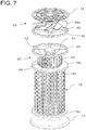
- FIG. 1 is a perspective diagram showing an overall structure of an air-cleaning device 10 according to a first embodiment
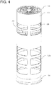
- FIG. 2 is a perspective diagram without a main body casing
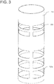
- FIG. 3 is a perspective diagram showing the main body casing. It should be noted here that in each drawing, a filter such as a mesh filter to capture relatively large particles such as dust to be mounted on an opening of the main body casing is omitted.
- the main body casing 12 has a cylindrical shape and the bottom end is mounted on a base 14, while the top end has a lid 16 mounted thereon.
- the base 14 has a trumpet-like shape which broadens downwardly such that the bottom end can be securely placed on a floor or the like. It should be noted that the base 14 can have any shape as long as the base 14 can support the main body.
- a cylindrical filter 18 is mounted on the top end of the base 14.
- the filter 18 includes a cylindrical filter portion 18a through which air is passed and filtered, a lower flange 18b, and an upper flange 18c.
- the lower flange 18b is mounted on the top of the base 14.
- the lower flange 18b may support the bottom end of the main body casing 12.
- the base 14 may have a disk on top thereof and support, by means of the disk, the lower flange 18b of the filter 18 and the lower end portion of the main body casing 12.
- main body casing 12 and the filter 18 have a circular cylindrical shape in the present embodiment, the main body casing 12 and the filter 18 may have another shape such as a polygonal cylindrical shape.
- Both of the lower flange 18b and the upper flange 18c of the filter have a donut-like shape.
- the filter portion 18a is formed from, for example, paper and nonwoven fabric such that the filter portion 18a captures particles on the external surface and obtains cleaned air on the internal side.
- the filter portion 18a is folded to have repeated ridges and grooves in the circumferential direction.
- the bottom end and the top end of the filter portion 18a are respectively air-tightly sealed with the lower flange 18b and the upper flange 18c. It should be noted that although the opening of the lower flange 18b is closed by the disk of the base 14, a disk may be applied in place of the lower flange 18b to close the lower end of the internal space of the filter 18.
- the circumference of the upper flange 18c of the filter 18 is air-tightly sealed with an internal surface of the main body casing 12.
- the circumference of the lower flange 18b or a top disk portion of the base 14 is also air-tightly sealed with the internal surface of the main body casing 12. Therefore, the internal space of the filter portion 18a communicates with space outside the device only through a central opening of the upper flange 18c, and the internal space is partitioned by the outer space of the filter portion 18a by the filter portion 18a.
- the main body casing 12 placed outside the filter portion 18a is provided with two or more opening portions 12a.
- the external space of the filter portion 18a communicates with the external space.
- a filter fan 20 is provided above the upper flange 18c within the main body casing 12.
- a stay 22 including a circumferential ring and a center disk which are connected to each other via two or more radial connecting bars is provided above the filter fan 20.
- the stay 22 is fixed to the main body casing 12 with the circumferential ring fixed to the internal surface of the main body casing 12.
- a motor 24 is mounted downwardly on the center disk of the stay 22.
- Blades 20a of the filter fan 20 are mounted on a rotation axis which extends downwardly from the motor 24. Therefore, the blades 20a rotate along with the rotation of the motor 24, driving the filter fan 20.
- the blades 20a are two or more plate-shaped blades which extend radially.
- the filter fan 20 is an axial flow type fan.
- the filter fan 20 is located where the main body casing 12 has no openings such that the filter fan 20 is placed inside a cylinder of the main body casing 12, it is possible to blow the air inside the main body casing 12 upward or downward by driving the filter fan 20.
- the main body casing 12 has two or more openings above the filter fan 20, that is, above the stay 22 such that the openings serve as vents 26 which enable communication with air outside the device.
- An exhaust fan 28 is provided within the main body casing 12 above the vents 26.
- a stay 30 which has a similar structure to the stay 22 is provided above the vents 26.
- a motor 32 is mounted on a center disk of the stay 30.
- Blades 28a of the exhaust fan 28 are mounted on a rotation axis which extends upwardly from the motor 32. Therefore, the blades 28a rotate along with the rotation of the motor 32, driving the exhaust fan 28.
- the exhaust fan 28 is also an axial flow type fan.
- the main body casing 12 has a top end which is opened and on which a lid 16 is mounted.
- the lid 16 is formed from a circumferential ring, a center disk, two or more intermediate rings, and radial bars connecting these components.
- the lid 16 serves as a guard to prevent users from inserting a hand inside the main body casing 12, with negligible disturbance to the flow of air.
- the filter fan 20 is provided inside the main body casing 12 when the filter fan 20 communicates with the internal space of the filter 18. Accordingly, by discharging air in the internal space of the filter 18 by the filter fan 20, external air is passed and filtered through the filter portion 18a such that the filtered and cleaned air is blown upward of the filter fan 20.
- the air taken in via the vents 26 is blown upward in addition to the air blown by the filter fan 20.
- the filter fan 20 and the exhaust fan 28 blow air upward with the same air blowing capacity, as the air blowing capacity of the filter fan 20 is decreased due to a pressure loss of the filter portion 18a, the exhaust fan 28 is caused to blow air upward while taking external air through the vents 26. Further, even when the air blowing capacity of the exhaust fan 28 is set higher than the filter fan 20, external air is taken from the vents 26 and blown upward.
- the amount of air blown upward of the air-cleaning device can be increased. Accordingly, itispossible to sufficiently circulate air in the room in addition to cleaning the room air with the filter 18. Therefore, by circulating the air, the room air flows such that not only the air around the opening portions 12a but also the air in the whole room can be cleaned by the filter 18.
- the main body casing 12 has a cylindrical shape, the air blowing capacity of the rotating fans can be sufficiently utilized and the installation space can be minimized.
- the air which has passed through the filter 18 is discharged upward.
- some air may also be discharged from the vents 26, most of the air is discharged upward.
- the room air is circulated by the air discharged upward, because the amount of air blown is less than the case with the exhaust fan 28 being driven, the air circulation function is relatively less effective. It should be noted that it is also possible to reduce the amount of air blown by the exhaust fan 28 rather than stopping the exhaust fan 28.
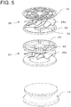
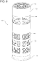
- the second embodiment is shown in FIGs. 6 to 9 .
- a Sirocco fan which is a centrifuge type fan is used as the filter fan 20.
- many plate-shaped blades 40 which are shifted in one direction from the radial direction when seen from the top are arranged in a cylindrical shape.
- the tops of the cylindrically arranged blades 40 are fixed to and closed by an upper disk 42, while the bottoms of the cylindrically arranged blades 40 are connected to a donut-shaped ring 44, which is rotatably supported by an inner circumference of the upper flange 18c of the filter 18.
- the stay 22 is positioned above the filter fan 20.
- a motor 24 is mounted below the stay 22 at the center.
- the upper disk 42 of the filter fan 20 has a concave portion which extends downward at the center.
- the motor 24 is partially received in the concave portion.
- An output shaft of the motor 24 is fixed at the center of the upper disk 42.
- the surrounding space of the cylindrically arranged blades 40 communicates upward inside the main body casing 12, while the bottom end of the cylindrically-arranged blades are closed by the upper flange 18c. Further, the inner space of the filter portion 18a and the inner space of the cylindrically arranged blades 40 communicate with each other through the central opening of the ring 44.
- centrifuge type fan such as a sirocco fan
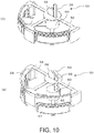
- FIGs. 10 to 12 show an example of a structure in which a shutter 50 is provided with each of the vents 26.
- the shutters 50 which are movable upward, downward, and in a radial direction are provided where the vents 26 of the main body casing 12 shown in FIG. 11 are provided.
- the shutters 50 open and close the vents 26.
- a stay 52 is mounted inside the main body casing 12.
- a motor 54 is mounted at the center of the stay 52.
- the motor 54 rotates a pinion gear 56.
- a rack 58 engages with the pinion gear 56.
- the rack 58 moves upward or downward along with a rotation of the pinion gear 56 in the forward or reverse direction.
- the bottom end of the rack 58 is connected to a cylindrically shaped central member 60.
- a cover member 64 having a shape corresponding to the shape of the vent 26 is mounted on a connection member 62 which extends in a radial direction from the central member 60.
- the cover member 64 is mounted on the connection member 62 such that the cover member 64 is movable in a radial direction.
- Pins 66 which are mounted on both sides of the cover member 64 engage with guide grooves 68 which are provided on both sides of the vents 26 of the main body casing 12 in the circumferential direction.
- the guide grooves 68 are formed such that the pins 66 move toward the inner side of the main body casing 12 along with the downward movement of the pins 66. Accordingly, the cover member 64 moves not only upward and downward but also in a radial direction along with the upward and downward movement of the connection member 62.
- the cover member 64 when the cover member 64 is positioned at the top end, the cover member 64 is positioned at the outer side in a radius direction such that the cover member 64 is pressed into the vent 26 to close the vent 26.
- the cover member 64 when the cover member 64 is moved downward, the cover member 64 is guided by the guide grooves 68 to pull inwards away from the vent 26 such that the cover member 64 is enclosed on the inner side of the main body casing 12.
- the cover member 64 can close or open the vent 26 by forward and reverse rotation of the motor 54.
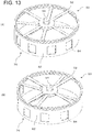
- FIGs. 13 to 15 show another example of the structure of the shutter 50.
- a shutter 50 which moves in circumferential directions is provided inside a portion of the main body casing 12 where the vents 26 are provided, such that the shutter 50 opens or closes the vents 26.
- a stay 52 is provided inside the main body casing 12.
- a rotatable disk 70 which is rotated by the motor 54 in a horizontal plane is provided at the center of the stay 52.
- a pin (not shown) is eccentrically attached on the bottom surface of the rotatable disk 70.
- the pin (not shown) is formed to protrude at an eccentric position on the bottom surface of the rotatable disk 70.
- the pin of the rotatable disk 70 rotates due to the rotation of the motor 54.
- a guide bar 72 is provided beneath the rotatable disk 70.
- the pin of the rotatable disk 70 engages with an elongated hole 74 of the guide bar 72.
- a rotatable cylinder 76 is provided beneath the guide bar 72.
- Two or more connection members 78 directed towards the center, and a center portion 80 which is connected to the inner side of the connection members 78, are formed on the top end of the rotatable cylinder 76.
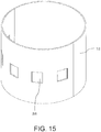
- Two or more windows 84 are provided on a side cylindrical portion 82 of the rotatable cylinder 76.
- Each window 84 has a shape corresponding to the vent 26 of the main body casing 12.
- the vents 26 are opened and closed by the rotation of the rotatable cylinder 76.
- a pin is formed on the bottom surface at one end of the guide bar 72.
- the pin engages with a hole 80a eccentrically disposed on the center portion 80. Accordingly, the pin of the rotatable disk 70 moves within the elongated hole 74.
- the rotation of the guide bar 72 caused by this movement is transformed to a reciprocating rotation movement of the rotatable cylinder 76 (refer to FIGs. 13A and B ).
- Opening and closing of the vents 26 with the rotation of the motor 54 can be enabled by arranging the reciprocating rotation movement amount of the rotatable cylinder 76 to correspond to the opening and closing of the vents 26.
- vents 26 may be provided on the half surface of the main body casing 12 in the circumferential direction. In this way, the direction to take in air through the vents 26 can be limited. It is also possible to provide the vents 26 on the entire surface, and correspondingly provide the windows 84 on the entire surface of the rotatable cylinder 76.
- the shutter 50 may be arranged such that users can switch modes with their hands.
- the main function of the exhaust fan 28 canbe switchedbetween filtering by the filter 18 and air circulation.
- bypasses 56 which communicate between the external space of the filter 18 and the space enclosing the exhaust fan 28 without providing the vents 26, and a shutter 50 which opens and closes the bypass 56.
- the bypass 56 has a pipe shape which extends from the external space of the filter 18 to the upper space of the filter fan 20 .
- a shutter 50 for opening and closing the top opening of the bypass 56 may be provided.
- the shutter 50 has a ring shape and includes openings corresponding in number to the number of bypasses 56, such that the shutter 50 moves in the circumferential direction and thereby opens and closes the top end openings of the bypasses 56.
- bypass 56 can be opened and closed and thereby the air blown by the exhaust fan 28 can be switched between from the internal space and from the external space of the filter 18 (outside the device).
- bypass 56 may extend within the internal space of the filter portion 18a and communicates with the external space via the filter portion 18a.
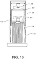
- FIG. 17 shows a further example of a variation.
- only one filter filter fan 20
- An opening 80 which communicates with the external space of the filter portion 18a is provided around the upper flange 18c of the filter 18.
- a shutter 50 to open and close the opening 80 is provided. In this way, the opening 80 can be opened and closed, thereby switching the air blow of the filter fan 20 between from the internal space of the filter 18 and from the external space (outside the device).
- the passage with which the opening 80 communicates may be arranged to extend in the internal space of the filter portion 18a and communicate with the external space via the filter portion 18a.
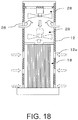
- FIG. 18 shows yet another example.
- the exhaust fan 28 moves up and down.
- the exhaust fan 28 is arranged to be movable to two positions, above and below the vents 26. In this way, when the exhaust fan 28 is positioned below the vents 26, the exhaust fan 28 takes in air from the internal space of the filter 18 and blows the air upward, while when the exhaust fan 28 is positioned above the vents 26, the exhaust fan 28 takes in the external air through the vents 26 and blows the air upward.
- filter fan 20 is omitted in this example, it is also possible to provide the filter fan 20 such that the filter fan 20 takes in air from the internal space of the filter portion 18a, similarly to the above described embodiments.
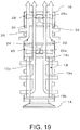
- FIG. 19 shows air flows in a mode in which external air is taken through the vents 26.
- external air By blowing the air in the internal space of the filter 18 upward by the filter fan 20, external air passes through the filter 18 via the opening portions 12a, and thereby the cleaned air is blown upward. Further, as external air is taken in by the exhaust fan 28 through the vents, the air including the external air is blown upward.
- FIG. 20 shows air flows when the vents 26 are closed with the shutter 50. As shown, cleaned air which has passed through the filter 18 is blown upward by the filter fan 20 and the exhaust fan 28. Because the two fans are used to blow the air, the amount of cleaned air passing through the filter 18 can be increased.
- the shutter 50 is structured to open and close the vents provided with the main body casing 12 from inside.
- the bypass 56 is provided inside the main body casing 12, the bypass 56 may also be provided outside the main body casing 12.
- Each mode may be automatically switched by a controller.
- the air circulation power can be increased periodically, such as every 10 minutes, or switches between the air circulation mode and the air clean mode in accordance with output signals from various sensors.
- the air circulation may be performed when the temperature difference between the upper area and the lower area is high, or by detecting the amount of particles in the air, and the air cleaning power can be increased when the detected amount of particles in the air is high.
- DC motors are applied as the motors 24, 32 which drive the filter fan 20 and the exhaust fan 28.
- the DC motors are driven by receiving DC power obtained by converting general utility power of 100VAC to DC.
- AC motors may be used as the motors 24, 32 such that AC power is supplied without conversion.
- a controller including a microcomputer to perform drive control of the motors.
- a single filter fan 20 and a single exhaust fan 28 are provided in the above embodiments, it is also possible to use two or more of either one or both of the filter fan 20 and the exhaust fan 28. In this way, the amount of air blown can be more freely determined.
- 10 air-cleaning device 12 main body casing, 12a opening portions, 14 base, 16 lid, 18 filter, 18a filter portion, 18b lower flange, 18c upper flange, 20 filter fan, 20a, 28a, 40 blades, 22, 30 stay, 24 motor, 26 vents, 28 exhaust fan, 32 motor, 42 upper disk, 44 ring, 50 shutter, 52 stay, and 56 bypass.
Applications Claiming Priority (2)
| Application Number | Priority Date | Filing Date | Title |
|---|---|---|---|
| JP2012088816A JP5864344B2 (ja) | 2012-04-09 | 2012-04-09 | 空気清浄装置 |
| PCT/JP2013/060121 WO2013153995A1 (ja) | 2012-04-09 | 2013-04-02 | 空気清浄装置 |
Publications (3)
| Publication Number | Publication Date |
|---|---|
| EP2837897A1 EP2837897A1 (en) | 2015-02-18 |
| EP2837897A4 EP2837897A4 (en) | 2015-12-02 |
| EP2837897B1 true EP2837897B1 (en) | 2017-03-01 |
Family
ID=49327563
Family Applications (1)
| Application Number | Title | Priority Date | Filing Date |
|---|---|---|---|
| EP13775667.2A Not-in-force EP2837897B1 (en) | 2012-04-09 | 2013-04-02 | Air-cleaning device |
Country Status (6)
| Country | Link |
|---|---|
| EP (1) | EP2837897B1 (ko) |
| JP (1) | JP5864344B2 (ko) |
| KR (1) | KR101705286B1 (ko) |
| CN (1) | CN104204683B (ko) |
| HK (1) | HK1205554A1 (ko) |
| WO (1) | WO2013153995A1 (ko) |
Cited By (3)
| Publication number | Priority date | Publication date | Assignee | Title |
|---|---|---|---|---|
| KR20180044131A (ko) * | 2016-10-21 | 2018-05-02 | 엘지전자 주식회사 | 공기 청정기 |
| CN111412569A (zh) * | 2020-04-01 | 2020-07-14 | 青岛理工大学 | 一种用于建筑物室内空气净化的通风换气装置 |
| US11872513B2 (en) | 2016-08-19 | 2024-01-16 | Samsung Electronics Co., Ltd. | Air cleaner |
Families Citing this family (55)
| Publication number | Priority date | Publication date | Assignee | Title |
|---|---|---|---|---|
| KR101876223B1 (ko) * | 2013-12-27 | 2018-07-10 | 코웨이 주식회사 | 가습형 공기청정기 |
| US20170082305A1 (en) * | 2014-03-17 | 2017-03-23 | Sui Chun Law | An Air Purification Device |
| WO2016004399A1 (en) * | 2014-07-02 | 2016-01-07 | Free Air, Inc. | Room air cleaner systems and methods related thereto |
| JP6327643B2 (ja) * | 2014-07-02 | 2018-05-23 | フルタ電機株式会社 | 微粒子拡散装置 |
| JP2016034602A (ja) * | 2014-08-01 | 2016-03-17 | バルミューダ株式会社 | 空気清浄装置 |
| CN104296259A (zh) * | 2014-10-17 | 2015-01-21 | 太仓市大友空调设备有限公司 | 一种外形可变的多功能净化器 |
| CN104406239A (zh) * | 2014-12-17 | 2015-03-11 | 贵州黔唐电器有限责任公司 | 一种智能多功能空气净化器 |
| KR102396592B1 (ko) * | 2014-12-22 | 2022-05-13 | 코웨이 주식회사 | 급속 순환 공기조화기 |
| KR102359202B1 (ko) * | 2014-12-30 | 2022-02-07 | 삼성전자주식회사 | 공기 청정기 및 공기처리유닛을 구비하는 가전제품 |
| KR101906341B1 (ko) | 2015-04-09 | 2018-10-12 | 코웨이 주식회사 | 공기청정기 |
| CN112503699A (zh) | 2015-08-12 | 2021-03-16 | 豪威株式会社 | 空气净化器 |
| CN105221452A (zh) * | 2015-09-29 | 2016-01-06 | 小米科技有限责任公司 | 空气净化器及其送风装置 |
| CN106813315B (zh) * | 2016-02-26 | 2020-01-07 | Lg电子株式会社 | 空气净化器 |
| JP6700409B2 (ja) * | 2016-02-26 | 2020-05-27 | エルジー エレクトロニクス インコーポレイティド | 空気清浄機 |
| US9827523B2 (en) | 2016-02-26 | 2017-11-28 | Lg Electronics Inc. | Air cleaner |
| US9943794B2 (en) * | 2016-02-26 | 2018-04-17 | Lg Electronics Inc. | Air cleaner |
| CN111765554B (zh) | 2016-02-26 | 2022-02-25 | Lg电子株式会社 | 空气清洁器 |
| CN111156622B (zh) | 2016-02-26 | 2022-04-26 | Lg电子株式会社 | 空气清洁器 |
| WO2017146353A1 (ko) | 2016-02-26 | 2017-08-31 | 엘지전자 주식회사 | 공기 청정기 |
| EP3211338B1 (en) | 2016-02-26 | 2020-03-25 | LG Electronics Inc. | Air cleaner and method for controlling an air cleaner |
| JP6777753B2 (ja) * | 2016-02-26 | 2020-10-28 | エルジー エレクトロニクス インコーポレイティド | 空気清浄機 |
| US10436469B2 (en) | 2016-02-26 | 2019-10-08 | Lg Electronics Inc. | Air cleaner |
| EP3211337B1 (en) | 2016-02-26 | 2020-09-23 | LG Electronics Inc. | Air cleaner |
| EP3211345B1 (en) | 2016-02-26 | 2020-09-16 | Lg Electronics Inc. | Air cleaner |
| KR101897353B1 (ko) * | 2016-02-26 | 2018-10-18 | 엘지전자 주식회사 | 공기 청정기 |
| EP3211347B1 (en) | 2016-02-26 | 2020-12-30 | LG Electronics Inc. | Air cleaner |
| WO2017146354A1 (ko) | 2016-02-26 | 2017-08-31 | 엘지전자 주식회사 | 공기 청정기 |
| EP3211336B1 (en) * | 2016-02-26 | 2020-01-01 | LG Electronics Inc. | Air cleaner |
| AT14956U3 (de) * | 2016-03-03 | 2017-05-15 | Kluge Anton | Säulenförmiger Werbeträger |
| KR20180023235A (ko) * | 2016-08-25 | 2018-03-07 | 엘지전자 주식회사 | 건조기 및 건조기의 제어 방법 |
| CN106225207A (zh) * | 2016-09-18 | 2016-12-14 | 上海唤维信息科技有限公司 | 一种可以控制空间内气流路径的净化系统 |
| EP3306218A1 (en) * | 2016-10-06 | 2018-04-11 | Unilever N.V. | Air purifier |
| CN106287993B (zh) * | 2016-10-24 | 2021-01-26 | 北京小米移动软件有限公司 | 空气净化器及其风道结构 |
| CN108722031B (zh) | 2017-04-24 | 2022-03-08 | 布鲁雅尔公司 | 空气过滤器单元 |
| FR3081729B1 (fr) * | 2018-05-29 | 2022-04-29 | Delta Neu | Dispositif de filtration transportable |
| WO2020079789A1 (ja) * | 2018-10-17 | 2020-04-23 | バルミューダ株式会社 | 空気清浄装置 |
| CN112739957B (zh) * | 2018-10-17 | 2023-02-28 | 博姆达株式会社 | 空气净化装置 |
| KR102129528B1 (ko) * | 2018-12-04 | 2020-07-08 | 주식회사 아지즈 | 공기 조절형 환기 청정기 |
| JP7219409B2 (ja) * | 2019-03-01 | 2023-02-08 | ダイキン工業株式会社 | 空気浄化及び通風装置 |
| JP7174296B2 (ja) * | 2019-03-01 | 2022-11-17 | ダイキン工業株式会社 | 室内空気処理装置及びその作動方法 |
| CN112007451B (zh) * | 2019-05-31 | 2024-03-29 | 大金工业株式会社 | 一种空气净化装置 |
| WO2020183405A1 (en) * | 2019-03-12 | 2020-09-17 | Milind Dhanlal Raut | Centrifugal gas filtration apparatus |
| KR102025931B1 (ko) * | 2019-07-31 | 2019-09-26 | 엘지전자 주식회사 | 공기 청정기 |
| KR102032152B1 (ko) * | 2019-07-31 | 2019-10-15 | 엘지전자 주식회사 | 공기 청정기 |
| JP6724220B1 (ja) * | 2019-08-05 | 2020-07-15 | 株式会社ニトリホールディングス | 空気清浄装置 |
| KR102114666B1 (ko) * | 2019-08-20 | 2020-06-05 | 엘지전자 주식회사 | 공기 청정기 |
| KR102408958B1 (ko) * | 2019-08-20 | 2022-06-14 | 엘지전자 주식회사 | 공기 청정기 |
| KR102152658B1 (ko) * | 2019-08-20 | 2020-09-08 | 엘지전자 주식회사 | 공기 청정기 |
| KR102339347B1 (ko) * | 2019-08-20 | 2021-12-15 | 엘지전자 주식회사 | 공기 청정기 |
| CN110935250A (zh) * | 2019-12-10 | 2020-03-31 | 科沃斯机器人股份有限公司 | 空气净化设备 |
| KR20210083501A (ko) | 2019-12-27 | 2021-07-07 | 삼성전자주식회사 | 공기청정기 |
| KR102259561B1 (ko) * | 2020-11-10 | 2021-06-02 | (주)아지즈 | 환기 겸용 공기청정기 |
| JP2022170496A (ja) * | 2021-04-28 | 2022-11-10 | ブラザー工業株式会社 | 空気清浄機 |
| KR102338380B1 (ko) | 2021-06-02 | 2021-12-13 | 에이치케이시스템 | 습식방식의 다기능 공기 여과기 |
| CN113280456B (zh) * | 2021-06-23 | 2023-11-10 | 合肥河姆博人工环境科技有限公司 | 一种高效导流式等离子空气消毒净化机 |
Family Cites Families (13)
| Publication number | Priority date | Publication date | Assignee | Title |
|---|---|---|---|---|
| JPS60123521U (ja) * | 1984-01-30 | 1985-08-20 | 株式会社日立製作所 | 空気清浄機 |
| JPH03128021A (ja) * | 1989-10-13 | 1991-05-31 | Asmo Co Ltd | 真空掃除機 |
| JPH0621720U (ja) * | 1992-06-26 | 1994-03-22 | ティアック株式会社 | 空気清浄装置 |
| JP2000018657A (ja) | 1998-06-30 | 2000-01-18 | Daikin Ind Ltd | 局所清浄型空気清浄機 |
| JP3929278B2 (ja) * | 2001-10-17 | 2007-06-13 | 株式会社フジシールインターナショナル | フィルム嵌挿装置 |
| US20030150326A1 (en) * | 2002-02-11 | 2003-08-14 | Hp Intellectual Corp. | Multi-stage air cleaner fan system |
| KR200344684Y1 (ko) * | 2003-12-19 | 2004-03-18 | 주식회사 디에스테크 | 급배기를 겸비한 실내공기 청정장치 |
| KR200382452Y1 (ko) * | 2004-12-15 | 2005-04-20 | 주식회사 경남알미늄 | 열교환 기능이 구비된 창틀형 환기 장치 |
| JP4630703B2 (ja) * | 2005-03-29 | 2011-02-09 | シャープ株式会社 | 空気清浄機 |
| JP4720263B2 (ja) * | 2005-04-08 | 2011-07-13 | パナソニック株式会社 | 換気装置 |
| JP4978644B2 (ja) * | 2009-03-06 | 2012-07-18 | 三菱電機株式会社 | 空気処理装置 |
| SG168440A1 (en) * | 2009-07-29 | 2011-02-28 | Newform Techart Pte Ltd | Air filter |
| DE102009053505A1 (de) * | 2009-11-16 | 2011-05-19 | Wu, Fu-Chi, Northridge | Luftreiniger |
-
2012
- 2012-04-09 JP JP2012088816A patent/JP5864344B2/ja not_active Expired - Fee Related
-
2013
- 2013-04-02 EP EP13775667.2A patent/EP2837897B1/en not_active Not-in-force
- 2013-04-02 KR KR1020147031260A patent/KR101705286B1/ko active IP Right Grant
- 2013-04-02 CN CN201380019070.5A patent/CN104204683B/zh not_active Expired - Fee Related
- 2013-04-02 WO PCT/JP2013/060121 patent/WO2013153995A1/ja active Application Filing
-
2015
- 2015-06-25 HK HK15106068.7A patent/HK1205554A1/xx not_active IP Right Cessation
Non-Patent Citations (1)
| Title |
|---|
| None * |
Cited By (4)
| Publication number | Priority date | Publication date | Assignee | Title |
|---|---|---|---|---|
| US11872513B2 (en) | 2016-08-19 | 2024-01-16 | Samsung Electronics Co., Ltd. | Air cleaner |
| KR20180044131A (ko) * | 2016-10-21 | 2018-05-02 | 엘지전자 주식회사 | 공기 청정기 |
| KR101854998B1 (ko) * | 2016-10-21 | 2018-06-20 | 엘지전자 주식회사 | 공기 청정기 |
| CN111412569A (zh) * | 2020-04-01 | 2020-07-14 | 青岛理工大学 | 一种用于建筑物室内空气净化的通风换气装置 |
Also Published As
| Publication number | Publication date |
|---|---|
| CN104204683A (zh) | 2014-12-10 |
| JP5864344B2 (ja) | 2016-02-17 |
| CN104204683B (zh) | 2017-06-20 |
| KR20150005594A (ko) | 2015-01-14 |
| EP2837897A1 (en) | 2015-02-18 |
| WO2013153995A1 (ja) | 2013-10-17 |
| HK1205554A1 (en) | 2015-12-18 |
| KR101705286B1 (ko) | 2017-02-09 |
| EP2837897A4 (en) | 2015-12-02 |
| JP2013217580A (ja) | 2013-10-24 |
Similar Documents
| Publication | Publication Date | Title |
|---|---|---|
| EP2837897B1 (en) | Air-cleaning device | |
| US10888811B2 (en) | Air purifying unit and air cleaning/ventilation device comprising same | |
| EP3330624B1 (en) | Slim-type air processing device | |
| RU2676381C1 (ru) | Пылесборник для вакуумного пылесоса | |
| EP1997414B1 (en) | Cyclone dust-separating apparatus of vacuum cleaner | |
| CN109996593B (zh) | 能够调节风向的空气净化器 | |
| CN108291728B (zh) | 空气净化器 | |
| KR20080013175A (ko) | 공기청정기와 그 제어방법 | |
| KR101787188B1 (ko) | 공기 정화 장치 | |
| CN108223408B (zh) | 可移动烟机 | |
| CN105042713B (zh) | 一种出风口外接导流口的空气净化器 | |
| KR20170090256A (ko) | 흡기유닛 및 이를 포함하는 환기장치 | |
| KR101774103B1 (ko) | 공기 정화 장치 | |
| CN205700006U (zh) | 一种气体处理装置 | |
| CN110292793A (zh) | 一种自清洗除油过滤器 | |
| KR20220115903A (ko) | 공기청정기 | |
| KR20200000159U (ko) | 정화 기능을 구비한 기류팬 | |
| CN208139450U (zh) | 一种具有双风道离心风机的空气净化装置 | |
| CN209101494U (zh) | 新风设备及其系统 | |
| CN106889940A (zh) | 吸尘器、尤其手持式电池吸尘器 | |
| KR101774173B1 (ko) | 공기 정화 장치 | |
| KR20220021764A (ko) | 공기청정기 | |
| CN216572163U (zh) | 除尘器 | |
| KR200376822Y1 (ko) | 공기정화기 | |
| CN218936581U (zh) | 一种空气净化器 |
Legal Events
| Date | Code | Title | Description |
|---|---|---|---|
| PUAI | Public reference made under article 153(3) epc to a published international application that has entered the european phase |
Free format text: ORIGINAL CODE: 0009012 |
|
| 17P | Request for examination filed |
Effective date: 20141001 |
|
| AK | Designated contracting states |
Kind code of ref document: A1 Designated state(s): AL AT BE BG CH CY CZ DE DK EE ES FI FR GB GR HR HU IE IS IT LI LT LU LV MC MK MT NL NO PL PT RO RS SE SI SK SM TR |
|
| AX | Request for extension of the european patent |
Extension state: BA ME |
|
| DAX | Request for extension of the european patent (deleted) | ||
| RA4 | Supplementary search report drawn up and despatched (corrected) |
Effective date: 20151103 |
|
| RIC1 | Information provided on ipc code assigned before grant |
Ipc: B01D 46/24 20060101ALI20151028BHEP Ipc: F24F 7/00 20060101AFI20151028BHEP Ipc: B01D 46/00 20060101ALI20151028BHEP Ipc: F24F 13/20 20060101ALI20151028BHEP Ipc: F24F 13/28 20060101ALI20151028BHEP Ipc: F24F 3/16 20060101ALI20151028BHEP |
|
| REG | Reference to a national code |
Ref country code: HK Ref legal event code: DE Ref document number: 1205554 Country of ref document: HK |
|
| GRAP | Despatch of communication of intention to grant a patent |
Free format text: ORIGINAL CODE: EPIDOSNIGR1 |
|
| INTG | Intention to grant announced |
Effective date: 20161026 |
|
| GRAS | Grant fee paid |
Free format text: ORIGINAL CODE: EPIDOSNIGR3 |
|
| GRAA | (expected) grant |
Free format text: ORIGINAL CODE: 0009210 |
|
| AK | Designated contracting states |
Kind code of ref document: B1 Designated state(s): AL AT BE BG CH CY CZ DE DK EE ES FI FR GB GR HR HU IE IS IT LI LT LU LV MC MK MT NL NO PL PT RO RS SE SI SK SM TR |
|
| REG | Reference to a national code |
Ref country code: GB Ref legal event code: FG4D |
|
| REG | Reference to a national code |
Ref country code: CH Ref legal event code: EP Ref country code: AT Ref legal event code: REF Ref document number: 871849 Country of ref document: AT Kind code of ref document: T Effective date: 20170315 |
|
| REG | Reference to a national code |
Ref country code: IE Ref legal event code: FG4D |
|
| REG | Reference to a national code |
Ref country code: DE Ref legal event code: R096 Ref document number: 602013018043 Country of ref document: DE |
|
| REG | Reference to a national code |
Ref country code: NL Ref legal event code: MP Effective date: 20170301 |
|
| REG | Reference to a national code |
Ref country code: LT Ref legal event code: MG4D |
|
| REG | Reference to a national code |
Ref country code: AT Ref legal event code: MK05 Ref document number: 871849 Country of ref document: AT Kind code of ref document: T Effective date: 20170301 |
|
| PG25 | Lapsed in a contracting state [announced via postgrant information from national office to epo] |
Ref country code: HR Free format text: LAPSE BECAUSE OF FAILURE TO SUBMIT A TRANSLATION OF THE DESCRIPTION OR TO PAY THE FEE WITHIN THE PRESCRIBED TIME-LIMIT Effective date: 20170301 Ref country code: GR Free format text: LAPSE BECAUSE OF FAILURE TO SUBMIT A TRANSLATION OF THE DESCRIPTION OR TO PAY THE FEE WITHIN THE PRESCRIBED TIME-LIMIT Effective date: 20170602 Ref country code: LT Free format text: LAPSE BECAUSE OF FAILURE TO SUBMIT A TRANSLATION OF THE DESCRIPTION OR TO PAY THE FEE WITHIN THE PRESCRIBED TIME-LIMIT Effective date: 20170301 Ref country code: FI Free format text: LAPSE BECAUSE OF FAILURE TO SUBMIT A TRANSLATION OF THE DESCRIPTION OR TO PAY THE FEE WITHIN THE PRESCRIBED TIME-LIMIT Effective date: 20170301 Ref country code: NO Free format text: LAPSE BECAUSE OF FAILURE TO SUBMIT A TRANSLATION OF THE DESCRIPTION OR TO PAY THE FEE WITHIN THE PRESCRIBED TIME-LIMIT Effective date: 20170601 |
|
| PGFP | Annual fee paid to national office [announced via postgrant information from national office to epo] |
Ref country code: DE Payment date: 20170216 Year of fee payment: 5 |
|
| PG25 | Lapsed in a contracting state [announced via postgrant information from national office to epo] |
Ref country code: LV Free format text: LAPSE BECAUSE OF FAILURE TO SUBMIT A TRANSLATION OF THE DESCRIPTION OR TO PAY THE FEE WITHIN THE PRESCRIBED TIME-LIMIT Effective date: 20170301 Ref country code: AT Free format text: LAPSE BECAUSE OF FAILURE TO SUBMIT A TRANSLATION OF THE DESCRIPTION OR TO PAY THE FEE WITHIN THE PRESCRIBED TIME-LIMIT Effective date: 20170301 Ref country code: RS Free format text: LAPSE BECAUSE OF FAILURE TO SUBMIT A TRANSLATION OF THE DESCRIPTION OR TO PAY THE FEE WITHIN THE PRESCRIBED TIME-LIMIT Effective date: 20170301 Ref country code: SE Free format text: LAPSE BECAUSE OF FAILURE TO SUBMIT A TRANSLATION OF THE DESCRIPTION OR TO PAY THE FEE WITHIN THE PRESCRIBED TIME-LIMIT Effective date: 20170301 Ref country code: ES Free format text: LAPSE BECAUSE OF FAILURE TO SUBMIT A TRANSLATION OF THE DESCRIPTION OR TO PAY THE FEE WITHIN THE PRESCRIBED TIME-LIMIT Effective date: 20170301 Ref country code: BG Free format text: LAPSE BECAUSE OF FAILURE TO SUBMIT A TRANSLATION OF THE DESCRIPTION OR TO PAY THE FEE WITHIN THE PRESCRIBED TIME-LIMIT Effective date: 20170601 |
|
| PG25 | Lapsed in a contracting state [announced via postgrant information from national office to epo] |
Ref country code: NL Free format text: LAPSE BECAUSE OF FAILURE TO SUBMIT A TRANSLATION OF THE DESCRIPTION OR TO PAY THE FEE WITHIN THE PRESCRIBED TIME-LIMIT Effective date: 20170301 |
|
| PG25 | Lapsed in a contracting state [announced via postgrant information from national office to epo] |
Ref country code: CZ Free format text: LAPSE BECAUSE OF FAILURE TO SUBMIT A TRANSLATION OF THE DESCRIPTION OR TO PAY THE FEE WITHIN THE PRESCRIBED TIME-LIMIT Effective date: 20170301 Ref country code: RO Free format text: LAPSE BECAUSE OF FAILURE TO SUBMIT A TRANSLATION OF THE DESCRIPTION OR TO PAY THE FEE WITHIN THE PRESCRIBED TIME-LIMIT Effective date: 20170301 Ref country code: SK Free format text: LAPSE BECAUSE OF FAILURE TO SUBMIT A TRANSLATION OF THE DESCRIPTION OR TO PAY THE FEE WITHIN THE PRESCRIBED TIME-LIMIT Effective date: 20170301 Ref country code: EE Free format text: LAPSE BECAUSE OF FAILURE TO SUBMIT A TRANSLATION OF THE DESCRIPTION OR TO PAY THE FEE WITHIN THE PRESCRIBED TIME-LIMIT Effective date: 20170301 Ref country code: IT Free format text: LAPSE BECAUSE OF FAILURE TO SUBMIT A TRANSLATION OF THE DESCRIPTION OR TO PAY THE FEE WITHIN THE PRESCRIBED TIME-LIMIT Effective date: 20170301 |
|
| PG25 | Lapsed in a contracting state [announced via postgrant information from national office to epo] |
Ref country code: SM Free format text: LAPSE BECAUSE OF FAILURE TO SUBMIT A TRANSLATION OF THE DESCRIPTION OR TO PAY THE FEE WITHIN THE PRESCRIBED TIME-LIMIT Effective date: 20170301 Ref country code: IS Free format text: LAPSE BECAUSE OF FAILURE TO SUBMIT A TRANSLATION OF THE DESCRIPTION OR TO PAY THE FEE WITHIN THE PRESCRIBED TIME-LIMIT Effective date: 20170701 Ref country code: PT Free format text: LAPSE BECAUSE OF FAILURE TO SUBMIT A TRANSLATION OF THE DESCRIPTION OR TO PAY THE FEE WITHIN THE PRESCRIBED TIME-LIMIT Effective date: 20170703 Ref country code: PL Free format text: LAPSE BECAUSE OF FAILURE TO SUBMIT A TRANSLATION OF THE DESCRIPTION OR TO PAY THE FEE WITHIN THE PRESCRIBED TIME-LIMIT Effective date: 20170301 |
|
| REG | Reference to a national code |
Ref country code: CH Ref legal event code: PL |
|
| REG | Reference to a national code |
Ref country code: DE Ref legal event code: R097 Ref document number: 602013018043 Country of ref document: DE |
|
| REG | Reference to a national code |
Ref country code: HK Ref legal event code: GR Ref document number: 1205554 Country of ref document: HK |
|
| PLBE | No opposition filed within time limit |
Free format text: ORIGINAL CODE: 0009261 |
|
| STAA | Information on the status of an ep patent application or granted ep patent |
Free format text: STATUS: NO OPPOSITION FILED WITHIN TIME LIMIT |
|
| REG | Reference to a national code |
Ref country code: IE Ref legal event code: MM4A |
|
| REG | Reference to a national code |
Ref country code: FR Ref legal event code: ST Effective date: 20171229 |
|
| PG25 | Lapsed in a contracting state [announced via postgrant information from national office to epo] |
Ref country code: FR Free format text: LAPSE BECAUSE OF NON-PAYMENT OF DUE FEES Effective date: 20170502 Ref country code: DK Free format text: LAPSE BECAUSE OF FAILURE TO SUBMIT A TRANSLATION OF THE DESCRIPTION OR TO PAY THE FEE WITHIN THE PRESCRIBED TIME-LIMIT Effective date: 20170301 Ref country code: MC Free format text: LAPSE BECAUSE OF FAILURE TO SUBMIT A TRANSLATION OF THE DESCRIPTION OR TO PAY THE FEE WITHIN THE PRESCRIBED TIME-LIMIT Effective date: 20170301 |
|
| 26N | No opposition filed |
Effective date: 20171204 |
|
| GBPC | Gb: european patent ceased through non-payment of renewal fee |
Effective date: 20170601 |
|
| PG25 | Lapsed in a contracting state [announced via postgrant information from national office to epo] |
Ref country code: SI Free format text: LAPSE BECAUSE OF FAILURE TO SUBMIT A TRANSLATION OF THE DESCRIPTION OR TO PAY THE FEE WITHIN THE PRESCRIBED TIME-LIMIT Effective date: 20170301 Ref country code: LI Free format text: LAPSE BECAUSE OF NON-PAYMENT OF DUE FEES Effective date: 20170430 Ref country code: LU Free format text: LAPSE BECAUSE OF NON-PAYMENT OF DUE FEES Effective date: 20170402 Ref country code: CH Free format text: LAPSE BECAUSE OF NON-PAYMENT OF DUE FEES Effective date: 20170430 |
|
| REG | Reference to a national code |
Ref country code: BE Ref legal event code: MM Effective date: 20170430 |
|
| PG25 | Lapsed in a contracting state [announced via postgrant information from national office to epo] |
Ref country code: IE Free format text: LAPSE BECAUSE OF NON-PAYMENT OF DUE FEES Effective date: 20170402 Ref country code: GB Free format text: LAPSE BECAUSE OF NON-PAYMENT OF DUE FEES Effective date: 20170601 |
|
| PG25 | Lapsed in a contracting state [announced via postgrant information from national office to epo] |
Ref country code: BE Free format text: LAPSE BECAUSE OF NON-PAYMENT OF DUE FEES Effective date: 20170430 |
|
| PG25 | Lapsed in a contracting state [announced via postgrant information from national office to epo] |
Ref country code: MT Free format text: LAPSE BECAUSE OF NON-PAYMENT OF DUE FEES Effective date: 20170402 |
|
| REG | Reference to a national code |
Ref country code: DE Ref legal event code: R119 Ref document number: 602013018043 Country of ref document: DE |
|
| PG25 | Lapsed in a contracting state [announced via postgrant information from national office to epo] |
Ref country code: DE Free format text: LAPSE BECAUSE OF NON-PAYMENT OF DUE FEES Effective date: 20181101 |
|
| PG25 | Lapsed in a contracting state [announced via postgrant information from national office to epo] |
Ref country code: HU Free format text: LAPSE BECAUSE OF FAILURE TO SUBMIT A TRANSLATION OF THE DESCRIPTION OR TO PAY THE FEE WITHIN THE PRESCRIBED TIME-LIMIT; INVALID AB INITIO Effective date: 20130402 |
|
| PG25 | Lapsed in a contracting state [announced via postgrant information from national office to epo] |
Ref country code: CY Free format text: LAPSE BECAUSE OF FAILURE TO SUBMIT A TRANSLATION OF THE DESCRIPTION OR TO PAY THE FEE WITHIN THE PRESCRIBED TIME-LIMIT Effective date: 20170301 |
|
| PG25 | Lapsed in a contracting state [announced via postgrant information from national office to epo] |
Ref country code: MK Free format text: LAPSE BECAUSE OF FAILURE TO SUBMIT A TRANSLATION OF THE DESCRIPTION OR TO PAY THE FEE WITHIN THE PRESCRIBED TIME-LIMIT Effective date: 20170301 |
|
| PG25 | Lapsed in a contracting state [announced via postgrant information from national office to epo] |
Ref country code: TR Free format text: LAPSE BECAUSE OF FAILURE TO SUBMIT A TRANSLATION OF THE DESCRIPTION OR TO PAY THE FEE WITHIN THE PRESCRIBED TIME-LIMIT Effective date: 20170301 |
|
| PG25 | Lapsed in a contracting state [announced via postgrant information from national office to epo] |
Ref country code: AL Free format text: LAPSE BECAUSE OF FAILURE TO SUBMIT A TRANSLATION OF THE DESCRIPTION OR TO PAY THE FEE WITHIN THE PRESCRIBED TIME-LIMIT Effective date: 20170301 |