EP2835239A1 - Procédé de fabrication d'un corps en nid d'abeille en céramique - Google Patents
Procédé de fabrication d'un corps en nid d'abeille en céramique Download PDFInfo
- Publication number
- EP2835239A1 EP2835239A1 EP20130772540 EP13772540A EP2835239A1 EP 2835239 A1 EP2835239 A1 EP 2835239A1 EP 20130772540 EP20130772540 EP 20130772540 EP 13772540 A EP13772540 A EP 13772540A EP 2835239 A1 EP2835239 A1 EP 2835239A1
- Authority
- EP
- European Patent Office
- Prior art keywords
- ceramic honeycomb
- honeycomb body
- machining
- peripheral portion
- end surface
- Prior art date
- Legal status (The legal status is an assumption and is not a legal conclusion. Google has not performed a legal analysis and makes no representation as to the accuracy of the status listed.)
- Granted
Links
Images


Classifications
-
- B—PERFORMING OPERATIONS; TRANSPORTING
- B28—WORKING CEMENT, CLAY, OR STONE
- B28B—SHAPING CLAY OR OTHER CERAMIC COMPOSITIONS; SHAPING SLAG; SHAPING MIXTURES CONTAINING CEMENTITIOUS MATERIAL, e.g. PLASTER
- B28B11/00—Apparatus or processes for treating or working the shaped or preshaped articles
- B28B11/12—Apparatus or processes for treating or working the shaped or preshaped articles for removing parts of the articles by cutting
-
- B—PERFORMING OPERATIONS; TRANSPORTING
- B23—MACHINE TOOLS; METAL-WORKING NOT OTHERWISE PROVIDED FOR
- B23B—TURNING; BORING
- B23B5/00—Turning-machines or devices specially adapted for particular work; Accessories specially adapted therefor
- B23B5/08—Turning-machines or devices specially adapted for particular work; Accessories specially adapted therefor for turning axles, bars, rods, tubes, rolls, i.e. shaft-turning lathes, roll lathes; Centreless turning
- B23B5/12—Turning-machines or devices specially adapted for particular work; Accessories specially adapted therefor for turning axles, bars, rods, tubes, rolls, i.e. shaft-turning lathes, roll lathes; Centreless turning for peeling bars or tubes by making use of cutting bits arranged around the workpiece
-
- B—PERFORMING OPERATIONS; TRANSPORTING
- B23—MACHINE TOOLS; METAL-WORKING NOT OTHERWISE PROVIDED FOR
- B23B—TURNING; BORING
- B23B23/00—Tailstocks; Centres
-
- B—PERFORMING OPERATIONS; TRANSPORTING
- B23—MACHINE TOOLS; METAL-WORKING NOT OTHERWISE PROVIDED FOR
- B23B—TURNING; BORING
- B23B33/00—Drivers; Driving centres, Nose clutches, e.g. lathe dogs
-
- B—PERFORMING OPERATIONS; TRANSPORTING
- B28—WORKING CEMENT, CLAY, OR STONE
- B28B—SHAPING CLAY OR OTHER CERAMIC COMPOSITIONS; SHAPING SLAG; SHAPING MIXTURES CONTAINING CEMENTITIOUS MATERIAL, e.g. PLASTER
- B28B11/00—Apparatus or processes for treating or working the shaped or preshaped articles
- B28B11/04—Apparatus or processes for treating or working the shaped or preshaped articles for coating or applying engobing layers
-
- B—PERFORMING OPERATIONS; TRANSPORTING
- B28—WORKING CEMENT, CLAY, OR STONE
- B28D—WORKING STONE OR STONE-LIKE MATERIALS
- B28D1/00—Working stone or stone-like materials, e.g. brick, concrete or glass, not provided for elsewhere; Machines, devices, tools therefor
- B28D1/16—Working stone or stone-like materials, e.g. brick, concrete or glass, not provided for elsewhere; Machines, devices, tools therefor by turning
-
- C—CHEMISTRY; METALLURGY
- C04—CEMENTS; CONCRETE; ARTIFICIAL STONE; CERAMICS; REFRACTORIES
- C04B—LIME, MAGNESIA; SLAG; CEMENTS; COMPOSITIONS THEREOF, e.g. MORTARS, CONCRETE OR LIKE BUILDING MATERIALS; ARTIFICIAL STONE; CERAMICS; REFRACTORIES; TREATMENT OF NATURAL STONE
- C04B41/00—After-treatment of mortars, concrete, artificial stone or ceramics; Treatment of natural stone
- C04B41/009—After-treatment of mortars, concrete, artificial stone or ceramics; Treatment of natural stone characterised by the material treated
-
- C—CHEMISTRY; METALLURGY
- C04—CEMENTS; CONCRETE; ARTIFICIAL STONE; CERAMICS; REFRACTORIES
- C04B—LIME, MAGNESIA; SLAG; CEMENTS; COMPOSITIONS THEREOF, e.g. MORTARS, CONCRETE OR LIKE BUILDING MATERIALS; ARTIFICIAL STONE; CERAMICS; REFRACTORIES; TREATMENT OF NATURAL STONE
- C04B41/00—After-treatment of mortars, concrete, artificial stone or ceramics; Treatment of natural stone
- C04B41/45—Coating or impregnating, e.g. injection in masonry, partial coating of green or fired ceramics, organic coating compositions for adhering together two concrete elements
- C04B41/50—Coating or impregnating, e.g. injection in masonry, partial coating of green or fired ceramics, organic coating compositions for adhering together two concrete elements with inorganic materials
- C04B41/5076—Coating or impregnating, e.g. injection in masonry, partial coating of green or fired ceramics, organic coating compositions for adhering together two concrete elements with inorganic materials with masses bonded by inorganic cements
- C04B41/508—Aluminous cements
-
- C—CHEMISTRY; METALLURGY
- C04—CEMENTS; CONCRETE; ARTIFICIAL STONE; CERAMICS; REFRACTORIES
- C04B—LIME, MAGNESIA; SLAG; CEMENTS; COMPOSITIONS THEREOF, e.g. MORTARS, CONCRETE OR LIKE BUILDING MATERIALS; ARTIFICIAL STONE; CERAMICS; REFRACTORIES; TREATMENT OF NATURAL STONE
- C04B41/00—After-treatment of mortars, concrete, artificial stone or ceramics; Treatment of natural stone
- C04B41/45—Coating or impregnating, e.g. injection in masonry, partial coating of green or fired ceramics, organic coating compositions for adhering together two concrete elements
- C04B41/50—Coating or impregnating, e.g. injection in masonry, partial coating of green or fired ceramics, organic coating compositions for adhering together two concrete elements with inorganic materials
- C04B41/5076—Coating or impregnating, e.g. injection in masonry, partial coating of green or fired ceramics, organic coating compositions for adhering together two concrete elements with inorganic materials with masses bonded by inorganic cements
- C04B41/5089—Silica sols, alkyl, ammonium or alkali metal silicate cements
-
- C—CHEMISTRY; METALLURGY
- C04—CEMENTS; CONCRETE; ARTIFICIAL STONE; CERAMICS; REFRACTORIES
- C04B—LIME, MAGNESIA; SLAG; CEMENTS; COMPOSITIONS THEREOF, e.g. MORTARS, CONCRETE OR LIKE BUILDING MATERIALS; ARTIFICIAL STONE; CERAMICS; REFRACTORIES; TREATMENT OF NATURAL STONE
- C04B41/00—After-treatment of mortars, concrete, artificial stone or ceramics; Treatment of natural stone
- C04B41/80—After-treatment of mortars, concrete, artificial stone or ceramics; Treatment of natural stone of only ceramics
- C04B41/81—Coating or impregnation
- C04B41/85—Coating or impregnation with inorganic materials
-
- C—CHEMISTRY; METALLURGY
- C04—CEMENTS; CONCRETE; ARTIFICIAL STONE; CERAMICS; REFRACTORIES
- C04B—LIME, MAGNESIA; SLAG; CEMENTS; COMPOSITIONS THEREOF, e.g. MORTARS, CONCRETE OR LIKE BUILDING MATERIALS; ARTIFICIAL STONE; CERAMICS; REFRACTORIES; TREATMENT OF NATURAL STONE
- C04B41/00—After-treatment of mortars, concrete, artificial stone or ceramics; Treatment of natural stone
- C04B41/80—After-treatment of mortars, concrete, artificial stone or ceramics; Treatment of natural stone of only ceramics
- C04B41/91—After-treatment of mortars, concrete, artificial stone or ceramics; Treatment of natural stone of only ceramics involving the removal of part of the materials of the treated articles, e.g. etching
-
- B—PERFORMING OPERATIONS; TRANSPORTING
- B23—MACHINE TOOLS; METAL-WORKING NOT OTHERWISE PROVIDED FOR
- B23B—TURNING; BORING
- B23B2226/00—Materials of tools or workpieces not comprising a metal
- B23B2226/18—Ceramic
-
- C—CHEMISTRY; METALLURGY
- C04—CEMENTS; CONCRETE; ARTIFICIAL STONE; CERAMICS; REFRACTORIES
- C04B—LIME, MAGNESIA; SLAG; CEMENTS; COMPOSITIONS THEREOF, e.g. MORTARS, CONCRETE OR LIKE BUILDING MATERIALS; ARTIFICIAL STONE; CERAMICS; REFRACTORIES; TREATMENT OF NATURAL STONE
- C04B2111/00—Mortars, concrete or artificial stone or mixtures to prepare them, characterised by specific function, property or use
- C04B2111/00474—Uses not provided for elsewhere in C04B2111/00
- C04B2111/00793—Uses not provided for elsewhere in C04B2111/00 as filters or diaphragms
-
- C—CHEMISTRY; METALLURGY
- C04—CEMENTS; CONCRETE; ARTIFICIAL STONE; CERAMICS; REFRACTORIES
- C04B—LIME, MAGNESIA; SLAG; CEMENTS; COMPOSITIONS THEREOF, e.g. MORTARS, CONCRETE OR LIKE BUILDING MATERIALS; ARTIFICIAL STONE; CERAMICS; REFRACTORIES; TREATMENT OF NATURAL STONE
- C04B2111/00—Mortars, concrete or artificial stone or mixtures to prepare them, characterised by specific function, property or use
- C04B2111/00474—Uses not provided for elsewhere in C04B2111/00
- C04B2111/0081—Uses not provided for elsewhere in C04B2111/00 as catalysts or catalyst carriers
-
- Y—GENERAL TAGGING OF NEW TECHNOLOGICAL DEVELOPMENTS; GENERAL TAGGING OF CROSS-SECTIONAL TECHNOLOGIES SPANNING OVER SEVERAL SECTIONS OF THE IPC; TECHNICAL SUBJECTS COVERED BY FORMER USPC CROSS-REFERENCE ART COLLECTIONS [XRACs] AND DIGESTS
- Y10—TECHNICAL SUBJECTS COVERED BY FORMER USPC
- Y10T—TECHNICAL SUBJECTS COVERED BY FORMER US CLASSIFICATION
- Y10T29/00—Metal working
- Y10T29/49—Method of mechanical manufacture
- Y10T29/49616—Structural member making
- Y10T29/4962—Grille making
-
- Y—GENERAL TAGGING OF NEW TECHNOLOGICAL DEVELOPMENTS; GENERAL TAGGING OF CROSS-SECTIONAL TECHNOLOGIES SPANNING OVER SEVERAL SECTIONS OF THE IPC; TECHNICAL SUBJECTS COVERED BY FORMER USPC CROSS-REFERENCE ART COLLECTIONS [XRACs] AND DIGESTS
- Y10—TECHNICAL SUBJECTS COVERED BY FORMER USPC
- Y10T—TECHNICAL SUBJECTS COVERED BY FORMER US CLASSIFICATION
- Y10T82/00—Turning
- Y10T82/10—Process of turning
Definitions
- the present invention relates to a method for producing a ceramic honeycomb body for constituting ceramic honeycomb structures or ceramic honeycomb filters used for removing toxic materials from an exhaust gas discharged from automobile engines, etc.
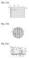
- a ceramic honeycomb structure 1 as shown in Fig. 1 is used for an exhaust-gas-cleaning catalyst converter comprising a ceramic honeycomb structure, and a particulate-matter-capturing filter.
- the production of a ceramic honeycomb structure comprises the steps of, for example, mixing and blending ceramic powder such as a cordierite-forming material powder with a binder, a pore-forming material, water, etc. to form a moldable ceramic material; extruding the moldable ceramic material through a extrusion-molding die to form a ceramic honeycomb green body having a honeycomb structure comprising a peripheral wall 11 and flowing paths 4 partitioned by cell walls 3; removing water, etc. from the ceramic honeycomb green body; and sintering it in a furnace.
- a molding aid such as a binder, etc. are removed from the green body, providing a ceramic honeycomb structure having predetermined shape and strength and comprising cell walls with fine pores.
- a green body When as large a ceramic honeycomb structure as having an outer diameter of 150 mm or more and a length of 150 mm or more, or a ceramic honeycomb structure comprising cell walls as thin as 0.2 mm or less is produced, a green body does not have sufficient strength, suffering such problems as the deformation of cell walls near a peripheral layer by its own weight when extruded, and failure to obtaining predetermined strength after sintering.
- JP 2004-148791 A discloses a method for producing a ceramic honeycomb structure by the extrusion of a moldable ceramic material, drying and sintering, comprising the steps of removing a peripheral portion of a ceramic honeycomb body by machining after drying, and coating the peripheral surface with a peripheral layer after sintering.
- JP 2004-148791 A describes that the removal of the peripheral portion by machining is conducted by cutting a dried ceramic honeycomb body fixed to a lathe and rotated at 260 rpm with a cemented carbide bite attached to a carrier at a cutting depth of 5 mm and a feed speed of 1.0 mm/second.
- JP 2004-148791 A describes that the machined ceramic honeycomb body has part of cell walls removed to have grooves open on the peripheral surface, so that cracking does not easily proceed during sintering, and that the peripheral layer is not easily peeled from the honeycomb body, resulting in a honeycomb structure having excellent isostatic strength.
- WO2004/078674 A describes a method for producing a ceramic honeycomb structure by the extrusion of a moldable ceramic material, drying and sintering, comprising the steps of drying a green body, alternately plugging one or the other end portion of each cell open on both end surfaces, removing a peripheral portion (peripheral wall and part of cell walls) by machining with a lathe after sintering, and coating the exposed peripheral surface with a peripheral layer.
- WO2004/078674 A describes that a ceramic honeycomb structure thus obtained is free from breakage when canned, and has excellent heat shock resistance.
- JP 2004-148791 A and WO 2004/078674 A describe a step of machining a peripheral portion of a ceramic honeycomb body by a lathe in the production of a ceramic honeycomb structure, they fail to describe detailed machining conditions.
- a peripheral portion of a cylindrical body such as a ceramic honeycomb body is machined, one end portion 19 of a ceramic honeycomb body 10 is fixed to a lathe 90 with a chuck 91 as shown in Fig. 12(a) , a peripheral portion 12 (hatched portion) is removed, and the end portion 19 not machined because of chucking is then cut off at a position A shown by the dotted line in Fig. 12(b) , providing a ceramic honeycomb body of a predetermined length.
- a ceramic honeycomb body used for cleaning an exhaust gas generally has a cell structure constituted by porous cell walls, with low strength because of high porosity. Accordingly, when its peripheral portion is removed by machining in a chucked state, a chucked portion of the ceramic honeycomb body may be broken by a load during machining. Particularly a high-porosity honeycomb body is more easily broken because of lower strength. Also, when the ceramic honeycomb body is sintered, its strength is reduced because a binder is removed from the green body, breakage occurs more easily. Further, when the ceramic honeycomb body is chucked for machining, a portion not machined because of chucking should be cut off, resulting in a low yield.
- an object of the present invention is to provide a method for producing a ceramic honeycomb body with a high yield, suffering little breakage during removing its peripheral portion by machining with a lathe.
- the inventors have found that when a peripheral portion of a rotating ceramic honeycomb body is removed by machining, with both end surfaces of the ceramic honeycomb body held under pressure by abutting portions of fixing jigs, whose outer shapes are smaller than those of the end surfaces, the ceramic honeycomb body are unlikely broken, and the peripheral portion is removed from the ceramic honeycomb body by machining at a high yield.
- the present invention has been completed based on such finding.
- the method of the present invention for producing a ceramic honeycomb body having large numbers of longitudinal cells partitioned by cell walls, with its peripheral portion removed by machining comprises rotatably holding the ceramic honeycomb body on a main axis of a lathe, and rotating the ceramic honeycomb body around the main axis, to remove a peripheral portion of the ceramic honeycomb body by machining with a tool; the lathe comprising a first fixing jig on the main axis, and a second fixing jig substantially opposing the first fixing jig; each of the first and second fixing jigs having an abutting end portion opposing each other, the abutting end portion having a smaller outer shape than that of the end surface of the ceramic honeycomb body, and the abutting portion having a substantially flat abutting end surface perpendicular to the main axis; and the ceramic honeycomb body being held by pressing the abutting surfaces of the first and second fixing jigs to both end surfaces of the ceramic honeycomb body, such
- the abutting portions are preferably detachable from the fixing jigs.
- the abutting portions are preferably made of a nonmetallic material.
- the area ratio of the abutting surface to a cross section of the abutting portion perpendicular to the main axis is preferably 30-100%.
- the abutting surface preferably has of surface roughness (maximum height Rz) of 10-500 ⁇ m.
- the main axis of the lathe is preferably substantially vertical.
- the removal by machining is preferably conducted by longitudinally cutting the ceramic honeycomb body rotating at a circumferential speed of 1-10 m/s, with a feeding rate of 0.1-1 mm/rev.
- the ceramic honeycomb body may be a sintered body.
- a peripheral surface of the ceramic honeycomb body exposed by removing the peripheral portion by machining may be coated with a coating material to form a ceramic honeycomb structure.
- the removal of the peripheral portion by machining is preferably conducted by feeding the tool along the rotating ceramic honeycomb body from the first end surface toward the second end surface, to remove the peripheral portion by machining up to a position of 1 mm or more from the second end surface, stopping the feeding of the tool with an unmachined peripheral portion left on the side of the second end surface, and stopping the rotation of the ceramic honeycomb body; releasing the ceramic honeycomb body from the lathe; reversing the first and second end surfaces of the ceramic honeycomb body, and rotatably holding the ceramic honeycomb body on the main axis of the lathe, such that its center axis is substantially in alignment with the main axis of the lathe; rotating the ceramic honeycomb body around the main axis; and feeding the tool along the rotating ceramic honeycomb body from the second end surface toward the first end surface, to remove the unmachined peripheral portion by machining.
- the removal of the peripheral portion by machining is preferably conducted by feeding the tool along the rotating ceramic honeycomb body from the first end surface toward the second end surface, to remove the peripheral portion by machining up to a position of 1 mm or more from the second end surface, stopping the feeding of the tool with an unmachined peripheral portion left on the side of the second end surface, and causing the tool to retreat from the ceramic honeycomb body; and feeding the tool along the rotating ceramic honeycomb body from the second end surface toward the first end surface, to remove the unmachined peripheral portion by machining.
- the first and second end surfaces of the ceramic honeycomb body are preferably chamfered.
- the method of the present invention for producing a ceramic honeycomb body comprises the steps of (a) mixing and blending a ceramic material with a binder, water, and if necessary, a pore-forming material, etc. to prepare a moldable ceramic material; (b) extruding the moldable ceramic material through an extrusion-molding die to form a honeycomb-structured green body comprising a peripheral portion and large numbers of longitudinal cells partitioned by cell walls; (c) drying the green body in a hot-air drying furnace, a microwave-drying furnace, etc.
- the sintered ceramic honeycomb body may be further cut to a predetermined length to have both substantially flat end surfaces.
- a peripheral surface of the ceramic honeycomb body with its peripheral portion removed by machining may be coated with a coating material, and one or the other end portions of open cells on both end surfaces may be alternately plugged before or after sintering.
- the ceramic material is preferably at least one selected from the group consisting of cordierite, cordierite-forming materials, silicon carbide, composite materials of silicon and silicon carbide, silicon nitride, mullite, alumina, spinel, composite materials of silicon carbide and cordierite, lithium aluminum silicate, and aluminum titanate.
- the cordierite-forming materials are preferable.
- a cordierite-forming material is a ceramic material turned to cordierite by sintering, which has a chemical composition comprising 42-56% by mass of SiO 2 , 30-45% by mass of Al 2 O 3 , and 12-16% by mass of MgO.
- pluralities of inorganic materials selected from talc, kaolin, calcined kaolin, alumina, aluminum hydroxide and silica are mixed at such ratios as to provide the above chemical composition.
- the removal of a peripheral portion of a ceramic honeycomb body by machining is conducted by rotatably holding a ceramic honeycomb body before or after sintering on a main axis of a lathe, and rotating the ceramic honeycomb body around the main axis to machine a peripheral portion of the rotating ceramic honeycomb body by a tool.
- the lathe comprises a first fixing jig on the main axis, and a second fixing jig substantially opposing the first fixing jig, each of the first and second fixing jigs having an abutting end portion opposing each other, the abutting end portion having a smaller outer shape than that of the end surface of the ceramic honeycomb body, the abutting portion having a substantially flat abutting end surface perpendicular to the main axis; and the ceramic honeycomb body being held by pressing the abutting surfaces of the first and second fixing jigs to both end surfaces of the ceramic honeycomb body, such that the center axis of the ceramic honeycomb body is substantially in alignment with the main axis of the lathe.
- Figs. 2(a) and 2(b) show the removal of a peripheral portion 12 from the ceramic honeycomb body 10 by machining with a lathe 30 with a horizontal main axis Z.
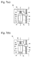
- the ceramic honeycomb body 10 having large numbers of longitudinal cells partitioned by cell walls is rotatably held by fixing jigs 21, 22 on the main axis of the lathe 30.
- the lathe 30 comprises a first fixing jig 21 on the main axis Z, and a second fixing jig 22 attached to a tail stock 35 to substantially oppose the first fixing jig 21.
- Opposing end portions of the first fixing jig 21 and the second fixing jig 22 have abutting portions 210, 220 having smaller outer shapes than those of longitudinal end surfaces 5a, 5b of the ceramic honeycomb body 10; end surfaces of the abutting portions 210, 220 having substantially flat abutting surfaces 211, 221 perpendicular to the main axis Z.
- the ceramic honeycomb body 10 is held by abutting both end surfaces 5a, 5b of the ceramic honeycomb body 10 to the end surfaces 211, 221 of the abutting portions 210, 220 of the first and second fixing jigs 21, 22, such that the center axis of the ceramic honeycomb body 10 is substantially in alignment with the main axis Z, and moving the second fixing jig 22 attached to the tail stock 35 toward the other fixing jig 21 to press both end surfaces 5a, 5b of the ceramic honeycomb body 10 with the abutting surfaces 211, 221 of the fixing jigs 21, 22.
- the method of holding both end surfaces 5a, 5b of the ceramic honeycomb body 10 by pressing which differs from a conventional method of fixing a ceramic honeycomb body 10 by directly gripping its end portion by a chuck, need not cut off an chucked, unmachined end portion of the ceramic honeycomb body 10 after machining, thereby providing a high yield in the production of the ceramic honeycomb body 10, with less breakage in the held portion of the ceramic honeycomb body 10 by a load during machining.
- the ceramic honeycomb body 10 whose both end surfaces 5a, 5b are held by pressing, are rotated around the main axis Z together with the fixing jigs 21, 22, and a tool 41 fixed to a carrier 42 is fed in parallel with the axis by a screw 43, to remove a peripheral portion 12 from the rotating ceramic honeycomb body 10 by machining.
- the tool 41 can be fed along the entire length of the ceramic honeycomb body 10 from the first end surface 5a to the second end surface 5b to remove all the peripheral surface from the ceramic honeycomb body 10, because the abutting portions 210, 220 of the fixing jigs 21, 22 have smaller outer shapes than those of the end surfaces 5a, 5b of the ceramic honeycomb body 10.
- the ceramic honeycomb body 10 has a highly brittle cell structure constituted by porous cell walls, a peripheral portion of the second end surface 5b may be broken when machining is completed (when the tool 41 reaches the second end surface 5b), in the removal of the peripheral portion 12 by feeding the tool 41 from the first end surface 5a toward the second end surface 5b.
- the machining direction is preferably reversed en route, such that machining proceeds from both of the first and second end surfaces 5a, 5b of the ceramic honeycomb body 10, in the removal of the peripheral portion 12 from the ceramic honeycomb body 10 by machining.
- the second end surface 5a and the first end surface 5b of the ceramic honeycomb body 10 are preferably rotatably held by pressing by the abutting surfaces 211, 221 of the first and second fixing jigs 21, 22, such that the center axis of the ceramic honeycomb body 10 is substantially in alignment with the main axis Z of the lathe 30; the held ceramic honeycomb body 10 being rotated around the main axis Z as a center axis; the tool 41 being fed along the rotating ceramic honeycomb body 10 from the first end surface 5b toward the second end surface 5a, to remove the peripheral portion 12 by machining up to a position of 1 mm or more from the second end surface 5a, with an unmachined peripheral portion 12a left on the side of the second end surface 5a, and the feeding of the tool 41 and the rotation of the ceramic honeycomb body 10 being stopped; the first and second fixing jigs 21, 22 being detached from both end surfaces 5a, 5b of the ceramic honeycomb body 10 to release the ceramic
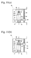
- the tool 41 is fed along the rotating ceramic honeycomb body 10 from the first end surface 5b toward the second end surface 5a, to remove the peripheral portion 12 by machining up to a position of 1 mm or more from the second end surface 5a, and the feeding of the tool 41 being stopped with an unmachined peripheral portion 12a left on the side of the second end surface 5a; the carrier 42 being moved in a direction perpendicular to the main axis Z, so that the tool 41 retreats from the ceramic honeycomb body 10; and the tool 41 being moved to the second end surface 5a of the ceramic honeycomb body 10 as shown in Fig. 10(c) ; and the tool 41 being fed along the rotating ceramic honeycomb body 10 from the second end surface 5a toward the first end surface 5b, to remove the unmachined peripheral portion 12a by machining.
- the outer edges of the first and second end surfaces 5b, 5a of the ceramic honeycomb body 10 may be chamfered to further suppress the breakage of end surface edges when machining is completed.
- a lathe used for the removal of the peripheral portion from the ceramic honeycomb body by machining need not be a so-called general lathe, but may have any structure as long as the ceramic honeycomb body can be attached to a rotating main spindle to remove a peripheral portion therefrom by machining with a tool.
- the main spindle may be directed horizontally, vertically or therebetween.
- a usable tool is a grinding tool, a cutting tool, etc.
- the grinding tool may be a grinder of grinding alumina particles, grinding carbide silicon particles, grinding diamond particles, etc.
- the cutting tool may be a bite of cemented carbide, ceramics, diamond, sintered diamond, sintered CBN, etc.
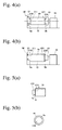
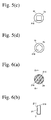
- the abutting portions 210, 220 have smaller outer shapes than those of the end surfaces 5a, 5b of the ceramic honeycomb body 10. This means that for example, when the abutting portion 210 (220) has a substantially circular transverse cross section as shown in Figs. 5(a) and 5(b) , the cross section of the abutting portion 210 (220) has a smaller diameter than that of the end surface 5a (5b) of the ceramic honeycomb body 10. Namely, a ratio (A/B) of the area A of the transverse cross section of the abutting portion 210 (220) to the area B of the end surface 5a (5b) of the ceramic honeycomb body 10 is less than 1.
- a transverse center of the cross section of the abutting portion 210 is preferably on the main axis of the lathe.
- the transverse cross section of the abutting portion 210 preferably has substantially the same outer shape as that of the abutting surface 211, 221.
- the transverse cross section of the abutting portion 210, 220 is not restricted to have a circular shape as shown in Fig. 5(b) , but may have a rectangular shape as shown in Fig. 5(c) , a hexagonal shape as shown in Fig. 5(d) , or other shapes.
- the transverse cross section of the abutting portion 210, 220 has a polygonal shape in place of a circular shape, that the abutting portion 210, 220 has a smaller outer shape than that of the end surface 5a, 5b of the ceramic honeycomb body 10 means that a minimum circle including the polygonal shape has a smaller diameter than that of the end surface 5a, 5b of the ceramic honeycomb body 10.
- a ratio (A/B) of the area A of the minimum circle including the polygonal shape to the area B of the end surface 5a, 5b of the ceramic honeycomb body 10 is less than 1.
- the ratio A/B is preferably 0.3 or more, more preferably 0.5 or more.
- the abutting portions 210, 220 have smaller outer shapes than those of the end surfaces 5a, 5b of the ceramic honeycomb body 10, other portions of the fixing jigs 21, 22 than the abutting portions 210, 220 need not have smaller outer shapes than those of the end surfaces 5a, 5b of the ceramic honeycomb body 10.
- other portions of the fixing jigs 21, 22 than the abutting portions 210, 220 may have larger outer shapes than those of the abutting portions 210, 220.
- other portions of the fixing jigs 21, 22 than the abutting portions 210, 220 may have smaller outer shapes than those of the abutting portions 210, 220.
- the abutting portions 210, 220 may be detachable from the fixing jigs 21, 22.
- the abutting portions 210, 220 having smaller outer shapes than those of the end surfaces 5a, 5b of the ceramic honeycomb body 10, which have substantially flat abutting surfaces 211, 221 brought into contact with the end surfaces 5a, 5b of the ceramic honeycomb body 10, may be detachably fixed to the fixing jigs 21, 22 with bolts, screws, nails, adhesives, etc.
- the abutting portions 210, 220 may be made of different materials from those of the fixing jigs 21, 22, making it possible to effectively prevent breakage in the ceramic honeycomb body 10 pressed by both end surfaces 5a, 5b of the ceramic honeycomb body 10.
- the abutting portions 210, 220 are preferably made of nonmetallic materials such as resins, woods, etc., particularly resins.
- a ratio of the area C of each abutting surface 211, 221 to the transverse cross section area A of each abutting portion 210, 220 is preferably 30-100%.
- the area ratio C/A of 30-100% is achieved by having, for example, a recess 24 in the abutting surface 211 as shown in Figs. 6(a) and 6(b) .
- a hatched portion in Fig. 6(a) is the area C of the abutting surface 211.
- This area ratio C/A is preferably 50-100%, more preferably 70-100%.
- the abutting surfaces 211, 221 brought into contact with the end surfaces 5a, 5b of the ceramic honeycomb body 10 preferably have surface roughness (maximum height Rz) of 10-500 ⁇ m.
- the surface roughness is less than 10 ⁇ m, the end surfaces 5a, 5b of the ceramic honeycomb body 10 is not sufficiently held, so that the ceramic honeycomb body 10 may be displaced by a machining load, breaking its held portions.
- the surface roughness is more than 500 ⁇ m, a load is likely applied to both end surfaces 5a, 5b of the ceramic honeycomb body 10 when pressed, making the breakage of the end surfaces 5a, 5b likely.
- the surface roughness is preferably 50-400 ⁇ m, more preferably, 80-350 ⁇ m.
- a large ceramic honeycomb body 10 of 150 mm or more in outer diameter and 150 mm or more in length is machined by the lathe 30, the ceramic honeycomb body 10 should be held with a larger force to withstand its own weight.
- the end surfaces 5a, 5b may be broken.
- a lathe 50 is provided with a substantially vertical main axis, and the ceramic honeycomb body 10 is disposed substantially vertically, so that a large ceramic honeycomb body 10 can be surely held under relatively low pressure.
- a machining method using such a lathe 50 with a substantially vertical main axis will be explained in detail below.
- the lathe 50 with a substantially vertical main axis Z comprising a first fixing jig 21 disposed on the main axis Z, and a second fixing jig 22 mounted to an upper fixing member 55 and substantially opposing the first fixing jig 21.
- the first and second fixing jigs 21, 22 have abutting end portions 210, 220 opposing each other, the abutting end portions 210, 220 having smaller outer shapes than those of the end surfaces 5a, 5b of the ceramic honeycomb body 10, and the end surfaces 5a, 5b of the abutting portions 210, 220 having substantially flat abutting end surfaces 211, 221 perpendicular to the main axis.
- the ceramic honeycomb body 10 is held by bringing the abutting surfaces 211, 221 of the first and second fixing jigs 21, 22 into contact with both end surfaces 5a, 5b of the ceramic honeycomb body 10, such that the center axis of the ceramic honeycomb body 10 is substantially in alignment with the main axis Z of the lathe 50, and vertically moving the second fixing jig 22 mounted to the upper fixing member 55 to press both end surfaces 5a, 5b of the ceramic honeycomb body 10.
- the ceramic honeycomb body 10 with both end surfaces 5a, 5b pressed for holding is rotated around the main axis Z together with the fixing jigs 21, 22, and a tool 61 fixed to a carrier 62 is fed by a screw 63 in parallel with the main axis Z while biting a peripheral portion 12 of the rotating ceramic honeycomb body 10, so that the peripheral portion 12 is removed by machining.
- a large ceramic honeycomb body 10 of 150 mm or more in outer diameter and 150 mm or more in length can be surely held by relatively low pressure applied to both end surfaces 5a, 5b thereof. Accordingly, even when a large load is applied during machining to remove the peripheral portion 12, the held portions of the ceramic honeycomb body 10 are not broken. Because the ceramic honeycomb body 10 can be surely held by relatively small pressure, the ceramic honeycomb body 10 is unlikely displaced by a machining load, thereby preventing the breakage of the peripheral surface during machining.
- peripheral portion 12 can be removed from the entire length of the ceramic honeycomb body 10 from the first end surface 5a to the second end surface 5b by machining, a step of removing a chucked portion is not needed, resulting in a high yield in the production of the ceramic honeycomb body 10.
- the center axis of the ceramic honeycomb body 10 is substantially aligned with the main axis of the lathe Z for the high-precision machining of the peripheral portion of the ceramic honeycomb body 10.
- the center axis of the ceramic honeycomb body 10 can be easily aligned with the main axis of the lathe Z.
- Each positioning jig 81 (82) comprises a rod member 81c (82c) extending in the X-axis direction, and two-pronged contact members 81a, 81b (82a, 82b) extending from a tip end of the rod member 81c (82c) and expanding with an angle ⁇ from the X-axis.
- the two-pronged contact members 81a, 81b of the positioning jig 81 and the two-pronged contact members 82a, 82b of the positioning jig 82 are opposing, and movably disposed in the X-axis direction so that they can fix the ceramic honeycomb body 10, with the contact members 81a, 81b, 82a, 82b in contact with the peripheral surface of the ceramic honeycomb body 10 at four points.
- positions on the peripheral surface of the ceramic honeycomb body 10, at which the center axis Z H of the ceramic honeycomb body 10 is in alignment with the main axis Z, are calculated from its outer diameter, and the stop positions of the positioning jigs 81, 82 are determined such that the contact members 81a, 81b and the contact members 82a, 82b come into contact with the peripheral surface.
- one positioning jig 81 is first moved in the X-axis direction to the stop position determined in advance, which is near the ceramic honeycomb body 10 as shown in Fig. 8(c) .
- the ceramic honeycomb body 10 may be moved together with the contact members 81a, 81b, depending on its initial position.
- another positioning jig 82 is then moved in the X-axis direction to the stop position determined in advance, such that the ceramic honeycomb body 10 is moved by the contact members 82a, 82b.
- the ceramic honeycomb body 10 moves in both X-axis and Y-axis directions, so that displacement in both X-axis and Y-axis directions is eliminated.
- the ceramic honeycomb body 10 With the positioning jig 82 moved to the stop position determined in advance, the ceramic honeycomb body 10 is fixed by the contact members 81a, 81b and the contact members 82a, 82b at four points, so that the center axis Z H of the ceramic honeycomb body 10 is substantially in alignment with the main axis of the lathe Z.
- the removal of the peripheral portion 12 from the ceramic honeycomb body 10 by machining is preferably conducted by cutting the ceramic honeycomb body 10 rotating at a circumferential speed of 1-10 m/s, at a longitudinal feeding rate of 0.1-1 mm/rev.
- the circumferential speed is less than 1 m/s
- the peripheral portion 12 is not sufficiently removed by machining, leaving unmachined portions.
- it exceeds 10 m/s a large load is applied to the end surfaces 5a, 5b of the ceramic honeycomb body 10 during machining, making it likely to break the held portions of the ceramic honeycomb body 10.
- the feeding rate is less than 0.1 mm/rev, too much time is needed for machining, resulting in low efficiency.
- the 1 mm/rev a large load is applied during machining, making it likely to break the held portions of the ceramic honeycomb body 10.
- the method of the present invention for removing a peripheral portion by machining is applicable to both an unsintered ceramic honeycomb body and a sintered ceramic honeycomb body. Because the sintered ceramic honeycomb body more likely suffers breakage in held portions during machining the peripheral portion with a lathe, because it has lower strength by loosing a binder existing in the unsintered ceramic honeycomb body. Particularly in the case of a high-porosity honeycomb body, its tendency is remarkable. Accordingly, the method of the present invention is effective particularly when used on a sintered ceramic honeycomb body and a high-porosity honeycomb body.
- a peripheral surface of the ceramic honeycomb body with its peripheral portion removed by machining is coated with a coating material, dried, and if necessary, sintered to a ceramic honeycomb structure.
- the coating material may be a paste prepared by blending the ceramic material, colloidal silica or colloidal alumina, a binder, water, and if necessary, a dispersant, etc.
- the ceramic material may be the same as or different from used in the ceramic honeycomb body.
- usable ceramic materials are cordierite, alumina, mullite, silica, aluminum titanate, etc.
- the coating material may contain ceramic fibers and an inorganic or organic binder, in addition to the ceramic material.
- one or the other end portions of flowing paths may be alternately plugged with a plugging material, sintered, and coated with a coating material on the peripheral surface to provide a ceramic honeycomb filter.
- the formation of plugs and sintering may be conducted before removing the peripheral portion by machining.
- the plugging material may be formed by a ceramic material, colloidal silica or colloidal alumina, a binder, water, and if necessary, a dispersant, etc.
- the ceramic material may be cordierite, alumina, mullite, silica, aluminum titanate, etc.
- the ceramic material may be the same as or different from that of the ceramic honeycomb body.
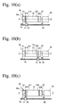
- end of outermost flowing paths 4a and flowing paths 4b inside the outermost flowing paths 4a in predetermined numbers are open on the peripheral surface 11a as shown in Fig. 9(a) .
- Such peripheral surface 11a may be coated with a coating material to form a peripheral wall 11 as shown in Fig. 9(b) .
- the ends of the outermost flowing paths 4a and the flowing paths 4b inside the outermost flowing paths 4a in predetermined numbers are closed by the peripheral wall 11, exhibiting a heat insulation effect. This shortens temperature elevation time from the start of operation, thereby activating a catalyst, if any, in a shorter period of time.
- Kaolin powder, talc powder, silica powder and alumina powder were mixed to form a cordierite-forming material powder comprising 50% by mass of SiO 2 , 36% by mass of Al 2 O 3 and 14% by mass of MgO, and this material powder was sufficiently dry-mixed with 8% by mass in total of methylcellulose and hydroxypropyl methylcellulose as a binder, a lubricant, and 7.0% by mass of foamed resin (average particle size: 40 ⁇ m) as a pore-forming material, and then fully blended with water to prepare a plasticized, moldable ceramic material.
- a cordierite-forming material powder comprising 50% by mass of SiO 2 , 36% by mass of Al 2 O 3 and 14% by mass of MgO, and this material powder was sufficiently dry-mixed with 8% by mass in total of methylcellulose and hydroxypropyl methylcellulose as a binder, a lubricant, and 7.0% by mass of foamed resin (average particle size: 40
- This moldable ceramic material was extruded, cut to a predetermined length to produce a honeycomb-structured green body having an outer diameter of 125 mm and a length of 150 mm, and dried for 20 minutes in a microwave-drying furnace to obtain a dried ceramic honeycomb body.
- a peripheral portion 12 of the ceramic honeycomb body 10 was removed by machining by a method below.
- the lathe A comprised a first fixing jig 21 on its main axis Z, and a second fixing jig 22 mounted to a tail stock 35 such that it opposed the first fixing jig 21, opposing end portions of the first and second fixing jigs 21, 22 had abutting portions 210, 220 having substantially flat abutting surfaces 211, 221 perpendicular to the main axis Z.
- Each abutting portion 210, 220 which was made of steel, had a circular cross section of 90 mm in diameter [see Figs. 5(a) and 5(b) ], a percentage of the abutting surface 211, 221 to the abutting portion 210, 220 being 100%, and the abutting surface 211, 221 having surface roughness (maximum height Rz) of 200 ⁇ m.
- the second end surface 5a and first end surface 5b of the ceramic honeycomb body 10 were in contact with the abutting surfaces 211, 221 of the abutting portions 210, 220, such that the center axis of the ceramic honeycomb body 10 were substantially in alignment with the main axis Z, and pressed by the second fixing jig 22 mounted to the tail stock 35 to pressure-hold both end surfaces 5a, 5b of the ceramic honeycomb body 10.
- This held ceramic honeycomb body 10 was rotated around the main axis Z at a circumferential speed of 5 m/s, so that a peripheral portion 12 was removed from the entire length of the ceramic honeycomb body 10 from the first end surface 5b to the second end surface 5a, by machining with a cemented carbide bite (tool 41) fixed to a carrier 42, at a cutting depth of 2 mm and a feeding rate of 0.5 mm/rev.
- a cemented carbide bite tool 41
- the ceramic honeycomb body 10 was taken out of the fixing jigs 21, 22, to evaluate the breakage of the held portions and peripheral surface of the ceramic honeycomb body 10, and a yield.
- the ceramic honeycomb body 10 after evaluation was sintered by an 8-day schedule having the highest temperature of 1410°C in a sintering furnace, and a peripheral surface of the sintered ceramic honeycomb body 10 was coated with a coating material comprising cordierite powder, a binder and water to a thickness of 1 mm, and dried to provide a ceramic honeycomb structure.
- the breakage of the holding portions of the ceramic honeycomb body 10 was evaluated by the following standard, by observing the end surfaces 5a, 5b of the machined ceramic honeycomb body 10 by the naked eye. The results are shown in Table 1. Excellent No breakage occurred. Good Breakage of less than 0.5 mm occurred. Fair Breakage of 0.5 mm or more and less than 1 mm occurred. Poor Breakage of 1 mm or more occurred.
- the breakage of the peripheral surface of the ceramic honeycomb body 10 was evaluated by the following standard, by observing the peripheral surface of the machined ceramic honeycomb body 10 by the naked eye. The results are shown in Table 1. Excellent No breakage occurred. Good Breakage of less than 0.5 mm occurred. Fair Breakage of 0.5 mm or more and less than 1 mm occurred. Poor Breakage of 1 mm or more occurred.
- the yield was evaluated by a mass ratio of the machined ceramic honeycomb body 10 to the ceramic honeycomb body 10 before peripheral machining, by the following standard. The results are shown in Table 1. Excellent Yield was 95% or more. Good Yield was 90% or more and less than 95%. Poor Yield was less than 90%.
- a dried ceramic honeycomb body 10 was produced in the same manner as in Example 1, and a peripheral portion 12 was removed from the dried ceramic honeycomb body 10 by machining with a lathe 30 (lathe B) shown in Figs. 3(a) and 3(b) in the same manner as in Example 1, except for changing the abutting portions 210, 220 and the machining conditions (circumferential speed and feed rate) as shown in Table 1.
- the lathe B used herein was the same as the lathe A used in Example 1, except that abutting portions 210, 220 as separate members were threadably attached to the fixing jigs 21, 22, so that abutting portions 210, 220 were exchangeable.
- the same evaluation as in Example 1 was conducted, and sintering and the application of a coating material to the peripheral surface were conducted in the same manner as in Example 1 to produce a ceramic honeycomb structure.
- a dried ceramic honeycomb body 10 was produced in the same manner as in Example 1, and this dried body was sintered by an 8-day schedule having the highest temperature of 1410°C in a sintering furnace, to obtain a sintered ceramic honeycomb body 10.
- a peripheral portion 12 of this sintered ceramic honeycomb body 10 was removed by machining in the same manner as in Examples 2-7, except for changing the abutting portions 210, 220 and the machining conditions (circumferential speed and feed rate) as shown in Table 1.
- the abutting member used in Example 9 had a rectangular cross section [see Fig. 5(c) ], and the abutting member used in Example 10 had a hexagonal cross section [see Fig. 5(d) ].
- the same evaluation as in Example 1 was conducted, and sintering and the application of a coating material to the peripheral surface were conducted in the same manner as in Example 1, to produce a ceramic honeycomb structure.
- a sintered ceramic honeycomb body 10 was produced in the same manner as in Example 10, and as described in detail below, a peripheral portion 12 was removed from the sintered ceramic honeycomb body 10 by machining in the same manner as in Example 10, except for reversing the machining direction en route, such that machining proceeded from both of the first and second end surfaces 5a, 5b of the ceramic honeycomb body 10.
- the ceramic honeycomb body 10 was first held in the same manner as in Example 1, and a cemented carbide bite (tool 41) was fed from the first end surface 5b toward the second end surface 5a as shown in Fig. 10(a) , to remove a peripheral portion 12 under the machining conditions (circumferential speed and feed rate) shown in Table 1. After the peripheral portion 12 was removed by machining up to a position of 5 mm from the second end surface 5a, the feeding of the cemented carbide bite (tool 41) was stopped with an unmachined peripheral end portion 12a of 5 mm left on the side of the second end surface 5a.
- the first and second fixing jigs 21, 22 were released from both end surfaces 5a, 5b of the ceramic honeycomb body 10, to detach the ceramic honeycomb body 10 from the lathe 30.
- the first end surface 5b and the second end surface 5a were then reversed as shown in Fig.
- Example 2 After the completion of machining, the same evaluation as in Example 1 was conducted, and sintering and the application of a coating material to the peripheral surface were conducted in the same manner as in Example 1, to produce a ceramic honeycomb structure.
- a sintered ceramic honeycomb body 10 was produced in the same manner as in Example 10, and a peripheral portion 12 was removed from the sintered ceramic honeycomb body 10 by machining in the same manner as in Example 11, except for reversing the feeding direction of a cemented carbide bite (tool 41) en route as described in detail below, instead of reversing the direction of the ceramic honeycomb body 10 en route, such that machining proceeded from both of the first and second end surfaces 5a, 5b of the ceramic honeycomb body 10.
- a cemented carbide bite (tool 41) en route as described in detail below
- a cemented carbide bite (tool 41) was fed from the first end surface 5b toward the second end surface 5a as shown in Fig. 10(a) , under the machining conditions (circumferential speed and feed rate) shown in Table 1, to remove a peripheral portion 12 by machining. After the peripheral portion 12 was removed by machining up to a position of 5 mm from the second end surface 5a, the feeding of the cemented carbide bite (tool 41) was stopped, with an unmachined peripheral end portion 12a of 5 mm left on the side of the second end surface 5a.
- the tool 41 was then retreated from the ceramic honeycomb body 10 by moving the carrier 42 in a perpendicular direction to the main axis Z, and the tool 41 was moved to the second end surface 5a of the ceramic honeycomb body 10 as shown in Fig. 10(c) .
- the cemented carbide bite (tool 41) was then fed along the rotating ceramic honeycomb body 10 from the second end surface 5a toward the first end surface 5b, to remove the unmachined peripheral portion 12a by machining under the same conditions as described above.
- Example 2 After the completion of machining, the same evaluation as in Example 1 was conducted, and sintering and the application of a coating material to the peripheral surface were conducted in the same manner as in Example 1, to produce a ceramic honeycomb structure.
- a dried ceramic honeycomb body 10 was obtained in the same manner as in Example 1, except for changing the size of an extrudate having a honeycomb structure to an outer diameter of 270 mm and a length of 300 mm.
- a peripheral portion 12 was removed from the ceramic honeycomb body 10 by machining by a method below using a lathe 50 (lathe C) having a vertical main axis as shown in Fig. 7(a) .
- a lathe 50 (lathe C) having a substantially vertical main axis Z comprises a first fixing jig 21 on the main axis Z, and a second fixing jig 22 mounted to an upper fixing member 55 and substantially opposing the first fixing jig 21.
- the first and second fixing jigs 21, 22 comprise abutting end portions 210, 220 opposing each other, which have smaller outer shapes than those of the end surfaces 5a, 5b of the ceramic honeycomb body 10, the end surfaces 5a, 5b of the abutting portions 210, 220 have substantially flat abutting surfaces perpendicular to the main axis 211, 221.
- Each abutting portion 210, 220 has a circular transverse cross section of 200 mm in diameter, and is made of steel. A ratio of the abutting surface 211, 221 to the abutting portion 210, 220 was 100%, and the abutting surface 211, 221 had surface roughness (maximum height Rz) of 200 ⁇ m.
- the abutting surfaces 211, 221 of the abutting portions 210, 220 were brought into contact with the second and first end surfaces 5a, 5b of the ceramic honeycomb body 10, such that the center axis of the ceramic honeycomb body 10 was substantially in alignment with the main axis Z of the lathe 50 (lathe C), and the second fixing jig 22 mounted to the upper fixing member 55 was vertically moved to press both end surfaces 5a, 5b of the ceramic honeycomb body 10.
- This ceramic honeycomb body 10 thus held was rotated around the main axis Z at a circumferential speed of 5 m/s, and the peripheral portion 12 was removed from the entire length of the ceramic honeycomb body 10 from the first end surface 5b to the second end surface 5a by machining with a cemented carbide bite (tool 61) fixed to a carrier 62 at a cutting depth of 2 mm and a feeding rate of 0.5 mm/rev.
- a cemented carbide bite (tool 61) fixed to a carrier 62 at a cutting depth of 2 mm and a feeding rate of 0.5 mm/rev.
- the positioning of the dried ceramic honeycomb body 10 on the lathe was conducted as described below, using positioning jigs 81, 82 shown in Fig. 8(a) .
- Positions on the peripheral surface of the ceramic honeycomb body 10, at which its center axis Z H was in alignment with the main axis Z, were first calculated from the outer diameter (270 mm) of the ceramic honeycomb body 10, and the stop positions of the positioning jigs 81, 82 were determined such that the contact members 81a, 81b and the contact members 82a, 82b were located at the calculated positions on the peripheral surface.
- the ceramic honeycomb body 10 was placed in a state where the center axis ZH was not in alignment with the main axis of the lathe Z as shown in Figs. 8(a) and 8(b) , and one positioning jig 81 was moved in the X-axis direction to a stop position determined in advance near the ceramic honeycomb body 10, as shown in Fig. 8(c) .
- FIG. 8(d) another positioning jig 82 was then moved in the X-axis direction, so that the ceramic honeycomb body 10 was moved by the contact members 82a, 82b.
- the ceramic honeycomb body 10 moves in both X-axis and directions, so that displacement in the X-axis and directions was eliminated.
- the ceramic honeycomb body 10 was fixed by the contact members 81a, 81b and contact members 82a, 82b at four points, such that the center axis Z H of the ceramic honeycomb body 10 was substantially in alignment with the main axis of the lathe Z.
- Example 2 After the completion of machining, the same evaluation as in Example 1 was conducted, and sintering and the application of a coating material to the peripheral surface were conducted in the same manner as in Example 1, to produce a ceramic honeycomb structure.
- a peripheral portion 12 was removed by machining from a dried ceramic honeycomb body 10 produced in the same manner as in Example 13, except for changing the abutting portions 210, 220 and the machining conditions (circumferential speed and feed rate) as shown in Table 1.
- a lathe D used here was the same as the lathe C used in Example 13, except for comprising abutting portions 210, 220 as separate members, which were detachably attached to the fixing jigs 21, 22 by bolts.
- the same evaluation as in Example 1 was conducted, and sintering and the application of a coating material to the peripheral surface were conducted in the same manner as in Example 1, to produce a ceramic honeycomb structure.
- a dried ceramic honeycomb body 10 was produced in the same manner as in Example 13, and this dried body was sintered by 8-day schedule having the highest temperature of 1410°C in a sintering furnace, to obtain a sintered ceramic honeycomb body 10.
- a peripheral portion 12 of this sintered ceramic honeycomb body 10 was removed by machining in the same manner as in Examples 14-19, except for changing the abutting portions 210, 220 and the machining conditions (circumferential speed and feed rate) as shown in Table 1.
- the abutting member used in Example 21 had a rectangular cross section [see Fig. 5(c) ], and the abutting member used in Example 22 had a hexagonal cross section [see Fig. 5(d) ].
- the same evaluation as in Example 1 was conducted, and sintering and the application of a coating material to the peripheral surface were conducted in the same manner as in Example 1, to produce a ceramic honeycomb structure.
- a sintered ceramic honeycomb body 10 was produced in the same manner as in Example 22, and a peripheral portion 12 was removed from the ceramic honeycomb body 10 by machining in the same manner as in Example 22, except for reversing the machining direction en route as described in detail below, such that machining proceeded from both of the first and second end surfaces 5a, 5b of the ceramic honeycomb body 10.
- a cemented carbide bite (tool 61) was fed from the first end surface 5b toward the second end surface 5a as shown in Fig. 11(a) , to remove a peripheral portion 12 by machining under the machining conditions (circumferential speed and feed rate) shown in Table 1. After the peripheral portion 12 was removed by machining up to a position of 5 mm from the second end surface 5a, the feeding of the cemented carbide bite (tool 61) and the rotation of the ceramic honeycomb body 10 were stopped, with an unmachined end peripheral portion 12a left on the side of the second end surface 5a.
- the first and second fixing jigs 21, 22 were released from both end surfaces 5a, 5b of the ceramic honeycomb body 10, to take the ceramic honeycomb body 10 out of the lathe 30.
- the first end surface 5b and the second end surface 5a were then reversed, namely, the first end surface 5b and second end surface 5a of the ceramic honeycomb body 10 were brought into contact with the abutting surface 211 of the first fixing jig 21 and the abutting surface 221 of the second fixing jig 22, such that the center axis of the ceramic honeycomb body 10 was substantially in alignment with the main axis Z of the lathe 30.
- the ceramic honeycomb body 10 was rotated around the main axis Z, and the cemented carbide bite (tool 61) was fed from the second end surface 5a toward the first end surface 5b, to remove the unmachined peripheral portion 12a by machining under the same conditions as described above.
- Example 2 After the completion of machining, the same evaluation as in Example 1 was conducted, and sintering and the application of a coating material to the peripheral surface were conducted in the same manner as in Example 1, to produce a ceramic honeycomb structure.
- a sintered ceramic honeycomb body 10 was produced in the same manner as in Example 22, and a peripheral portion 12 was removed from the sintered ceramic honeycomb body 10 by machining in the same manner as in Example 23, except that the feeding direction of the cemented carbide bite (tool 41) was reversed en route as described in detail below, instead of reversing the direction of the ceramic honeycomb body 10 en route, such that machining proceeded from both of the first and second end surfaces 5a, 5b of the ceramic honeycomb body 10.
- a cemented carbide bite (tool 61) was fed from the first end surface 5b toward the second end surface 5a as shown in Fig. 11(a) , to remove a peripheral portion 12 by machining under the machining conditions (circumferential speed and feed rate) shown in Table 1.
- the feeding of the cemented carbide bite (tool 61) was stopped with an unmachined peripheral end portion 12a of 5 mm left on the side of the second end surface 5a.
- the tool 61 was then retreated from the ceramic honeycomb body 10 by moving the carrier 62 in a perpendicular direction to the main axis Z.
- the cemented carbide bite (tool 41) was fed from the second end surface 5a toward the first end surface 5b as shown in Fig. 11(c) , to remove an unmachined peripheral portion 12a from the rotating ceramic honeycomb body 10 by machining under the same conditions as described above.
- Example 2 After the completion of machining, the same evaluation as in Example 1 was conducted, and sintering and the application of a coating material to the peripheral surface were conducted in the same manner as in Example 1, to produce a ceramic honeycomb structure.
- a dried ceramic honeycomb body 10 was produced in the same manner as in Example 1 except for changing its length to 170 mm, resulting in the dried ceramic honeycomb body 10 having an outer diameter of 125 mm and a length of 170 mm.
- a peripheral portion 12 was removed from the dried ceramic honeycomb body 10 by machining.
- One end portion of the ceramic honeycomb body 10 was held by a scroll chuck 91 on the main axis Z of the lathe E, to fix the ceramic honeycomb body 10 to the lathe E.
- the ceramic honeycomb body 10 was rotated around the main axis Z at a circumferential speed of 5 m/s, and a cemented carbide bite (not shown) fixed to a carrier was fed to remove the peripheral portion 12 from the ceramic honeycomb body 10 by machining at a cutting depth of 2 mm and a feeding rate of 0.5 mm/rev.
- a dried ceramic honeycomb body 10 produced in the same manner as in Comparative Example 1 was sintered by an 8-day schedule having the highest temperature of 1410°C in a sintering furnace, to obtain a sintered ceramic honeycomb body 10 having an outer diameter of 125 mm and a length of 170 mm.
- a dried ceramic honeycomb body 10 produced in the same manner as in Example 1 was sintered by an 8-day schedule having the highest temperature of 1410°C in a sintering furnace, to obtain a sintered ceramic honeycomb body 10.
- a peripheral portion 12 was removed from the ceramic honeycomb body 10 by machining in the same manner as in Example 1, except for changing the abutting portions 210, 220 to circular members having a diameter of 150 mm. After the completion of machining, the same evaluation as in Example 1 was conducted.
- the abutting surface of the abutting member had a larger outer shape than that of the ceramic honeycomb body in Comparative Example 3, a peripheral portion near an end portion of the ceramic honeycomb body could not be removed by machining, so that an unmachined portion had to be cut off, resulting in a low yield.
- the method of the present invention can provide a high-quality ceramic honeycomb body with a high yield, with a suppressed production cost.
Landscapes
- Chemical & Material Sciences (AREA)
- Engineering & Computer Science (AREA)
- Ceramic Engineering (AREA)
- Structural Engineering (AREA)
- Organic Chemistry (AREA)
- Materials Engineering (AREA)
- Mechanical Engineering (AREA)
- Inorganic Chemistry (AREA)
- Mining & Mineral Resources (AREA)
- Devices For Post-Treatments, Processing, Supply, Discharge, And Other Processes (AREA)
- Filtering Materials (AREA)
- Press-Shaping Or Shaping Using Conveyers (AREA)
- Processing Of Stones Or Stones Resemblance Materials (AREA)
- Manufacturing & Machinery (AREA)
Applications Claiming Priority (2)
| Application Number | Priority Date | Filing Date | Title |
|---|---|---|---|
| JP2012083561 | 2012-04-02 | ||
| PCT/JP2013/058752 WO2013150919A1 (fr) | 2012-04-02 | 2013-03-26 | Procédé de fabrication d'un corps en nid d'abeille en céramique |
Publications (3)
| Publication Number | Publication Date |
|---|---|
| EP2835239A1 true EP2835239A1 (fr) | 2015-02-11 |
| EP2835239A4 EP2835239A4 (fr) | 2015-11-11 |
| EP2835239B1 EP2835239B1 (fr) | 2018-12-12 |
Family
ID=49300412
Family Applications (1)
| Application Number | Title | Priority Date | Filing Date |
|---|---|---|---|
| EP13772540.4A Active EP2835239B1 (fr) | 2012-04-02 | 2013-03-26 | Procédé de fabrication d'un corps en nid d'abeille en céramique |
Country Status (6)
| Country | Link |
|---|---|
| US (1) | US9962770B2 (fr) |
| EP (1) | EP2835239B1 (fr) |
| JP (1) | JP6011613B2 (fr) |
| KR (1) | KR102013760B1 (fr) |
| CN (1) | CN104220222B (fr) |
| WO (1) | WO2013150919A1 (fr) |
Families Citing this family (11)
| Publication number | Priority date | Publication date | Assignee | Title |
|---|---|---|---|---|
| JP5629729B2 (ja) * | 2012-06-27 | 2014-11-26 | 日本碍子株式会社 | セラミックハニカム構造体の製造方法 |
| JP6407773B2 (ja) * | 2015-03-13 | 2018-10-17 | 日本碍子株式会社 | ハニカム構造体の製造方法、及び研削用砥石 |
| JP2017064828A (ja) * | 2015-09-29 | 2017-04-06 | Kyb株式会社 | ワーク端面把持装置 |
| CN107999785A (zh) * | 2015-11-13 | 2018-05-08 | 芜湖楚江合金铜材有限公司 | 金属杆件表皮清理机构 |
| CN106914760B (zh) * | 2015-12-28 | 2019-03-12 | 宁波创润新材料有限公司 | 机械加工的固定装置、车床及加工方法 |
| JP6635847B2 (ja) | 2016-03-31 | 2020-01-29 | 日本碍子株式会社 | ハニカム成形体の切断方法、及びハニカム構造体の製造方法 |
| WO2018030120A1 (fr) | 2016-08-10 | 2018-02-15 | 日本碍子株式会社 | Procédé de fabrication de pièces meulées, et meule boisseau |
| JP7082583B2 (ja) * | 2019-01-24 | 2022-06-08 | 日本碍子株式会社 | セラミックスハニカム構造体の加工方法及び加工装置 |
| KR102208228B1 (ko) * | 2019-05-27 | 2021-01-26 | 최지환 | 엔진밸브용 연마 및 선삭장치 |
| US20220008852A1 (en) * | 2020-07-09 | 2022-01-13 | Regents Of The University Of Minnesota | Methods in forming temperature resistant inorganic nano-scale membrane layer for improved high temperature filtration |
| JP7572270B2 (ja) * | 2021-03-09 | 2024-10-23 | 日本碍子株式会社 | ハニカム構造体の製造方法及び装置 |
Family Cites Families (23)
| Publication number | Priority date | Publication date | Assignee | Title |
|---|---|---|---|---|
| JPS60186160U (ja) | 1984-05-17 | 1985-12-10 | 住友電気工業株式会社 | 外径研削用治具 |
| JPH06263564A (ja) * | 1993-03-10 | 1994-09-20 | Kubota Corp | セラミックスパイプの硬化剤層形成装置 |
| US5487694A (en) * | 1993-11-12 | 1996-01-30 | Corning Incorporated | Method for shaping honeycomb substrates |
| JPH0966401A (ja) * | 1995-06-21 | 1997-03-11 | Canon Inc | 円筒部材およびその製造方法ならびに製造装置 |
| JP3125980B2 (ja) * | 1996-10-02 | 2001-01-22 | 日本碍子株式会社 | セラミック製細長円筒部品のチャック・加工方法及び装置 |
| US6758640B2 (en) * | 2000-10-11 | 2004-07-06 | Fuji Seiko Limited | Method and apparatus for controlling movement of cutting blade and workpiece |
| US20020105139A1 (en) * | 2000-11-28 | 2002-08-08 | Ficinski Marek B. | Intellectual matching toy and method of manufacturing |
| JP4069613B2 (ja) * | 2001-11-09 | 2008-04-02 | 株式会社デンソー | セラミックハニカム構造体の製造方法及び乾燥装置 |
| JP2003291054A (ja) | 2002-03-29 | 2003-10-14 | Ngk Insulators Ltd | ハニカム構造体の製造方法 |
| JP4474633B2 (ja) | 2002-06-17 | 2010-06-09 | 日立金属株式会社 | セラミックハニカム構造体の製造方法 |
| US7727613B2 (en) * | 2002-06-17 | 2010-06-01 | Hitachi Metals, Ltd. | Ceramic honeycomb structure, process for producing the same and coat material for use in the production |
| CN100344587C (zh) | 2003-03-05 | 2007-10-24 | 日本碍子株式会社 | 蜂窝状结构体及其制造方法 |
| US7452263B2 (en) * | 2003-11-19 | 2008-11-18 | Ngk Insulators, Ltd. | Grinding method |
| US20060228519A1 (en) * | 2004-03-05 | 2006-10-12 | Ngk Insulators, Ltd. | Honeycomb structure and method of producing the same |
| JP4870558B2 (ja) * | 2004-12-27 | 2012-02-08 | イビデン株式会社 | ハニカム構造体及びシール材層 |
| JP5313670B2 (ja) * | 2006-06-23 | 2013-10-09 | 日本碍子株式会社 | ハニカム構造体及びその製造方法 |
| WO2008004492A1 (fr) | 2006-07-03 | 2008-01-10 | Ngk Insulators, Ltd. | Structure en nid d'abeilles et procédé pour sa fabrication |
| EP2067589B1 (fr) * | 2006-09-28 | 2012-04-11 | Hitachi Metals, Ltd. | Procédé et appareil pour fabriquer une structure en nid d'abeilles céramique |
| WO2008099454A1 (fr) * | 2007-02-09 | 2008-08-21 | Ibiden Co., Ltd. | Structure en nid d'abeilles et appareil de traitement de gaz d'échappement |
| JP5375600B2 (ja) | 2007-03-26 | 2013-12-25 | 日立金属株式会社 | セラミックハニカム構造体の製造方法 |
| US9089992B2 (en) * | 2007-04-30 | 2015-07-28 | Corning Incorporated | Methods and apparatus for making honeycomb structures with chamfered after-applied akin and honeycomb structures produced thereby |
| US7976769B2 (en) * | 2007-11-30 | 2011-07-12 | Corning Incorporated | Method of manufacturing a ceramic honeycomb structure |
| CN102484188B (zh) * | 2009-07-31 | 2015-02-18 | 电气化学工业株式会社 | Led搭载用晶片及其制造方法、以及使用该晶片的led搭载结构体 |
-
2013
- 2013-03-26 WO PCT/JP2013/058752 patent/WO2013150919A1/fr not_active Ceased
- 2013-03-26 JP JP2014509112A patent/JP6011613B2/ja active Active
- 2013-03-26 US US14/389,924 patent/US9962770B2/en active Active
- 2013-03-26 EP EP13772540.4A patent/EP2835239B1/fr active Active
- 2013-03-26 CN CN201380018433.3A patent/CN104220222B/zh active Active
- 2013-03-26 KR KR1020147028042A patent/KR102013760B1/ko active Active
Also Published As
| Publication number | Publication date |
|---|---|
| JPWO2013150919A1 (ja) | 2015-12-17 |
| US9962770B2 (en) | 2018-05-08 |
| CN104220222A (zh) | 2014-12-17 |
| JP6011613B2 (ja) | 2016-10-19 |
| CN104220222B (zh) | 2016-06-08 |
| KR102013760B1 (ko) | 2019-08-23 |
| WO2013150919A1 (fr) | 2013-10-10 |
| US20150052757A1 (en) | 2015-02-26 |
| KR20140143387A (ko) | 2014-12-16 |
| EP2835239B1 (fr) | 2018-12-12 |
| EP2835239A4 (fr) | 2015-11-11 |
Similar Documents
| Publication | Publication Date | Title |
|---|---|---|
| US9962770B2 (en) | Method for producing ceramic honeycomb body | |
| EP1483421B1 (fr) | Filtre a base d alumine liee par reaction et support membran aire | |
| EP1808423B1 (fr) | Plaque de support pour utilisation dans le chauffage et procédé de chauffage des articles en nid d'abeilles utilisant laditte plaque | |
| EP2853708B1 (fr) | Structure en nid d'abeille | |
| EP2186562A1 (fr) | Structure en nid d'abeille en céramique | |
| EP2098497B1 (fr) | Structure alvéolaire céramique et son procédé de fabrication | |
| EP2153958B1 (fr) | Matrice pour le moulage de segments en nid d'abeille et procédé de production de structures en nid d'abeille | |
| EP2082835B1 (fr) | Procédé de production de corps à structure en nids d'abeille perforé | |
| JP2010115896A (ja) | ハニカム構造体の製造方法 | |
| JP4474633B2 (ja) | セラミックハニカム構造体の製造方法 | |
| EP2105181B1 (fr) | Corps structuré en nid d'abeille | |
| US20160229083A1 (en) | Method of producing die for extrusion molding and method of producing honeycomb structured body | |
| JP4632125B2 (ja) | セラミックハニカム構造体の製造方法 | |
| JP5390171B2 (ja) | ハニカム構造体の製造方法 | |
| JP2007144922A (ja) | セラミックハニカム構造体の製造方法 | |
| JPH1134026A (ja) | ハニカム構造体押出用ダイスおよびその製造方法 | |
| JP6196234B2 (ja) | セラミック体セグメントを作製するための改良された方法および装置 | |
| JP2015501744A5 (fr) | ||
| EP2832513A1 (fr) | Procédé de fabrication d'une structure en nid d'abeilles, et filière d'extrusion | |
| US20150017343A1 (en) | Die for extrusion molding, method of producing die for extrusion molding, extruder, and method of producing honeycomb structured body | |
| EP3192630B1 (fr) | Filière d'extrusion | |
| CN100515562C (zh) | 制造小室结构体的方法 |
Legal Events
| Date | Code | Title | Description |
|---|---|---|---|
| PUAI | Public reference made under article 153(3) epc to a published international application that has entered the european phase |
Free format text: ORIGINAL CODE: 0009012 |
|
| 17P | Request for examination filed |
Effective date: 20141024 |
|
| AK | Designated contracting states |
Kind code of ref document: A1 Designated state(s): AL AT BE BG CH CY CZ DE DK EE ES FI FR GB GR HR HU IE IS IT LI LT LU LV MC MK MT NL NO PL PT RO RS SE SI SK SM TR |
|
| AX | Request for extension of the european patent |
Extension state: BA ME |
|
| DAX | Request for extension of the european patent (deleted) | ||
| RA4 | Supplementary search report drawn up and despatched (corrected) |
Effective date: 20151014 |
|
| RIC1 | Information provided on ipc code assigned before grant |
Ipc: B23B 33/00 20060101ALI20151008BHEP Ipc: B28B 11/12 20060101AFI20151008BHEP Ipc: B23B 5/12 20060101ALI20151008BHEP Ipc: C04B 41/91 20060101ALI20151008BHEP Ipc: B23B 5/34 20060101ALI20151008BHEP Ipc: C04B 41/85 20060101ALI20151008BHEP Ipc: B28B 11/04 20060101ALI20151008BHEP Ipc: B23B 23/00 20060101ALI20151008BHEP |
|
| STAA | Information on the status of an ep patent application or granted ep patent |
Free format text: STATUS: EXAMINATION IS IN PROGRESS |
|
| 17Q | First examination report despatched |
Effective date: 20170502 |
|
| GRAP | Despatch of communication of intention to grant a patent |
Free format text: ORIGINAL CODE: EPIDOSNIGR1 |
|
| STAA | Information on the status of an ep patent application or granted ep patent |
Free format text: STATUS: GRANT OF PATENT IS INTENDED |
|
| INTG | Intention to grant announced |
Effective date: 20180628 |
|
| GRAS | Grant fee paid |
Free format text: ORIGINAL CODE: EPIDOSNIGR3 |
|
| GRAA | (expected) grant |
Free format text: ORIGINAL CODE: 0009210 |
|
| STAA | Information on the status of an ep patent application or granted ep patent |
Free format text: STATUS: THE PATENT HAS BEEN GRANTED |
|
| AK | Designated contracting states |
Kind code of ref document: B1 Designated state(s): AL AT BE BG CH CY CZ DE DK EE ES FI FR GB GR HR HU IE IS IT LI LT LU LV MC MK MT NL NO PL PT RO RS SE SI SK SM TR |
|
| REG | Reference to a national code |
Ref country code: GB Ref legal event code: FG4D |
|
| REG | Reference to a national code |
Ref country code: CH Ref legal event code: EP |
|
| REG | Reference to a national code |
Ref country code: AT Ref legal event code: REF Ref document number: 1075342 Country of ref document: AT Kind code of ref document: T Effective date: 20181215 |
|
| REG | Reference to a national code |
Ref country code: DE Ref legal event code: R096 Ref document number: 602013048137 Country of ref document: DE |
|
| REG | Reference to a national code |
Ref country code: IE Ref legal event code: FG4D |
|
| REG | Reference to a national code |
Ref country code: NL Ref legal event code: MP Effective date: 20181212 |
|
| REG | Reference to a national code |
Ref country code: LT Ref legal event code: MG4D |
|
| PG25 | Lapsed in a contracting state [announced via postgrant information from national office to epo] |
Ref country code: BG Free format text: LAPSE BECAUSE OF FAILURE TO SUBMIT A TRANSLATION OF THE DESCRIPTION OR TO PAY THE FEE WITHIN THE PRESCRIBED TIME-LIMIT Effective date: 20190312 Ref country code: FI Free format text: LAPSE BECAUSE OF FAILURE TO SUBMIT A TRANSLATION OF THE DESCRIPTION OR TO PAY THE FEE WITHIN THE PRESCRIBED TIME-LIMIT Effective date: 20181212 Ref country code: LV Free format text: LAPSE BECAUSE OF FAILURE TO SUBMIT A TRANSLATION OF THE DESCRIPTION OR TO PAY THE FEE WITHIN THE PRESCRIBED TIME-LIMIT Effective date: 20181212 Ref country code: HR Free format text: LAPSE BECAUSE OF FAILURE TO SUBMIT A TRANSLATION OF THE DESCRIPTION OR TO PAY THE FEE WITHIN THE PRESCRIBED TIME-LIMIT Effective date: 20181212 Ref country code: LT Free format text: LAPSE BECAUSE OF FAILURE TO SUBMIT A TRANSLATION OF THE DESCRIPTION OR TO PAY THE FEE WITHIN THE PRESCRIBED TIME-LIMIT Effective date: 20181212 Ref country code: ES Free format text: LAPSE BECAUSE OF FAILURE TO SUBMIT A TRANSLATION OF THE DESCRIPTION OR TO PAY THE FEE WITHIN THE PRESCRIBED TIME-LIMIT Effective date: 20181212 Ref country code: NO Free format text: LAPSE BECAUSE OF FAILURE TO SUBMIT A TRANSLATION OF THE DESCRIPTION OR TO PAY THE FEE WITHIN THE PRESCRIBED TIME-LIMIT Effective date: 20190312 |
|
| REG | Reference to a national code |
Ref country code: AT Ref legal event code: MK05 Ref document number: 1075342 Country of ref document: AT Kind code of ref document: T Effective date: 20181212 |
|
| PG25 | Lapsed in a contracting state [announced via postgrant information from national office to epo] |
Ref country code: AL Free format text: LAPSE BECAUSE OF FAILURE TO SUBMIT A TRANSLATION OF THE DESCRIPTION OR TO PAY THE FEE WITHIN THE PRESCRIBED TIME-LIMIT Effective date: 20181212 Ref country code: GR Free format text: LAPSE BECAUSE OF FAILURE TO SUBMIT A TRANSLATION OF THE DESCRIPTION OR TO PAY THE FEE WITHIN THE PRESCRIBED TIME-LIMIT Effective date: 20190313 Ref country code: RS Free format text: LAPSE BECAUSE OF FAILURE TO SUBMIT A TRANSLATION OF THE DESCRIPTION OR TO PAY THE FEE WITHIN THE PRESCRIBED TIME-LIMIT Effective date: 20181212 Ref country code: SE Free format text: LAPSE BECAUSE OF FAILURE TO SUBMIT A TRANSLATION OF THE DESCRIPTION OR TO PAY THE FEE WITHIN THE PRESCRIBED TIME-LIMIT Effective date: 20181212 |
|
| PG25 | Lapsed in a contracting state [announced via postgrant information from national office to epo] |
Ref country code: NL Free format text: LAPSE BECAUSE OF FAILURE TO SUBMIT A TRANSLATION OF THE DESCRIPTION OR TO PAY THE FEE WITHIN THE PRESCRIBED TIME-LIMIT Effective date: 20181212 |
|
| PG25 | Lapsed in a contracting state [announced via postgrant information from national office to epo] |
Ref country code: CZ Free format text: LAPSE BECAUSE OF FAILURE TO SUBMIT A TRANSLATION OF THE DESCRIPTION OR TO PAY THE FEE WITHIN THE PRESCRIBED TIME-LIMIT Effective date: 20181212 Ref country code: IT Free format text: LAPSE BECAUSE OF FAILURE TO SUBMIT A TRANSLATION OF THE DESCRIPTION OR TO PAY THE FEE WITHIN THE PRESCRIBED TIME-LIMIT Effective date: 20181212 Ref country code: PT Free format text: LAPSE BECAUSE OF FAILURE TO SUBMIT A TRANSLATION OF THE DESCRIPTION OR TO PAY THE FEE WITHIN THE PRESCRIBED TIME-LIMIT Effective date: 20190412 Ref country code: PL Free format text: LAPSE BECAUSE OF FAILURE TO SUBMIT A TRANSLATION OF THE DESCRIPTION OR TO PAY THE FEE WITHIN THE PRESCRIBED TIME-LIMIT Effective date: 20181212 |
|
| PG25 | Lapsed in a contracting state [announced via postgrant information from national office to epo] |
Ref country code: EE Free format text: LAPSE BECAUSE OF FAILURE TO SUBMIT A TRANSLATION OF THE DESCRIPTION OR TO PAY THE FEE WITHIN THE PRESCRIBED TIME-LIMIT Effective date: 20181212 Ref country code: SM Free format text: LAPSE BECAUSE OF FAILURE TO SUBMIT A TRANSLATION OF THE DESCRIPTION OR TO PAY THE FEE WITHIN THE PRESCRIBED TIME-LIMIT Effective date: 20181212 Ref country code: SK Free format text: LAPSE BECAUSE OF FAILURE TO SUBMIT A TRANSLATION OF THE DESCRIPTION OR TO PAY THE FEE WITHIN THE PRESCRIBED TIME-LIMIT Effective date: 20181212 Ref country code: RO Free format text: LAPSE BECAUSE OF FAILURE TO SUBMIT A TRANSLATION OF THE DESCRIPTION OR TO PAY THE FEE WITHIN THE PRESCRIBED TIME-LIMIT Effective date: 20181212 Ref country code: IS Free format text: LAPSE BECAUSE OF FAILURE TO SUBMIT A TRANSLATION OF THE DESCRIPTION OR TO PAY THE FEE WITHIN THE PRESCRIBED TIME-LIMIT Effective date: 20190412 |
|
| REG | Reference to a national code |
Ref country code: DE Ref legal event code: R097 Ref document number: 602013048137 Country of ref document: DE |
|
| PLBE | No opposition filed within time limit |
Free format text: ORIGINAL CODE: 0009261 |
|
| STAA | Information on the status of an ep patent application or granted ep patent |
Free format text: STATUS: NO OPPOSITION FILED WITHIN TIME LIMIT |
|
| PG25 | Lapsed in a contracting state [announced via postgrant information from national office to epo] |
Ref country code: SI Free format text: LAPSE BECAUSE OF FAILURE TO SUBMIT A TRANSLATION OF THE DESCRIPTION OR TO PAY THE FEE WITHIN THE PRESCRIBED TIME-LIMIT Effective date: 20181212 Ref country code: MC Free format text: LAPSE BECAUSE OF FAILURE TO SUBMIT A TRANSLATION OF THE DESCRIPTION OR TO PAY THE FEE WITHIN THE PRESCRIBED TIME-LIMIT Effective date: 20181212 Ref country code: AT Free format text: LAPSE BECAUSE OF FAILURE TO SUBMIT A TRANSLATION OF THE DESCRIPTION OR TO PAY THE FEE WITHIN THE PRESCRIBED TIME-LIMIT Effective date: 20181212 Ref country code: DK Free format text: LAPSE BECAUSE OF FAILURE TO SUBMIT A TRANSLATION OF THE DESCRIPTION OR TO PAY THE FEE WITHIN THE PRESCRIBED TIME-LIMIT Effective date: 20181212 |
|
| REG | Reference to a national code |
Ref country code: CH Ref legal event code: PL |
|
| 26N | No opposition filed |
Effective date: 20190913 |
|
| GBPC | Gb: european patent ceased through non-payment of renewal fee |
Effective date: 20190326 |
|
| PG25 | Lapsed in a contracting state [announced via postgrant information from national office to epo] |
Ref country code: LU Free format text: LAPSE BECAUSE OF NON-PAYMENT OF DUE FEES Effective date: 20190326 |
|
| REG | Reference to a national code |
Ref country code: BE Ref legal event code: MM Effective date: 20190331 |
|
| PG25 | Lapsed in a contracting state [announced via postgrant information from national office to epo] |
Ref country code: GB Free format text: LAPSE BECAUSE OF NON-PAYMENT OF DUE FEES Effective date: 20190326 Ref country code: LI Free format text: LAPSE BECAUSE OF NON-PAYMENT OF DUE FEES Effective date: 20190331 Ref country code: CH Free format text: LAPSE BECAUSE OF NON-PAYMENT OF DUE FEES Effective date: 20190331 Ref country code: IE Free format text: LAPSE BECAUSE OF NON-PAYMENT OF DUE FEES Effective date: 20190326 |
|
| PG25 | Lapsed in a contracting state [announced via postgrant information from national office to epo] |
Ref country code: FR Free format text: LAPSE BECAUSE OF NON-PAYMENT OF DUE FEES Effective date: 20190331 Ref country code: BE Free format text: LAPSE BECAUSE OF NON-PAYMENT OF DUE FEES Effective date: 20190331 |
|
| PG25 | Lapsed in a contracting state [announced via postgrant information from national office to epo] |
Ref country code: TR Free format text: LAPSE BECAUSE OF FAILURE TO SUBMIT A TRANSLATION OF THE DESCRIPTION OR TO PAY THE FEE WITHIN THE PRESCRIBED TIME-LIMIT Effective date: 20181212 |
|
| PG25 | Lapsed in a contracting state [announced via postgrant information from national office to epo] |
Ref country code: MT Free format text: LAPSE BECAUSE OF NON-PAYMENT OF DUE FEES Effective date: 20190326 |
|
| PG25 | Lapsed in a contracting state [announced via postgrant information from national office to epo] |
Ref country code: CY Free format text: LAPSE BECAUSE OF FAILURE TO SUBMIT A TRANSLATION OF THE DESCRIPTION OR TO PAY THE FEE WITHIN THE PRESCRIBED TIME-LIMIT Effective date: 20181212 |
|
| PG25 | Lapsed in a contracting state [announced via postgrant information from national office to epo] |
Ref country code: HU Free format text: LAPSE BECAUSE OF FAILURE TO SUBMIT A TRANSLATION OF THE DESCRIPTION OR TO PAY THE FEE WITHIN THE PRESCRIBED TIME-LIMIT; INVALID AB INITIO Effective date: 20130326 |
|
| PG25 | Lapsed in a contracting state [announced via postgrant information from national office to epo] |
Ref country code: MK Free format text: LAPSE BECAUSE OF FAILURE TO SUBMIT A TRANSLATION OF THE DESCRIPTION OR TO PAY THE FEE WITHIN THE PRESCRIBED TIME-LIMIT Effective date: 20181212 |
|
| REG | Reference to a national code |
Ref country code: DE Ref legal event code: R081 Ref document number: 602013048137 Country of ref document: DE Owner name: PROTERIAL, LTD., JP Free format text: FORMER OWNER: HITACHI METALS, LTD., TOKYO, JP |
|
| PGFP | Annual fee paid to national office [announced via postgrant information from national office to epo] |
Ref country code: DE Payment date: 20260128 Year of fee payment: 14 |