EP2834177B1 - Dispositif d'entraînement pour bande à estamper, module dérouleur et machine d'estampage ainsi équipée - Google Patents
Dispositif d'entraînement pour bande à estamper, module dérouleur et machine d'estampage ainsi équipée Download PDFInfo
- Publication number
- EP2834177B1 EP2834177B1 EP13712687.6A EP13712687A EP2834177B1 EP 2834177 B1 EP2834177 B1 EP 2834177B1 EP 13712687 A EP13712687 A EP 13712687A EP 2834177 B1 EP2834177 B1 EP 2834177B1
- Authority
- EP
- European Patent Office
- Prior art keywords
- module
- belt
- configuration
- inactive
- machine
- Prior art date
- Legal status (The legal status is an assumption and is not a legal conclusion. Google has not performed a legal analysis and makes no representation as to the accuracy of the status listed.)
- Active
Links
Images

Classifications
-
- B—PERFORMING OPERATIONS; TRANSPORTING
- B41—PRINTING; LINING MACHINES; TYPEWRITERS; STAMPS
- B41F—PRINTING MACHINES OR PRESSES
- B41F19/00—Apparatus or machines for carrying out printing operations combined with other operations
- B41F19/02—Apparatus or machines for carrying out printing operations combined with other operations with embossing
- B41F19/06—Printing and embossing between a negative and a positive forme after inking and wiping the negative forme; Printing from an ink band treated with colour or "gold"
- B41F19/064—Presses of the reciprocating type
- B41F19/068—Presses of the reciprocating type motor-driven
-
- B—PERFORMING OPERATIONS; TRANSPORTING
- B65—CONVEYING; PACKING; STORING; HANDLING THIN OR FILAMENTARY MATERIAL
- B65H—HANDLING THIN OR FILAMENTARY MATERIAL, e.g. SHEETS, WEBS, CABLES
- B65H16/00—Unwinding, paying-out webs
- B65H16/10—Arrangements for effecting positive rotation of web roll
- B65H16/106—Arrangements for effecting positive rotation of web roll in which power is applied to web roll
-
- B—PERFORMING OPERATIONS; TRANSPORTING
- B65—CONVEYING; PACKING; STORING; HANDLING THIN OR FILAMENTARY MATERIAL
- B65H—HANDLING THIN OR FILAMENTARY MATERIAL, e.g. SHEETS, WEBS, CABLES
- B65H18/00—Winding webs
- B65H18/08—Web-winding mechanisms
- B65H18/14—Mechanisms in which power is applied to web roll, e.g. to effect continuous advancement of web
- B65H18/145—Reel-to-reel type web winding and unwinding mechanisms
-
- B—PERFORMING OPERATIONS; TRANSPORTING
- B65—CONVEYING; PACKING; STORING; HANDLING THIN OR FILAMENTARY MATERIAL
- B65H—HANDLING THIN OR FILAMENTARY MATERIAL, e.g. SHEETS, WEBS, CABLES
- B65H20/00—Advancing webs
- B65H20/06—Advancing webs by friction band
-
- B—PERFORMING OPERATIONS; TRANSPORTING
- B26—HAND CUTTING TOOLS; CUTTING; SEVERING
- B26F—PERFORATING; PUNCHING; CUTTING-OUT; STAMPING-OUT; SEVERING BY MEANS OTHER THAN CUTTING
- B26F1/00—Perforating; Punching; Cutting-out; Stamping-out; Apparatus therefor
- B26F1/38—Cutting-out; Stamping-out
- B26F1/40—Cutting-out; Stamping-out using a press, e.g. of the ram type
-
- B—PERFORMING OPERATIONS; TRANSPORTING
- B65—CONVEYING; PACKING; STORING; HANDLING THIN OR FILAMENTARY MATERIAL
- B65H—HANDLING THIN OR FILAMENTARY MATERIAL, e.g. SHEETS, WEBS, CABLES
- B65H2301/00—Handling processes for sheets or webs
- B65H2301/40—Type of handling process
- B65H2301/44—Moving, forwarding, guiding material
- B65H2301/443—Moving, forwarding, guiding material by acting on surface of handled material
- B65H2301/4432—Moving, forwarding, guiding material by acting on surface of handled material by means having an operating surface contacting only one face of the material, e.g. roller
- B65H2301/44322—Moving, forwarding, guiding material by acting on surface of handled material by means having an operating surface contacting only one face of the material, e.g. roller belt
-
- B—PERFORMING OPERATIONS; TRANSPORTING
- B65—CONVEYING; PACKING; STORING; HANDLING THIN OR FILAMENTARY MATERIAL
- B65H—HANDLING THIN OR FILAMENTARY MATERIAL, e.g. SHEETS, WEBS, CABLES
- B65H2301/00—Handling processes for sheets or webs
- B65H2301/40—Type of handling process
- B65H2301/44—Moving, forwarding, guiding material
- B65H2301/449—Features of movement or transforming movement of handled material
- B65H2301/4493—Features of movement or transforming movement of handled material intermittent
-
- B—PERFORMING OPERATIONS; TRANSPORTING
- B65—CONVEYING; PACKING; STORING; HANDLING THIN OR FILAMENTARY MATERIAL
- B65H—HANDLING THIN OR FILAMENTARY MATERIAL, e.g. SHEETS, WEBS, CABLES
- B65H2301/00—Handling processes for sheets or webs
- B65H2301/50—Auxiliary process performed during handling process
- B65H2301/51—Modifying a characteristic of handled material
- B65H2301/512—Changing form of handled material
- B65H2301/5126—Embossing, crimping or similar processes
-
- B—PERFORMING OPERATIONS; TRANSPORTING
- B65—CONVEYING; PACKING; STORING; HANDLING THIN OR FILAMENTARY MATERIAL
- B65H—HANDLING THIN OR FILAMENTARY MATERIAL, e.g. SHEETS, WEBS, CABLES
- B65H2403/00—Power transmission; Driving means
- B65H2403/20—Belt drives
- B65H2403/25—Arrangement for tensioning
-
- B—PERFORMING OPERATIONS; TRANSPORTING
- B65—CONVEYING; PACKING; STORING; HANDLING THIN OR FILAMENTARY MATERIAL
- B65H—HANDLING THIN OR FILAMENTARY MATERIAL, e.g. SHEETS, WEBS, CABLES
- B65H2801/00—Application field
- B65H2801/81—Packaging machines
Definitions
- the present invention relates to a drive device for rotating a tape reel to be stamped.
- the invention relates to a tape dispenser module stamped, equipped with at least one such drive device.
- the invention relates to a stamping machine for the manufacture of packaging comprising at least one such drive device.
- the invention also relates to a stamping machine for the manufacture of packaging with a unwinder module equipped with at least one such drive device.
- a stamping machine presses patterns onto a sheet element.
- the patterns for example texts and / or decorations most often metallized, are obtained by a form stamping or cliché.
- the patterns come from portions of a film from one or more strips to be stamped.
- the sheet elements are removed from an upstream stack, gripped by a conveyor, and successively fed into a platen-bearing stamping press.
- the picture is mounted on the fixed upper bed of the press.
- a stamping counterpart corresponding to the cliché is mounted on the movable lower bed base of the press.
- hot stamping known as hot foil stamping
- the plate is heated.
- the metallized stamping tapes are conducted between the scroll plane of the sheet elements and the upper beam.
- the movable lower bed will press the tape to be stamped against each sheet element between the plate and its counterpart to deposit the film portions thereon.
- the lower bed base descends and the stamped sheet member is then released by the clip bar onto a stack in a reception, to make room for the next sheet member that follows.
- the tape to be stamped is moved so that a new film surface is matched with the photograph.
- the transport of the strips requires intermittent unwinding and advance means generally consisting of rollers against which the strips are gripped by pressure rollers.
- the motorized drive of these rollers allows the intermittent advance of these bands.
- the majority of the patterns deposited on the packaging can be made from strips to stamp low width, generally not exceeding 30cm. But it is sometimes necessary to resort to stamping strips of greater width, typically of the order of 50cm to 70cm. A set of narrower strips arranged side by side and whose cumulative total width reaches this order of magnitude can also be used.
- the tape reels to be stamped are stored in an unwinder module.
- the tapes are driven to be unwound.
- the module is used to support the coils and feed the machine with the tape or strips.
- the module is similar to a cabinet located at the back outside of these machines.
- the module has a bearing structure in which are arranged one or more reel carriers each of which supports at least one reel. There are two systems for unwinding the tape to be stamped.
- the document EP-1'588'968 describes one of the two systems, with a drive device of the coils mounted free to rotate on their respective carriers.
- the device comprises a belt which manages the function of advance and braking of the unwinding of the reel and thus of the belt feed to be stamped from the machine. By rubbing the belt against both a drive shaft and the spool, rotation synchronization is guaranteed.
- the belt of the device is stretched by a spring.
- a second disadvantage observed is the difficulty of setting active position of several devices on a wide coil. Once a first device is placed on a coil of greater width, it is blocked by the drive shaft, because the coil and the drive shaft are coupled by the tensioned belt. When the operator must put in position a second device on the same coil, the belt of the second device attempts to rotate the coil already blocked by the first device. The operator must press very strongly and with great difficulty to put the second device on the reel. Forcing, the setting is difficult and the band is very heavily crumpled on the surface of the coil.
- Another disadvantage is a gap in the operating zone. As a coil unfolds, it has less inertia but rotates faster. Without neglecting the hub inertia, the requested power is greater than for the full spool, in the case of a larger width spool. Due to the principle of the spring, the tension of the belt decreases and leads to a sliding of the latter on its surface at the end of the coil. In this case, a decrease in pace is mandatory to compensate for this phenomenon.
- a main object of the present invention is to develop a drive device for unwinding a web roll in a unwinder module in a stamping machine.
- a second objective is to make it easier and to reduce the time of placing a training device in the active position.
- a third objective is to solve the technical problems mentioned for the document of the state of the art.
- a fourth objective is to provide an unwinder module integrating one or more drive devices for one or more coils.
- a fifth objective is to integrate a device into a stamping machine. Another objective is that of making a stamping machine with an unwinder module.
- the device is characterized in that the return means are means, able to be disengaged and to be actuated to move the belt from the inactive configuration to the active configuration and vice versa.
- the return means are no longer passive.
- the device provides two functions. On the one hand, it couples the drive means and the coil through the tensioned belt. On the other hand, the tension of the belt is controlled throughout the course of the coil.
- the biasing means maintain the belt in constant tension by following the course of the coil, thus eliminating the gap in the operating zone.
- the tension of the belt is adaptable according to the power required, the quality of the hub, and the quality of winding of the band.
- the coupling between the coil and the drive shaft is removed by the operator.
- the belt is relaxed or weakly tensioned.
- the disengageable and operable means ensure a tension of the belt after the active setting of the device. With the disengageable and operable means, the belt is tensioned at the last moment of the setting in active position. A belt that is loosened or weakly tensioned during the active position setting does not unnecessarily rotate the spool or block the spool. Positioning becomes much more ergonomic.
- the strip is defined, by way of non-exhaustive example, as a metallized strip, for example aluminized, gold colored, or other.
- an unwinder module for a stamping machine is characterized in that it is equipped with at least one stamping tape reel drive having one or more of the technical features described herein. below and claimed.
- a pattern stamping machine on a sheet member is characterized in that it comprises at least one device having one or more technical features described below and claimed.
- a pattern stamping machine on a sheet member is characterized in that it is provided with an unwinder module, having one or more of the technical features described below and claimed.
- the sheet element is defined, by way of non-exhaustive example, as being of a material such as paper, cardboard, corrugated cardboard, laminated corrugated cardboard, flexible plastic, for example polyethylene (PE) , polyethylene terephthalate (PET), bioriented polypropylene (BOPP), or other polymers, or other materials.
- PE polyethylene
- PET polyethylene terephthalate
- BOPP bioriented polypropylene
- the front is defined with respect to the front of the machine, the side of the pilot podium of the machine, known as the "driver side”.
- the rear is defined with respect to the rear face of the machine on the opposite side to the pilot podium of the machine, known as the "opposite driver side”.
- a hot stamping machine in this case a gilding machine 1, comprises in the order different stations 2, 3, 4, 6 and 7 juxtaposed and interdependent.
- the machine 1 comprises from upstream to downstream an introduction station 2, a margin table 3, a stamping station 4, a feed station and strip recovery 6, and a receiving station 7 .
- the sheet elements in this case cardboard sheets 8, to be covered with gold patterns, are placed in machine 1 in the introduction station 2 in the form of a stack 9.
- the sheets 8 are successively removed from the above the stack 9 and placed in a sheet on the margin table 3.
- the head sheet is positioned accurately.
- Each sheet is then entered and transported individually from the output of the margin table 3 to the receiving station 7 through the machine 1 by a carrier.
- the conveyor is generally constituted by a gripping member, here a series of grippers each being mounted on a cross bar 11 and movable longitudinally.
- the gripper bars 11 are attached to two endless chain trains 12, arranged laterally on each side of the machine 1, and drive in the longitudinal direction (Arrow L) the sheets to be covered 8.
- the gripper bar 11 grasps the sheet 8 to be covered, and the chain train 11 brings it to run in successive stations 4, 6 and 7.
- the chain train 12 is set in motion, traverses a loop, and periodically stops in a timed scroll, so that during a transport, each clamp bar 11 with its sheet 8 is passed from an upstream station to the station adjacent downstream.
- the position of the stops of the clamp bars 11 is constant.
- the stamping station 4 has the function of depositing on each sheet 8, by hot stamping, the metallized film, in this case gilded, which comes from a stamping strip 13.
- the strip 13 is formed with a layer of gold rolled on a plastic support strip.
- the stamping operation is carried out with a platen stamping press 14, between an upper bed base 16 which is static, and a lower bed base 17 which is mounted movably in displacement in a vertical reciprocating movement.
- Punching tools (not visible) are associated with each of the plates 16 and 17.
- the plate is mounted on the underside of the upper bed base 16, and the counterpart stamping corresponding to the plate is mounted on the upper face of the lower bed base 17. For hot gilding, the plate is heated.
- the sheet covered with gold patterns 18 is released automatically by the clamp bar 11 at the receiving station 7. The sheets covered with gold patterns are then discharged in stack 19 out of the machine 1.
- the supply and recovery station 6 is placed downstream of the stamping station 4 and is responsible for ensuring both the supply of the belt machine stamping 13, and the evacuation of this tape used 21 once it used.
- the stamping tape 13 is stored in rolled form into a rotatably mounted feed reel 22.
- the used band 21 is wrapped around a recovery spool 23 rotatably mounted.
- the band 13 is driven in displacement by a drive system which circulates it.
- the running path starts with the feed spool 22, passes in particular through the stamping press 14, and ends with the recovery spool 23.
- the drive system comprises a tension shaft and its pressure roller 24 positioned downstream of the path driven with an overspeed to pull the web 13.
- the drive system comprises a series of deflection bars 26 implanted along the path to guide the movement of the stamping strip 13 and the used band 21.
- embossing patterns on the sheet 8 requires the simultaneous use of multiple coils 22 (not shown in the Figures).
- the sheet 8 must be covered with patterns in many different places according to a particular arrangement depending on the desired decoration for the final packaging. The operator thus establishes a layout of the sheet 8.
- the supply coil (s) 22 are placed and unwound at the level of the Tape feeding and recovery station 6 and more particularly by means of an unwinder unit 27.
- the module 27 is similar to a cabinet and is outside the machine 1.
- the module 27 is installed at the rear of the machine 1, the opposite side to the pilot podium of the machine 1, known under the name of "opposite side driver".
- the band 13 enters the machine 1 by one of its rear faces.
- One or more additional coils 22 are placed in storage in the module 27 so that the operator can prepare the subsequent stamping work that will follow the stamping work during production.
- the module 27 comprises a frame 28, with a base 29, four feet 31 and two vertical side walls parallel to each other 32 (see FIG. Figure 2 ).
- Several stages 33 in this case three stages, arranged one above the other are formed in the module 27.
- Each stage 33 is designed to support at least one coil 22 and feed the machine 1 by unwinding this or these coils 22.
- Each coil 22 is held on a coil support 34.
- the coil support 34 comprises two vertical flanks 36 holding the sides of the coil 22 and a holding pin 37 while allowing free rotation of the coil 22 (see FIG. Figures 2 to 4 ).
- Each stage 33 of the module 27 comprises a cross member 38 similar to a substantially horizontal spacer between the two walls 32.
- the cross member 38 is positioned substantially towards the middle of the module 27.
- At least one coil support 34 carrying a coil 22 comes to rest on and is attached to the transom 38.
- the coil support 34 and its associated coil 22 are mounted to slide on the crossmember 38 to be positioned by the operator precisely according to the layout established for the sheet 8. To do this, a lower portion of the two sidewalls 36 of the support coil 34 has a fastener with a concave crenellated form. The fastener is complementary to the square profile of the crossmember 38. The two sidewalls 36, and thus the coil support 34, are perpendicular to the crossmember 38. The retention axis 37 of the coil 22 is parallel to the crossmember 38. tab 39 locks the coil support 34 on the crosspiece 38. At the output of the coil 22, the band 13 is held by a belt return 40 and then enters from the rear into the machine 1.
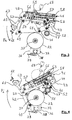
- the coil 22 is unwound thanks to a drive device 41 mounted in the module 27.
- Each coil 22 is rotated and unwound by one or more devices 41, this number being a function of the width of the coil 22.
- the device or devices 41 can pass from an inactive position without coming into contact and therefore without driving the coil 22 ( Figure 3 ) at an active position engaged with the coil 22 ( Figure 4 ), and reciprocally.
- each stage 33 is designed to support at least one coil 22
- each stage 33 is equipped with at least one device 41.
- Devices 41 can be placed stored in an inactive position (represented for example in FIG. Figure 2 on the left side, against the side wall 32).
- the device 41 is positioned above the coil 22 to be driven.
- the device 41 comprises a structure 42 with two lateral flanges.
- the structure 42 has a lower cutout allowing the passage of the coil to be unrolled 22.
- Each stage 33 of the module 27 comprises a bar 43 similar to a horizontal spacer between the two walls 32.
- the bar 43 is positioned substantially towards the front of the module 27.
- the bar 43 is parallel to and is located above the transom 38.
- At least one device 41 is attached to the bar 43.
- the device 41 is slidably mounted on the bar 43, to be positioned and locked by the operator precisely according to the position of the coil 22 and so as to be able to drive it.
- a front portion of the structure 42 preferably has a fastener 44.
- the fastener 44 has a rounded concave shape.
- the fastener 44 is complementary to the round profile of the bar 43 and locks the device 41 on the bar 43, while allowing a tilting.
- the structure 42, and thus the device 41 are perpendicular to the bar 43.
- the device 41 moves from the inactive position to the active position by pivoting backwards and downwards relative to the bar 43 (arrow Pa Figure 3 ). Conversely, the device 41 moves from the active position to the inactive position by pivoting forwards and upwards relative to the bar 43 (Arrow Pi in Figure 4 ).
- the device 41 comprises an endless drive belt 46.
- the belt 46 is held by the structure 42 in a path defined by a set of eight rollers. When the device 41 is in the inactive position, the belt 46 is in an inactive configuration. When the device 41 is in the active position, the belt 46 is in an active configuration.
- the belt 46 is driven in scrolling by means of drive means present at the module 27.
- the drive means are a feed shaft or rotary drive shaft 47.
- the belt 46 is not trained ( Figure 3 ).
- the belt 46 comes into contact and is driven by friction against the drive shaft 47 ( Figure 4 ).
- Each stage 33 of the module 27 comprises a drive shaft 47.
- the drive shaft 47 is positioned substantially towards the front of the module 27, between the crossmember 38 and the bar 43.
- the driving axis 47 is parallel at the crossmember 38 and the bar 43.
- the drive shaft 47 is located between the crossmember 38 and the bar 43.
- the structure 42, and thus the device 41 are perpendicular to the drive axis 47.
- the drive shaft 47 is divided into two axis segments (not visible in the Figures), each of the two segments being rotated by a separate motor and its associated belt 48.
- Each stage 33 of the module 27 thus comprises two 48.
- These two segments of axis 47 can drive at different speeds at least two devices 41 present at the same stage 33 of the module 27.
- the speed of the motors 48 is regulated according to the layout of the sheet 8.
- the device 41 comprises eight rollers pivotally mounted on the structure 42.
- a rear lower roller 49 and a central lower roller 51 make it possible to guide and maintain the belt 46 in contact with a portion of a peripheral circumferential surface of the coil 22.
- the device 41 rests on the coil 22 through the belt 46.
- the device 41 rocker (arrow Pa) relative to the bar 43 throughout the course of the coil 22.
- the lower central roller 51 and a lower front roller 52 make it possible to guide and maintain the belt 46 in contact with a portion of a circumferential peripheral surface of the drive shaft 47.
- the belt 46 In its inactive configuration, the belt 46 has a substantially rectilinear path between the rear lower roller 49 and the central lower roller 51 and between this same central lower roller 51 and the lower lower roller 52 ( Figure 3 ).
- the belt 46 In the active configuration of the belt 46, the unwinding of the spool 22 is synchronized with the rotation of the drive spindle 47.
- the belt 46 has a curved path between the rear lower roller 49 and the roller lower central 51 by marrying the portion of the peripheral circumferential surface of the In the active configuration, the belt 46 has a curved path between the lower central roller 51 and the lower front roller 52 conforming to the portion of the peripheral circumferential surface of the drive shaft 47 (FIG. Figure 4 ).
- the belt 46 follows a path guided and maintained by four other upper rollers 53.
- a movable roller 54 completes the path of the belt 46, forming a variable length loop with two of the upper rollers 53.
- the movable roller 54 is pivotally mounted on a sliding slide 56.
- the slide 56 slides in a slot 57.
- the slot is formed between the front and the rear of the structure 42.
- the slider 56 associated with the movable roller 54, serves to compensate variations in the length of the path of the belt 46, when it moves from the inactive configuration to substantially rectilinear path to the active configuration curved path.
- the slider 56 When the path is rectilinear and therefore short, the slider 56 is in the forward position, so that a distance between two of the upper rollers 53 and the movable roller 54 is large (di Figure 3 ), the length of the belt 46 remaining constant. When the path is curved and thus lengthened, the slide 56 is in the rear position, so that the distance between two of the upper rollers 53 and the movable roller 54 is short (da Figure 4 ), the length of the belt 46 remaining constant.
- the device 41 comprises return means, fixed to the slide 56 and thus to the moving roller 54.
- the return means maintain the belt 46 in tension in the inactive configuration and in the active configuration. In the active configuration, the return means allow the belt 46 to conform to the portion of the peripheral circumferential surface and therefore to the decreasing diameter of the coil 22 as the latter proceeds.
- the return means are means able to be actuated and disengaged to move the belt 46 from the inactive configuration to the active configuration and vice versa.
- the return means are in the form of a jack 58, for example a pneumatic jack.
- the jack 58 is oriented substantially from front to rear, parallel to the slot 57.
- the jack 58 is fixed to the structure 42 above the slot 57.
- the free end of the rod 59 of the piston of the jack 58 is fixed to the front part of the slide 56.
- the rod 59 of the piston the cylinder 58 retracts simultaneously from the rear to the front (Arrow Sa in Figure 3 )
- the slider 56 passes from the rear to the front, which causes the belt 46 to move to the active configuration.
- the rod 59 of the piston of the jack 58 deploys simultaneously from the front to the rear (Arrow Si in Figure 4 ), the slide 56 passes from the front to the rear, which causes the belt 46 to go into the inactive configuration.
- Each stage 33 of the module 27 comprises a ramp 61 similar to a horizontal spacer between the two walls 32.
- the ramp 61 is positioned substantially towards the rear of the module 27.
- the ramp 61 is parallel to the drive axis 47, the crossbar 38 and the bar 43.
- the ramp 61 is located substantially at the same height as the driving axis 47.
- At least one device 41 is secured to the ramp 61.
- the structure 42, and thus the device 41 are perpendicular to the ramp 61.
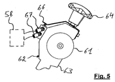
- the device 41 is secured to the ramp 61 both in its inactive raised position and in its lowered active position. To do this, the device 41 preferably comprises securing means 62 (see FIG. Figure 5 ).
- the securing means comprise an arm 63.
- the arm 63 projects towards the rear of the structure 42 of the device 41.
- a front end of the arm 63 is held in the structure 42 of the device 41 while allowing pivoting .
- the arm 63 is pivotable between a low inclination in the raised inactive position and a high inclination in the lowered active position.
- a rear end of the arm 63 has a rounded concave shape similar to a hook. This form is complementary to the round profile of the ramp 61, which allows the arm 63 to remain attached to the ramp 61, regardless of the tilted position of the device 41. Thanks to such a connection, the arm 63 is mounted to slide on the bar 43, to be positioned and secured by the operator precisely, following the position of the device 41 on the bar 43.
- the securing means 62 advantageously comprise a gripping member 64.
- the gripping member 64 is provided at the rear end of the arm 63.
- the gripping member 64 is here a gripping handle turned by the operator. The handle 64 moves a screw so as to secure the device 41 and maintain it on the ramp 61.
- the securing means 62 advantageously comprise an actuator 66 connected to the return means, that is to say in this case to the jack 58.
- the actuator 66 is in the form of a pusher and is mechanically connected to the handle 64.
- the actuator 66 acts on two valves 67 which are in pneumatic connection with the jack 58 by means of a pneumatically actuated valve (not visible in the figures).
- the operator first places the metallized strip coil 13 with the coil support 34 on the crosspiece 38, according to the layout of the sheet 8. Then, the operator moves the device 41 on the bar 43 and positions it so that the belt 46 is centered with respect to the width of the coil 22. If the width of the metallized strip 13 is large, and therefore if the width of the coil 22 is large, the operator shifts the first device 41 and adds a second device 41 next to the first.
- the operator lowers the device 41, by rocking the structure 42 relative to the bar 43 and by pivoting the arm 63 relative to the structure 42, so that the belt 46 comes into engagement with the axis of drive 47 and with the coil 22.
- the biased biasing means pneumatic jack 58 the operator does not have to force to pass the belt 46 from its inactive configuration to its active configuration.
- the return means 58 being disengaged, the slider 56 and the movable roller 54 move easily.
- the operator rotates the handle 64 in one direction, it simultaneously secures the device 41 to the ramp 61, and it actuates the cylinder 58 by causing it to engage.
- the belt 46 is tensioned against the reel 22 to be unrolled.
- Each stage 33 of the module 27 preferably comprises a compressed air distribution channel in the form of a tube 68.
- the tube 68 is positioned substantially towards the middle of the module 27 and above the device 41.
- the tube 68 is parallel to the drive shaft 47, the cross member 38, the bar 43 and the ramp 61.
- the tube 68 is connected to the pneumatic cylinder 58 of the device 41, via the pneumatic valve.
- the tube 68 supplies one or more devices 41 of the stage 33.
- the devices 41 can be easily and quickly positioned, then connected, or disconnected, then stored aside, without creating any inconvenience.
- the return means 58 may be replaced by an electrically actuated linear motor.
- the device or devices 41 can be integrated in the supply and recovery station of tape 6.
Landscapes
- Replacement Of Web Rolls (AREA)
- Advancing Webs (AREA)
- Unwinding Webs (AREA)
- Labeling Devices (AREA)
- Auxiliary Devices For And Details Of Packaging Control (AREA)
Priority Applications (1)
| Application Number | Priority Date | Filing Date | Title |
|---|---|---|---|
| EP13712687.6A EP2834177B1 (fr) | 2012-04-04 | 2013-03-21 | Dispositif d'entraînement pour bande à estamper, module dérouleur et machine d'estampage ainsi équipée |
Applications Claiming Priority (3)
| Application Number | Priority Date | Filing Date | Title |
|---|---|---|---|
| EP12002436 | 2012-04-04 | ||
| EP13712687.6A EP2834177B1 (fr) | 2012-04-04 | 2013-03-21 | Dispositif d'entraînement pour bande à estamper, module dérouleur et machine d'estampage ainsi équipée |
| PCT/EP2013/000849 WO2013149703A1 (fr) | 2012-04-04 | 2013-03-21 | Dispositif d'entraînement pour bande à estamper, module dérouleur et machine d'estampage ainsi équipée |
Publications (2)
| Publication Number | Publication Date |
|---|---|
| EP2834177A1 EP2834177A1 (fr) | 2015-02-11 |
| EP2834177B1 true EP2834177B1 (fr) | 2016-06-01 |
Family
ID=48013913
Family Applications (1)
| Application Number | Title | Priority Date | Filing Date |
|---|---|---|---|
| EP13712687.6A Active EP2834177B1 (fr) | 2012-04-04 | 2013-03-21 | Dispositif d'entraînement pour bande à estamper, module dérouleur et machine d'estampage ainsi équipée |
Country Status (9)
Families Citing this family (6)
| Publication number | Priority date | Publication date | Assignee | Title |
|---|---|---|---|---|
| US10759154B2 (en) | 2018-02-08 | 2020-09-01 | Hewlett-Packard Development Company, L.P. | Foil deposition |
| EP3781402B1 (en) * | 2018-04-20 | 2024-05-29 | Bobst Mex Sa | Device for driving a stamping foil, stamping station and machine, and method for controlling the driving of a stamping foil |
| TWI718698B (zh) | 2018-10-29 | 2021-02-11 | 瑞士商巴柏斯特麥克斯合資公司 | 全像箔供給裝置以及燙金印刷機 |
| CN113613907B (zh) * | 2019-03-20 | 2023-06-09 | 鲍勃斯脱梅克斯股份有限公司 | 热箔压印机 |
| CN110816039A (zh) * | 2019-08-23 | 2020-02-21 | 浙江澳饰实业有限公司 | 皮革图案的烫印机 |
| EP4082792A4 (en) * | 2019-12-27 | 2024-01-24 | Brother Kogyo Kabushiki Kaisha | FILM TRANSFER FILM CASSETTE AND FILM TRANSFER APPARATUS |
Family Cites Families (19)
| Publication number | Priority date | Publication date | Assignee | Title |
|---|---|---|---|---|
| US2342203A (en) * | 1941-04-17 | 1944-02-22 | John B Kohler | Device for feeding web material |
| US2892597A (en) * | 1957-04-04 | 1959-06-30 | Fred A Schmidt | Tension control for web printing machines |
| US3740296A (en) * | 1971-05-10 | 1973-06-19 | John Motter Printing Press Co | Automatic splicing rollstand |
| US4893763A (en) * | 1987-12-22 | 1990-01-16 | Roll Systems, Inc. | Roll support and feed apparatus |
| DE4028536A1 (de) * | 1990-02-01 | 1992-03-12 | Aristo Graphic Systeme | Vorrichtung zur be- oder verarbeitung einer materialbahn |
| IT1269115B (it) * | 1994-06-16 | 1997-03-21 | Perini Fabio Spa | Dispositivo per il cambio automatico di bobine di materiale nastriforme |
| IT238735Y1 (it) * | 1995-04-21 | 2000-11-13 | Perini Fabio Spa | Svolgitore per bobine di materiale nastriforme con sistema dicontrollo della pressione di svolgimento |
| FR2775633B1 (fr) * | 1998-03-09 | 2000-04-14 | Breger Emballages Sa | Installation d'impression par transfert, notamment par dorure |
| US6387201B1 (en) * | 1999-05-14 | 2002-05-14 | Best Cutting Die Company | Rotary hot foil stamping machine |
| JP2002053115A (ja) * | 2000-08-09 | 2002-02-19 | Lintec Corp | ラベル貼り付け装置 |
| BR0215944A (pt) * | 2002-11-13 | 2005-08-09 | Perini Fabio Spa | Dispositivo de desenrolamento para carretéis de material em tela com mecanismo de acionamento duplo e método de desenrolamento relacionado |
| ITFI20030064A1 (it) * | 2003-03-13 | 2004-09-14 | Perini Fabio Spa | Dispositivo svolgitore automatico e continuo per erogare |
| TWI283650B (en) * | 2004-04-23 | 2007-07-11 | Bobst Sa | Module for supporting and driving a wound foil matter for a machine processing it |
| ATE472501T1 (de) * | 2004-04-23 | 2010-07-15 | Bobst Sa | Trag- und antriebsmodul eines aufgespulten bahnförmigen materials für eine bearbeitungsmaschine |
| US7344104B2 (en) * | 2005-04-08 | 2008-03-18 | Kimberly-Clark Worldwide, Inc. | Unwind apparatus |
| ITFI20060061A1 (it) * | 2006-03-03 | 2007-09-04 | Futura Spa | Dispositivo e metodo per la movimentazione delle bobine in uno svolgitore |
| EP2197773A4 (en) * | 2007-09-17 | 2011-01-19 | 3M Innovative Properties Co | DOUBLE RIBBON APPLICATOR |
| JP2009280316A (ja) * | 2008-05-20 | 2009-12-03 | Lintec Corp | 張力付与装置及びシート貼付装置 |
| IT1399946B1 (it) * | 2010-04-29 | 2013-05-09 | Clevertech Srl | Dispositivo di avvolgimento di un nastro. |
-
2013
- 2013-03-21 KR KR1020147030770A patent/KR101521070B1/ko not_active Expired - Fee Related
- 2013-03-21 BR BR112014024763-3A patent/BR112014024763B1/pt not_active IP Right Cessation
- 2013-03-21 CN CN201380028935.4A patent/CN104334482B/zh active Active
- 2013-03-21 US US14/390,618 patent/US9656455B2/en active Active
- 2013-03-21 JP JP2015503777A patent/JP6306567B2/ja active Active
- 2013-03-21 EP EP13712687.6A patent/EP2834177B1/fr active Active
- 2013-03-21 ES ES13712687.6T patent/ES2579347T3/es active Active
- 2013-03-21 WO PCT/EP2013/000849 patent/WO2013149703A1/fr active Application Filing
- 2013-03-26 TW TW102110634A patent/TWI597229B/zh not_active IP Right Cessation
Non-Patent Citations (1)
| Title |
|---|
| None * |
Also Published As
| Publication number | Publication date |
|---|---|
| US20150075394A1 (en) | 2015-03-19 |
| KR101521070B1 (ko) | 2015-05-15 |
| KR20140134341A (ko) | 2014-11-21 |
| TW201343524A (zh) | 2013-11-01 |
| BR112014024763B1 (pt) | 2020-11-24 |
| CN104334482A (zh) | 2015-02-04 |
| JP2015520043A (ja) | 2015-07-16 |
| TWI597229B (zh) | 2017-09-01 |
| CN104334482B (zh) | 2018-03-27 |
| EP2834177A1 (fr) | 2015-02-11 |
| US9656455B2 (en) | 2017-05-23 |
| WO2013149703A1 (fr) | 2013-10-10 |
| JP6306567B2 (ja) | 2018-04-04 |
| ES2579347T3 (es) | 2016-08-10 |
Similar Documents
| Publication | Publication Date | Title |
|---|---|---|
| EP2834177B1 (fr) | Dispositif d'entraînement pour bande à estamper, module dérouleur et machine d'estampage ainsi équipée | |
| EP2616243B1 (fr) | Dispositif d'impression par estampage | |
| EP3003703B1 (fr) | Unite de transformation d'un support en bande continue et machine de production d'emballages ainsi equipee | |
| FR2612879A1 (fr) | Appareil d'alimentation en un materiau sous forme de film | |
| EP2616242B1 (fr) | Dispositif de guidage de bandes pour machine d'estampage | |
| JP5222318B2 (ja) | 搬送装置 | |
| WO2010102783A1 (fr) | Dispositif de transfert pour support plan dans une machine de production d'emballages | |
| EP2704973B1 (fr) | Dispositif d'empilage de feuilles de papier ou similaire | |
| EP0741096B1 (fr) | Dispositif de transport de bandes métallisées | |
| FR2484979A1 (fr) | Procede et appareil d'assemblage de matiere en feuille, notamment pour alimenter en continu des imprimantes rapides | |
| EP1393903B1 (fr) | Presse rotative pour rapporter des motifs sur un substrat en bande | |
| CN112654571B (zh) | 用于展开带材的装置及印压元件成片材形式的机器 | |
| WO2013164075A1 (fr) | Machine de traitement d'elements en plaque avec table de marge munie de moyens de transport | |
| JP6156839B2 (ja) | 帯掛け包装装置 | |
| EP2613943B1 (fr) | Procede d'introduction de bandes a estamper dans un systeme assurant leur defilement et dispositif de mise en oeuvre d'un tel procede | |
| EP1588968B1 (fr) | Module de support et d'entraînement d'une matière en bande bobinée pour une machine la travaillant | |
| BE889349A (fr) | Procede et appareil d'assemblage de matiere en feuille, notamment pour alimenter en continu des imprimantes rapides | |
| EP0741095B1 (fr) | Dispositif de chargement de bandes métallisées dans une machine de transfert d'image métallisées sur des éléments en plaque | |
| CN210551422U (zh) | 一种包装材料切割装置的切刀往复驱动机构 | |
| FR2870782A1 (fr) | Machine d'impression d'une bande |
Legal Events
| Date | Code | Title | Description |
|---|---|---|---|
| PUAI | Public reference made under article 153(3) epc to a published international application that has entered the european phase |
Free format text: ORIGINAL CODE: 0009012 |
|
| 17P | Request for examination filed |
Effective date: 20141103 |
|
| AK | Designated contracting states |
Kind code of ref document: A1 Designated state(s): AL AT BE BG CH CY CZ DE DK EE ES FI FR GB GR HR HU IE IS IT LI LT LU LV MC MK MT NL NO PL PT RO RS SE SI SK SM TR |
|
| AX | Request for extension of the european patent |
Extension state: BA ME |
|
| DAX | Request for extension of the european patent (deleted) | ||
| REG | Reference to a national code |
Ref country code: DE Ref legal event code: R079 Ref document number: 602013008207 Country of ref document: DE Free format text: PREVIOUS MAIN CLASS: B65H0016100000 Ipc: B41F0019020000 |
|
| RIC1 | Information provided on ipc code assigned before grant |
Ipc: B26F 1/40 20060101ALI20151218BHEP Ipc: B65H 18/14 20060101ALI20151218BHEP Ipc: B41F 19/02 20060101AFI20151218BHEP Ipc: B65H 16/10 20060101ALI20151218BHEP Ipc: B41F 19/06 20060101ALI20151218BHEP Ipc: B65H 20/06 20060101ALI20151218BHEP |
|
| GRAP | Despatch of communication of intention to grant a patent |
Free format text: ORIGINAL CODE: EPIDOSNIGR1 |
|
| INTG | Intention to grant announced |
Effective date: 20160219 |
|
| GRAS | Grant fee paid |
Free format text: ORIGINAL CODE: EPIDOSNIGR3 |
|
| GRAA | (expected) grant |
Free format text: ORIGINAL CODE: 0009210 |
|
| AK | Designated contracting states |
Kind code of ref document: B1 Designated state(s): AL AT BE BG CH CY CZ DE DK EE ES FI FR GB GR HR HU IE IS IT LI LT LU LV MC MK MT NL NO PL PT RO RS SE SI SK SM TR |
|
| REG | Reference to a national code |
Ref country code: GB Ref legal event code: FG4D Free format text: NOT ENGLISH |
|
| REG | Reference to a national code |
Ref country code: CH Ref legal event code: EP Ref country code: AT Ref legal event code: REF Ref document number: 803635 Country of ref document: AT Kind code of ref document: T Effective date: 20160615 |
|
| REG | Reference to a national code |
Ref country code: IE Ref legal event code: FG4D Free format text: LANGUAGE OF EP DOCUMENT: FRENCH |
|
| REG | Reference to a national code |
Ref country code: DE Ref legal event code: R096 Ref document number: 602013008207 Country of ref document: DE |
|
| REG | Reference to a national code |
Ref country code: ES Ref legal event code: FG2A Ref document number: 2579347 Country of ref document: ES Kind code of ref document: T3 Effective date: 20160810 |
|
| REG | Reference to a national code |
Ref country code: LT Ref legal event code: MG4D |
|
| REG | Reference to a national code |
Ref country code: NL Ref legal event code: MP Effective date: 20160601 |
|
| PG25 | Lapsed in a contracting state [announced via postgrant information from national office to epo] |
Ref country code: LT Free format text: LAPSE BECAUSE OF FAILURE TO SUBMIT A TRANSLATION OF THE DESCRIPTION OR TO PAY THE FEE WITHIN THE PRESCRIBED TIME-LIMIT Effective date: 20160601 Ref country code: FI Free format text: LAPSE BECAUSE OF FAILURE TO SUBMIT A TRANSLATION OF THE DESCRIPTION OR TO PAY THE FEE WITHIN THE PRESCRIBED TIME-LIMIT Effective date: 20160601 Ref country code: NO Free format text: LAPSE BECAUSE OF FAILURE TO SUBMIT A TRANSLATION OF THE DESCRIPTION OR TO PAY THE FEE WITHIN THE PRESCRIBED TIME-LIMIT Effective date: 20160901 |
|
| REG | Reference to a national code |
Ref country code: AT Ref legal event code: MK05 Ref document number: 803635 Country of ref document: AT Kind code of ref document: T Effective date: 20160601 |
|
| PG25 | Lapsed in a contracting state [announced via postgrant information from national office to epo] |
Ref country code: SE Free format text: LAPSE BECAUSE OF FAILURE TO SUBMIT A TRANSLATION OF THE DESCRIPTION OR TO PAY THE FEE WITHIN THE PRESCRIBED TIME-LIMIT Effective date: 20160601 Ref country code: GR Free format text: LAPSE BECAUSE OF FAILURE TO SUBMIT A TRANSLATION OF THE DESCRIPTION OR TO PAY THE FEE WITHIN THE PRESCRIBED TIME-LIMIT Effective date: 20160902 Ref country code: HR Free format text: LAPSE BECAUSE OF FAILURE TO SUBMIT A TRANSLATION OF THE DESCRIPTION OR TO PAY THE FEE WITHIN THE PRESCRIBED TIME-LIMIT Effective date: 20160601 Ref country code: RS Free format text: LAPSE BECAUSE OF FAILURE TO SUBMIT A TRANSLATION OF THE DESCRIPTION OR TO PAY THE FEE WITHIN THE PRESCRIBED TIME-LIMIT Effective date: 20160601 Ref country code: NL Free format text: LAPSE BECAUSE OF FAILURE TO SUBMIT A TRANSLATION OF THE DESCRIPTION OR TO PAY THE FEE WITHIN THE PRESCRIBED TIME-LIMIT Effective date: 20160601 Ref country code: LV Free format text: LAPSE BECAUSE OF FAILURE TO SUBMIT A TRANSLATION OF THE DESCRIPTION OR TO PAY THE FEE WITHIN THE PRESCRIBED TIME-LIMIT Effective date: 20160601 |
|
| PG25 | Lapsed in a contracting state [announced via postgrant information from national office to epo] |
Ref country code: EE Free format text: LAPSE BECAUSE OF FAILURE TO SUBMIT A TRANSLATION OF THE DESCRIPTION OR TO PAY THE FEE WITHIN THE PRESCRIBED TIME-LIMIT Effective date: 20160601 Ref country code: CZ Free format text: LAPSE BECAUSE OF FAILURE TO SUBMIT A TRANSLATION OF THE DESCRIPTION OR TO PAY THE FEE WITHIN THE PRESCRIBED TIME-LIMIT Effective date: 20160601 Ref country code: RO Free format text: LAPSE BECAUSE OF FAILURE TO SUBMIT A TRANSLATION OF THE DESCRIPTION OR TO PAY THE FEE WITHIN THE PRESCRIBED TIME-LIMIT Effective date: 20160601 Ref country code: IS Free format text: LAPSE BECAUSE OF FAILURE TO SUBMIT A TRANSLATION OF THE DESCRIPTION OR TO PAY THE FEE WITHIN THE PRESCRIBED TIME-LIMIT Effective date: 20161001 Ref country code: SK Free format text: LAPSE BECAUSE OF FAILURE TO SUBMIT A TRANSLATION OF THE DESCRIPTION OR TO PAY THE FEE WITHIN THE PRESCRIBED TIME-LIMIT Effective date: 20160601 |
|
| PG25 | Lapsed in a contracting state [announced via postgrant information from national office to epo] |
Ref country code: SM Free format text: LAPSE BECAUSE OF FAILURE TO SUBMIT A TRANSLATION OF THE DESCRIPTION OR TO PAY THE FEE WITHIN THE PRESCRIBED TIME-LIMIT Effective date: 20160601 Ref country code: AT Free format text: LAPSE BECAUSE OF FAILURE TO SUBMIT A TRANSLATION OF THE DESCRIPTION OR TO PAY THE FEE WITHIN THE PRESCRIBED TIME-LIMIT Effective date: 20160601 Ref country code: PL Free format text: LAPSE BECAUSE OF FAILURE TO SUBMIT A TRANSLATION OF THE DESCRIPTION OR TO PAY THE FEE WITHIN THE PRESCRIBED TIME-LIMIT Effective date: 20160601 Ref country code: PT Free format text: LAPSE BECAUSE OF FAILURE TO SUBMIT A TRANSLATION OF THE DESCRIPTION OR TO PAY THE FEE WITHIN THE PRESCRIBED TIME-LIMIT Effective date: 20161003 |
|
| REG | Reference to a national code |
Ref country code: DE Ref legal event code: R097 Ref document number: 602013008207 Country of ref document: DE |
|
| REG | Reference to a national code |
Ref country code: FR Ref legal event code: PLFP Year of fee payment: 5 |
|
| PLBE | No opposition filed within time limit |
Free format text: ORIGINAL CODE: 0009261 |
|
| STAA | Information on the status of an ep patent application or granted ep patent |
Free format text: STATUS: NO OPPOSITION FILED WITHIN TIME LIMIT |
|
| 26N | No opposition filed |
Effective date: 20170302 |
|
| PG25 | Lapsed in a contracting state [announced via postgrant information from national office to epo] |
Ref country code: DK Free format text: LAPSE BECAUSE OF FAILURE TO SUBMIT A TRANSLATION OF THE DESCRIPTION OR TO PAY THE FEE WITHIN THE PRESCRIBED TIME-LIMIT Effective date: 20160601 Ref country code: SI Free format text: LAPSE BECAUSE OF FAILURE TO SUBMIT A TRANSLATION OF THE DESCRIPTION OR TO PAY THE FEE WITHIN THE PRESCRIBED TIME-LIMIT Effective date: 20160601 |
|
| PG25 | Lapsed in a contracting state [announced via postgrant information from national office to epo] |
Ref country code: MC Free format text: LAPSE BECAUSE OF FAILURE TO SUBMIT A TRANSLATION OF THE DESCRIPTION OR TO PAY THE FEE WITHIN THE PRESCRIBED TIME-LIMIT Effective date: 20160601 |
|
| REG | Reference to a national code |
Ref country code: IE Ref legal event code: MM4A |
|
| PG25 | Lapsed in a contracting state [announced via postgrant information from national office to epo] |
Ref country code: LU Free format text: LAPSE BECAUSE OF NON-PAYMENT OF DUE FEES Effective date: 20170321 |
|
| PG25 | Lapsed in a contracting state [announced via postgrant information from national office to epo] |
Ref country code: IE Free format text: LAPSE BECAUSE OF NON-PAYMENT OF DUE FEES Effective date: 20170321 |
|
| REG | Reference to a national code |
Ref country code: BE Ref legal event code: MM Effective date: 20170331 |
|
| REG | Reference to a national code |
Ref country code: FR Ref legal event code: PLFP Year of fee payment: 6 |
|
| PG25 | Lapsed in a contracting state [announced via postgrant information from national office to epo] |
Ref country code: BE Free format text: LAPSE BECAUSE OF NON-PAYMENT OF DUE FEES Effective date: 20170331 |
|
| PG25 | Lapsed in a contracting state [announced via postgrant information from national office to epo] |
Ref country code: MT Free format text: LAPSE BECAUSE OF FAILURE TO SUBMIT A TRANSLATION OF THE DESCRIPTION OR TO PAY THE FEE WITHIN THE PRESCRIBED TIME-LIMIT Effective date: 20160601 |
|
| PG25 | Lapsed in a contracting state [announced via postgrant information from national office to epo] |
Ref country code: AL Free format text: LAPSE BECAUSE OF FAILURE TO SUBMIT A TRANSLATION OF THE DESCRIPTION OR TO PAY THE FEE WITHIN THE PRESCRIBED TIME-LIMIT Effective date: 20160601 |
|
| PG25 | Lapsed in a contracting state [announced via postgrant information from national office to epo] |
Ref country code: HU Free format text: LAPSE BECAUSE OF FAILURE TO SUBMIT A TRANSLATION OF THE DESCRIPTION OR TO PAY THE FEE WITHIN THE PRESCRIBED TIME-LIMIT; INVALID AB INITIO Effective date: 20130321 |
|
| PG25 | Lapsed in a contracting state [announced via postgrant information from national office to epo] |
Ref country code: BG Free format text: LAPSE BECAUSE OF FAILURE TO SUBMIT A TRANSLATION OF THE DESCRIPTION OR TO PAY THE FEE WITHIN THE PRESCRIBED TIME-LIMIT Effective date: 20160601 |
|
| PG25 | Lapsed in a contracting state [announced via postgrant information from national office to epo] |
Ref country code: CY Free format text: LAPSE BECAUSE OF FAILURE TO SUBMIT A TRANSLATION OF THE DESCRIPTION OR TO PAY THE FEE WITHIN THE PRESCRIBED TIME-LIMIT Effective date: 20160601 |
|
| PG25 | Lapsed in a contracting state [announced via postgrant information from national office to epo] |
Ref country code: MK Free format text: LAPSE BECAUSE OF FAILURE TO SUBMIT A TRANSLATION OF THE DESCRIPTION OR TO PAY THE FEE WITHIN THE PRESCRIBED TIME-LIMIT Effective date: 20160601 |
|
| PG25 | Lapsed in a contracting state [announced via postgrant information from national office to epo] |
Ref country code: TR Free format text: LAPSE BECAUSE OF FAILURE TO SUBMIT A TRANSLATION OF THE DESCRIPTION OR TO PAY THE FEE WITHIN THE PRESCRIBED TIME-LIMIT Effective date: 20160601 |
|
| PGFP | Annual fee paid to national office [announced via postgrant information from national office to epo] |
Ref country code: DE Payment date: 20241231 Year of fee payment: 13 |
|
| PGFP | Annual fee paid to national office [announced via postgrant information from national office to epo] |
Ref country code: FR Payment date: 20250312 Year of fee payment: 13 |
|
| PGFP | Annual fee paid to national office [announced via postgrant information from national office to epo] |
Ref country code: IT Payment date: 20250211 Year of fee payment: 13 Ref country code: GB Payment date: 20250102 Year of fee payment: 13 |
|
| PGFP | Annual fee paid to national office [announced via postgrant information from national office to epo] |
Ref country code: ES Payment date: 20250404 Year of fee payment: 13 |
|
| PGFP | Annual fee paid to national office [announced via postgrant information from national office to epo] |
Ref country code: CH Payment date: 20250401 Year of fee payment: 13 |