EP2833826B1 - Composite prosthetic devices - Google Patents
Composite prosthetic devices Download PDFInfo
- Publication number
- EP2833826B1 EP2833826B1 EP13772707.9A EP13772707A EP2833826B1 EP 2833826 B1 EP2833826 B1 EP 2833826B1 EP 13772707 A EP13772707 A EP 13772707A EP 2833826 B1 EP2833826 B1 EP 2833826B1
- Authority
- EP
- European Patent Office
- Prior art keywords
- electrospun
- polymer
- layer
- composite
- tetrafluoroethylene
- Prior art date
- Legal status (The legal status is an assumption and is not a legal conclusion. Google has not performed a legal analysis and makes no representation as to the accuracy of the status listed.)
- Active
Links
Images


Classifications
-
- A—HUMAN NECESSITIES
- A61—MEDICAL OR VETERINARY SCIENCE; HYGIENE
- A61F—FILTERS IMPLANTABLE INTO BLOOD VESSELS; PROSTHESES; DEVICES PROVIDING PATENCY TO, OR PREVENTING COLLAPSING OF, TUBULAR STRUCTURES OF THE BODY, e.g. STENTS; ORTHOPAEDIC, NURSING OR CONTRACEPTIVE DEVICES; FOMENTATION; TREATMENT OR PROTECTION OF EYES OR EARS; BANDAGES, DRESSINGS OR ABSORBENT PADS; FIRST-AID KITS
- A61F2/00—Filters implantable into blood vessels; Prostheses, i.e. artificial substitutes or replacements for parts of the body; Appliances for connecting them with the body; Devices providing patency to, or preventing collapsing of, tubular structures of the body, e.g. stents
- A61F2/0077—Special surfaces of prostheses, e.g. for improving ingrowth
-
- A—HUMAN NECESSITIES
- A61—MEDICAL OR VETERINARY SCIENCE; HYGIENE
- A61F—FILTERS IMPLANTABLE INTO BLOOD VESSELS; PROSTHESES; DEVICES PROVIDING PATENCY TO, OR PREVENTING COLLAPSING OF, TUBULAR STRUCTURES OF THE BODY, e.g. STENTS; ORTHOPAEDIC, NURSING OR CONTRACEPTIVE DEVICES; FOMENTATION; TREATMENT OR PROTECTION OF EYES OR EARS; BANDAGES, DRESSINGS OR ABSORBENT PADS; FIRST-AID KITS
- A61F2/00—Filters implantable into blood vessels; Prostheses, i.e. artificial substitutes or replacements for parts of the body; Appliances for connecting them with the body; Devices providing patency to, or preventing collapsing of, tubular structures of the body, e.g. stents
- A61F2/02—Prostheses implantable into the body
- A61F2/04—Hollow or tubular parts of organs, e.g. bladders, tracheae, bronchi or bile ducts
- A61F2/06—Blood vessels
- A61F2/07—Stent-grafts
-
- A—HUMAN NECESSITIES
- A61—MEDICAL OR VETERINARY SCIENCE; HYGIENE
- A61F—FILTERS IMPLANTABLE INTO BLOOD VESSELS; PROSTHESES; DEVICES PROVIDING PATENCY TO, OR PREVENTING COLLAPSING OF, TUBULAR STRUCTURES OF THE BODY, e.g. STENTS; ORTHOPAEDIC, NURSING OR CONTRACEPTIVE DEVICES; FOMENTATION; TREATMENT OR PROTECTION OF EYES OR EARS; BANDAGES, DRESSINGS OR ABSORBENT PADS; FIRST-AID KITS
- A61F2/00—Filters implantable into blood vessels; Prostheses, i.e. artificial substitutes or replacements for parts of the body; Appliances for connecting them with the body; Devices providing patency to, or preventing collapsing of, tubular structures of the body, e.g. stents
- A61F2/82—Devices providing patency to, or preventing collapsing of, tubular structures of the body, e.g. stents
- A61F2/86—Stents in a form characterised by the wire-like elements; Stents in the form characterised by a net-like or mesh-like structure
-
- A—HUMAN NECESSITIES
- A61—MEDICAL OR VETERINARY SCIENCE; HYGIENE
- A61L—METHODS OR APPARATUS FOR STERILISING MATERIALS OR OBJECTS IN GENERAL; DISINFECTION, STERILISATION OR DEODORISATION OF AIR; CHEMICAL ASPECTS OF BANDAGES, DRESSINGS, ABSORBENT PADS OR SURGICAL ARTICLES; MATERIALS FOR BANDAGES, DRESSINGS, ABSORBENT PADS OR SURGICAL ARTICLES
- A61L31/00—Materials for other surgical articles, e.g. stents, stent-grafts, shunts, surgical drapes, guide wires, materials for adhesion prevention, occluding devices, surgical gloves, tissue fixation devices
- A61L31/08—Materials for coatings
- A61L31/10—Macromolecular materials
-
- A—HUMAN NECESSITIES
- A61—MEDICAL OR VETERINARY SCIENCE; HYGIENE
- A61L—METHODS OR APPARATUS FOR STERILISING MATERIALS OR OBJECTS IN GENERAL; DISINFECTION, STERILISATION OR DEODORISATION OF AIR; CHEMICAL ASPECTS OF BANDAGES, DRESSINGS, ABSORBENT PADS OR SURGICAL ARTICLES; MATERIALS FOR BANDAGES, DRESSINGS, ABSORBENT PADS OR SURGICAL ARTICLES
- A61L31/00—Materials for other surgical articles, e.g. stents, stent-grafts, shunts, surgical drapes, guide wires, materials for adhesion prevention, occluding devices, surgical gloves, tissue fixation devices
- A61L31/14—Materials characterised by their function or physical properties, e.g. injectable or lubricating compositions, shape-memory materials, surface modified materials
- A61L31/146—Porous materials, e.g. foams or sponges
-
- D—TEXTILES; PAPER
- D01—NATURAL OR MAN-MADE THREADS OR FIBRES; SPINNING
- D01D—MECHANICAL METHODS OR APPARATUS IN THE MANUFACTURE OF ARTIFICIAL FILAMENTS, THREADS, FIBRES, BRISTLES OR RIBBONS
- D01D10/00—Physical treatment of artificial filaments or the like during manufacture, i.e. during a continuous production process before the filaments have been collected
- D01D10/02—Heat treatment
-
- D—TEXTILES; PAPER
- D01—NATURAL OR MAN-MADE THREADS OR FIBRES; SPINNING
- D01D—MECHANICAL METHODS OR APPARATUS IN THE MANUFACTURE OF ARTIFICIAL FILAMENTS, THREADS, FIBRES, BRISTLES OR RIBBONS
- D01D5/00—Formation of filaments, threads, or the like
- D01D5/0007—Electro-spinning
- D01D5/0015—Electro-spinning characterised by the initial state of the material
- D01D5/003—Electro-spinning characterised by the initial state of the material the material being a polymer solution or dispersion
-
- D—TEXTILES; PAPER
- D01—NATURAL OR MAN-MADE THREADS OR FIBRES; SPINNING
- D01F—CHEMICAL FEATURES IN THE MANUFACTURE OF ARTIFICIAL FILAMENTS, THREADS, FIBRES, BRISTLES OR RIBBONS; APPARATUS SPECIALLY ADAPTED FOR THE MANUFACTURE OF CARBON FILAMENTS
- D01F6/00—Monocomponent artificial filaments or the like of synthetic polymers; Manufacture thereof
- D01F6/02—Monocomponent artificial filaments or the like of synthetic polymers; Manufacture thereof from homopolymers obtained by reactions only involving carbon-to-carbon unsaturated bonds
- D01F6/08—Monocomponent artificial filaments or the like of synthetic polymers; Manufacture thereof from homopolymers obtained by reactions only involving carbon-to-carbon unsaturated bonds from polymers of halogenated hydrocarbons
- D01F6/12—Monocomponent artificial filaments or the like of synthetic polymers; Manufacture thereof from homopolymers obtained by reactions only involving carbon-to-carbon unsaturated bonds from polymers of halogenated hydrocarbons from polymers of fluorinated hydrocarbons
-
- D—TEXTILES; PAPER
- D04—BRAIDING; LACE-MAKING; KNITTING; TRIMMINGS; NON-WOVEN FABRICS
- D04H—MAKING TEXTILE FABRICS, e.g. FROM FIBRES OR FILAMENTARY MATERIAL; FABRICS MADE BY SUCH PROCESSES OR APPARATUS, e.g. FELTS, NON-WOVEN FABRICS; COTTON-WOOL; WADDING ; NON-WOVEN FABRICS FROM STAPLE FIBRES, FILAMENTS OR YARNS, BONDED WITH AT LEAST ONE WEB-LIKE MATERIAL DURING THEIR CONSOLIDATION
- D04H1/00—Non-woven fabrics formed wholly or mainly of staple fibres or like relatively short fibres
- D04H1/70—Non-woven fabrics formed wholly or mainly of staple fibres or like relatively short fibres characterised by the method of forming fleeces or layers, e.g. reorientation of fibres
- D04H1/72—Non-woven fabrics formed wholly or mainly of staple fibres or like relatively short fibres characterised by the method of forming fleeces or layers, e.g. reorientation of fibres the fibres being randomly arranged
- D04H1/728—Non-woven fabrics formed wholly or mainly of staple fibres or like relatively short fibres characterised by the method of forming fleeces or layers, e.g. reorientation of fibres the fibres being randomly arranged by electro-spinning
-
- A—HUMAN NECESSITIES
- A61—MEDICAL OR VETERINARY SCIENCE; HYGIENE
- A61F—FILTERS IMPLANTABLE INTO BLOOD VESSELS; PROSTHESES; DEVICES PROVIDING PATENCY TO, OR PREVENTING COLLAPSING OF, TUBULAR STRUCTURES OF THE BODY, e.g. STENTS; ORTHOPAEDIC, NURSING OR CONTRACEPTIVE DEVICES; FOMENTATION; TREATMENT OR PROTECTION OF EYES OR EARS; BANDAGES, DRESSINGS OR ABSORBENT PADS; FIRST-AID KITS
- A61F2/00—Filters implantable into blood vessels; Prostheses, i.e. artificial substitutes or replacements for parts of the body; Appliances for connecting them with the body; Devices providing patency to, or preventing collapsing of, tubular structures of the body, e.g. stents
- A61F2/0077—Special surfaces of prostheses, e.g. for improving ingrowth
- A61F2002/0086—Special surfaces of prostheses, e.g. for improving ingrowth for preferentially controlling or promoting the growth of specific types of cells or tissues
-
- A—HUMAN NECESSITIES
- A61—MEDICAL OR VETERINARY SCIENCE; HYGIENE
- A61F—FILTERS IMPLANTABLE INTO BLOOD VESSELS; PROSTHESES; DEVICES PROVIDING PATENCY TO, OR PREVENTING COLLAPSING OF, TUBULAR STRUCTURES OF THE BODY, e.g. STENTS; ORTHOPAEDIC, NURSING OR CONTRACEPTIVE DEVICES; FOMENTATION; TREATMENT OR PROTECTION OF EYES OR EARS; BANDAGES, DRESSINGS OR ABSORBENT PADS; FIRST-AID KITS
- A61F2/00—Filters implantable into blood vessels; Prostheses, i.e. artificial substitutes or replacements for parts of the body; Appliances for connecting them with the body; Devices providing patency to, or preventing collapsing of, tubular structures of the body, e.g. stents
- A61F2/02—Prostheses implantable into the body
- A61F2/04—Hollow or tubular parts of organs, e.g. bladders, tracheae, bronchi or bile ducts
- A61F2/06—Blood vessels
- A61F2/07—Stent-grafts
- A61F2002/072—Encapsulated stents, e.g. wire or whole stent embedded in lining
-
- A—HUMAN NECESSITIES
- A61—MEDICAL OR VETERINARY SCIENCE; HYGIENE
- A61L—METHODS OR APPARATUS FOR STERILISING MATERIALS OR OBJECTS IN GENERAL; DISINFECTION, STERILISATION OR DEODORISATION OF AIR; CHEMICAL ASPECTS OF BANDAGES, DRESSINGS, ABSORBENT PADS OR SURGICAL ARTICLES; MATERIALS FOR BANDAGES, DRESSINGS, ABSORBENT PADS OR SURGICAL ARTICLES
- A61L2400/00—Materials characterised by their function or physical properties
- A61L2400/12—Nanosized materials, e.g. nanofibres, nanoparticles, nanowires, nanotubes; Nanostructured surfaces
-
- A—HUMAN NECESSITIES
- A61—MEDICAL OR VETERINARY SCIENCE; HYGIENE
- A61L—METHODS OR APPARATUS FOR STERILISING MATERIALS OR OBJECTS IN GENERAL; DISINFECTION, STERILISATION OR DEODORISATION OF AIR; CHEMICAL ASPECTS OF BANDAGES, DRESSINGS, ABSORBENT PADS OR SURGICAL ARTICLES; MATERIALS FOR BANDAGES, DRESSINGS, ABSORBENT PADS OR SURGICAL ARTICLES
- A61L2420/00—Materials or methods for coatings medical devices
- A61L2420/08—Coatings comprising two or more layers
-
- D—TEXTILES; PAPER
- D10—INDEXING SCHEME ASSOCIATED WITH SUBLASSES OF SECTION D, RELATING TO TEXTILES
- D10B—INDEXING SCHEME ASSOCIATED WITH SUBLASSES OF SECTION D, RELATING TO TEXTILES
- D10B2321/00—Fibres made from polymers obtained by reactions only involving carbon-to-carbon unsaturated bonds
- D10B2321/04—Fibres made from polymers obtained by reactions only involving carbon-to-carbon unsaturated bonds polymers of halogenated hydrocarbons
- D10B2321/042—Fibres made from polymers obtained by reactions only involving carbon-to-carbon unsaturated bonds polymers of halogenated hydrocarbons polymers of fluorinated hydrocarbons, e.g. polytetrafluoroethene [PTFE]
-
- D—TEXTILES; PAPER
- D10—INDEXING SCHEME ASSOCIATED WITH SUBLASSES OF SECTION D, RELATING TO TEXTILES
- D10B—INDEXING SCHEME ASSOCIATED WITH SUBLASSES OF SECTION D, RELATING TO TEXTILES
- D10B2509/00—Medical; Hygiene
- D10B2509/06—Vascular grafts; stents
Definitions
- the invention is generally related to prosthetic devices and to methods of making and using such prosthetic devices.
- ePTFE expanded polytetrafluoroethylene
- An ePTFE-based vascular prosthesis having a specific IND range can be developed with a given porosity and/or pore size range to enhance tissue ingrowth and cell endothelialization along the inner and outer surface of the prosthesis.
- the IND range is generally small enough to prevent transmural blood flow and thrombosis but is generally not less than the maximum dimension of the average red blood cell ( e.g ., between about 6 and 8 ⁇ m).
- Vascular prostheses based on ePTFE are thus inherently porous.
- the porosity of an ePTFE vascular prosthesis is controlled by the mechanical formation of the IND and/or the microporous structure of the tube.
- One exemplary vascular prosthesis is a stent, which is a medical device commonly used to restore and maintain body passages, such as blood vessels.
- biocompatible materials can be provided on the inner and/or outer surfaces of the stent to reduce reactions associated with contact between the stent and the body.
- it is difficult with conventional devices to manipulate certain properties such as mechanical properties, cellular proliferation, cellular permeability, fluid permeability, adhesion to a structural frame, and/or incorporation of one or more active therapeutic components.
- coverings can sometimes be used to alter the properties of devices, stents generally have complex geometries that cannot be readily covered with covering materials such as ePTFE.
- ePTFE covering materials and processes that address these concerns.
- WO2011017698 and WO20121033501 disclose tubular composite prosthetic devices comprising electrospun poly(tetrafluoroethylene) layers and structural frames.
- composite prosthetic devices comprising porous layers of electrospun polymeric materials are provided. Such porous layers are on both the inner diameter surface and outer diameter surfaces of a tubular prosthetic device.
- Composite devices can be provided having 4 layers, 5 layers, or more.
- a structural frame e.g ., a stent or other device
- Layers within the composite prosthetic device comprise electrospun poly(tetrafluoroethylene) (PTFE).
- PTFE poly(tetrafluoroethylene)
- a multi-layered tubular composite prosthetic device comprising porous layers comprising electrospun poly(tetrafluoroethylene) and porous layers comprising a second electrospun polymer, selected from the group consisting of a solution-electrospun polymer (e.g., a thermoplastic polymer or a thermoset polymer, such as polyurethane, a silicone ( e.g ., PDMS), polyether block amide (PEBA), a polyamide, ultra-high molecular weight polyethylene (UHMWPE), a polyester, fluorinated ethylene propylene (FEP), polyvinylidene fluoride (PVDF), perfluoroalkoxy (PFA), a tetrafluoroethylene/hexafluoropropylene/vinylidene fluoride copolymer (THV), poly(ethylene-co-tetrafluoroethylene) (ETFE), ethylene chlorotrifluoroethylene (ECTFE), PCT
- the second electrospun polymer can also be a dispersion-electrospun polymer, e.g., poly(tetrafluoroethylene).
- the porous layer comprising a second electrospun polymer penetrates the pores of the porous layer comprising electrospun poly(tetrafluoroethylene).
- the second electrospun polymer as described herein typically exhibits some degree of porosity, for certain applications, it may be desirable to provide one or more non-porous layers (not forming part of the invention).
- Such non-porous layers may in some embodiments, be prepared by electrospinning or by other methods as described herein. Accordingly, in certain embodiments of the application are provided a multi-layered tubular composite prosthetic device comprising at least one porous layer comprising electrospun poly(tetrafluoroethylene) and at least one non-porous layer comprising a second electrospun polymer. The preparation and use of non-porous as well as porous electrospun polymers will be described more thoroughly herein.
- the composite prosthetic device described herein further comprises a structural frame (e.g., a stent).
- a structural frame e.g., a stent
- such structural frames can comprise open spaces and, in some embodiments, the second electrospun polymer can penetrate through the open spaces of the structural frame.
- a device which comprises at least two porous layers comprising electrospun poly(tetrafluoroethylene).
- a device which comprises at least two porous layers comprising the second electrospun polymer.
- the inner diameter and the outer diameter of the tubular device comprises a porous layer comprising electrospun poly(tetrafluoroethylene).
- the device can further comprise a non-porous polymeric layer.
- a tubular composite prosthetic device (not forming part of the invention), wherein the cross-section of the device comprises: a lumen surrounded by a first porous layer comprising electrospun poly(tetrafluoroethylene) on the device inner diameter surface; a structural frame embedded in the porous layer comprising electrospun poly(tetrafluoroethylene); a second porous layer comprising electrospun poly(tetrafluoroethylene) on the device outer diameter surface; and a third layer between said first and second layers, comprising a different electrospun polymer.
- a tubular composite prosthetic device (not forming part of the invention), wherein the cross-section of the device comprises: a lumen surrounded by a first porous layer comprising electrospun poly(tetrafluoroethylene) on the inner diameter surface; a structural frame embedded in the porous layer comprising electrospun poly(tetrafluoroethylene); a second porous layer comprising electrospun poly(tetrafluoroethylene) on the device outer diameter surface; and at least two alternating layers of electrospun poly(tetrafluoroethylene) and a different electrospun polymer, between said first and second layers.
- a tubular composite prosthetic device (not forming part of the invention), wherein the cross-section of the device comprises: a lumen surrounded by a first porous layer comprising electrospun poly(tetrafluoroethylene) on the device inner diameter surface; a structural frame embedded in the porous layer comprising electrospun poly(tetrafluoroethylene); and a second porous layer comprising a second electrospun polymer on the device outer diameter surface.
- a tubular composite prosthetic device (not forming part of the invention), wherein the cross-section of the device comprises: a lumen surrounded by a first porous layer comprising electrospun poly(tetrafluoroethylene) on the device inner diameter surface; a structural frame situated around and adjacent to said first porous layer; a second porous layer comprising electrospun poly(ethylene terephthalate) on the device outer diameter surface; and a third layer between said structural frame and said second layer comprising a different electrospun polymer, wherein the structural frame comprises open spaces through which the different electrospun polymer penetrates.
- a tubular composite prosthetic device (not forming part of the invention), wherein the cross-section of the device comprises: a lumen surrounded by a first porous layer comprising electrospun poly(tetrafluoroethylene) on the device inner diameter surface; a structural frame situated around and adjacent to said first porous layer; a second porous layer comprising electrospun poly(tetrafluoroethylene) on the device outer diameter surface; and at least two alternating layers of electrospun poly(tetrafluoroethylene) and a different electrospun polymer between said first and second layers, wherein a layer comprising the different electrospun polymer is adjacent to the structural frame and the structural frame comprises open spaces through which the different electrospun polymer penetrates.
- a tubular composite prosthetic device (not forming part of the invention), wherein the cross-section of the device comprises: a lumen surrounded by a first porous layer comprising electrospun poly(tetrafluoroethylene) on the device inner diameter surface; a second porous layer comprising electrospun poly(tetrafluoroethylene) on the device outer diameter surface; and a third layer between said first and second layers, comprising a different electrospun polymer, wherein a structural frame is embedded in the third layer.
- a method for producing a composite prosthetic device comprising: combining the porous layers comprising electrospun poly(tetrafluoroethylene) and the porous layers comprising a second electrospun polymer to give a composite prosthetic device precursor; and applying pressure and heat to the composite prosthetic device precursor to provide a composite prosthetic device.
- the combining step can, in some embodiments, comprise wrapping the porous layer comprising the second electrospun polymer around the porous layer comprising the electrospun poly(tetrafluoroethylene).
- the combining step can, in some embodiments, comprise electrospinning the porous layer comprising a second electrospun polymer onto the porous layer comprising electrospun poly(tetrafluoroethylene).
- the methods described herein can provide composite prosthetic devices with varying compositions and properties.
- the second electrospun polymer comprises a solution-electrospun polymer.
- the second electrospun polymer comprises unsintered poly(tetrafluoroethylene).
- the method further comprises sintering the composite prosthetic device following the applying step.
- the applying step comprises applying heat and pressure for a time sufficient to result in the penetration of the second electrospun polymer into the pores of the at least one porous layer comprising electrospun poly(tetrafluoroethylene).
- heat and pressure are applied sequentially or simultaneously.
- the pressure and/or temperature can vary. In certain embodiments, the pressure is between about 34.47 bar (500 PSI) and about 103.4214 bar (1500 PSI) and the temperature is between about 100 °C and about 400 °C.
- the applying step can be conducted, for example, in a pressure vessel. Further exemplary discussion of materials and methods as disclosed herein is provided in U.S. provisional patent application number 61/620,633, filed April 5, 2012 and U.S. provisional patent application number 61/724,731, filed November 9, 2012 .
- the present disclosure provides composite prosthetic devices comprising layers of electrospun (also referred to herein as "espun") fibers around a central lumen and methods of preparation thereof, wherein at least one layer comprises a dispersion-spun polymer.
- the layers of espun fibers comprise the inner and outer diameter surfaces of a tubular composite prosthetic device.
- the focus of the application is on multi-layered structures comprising at least one layer of espun fibers on the inner diameter surface and at least one layer of espun fibers on the outer diameter surface.
- a structural frame having a single layer of espun fibers on the inner diameter surface is intended to be encompassed by the present disclosure (not forming part of the invention) and a structural frame having a single layer of espun fibers on the outer diameter surface is also intended to be encompassed by the present disclosure (not forming part of the invention).
- the composite prosthetic devices described herein can, in certain embodiments, offer a number of advantages over conventional devices.
- the composite prosthetic devices provided herein advantageously exhibit one or more of: 1) the ability to incorporate layers with vastly different pore structures and sizes (allowing for the manipulation of various properties such as mechanical properties, cellular proliferation, cellular permeability, fluid permeability, adhesion to a structural frame, and/or possible incorporation of one or more active therapeutic components within different structural layers); 2) the ability to make a composite construction comprising at least two different components (even vastly different components, thus enabling a broad range of therapeutic uses and structures); 3) improved bonding between various layers, including the espun layers, the structural frame, and/or other optional layers of the composite device; 4) the inclusion of a material (e.g., electrospun poly(tetrafluoroethylene) (PTFE)) that closely mimics that of the extracellular matrix, thus affording greater control of cellular response; and 5) the ability to provide a covering (layer) on devices having both
- PTFE
- the type of prosthetic device provided according to the present invention can vary and the device can be tailored so as to be used for any given purpose.
- the prosthetic devices are tubular prosthetic devices.
- tubular prosthetic device is meant that the device has a 3-dimensional shape and this term is intended to cover devices of varying sizes (e.g., length, thickness, and/or diameter), shapes, and compositions.
- Such tubular prosthetic devices are generally characterized as having a central lumen.
- a tubular prosthetic device can generally be described as having both an inner diameter (“ID”) and an outer diameter (“OD").
- Tubular devices is intended to be broadly construed to include stents, grafts, and stent grafts having typical cylindrical-shaped structures as well as structures having shapes including, but not limited to, non-linear-shaped, petal-shaped, saddle-shaped, Y-shaped, mushroom-shaped, flared shaped, bell-shaped, single horn-shaped, double horn-shaped, hourglass-shaped, single cup-mouth shaped, twin cup-mouth shaped, cup mouth-ball shaped, and the like.
- One or both ends of the prosthetic device can be coiled or otherwise shaped to prevent migration of the device within the body.
- prosthetic devices are devices that can be placed into an artery, blood vessel, or other duct to hold the duct open or to redirect blood flow within the duct, or the like.
- the present disclosure is directed to vascular prosthetic devices (also referred to herein as "vascular prostheses").
- vascular prostheses can be vascular stents or vascular stent grafts.
- Representative vascular prostheses include coronary stents, coronary artery by-pass grafts, blood vessel stents, artificial by-pass grafts, by-pass shunts, arteriovenous grafts, homografts, pulmonary allografts, and/or pulmonary shunts.
- tubular prosthetic devices that may be provided according to the invention include, but are not limited to, hemodialysis tubes, ureteral stents, urethral or prostatic stents, prostatic/sphincter stents, esophageal stents, laryngeal stents, tracheal stents, biliary stents, duodenal stents, colonic stents, pancreatic stents, tracheobronchial stents, and gastrointestinal stents.
- hemodialysis tubes ureteral stents, urethral or prostatic stents, prostatic/sphincter stents, esophageal stents, laryngeal stents, tracheal stents, biliary stents, duodenal stents, colonic stents, pancreatic stents, tracheobronchial
- the composite prosthetic devices of the present disclosure can have varying compositions.
- the composite prosthetic devices described herein comprise electrospun layers. Electrospun layers are understood to be polymeric layers prepared via an electrospinning process as described herein. Electrospun layers typically comprise a plurality of fibers, which in some embodiments are in random orientation with respect to one another. In certain embodiments, electrospun layers can be described as fibrous and/or porous.
- the diameter of the fibers within an espun mat according to the present disclosure can vary. In certain embodiments, espun layers can comprise fibers having average diameters of at least about 0.01 ⁇ m.
- the average diameter of fibers in each of the espun layers of the composite devices can, in some embodiments, range from about 10 nm to about 2000 nm in size.
- one or more of the espun layers, in final form have fibers deposited in a density such that there is a range of distances of about 0.1 ⁇ m to about 50 ⁇ m between points of contact.
- pore size is intended to refer to effective pore size (rather than actual pore size) as measured, for example, by air flow and/or water flow (e.g., as defined by ASTM F316 Pore Size Characterization by Bubble Point). It is noted that, given the nature of the espun fiber mats, it is generally not possible to measure actual pore size of such materials using microscopy methods.
- the effective pore size of a given espun layer within a composite device as described herein can range from about 0.0 ⁇ m ( e.g., a non-porous film) to about 50 ⁇ m, e.g ., from about 0.05 ⁇ m to about 20 ⁇ m.
- the effective pore size of each layer is greater than about 0.0 ⁇ m as, in certain embodiments, it is desired to provide a composite device exhibiting some degree of porosity. It is noted that, in some embodiments, the effective pore size of a given layer may not be accurately known, such as, for example, where layers are applied and subsequently compressed and/or sintered within the composite device.
- each layer can have an average thickness ranging from about 2.54 ⁇ m (0.0001 inches) to about 6,350 ⁇ m (0.25 inches).
- layers with thicknesses at the low end of this range are desirable (e.g., about 2.54 ⁇ m (0.0001 inches) to about 25.40 ⁇ m (0.0010 inches), such as about 7.62 ⁇ m (0.0003 inches) to about 12.7 ⁇ m (0.0005 inches))
- the thickness of a given layer can depend, in part, on the method of preparation of the layer and on the makeup of the layer.
- very thin espun layers of PU e.g., between about 2.54 ⁇ m (0.0001 inches) and about 12.7 ⁇ m (0.0005 inches) are readily obtained.
- Very thin espun layers of PTFE e.g., about 2.54 ⁇ m (0.0001 inches) are generally achieved only through direct application to a construct (i.e., by spin coating, as described below) although sheets of PTFE for lamination onto constructs as described herein may, for example, be prepared with thicknesses as low as about 12.7 ⁇ m (0.0005 inches). Sheets or tubes prepared by electrospinning typically cannot exhibit such low thicknesses and generally exhibit thicknesses of about 20.32 ⁇ m (0.0008 inches) or greater.
- the thickness of a given layer is relatively uniform throughout.
- the thickness of a given layer can also depend on the method by which the composite device is produced. For example, a polymeric sheet can be wrapped once, twice, three times, four times, five times, or more times around the device (or on the interior of the device) to obtain varying thicknesses of that layer.
- the wall thickness of the composite devices disclosed herein can vary accordingly, depending on the number of layers and on the thickness of each layer.
- a 2-layer composite device can have a wall thickness ranging from about 5.08 ⁇ m (0.0002 inches) to about 12,700 ⁇ m (0.50 inches), such as from about 25.4 ⁇ m (0.001 inches) to about 1,270 ⁇ m (0.05 inches), including from about 76.2 ⁇ m (0.003 inches) to about 508 ⁇ m (0.02 inches).
- the overall wall thickness of the composite device is relatively uniform throughout the length of the device and around the circumference of the device.
- the frame typically comprises an open structure formed from wires or struts and having spaces in between, and it is noted that the wire or strut diameter can impact the wall thickness where the wire or strut is present.
- the layer thickness at one position on a composite must be compared to the layer thickness at a comparable position on that composite ( i.e., by comparing a point at which the wire or strut is present with another point at which the wire or strut is present, or by comparing two points at which the wire or strut is not present).
- a seam may be present where one or more layers is wrapped around the device, which can be dependent on the processing conditions used to produce the composite device.
- indentations e.g., lines
- raised portions e.g., lines
- the overall outer diameter of the device can vary.
- the overall outer diameter can, in certain embodiments, range from about 127 ⁇ m (0.005 inches) to about 50,800 ⁇ m (2 inches), although larger and smaller composites can be prepared without departing from the present disclosure.
- the final length can vary greatly as the composites can be produced as sheets or tubes at continuous roll lengths.
- the composite devices described herein can have varying numbers of polymeric layers (e.g., 4-layered, 5-layered, 6-layered, 7 layered, 8-layered, 9-layered, 10-layered, or having even more layers).
- a layer on the inner diameter surface of a composite device may comprise between about 1 and about 5 wrappings (e.g., about 2 wrappings).
- a layer on the outer diameter surface of a composite device may comprise between about 2 and about 10 wrappings (e.g., about 4-8 wrappings or about 5-7 wrappings). It is noted that, although the components of the composite prosthetic devices described herein are described as comprising "layers," these layers may not always be discrete layers.
- layers are advantageously continuous layers, in some embodiments, they may not always be continuous layers. Further, in some embodiments, the composites may exhibit some ingress of one "layer” into another "layer.” These scenarios are still intended to be encompassed by the term "layered.”
- tie layer is a layer that is incorporated into the composite device in a form such that it serves to adhere and/or bond two or more layers together. To fulfill this requirement, the tie layer component must exhibit some degree of flow, tackiness, and/or moldability at ambient temperature and/or at elevated temperature when it is incorporated within the device.
- a composite prosthetic device precursor comprising all layers to be included in the final device, is prepared and the precursor is treated before use (i.e., by applying heat and pressure) such that the tie layer may not maintain these properties in the final composite device provided herein.
- the tie layer comprises the same polymer type as the one or more layers adjacent thereto and, in some layers, the tie layer comprises a different polymer type.
- the tie layer can comprise, for example, any of the polymer types and in certain embodiments, may comprise PTFE, PU, or a silicone (e.g., PDMS).
- the tie layer penetrates the pores of one or both of the layers with which it is in contact and thus can provide a mechanical-type connection between the layers.
- the tie layer advantageously can penetrate at least a portion of the open spaces in a structural frame, where present.
- a tie layer may, in some embodiments, serve to connect and/or bond the material comprising the inner diameter surface of the composite device to the outer diameter surface (e.g., through the structural frame). The incorporation of such a layer will be described in greater detail herein.
- the presently described devices comprise polymeric layers
- a wide range of composite devices having varying properties are provided.
- layers with different properties e.g., composition, thickness, effective pore size, fiber size, etc.
- devices with various combinations of properties are afforded. Means for adjusting these and other properties are described further herein.
- the chemical makeup of the individual layers can provide an additional degree of tailoring. Due to the layered, "sandwich"-type construction of the composite devices of the present disclosure, physical properties such as thickness and pore size can vary from layer to layer within the cross section of the composite device, depending on the construction. An example would be an asymmetrical construction where pores change in size from large to small based on layer evaluations from surface to surface throughout the material.
- At least one layer of the device generally comprises a fibrous mat prepared via dispersion-based electrospinning (i.e., a "dispersion-spun component"). Exemplary materials and methods involved in dispersion-based electrospinning are described in greater detail below.
- the fibrous mat prepared via dispersion-based electrospinning is an electrospun fibrous mat comprising a fluorinated polymer (e.g ., poly(tetrafluoroethylene) (PTFE)).
- a fluorinated polymer e.g ., poly(tetrafluoroethylene) (PTFE)
- PTFE poly(tetrafluoroethylene)
- fluorinated polymers that can be incorporated as a dispersion-spun component of the composite prosthetic devices described herein include, but are not limited to, fluorinated ethylene propylene (FEP), polyvinylidene fluoride (PVDF), perfluoroalkoxy (PFA), a copolymer of tetrafluoroethylene, hexafluoropropylene and vinylidene fluoride (THV), poly(ethylene-co-tetrafluoroethylene) (ETFE), ethylene chlorotrifluoroethylene (ECTFE), PCTFE (polychlorotrifluoroethylene), and copolymers, blends, and derivatives thereof.
- FEP fluorinated ethylene propylene
- PVDF polyvinylidene fluoride
- PFA perfluoroalkoxy
- THV hexafluoropropylene and vinylidene fluoride
- ETFE poly(ethylene-co-tetrafluoroethylene)
- dispersion-spun component comprises a fluorinated polymer
- other polymers that can be spun from a dispersion can alternatively or additionally be employed as a dispersion-spun component.
- a composite prosthetic device wherein the electrospun layers consist of one type of material, i.e ., the same type of material (giving a "mono-component composite” prosthetic device), in combination with a structural frame ( e.g ., a stent).
- the composite prosthetic device comprises two or more layers of a dispersion-spun polymeric component.
- the tie layer of such devices thus consists of the same type of polymeric material as that of the one or more additional layers.
- an electrospun PTFE-based composite device is provided, wherein each of the two or more polymeric layers of the composite prosthetic device comprises electrospun PTFE.
- the properties (e.g ., thickness, pore size, fiber diameter, etc.) of each layer can vary such that different PTFE layers of the composite device can exhibit different properties.
- PTFE is exemplified, it is noted that other prosthetic composites consisting of or consisting essentially of one polymeric material other than PTFE may also be provided according to the present disclosure.
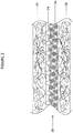
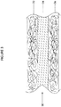
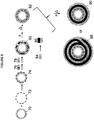
- FIGS. 1 and 2 Exemplary mono-component composite prosthetic devices (not forming part of the invention) are illustrated in FIGS. 1 and 2 .
- FIG. 1 illustrates a cross-sectional view of a wall of a composite prosthetic device 10, wherein the coverings on the inner (12) and outer (16) diameter surfaces of the device comprise the same dispersion-spun polymer (e.g ., PTFE).
- Layer 14 is a tie layer, comprising the same type of polymer (e.g ., PTFE), but layer 14 is initially incorporated into the structure in unsintered (tacky and moldable) form.
- FIG. 2 illustrates a cross-sectional view of a wall of a composite prosthetic device 20, which is similar but further incorporates a structural frame 24.
- layers 22, 26, and 28 comprise the same type of polymer (e.g ., PTFE) and the tie layer (26) is initially incorporated in unsintered form.
- the application of heating and pressure to the device precursor preferably causes the tie layer 26 to penetrate through interstices in structural frame 24, as well as into the pores of layer 22 and/or 28.
- the application of heating and pressure can cause tie layer 26 to bond the material comprising the inner diameter surface of the composite device to the material comprising the outer diameter surface of the device.
- the composite device precursor is preferably heated prior to use to provide layer 26 in sintered form in the final composite device ( e.g ., where the layer comprises PTFE).
- multi-component composite devices have at least two types of electrospun polymeric layers and can have any number of different types of polymeric materials therein (e.g ., at least 2, at least 3, or at least 4).
- Each polymer type within the multi-component composite devices as described herein can be represented in one layer or more than one layer.
- a composite device can have: one layer of a given first electrospun material and one layer of a given second electrospun material (not forming part of the invention); two or more layers of a given first electrospun material and one layer of a given second electrospun material (not forming part of the invention); or two or more layers of a given first electrospun material and two or more layers of a given second electrospun material.
- the multi-component composite devices provided herein in addition to comprising one or more dispersion-spun layers, comprise one or more additional layers, which can be prepared via dispersion-based electrospinning, melt-based electrospinning, and/or solution-based electrospinning.
- the one or more additional electrospun layers of the prosthetic device comprise an electrospun thermoplastic or thermoset polymer.
- a thermoplastic is understood to be any polymer that becomes moldable above a specific temperature and returns to a solid state upon cooling.
- a thermoset is understood to be a polymeric material that is initially moldable, but can cured (usually irreversibly) to give a solid ( e.g., by the application of heat or radiation).
- the thermoplastic or thermoset polymer is an elastomer.
- An elastomer is a polymer that can be repeatedly stretched and/or deformed without permanently deforming the shape thereof.
- polyurethanes PU
- silicones e.g ., polydimethylsiloxane
- Other polymers useful for this purpose include, but are not limited to, polyether block amide (PEBA, e.g., PEBAX®), polyamides, polyethylene (e.g., ultra-high molecular weight polyethylene, UHMWPE), polyesters, and copolymers, blends, and derivatives thereof.
- fluorinated polymers such as fluorinated ethylene propylene (FEP), polyvinylidene fluoride (PVDF), perfluoroalkoxy (PFA), a copolymer of tetrafluoroethylene, hexafluoropropylene and vinylidene fluoride (THV), poly(ethylene-co-tetrafluoroethylene) (ETFE), ethylene chlorotrifluoroethylene (ECTFE), PCTFE (polychlorotrifluoroethylene), and copolymers, blends, and derivatives thereof which can be electrospun can be used.
- FEP fluorinated ethylene propylene
- PVDF polyvinylidene fluoride
- PFA perfluoroalkoxy
- THV hexafluoropropylene and vinylidene fluoride
- ETFE poly(ethylene-co-tetrafluoroethylene)
- ECTFE ethylene chlorotrifluoroethylene
- PCTFE polychlorotri
- any thermoplastic or thermoset polymer that forms fibers upon electrospinning can be used in this regard as an additional polymeric component (in addition to the one or more dispersion-spun layers).
- the additional polymeric component is selected such that the electrospun mat produced therefrom retains some degree of porosity when it is combined with the other component(s) of the multi-component composite device and when the resulting device precursor is treated ( i.e., when it is exposed to elevated temperature and/or pressure) to provide a final composite device.
- one or more polymeric layers is a non-porous layer (which can be prepared in various ways as described herein, including, but not limited to, by electrospinning and/or by film formation).
- Certain multi-component devices described herein exhibit enhanced properties relative to commercially available devices and/or to mono-component devices described herein.
- Properties that may be enhanced in certain embodiments include, but are not limited to, robustness, flexibility, strength (e.g., radial strength and burst strength), crush/bend/kink resistance, and compression resistance, for example, as evaluated by testing methods including, but not limited to, air flow testing, torsion testing, tension/compression testing, abrasion resistance testing, burst strength testing, WEP testing, radial force expansion testing, kink resistant testing, 3-point bend testing, flex testing, crush resistance testing, recoil testing, and general physical evaluation.
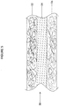
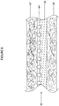
- FIGS. 3 and 4 Exemplary multi-component composite prosthetic devices (not forming part of the invention) are illustrated in FIGS. 3 and 4 .
- FIG. 3 illustrates a cross-sectional view of a wall of a composite prosthetic device 30, wherein the coverings on the inner (32) and outer (36) diameter surfaces of the device comprise the same electrospun polymer (e.g ., PTFE).
- Layer 34 is a tie layer, which comprises a different electrospun polymer than layers 32 and 36 (e.g., PU or PDMS). If layer 34 is a dispersion-spun material, layer 34 is initially incorporated into the structure in unsintered (tacky and moldable) form and must be sintered before the composite device is used.
- FIG. 4 illustrates a cross-sectional view of a wall of a composite prosthetic device 40, which is similar but further incorporates a structural frame 44.
- Layers 42 and 48 comprise the same electrospun polymer (e.g., PTFE) and the tie layer (46) comprises a different material.
- tie layer 46 is a dispersion-spun material
- layer 46 is initially incorporated into the structure in unsintered (tacky and moldable) form and must be sintered before the composite device is used. If tie layer 46 is a solution-spun or melt-spun material, no sintering is required prior to use. However, in all embodiments, the device precursor will be subjected to heat and/or pressure prior to use to promote adhesion between layers ( e.g ., via penetration of layer 46 into the pores of layer 42 and/or layer 48 ).
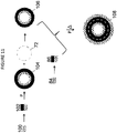
- FIG. 5 illustrates a cross-sectional view of a wall of a composite prosthetic device 50, wherein the coverings on the inner (52) and outer (56) diameter surfaces of the device comprise different polymers.
- Layer 54 is a tie layer, which may comprise the same polymer as layer 52 or 56 or may comprise a different material. If layer 54 is a dispersion-spun material, layer 54 is initially incorporated into the structure in unsintered (tacky and moldable) form and must be sintered before the composite device is used. If layer 34 is a solution-spun or melt-spun material, no sintering is required prior to use.
- FIG. 6 illustrates a cross-sectional view of a wall of a composite prosthetic device 60, which is similar but further incorporates a structural frame 64.
- Layers 62 and 68 comprise different polymers and the tie layer (66) can comprise the same polymer as layer 62 or 68 or may comprise a different material.
- tie layer 64 is a dispersion-spun material (e.g ., PTFE)
- layer 64 is initially incorporated into the structure in unsintered (tacky and moldable) form and must be sintered before the composite device is used.
- tie layer 64 is a solution-spun or melt-spun material, no sintering is required prior to use.
- the device precursor will be subjected to heat and/or pressure prior to use to promote adhesion between layers (e.g ., via penetration of layer 64 into the pores of layer 62 and/or layer 68).
- FIGS. 7A - 7F are schematic cross-sections of representative multi-component prosthetic devices according to the present disclosure, having greater than two layers.
- two polymeric components are present; the grey layers represent the dispersion-spun component (e.g., PTFE) and the black layers represent a different type of polymeric material (e.g., PU or PDMS).
- the dashed lines represent structural frames.
- FIGS. 7A - 7F a wide range of embodiments having different cross-sections can be provided according to the methods and materials disclosed herein.
- the structural frame can vary.
- Structural frames can take various forms including, but not limited to, stents, occlusion coils or frames, regenerative medicine scaffolds, structural reinforcements, pacing or monitoring leads, tissue anchors or tacks, biological stimulation devices, biomimetic implants, signal receivers or transmitters, orthopedic fixation devices or any other metallic, polymeric, ceramic or other therapeutic devices.
- Various stent types and stent constructions may be employed in the present disclosure, including, but not limited to, self-expanding stents and balloon expandable stents.
- the stents may be capable of radially contracting as well.
- Self-expanding stents include those that have a spring-like action which causes the stent to radially expand, or stents which expand due to the memory properties of the stent material for a particular configuration at a certain temperature.
- the structural frame is a metal structural frame, which can generally comprise any biocompatible metal.
- the metal structural frame can comprise stainless steel, platinum, gold, titanium, or a mixture thereof.
- the metal structural frame can comprise cobalt, chrome, or magnesium alloy.
- Nickel titanium alloy (“Nitinol") is one material which has the ability to perform well while both in spring-like mode, as well as in a memory mode based on temperature and thus may be useful in certain embodiments of the invention.
- the structural frame can comprise another type of material, such as a ceramic.
- the configuration of the structural frame may also be chosen from any suitable geometry.
- wire stents can be fastened into a continuous helical pattern, with or without a wave-like feature or zig-zag in the wire, to form a radially deformable stent.
- Individual rings or circular members can be linked together by struts, sutures, welding, or interlacing or locking to form a single tubular stent.
- Individual rings or circular members may have no link and thus may serve as individual units in the composite that is provided upon the combination of such a frame with one or more layers of polymeric material according to the invention. In such cases, multiple ring segments are embedded and held in place by the composite material to comprise a single tubular composite device.
- Tubular prosthetic devices useful in the present invention also include those formed by etching or cutting a pattern from a tube. Such devices are often referred to as "slotted" devices (e.g ., slotted stents). Furthermore, devices may be formed by etching a pattern into a material or mold and depositing device material in the pattern, such as by chemical vapor deposition or the like. As will be apparent based on the disclosure herein, there may be some limit on the configuration of a structural frame in order to achieve enhanced bonding between adjacent polymeric layers through the structural frame in certain embodiments.
- FIG. 7A-7F contain a structural frame; however, this is not necessary.
- a 100% electrospun polymer-based device is provided.
- a device is provided consisting only of a structural frame and electrospun polymeric layers.
- Composite devices comprising additional types of materials, however, are not intended to be excluded from the present disclosure. It is possible according to the present invention to incorporate various additional non-electrospun components into the mono-component prosthetic devices and multi-component prosthetic devices described herein.
- melt-processable polymers e.g., polyamides, polyurethanes, and the like (including, but not limited to, perfluoroalkoxy (PFA), fluorinated ethylene propylene (FEP), ethylene tetrafluoroethylene (ETFE), or tetrafluoroethylene hexafluoropropylene vinylidene fluoride (THV)) (which can provide a non-porous layer, e.g ., as a self-sealing thermoplastic or elastomeric film); woven or nonwoven fabrics of natural or man-made fibers; plastic or ceramic membranes; metal, ceramic, or plastic meshes; expanded PTFE (ePTFE) layers as discussed for example in U.S. Patent Application Publication Nos. 2011/0030885 and 2011/0031656 to Anneaux et al. .
- PFA perfluoroalkoxy
- FEP fluorinated ethylene propylene
- ETFE ethylene tetra
- the composite devices provided herein can comprise one or more bioactive agents.
- bioactive agents that can be utilized in connection with the devices of the present disclosure include, but are not limited to: antibiotics, antifungals, and antivirals (such as erythromycin, tetracycline, aminoglycosides, cephalosporins, quinolones, penicillins, sulfonamides, ketoconazole, miconazole, acyclovir, ganciclovir, azidothymidine, and interferons); vitamins; anticonvulsants (such as phenytoin and valproic acid); antidepressants (such as amitriptyline and trazodone); antiparkinsonism drugs; cardiovascular agents (such as calcium channel blockers, antiarhythmics, and beta blockers); antineoplastics (such as cisplatin and methotrexate), corticosteroids (such as dexamethasone, hydrocortisone,
- Bioactive agents can, in some embodiments, be as described in U.S. Application Ser. No. 13/272,412 to Ballard et al., filed October 13, 2011 .
- the amount of optional bioactive agent incorporated within the tubular composite devices can vary but is generally that amount sufficient to elicit a desired response in the patient in whom the device is to be implanted.
- a bioactive agent can be incorporated within only one layer or within more than one layer of the composite prosthetic device.
- the properties and characteristics of the final composite prosthetic devices of the present disclosure are a compilation of the properties of the espun polymer layers and any other optional material(s) contained within the composite device (e.g ., the optional one or more additional espun polymeric layers and the structural frame).
- the final composite devices of the present disclosure can, in certain embodiments, be prepared with controlled fiber sizes and the mechanical properties of the device can be tailored so as to improve such features as bond strength between components (e.g ., layers) of the device, elongation properties, and tensile strength. Moreover, different pore sizes of the layers can be targeted for different intended application.
- the individual layers exhibit little to no delamination, indicative of strong adhesion of layers to each other.
- the composite devices of the present disclosure can, in some embodiments, exhibit additional desirable characteristics of enhanced radial tensile strength, suture hole tearing resistance and enhanced axial tear resistance as compared with commercially available products.
- the ability to tailor such properties of the composite device of the present disclosure can have implications in designing prosthetic devices for particular applications.
- the properties of individual layers of the composite device can be modified to tailor the overall properties of the composite device for a given application.
- modifying the pore sizes and/or thicknesses of the polymeric layers can serve to enhance or inhibit cellular ingrowth or attachment.
- the device interior surface, or ID surface generally the fluid-, e.g., blood-contacting region
- the device exterior surface, or OD surface which is generally the tissue-contacting region
- a composite can comprise a layer having a large pore size on the exterior of the device to facilitate ingrowth and a layer having a smaller pore size on the interior of the device.
- the inverse is desired (i.e., a composite with minimal to no ingrowth on the exterior and enhanced ingrowth on the interior), which can be achieved by providing a composite comprising a layer having a small pore size on the exterior of the device and a layer having a larger pore size on the interior of the device.
- Electrospun mats useful according to the present disclosure can be prepared by drawing material by electrical charge from a polymer solution, from a polymer suspension/dispersion, or from a polymer melt.
- the fibers thus produced are typically collected in a random fashion to produce nonwoven materials.
- Various specific techniques are known for the production of electrospun fibers and electrospun materials (e.g ., mats and/or coverings).
- Dispersion-spun layers e.g ., PTFE and other fluorinated polymers discussed herein
- a dispersion comprising the desired polymeric particles is provided or prepared.
- the solids content of PTFE resins is preferably between 50% to about 80% by weight, and more preferably between about 55% and about 65% by weight.
- an exemplary commercially available PTFE dispersion Daikin D 210 PTFE, which comprises about 59-61 wt % PTFE solids (measured according to ASTM D 4441), 6.0-7.2% wt % surfactant, a pH at 25 °C of 8.5 to 10.5, a specific gravity of 1.50 to 1.53 and a Brookfield viscosity maximum of 35 cP.
- the properties of the PTFE e.g ., molecular weight, polydispersity index, particle size, particle size distribution
- the average particle size of the PTFE can be between about 0.05 ⁇ m and about 1 ⁇ m (for example, between about 0.1 ⁇ m and about 0.5 ⁇ m). In some embodiments, the average particle size is less than about 0.5 ⁇ m, less than about 0.4 ⁇ m, less than about 0.3 ⁇ m, or less than about 0.2 ⁇ m. For example, the average particle size in certain embodiments may be about 0.13 ⁇ m, about 0.16 ⁇ m, about 0.23 ⁇ m, or about 0.25 ⁇ m.
- the solvent can be any solvent suitable for creating a dispersion; suitable such solvents include, but are not limited to, aqueous solutions or alcohol solutions (e.g., methanol, ethanol, or isopropanol).
- a fiberizing polymer is typically added to the dispersion to facilitate fiber formation and is generally removed following the espinning process.
- the fiberizing polymer (or polymers) are typically selected such that they have a high solubility in the solvent of the dispersion (e.g., where the dispersion comprises water, any water-soluble polymer can be used, including, but not limited to, poly(ethylene oxide)).
- the amount of fiberizing polymer present in the dispersion can vary; for example, in certain embodiments, the dispersion comprises about 1% to about 10% by weight of a fiberizing polymer, based on the total weight of the dispersion.
- the weight ratio of fiberizing polymer to PTFE varies. For example, the amount of fiberizing polymer can be about 3.0% to about 5.5% that of the PTFE in the dispersion by weight.
- the amount of fiberizing polymer required according to the present invention may vary depending on the chemical makeup of the polymer.
- the viscosity of the dispersion is within a certain desirable range to allow for the formation of uniform and consistent fibers therefrom (e.g ., greater than about 50,000 mPa ⁇ s (cP) such as between about 50,000 mPa ⁇ s (cP) and about 300,000 mPa ⁇ s (cP) or between about 70,000 mPa ⁇ s (cP) and about 150,000 mPa ⁇ s (cP), as measured with a Brookfield Viscometer.
- the desired viscosity of the dispersion may vary depending on whether a free surfaced-based apparatus or an orifice (needle)-based apparatus (which requires a somewhat higher viscosity) is used.
- free surface electrospinning from a wire, a cylinder in a trough i.e., open bath
- a cylinder in a trough i.e., open bath
- spike, sharp edge, or similar geometry spinning electrode or the like is used.
- the ejection volume is dependent upon the viscosity of the dispersion, the conductivity of the dispersion, the surface tension of the dispersion, the distance from bath to target, and the voltage. These factors can also affect the thickness of the fabric and the fiber diameter.
- the charge source is preferably connected to the positive side of a precision DC power supply.
- the negative side of the power supply is preferably connected to the collection surface. Alternatively, the collection surface can be at ground. The polarity can be reversed but this is not preferred.
- Voltage is applied (e.g., typically from about 40,000 volts to about 120,000 volts (e.g., about 40,000 to about 80,000 volts) over a typical collection distance of about 100 to about 400 mm) to uniformly draw out the dispersion and attract it to a collection surface.
- the collection surface/target can be placed, for example, above the cylinder in the dispersion trough or the dispersion-coated wire and is typically moved in at least one direction such that the entire surface or the desired portion thereof becomes uniformly covered with fibers.
- orifice or needle spinning is used. This method is similar to that described above; however, the polymeric dispersion passes through one, two, or several orifices and forms espun fibers and fabrics in this way.
- the voltage on the power supply is increased to the desired voltage (usually from about 2,000 to about 20,000 volts) to uniformly draw out the dispersion and attract it to the collection surface.
- the collection surface is preferably placed perpendicular to the orifice and is rotated such that the entire surface is uniformly covered, with the fibers drawn towards the collection surface.
- electrospinning of PTFE may be based at least in part, on the process described in detail in U.S. Patent Appl. Publ. Nos. 2010/0193999 to Anneaux et al. and 2012/0114722 to Ballard et al ..
- Various parameters of the nanofiber production process can be modified to alter the properties of the resulting dispersion-spun (e.g., PTFE) material. For example, increasing the length of time generally increase the thickness of the espun material.
- the composite devices described herein can, in some embodiments be multi-component composite devices comprising at least one solution-spun or melt-spun component.
- Solution electrospinning is generally known in the art and, in some embodiments, can be conducted in a similar way as the dispersion-based electrospinning described above. Similar to dispersion-based electrospinning, an electrical charge is used to draw polymeric fibers from the solution, which are deposited, generally in a random fashion, on a collection surface.
- the solvent in which the polymer is dissolved and the parameters required to produce fibrous mats via electrospinning can vary, depending upon the nature of the polymer.
- any solution in which the polymer is dissolvable e.g ., tetrahydrofuran (THF), dimethylformamide (DMF), dimethylacetamide (DMAc), and combinations thereof
- THF tetrahydrofuran
- DMF dimethylformamide
- DMAc dimethylacetamide
- concentration of polymer in the solution can vary, but is generally relatively low (e.g., less than about 25% by weight, less than about 10% by weight, such as between about 1% and about 10% by weight).
- Parameters such as makeup of the solution (e.g ., the solvent, the composition and molecular weight of the polymer used, any additives, the concentration of the polymer in the solution, the solubility of the polymer in the solvent, etc.), the charge applied to the solution, the time period of electrospinning, etc. can impact the fibrous mat thus produced.
- Exemplary methods are described, for example, in U.S. Patent Nos. 1,975,504 ; 2,160,962 ; and 2,187,306, all to Formhals ; Demi et al., Polymer 43: 3303-3309 (2002 ); Greiner et al., Angew. Chem. Int. Ed. Engl.
- Melt electrospinning is similar to dispersion and solution electrospinning, but involves electrospinning fibers from melted polymer. Any polymer that can be placed in melt form has the potential to be electrospun by this method.
- a melted polymer sample to be spun can be prepared, for example, by heating from resistance heating, circulating fluids, air heating, or lasers. The temperature at which melt spinning is conducted will vary depending upon the melting point of the polymer or polymers used.
- the collection surface onto which the spun fibers are deposited can vary and can be dependent upon the type of electrospinning setup used.
- the collection surface is a sheet, the surface of which can be, e.g., any metal or polymeric material, with stainless steel being a particularly preferred material.
- the collection surface is a tubular prosthetic device (e.g ., in the form of a stent, stent-graft, or graft).
- the collection surface is a drum (i.e., a cylinder around which a collection sheet can be wrapped), which may be rotated during collection to generate a tubular structure.
- the tubular structure can be cut along the length of the tube to provide a sheet.
- the collection surface is a rod or tube ( i.e., a mandrel around which a collection sheet may be wrapped or on which the fibers may be collected directly) which may be rotated during the collection to generate a tubular structure.
- a tubular structure can, in certain embodiments, be directly used in its tubular form.
- Electrospun materials produced via solution and melt spinning are generally sufficient for manipulation immediately following production and generally do not require any further treatment to provide the desired fiber characteristics.
- the polymeric (e.g ., PTFE) mat/sheet, tube, or covered device is generally somewhat fragile and typically must be heated and/or sintered to provide a sufficiently strong and durable material for use as a component of a prosthetic device according to the invention. Heating generally serves to dry the material, volatilize and remove the fiberizing polymer, and/or to sinter the PTFE particles (e .g., by fusion of individual PTFE particles to produce a nonwoven, PTFE-based material).
- the sintering of the material generally results in the formation of a stronger, more durable material.
- the level of sintering can vary. During heating, the material can be monitored to evaluate the sintering level by various methods (e.g ., calorimetry and/or visual inspection).
- the material can be heated in place ( i.e., by placing the entire collection surface in an oven) or by removing the electrospun material from the collection surface prior to heating and placing the free electrospun material in an oven.
- the PTFE sheet or tube or PTFE-covered device can be heated and sintered alone, or in certain embodiments, it may be combined with other components of the composite device prior to heating.
- the heating and sintering can occur at any stage of the process of assembly of the composite prosthetic device. It is noted that the components of the composite structure must be considered to ensure that the other components can withstand the conditions required to sinter the PTFE (or other dispersion-spun polymer).
- the time and temperature at which the material is heated can vary.
- the temperature of the oven is between about 250 °C and about 800 °C, such as between about 300 °C and about 500 °C ( e.g ., between about 350 °C and about 485 °C).
- the PTFE (or other dispersion-spun polymeric material) is generally exposed for a period of time such that any remaining water is evaporated and the fiberizing polymer undergoes decomposition and subsequent elimination of the residual material. It is noted that, in some embodiments, PTFE can be sintered in combination with one or more additional materials.
- the time for which a dispersion-espun material is heated to sinter the material may depend, in part, on the temperature of the oven.
- the material is sintered for a period of about an hour or less, about 30 minutes or less, about 20 minutes or less, about 15 minutes or less, or about 10 minutes or less.
- the sintering is conducted for a time of between about 2 and about 30 minutes, preferably between about 5 and about 20 minutes. It is noted that more time may be required for sintering at lower temperature and less time may be required for sintering at a higher temperature.
- the time required for drying and sintering can also depend on the thickness of the material, with thicker materials requiring more time to dry and/or sinter.
- the drying, volatilizing, and sintering of a dispersion-spun material can occur simultaneously or in a series of steps. While not intended to be limited by any theory, it is believed that some drying (i.e., removal of the solvent) may occur upon completion of electrospinning. It is further believed that some small degree of fiber rearrangement may occur at this point. Then when the material is heated, preferably, the majority of the solvent and the fiberizing polymer (e.g ., greater than about 80%, preferably greater than about 90% or 95%, and most preferably greater than about 98 or 99%) is removed from the PTFE material. It is understood that espun fabric generally undergoes shrinkage upon heating/sintering. While not limited to any theory, the shrinkage is believed to occur in two steps: the initial drying and fiber rearrangement following the electrospinning process, and the removal of solvent and fiberizing polymer by heating/sintering.
- the method comprises assembling the layers to be incorporated within the composite and applying heat and pressure to provide a composite prosthetic device.
- the means by which the final structure is assembled can vary.
- an electrospun polymer sheet or tube is produced independently and then combined with the additional layers to form a composite structure.
- the polymer sheet can be a single polymer sheet (e.g., a sintered PTFE mat, a PU mat, a PDMS mat, etc.).
- a multi-layered espun polymer sheet (“combination sheet") can be provided.
- an espun PTFE mat is produced and sintered. Another polymer is then directly electrospun onto the sintered espun PTFE mat, producing a two-layered mat of electrospun polymer.
- one espun PTFE mat in the preparation of mono-component composites, one espun PTFE mat can be prepared and another espun PTFE layer can be deposited directly thereon.
- one espun PTFE mat in the preparation of multi-component composites, one espun PTFE mat can be prepared and another type of polymer can be directly electrospun thereon (e.g., PU or PDMS).
- Such combination mats can be provided with varying combinations of espun polymeric layers and with varying numbers of such layers.
- a mat (a single electrospun mat or a combination sheet) can, in certain embodiments, be "laminated” onto another material (e.g., onto a polymeric tube, a structural frame, or onto a covering thereon), e.g ., by wrapping the mat around the other material.
- This process generally involves layering or wrapping the espun mat or mats directly onto or around the material to be covered, giving a prosthetic composite device precursor, and applying heat and pressure thereto to provide a prosthetic composite device.
- the layering or wrapping can be performed such that the sheet/layer is wrapped one time around a construct or multiple times around the construct ( e.g., two times, three times, four times, or more times).
- the number of wrappings of each sheet can affect the thickness of that layer of the final composite. For example, a device wherein a given electrospun mat is wrapped twice around a construct will give a thicker layer of that electrospun material in the final device than in a device wherein that electrospun mat is wrapped only once around the construct. The overall wall thickness of a device having a greater number of wrappings will thus be thicker as well. Where a combination sheet is used, the number of wraps will alter the number of layers of the two (or more) components comprising the combination sheet.
- FIGS. 7A and 7B and FIGS. 7D and 7E are comparable to one another except that the number of wrappings of the outer two components are different, as will be described in greater detail below.
- a polymer is directly spun onto another component of the composite prosthetic device.
- electrospinning can be conducted such that a polymer covering is directly spun onto a construct (e.g ., a polymeric tube or a structural frame, such as a stent).
- two or more methods can be combined (e.g., a covering can be applied to a structural frame by directly electrospinning the covering thereon and the resulting device can be subsequently wrapped with a second covering and treated as described herein or a covering can be applied to a structural frame by wrapping and a second covering can be applied to the covered structural frame by directly electrospinning the second covering thereon).
- the composite prosthetic devices of the present disclosure generally incorporate at least one tie layer, which can be incorporated within the device precursor as an unsintered dispersion-spun layer (which is subsequently sintered prior to use of the device) or which can be a solution-spun or melt-spun layer (which does not require sintering prior to use of the device).
- the tie layer can be applied using any of the methods described herein.
- the tie layer can serve as a "glue" to bind to another layer and preferably can be used to bind multiple layers together.
- the tie layer can penetrate the open spaces in the structural frame and bond to the material on the other side of the structural frame (e.g., where the tie layer is provided on the outer surface of the structural frame, it can penetrate the frame and bond to the material comprising the inner diameter surface of the structural frame which may, in some embodiments, be a porous electrospun polymeric layer).
- the tie layer may serve to bond and/or connect the material on the inner diameter surface of the composite device to the material on the outer diameter surface of the composite device.
- a significant advantage to the presence of such a tie layer is that it can serve to create a better bond and/or seal between various layers of the composite device following the application of heat and/or pressure to the composite device precursor.
- This bonding can be characterized, for example, by an enhanced peel strength between certain layers.
- the preparation of composite devices of the present disclosure involves the incorporation of an unsintered PTFE tie layer.
- the stage at which any unsintered PTFE present in the composite device is sintered must be such that no material is present that will be negatively affected by the temperatures required for the sintering of the PTFE.
- any unsintered PTFE layer(s) applied to the device should be sintered prior to the application of the PU to avoid destroying the porous PU layer(s) during the sintering of the PTFE layer(s).
- an unsintered PTFE layer is generally useful as a tie layer in composites only where the adjacent layers of the device precursor comprise PTFE or another, similar polymer (and not in composites wherein a PU or other, similar polymer is adjacent to the unsintered PTFE).
- the preparation of composite devices of the present disclosure involves the incorporation of a solution-spun tie layer (e.g., including, but not limited to, PU or PDMS).
- a solution-spun tie layer e.g., including, but not limited to, PU or PDMS.
- Such tie layers which do not require sintering prior to use of the composite device, can be advantageous as the processing of the device does not require the structural frame, where present, to be exposed to the high temperatures required for sintering (as required for, e.g., a PTFE tie layer). In certain embodiment, avoidance of such high temperatures can serve to keep the mechanical properties and integrity of the device more intact.
- the amounts and relative amounts of material in the layers of the composite prosthetic devices described herein can vary. It is noted that, with regard to the tie layer, in embodiments wherein a structural frame is present, the wire/strut diameter, spacing between the wires/struts struts, and/or the processing conditions may impact the amount of material required to ensure sufficient bonding of the tie layer to other layers and/or to the structural frame. For example, large wire or strut diameters or thicknesses may need more of the tie-layer espun polymer material as compared to smaller wire or strut diameters (which can be provided, e.g., by using a thicker espun sheet and/or by wrapping a sheet more times around the device).
- a structural frame with minimal spacing between the wire or strut lattice may not perform as well due to minimal inner diameter and outer diameter contact, resulting in a poorly secured and embedded structural frame.
- even structural frames with minimal spacing between the wire or strut lattice can perform well if enough tie layer espun polymer material is used and enough heat and/or pressure is applied to ensure that the tie layer espun polymer can penetrate the open spaces in the lattice.
- tie layer material there is a certain amount of tie layer material that must be applied to the structural frame, a certain amount of processing (e.g., temperature and/or pressure) that must be applied to the structural frame, there must be a sufficient amount of open space in the frame to ensure that the frame is not “floating" within the composite and is adequately affixed onto or within the other layers of the composite, and the tie layer material must have sufficient properties (e.g., flowability and/or tackiness) to enable it to effectively penetrate the open spaces of the structural frame.
- processing e.g., temperature and/or pressure
- the device precursor is subjected to heat and pressure.
- the application of heat and pressure to the precursors as intended herein generally results in some degree of fusion and/or merging of the various layers of the composite device precursor (e.g., via the tie layer penetrating through the open spaces in a structural frame and/or penetrating the pores of at least one of the adjacent layers).
- the application of heat and pressure can also ensure that the inner diameter surface of a composite device is bonded to the outer diameter surface of the composite device.
- the application of heat and pressure can advantageously seal the frame within the composite device so that there is no delamination and/or so that the frame is completely covered by one or more polymeric layers.
- application of heat and pressure can result in a decrease in effective pore size of the individual layers and/or composite as a whole and/or can result in a decrease in individual layer thickness and/or wall thickness of the composite as a whole.
- the amount of heat and the method by which the heat is applied to the device precursor can also vary.
- heat can be applied by heating the device precursor in various types of chambers (e.g., heating vessel or clamshell) or by heating the device in an oven.
- heat applied at this stage is typically significantly lower than the heat required to sinter the dispersion-spun component or components (e.g., PTFE).
- the temperature applied can vary depending on the makeup of the device precursor, as discussed in greater detail below.
- the one or more dispersion-spun components are present in sintered form when the heat and/or pressure is applied to the multi-component device precursor.
- the heating step can include sintering.
- heat and pressure is applied to the device precursor to cause the unsintered dispersion-spun tie layer to penetrate the pores of one or both of the adjacent layers (and, optionally, to penetrate through the open pores of the structural frame, where present) and the heat applied can advantageously be sufficient to sinter the one or more unsintered dispersion-spun component.
- the heat and pressure required to ensure penetration of one or more layers as described herein may be insufficient to sinter the unsintered dispersion-spun component
- pressure can be applied by using a flat press, constricting wrap, and/or mechanical nip roller.
- physical pressure is applied to the device precursor by wrapping the construct with a constricting wrap and applying pressure, either directly or indirectly.
- the constricting wrap is maintained on the covered construct and the entire device precursor, including the constricting wrap, is heated; subsequently, the constriction wrap is removed to provide a compressed composite device.
- pressure can be applied to the device precursor in a pressure vessel. Pressure vessels of varying design and size can be useful according to the methods provided herein.
- the pressure vessel can be a heated pressure vessel, allowing heat and pressure to be applied to a device precursor simultaneously.
- the pressure rating of the vessel can vary, so long as sufficient pressure may be applied to the device precursor to allow the tie layer to penetrate through the open spaces in a structural frame and/or to penetrate the pores of at least one of the adjacent layers.
- Exemplary pressure vessels include, but are not limited to, Non-Stirred Pressure Vessels from Parr Instrument Company (Moline, IL). Other means for the application of pressure are intended to be encompassed herein as well. Due to the porosity of the composite device precursors described herein, it may be necessary, in certain embodiments, to enclose the device precursor in a non-porous material prior to introducing it into the chamber.
- non-porous material must be based on the conditions to which the device precursor will be subjected in the chamber.
- the non-porous material must be capable of withstanding the elevated pressure and/or temperature conditions within the chamber without negatively impacting the enclosed composite device precursor and/or device.
- both heat and pressure are applied to the device precursor, it is not necessary for the heat and pressure to be applied simultaneously, but in some embodiments, they may be applied simultaneously (e.g ., in a heated pressure vessel). Further, it is noted that the application of pressure and heat may be conducted at various stages of construction of the composite prosthetic device. In some embodiments, pressure is applied, followed by the application of pressure and heat. In some embodiments, the entire device is assembled and pressure and heat are applied to provide the final device. In other embodiments, the application of pressure and heat can be conducted at one or more stages during the assembly process.
- the amount of heat and pressure advantageously applied to prepare the composite device precursor can depend on the makeup of the layers of the device.
- the applied pressure is between about 34.47 bar (500 PSI) and about 103.4214 bar (1500 PSI) and the temperature is at least about 50 °C or at least about 100 °C ( e.g ., between about 75 °C and about 400 °C or between about 100 °C and about 300 °C).
- the time and temperature are related, i.e., increasing the temperature at which the device precursor is treated may allow for a decrease in the pressure applied (particularly where the temperature and pressure are applied simultaneously).
- the temperature can also depend on the makeup of the composite device precursor.
- the composite device is preferably heated at a temperature sufficient to sinter the unsintered PTFE (e.g., about 385 °C).
- a temperature sufficient to sinter the unsintered PTFE e.g., about 385 °C.
- the temperature applied is advantageously significant lower (e.g., between about 100 °C and about 200 °C).
- the time at which heat and pressure is applied can also vary; generally, the device precursor must be exposed to the heat and pressure for a sufficient period of time to ensure that the tie layer can penetrate through the open spaces in a structural frame and/or can penetrate the pores of at least one of the adjacent polymeric layers (e.g., at least about 3 minutes, at least about 5 minutes, or at least about 7 minutes, including between about 3 and about 20 minutes, between about 5 and about 15 minutes, between about 5 and about 10 minutes, and between about 5 and about 7 minutes). Although such times are noted to be useful, it is understood that in some embodiments, the composite device can be heated for lesser or more amounts of time. Generally, the heat and pressure should be applied for a period of time sufficient for bonding.
- the time is also related to the heat and pressure, such that in some embodiments, treatment of the device precursor at a higher temperature and pressure may require less time than treating that same device precursor at a lower temperature and pressure. It is understood, however, that there is some minimum temperature and pressure that will be required to ensure the device exhibits penetration of the tie layer through the open spaces in a structural frame and/or to ensure penetration of the tie layers into the pores of at least one of the adjacent layers (e.g., in certain embodiments, ensuring bonding between the inner diameter surface of the composite device and the outer diameter surface of the device).
- the melt flow characteristics of a tie layer polymer may affect the choice of heat and pressure to be applied. For example, a tie layer comprising a polymer with a higher melt flow rate may require less heat and pressure to ensure that the tie layer effectively penetrate the pores of at least one of the adjacent layers, whereas a polymer with a tie layer comprising a lower melt flow rate may require more.
- the structural frame may impact the amount of heat and pressure to be applied to the device precursor. In some embodiments, greater heat and pressure may be required to ensure that the tie layer can penetrate through the open spaces in the frame.
- a composite device comprising a structural frame with a thick wire or strut may not be prepared in the same way as a device comprising a structural frame with a thin wire or strut.
- a frame with a thick wire or strut or a frame with narrow spaced wires or struts may require more electrospun polymeric material (e.g., a thicker covering), may require the use of an electrospun polymeric material having a greater ability to flow and penetrate the open spaces (e.g., a polymer having a higher melt flow rate), and/or may require greater heating and pressure applied thereto to ensure that the covering can penetrate the open spaces within the frame.
- the spacing between wires or struts of a structural frame may similarly affect the materials and parameters of the methods used to form a composite device comprising the frame.
- the structural frame has widely-spaced wires or struts (e.g., with amplitudes spaced relatively far apart and/or having fewer wires or struts)
- less heat and pressure may be required than for a comparable embodiment wherein the structural frame closely spaced wires or struts (e.g., with amplitudes closer together and/or having more wires or struts).
- thermoset polymer is employed (e.g., as a tie layer) in the composite prosthetic device precursor
- the thermoset polymer is advantageously heat-cured during the application of heat and pressure as described above. In some embodiments, this curing requires a higher temperature than those noted above, e.g., at least about 200 °C.
- a thermoset polymer is employed that is cured through radiation.
- it is not cured until during or after the heat and pressure treatment described above, such that it can flow into the pores of one or more adjacent layers in uncured form and subsequently be cured to provide a composite prosthetic device.
- tailoring refers to the ability to produce and use various materials with various properties.
- tailoring relates to the process conditions used in espinning; by varying the parameters of the method, polymeric sheets, tubes, or covered constructs having different physical properties can be obtained. For example, where a thicker polymeric mat/tube (or a thicker covering directly spun onto a construct) is desired, the espinning process can be conducted for a longer period of time to deposit more material. As another example, where a polymeric mat with smaller pore size is desired, a thicker mat can be prepared, which typically results in a decreased pore size.
- a smaller pore size can be obtained by decreasing the targeted fiber diameter.
- tailoring relates to the method of assembly of the composite device. For example, where a thicker polymeric layer within the device is desired, a given polymeric mat can be wrapped around the composite device precursor a greater number of times. Thus, tailoring the properties of a given layer of the composite device can be done in various ways, relating to the production of the espun layer and/or the application of the espun layer to the composite device. In further embodiments, where a device having one or more impermeable portions is desired, a thermoplastic polymeric film may be incorporated within the composite device.
- bioactive agents can be included in one or more of the layers of the device.
- Such optional bioactive agents can be incorporated within composite devices in a variety of ways.
- the one or more bioactive agents can be directly incorporated into the fibrous mats by including them in a dispersion, solution, or melt that is espun, or the one or more bioactive agents can be incorporated into a layer or into the composite device after the fibers are prepared, e.g., by applying the bioactive agents, e.g., in solution form, onto/into the layer or device.
- Certain exemplary means for the incorporation of bioactive agents are described in U.S. Application Ser. No. 13/272,412 to Ballard et al., filed October 13, 2011 .
- the referenced application is directed to the incorporation of antimicrobial agents, the antimicrobial agent could be replaced with the desired bioactive agent in the methods described herein.
- the properties and characteristics of the final composite prosthetic device produced may be impacted by the application of heat and pressure.
- the degree of heating i.e., time and temperature
- the amount of pressure applied and the method by which the pressure is applied may affect the overall quality of the final composite. If there is not enough heat and pressure, poor bonding and delamination may occur, resulting in weak adhesion of the layers to each other. Additionally, without sufficient heat and pressure, some portion of the structural frame may be exposed (i.e., uncovered), which in certain embodiments is not desirable. Further, without sufficient heat and pressure, the structural frame may move within the composite device, which is typically undesirable.
- heat and pressure can have varying impacts on the composite prosthetic device. Generally, the application of heat and pressure results in some degree of fusion and/or merging of the various layers of the composite device.
- heat and pressure can serve to aid in the penetration of the material comprising the tie layer of the composite into the pores of one or both of the layers adjacent thereto. Where a structural frame is present, the heat and pressure can, in some embodiments, cause the tie layer to penetrate the open spaces in the frame.
- the heat and pressure is thus preferably such that the tie layer of the prosthetic device precursor is moldable or flows to some extent into the pores of adjacent layers (and, optionally, through the open spaces of a structural frame, where present).
- the tie layer of the composite device precursor comprises an unsintered, dispersion-spun fibrous mat (e.g., PTFE)
- additional heating is generally required to sinter the material.
- the tie layer of the composite device precursor comprises a solution-spun material (e.g., PU or PDMS)
- PU or PDMS solution-spun material
- a tie layer as described above for example, in the form of an unsintered dispersion electrospun fibrous layer (e.g., PTFE) or a solution-spun fibrous layer (e.g., PU or PDMS)) between two or more other layers (and optionally through the open spaces of a structural frame) can provide significantly increased bonding between those layers following the application of heat and pressure (and, optionally, sintering, in the case of PTFE).
- PTFE unsintered dispersion electrospun fibrous layer
- PU or PDMS solution-spun fibrous layer
- a tie layer can, in certain embodiments, bond through a structural frame to a porous electrospun polymeric layer comprising the internal diameter surface covering of the composite device.
- the tie layer can also, in some embodiments, bond to an additional porous electrospun layer adjacent thereto, e.g., by penetrating the pores thereof.
- the composite devices described herein can, in certain embodiments, exhibit greater peel strengths between adjacent layers, which can result in enhanced performance of the resulting composite.
- the application of heat and pressure to the composite prosthetic device precursor can result in a decrease in effective pore size of the walls of the device and/or can result in a decrease in the overall wall thickness of the device.
- the heat and pressure applied to the device precursor may impact the pore size and/or the thickness of one or more individual espun layers.
- An increase in pressure and/or temperature may be associated with a decrease in pore size and/or a decrease in the layer thickness.
- a PU or other meltable polymer would be expected to flow to some extent upon the application of heat and pressure, thus reducing the effective pore size of the PU layer relative to the PU layer prior to the application of heat and pressure.
- polymers electrospun from solution e.g., PU and PDMS
- the effective pore sizes of certain layers can thus be controlled to some extent by both electrospinning conditions used to prepare the electrospun layer and by the treatment to which the layers are subjected within the composite device.
- the effective pore size of the composite as a whole may not be reflective of the combination of effective pore sizes of the individual layers. Consequently, in some embodiments, the methods described herein provide devices incorporating thermoplastic polymers or thermoset polymers which exhibit some overall degree of porosity.
- varying the materials as well as the temperature and pressure at which the device is processed can provide devices exhibiting varying degrees of porosity, as evidenced by the ability to obtain effective pore size measurements of the device as a whole.
- the materials and methods can be selected so as to ensure that porosity is maintained.
- the retention of some degree of porosity in an electrospun mat can be impacted, for example, by the melting point of the polymer and/or by the melt flow viscosity.
- Various parameters can affect these parameters including, but not limited to, the molecular weight of the polymer and the degree of branching within the polymer backbone. Consequently, a wide range of polymers can be tailored and optimized for use according to the present invention by varying these and other parameters and/or by blending two or more different types of polymers.
- Exemplary preparation methods for certain composite prosthetic devices according to the present disclosure are further described and exemplified below. It is noted that these categories are not intended to be exclusive.
- two composite devices can, in certain embodiments, be separately prepared and combined. Accordingly, in some embodiments, two composites devices or components thereof can be separately prepared; subsequently, one composite can be wrapped around or inserted into another composite, and pressure and heat can be applied the entire combined composite structure to form a single composite prosthetic device.
- a polymer-based composite can be combined with a composite prosthetic device including a structural frame, e.g., by separately preparing the two device types and wrapping the polymer-based composite around the composite prosthetic device including a structural frame or inserting it into the inner diameter of the composite prosthetic device including a structural frame. Again, heat and pressure can then be applied to the entire structure to form a single composite prosthetic device. All combinations, as well as singular composite prosthetic devices as described herein are intended to be encompassed by the present disclosure.
- FIGS. 7-11 Certain exemplary composite devices of the present disclosure and representative methods for preparing each are provided in FIGS. 7-11 . These are only exemplary constructions and exemplary means for preparing such constructions. These schematics provided in the figures and described herein are presented only to give exemplary means by which the principles described herein can be applied to certain specific components (to generate the representative constructs illustrated in FIGS. 7A-7F ).
- FIG. 8 illustrates an exemplary preparation of the composite devices illustrated in FIGS. 7A and 7B (not forming part of the invention).
- an electrospun PTFE mat is prepared, sintered, and wrapped, e.g. , around a hypotube, to form a tubular structure 70.
- a structural frame 72 is applied around structure 70, giving a frame-containing structure 74.
- An unsintered mat of espun PTFE 76 is wrapped around the structural frame ( e.g., to serve as a tie layer) and a sintered espun PTFE mat 78 is wrapped around unsintered mat 76.
- Pressure and heat are applied to the resulting composite device precursor 80, sufficient to sinter the unsintered PTFE of tie layer 76, giving a mono-component device 82.
- an electrospun PTFE sheet 84 is prepared and sintered; a combination PU/PTFE sheet 86 is prepared by electrospinning PU directly onto sheet 84.
- the combination sheet is wrapped around mono-component construct 82, with the PU layer laid directly against the outer surface of construct 82.
- the entire device precursor is then simultaneously subjected to pressure and heat.
- the multi-component cross-section on the left (88) depicts the result of the above process wherein the combination sheet is wrapped twice around the construct and the multi-component cross-section on the right (90) depicts the result of the above process wherein the combination sheet is wrapped once around the construct.
- the present disclosure provides a method (not forming part of the invention) for producing a composite prosthetic device comprising: applying a structural frame over a porous electrospun poly(tetrafluoroethylene) tubular structure; wrapping an unsintered poly(tetrafluoroethylene) mat around the structural frame (one or more times); wrapping a sintered poly(tetrafluoroethylene) mat around the unsintered poly(tetrafluoroethylene) mat (one or more times); and heating the resulting construct to sinter the unsintered poly(tetrafluoroethylene).
- such a method can further comprise preparing a combination electrospun mat by electrospinning a different polymer onto a sintered poly(tetrafluoroethylene) mat; wrapping the combination electrospun mat around the construct (one or more times, with the different polymer surface of the mat in contact with the construct) to give a precursor; and applying heat and pressure to provide a composite prosthetic device.
- FIG. 9 illustrates an exemplary preparation of the composite device illustrated in FIG. 7C (not forming part of the invention).
- the method is initially identical to that described above with regard to the method illustrated in FIG. 8 .
- a single PU sheet 92 is independently prepared and wrapped around mono-component construct 82, rather than the combination sheet depicted in FIG. 8 .
- the entire device precursor is then subjected to pressure and heat to give a multi-component composite device 94.
- the present disclosure provides a method (not forming part of the invention) for producing a composite prosthetic device comprising: applying a structural frame over a porous electrospun poly(tetrafluoroethylene) tubular structure; wrapping an unsintered poly(tetrafluoroethylene) mat around the structural frame (one or more times); wrapping a sintered poly(tetrafluoroethylene) mat around the unsintered poly(tetrafluoroethylene) mat (one or more times); heating the resulting construct to sinter the unsintered poly(tetrafluoroethylene); wrapping an electrospun mat comprising a different polymer around the construct (one or more times) to give a precursor; and applying heat and pressure to provide a composite prosthetic device.
- FIG. 10 illustrates an exemplary preparation of the composite device illustrated in FIG. 7D and 7E (not forming part of the invention).
- a frame-containing structure 74 is prepared by combining a sintered PTFE tube and a structural frame.
- an electrospun PTFE sheet 84 is prepared and sintered;
- a combination PU/PTFE sheet 86 is prepared by electrospinning PU directly onto sheet 84.
- the combination sheet is wrapped around structure 74, with the PU layer laid directly against the outer surface ( i.e., the structural frame) of structure 74.
- the entire device precursor is then subjected to pressure and heat simultaneously.
- the cross-section on the left (96) depicts the result of the above process wherein the combination sheet is wrapped once around the construct and the multi-component cross-section on the right (98) depicts the result of the above process wherein the combination sheet is wrapped twice around the construct.
- the present disclosure provides a method (not forming part of the invention) for producing a composite prosthetic device comprising: applying a structural frame over a porous electrospun poly(tetrafluoroethylene) tubular structure; preparing a combination electrospun mat by electrospinning a different polymer onto a sintered poly(tetrafluoroethylene) mat; wrapping the combination electrospun mat around the construct (one or more times, with the different polymer mat surface in contact with the construct) to give a precursor; and applying heat and pressure to provide a composite prosthetic device.
- FIG. 11 illustrates an exemplary preparation of the composite device illustrated in FIG. 7F .
- An electrospun PTFE sheet 100 is prepared and sintered; a combination PU/PTFE sheet 102 is prepared by electrospinning PU directly onto sheet 100.
- Combination sheet 102 is wrapped to form a tubular structure (with the PTFE on the interior of the structure), which is then compressed to give structure 104.
- a structural frame 72 is applied around the compressed, tubular material to give frame-containing structure 106.
- an additional espun PTFE sheet 84 is prepared and sintered and a second combination PU/PTFE sheet 86 is prepared by electrospinning PU directly onto sheet 84.
- Sheet 86 is then wrapped around structure 106, with the PU layer laid directly against the outer surface (i.e., the structural frame) of structure 106.
- the resulting device precursor is subjected to pressure and heat to give multi-component prosthetic device 108.
- the present disclosure provides a method for producing a composite prosthetic device comprising: preparing a combination electrospun mat by electrospinning a different polymer onto a sintered poly(tetrafluoroethylene) mat; forming the combination electrospun mat into a tubular structure having two or more alternating layers, wherein the poly(tetrafluoroethylene) surface of the mat is on the inner surface of the tubular structure and the different polymer surface of the mat is on the outer surface of the tubular structure; applying a structural frame over the outer surface of the tubular structure; preparing a second combination electrospun mat by electrospinning a different polymer onto a sintered poly(tetrafluoroethylene) mat; wrapping the combination electrospun mat around the construct (one or more times, with the different polymer mat surface in contact with the construct) to give a precursor; and applying heat and pressure to provide a composite prosthetic device.
- Example 1 Espun PTFE/ espun PTFE /espun PTFE (not forming part of the invention)
- An espinning dispersion based on a mixture of 5.2% (PEO/PTFE) 300,000 amu polyethylene oxide and Daikin DX-9030, 60% PTFE dispersion in water is prepared, allowed to homogenize, and turned and filtered to achieve a smooth consistency.
- a 0.002" thick stainless steel foil sheet (15.5" x 17.5") is mounted on a conductive fabric. The stainless foil is passed into the espinning chamber where PTFE fibers are to be deposited.
- the dispersion is espun using a total potential of 80 kV to facilitate formation of PTFE fibers, which collect in random formation on the stainless steel foil.
- the stainless steel foil containing the PTFE membrane is removed from the fabric and sintered at 385 °C until fully sintered (e.g., about 5 minutes).
- the 0.0008" sintered espun PTFE sheet, removed from the stainless foil, is wrapped twice around a 0.50" exterior diameter (OD) stainless steel hypotube.
- the electrospinning process is repeated to give a second espun PTFE sheet.
- the espun PTFE sheet, a 0.0018" unsintered espun PTFE sheet, is removed from the stainless foil and wrapped twice around the sintered espun PTFE layer.
- the electrospinning process is repeated to give a third espun PTFE sheet, which is then sintered.
- the third espun PTFE sheet a 0.0018" sintered espun PTFE sheet, is removed from the stainless foil after sintering and wrapped twice around the unsintered espun PTFE layer to create a tube assembly consisting of sintered espun PTFE/unsintered espun PTFE/sintered espun PTFE.
- the entire construction is then compressed together and heated/sintered at 385 °C for about 5-15 minutes (until fully bonded, as evidenced by lack of delamination), followed by water quenching as a means to cool down the sample.
- the composite device is then removed from the hypotube and tested for specified properties. The thickness of the construction was found to be approximately 0.005" and the effective pore size was found to be approximately 1.5 ⁇ m.
- Example 2 Espun PTFE / stent / espun PTFE / espun PTFE (not forming part of the invention)
- Example 2 is made similarly to Example 1 with the addition of a wire stent frame as an additional layer of the composite.
- An espinning dispersion based on a mixture of 5.2% (PEO/PTFE) 300,000 amu polyethylene oxide and Daikin DX-9030, 60% PTFE dispersion in water is prepared, allowed to homogenize, and turned and filtered to achieve a smooth consistency.
- a 0.002" thick stainless steel foil sheet (15.5" x 17.5") is mounted on a conductive fabric. The stainless foil is passed into the espinning chamber where PTFE fibers are to be deposited.
- the dispersion is espun using a total potential of 80 kV to facilitate formation of PTFE fibers, which collect in random formation on the stainless steel foil.
- the stainless steel foil containing the PTFE membrane is removed from the fabric and sintered at 385 °C for 5 minutes.
- the 0.0008" sintered espun PTFE sheet, removed from the stainless foil, is wrapped twice around a 0.50" exterior diameter (OD) stainless steel hypotube.
- a metal stent frame is then applied over this 0.0008" sintered espun PTFE sheet.
- the electrospinning process is repeated to give a second espun PTFE sheet.
- the espun PTFE sheet, a 0.0018" unsintered espun PTFE sheet, is removed from the stainless foil and wrapped twice around the stent.
- the electrospinning process is repeated to give a third espun PTFE sheet, which is then sintered.
- the third espun PTFE sheet a 0.0018" sintered espun PTFE sheet, is removed from the stainless foil after sintering and wrapped twice around the unsintered espun PTFE layer to create a tube assembly consisting of sintered espun PTFE/stent/unsintered espun PTFE/sintered espun PTFE.
- the entire construction is then compressed together and heated/sintered at 385 °C for 15 minutes, followed by water quenching as a means to cool down the sample.
- the composite device is then removed from the hypotube and tested for specified properties. The thickness of such a construction is found to approximately 0.005" and the effective pore size was found to be approximately 1.5 ⁇ m.
- Example 3 Espun PTFE / espun PVDF / espun PTFE (not forming part of the invention)
- a 0.0015" thick stainless foil sheet 17" X 18.5" is wrapped around a rotating drum.
- the drum assembly is placed into a rotating chuck such that it is positioned to allow espinning along the entire length of the turning drum assembly.
- An espinning solution based on a mixture of 25% Atofina Kynar 740 polyvinylidene fluoride (PVDF) and a 50/50 (by volume) mixture of acetone and dimethyl formamide is allowed to dissolve and mix using a heated stir plate set to 75 °C at 500 rpm for 1 hour.
- a voltage of 15.0 kV is employed to facilitate formation of PVDF fibers, which collect in random formation on the stainless foil sheet.
- the stainless soil sheet containing the PVDF mat is removed from the drum and dried for 1 hour at room temperature.
- a 0.001" sintered espun PTFE sheet, removed from the stainless foil, is wrapped twice around a 0.50" exterior diameter (OD) stainless steel hypotube.
- the 0.001" espun PVDF sheet, removed from the stainless foil is wrapped twice around the sintered espun PTFE layer.
- a 0.001" sintered espun PTFE sheet is wrapped twice around the espun PVDF layer to create a tube assembly consisting of sintered espun PTFE/espun PVDF/sintered espun PTFE.
- the entire construction is then compressed together prior to heating/sintering at 370°C for 15 minutes followed by water quenching as a means to cool down the sample.
- the composite is then removed from the hypotube and tested for specified properties.
- Example 4 Espun PTFE / stent / espun PVDF / espun PTFE (not forming part of the invention)
- Example 4 is made similarly to Example 3 with the addition of a wire stent frame as another support layer.
- An espinning dispersion based on a mixture of 5.2% (PEO/PTFE) 300,000 amu polyethylene oxide and Daikin DX-9030, 60% PTFE dispersion in water is prepared, allowed to homogenize, and turned and filtered to achieve a smooth consistency.
- a 0.002" thick stainless steel foil sheet (15.5" x 17.5") is mounted on a conductive fabric roll with a payoff and take-up mounted above a spinning electrode.
- a total potential of 80 kV is employed to facilitate formation of PTFE fibers, which collect in random formation on the stainless steel foil.
- the stainless steel foil containing the PTFE membrane is removed from the fabric and sintered (if desired) at 385 °C for 5 minutes.
- a 0.0015" thick stainless foil sheet 17" X 18.5" is wrapped around a rotating drum.
- the drum assembly is placed into a rotating chuck such that it is positioned to allow espinning along the entire length of the turning drum assembly.
- An espinning solution based on a mixture of 25% Atofina Kynar 740 polyvinylidene fluoride (PVDF) and a 50/50 (by volume) mixture of acetone and dimethyl formamide is allowed to dissolve and mix using a heated stir plate set to 75 °C at 500 rpm for 1 hour.
- a voltage of 15.0 kV is employed to facilitate formation of PVDF fibers, which collect in random formation on the stainless foil sheet.
- the stainless soil sheet containing the PVDF mat is removed from the drum and dried for 1 hour at room temperature.
- a 0.001" sintered espun PTFE sheet, removed from the stainless foil, is wrapped twice around a 0.50" exterior diameter (OD) stainless steel hypotube.
- a metal stent frame is then applied over this 0.001" sintered espun PTFE sheet.
- the 0.001" espun PVDF sheet, removed from the stainless foil is wrapped twice around the metal stent.
- a 0.001" sintered espun PTFE sheet is wrapped twice around the espun PVDF layer to create a tube assembly consisting of sintered espun PTFE/stent/espun PVDF/sintered espun PTFE.
- the entire construction is then compressed together prior to heating/sintering at 370°C for 15 minutes followed by water quenching as a means to cool down the sample.
- the composite is then removed from the hypotube and tested for specified properties.
- Example 5 Espun PTFE / stent / espun PU / espun PTFE (not forming part of the invention)
- a sintered espun PTFE sheet, prepared as described herein, is wrapped twice (could be more or less) around a metal hypotube (of any diameter) and sintered at 385°C for 5 minutes (to prevent the PTFE layers from delaminating from one another) to form a sintered, espun PTFE tube (inner diameter surface) around the metal hypotube.
- a structural frame may or may not be applied over this sintered espun PTFE tube.
- the OD surface consists of a wrapped sheet, wrapped twice (as shown in FIG. 7E , but could be more or less) around the metal frame or sintered espun PTFE tube (if no metal frame is present).
- the wrapped sheet is a combination sheet that consists of PU espun (from solution) onto an espun PTFE sheet (prepared by spinning a dispersion), whereby the PU is in direct contact with the metal frame or sintered espun PTFE tube (if no metal frame is present).
- the OD surface is a sandwich of alternating layers of PU and PTFE (the number of layers dependent on the number of wraps).
- the espun PU can be either porous (more fiber-like) or non-porous (more film-like) depending on run conditions.
- the espun PU layer can also range in thickness, being as thin as 0.0001". Pressure and heat are then applied simultaneously to the device to bond all layers into one component.
- the thickness of the composite is based on the number of wraps and the thickness of the input material.
- the pore size is dependent on the processing of the input material as well as number of wraps.
- Example 6 Espun PTFE / stent / espun PDMS / espun PTFE (not forming part of the invention)
- a sintered espun PTFE sheet, prepared as described herein, is wrapped twice (could be more or less) around a metal hypotube (of any diameter) and sintered at 385°C for 5 minutes (to prevent the PTFE layers from delaminating from one another) to form a sintered, espun PTFE tube (inner diameter surface) around the metal hypotube.
- a structural frame may or may not be applied over this sintered espun PTFE tube.
- the OD surface consists of a sheet wrapped twice (could be more or less) around the metal frame or sintered espun PTFE tube (if no metal frame is present).
- the wrapped sheet consists of PDMS espun (from solution) onto an espun PTFE sheet (prepared by spinning a dispersion), whereby the PDMS is in direct contact with the metal frame or sintered espun PTFE tube (if no metal frame is present).
- the OD is a sandwich of alternating layers of PDMS and PTFE (the number of layers dependent on the number of wraps).
- the espun PDMS can be either porous (more fiber-like) or non-porous (more film-like) depending on run conditions.
- the espun PDMS layer can also range in thickness, being as thin as 0.0001". Pressure and heat are then applied simultaneously to the device to bond all layers into one component.
- the thickness of the composite is based on the number of wraps and the thickness of the input material.
- the pore size is dependent on the processing of the input material as well as number of wraps.
Landscapes
- Health & Medical Sciences (AREA)
- Engineering & Computer Science (AREA)
- Life Sciences & Earth Sciences (AREA)
- Heart & Thoracic Surgery (AREA)
- Vascular Medicine (AREA)
- Animal Behavior & Ethology (AREA)
- General Health & Medical Sciences (AREA)
- Public Health (AREA)
- Veterinary Medicine (AREA)
- Textile Engineering (AREA)
- Chemical & Material Sciences (AREA)
- Biomedical Technology (AREA)
- Transplantation (AREA)
- Cardiology (AREA)
- Oral & Maxillofacial Surgery (AREA)
- Mechanical Engineering (AREA)
- Dispersion Chemistry (AREA)
- Surgery (AREA)
- Epidemiology (AREA)
- Pulmonology (AREA)
- Gastroenterology & Hepatology (AREA)
- Chemical Kinetics & Catalysis (AREA)
- Physics & Mathematics (AREA)
- Thermal Sciences (AREA)
- General Chemical & Material Sciences (AREA)
- Prostheses (AREA)
- Medicinal Chemistry (AREA)
- Polymers & Plastics (AREA)
- Organic Chemistry (AREA)
- Materials For Medical Uses (AREA)
Applications Claiming Priority (4)
| Application Number | Priority Date | Filing Date | Title |
|---|---|---|---|
| US201261620633P | 2012-04-05 | 2012-04-05 | |
| US201261724731P | 2012-11-09 | 2012-11-09 | |
| US13/803,892 US20130268062A1 (en) | 2012-04-05 | 2013-03-14 | Composite prosthetic devices |
| PCT/US2013/032771 WO2013151778A1 (en) | 2012-04-05 | 2013-03-18 | Composite prosthetic devices |
Publications (3)
| Publication Number | Publication Date |
|---|---|
| EP2833826A1 EP2833826A1 (en) | 2015-02-11 |
| EP2833826A4 EP2833826A4 (en) | 2015-11-18 |
| EP2833826B1 true EP2833826B1 (en) | 2020-02-12 |
Family
ID=49292939
Family Applications (1)
| Application Number | Title | Priority Date | Filing Date |
|---|---|---|---|
| EP13772707.9A Active EP2833826B1 (en) | 2012-04-05 | 2013-03-18 | Composite prosthetic devices |
Country Status (5)
| Country | Link |
|---|---|
| US (2) | US20130268062A1 (https=) |
| EP (1) | EP2833826B1 (https=) |
| JP (1) | JP6490575B2 (https=) |
| CN (2) | CN104203150B (https=) |
| WO (1) | WO2013151778A1 (https=) |
Families Citing this family (377)
| Publication number | Priority date | Publication date | Assignee | Title |
|---|---|---|---|---|
| US9060770B2 (en) | 2003-05-20 | 2015-06-23 | Ethicon Endo-Surgery, Inc. | Robotically-driven surgical instrument with E-beam driver |
| US20070084897A1 (en) | 2003-05-20 | 2007-04-19 | Shelton Frederick E Iv | Articulating surgical stapling instrument incorporating a two-piece e-beam firing mechanism |
| US11896225B2 (en) | 2004-07-28 | 2024-02-13 | Cilag Gmbh International | Staple cartridge comprising a pan |
| US11998198B2 (en) | 2004-07-28 | 2024-06-04 | Cilag Gmbh International | Surgical stapling instrument incorporating a two-piece E-beam firing mechanism |
| US9072535B2 (en) | 2011-05-27 | 2015-07-07 | Ethicon Endo-Surgery, Inc. | Surgical stapling instruments with rotatable staple deployment arrangements |
| US8215531B2 (en) | 2004-07-28 | 2012-07-10 | Ethicon Endo-Surgery, Inc. | Surgical stapling instrument having a medical substance dispenser |
| US7669746B2 (en) | 2005-08-31 | 2010-03-02 | Ethicon Endo-Surgery, Inc. | Staple cartridges for forming staples having differing formed staple heights |
| US10159482B2 (en) | 2005-08-31 | 2018-12-25 | Ethicon Llc | Fastener cartridge assembly comprising a fixed anvil and different staple heights |
| US7934630B2 (en) | 2005-08-31 | 2011-05-03 | Ethicon Endo-Surgery, Inc. | Staple cartridges for forming staples having differing formed staple heights |
| US9237891B2 (en) | 2005-08-31 | 2016-01-19 | Ethicon Endo-Surgery, Inc. | Robotically-controlled surgical stapling devices that produce formed staples having different lengths |
| US11484312B2 (en) | 2005-08-31 | 2022-11-01 | Cilag Gmbh International | Staple cartridge comprising a staple driver arrangement |
| US11246590B2 (en) | 2005-08-31 | 2022-02-15 | Cilag Gmbh International | Staple cartridge including staple drivers having different unfired heights |
| US20070106317A1 (en) | 2005-11-09 | 2007-05-10 | Shelton Frederick E Iv | Hydraulically and electrically actuated articulation joints for surgical instruments |
| US11793518B2 (en) | 2006-01-31 | 2023-10-24 | Cilag Gmbh International | Powered surgical instruments with firing system lockout arrangements |
| US20110290856A1 (en) | 2006-01-31 | 2011-12-01 | Ethicon Endo-Surgery, Inc. | Robotically-controlled surgical instrument with force-feedback capabilities |
| US8708213B2 (en) | 2006-01-31 | 2014-04-29 | Ethicon Endo-Surgery, Inc. | Surgical instrument having a feedback system |
| US11278279B2 (en) | 2006-01-31 | 2022-03-22 | Cilag Gmbh International | Surgical instrument assembly |
| US8820603B2 (en) | 2006-01-31 | 2014-09-02 | Ethicon Endo-Surgery, Inc. | Accessing data stored in a memory of a surgical instrument |
| US11224427B2 (en) | 2006-01-31 | 2022-01-18 | Cilag Gmbh International | Surgical stapling system including a console and retraction assembly |
| US20120292367A1 (en) | 2006-01-31 | 2012-11-22 | Ethicon Endo-Surgery, Inc. | Robotically-controlled end effector |
| US7753904B2 (en) | 2006-01-31 | 2010-07-13 | Ethicon Endo-Surgery, Inc. | Endoscopic surgical instrument with a handle that can articulate with respect to the shaft |
| US8186555B2 (en) | 2006-01-31 | 2012-05-29 | Ethicon Endo-Surgery, Inc. | Motor-driven surgical cutting and fastening instrument with mechanical closure system |
| US7845537B2 (en) | 2006-01-31 | 2010-12-07 | Ethicon Endo-Surgery, Inc. | Surgical instrument having recording capabilities |
| US8992422B2 (en) | 2006-03-23 | 2015-03-31 | Ethicon Endo-Surgery, Inc. | Robotically-controlled endoscopic accessory channel |
| US8322455B2 (en) | 2006-06-27 | 2012-12-04 | Ethicon Endo-Surgery, Inc. | Manually driven surgical cutting and fastening instrument |
| US10568652B2 (en) | 2006-09-29 | 2020-02-25 | Ethicon Llc | Surgical staples having attached drivers of different heights and stapling instruments for deploying the same |
| US11980366B2 (en) | 2006-10-03 | 2024-05-14 | Cilag Gmbh International | Surgical instrument |
| US11291441B2 (en) | 2007-01-10 | 2022-04-05 | Cilag Gmbh International | Surgical instrument with wireless communication between control unit and remote sensor |
| US8840603B2 (en) | 2007-01-10 | 2014-09-23 | Ethicon Endo-Surgery, Inc. | Surgical instrument with wireless communication between control unit and sensor transponders |
| US8684253B2 (en) | 2007-01-10 | 2014-04-01 | Ethicon Endo-Surgery, Inc. | Surgical instrument with wireless communication between a control unit of a robotic system and remote sensor |
| US11039836B2 (en) | 2007-01-11 | 2021-06-22 | Cilag Gmbh International | Staple cartridge for use with a surgical stapling instrument |
| US20080169333A1 (en) | 2007-01-11 | 2008-07-17 | Shelton Frederick E | Surgical stapler end effector with tapered distal end |
| US7438209B1 (en) | 2007-03-15 | 2008-10-21 | Ethicon Endo-Surgery, Inc. | Surgical stapling instruments having a releasable staple-forming pocket |
| US11857181B2 (en) | 2007-06-04 | 2024-01-02 | Cilag Gmbh International | Robotically-controlled shaft based rotary drive systems for surgical instruments |
| US8931682B2 (en) | 2007-06-04 | 2015-01-13 | Ethicon Endo-Surgery, Inc. | Robotically-controlled shaft based rotary drive systems for surgical instruments |
| US7753245B2 (en) | 2007-06-22 | 2010-07-13 | Ethicon Endo-Surgery, Inc. | Surgical stapling instruments |
| US11849941B2 (en) | 2007-06-29 | 2023-12-26 | Cilag Gmbh International | Staple cartridge having staple cavities extending at a transverse angle relative to a longitudinal cartridge axis |
| US11986183B2 (en) | 2008-02-14 | 2024-05-21 | Cilag Gmbh International | Surgical cutting and fastening instrument comprising a plurality of sensors to measure an electrical parameter |
| US7819298B2 (en) | 2008-02-14 | 2010-10-26 | Ethicon Endo-Surgery, Inc. | Surgical stapling apparatus with control features operable with one hand |
| US8573465B2 (en) | 2008-02-14 | 2013-11-05 | Ethicon Endo-Surgery, Inc. | Robotically-controlled surgical end effector system with rotary actuated closure systems |
| US7866527B2 (en) | 2008-02-14 | 2011-01-11 | Ethicon Endo-Surgery, Inc. | Surgical stapling apparatus with interlockable firing system |
| US9179912B2 (en) | 2008-02-14 | 2015-11-10 | Ethicon Endo-Surgery, Inc. | Robotically-controlled motorized surgical cutting and fastening instrument |
| US8636736B2 (en) | 2008-02-14 | 2014-01-28 | Ethicon Endo-Surgery, Inc. | Motorized surgical cutting and fastening instrument |
| JP5410110B2 (ja) | 2008-02-14 | 2014-02-05 | エシコン・エンド−サージェリィ・インコーポレイテッド | Rf電極を有する外科用切断・固定器具 |
| US10390823B2 (en) | 2008-02-15 | 2019-08-27 | Ethicon Llc | End effector comprising an adjunct |
| US11648005B2 (en) | 2008-09-23 | 2023-05-16 | Cilag Gmbh International | Robotically-controlled motorized surgical instrument with an end effector |
| US8210411B2 (en) | 2008-09-23 | 2012-07-03 | Ethicon Endo-Surgery, Inc. | Motor-driven surgical cutting instrument |
| US9005230B2 (en) | 2008-09-23 | 2015-04-14 | Ethicon Endo-Surgery, Inc. | Motorized surgical instrument |
| US9386983B2 (en) | 2008-09-23 | 2016-07-12 | Ethicon Endo-Surgery, Llc | Robotically-controlled motorized surgical instrument |
| US8608045B2 (en) | 2008-10-10 | 2013-12-17 | Ethicon Endo-Sugery, Inc. | Powered surgical cutting and stapling apparatus with manually retractable firing system |
| US8517239B2 (en) | 2009-02-05 | 2013-08-27 | Ethicon Endo-Surgery, Inc. | Surgical stapling instrument comprising a magnetic element driver |
| JP2012517287A (ja) | 2009-02-06 | 2012-08-02 | エシコン・エンド−サージェリィ・インコーポレイテッド | 被駆動式手術用ステープラの改良 |
| US8220688B2 (en) | 2009-12-24 | 2012-07-17 | Ethicon Endo-Surgery, Inc. | Motor-driven surgical cutting instrument with electric actuator directional control assembly |
| US8851354B2 (en) | 2009-12-24 | 2014-10-07 | Ethicon Endo-Surgery, Inc. | Surgical cutting instrument that analyzes tissue thickness |
| JP2013526993A (ja) * | 2010-06-02 | 2013-06-27 | ノンウォテック メディカル ゲーエムベーハー | 中空器官に配置するためのデバイス、特には中空器官を開けておくためのデバイス、及びこのようなデバイスを製造する方法 |
| US8783543B2 (en) | 2010-07-30 | 2014-07-22 | Ethicon Endo-Surgery, Inc. | Tissue acquisition arrangements and methods for surgical stapling devices |
| US9629814B2 (en) | 2010-09-30 | 2017-04-25 | Ethicon Endo-Surgery, Llc | Tissue thickness compensator configured to redistribute compressive forces |
| US11925354B2 (en) | 2010-09-30 | 2024-03-12 | Cilag Gmbh International | Staple cartridge comprising staples positioned within a compressible portion thereof |
| US20120080336A1 (en) | 2010-09-30 | 2012-04-05 | Ethicon Endo-Surgery, Inc. | Staple cartridge comprising staples positioned within a compressible portion thereof |
| US9386988B2 (en) | 2010-09-30 | 2016-07-12 | Ethicon End-Surgery, LLC | Retainer assembly including a tissue thickness compensator |
| US10945731B2 (en) | 2010-09-30 | 2021-03-16 | Ethicon Llc | Tissue thickness compensator comprising controlled release and expansion |
| US11298125B2 (en) | 2010-09-30 | 2022-04-12 | Cilag Gmbh International | Tissue stapler having a thickness compensator |
| US9241714B2 (en) | 2011-04-29 | 2016-01-26 | Ethicon Endo-Surgery, Inc. | Tissue thickness compensator and method for making the same |
| US9272406B2 (en) | 2010-09-30 | 2016-03-01 | Ethicon Endo-Surgery, Llc | Fastener cartridge comprising a cutting member for releasing a tissue thickness compensator |
| US12213666B2 (en) | 2010-09-30 | 2025-02-04 | Cilag Gmbh International | Tissue thickness compensator comprising layers |
| US11812965B2 (en) | 2010-09-30 | 2023-11-14 | Cilag Gmbh International | Layer of material for a surgical end effector |
| US8695866B2 (en) | 2010-10-01 | 2014-04-15 | Ethicon Endo-Surgery, Inc. | Surgical instrument having a power control circuit |
| US10653511B2 (en) | 2011-01-28 | 2020-05-19 | Merit Medical Systems, Inc. | Electrospun PTFE coated stent and method of use |
| CN104053407B (zh) | 2011-04-29 | 2016-10-26 | 伊西康内外科公司 | 包括定位在其可压缩部分内的钉的钉仓 |
| US11207064B2 (en) | 2011-05-27 | 2021-12-28 | Cilag Gmbh International | Automated end effector component reloading system for use with a robotic system |
| WO2013025465A1 (en) | 2011-08-12 | 2013-02-21 | Cardiac Pacemakers, Inc. | Method for coating devices using electrospinning and melt blowing |
| WO2013025819A2 (en) * | 2011-08-16 | 2013-02-21 | The University Of Kansas | Fibrous tracheal patch |
| JP6300732B2 (ja) | 2012-01-16 | 2018-03-28 | メリット・メディカル・システムズ・インコーポレイテッドMerit Medical Systems,Inc. | 回転スパン材料で被覆した医療器具及びその製造方法 |
| BR112014024098B1 (pt) | 2012-03-28 | 2021-05-25 | Ethicon Endo-Surgery, Inc. | cartucho de grampos |
| MX358135B (es) | 2012-03-28 | 2018-08-06 | Ethicon Endo Surgery Inc | Compensador de grosor de tejido que comprende una pluralidad de capas. |
| MX353040B (es) | 2012-03-28 | 2017-12-18 | Ethicon Endo Surgery Inc | Unidad retenedora que incluye un compensador de grosor de tejido. |
| US9101358B2 (en) | 2012-06-15 | 2015-08-11 | Ethicon Endo-Surgery, Inc. | Articulatable surgical instrument comprising a firing drive |
| US9364230B2 (en) | 2012-06-28 | 2016-06-14 | Ethicon Endo-Surgery, Llc | Surgical stapling instruments with rotary joint assemblies |
| US9289256B2 (en) | 2012-06-28 | 2016-03-22 | Ethicon Endo-Surgery, Llc | Surgical end effectors having angled tissue-contacting surfaces |
| BR112014032776B1 (pt) | 2012-06-28 | 2021-09-08 | Ethicon Endo-Surgery, Inc | Sistema de instrumento cirúrgico e kit cirúrgico para uso com um sistema de instrumento cirúrgico |
| US20140001231A1 (en) | 2012-06-28 | 2014-01-02 | Ethicon Endo-Surgery, Inc. | Firing system lockout arrangements for surgical instruments |
| US12383267B2 (en) | 2012-06-28 | 2025-08-12 | Cilag Gmbh International | Robotically powered surgical device with manually-actuatable reversing system |
| US11197671B2 (en) | 2012-06-28 | 2021-12-14 | Cilag Gmbh International | Stapling assembly comprising a lockout |
| RU2636861C2 (ru) | 2012-06-28 | 2017-11-28 | Этикон Эндо-Серджери, Инк. | Блокировка пустой кассеты с клипсами |
| US9282974B2 (en) | 2012-06-28 | 2016-03-15 | Ethicon Endo-Surgery, Llc | Empty clip cartridge lockout |
| US11541154B2 (en) | 2012-09-19 | 2023-01-03 | Merit Medical Systems, Inc. | Electrospun material covered medical appliances and methods of manufacture |
| US9198999B2 (en) | 2012-09-21 | 2015-12-01 | Merit Medical Systems, Inc. | Drug-eluting rotational spun coatings and methods of use |
| EP2943231A4 (en) * | 2013-01-09 | 2016-12-07 | Harvard Apparatus Regenerative Tech Inc | SYNTHETIC SCAFFOLD |
| MX368026B (es) | 2013-03-01 | 2019-09-12 | Ethicon Endo Surgery Inc | Instrumento quirúrgico articulable con vías conductoras para la comunicación de la señal. |
| BR112015021082B1 (pt) | 2013-03-01 | 2022-05-10 | Ethicon Endo-Surgery, Inc | Instrumento cirúrgico |
| WO2014159710A1 (en) | 2013-03-13 | 2014-10-02 | Merit Medical Systems, Inc. | Serially deposited fiber materials and associated devices and methods |
| US9827703B2 (en) | 2013-03-13 | 2017-11-28 | Merit Medical Systems, Inc. | Methods, systems, and apparatuses for manufacturing rotational spun appliances |
| US9629629B2 (en) | 2013-03-14 | 2017-04-25 | Ethicon Endo-Surgey, LLC | Control systems for surgical instruments |
| BR112015026109B1 (pt) | 2013-04-16 | 2022-02-22 | Ethicon Endo-Surgery, Inc | Instrumento cirúrgico |
| US9844368B2 (en) | 2013-04-16 | 2017-12-19 | Ethicon Llc | Surgical system comprising first and second drive systems |
| US20150025608A1 (en) | 2013-07-22 | 2015-01-22 | Cardiac Pacemakers, Inc. | Lubricious, biocompatible hydrophilic thermoset coating using interpenetrating hydrogel networks |
| US9775609B2 (en) | 2013-08-23 | 2017-10-03 | Ethicon Llc | Tamper proof circuit for surgical instrument battery pack |
| BR112016003329B1 (pt) | 2013-08-23 | 2021-12-21 | Ethicon Endo-Surgery, Llc | Instrumento cirúrgico |
| CN105916529B (zh) * | 2014-01-21 | 2019-06-25 | 心脏起搏器股份公司 | 具有提高的润滑性和耐久性的医疗装置混合聚合物结构和涂层 |
| US9804618B2 (en) | 2014-03-26 | 2017-10-31 | Ethicon Llc | Systems and methods for controlling a segmented circuit |
| US9750499B2 (en) | 2014-03-26 | 2017-09-05 | Ethicon Llc | Surgical stapling instrument system |
| BR112016021943B1 (pt) | 2014-03-26 | 2022-06-14 | Ethicon Endo-Surgery, Llc | Instrumento cirúrgico para uso por um operador em um procedimento cirúrgico |
| US12232723B2 (en) | 2014-03-26 | 2025-02-25 | Cilag Gmbh International | Systems and methods for controlling a segmented circuit |
| CN106456176B (zh) | 2014-04-16 | 2019-06-28 | 伊西康内外科有限责任公司 | 包括具有不同构型的延伸部的紧固件仓 |
| CN106456159B (zh) | 2014-04-16 | 2019-03-08 | 伊西康内外科有限责任公司 | 紧固件仓组件和钉保持器盖布置结构 |
| US20150297223A1 (en) | 2014-04-16 | 2015-10-22 | Ethicon Endo-Surgery, Inc. | Fastener cartridges including extensions having different configurations |
| US10426476B2 (en) | 2014-09-26 | 2019-10-01 | Ethicon Llc | Circular fastener cartridges for applying radially expandable fastener lines |
| BR112016023825B1 (pt) | 2014-04-16 | 2022-08-02 | Ethicon Endo-Surgery, Llc | Cartucho de grampos para uso com um grampeador cirúrgico e cartucho de grampos para uso com um instrumento cirúrgico |
| US11311294B2 (en) | 2014-09-05 | 2022-04-26 | Cilag Gmbh International | Powered medical device including measurement of closure state of jaws |
| US20160066913A1 (en) | 2014-09-05 | 2016-03-10 | Ethicon Endo-Surgery, Inc. | Local display of tissue parameter stabilization |
| BR112017004361B1 (pt) | 2014-09-05 | 2023-04-11 | Ethicon Llc | Sistema eletrônico para um instrumento cirúrgico |
| US10105142B2 (en) | 2014-09-18 | 2018-10-23 | Ethicon Llc | Surgical stapler with plurality of cutting elements |
| US11523821B2 (en) | 2014-09-26 | 2022-12-13 | Cilag Gmbh International | Method for creating a flexible staple line |
| CN107427300B (zh) | 2014-09-26 | 2020-12-04 | 伊西康有限责任公司 | 外科缝合支撑物和辅助材料 |
| US9924944B2 (en) | 2014-10-16 | 2018-03-27 | Ethicon Llc | Staple cartridge comprising an adjunct material |
| US11141153B2 (en) | 2014-10-29 | 2021-10-12 | Cilag Gmbh International | Staple cartridges comprising driver arrangements |
| US10517594B2 (en) | 2014-10-29 | 2019-12-31 | Ethicon Llc | Cartridge assemblies for surgical staplers |
| US9844376B2 (en) | 2014-11-06 | 2017-12-19 | Ethicon Llc | Staple cartridge comprising a releasable adjunct material |
| US10736636B2 (en) | 2014-12-10 | 2020-08-11 | Ethicon Llc | Articulatable surgical instrument system |
| AU2015364546B2 (en) * | 2014-12-18 | 2018-05-10 | Cardiac Pacemakers, Inc. | Fibrous joinery interface between structures |
| MX389118B (es) | 2014-12-18 | 2025-03-20 | Ethicon Llc | Instrumento quirurgico con un yunque que puede moverse de manera selectiva sobre un eje discreto no movil con relacion a un cartucho de grapas. |
| US9844375B2 (en) | 2014-12-18 | 2017-12-19 | Ethicon Llc | Drive arrangements for articulatable surgical instruments |
| US10245027B2 (en) | 2014-12-18 | 2019-04-02 | Ethicon Llc | Surgical instrument with an anvil that is selectively movable about a discrete non-movable axis relative to a staple cartridge |
| US9844374B2 (en) | 2014-12-18 | 2017-12-19 | Ethicon Llc | Surgical instrument systems comprising an articulatable end effector and means for adjusting the firing stroke of a firing member |
| US9987000B2 (en) | 2014-12-18 | 2018-06-05 | Ethicon Llc | Surgical instrument assembly comprising a flexible articulation system |
| US10085748B2 (en) | 2014-12-18 | 2018-10-02 | Ethicon Llc | Locking arrangements for detachable shaft assemblies with articulatable surgical end effectors |
| DK3261589T3 (da) | 2015-02-26 | 2020-12-14 | Merit Medical Systems Inc | Lagdelte medicinske indretninger |
| US11154301B2 (en) | 2015-02-27 | 2021-10-26 | Cilag Gmbh International | Modular stapling assembly |
| JP2020121162A (ja) | 2015-03-06 | 2020-08-13 | エシコン エルエルシーEthicon LLC | 測定の安定性要素、クリープ要素、及び粘弾性要素を決定するためのセンサデータの時間依存性評価 |
| US9993248B2 (en) | 2015-03-06 | 2018-06-12 | Ethicon Endo-Surgery, Llc | Smart sensors with local signal processing |
| US10441279B2 (en) | 2015-03-06 | 2019-10-15 | Ethicon Llc | Multiple level thresholds to modify operation of powered surgical instruments |
| US10052044B2 (en) | 2015-03-06 | 2018-08-21 | Ethicon Llc | Time dependent evaluation of sensor data to determine stability, creep, and viscoelastic elements of measures |
| US9808246B2 (en) | 2015-03-06 | 2017-11-07 | Ethicon Endo-Surgery, Llc | Method of operating a powered surgical instrument |
| US10245033B2 (en) | 2015-03-06 | 2019-04-02 | Ethicon Llc | Surgical instrument comprising a lockable battery housing |
| US10390825B2 (en) | 2015-03-31 | 2019-08-27 | Ethicon Llc | Surgical instrument with progressive rotary drive systems |
| WO2017019513A1 (en) | 2015-07-25 | 2017-02-02 | Cardiac Pacemakers, Inc. | Medical electrical lead with biostable pvdf-based materials |
| US10463470B2 (en) * | 2015-07-31 | 2019-11-05 | Cook Medical Technologies Llc | Methods of making a prosthesis with a smooth covering |
| EP3344196A4 (en) * | 2015-09-04 | 2019-05-01 | Saranas, Inc. | SYSTEMS AND METHODS FOR DETECTING FAILURE OF ENDOVASCULAR STENTS |
| US10238386B2 (en) | 2015-09-23 | 2019-03-26 | Ethicon Llc | Surgical stapler having motor control based on an electrical parameter related to a motor current |
| US10105139B2 (en) | 2015-09-23 | 2018-10-23 | Ethicon Llc | Surgical stapler having downstream current-based motor control |
| US10299878B2 (en) | 2015-09-25 | 2019-05-28 | Ethicon Llc | Implantable adjunct systems for determining adjunct skew |
| US11690623B2 (en) | 2015-09-30 | 2023-07-04 | Cilag Gmbh International | Method for applying an implantable layer to a fastener cartridge |
| US11890015B2 (en) | 2015-09-30 | 2024-02-06 | Cilag Gmbh International | Compressible adjunct with crossing spacer fibers |
| US20170086829A1 (en) | 2015-09-30 | 2017-03-30 | Ethicon Endo-Surgery, Llc | Compressible adjunct with intermediate supporting structures |
| US10980539B2 (en) * | 2015-09-30 | 2021-04-20 | Ethicon Llc | Implantable adjunct comprising bonded layers |
| JP6829254B2 (ja) * | 2015-10-01 | 2021-02-10 | ゼルティス ベーフェー | 管腔内プロテーゼの電気スピンコーティングおよび積層のための方法 |
| JP7209541B2 (ja) * | 2015-11-12 | 2023-01-20 | バイオステージ,インコーポレーテッド | 胃腸組織の生成のためのシステムおよび方法 |
| WO2017099820A2 (en) * | 2015-12-11 | 2017-06-15 | Poly-Med, Inc. | Synthetic implant device replicating natural tissue structure and methods of making same |
| US10265068B2 (en) | 2015-12-30 | 2019-04-23 | Ethicon Llc | Surgical instruments with separable motors and motor control circuits |
| US10368865B2 (en) | 2015-12-30 | 2019-08-06 | Ethicon Llc | Mechanisms for compensating for drivetrain failure in powered surgical instruments |
| US10292704B2 (en) | 2015-12-30 | 2019-05-21 | Ethicon Llc | Mechanisms for compensating for battery pack failure in powered surgical instruments |
| EP4371533A3 (en) * | 2016-01-09 | 2024-08-28 | Stentit BV | Fibrous tubular construct for stenting applications |
| JP6448673B2 (ja) * | 2016-01-29 | 2019-01-09 | キヤノン株式会社 | 多孔質体及びその製造方法、インクジェット記録方法、並びにインクジェット記録装置 |
| US11213293B2 (en) | 2016-02-09 | 2022-01-04 | Cilag Gmbh International | Articulatable surgical instruments with single articulation link arrangements |
| BR112018016098B1 (pt) | 2016-02-09 | 2023-02-23 | Ethicon Llc | Instrumento cirúrgico |
| US10448948B2 (en) | 2016-02-12 | 2019-10-22 | Ethicon Llc | Mechanisms for compensating for drivetrain failure in powered surgical instruments |
| US11224426B2 (en) | 2016-02-12 | 2022-01-18 | Cilag Gmbh International | Mechanisms for compensating for drivetrain failure in powered surgical instruments |
| US10357247B2 (en) | 2016-04-15 | 2019-07-23 | Ethicon Llc | Surgical instrument with multiple program responses during a firing motion |
| US11607239B2 (en) | 2016-04-15 | 2023-03-21 | Cilag Gmbh International | Systems and methods for controlling a surgical stapling and cutting instrument |
| US10335145B2 (en) | 2016-04-15 | 2019-07-02 | Ethicon Llc | Modular surgical instrument with configurable operating mode |
| US10828028B2 (en) | 2016-04-15 | 2020-11-10 | Ethicon Llc | Surgical instrument with multiple program responses during a firing motion |
| US10426467B2 (en) | 2016-04-15 | 2019-10-01 | Ethicon Llc | Surgical instrument with detection sensors |
| US10456137B2 (en) | 2016-04-15 | 2019-10-29 | Ethicon Llc | Staple formation detection mechanisms |
| US11179150B2 (en) | 2016-04-15 | 2021-11-23 | Cilag Gmbh International | Systems and methods for controlling a surgical stapling and cutting instrument |
| US10492783B2 (en) | 2016-04-15 | 2019-12-03 | Ethicon, Llc | Surgical instrument with improved stop/start control during a firing motion |
| US11317917B2 (en) | 2016-04-18 | 2022-05-03 | Cilag Gmbh International | Surgical stapling system comprising a lockable firing assembly |
| US20170296173A1 (en) | 2016-04-18 | 2017-10-19 | Ethicon Endo-Surgery, Llc | Method for operating a surgical instrument |
| US10426469B2 (en) | 2016-04-18 | 2019-10-01 | Ethicon Llc | Surgical instrument comprising a primary firing lockout and a secondary firing lockout |
| US10500000B2 (en) | 2016-08-16 | 2019-12-10 | Ethicon Llc | Surgical tool with manual control of end effector jaws |
| CN106584836B (zh) * | 2016-11-30 | 2019-06-21 | 广州博敏科技有限公司 | 复合3d打印成型系统、成型方法及血管支架 |
| US11134942B2 (en) | 2016-12-21 | 2021-10-05 | Cilag Gmbh International | Surgical stapling instruments and staple-forming anvils |
| US20180168619A1 (en) | 2016-12-21 | 2018-06-21 | Ethicon Endo-Surgery, Llc | Surgical stapling systems |
| US10568624B2 (en) | 2016-12-21 | 2020-02-25 | Ethicon Llc | Surgical instruments with jaws that are pivotable about a fixed axis and include separate and distinct closure and firing systems |
| CN110114014B (zh) | 2016-12-21 | 2022-08-09 | 爱惜康有限责任公司 | 包括端部执行器闭锁件和击发组件闭锁件的外科器械系统 |
| JP7010957B2 (ja) | 2016-12-21 | 2022-01-26 | エシコン エルエルシー | ロックアウトを備えるシャフトアセンブリ |
| US11090048B2 (en) | 2016-12-21 | 2021-08-17 | Cilag Gmbh International | Method for resetting a fuse of a surgical instrument shaft |
| US20180168625A1 (en) | 2016-12-21 | 2018-06-21 | Ethicon Endo-Surgery, Llc | Surgical stapling instruments with smart staple cartridges |
| JP2020501815A (ja) | 2016-12-21 | 2020-01-23 | エシコン エルエルシーEthicon LLC | 外科用ステープル留めシステム |
| US20180168615A1 (en) | 2016-12-21 | 2018-06-21 | Ethicon Endo-Surgery, Llc | Method of deforming staples from two different types of staple cartridges with the same surgical stapling instrument |
| MX2019007311A (es) | 2016-12-21 | 2019-11-18 | Ethicon Llc | Sistemas de engrapado quirurgico. |
| US10610224B2 (en) | 2016-12-21 | 2020-04-07 | Ethicon Llc | Lockout arrangements for surgical end effectors and replaceable tool assemblies |
| US11419606B2 (en) | 2016-12-21 | 2022-08-23 | Cilag Gmbh International | Shaft assembly comprising a clutch configured to adapt the output of a rotary firing member to two different systems |
| JP7010956B2 (ja) | 2016-12-21 | 2022-01-26 | エシコン エルエルシー | 組織をステープル留めする方法 |
| US11191539B2 (en) | 2016-12-21 | 2021-12-07 | Cilag Gmbh International | Shaft assembly comprising a manually-operable retraction system for use with a motorized surgical instrument system |
| CN110099619B (zh) | 2016-12-21 | 2022-07-15 | 爱惜康有限责任公司 | 用于外科端部执行器和可替换工具组件的闭锁装置 |
| US10639034B2 (en) | 2016-12-21 | 2020-05-05 | Ethicon Llc | Surgical instruments with lockout arrangements for preventing firing system actuation unless an unspent staple cartridge is present |
| WO2018125864A1 (en) | 2016-12-27 | 2018-07-05 | Boston Scientific Scimed Inc. | Degradable scaffolding for electrospinning |
| US10307170B2 (en) | 2017-06-20 | 2019-06-04 | Ethicon Llc | Method for closed loop control of motor velocity of a surgical stapling and cutting instrument |
| US11517325B2 (en) | 2017-06-20 | 2022-12-06 | Cilag Gmbh International | Closed loop feedback control of motor velocity of a surgical stapling and cutting instrument based on measured displacement distance traveled over a specified time interval |
| US12490980B2 (en) | 2017-06-20 | 2025-12-09 | Cilag Gmbh International | Surgical instrument having controllable articulation velocity |
| US10779820B2 (en) | 2017-06-20 | 2020-09-22 | Ethicon Llc | Systems and methods for controlling motor speed according to user input for a surgical instrument |
| US11090046B2 (en) | 2017-06-20 | 2021-08-17 | Cilag Gmbh International | Systems and methods for controlling displacement member motion of a surgical stapling and cutting instrument |
| US11071554B2 (en) | 2017-06-20 | 2021-07-27 | Cilag Gmbh International | Closed loop feedback control of motor velocity of a surgical stapling and cutting instrument based on magnitude of velocity error measurements |
| US11653914B2 (en) | 2017-06-20 | 2023-05-23 | Cilag Gmbh International | Systems and methods for controlling motor velocity of a surgical stapling and cutting instrument according to articulation angle of end effector |
| US10881399B2 (en) | 2017-06-20 | 2021-01-05 | Ethicon Llc | Techniques for adaptive control of motor velocity of a surgical stapling and cutting instrument |
| US11382638B2 (en) | 2017-06-20 | 2022-07-12 | Cilag Gmbh International | Closed loop feedback control of motor velocity of a surgical stapling and cutting instrument based on measured time over a specified displacement distance |
| US11324503B2 (en) | 2017-06-27 | 2022-05-10 | Cilag Gmbh International | Surgical firing member arrangements |
| US10993716B2 (en) | 2017-06-27 | 2021-05-04 | Ethicon Llc | Surgical anvil arrangements |
| US10631859B2 (en) | 2017-06-27 | 2020-04-28 | Ethicon Llc | Articulation systems for surgical instruments |
| US11266405B2 (en) | 2017-06-27 | 2022-03-08 | Cilag Gmbh International | Surgical anvil manufacturing methods |
| BR112019027065B1 (pt) | 2017-06-28 | 2023-12-26 | Ethicon Llc | Instrumento cirúrgico e sistema cirúrgico |
| US11564686B2 (en) | 2017-06-28 | 2023-01-31 | Cilag Gmbh International | Surgical shaft assemblies with flexible interfaces |
| USD906355S1 (en) | 2017-06-28 | 2020-12-29 | Ethicon Llc | Display screen or portion thereof with a graphical user interface for a surgical instrument |
| US11259805B2 (en) | 2017-06-28 | 2022-03-01 | Cilag Gmbh International | Surgical instrument comprising firing member supports |
| US11696759B2 (en) | 2017-06-28 | 2023-07-11 | Cilag Gmbh International | Surgical stapling instruments comprising shortened staple cartridge noses |
| US10786253B2 (en) | 2017-06-28 | 2020-09-29 | Ethicon Llc | Surgical end effectors with improved jaw aperture arrangements |
| US10765427B2 (en) | 2017-06-28 | 2020-09-08 | Ethicon Llc | Method for articulating a surgical instrument |
| EP3420947B1 (en) | 2017-06-28 | 2022-05-25 | Cilag GmbH International | Surgical instrument comprising selectively actuatable rotatable couplers |
| US11246592B2 (en) | 2017-06-28 | 2022-02-15 | Cilag Gmbh International | Surgical instrument comprising an articulation system lockable to a frame |
| US10932772B2 (en) | 2017-06-29 | 2021-03-02 | Ethicon Llc | Methods for closed loop velocity control for robotic surgical instrument |
| US11944300B2 (en) | 2017-08-03 | 2024-04-02 | Cilag Gmbh International | Method for operating a surgical system bailout |
| US11304695B2 (en) | 2017-08-03 | 2022-04-19 | Cilag Gmbh International | Surgical system shaft interconnection |
| US11974742B2 (en) | 2017-08-03 | 2024-05-07 | Cilag Gmbh International | Surgical system comprising an articulation bailout |
| US11471155B2 (en) | 2017-08-03 | 2022-10-18 | Cilag Gmbh International | Surgical system bailout |
| US10743872B2 (en) | 2017-09-29 | 2020-08-18 | Ethicon Llc | System and methods for controlling a display of a surgical instrument |
| US11399829B2 (en) | 2017-09-29 | 2022-08-02 | Cilag Gmbh International | Systems and methods of initiating a power shutdown mode for a surgical instrument |
| US11134944B2 (en) | 2017-10-30 | 2021-10-05 | Cilag Gmbh International | Surgical stapler knife motion controls |
| US11090075B2 (en) | 2017-10-30 | 2021-08-17 | Cilag Gmbh International | Articulation features for surgical end effector |
| US10842490B2 (en) | 2017-10-31 | 2020-11-24 | Ethicon Llc | Cartridge body design with force reduction based on firing completion |
| MX2020004101A (es) * | 2017-11-29 | 2020-07-24 | Kimberly Clark Co | Lamina fibrosa con propiedades mejoradas. |
| US11071543B2 (en) | 2017-12-15 | 2021-07-27 | Cilag Gmbh International | Surgical end effectors with clamping assemblies configured to increase jaw aperture ranges |
| US11197670B2 (en) | 2017-12-15 | 2021-12-14 | Cilag Gmbh International | Surgical end effectors with pivotal jaws configured to touch at their respective distal ends when fully closed |
| US10779826B2 (en) | 2017-12-15 | 2020-09-22 | Ethicon Llc | Methods of operating surgical end effectors |
| US10835330B2 (en) | 2017-12-19 | 2020-11-17 | Ethicon Llc | Method for determining the position of a rotatable jaw of a surgical instrument attachment assembly |
| US11076853B2 (en) | 2017-12-21 | 2021-08-03 | Cilag Gmbh International | Systems and methods of displaying a knife position during transection for a surgical instrument |
| US20190192151A1 (en) | 2017-12-21 | 2019-06-27 | Ethicon Llc | Surgical instrument having a display comprising image layers |
| US11311290B2 (en) | 2017-12-21 | 2022-04-26 | Cilag Gmbh International | Surgical instrument comprising an end effector dampener |
| US12336705B2 (en) | 2017-12-21 | 2025-06-24 | Cilag Gmbh International | Continuous use self-propelled stapling instrument |
| EP3727486B1 (en) * | 2017-12-22 | 2025-12-24 | Polynovo Biomaterials Pty Limited | Tissue repair laminates |
| WO2019224221A1 (en) | 2018-05-21 | 2019-11-28 | Aran Biomedical Teoranta | Insertable medical devices with low profile composite coverings |
| US11291440B2 (en) | 2018-08-20 | 2022-04-05 | Cilag Gmbh International | Method for operating a powered articulatable surgical instrument |
| US11045192B2 (en) | 2018-08-20 | 2021-06-29 | Cilag Gmbh International | Fabricating techniques for surgical stapler anvils |
| US11083458B2 (en) | 2018-08-20 | 2021-08-10 | Cilag Gmbh International | Powered surgical instruments with clutching arrangements to convert linear drive motions to rotary drive motions |
| US11207065B2 (en) | 2018-08-20 | 2021-12-28 | Cilag Gmbh International | Method for fabricating surgical stapler anvils |
| US20200054321A1 (en) | 2018-08-20 | 2020-02-20 | Ethicon Llc | Surgical instruments with progressive jaw closure arrangements |
| US11039834B2 (en) | 2018-08-20 | 2021-06-22 | Cilag Gmbh International | Surgical stapler anvils with staple directing protrusions and tissue stability features |
| US11324501B2 (en) | 2018-08-20 | 2022-05-10 | Cilag Gmbh International | Surgical stapling devices with improved closure members |
| US11253256B2 (en) | 2018-08-20 | 2022-02-22 | Cilag Gmbh International | Articulatable motor powered surgical instruments with dedicated articulation motor arrangements |
| CN109371478B (zh) * | 2018-10-26 | 2021-06-08 | 杭州萧元纺纱有限公司 | 实验用3d堆叠式电纺纤维喷射方法及应用 |
| CN109847101B (zh) * | 2018-12-28 | 2022-04-12 | 广州市妇女儿童医疗中心 | 一种组织工程尿道支架及其制备工艺 |
| CN109914036A (zh) * | 2019-01-16 | 2019-06-21 | 武汉杨森生物技术有限公司 | 耐穿刺人造血管用材料的制备方法及由此制得的人造血管 |
| IT201900000981A1 (it) * | 2019-01-23 | 2020-07-23 | Giancarlo Salsano | Dispositivo endovascolare per fistole disfunzionali |
| CN113365671B (zh) * | 2019-01-29 | 2022-09-27 | 谢尔蒂斯股份公司 | 用于医疗植入物的电纺覆盖层 |
| US11147553B2 (en) | 2019-03-25 | 2021-10-19 | Cilag Gmbh International | Firing drive arrangements for surgical systems |
| US11147551B2 (en) | 2019-03-25 | 2021-10-19 | Cilag Gmbh International | Firing drive arrangements for surgical systems |
| US11172929B2 (en) | 2019-03-25 | 2021-11-16 | Cilag Gmbh International | Articulation drive arrangements for surgical systems |
| US11696761B2 (en) | 2019-03-25 | 2023-07-11 | Cilag Gmbh International | Firing drive arrangements for surgical systems |
| US11452528B2 (en) | 2019-04-30 | 2022-09-27 | Cilag Gmbh International | Articulation actuators for a surgical instrument |
| US11648009B2 (en) | 2019-04-30 | 2023-05-16 | Cilag Gmbh International | Rotatable jaw tip for a surgical instrument |
| US11253254B2 (en) | 2019-04-30 | 2022-02-22 | Cilag Gmbh International | Shaft rotation actuator on a surgical instrument |
| US11471157B2 (en) | 2019-04-30 | 2022-10-18 | Cilag Gmbh International | Articulation control mapping for a surgical instrument |
| US11903581B2 (en) | 2019-04-30 | 2024-02-20 | Cilag Gmbh International | Methods for stapling tissue using a surgical instrument |
| US11426251B2 (en) | 2019-04-30 | 2022-08-30 | Cilag Gmbh International | Articulation directional lights on a surgical instrument |
| US11432816B2 (en) | 2019-04-30 | 2022-09-06 | Cilag Gmbh International | Articulation pin for a surgical instrument |
| US11350938B2 (en) | 2019-06-28 | 2022-06-07 | Cilag Gmbh International | Surgical instrument comprising an aligned rfid sensor |
| US11523822B2 (en) | 2019-06-28 | 2022-12-13 | Cilag Gmbh International | Battery pack including a circuit interrupter |
| US11224497B2 (en) | 2019-06-28 | 2022-01-18 | Cilag Gmbh International | Surgical systems with multiple RFID tags |
| US11298132B2 (en) | 2019-06-28 | 2022-04-12 | Cilag GmbH Inlernational | Staple cartridge including a honeycomb extension |
| US11246678B2 (en) | 2019-06-28 | 2022-02-15 | Cilag Gmbh International | Surgical stapling system having a frangible RFID tag |
| US11853835B2 (en) | 2019-06-28 | 2023-12-26 | Cilag Gmbh International | RFID identification systems for surgical instruments |
| US11497492B2 (en) | 2019-06-28 | 2022-11-15 | Cilag Gmbh International | Surgical instrument including an articulation lock |
| US11298127B2 (en) | 2019-06-28 | 2022-04-12 | Cilag GmbH Interational | Surgical stapling system having a lockout mechanism for an incompatible cartridge |
| US12004740B2 (en) | 2019-06-28 | 2024-06-11 | Cilag Gmbh International | Surgical stapling system having an information decryption protocol |
| US11771419B2 (en) | 2019-06-28 | 2023-10-03 | Cilag Gmbh International | Packaging for a replaceable component of a surgical stapling system |
| US11464601B2 (en) | 2019-06-28 | 2022-10-11 | Cilag Gmbh International | Surgical instrument comprising an RFID system for tracking a movable component |
| US11376098B2 (en) | 2019-06-28 | 2022-07-05 | Cilag Gmbh International | Surgical instrument system comprising an RFID system |
| US11219455B2 (en) | 2019-06-28 | 2022-01-11 | Cilag Gmbh International | Surgical instrument including a lockout key |
| US11638587B2 (en) | 2019-06-28 | 2023-05-02 | Cilag Gmbh International | RFID identification systems for surgical instruments |
| US11478241B2 (en) | 2019-06-28 | 2022-10-25 | Cilag Gmbh International | Staple cartridge including projections |
| US11553971B2 (en) | 2019-06-28 | 2023-01-17 | Cilag Gmbh International | Surgical RFID assemblies for display and communication |
| US11291451B2 (en) | 2019-06-28 | 2022-04-05 | Cilag Gmbh International | Surgical instrument with battery compatibility verification functionality |
| US11051807B2 (en) | 2019-06-28 | 2021-07-06 | Cilag Gmbh International | Packaging assembly including a particulate trap |
| US11684434B2 (en) | 2019-06-28 | 2023-06-27 | Cilag Gmbh International | Surgical RFID assemblies for instrument operational setting control |
| US11660163B2 (en) | 2019-06-28 | 2023-05-30 | Cilag Gmbh International | Surgical system with RFID tags for updating motor assembly parameters |
| US11627959B2 (en) | 2019-06-28 | 2023-04-18 | Cilag Gmbh International | Surgical instruments including manual and powered system lockouts |
| US11399837B2 (en) | 2019-06-28 | 2022-08-02 | Cilag Gmbh International | Mechanisms for motor control adjustments of a motorized surgical instrument |
| US11259803B2 (en) | 2019-06-28 | 2022-03-01 | Cilag Gmbh International | Surgical stapling system having an information encryption protocol |
| US11426167B2 (en) | 2019-06-28 | 2022-08-30 | Cilag Gmbh International | Mechanisms for proper anvil attachment surgical stapling head assembly |
| EP3760242A1 (de) * | 2019-07-02 | 2021-01-06 | Biotronik Ag | Funktionalisierte ballonoberfläche |
| TWI749395B (zh) | 2019-11-08 | 2021-12-11 | 高鼎精密材料股份有限公司 | 具有高暢通率的高分子纖維管材結構的製備方法 |
| US11607219B2 (en) | 2019-12-19 | 2023-03-21 | Cilag Gmbh International | Staple cartridge comprising a detachable tissue cutting knife |
| US11559304B2 (en) | 2019-12-19 | 2023-01-24 | Cilag Gmbh International | Surgical instrument comprising a rapid closure mechanism |
| US11446029B2 (en) | 2019-12-19 | 2022-09-20 | Cilag Gmbh International | Staple cartridge comprising projections extending from a curved deck surface |
| US11911032B2 (en) | 2019-12-19 | 2024-02-27 | Cilag Gmbh International | Staple cartridge comprising a seating cam |
| US11304696B2 (en) | 2019-12-19 | 2022-04-19 | Cilag Gmbh International | Surgical instrument comprising a powered articulation system |
| US11464512B2 (en) | 2019-12-19 | 2022-10-11 | Cilag Gmbh International | Staple cartridge comprising a curved deck surface |
| US11931033B2 (en) | 2019-12-19 | 2024-03-19 | Cilag Gmbh International | Staple cartridge comprising a latch lockout |
| US11291447B2 (en) | 2019-12-19 | 2022-04-05 | Cilag Gmbh International | Stapling instrument comprising independent jaw closing and staple firing systems |
| US11529137B2 (en) | 2019-12-19 | 2022-12-20 | Cilag Gmbh International | Staple cartridge comprising driver retention members |
| US11234698B2 (en) | 2019-12-19 | 2022-02-01 | Cilag Gmbh International | Stapling system comprising a clamp lockout and a firing lockout |
| US11529139B2 (en) | 2019-12-19 | 2022-12-20 | Cilag Gmbh International | Motor driven surgical instrument |
| US11701111B2 (en) | 2019-12-19 | 2023-07-18 | Cilag Gmbh International | Method for operating a surgical stapling instrument |
| US11576672B2 (en) | 2019-12-19 | 2023-02-14 | Cilag Gmbh International | Surgical instrument comprising a closure system including a closure member and an opening member driven by a drive screw |
| US12035913B2 (en) | 2019-12-19 | 2024-07-16 | Cilag Gmbh International | Staple cartridge comprising a deployable knife |
| US11504122B2 (en) | 2019-12-19 | 2022-11-22 | Cilag Gmbh International | Surgical instrument comprising a nested firing member |
| US11844520B2 (en) | 2019-12-19 | 2023-12-19 | Cilag Gmbh International | Staple cartridge comprising driver retention members |
| CN111821065B (zh) * | 2020-06-01 | 2021-11-16 | 北京爱霖医疗科技有限公司 | 一种覆膜植入物的制备方法 |
| USD967421S1 (en) | 2020-06-02 | 2022-10-18 | Cilag Gmbh International | Staple cartridge |
| USD975850S1 (en) | 2020-06-02 | 2023-01-17 | Cilag Gmbh International | Staple cartridge |
| USD966512S1 (en) | 2020-06-02 | 2022-10-11 | Cilag Gmbh International | Staple cartridge |
| USD976401S1 (en) | 2020-06-02 | 2023-01-24 | Cilag Gmbh International | Staple cartridge |
| USD974560S1 (en) | 2020-06-02 | 2023-01-03 | Cilag Gmbh International | Staple cartridge |
| USD975278S1 (en) | 2020-06-02 | 2023-01-10 | Cilag Gmbh International | Staple cartridge |
| USD975851S1 (en) | 2020-06-02 | 2023-01-17 | Cilag Gmbh International | Staple cartridge |
| US11974741B2 (en) | 2020-07-28 | 2024-05-07 | Cilag Gmbh International | Surgical instruments with differential articulation joint arrangements for accommodating flexible actuators |
| BR202020020329U2 (pt) * | 2020-10-02 | 2022-04-19 | Braile Biomédica Indústria Comércio E Representações Ltda. | Disposição construtiva introduzida em endoprótese |
| US11779330B2 (en) | 2020-10-29 | 2023-10-10 | Cilag Gmbh International | Surgical instrument comprising a jaw alignment system |
| US12053175B2 (en) | 2020-10-29 | 2024-08-06 | Cilag Gmbh International | Surgical instrument comprising a stowed closure actuator stop |
| US11452526B2 (en) | 2020-10-29 | 2022-09-27 | Cilag Gmbh International | Surgical instrument comprising a staged voltage regulation start-up system |
| USD1013170S1 (en) | 2020-10-29 | 2024-01-30 | Cilag Gmbh International | Surgical instrument assembly |
| US11617577B2 (en) | 2020-10-29 | 2023-04-04 | Cilag Gmbh International | Surgical instrument comprising a sensor configured to sense whether an articulation drive of the surgical instrument is actuatable |
| US11896217B2 (en) | 2020-10-29 | 2024-02-13 | Cilag Gmbh International | Surgical instrument comprising an articulation lock |
| US11534259B2 (en) | 2020-10-29 | 2022-12-27 | Cilag Gmbh International | Surgical instrument comprising an articulation indicator |
| US11717289B2 (en) | 2020-10-29 | 2023-08-08 | Cilag Gmbh International | Surgical instrument comprising an indicator which indicates that an articulation drive is actuatable |
| US11517390B2 (en) | 2020-10-29 | 2022-12-06 | Cilag Gmbh International | Surgical instrument comprising a limited travel switch |
| US11931025B2 (en) | 2020-10-29 | 2024-03-19 | Cilag Gmbh International | Surgical instrument comprising a releasable closure drive lock |
| USD980425S1 (en) | 2020-10-29 | 2023-03-07 | Cilag Gmbh International | Surgical instrument assembly |
| US11844518B2 (en) | 2020-10-29 | 2023-12-19 | Cilag Gmbh International | Method for operating a surgical instrument |
| US12471982B2 (en) | 2020-12-02 | 2025-11-18 | Cilag Gmbh International | Method for tissue treatment by surgical instrument |
| US11944296B2 (en) | 2020-12-02 | 2024-04-02 | Cilag Gmbh International | Powered surgical instruments with external connectors |
| US11744581B2 (en) | 2020-12-02 | 2023-09-05 | Cilag Gmbh International | Powered surgical instruments with multi-phase tissue treatment |
| US11653915B2 (en) | 2020-12-02 | 2023-05-23 | Cilag Gmbh International | Surgical instruments with sled location detection and adjustment features |
| US11849943B2 (en) | 2020-12-02 | 2023-12-26 | Cilag Gmbh International | Surgical instrument with cartridge release mechanisms |
| US11653920B2 (en) | 2020-12-02 | 2023-05-23 | Cilag Gmbh International | Powered surgical instruments with communication interfaces through sterile barrier |
| US11678882B2 (en) | 2020-12-02 | 2023-06-20 | Cilag Gmbh International | Surgical instruments with interactive features to remedy incidental sled movements |
| US11890010B2 (en) | 2020-12-02 | 2024-02-06 | Cllag GmbH International | Dual-sided reinforced reload for surgical instruments |
| US11737751B2 (en) | 2020-12-02 | 2023-08-29 | Cilag Gmbh International | Devices and methods of managing energy dissipated within sterile barriers of surgical instrument housings |
| US11627960B2 (en) | 2020-12-02 | 2023-04-18 | Cilag Gmbh International | Powered surgical instruments with smart reload with separately attachable exteriorly mounted wiring connections |
| US11749877B2 (en) | 2021-02-26 | 2023-09-05 | Cilag Gmbh International | Stapling instrument comprising a signal antenna |
| US11744583B2 (en) | 2021-02-26 | 2023-09-05 | Cilag Gmbh International | Distal communication array to tune frequency of RF systems |
| US11723657B2 (en) | 2021-02-26 | 2023-08-15 | Cilag Gmbh International | Adjustable communication based on available bandwidth and power capacity |
| US11730473B2 (en) | 2021-02-26 | 2023-08-22 | Cilag Gmbh International | Monitoring of manufacturing life-cycle |
| US11980362B2 (en) | 2021-02-26 | 2024-05-14 | Cilag Gmbh International | Surgical instrument system comprising a power transfer coil |
| US11925349B2 (en) | 2021-02-26 | 2024-03-12 | Cilag Gmbh International | Adjustment to transfer parameters to improve available power |
| EP4297813A4 (en) | 2021-02-26 | 2025-01-15 | Merit Medical Systems, Inc. | FIBER CONSTRUCTS WITH PARTICLES OF THERAPEUTIC MATERIAL |
| US12108951B2 (en) | 2021-02-26 | 2024-10-08 | Cilag Gmbh International | Staple cartridge comprising a sensing array and a temperature control system |
| US11751869B2 (en) | 2021-02-26 | 2023-09-12 | Cilag Gmbh International | Monitoring of multiple sensors over time to detect moving characteristics of tissue |
| US11812964B2 (en) | 2021-02-26 | 2023-11-14 | Cilag Gmbh International | Staple cartridge comprising a power management circuit |
| US11950777B2 (en) | 2021-02-26 | 2024-04-09 | Cilag Gmbh International | Staple cartridge comprising an information access control system |
| US11701113B2 (en) | 2021-02-26 | 2023-07-18 | Cilag Gmbh International | Stapling instrument comprising a separate power antenna and a data transfer antenna |
| US11793514B2 (en) | 2021-02-26 | 2023-10-24 | Cilag Gmbh International | Staple cartridge comprising sensor array which may be embedded in cartridge body |
| US11950779B2 (en) | 2021-02-26 | 2024-04-09 | Cilag Gmbh International | Method of powering and communicating with a staple cartridge |
| US11696757B2 (en) | 2021-02-26 | 2023-07-11 | Cilag Gmbh International | Monitoring of internal systems to detect and track cartridge motion status |
| US12324580B2 (en) | 2021-02-26 | 2025-06-10 | Cilag Gmbh International | Method of powering and communicating with a staple cartridge |
| US12059341B2 (en) * | 2021-03-05 | 2024-08-13 | Mentor Worldwide Llc | Systems, devices and methods of making prosthetic implants having self-sealing membranes for closing punctures and preventing leaks |
| US11717291B2 (en) | 2021-03-22 | 2023-08-08 | Cilag Gmbh International | Staple cartridge comprising staples configured to apply different tissue compression |
| US11826012B2 (en) | 2021-03-22 | 2023-11-28 | Cilag Gmbh International | Stapling instrument comprising a pulsed motor-driven firing rack |
| US11723658B2 (en) | 2021-03-22 | 2023-08-15 | Cilag Gmbh International | Staple cartridge comprising a firing lockout |
| US11826042B2 (en) | 2021-03-22 | 2023-11-28 | Cilag Gmbh International | Surgical instrument comprising a firing drive including a selectable leverage mechanism |
| US11737749B2 (en) | 2021-03-22 | 2023-08-29 | Cilag Gmbh International | Surgical stapling instrument comprising a retraction system |
| US11759202B2 (en) | 2021-03-22 | 2023-09-19 | Cilag Gmbh International | Staple cartridge comprising an implantable layer |
| US11806011B2 (en) | 2021-03-22 | 2023-11-07 | Cilag Gmbh International | Stapling instrument comprising tissue compression systems |
| WO2022200409A2 (en) * | 2021-03-23 | 2022-09-29 | Xeltis Ag | Kink resistance tubular graft implants |
| US11744603B2 (en) | 2021-03-24 | 2023-09-05 | Cilag Gmbh International | Multi-axis pivot joints for surgical instruments and methods for manufacturing same |
| US11793516B2 (en) | 2021-03-24 | 2023-10-24 | Cilag Gmbh International | Surgical staple cartridge comprising longitudinal support beam |
| US11849945B2 (en) | 2021-03-24 | 2023-12-26 | Cilag Gmbh International | Rotary-driven surgical stapling assembly comprising eccentrically driven firing member |
| US11849944B2 (en) | 2021-03-24 | 2023-12-26 | Cilag Gmbh International | Drivers for fastener cartridge assemblies having rotary drive screws |
| US11786243B2 (en) | 2021-03-24 | 2023-10-17 | Cilag Gmbh International | Firing members having flexible portions for adapting to a load during a surgical firing stroke |
| US11832816B2 (en) | 2021-03-24 | 2023-12-05 | Cilag Gmbh International | Surgical stapling assembly comprising nonplanar staples and planar staples |
| US11903582B2 (en) | 2021-03-24 | 2024-02-20 | Cilag Gmbh International | Leveraging surfaces for cartridge installation |
| US11786239B2 (en) | 2021-03-24 | 2023-10-17 | Cilag Gmbh International | Surgical instrument articulation joint arrangements comprising multiple moving linkage features |
| US11896218B2 (en) | 2021-03-24 | 2024-02-13 | Cilag Gmbh International | Method of using a powered stapling device |
| US11896219B2 (en) | 2021-03-24 | 2024-02-13 | Cilag Gmbh International | Mating features between drivers and underside of a cartridge deck |
| US11857183B2 (en) | 2021-03-24 | 2024-01-02 | Cilag Gmbh International | Stapling assembly components having metal substrates and plastic bodies |
| US12102323B2 (en) | 2021-03-24 | 2024-10-01 | Cilag Gmbh International | Rotary-driven surgical stapling assembly comprising a floatable component |
| US11944336B2 (en) | 2021-03-24 | 2024-04-02 | Cilag Gmbh International | Joint arrangements for multi-planar alignment and support of operational drive shafts in articulatable surgical instruments |
| JP7689302B2 (ja) * | 2021-05-19 | 2025-06-06 | パナソニックIpマネジメント株式会社 | 繊維集合体の製造装置及び製造方法 |
| US20220378425A1 (en) | 2021-05-28 | 2022-12-01 | Cilag Gmbh International | Stapling instrument comprising a control system that controls a firing stroke length |
| US11980363B2 (en) | 2021-10-18 | 2024-05-14 | Cilag Gmbh International | Row-to-row staple array variations |
| US12239317B2 (en) | 2021-10-18 | 2025-03-04 | Cilag Gmbh International | Anvil comprising an arrangement of forming pockets proximal to tissue stop |
| US11877745B2 (en) | 2021-10-18 | 2024-01-23 | Cilag Gmbh International | Surgical stapling assembly having longitudinally-repeating staple leg clusters |
| US11957337B2 (en) | 2021-10-18 | 2024-04-16 | Cilag Gmbh International | Surgical stapling assembly with offset ramped drive surfaces |
| US12432790B2 (en) | 2021-10-28 | 2025-09-30 | Cilag Gmbh International | Method and device for transmitting UART communications over a security short range wireless communication |
| US12089841B2 (en) | 2021-10-28 | 2024-09-17 | Cilag CmbH International | Staple cartridge identification systems |
| US11937816B2 (en) | 2021-10-28 | 2024-03-26 | Cilag Gmbh International | Electrical lead arrangements for surgical instruments |
| DE102022125942A1 (de) * | 2022-10-07 | 2024-04-18 | Acandis Gmbh | Medizinische Vorrichtung, Set mit einer medizinischen Vorrichtung und Verfahren zur Herstellung |
| CN121443692A (zh) * | 2023-06-27 | 2026-01-30 | 宙斯有限责任公司 | 用于导管的涂覆eptfe衬里 |
Family Cites Families (234)
| Publication number | Priority date | Publication date | Assignee | Title |
|---|---|---|---|---|
| US2158416A (en) | 1937-07-28 | 1939-05-16 | Richard Schrelber Gastell | Method and apparatus for the production of artificial fibers |
| US4143196A (en) | 1970-06-29 | 1979-03-06 | Bayer Aktiengesellschaft | Fibre fleece of electrostatically spun fibres and methods of making same |
| US4096227A (en) | 1973-07-03 | 1978-06-20 | W. L. Gore & Associates, Inc. | Process for producing filled porous PTFE products |
| GB1527592A (en) * | 1974-08-05 | 1978-10-04 | Ici Ltd | Wound dressing |
| GB1530990A (en) * | 1974-08-05 | 1978-11-01 | Ici Ltd | Electrostatically spun tubular product |
| GB1522605A (en) | 1974-09-26 | 1978-08-23 | Ici Ltd | Preparation of fibrous sheet product |
| US6436135B1 (en) | 1974-10-24 | 2002-08-20 | David Goldfarb | Prosthetic vascular graft |
| CH620483A5 (https=) | 1977-12-22 | 1980-11-28 | Battelle Memorial Institute | |
| DE2806030C2 (de) | 1978-02-14 | 1984-02-02 | B. Braun Melsungen Ag, 3508 Melsungen | Verfahren zur Herstellung einer schlauchförmigen Blutgefäßprothese |
| EP0005035B1 (en) | 1978-04-19 | 1981-09-23 | Imperial Chemical Industries Plc | A method of preparing a tubular product by electrostatic spinning |
| DE2965672D1 (en) | 1978-10-10 | 1983-07-21 | Ici Plc | Production of electrostatically spun products |
| US4432916A (en) | 1982-01-15 | 1984-02-21 | Morrison-Knudsen Forest Products Company, Inc. | Method and apparatus for the electrostatic orientation of particulate materials |
| GB2121286B (en) | 1982-06-02 | 1985-11-06 | Ethicon Inc | Improvements in synthetic vascular grafts, and methods of manufacturing such grafts |
| US5162074A (en) | 1987-10-02 | 1992-11-10 | Basf Corporation | Method of making plural component fibers |
| JP3000654B2 (ja) | 1990-10-19 | 2000-01-17 | ダイキン工業株式会社 | ポリテトラフルオロエチレン微粒子および粉末 |
| CA2074349C (en) | 1991-07-23 | 2004-04-20 | Shinji Tamaru | Polytetrafluoroethylene porous film and preparation and use thereof |
| US5328946A (en) | 1991-08-29 | 1994-07-12 | E. I. Du Pont De Nemours And Company | Solvents for tetrafluoroethylene polymers |
| JPH0571379A (ja) | 1991-09-10 | 1993-03-23 | Nissan Motor Co Ltd | 内燃機関の始動時燃料供給装置 |
| DE4130356C2 (de) | 1991-09-12 | 1995-01-26 | Bitterfeld Wolfen Chemie | Fasermaterial aus PTFE und Verfahren zu seiner Herstellung |
| US5662713A (en) | 1991-10-09 | 1997-09-02 | Boston Scientific Corporation | Medical stents for body lumens exhibiting peristaltic motion |
| US5562986A (en) | 1993-04-05 | 1996-10-08 | Daikin Industries, Ltd. | Polytetrafluoroethylene fibers, polytetrafluoroethylene materials and process for preparation of the same |
| US5735892A (en) | 1993-08-18 | 1998-04-07 | W. L. Gore & Associates, Inc. | Intraluminal stent graft |
| CA2169549C (en) | 1993-08-18 | 2000-07-11 | James D. Lewis | A tubular intraluminal graft |
| AU6943694A (en) | 1994-02-17 | 1995-09-04 | W.L. Gore & Associates, Inc. | A carvable ptfe implant material |
| ATE233333T1 (de) | 1994-06-30 | 2003-03-15 | Daikin Ind Ltd | Voluminöse langfaser und split-garn aus polytetrafluorethyten, verfahren zu ihreherstellung und herstellung von baumwollähnlichem material unter verwendung dieser faser und dieses garns und stoff für staubfilter |
| US6175571B1 (en) | 1994-07-22 | 2001-01-16 | Network Peripherals, Inc. | Distributed memory switching hub |
| US5509902A (en) | 1994-07-25 | 1996-04-23 | Raulerson; J. Daniel | Subcutaneous catheter stabilizing devices and methods for securing a catheter using the same |
| DE69530097T2 (de) | 1994-10-04 | 2003-10-30 | Daikin Industries, Ltd. | Gemischtes, baumwollähnliches material, daraus hergestellter vliesstoff und verfahren zur herstellung |
| US5507770A (en) | 1994-11-23 | 1996-04-16 | Aeroquip Corporation | Intraluminal grafting stent and method for implanting same in a blood vessel |
| US6264684B1 (en) | 1995-03-10 | 2001-07-24 | Impra, Inc., A Subsidiary Of C.R. Bard, Inc. | Helically supported graft |
| US6579314B1 (en) | 1995-03-10 | 2003-06-17 | C.R. Bard, Inc. | Covered stent with encapsulated ends |
| US6124523A (en) | 1995-03-10 | 2000-09-26 | Impra, Inc. | Encapsulated stent |
| US5476589A (en) | 1995-03-10 | 1995-12-19 | W. L. Gore & Associates, Inc. | Porpous PTFE film and a manufacturing method therefor |
| US6451047B2 (en) | 1995-03-10 | 2002-09-17 | Impra, Inc. | Encapsulated intraluminal stent-graft and methods of making same |
| BE1009278A3 (fr) | 1995-04-12 | 1997-01-07 | Corvita Europ | Tuteur auto-expansible pour dispositif medical a introduire dans une cavite d'un corps, et dispositif medical muni d'un tel tuteur. |
| ES2224132T3 (es) | 1995-08-24 | 2005-03-01 | Bard Peripheral Vascular, Inc. | Metodo de montaje de un stent endoluminal cubierto. |
| US5665428A (en) | 1995-10-25 | 1997-09-09 | Macromed, Inc. | Preparation of peptide containing biodegradable microspheres by melt process |
| US5788626A (en) | 1995-11-21 | 1998-08-04 | Schneider (Usa) Inc | Method of making a stent-graft covered with expanded polytetrafluoroethylene |
| US5806633A (en) | 1995-12-22 | 1998-09-15 | Macuga; Henry J. | Elevator safety system incorporating false pit |
| ATE290832T1 (de) | 1996-01-05 | 2005-04-15 | Medtronic Inc | Expandierbare endoluminale prothesen |
| US6428571B1 (en) | 1996-01-22 | 2002-08-06 | Scimed Life Systems, Inc. | Self-sealing PTFE vascular graft and manufacturing methods |
| US5800512A (en) | 1996-01-22 | 1998-09-01 | Meadox Medicals, Inc. | PTFE vascular graft |
| US5702658A (en) | 1996-02-29 | 1997-12-30 | Owens-Corning Fiberglas Technology, Inc. | Bicomponent polymer fibers made by rotary process |
| US5874165A (en) | 1996-06-03 | 1999-02-23 | Gore Enterprise Holdings, Inc. | Materials and method for the immobilization of bioactive species onto polymeric subtrates |
| US5928279A (en) | 1996-07-03 | 1999-07-27 | Baxter International Inc. | Stented, radially expandable, tubular PTFE grafts |
| US20050113909A1 (en) | 1996-07-03 | 2005-05-26 | Shannon Donald T. | Polymer coated stents |
| EP0934035B8 (en) | 1996-09-26 | 2006-01-18 | Boston Scientific Scimed, Inc. | Support structure/membrane composite medical device |
| US5824046A (en) | 1996-09-27 | 1998-10-20 | Scimed Life Systems, Inc. | Covered stent |
| US6010529A (en) | 1996-12-03 | 2000-01-04 | Atrium Medical Corporation | Expandable shielded vessel support |
| US5961545A (en) | 1997-01-17 | 1999-10-05 | Meadox Medicals, Inc. | EPTFE graft-stent composite device |
| ATE287679T1 (de) | 1997-03-05 | 2005-02-15 | Boston Scient Ltd | Konformanliegende, mehrschichtige stentvorrichtung |
| US6626939B1 (en) | 1997-12-18 | 2003-09-30 | Boston Scientific Scimed, Inc. | Stent-graft with bioabsorbable structural support |
| JPH11204114A (ja) | 1998-01-20 | 1999-07-30 | Daikin Ind Ltd | 電極材料 |
| EP1359194B1 (en) | 1998-02-24 | 2006-10-11 | Asahi Glass Company, Limited | Polytetrafluoroethylene aqueous dispersion composition |
| US6488701B1 (en) | 1998-03-31 | 2002-12-03 | Medtronic Ave, Inc. | Stent-graft assembly with thin-walled graft component and method of manufacture |
| EP0950421B1 (en) | 1998-04-14 | 2006-10-18 | Tranquil Prospects Ltd. | Implantable material and method for its preparation |
| US6265333B1 (en) | 1998-06-02 | 2001-07-24 | Board Of Regents, University Of Nebraska-Lincoln | Delamination resistant composites prepared by small diameter fiber reinforcement at ply interfaces |
| US7452371B2 (en) | 1999-06-02 | 2008-11-18 | Cook Incorporated | Implantable vascular device |
| DK1087727T3 (da) | 1998-06-02 | 2005-01-31 | Cook Inc | Flersidet, intraluminal, medicinsk anordning |
| US20030069343A1 (en) | 1998-08-06 | 2003-04-10 | Paul Smith | Melt-processible poly(tetrafluoroethylene) |
| US6156064A (en) | 1998-08-14 | 2000-12-05 | Schneider (Usa) Inc | Stent-graft-membrane and method of making the same |
| US7235096B1 (en) * | 1998-08-25 | 2007-06-26 | Tricardia, Llc | Implantable device for promoting repair of a body lumen |
| US7815763B2 (en) | 2001-09-28 | 2010-10-19 | Abbott Laboratories Vascular Enterprises Limited | Porous membranes for medical implants and methods of manufacture |
| US6547814B2 (en) | 1998-09-30 | 2003-04-15 | Impra, Inc. | Selective adherence of stent-graft coverings |
| WO2000042947A2 (en) | 1999-01-22 | 2000-07-27 | Gore Enterprise Holdings, Inc. | Covered endoprosthesis and delivery system |
| EP1073385A2 (en) | 1999-01-22 | 2001-02-07 | Gore Enterprise Holdings, Inc. | A biliary stent-graft |
| US7018401B1 (en) | 1999-02-01 | 2006-03-28 | Board Of Regents, The University Of Texas System | Woven intravascular devices and methods for making the same and apparatus for delivery of the same |
| US6398803B1 (en) | 1999-02-02 | 2002-06-04 | Impra, Inc., A Subsidiary Of C.R. Bard, Inc. | Partial encapsulation of stents |
| US6558414B2 (en) | 1999-02-02 | 2003-05-06 | Impra, Inc. | Partial encapsulation of stents using strips and bands |
| US6364903B2 (en) | 1999-03-19 | 2002-04-02 | Meadox Medicals, Inc. | Polymer coated stent |
| US6547915B2 (en) | 1999-04-15 | 2003-04-15 | Kimberly-Clark Worldwide, Inc. | Creep resistant composite elastic material with improved aesthetics, dimensional stability and inherent latency and method of producing same |
| US6673103B1 (en) | 1999-05-20 | 2004-01-06 | Scimed Life Systems, Inc. | Mesh and stent for increased flexibility |
| US6478814B2 (en) | 1999-06-14 | 2002-11-12 | Scimed Life Systems, Inc. | Stent securement sleeves and optional coatings and methods of use |
| US6652570B2 (en) | 1999-07-02 | 2003-11-25 | Scimed Life Systems, Inc. | Composite vascular graft |
| US6402779B1 (en) | 1999-07-26 | 2002-06-11 | Endomed, Inc. | Balloon-assisted intraluminal stent graft |
| US20010018609A1 (en) | 1999-08-11 | 2001-08-30 | Scott Smith | Seamless braided or spun stent cover |
| GB2353739A (en) * | 1999-09-04 | 2001-03-07 | Federal Mogul Technology Ltd | Applying a low friction and low wear coating |
| US6312462B1 (en) | 1999-09-22 | 2001-11-06 | Impra, Inc. | Prosthesis for abdominal aortic aneurysm repair |
| US7947069B2 (en) | 1999-11-24 | 2011-05-24 | University Of Washington | Medical devices comprising small fiber biomaterials, and methods of use |
| US7220276B1 (en) | 2000-03-06 | 2007-05-22 | Surmodics, Inc. | Endovascular graft coatings |
| US6392567B2 (en) | 2000-03-31 | 2002-05-21 | Fijitsu Limited | Apparatus for repeatedly compressing a data string and a method thereof |
| US7300662B2 (en) | 2000-05-12 | 2007-11-27 | Cordis Corporation | Drug/drug delivery systems for the prevention and treatment of vascular disease |
| US6808533B1 (en) | 2000-07-28 | 2004-10-26 | Atrium Medical Corporation | Covered stent and method of covering a stent |
| AU2001286731A1 (en) | 2000-08-25 | 2002-03-04 | Kensey Nash Corporation | Covered stents, systems for deploying covered stents |
| US6743273B2 (en) | 2000-09-05 | 2004-06-01 | Donaldson Company, Inc. | Polymer, polymer microfiber, polymer nanofiber and applications including filter structures |
| US7118592B1 (en) | 2000-09-12 | 2006-10-10 | Advanced Cardiovascular Systems, Inc. | Covered stent assembly for reduced-shortening during stent expansion |
| US7416559B2 (en) | 2000-10-27 | 2008-08-26 | Poly-Med, Inc. | Micromantled drug-eluting stent |
| US6833153B1 (en) | 2000-10-31 | 2004-12-21 | Advanced Cardiovascular Systems, Inc. | Hemocompatible coatings on hydrophobic porous polymers |
| US6770086B1 (en) | 2000-11-02 | 2004-08-03 | Scimed Life Systems, Inc. | Stent covering formed of porous polytetraflouroethylene |
| US20070031607A1 (en) | 2000-12-19 | 2007-02-08 | Alexander Dubson | Method and apparatus for coating medical implants |
| US7244272B2 (en) | 2000-12-19 | 2007-07-17 | Nicast Ltd. | Vascular prosthesis and method for production thereof |
| US20040030377A1 (en) * | 2001-10-19 | 2004-02-12 | Alexander Dubson | Medicated polymer-coated stent assembly |
| US20020084178A1 (en) | 2000-12-19 | 2002-07-04 | Nicast Corporation Ltd. | Method and apparatus for manufacturing polymer fiber shells via electrospinning |
| US6641773B2 (en) | 2001-01-10 | 2003-11-04 | The United States Of America As Represented By The Secretary Of The Army | Electro spinning of submicron diameter polymer filaments |
| US6899727B2 (en) | 2001-01-22 | 2005-05-31 | Gore Enterprise Holdings, Inc. | Deployment system for intraluminal devices |
| BR0208247A (pt) | 2001-03-13 | 2004-03-02 | Du Pont | Dispersão, pó de fluoropolìmero, composição de revestimento, substrato revestido, filme auto-sustentável e processo em batelada |
| US6673105B1 (en) | 2001-04-02 | 2004-01-06 | Advanced Cardiovascular Systems, Inc. | Metal prosthesis coated with expandable ePTFE |
| US20040110439A1 (en) | 2001-04-20 | 2004-06-10 | Chaikof Elliot L | Native protein mimetic fibers, fiber networks and fabrics for medical use |
| US7510571B2 (en) | 2001-06-11 | 2009-03-31 | Boston Scientific, Scimed, Inc. | Pleated composite ePTFE/textile hybrid covering |
| US7560006B2 (en) | 2001-06-11 | 2009-07-14 | Boston Scientific Scimed, Inc. | Pressure lamination method for forming composite ePTFE/textile and ePTFE/stent/textile prostheses |
| US7105124B2 (en) | 2001-06-19 | 2006-09-12 | Aaf-Mcquay, Inc. | Method, apparatus and product for manufacturing nanofiber media |
| US6939372B2 (en) | 2001-07-03 | 2005-09-06 | Scimed Life Systems, Inc. | Low profile, high stretch, low dilation knit prosthetic device |
| JP2005500642A (ja) | 2001-08-13 | 2005-01-06 | スリーエム イノベイティブ プロパティズ カンパニー | 光記録媒体用の物品およびその固定方法 |
| DE10143963A1 (de) | 2001-09-07 | 2003-03-27 | Basf Ag | Kosmetische und dermatologische Zubereitungen in Form von W/O-Emulsionen, enthaltend ein aminosubstituiertes Hydroxybenzophenon |
| IN2014DN10834A (https=) | 2001-09-17 | 2015-09-04 | Psivida Inc | |
| US6827737B2 (en) | 2001-09-25 | 2004-12-07 | Scimed Life Systems, Inc. | EPTFE covering for endovascular prostheses and method of manufacture |
| US20030100944A1 (en) * | 2001-11-28 | 2003-05-29 | Olga Laksin | Vascular graft having a chemicaly bonded electrospun fibrous layer and method for making same |
| US6752826B2 (en) * | 2001-12-14 | 2004-06-22 | Thoratec Corporation | Layered stent-graft and methods of making the same |
| JP4332329B2 (ja) | 2002-02-26 | 2009-09-16 | 三菱レイヨン株式会社 | 中空糸膜モジュールの製造装置並びに製造方法 |
| US20040051201A1 (en) | 2002-04-11 | 2004-03-18 | Greenhalgh Skott E. | Coated stent and method for coating by treating an electrospun covering with heat or chemicals |
| US20030211135A1 (en) | 2002-04-11 | 2003-11-13 | Greenhalgh Skott E. | Stent having electrospun covering and method |
| US20050187605A1 (en) | 2002-04-11 | 2005-08-25 | Greenhalgh Skott E. | Electrospun skin capable of controlling drug release rates and method |
| US20030195611A1 (en) | 2002-04-11 | 2003-10-16 | Greenhalgh Skott E. | Covering and method using electrospinning of very small fibers |
| US7351256B2 (en) | 2002-05-10 | 2008-04-01 | Cordis Corporation | Frame based unidirectional flow prosthetic implant |
| US7485141B2 (en) | 2002-05-10 | 2009-02-03 | Cordis Corporation | Method of placing a tubular membrane on a structural frame |
| US7270675B2 (en) | 2002-05-10 | 2007-09-18 | Cordis Corporation | Method of forming a tubular membrane on a structural frame |
| US6863852B1 (en) | 2002-05-30 | 2005-03-08 | Zeus Industrial Products, Inc. | Fluoropolymer extrusions based on novel combinations of process parameters and clay minerals |
| US7789908B2 (en) | 2002-06-25 | 2010-09-07 | Boston Scientific Scimed, Inc. | Elastomerically impregnated ePTFE to enhance stretch and recovery properties for vascular grafts and coverings |
| JP2004028261A (ja) | 2002-06-27 | 2004-01-29 | Fuji Koki Corp | 膨張弁 |
| US7550004B2 (en) | 2002-08-20 | 2009-06-23 | Cook Biotech Incorporated | Endoluminal device with extracellular matrix material and methods |
| US7879085B2 (en) | 2002-09-06 | 2011-02-01 | Boston Scientific Scimed, Inc. | ePTFE crimped graft |
| US7083697B2 (en) | 2002-12-30 | 2006-08-01 | Boston Scientific Scimed, Inc. | Porous spun polymeric structures and method of making same |
| US7744792B2 (en) | 2003-03-27 | 2010-06-29 | Robert Roberts | Methods for continuous processing polytetrafluoroethylene (PTFE) resin |
| US7524527B2 (en) | 2003-05-19 | 2009-04-28 | Boston Scientific Scimed, Inc. | Electrostatic coating of a device |
| US8021418B2 (en) | 2003-06-19 | 2011-09-20 | Boston Scientific Scimed, Inc. | Sandwiched radiopaque marker on covered stent |
| US7790135B2 (en) | 2003-07-02 | 2010-09-07 | Physical Sciences, Inc. | Carbon and electrospun nanostructures |
| WO2005018600A2 (en) | 2003-08-22 | 2005-03-03 | Cube Medical A/S | Method of treating a patient suffering from a solid tumour |
| US20050053782A1 (en) | 2003-09-04 | 2005-03-10 | Ayusman Sen | Process for forming polymeric micro and nanofibers |
| WO2005034807A1 (en) | 2003-10-10 | 2005-04-21 | William A. Cook Australia Pty. Ltd | Composite stent graft |
| JP2007508121A (ja) | 2003-10-14 | 2007-04-05 | キューブ メディカル エーエス | 血管形成術用バルーン |
| US20050113868A1 (en) | 2003-11-20 | 2005-05-26 | Devellian Carol A. | Device, with electrospun fabric, for a percutaneous transluminal procedure, and methods thereof |
| US20050113886A1 (en) | 2003-11-24 | 2005-05-26 | Fischell David R. | Implantable medical system with long range telemetry |
| US20050124242A1 (en) | 2003-12-03 | 2005-06-09 | Jean Norvell | Novel polymer films and textile laminates containing such polymer films |
| US7347960B2 (en) | 2003-12-31 | 2008-03-25 | E. I. Du Pont De Nemours And Company | Dispersion spinning core-shell fluoropolymers |
| WO2005079335A2 (en) | 2004-02-12 | 2005-09-01 | The University Of Akron | Mechanically attached medical device coatings |
| US7108912B2 (en) | 2004-03-09 | 2006-09-19 | Yeu Ming Tai Chemical Industrial Co., Ltd. | Polytetrafluoroethylene fiber and method for manufacturing the same |
| WO2005095684A1 (en) | 2004-03-25 | 2005-10-13 | Massachusetts Institute Of Technology | Production of submicron diameter fibers by two-fluid electrospinning process |
| US7550444B2 (en) | 2004-03-26 | 2009-06-23 | Surmodics, Inc. | Composition and method for preparing biocompatible surfaces |
| WO2005098100A1 (en) | 2004-04-01 | 2005-10-20 | E. I. Du Pont De Nemours And Company | Rotary process for forming uniform material |
| US7297158B2 (en) | 2004-06-14 | 2007-11-20 | Thoratec Corporation | Multilayer composite vascular access graft |
| US7794490B2 (en) | 2004-06-22 | 2010-09-14 | Boston Scientific Scimed, Inc. | Implantable medical devices with antimicrobial and biodegradable matrices |
| US7727271B2 (en) | 2004-06-24 | 2010-06-01 | Boston Scientific Scimed, Inc. | Implantable prosthesis having reinforced attachment sites |
| US20080296808A1 (en) | 2004-06-29 | 2008-12-04 | Yong Lak Joo | Apparatus and Method for Producing Electrospun Fibers |
| US8308789B2 (en) | 2004-07-16 | 2012-11-13 | W. L. Gore & Associates, Inc. | Deployment system for intraluminal devices |
| US20060020328A1 (en) | 2004-07-23 | 2006-01-26 | Tan Sharon M L | Composite vascular graft having bioactive agent |
| US7413575B2 (en) | 2004-08-30 | 2008-08-19 | Phaneuf Matthew D | Nanofibrous biocomposite prosthetic vascular graft |
| US7641681B2 (en) | 2004-12-28 | 2010-01-05 | Boston Scientific Scimed, Inc. | Low profile stent-graft attachment |
| US7922761B2 (en) * | 2005-01-25 | 2011-04-12 | Nicast Ltd. | Artificial vascular prosthesis |
| DE102005008926A1 (de) | 2005-02-24 | 2006-11-16 | Philipps-Universität Marburg | Verfahren zur Herstellung von Nano- und Mesofasern durch Elektrospinning von kolloidalen Dispersionen |
| US8771582B2 (en) | 2005-03-04 | 2014-07-08 | BioScurfaces, Inc. | Electrospinning process for making a textile suitable for use as a medical article |
| US20060200232A1 (en) | 2005-03-04 | 2006-09-07 | Phaneuf Matthew D | Nanofibrous materials as drug, protein, or genetic release vehicles |
| US8691543B2 (en) | 2009-11-25 | 2014-04-08 | Worcester Polytechnic Institute | Nanofibrous scaffold comprising immobilized cells |
| WO2006099020A2 (en) | 2005-03-09 | 2006-09-21 | The University Of Tennessee Research Foundation | Barrier stent and use thereof |
| US20060213829A1 (en) | 2005-03-25 | 2006-09-28 | Rutledge Gregory C | Production of submicron diameter fibers by two-fluid electrospinning process |
| JP5037034B2 (ja) | 2005-04-26 | 2012-09-26 | 日東電工株式会社 | フィルタ濾材とその製造方法および使用方法ならびにフィルタユニット |
| US7799262B1 (en) | 2005-05-02 | 2010-09-21 | Industrial Cooperation Foundation Chonbuk National University | Method of manufacturing a continuous filament by electrospinning |
| KR20080008364A (ko) | 2005-05-05 | 2008-01-23 | 헤모텍 아게 | 관 스텐트의 전면 코팅 |
| WO2006123340A2 (en) | 2005-05-17 | 2006-11-23 | Nicast Ltd. | Electrically charged implantable medical device |
| US7306729B2 (en) | 2005-07-18 | 2007-12-11 | Gore Enterprise Holdings, Inc. | Porous PTFE materials and articles produced therefrom |
| US7604668B2 (en) | 2005-07-29 | 2009-10-20 | Gore Enterprise Holdings, Inc. | Composite self-cohered web materials |
| US7655584B2 (en) | 2005-07-29 | 2010-02-02 | Gore Enterprise Holdings, Inc. | Highly porous self-cohered web materials |
| EP1933764A2 (en) | 2005-09-02 | 2008-06-25 | Medtronic Vascular, Inc. | Methods and apparatus for treatment of aneurysms adjacent to branch arteries |
| KR100785378B1 (ko) | 2005-09-05 | 2007-12-14 | 주식회사 바이오레인 | 다층구조의 유착방지제 |
| US8906285B2 (en) | 2005-10-31 | 2014-12-09 | The Trustees Of Princeton University | Electrohydrodynamic printing and manufacturing |
| US7981353B2 (en) | 2005-12-12 | 2011-07-19 | University Of Washington | Method for controlled electrospinning |
| US9517123B2 (en) * | 2005-12-29 | 2016-12-13 | Cook Medical Technologies Llc | Endovascular prosthesis and a method of connecting a structural component and a woven graft material |
| JP4890049B2 (ja) | 2006-02-24 | 2012-03-07 | 日本バイリーン株式会社 | 極細繊維集合体 |
| US8585753B2 (en) | 2006-03-04 | 2013-11-19 | John James Scanlon | Fibrillated biodegradable prosthesis |
| PL1998798T3 (pl) | 2006-03-28 | 2013-08-30 | Lnk Chemsolutions Llc | Sposób wytwarzania włóknistych bandaży hemostatycznych |
| US8303874B2 (en) | 2006-03-28 | 2012-11-06 | E I Du Pont De Nemours And Company | Solution spun fiber process |
| US8048150B2 (en) | 2006-04-12 | 2011-11-01 | Boston Scientific Scimed, Inc. | Endoprosthesis having a fiber meshwork disposed thereon |
| US7790273B2 (en) | 2006-05-24 | 2010-09-07 | Nellix, Inc. | Material for creating multi-layered films and methods for making the same |
| JP5049519B2 (ja) | 2006-06-15 | 2012-10-17 | 日本ゴア株式会社 | 伸縮性複合生地、及び延伸多孔質ポリテトラフルオロエチレンフィルム |
| US7722665B2 (en) | 2006-07-07 | 2010-05-25 | Graft Technologies, Inc. | System and method for providing a graft in a vascular environment |
| US9139940B2 (en) | 2006-07-31 | 2015-09-22 | 3M Innovative Properties Company | Bonded nonwoven fibrous webs comprising softenable oriented semicrystalline polymeric fibers and apparatus and methods for preparing such webs |
| US20080033522A1 (en) | 2006-08-03 | 2008-02-07 | Med Institute, Inc. | Implantable Medical Device with Particulate Coating |
| KR100845239B1 (ko) | 2006-08-07 | 2008-07-10 | 한국과학기술연구원 | 내열성 초극세 섬유층을 지닌 분리막 및 이를 이용한이차전지 |
| KR100820162B1 (ko) | 2006-08-07 | 2008-04-10 | 한국과학기술연구원 | 내열성 초극세 섬유상 분리막 및 그 제조 방법과, 이를 이용한 이차전지 |
| US20100013126A1 (en) | 2006-08-21 | 2010-01-21 | Michael Ishaque | Process for producing nano- and mesofibers by electrospinning colloidal dispersions |
| US9622888B2 (en) | 2006-11-16 | 2017-04-18 | W. L. Gore & Associates, Inc. | Stent having flexibly connected adjacent stent elements |
| US10188534B2 (en) | 2006-11-17 | 2019-01-29 | Covidien Lp | Stent having reduced passage of emboli and stent delivery system |
| US20100190254A1 (en) | 2006-12-05 | 2010-07-29 | Nanyang Technological University | Three-dimensional porous hybrid scaffold and manufacture thereof |
| US7857608B2 (en) | 2006-12-08 | 2010-12-28 | Spindynamics, Inc. | Fiber and nanofiber spinning apparatus |
| EP2101779A1 (en) | 2006-12-13 | 2009-09-23 | Angiotech Pharmaceuticals, Inc. | Medical implants with a combination of compounds |
| US9339593B2 (en) | 2007-01-11 | 2016-05-17 | Robert L. Bjork, JR. | Drug-eluting coronary artery stent coated with anti-platelet-derived growth factor antibodies overlaying extracellular matrix proteins with an outer coating of anti-inflammatory (calcineurin inhibitor) and/or anti-proliferatives |
| CN101003917A (zh) | 2007-01-19 | 2007-07-25 | 中国民航大学 | 一种正负极同电场复合型静电纺丝方法及其应用 |
| US9237945B2 (en) | 2007-01-30 | 2016-01-19 | University of Pittsburgh—of the Commonwealth System of Higher Education | Bioerodible wraps and uses therefor |
| US20080208325A1 (en) | 2007-02-27 | 2008-08-28 | Boston Scientific Scimed, Inc. | Medical articles for long term implantation |
| US8257459B2 (en) | 2007-02-28 | 2012-09-04 | Hollingsworth & Vose Company | Waved filter media and elements |
| US8765255B2 (en) | 2007-03-06 | 2014-07-01 | E I Du Pont De Nemours And Company | Breathable waterproof garment |
| US8277711B2 (en) | 2007-03-29 | 2012-10-02 | E I Du Pont De Nemours And Company | Production of nanofibers by melt spinning |
| US8303693B2 (en) | 2007-04-26 | 2012-11-06 | The Hong Kong Polytechnic University | Nanofiber filter facemasks and cabin filters |
| US20090018643A1 (en) | 2007-06-11 | 2009-01-15 | Nanovasc, Inc. | Stents |
| KR100932688B1 (ko) | 2007-07-06 | 2009-12-21 | 한국과학기술연구원 | 인공혈관용 이중막 구조의 튜브형 다공성 스캐폴드 및 그의제조방법 |
| CZ2007485A3 (cs) | 2007-07-17 | 2009-04-22 | Elmarco, S. R. O. | Zpusob zvláknování kapalné matrice, zarízení pro výrobu nanovláken elektrostatickým zvláknováním kapalné matrice a zvláknovací elektroda pro takové zarízení |
| US8978899B2 (en) | 2007-08-01 | 2015-03-17 | Donaldson Company, Inc. | Fluoropolymer fine fiber |
| US8906081B2 (en) | 2007-09-13 | 2014-12-09 | W. L. Gore & Associates, Inc. | Stented vascular graft |
| US8637144B2 (en) | 2007-10-04 | 2014-01-28 | W. L. Gore & Associates, Inc. | Expandable TFE copolymers, method of making, and porous, expended articles thereof |
| US9040646B2 (en) | 2007-10-04 | 2015-05-26 | W. L. Gore & Associates, Inc. | Expandable TFE copolymers, methods of making, and porous, expanded articles thereof |
| US8992471B2 (en) | 2007-11-05 | 2015-03-31 | Nanocopoeia, Inc. | Coated devices and method of making coated devices that reduce smooth muscle cell proliferation and platelet activity |
| US7799261B2 (en) | 2007-11-30 | 2010-09-21 | Cook Incorporated | Needle-to-needle electrospinning |
| US9834865B2 (en) | 2007-12-17 | 2017-12-05 | E I Du Pont De Nemours And Company | Centrifugal solution spun nanofiber process |
| US8062346B2 (en) | 2007-12-21 | 2011-11-22 | Boston Scientific Scimed, Inc. | Flexible stent-graft device having patterned polymeric coverings |
| CA2710561C (en) | 2008-01-17 | 2019-01-08 | Boston Scientific Scimed, Inc. | Stent with anti-migration feature |
| KR100988816B1 (ko) | 2008-01-29 | 2010-10-20 | 신경민 | 담즙관용 이중 피막형 스텐트 |
| WO2010008621A1 (en) | 2008-03-17 | 2010-01-21 | The Board Of Regents Of The University Of Texas System | Superfine fiber creating spinneret and uses thereof |
| US20090248131A1 (en) | 2008-03-31 | 2009-10-01 | Medtronic Vascular, Inc. | Covered Stent and Method of Making Same |
| CZ2008226A3 (cs) | 2008-04-15 | 2009-10-29 | Elmarco S.R.O. | Zpusob výroby nanovláken z fluorovaných kopolymeru a terpolymeru elektrostatickým zvláknováním, nanovlákna a textilie |
| US8551182B2 (en) | 2008-04-28 | 2013-10-08 | Urotech, Inc. | Retrievable urethra sparing prosthetic stent and kidney stone intervention system |
| US8114147B2 (en) | 2008-06-16 | 2012-02-14 | Boston Scientific Scimed, Inc. | Continuous double layered stent for migration resistance |
| US9023376B2 (en) | 2008-06-27 | 2015-05-05 | The University Of Akron | Nanofiber-reinforced composition for application to surgical wounds |
| CN101350413B (zh) | 2008-07-22 | 2010-09-15 | 山东东岳神舟新材料有限公司 | 一种纤维增强的多层含氟交联离子膜及其制备方法 |
| WO2010038362A1 (ja) | 2008-10-02 | 2010-04-08 | パナソニック株式会社 | ナノファイバ製造方法、及び製造装置 |
| CN102282301B (zh) | 2009-01-16 | 2014-07-30 | Zeus工业品公司 | 利用高粘度材料对ptfe进行电纺丝 |
| US8685424B2 (en) | 2010-10-14 | 2014-04-01 | Zeus Industrial Products, Inc. | Antimicrobial substrate |
| US8206481B2 (en) | 2009-02-27 | 2012-06-26 | Bha Group, Inc. | HEPA (H-10) performance synthetic nonwoven and nanofiber composite filter media |
| US9139669B2 (en) | 2009-03-24 | 2015-09-22 | W. L. Gore & Associates, Inc. | Expandable functional TFE copolymer fine powder, the expandable functional products obtained therefrom and reaction of the expanded products |
| US8658707B2 (en) | 2009-03-24 | 2014-02-25 | W. L. Gore & Associates, Inc. | Expandable functional TFE copolymer fine powder, the expanded functional products obtained therefrom and reaction of the expanded products |
| CN101530750A (zh) | 2009-04-20 | 2009-09-16 | 浙江理工大学 | 聚四氟乙烯超细纤维多孔膜的制备方法 |
| US9410267B2 (en) | 2009-05-13 | 2016-08-09 | President And Fellows Of Harvard College | Methods and devices for the fabrication of 3D polymeric fibers |
| JP2013501539A (ja) * | 2009-08-07 | 2013-01-17 | ゼウス インダストリアル プロダクツ インコーポレイテッド | 静電紡糸繊維層を備える補綴具及びその製造方法 |
| CN101994161A (zh) * | 2009-08-25 | 2011-03-30 | 东丽纤维研究所(中国)有限公司 | 制备聚四氟乙烯超细纤维的方法 |
| ES2560536T3 (es) * | 2009-11-03 | 2016-02-19 | Moses S.R.L. | Sustrato de material polimérico y forma de llevar a cabo los mismos |
| US8637109B2 (en) | 2009-12-03 | 2014-01-28 | Cook Medical Technologies Llc | Manufacturing methods for covering endoluminal prostheses |
| DE102010010553A1 (de) | 2010-03-05 | 2011-09-08 | Carl Freudenberg Kg | Verfahren zur Herstellung von Fasern aus Polymerdispersionen |
| US10653511B2 (en) * | 2011-01-28 | 2020-05-19 | Merit Medical Systems, Inc. | Electrospun PTFE coated stent and method of use |
| US8609249B2 (en) | 2011-02-09 | 2013-12-17 | Phillips Scientific Inc. | Thin wall expandable polymer tubes having improved axial and radial strength, and a method of manufacturing thereof |
| CA2829612C (en) | 2011-03-09 | 2020-08-11 | Board Of Regents Of The University Of Texas System | Apparatuses and methods for the production of fibers |
| KR101268447B1 (ko) * | 2011-04-13 | 2013-06-04 | (주)시지바이오 | 이중코팅 스텐트 및 그 제조방법 |
| JP6300732B2 (ja) | 2012-01-16 | 2018-03-28 | メリット・メディカル・システムズ・インコーポレイテッドMerit Medical Systems,Inc. | 回転スパン材料で被覆した医療器具及びその製造方法 |
| US20140012304A1 (en) | 2012-07-03 | 2014-01-09 | Merit Medical Systems, Inc. | Multilayered balloon |
| US11541154B2 (en) | 2012-09-19 | 2023-01-03 | Merit Medical Systems, Inc. | Electrospun material covered medical appliances and methods of manufacture |
| US9198999B2 (en) | 2012-09-21 | 2015-12-01 | Merit Medical Systems, Inc. | Drug-eluting rotational spun coatings and methods of use |
| WO2014159710A1 (en) | 2013-03-13 | 2014-10-02 | Merit Medical Systems, Inc. | Serially deposited fiber materials and associated devices and methods |
-
2013
- 2013-03-14 US US13/803,892 patent/US20130268062A1/en not_active Abandoned
- 2013-03-18 JP JP2015504605A patent/JP6490575B2/ja active Active
- 2013-03-18 WO PCT/US2013/032771 patent/WO2013151778A1/en not_active Ceased
- 2013-03-18 CN CN201380017906.8A patent/CN104203150B/zh not_active Expired - Fee Related
- 2013-03-18 EP EP13772707.9A patent/EP2833826B1/en active Active
- 2013-03-18 CN CN201710978132.5A patent/CN107736952A/zh active Pending
-
2014
- 2014-10-22 US US14/520,368 patent/US10010395B2/en active Active
Non-Patent Citations (1)
| Title |
|---|
| None * |
Also Published As
| Publication number | Publication date |
|---|---|
| US20130268062A1 (en) | 2013-10-10 |
| CN107736952A (zh) | 2018-02-27 |
| EP2833826A4 (en) | 2015-11-18 |
| CN104203150A (zh) | 2014-12-10 |
| US10010395B2 (en) | 2018-07-03 |
| US20160081783A1 (en) | 2016-03-24 |
| CN104203150B (zh) | 2017-10-17 |
| WO2013151778A1 (en) | 2013-10-10 |
| JP6490575B2 (ja) | 2019-03-27 |
| EP2833826A1 (en) | 2015-02-11 |
| JP2015515322A (ja) | 2015-05-28 |
Similar Documents
| Publication | Publication Date | Title |
|---|---|---|
| EP2833826B1 (en) | Composite prosthetic devices | |
| US20160067374A1 (en) | Composite prosthetic devices | |
| US12458484B2 (en) | Layered medical appliances and methods | |
| US20230191005A1 (en) | Electrospun material covered appliances and methods of manufacture | |
| US9034031B2 (en) | Prosthetic device including electrostatically spun fibrous layer and method for making the same | |
| US20160296351A1 (en) | Electrospun ptfe encapsulated stent and method of manufacture | |
| US20240398535A1 (en) | Composite prosthetic devices | |
| HK1165255A (en) | Prosthetic device including electrostatically spun fibrous layer and method for making the same |
Legal Events
| Date | Code | Title | Description |
|---|---|---|---|
| PUAI | Public reference made under article 153(3) epc to a published international application that has entered the european phase |
Free format text: ORIGINAL CODE: 0009012 |
|
| 17P | Request for examination filed |
Effective date: 20140829 |
|
| AK | Designated contracting states |
Kind code of ref document: A1 Designated state(s): AL AT BE BG CH CY CZ DE DK EE ES FI FR GB GR HR HU IE IS IT LI LT LU LV MC MK MT NL NO PL PT RO RS SE SI SK SM TR |
|
| AX | Request for extension of the european patent |
Extension state: BA ME |
|
| DAX | Request for extension of the european patent (deleted) | ||
| RA4 | Supplementary search report drawn up and despatched (corrected) |
Effective date: 20151020 |
|
| RIC1 | Information provided on ipc code assigned before grant |
Ipc: A61L 27/14 20060101ALI20151013BHEP Ipc: A61F 2/82 20130101ALI20151013BHEP Ipc: A61F 2/04 20130101AFI20151013BHEP Ipc: A61L 27/02 20060101ALI20151013BHEP |
|
| STAA | Information on the status of an ep patent application or granted ep patent |
Free format text: STATUS: EXAMINATION IS IN PROGRESS |
|
| 17Q | First examination report despatched |
Effective date: 20180523 |
|
| GRAP | Despatch of communication of intention to grant a patent |
Free format text: ORIGINAL CODE: EPIDOSNIGR1 |
|
| STAA | Information on the status of an ep patent application or granted ep patent |
Free format text: STATUS: GRANT OF PATENT IS INTENDED |
|
| INTG | Intention to grant announced |
Effective date: 20190823 |
|
| GRAS | Grant fee paid |
Free format text: ORIGINAL CODE: EPIDOSNIGR3 |
|
| GRAA | (expected) grant |
Free format text: ORIGINAL CODE: 0009210 |
|
| STAA | Information on the status of an ep patent application or granted ep patent |
Free format text: STATUS: THE PATENT HAS BEEN GRANTED |
|
| AK | Designated contracting states |
Kind code of ref document: B1 Designated state(s): AL AT BE BG CH CY CZ DE DK EE ES FI FR GB GR HR HU IE IS IT LI LT LU LV MC MK MT NL NO PL PT RO RS SE SI SK SM TR |
|
| REG | Reference to a national code |
Ref country code: GB Ref legal event code: FG4D |
|
| REG | Reference to a national code |
Ref country code: CH Ref legal event code: EP |
|
| REG | Reference to a national code |
Ref country code: AT Ref legal event code: REF Ref document number: 1231106 Country of ref document: AT Kind code of ref document: T Effective date: 20200215 |
|
| REG | Reference to a national code |
Ref country code: DE Ref legal event code: R096 Ref document number: 602013065724 Country of ref document: DE |
|
| REG | Reference to a national code |
Ref country code: IE Ref legal event code: FG4D |
|
| PG25 | Lapsed in a contracting state [announced via postgrant information from national office to epo] |
Ref country code: FI Free format text: LAPSE BECAUSE OF FAILURE TO SUBMIT A TRANSLATION OF THE DESCRIPTION OR TO PAY THE FEE WITHIN THE PRESCRIBED TIME-LIMIT Effective date: 20200212 Ref country code: NO Free format text: LAPSE BECAUSE OF FAILURE TO SUBMIT A TRANSLATION OF THE DESCRIPTION OR TO PAY THE FEE WITHIN THE PRESCRIBED TIME-LIMIT Effective date: 20200512 Ref country code: RS Free format text: LAPSE BECAUSE OF FAILURE TO SUBMIT A TRANSLATION OF THE DESCRIPTION OR TO PAY THE FEE WITHIN THE PRESCRIBED TIME-LIMIT Effective date: 20200212 |
|
| REG | Reference to a national code |
Ref country code: LT Ref legal event code: MG4D |
|
| REG | Reference to a national code |
Ref country code: NL Ref legal event code: MP Effective date: 20200212 |
|
| PG25 | Lapsed in a contracting state [announced via postgrant information from national office to epo] |
Ref country code: IS Free format text: LAPSE BECAUSE OF FAILURE TO SUBMIT A TRANSLATION OF THE DESCRIPTION OR TO PAY THE FEE WITHIN THE PRESCRIBED TIME-LIMIT Effective date: 20200612 Ref country code: BG Free format text: LAPSE BECAUSE OF FAILURE TO SUBMIT A TRANSLATION OF THE DESCRIPTION OR TO PAY THE FEE WITHIN THE PRESCRIBED TIME-LIMIT Effective date: 20200512 Ref country code: GR Free format text: LAPSE BECAUSE OF FAILURE TO SUBMIT A TRANSLATION OF THE DESCRIPTION OR TO PAY THE FEE WITHIN THE PRESCRIBED TIME-LIMIT Effective date: 20200513 Ref country code: SE Free format text: LAPSE BECAUSE OF FAILURE TO SUBMIT A TRANSLATION OF THE DESCRIPTION OR TO PAY THE FEE WITHIN THE PRESCRIBED TIME-LIMIT Effective date: 20200212 Ref country code: LV Free format text: LAPSE BECAUSE OF FAILURE TO SUBMIT A TRANSLATION OF THE DESCRIPTION OR TO PAY THE FEE WITHIN THE PRESCRIBED TIME-LIMIT Effective date: 20200212 Ref country code: HR Free format text: LAPSE BECAUSE OF FAILURE TO SUBMIT A TRANSLATION OF THE DESCRIPTION OR TO PAY THE FEE WITHIN THE PRESCRIBED TIME-LIMIT Effective date: 20200212 |
|
| PG25 | Lapsed in a contracting state [announced via postgrant information from national office to epo] |
Ref country code: NL Free format text: LAPSE BECAUSE OF FAILURE TO SUBMIT A TRANSLATION OF THE DESCRIPTION OR TO PAY THE FEE WITHIN THE PRESCRIBED TIME-LIMIT Effective date: 20200212 |
|
| PG25 | Lapsed in a contracting state [announced via postgrant information from national office to epo] |
Ref country code: DK Free format text: LAPSE BECAUSE OF FAILURE TO SUBMIT A TRANSLATION OF THE DESCRIPTION OR TO PAY THE FEE WITHIN THE PRESCRIBED TIME-LIMIT Effective date: 20200212 Ref country code: PT Free format text: LAPSE BECAUSE OF FAILURE TO SUBMIT A TRANSLATION OF THE DESCRIPTION OR TO PAY THE FEE WITHIN THE PRESCRIBED TIME-LIMIT Effective date: 20200705 Ref country code: ES Free format text: LAPSE BECAUSE OF FAILURE TO SUBMIT A TRANSLATION OF THE DESCRIPTION OR TO PAY THE FEE WITHIN THE PRESCRIBED TIME-LIMIT Effective date: 20200212 Ref country code: LT Free format text: LAPSE BECAUSE OF FAILURE TO SUBMIT A TRANSLATION OF THE DESCRIPTION OR TO PAY THE FEE WITHIN THE PRESCRIBED TIME-LIMIT Effective date: 20200212 Ref country code: RO Free format text: LAPSE BECAUSE OF FAILURE TO SUBMIT A TRANSLATION OF THE DESCRIPTION OR TO PAY THE FEE WITHIN THE PRESCRIBED TIME-LIMIT Effective date: 20200212 Ref country code: SK Free format text: LAPSE BECAUSE OF FAILURE TO SUBMIT A TRANSLATION OF THE DESCRIPTION OR TO PAY THE FEE WITHIN THE PRESCRIBED TIME-LIMIT Effective date: 20200212 Ref country code: CZ Free format text: LAPSE BECAUSE OF FAILURE TO SUBMIT A TRANSLATION OF THE DESCRIPTION OR TO PAY THE FEE WITHIN THE PRESCRIBED TIME-LIMIT Effective date: 20200212 Ref country code: EE Free format text: LAPSE BECAUSE OF FAILURE TO SUBMIT A TRANSLATION OF THE DESCRIPTION OR TO PAY THE FEE WITHIN THE PRESCRIBED TIME-LIMIT Effective date: 20200212 Ref country code: SM Free format text: LAPSE BECAUSE OF FAILURE TO SUBMIT A TRANSLATION OF THE DESCRIPTION OR TO PAY THE FEE WITHIN THE PRESCRIBED TIME-LIMIT Effective date: 20200212 |
|
| PGFP | Annual fee paid to national office [announced via postgrant information from national office to epo] |
Ref country code: GB Payment date: 20200828 Year of fee payment: 8 |
|
| REG | Reference to a national code |
Ref country code: CH Ref legal event code: PL |
|
| REG | Reference to a national code |
Ref country code: DE Ref legal event code: R097 Ref document number: 602013065724 Country of ref document: DE |
|
| REG | Reference to a national code |
Ref country code: AT Ref legal event code: MK05 Ref document number: 1231106 Country of ref document: AT Kind code of ref document: T Effective date: 20200212 |
|
| PG25 | Lapsed in a contracting state [announced via postgrant information from national office to epo] |
Ref country code: MC Free format text: LAPSE BECAUSE OF FAILURE TO SUBMIT A TRANSLATION OF THE DESCRIPTION OR TO PAY THE FEE WITHIN THE PRESCRIBED TIME-LIMIT Effective date: 20200212 |
|
| PGFP | Annual fee paid to national office [announced via postgrant information from national office to epo] |
Ref country code: IT Payment date: 20200911 Year of fee payment: 8 |
|
| PLBE | No opposition filed within time limit |
Free format text: ORIGINAL CODE: 0009261 |
|
| STAA | Information on the status of an ep patent application or granted ep patent |
Free format text: STATUS: NO OPPOSITION FILED WITHIN TIME LIMIT |
|
| REG | Reference to a national code |
Ref country code: BE Ref legal event code: MM Effective date: 20200331 |
|
| PG25 | Lapsed in a contracting state [announced via postgrant information from national office to epo] |
Ref country code: LU Free format text: LAPSE BECAUSE OF NON-PAYMENT OF DUE FEES Effective date: 20200318 |
|
| 26N | No opposition filed |
Effective date: 20201113 |
|
| PG25 | Lapsed in a contracting state [announced via postgrant information from national office to epo] |
Ref country code: LI Free format text: LAPSE BECAUSE OF NON-PAYMENT OF DUE FEES Effective date: 20200331 Ref country code: CH Free format text: LAPSE BECAUSE OF NON-PAYMENT OF DUE FEES Effective date: 20200331 Ref country code: AT Free format text: LAPSE BECAUSE OF FAILURE TO SUBMIT A TRANSLATION OF THE DESCRIPTION OR TO PAY THE FEE WITHIN THE PRESCRIBED TIME-LIMIT Effective date: 20200212 |
|
| PG25 | Lapsed in a contracting state [announced via postgrant information from national office to epo] |
Ref country code: BE Free format text: LAPSE BECAUSE OF NON-PAYMENT OF DUE FEES Effective date: 20200331 Ref country code: SI Free format text: LAPSE BECAUSE OF FAILURE TO SUBMIT A TRANSLATION OF THE DESCRIPTION OR TO PAY THE FEE WITHIN THE PRESCRIBED TIME-LIMIT Effective date: 20200212 Ref country code: PL Free format text: LAPSE BECAUSE OF FAILURE TO SUBMIT A TRANSLATION OF THE DESCRIPTION OR TO PAY THE FEE WITHIN THE PRESCRIBED TIME-LIMIT Effective date: 20200212 |
|
| GBPC | Gb: european patent ceased through non-payment of renewal fee |
Effective date: 20210318 |
|
| PG25 | Lapsed in a contracting state [announced via postgrant information from national office to epo] |
Ref country code: GB Free format text: LAPSE BECAUSE OF NON-PAYMENT OF DUE FEES Effective date: 20210318 |
|
| PG25 | Lapsed in a contracting state [announced via postgrant information from national office to epo] |
Ref country code: IT Free format text: LAPSE BECAUSE OF NON-PAYMENT OF DUE FEES Effective date: 20210318 |
|
| REG | Reference to a national code |
Ref country code: DE Ref legal event code: R081 Ref document number: 602013065724 Country of ref document: DE Owner name: ZEUS COMPANY, INC., ORANGEBURG, US Free format text: FORMER OWNER: ZEUS INDUSTRIAL PRODUCTS, INC., ORANGEBURG,, S.C, US Ref country code: DE Ref legal event code: R081 Ref document number: 602013065724 Country of ref document: DE Owner name: ZEUS COMPANY LLC, ORANGEBURG, US Free format text: FORMER OWNER: ZEUS INDUSTRIAL PRODUCTS, INC., ORANGEBURG,, S.C, US |
|
| PG25 | Lapsed in a contracting state [announced via postgrant information from national office to epo] |
Ref country code: TR Free format text: LAPSE BECAUSE OF FAILURE TO SUBMIT A TRANSLATION OF THE DESCRIPTION OR TO PAY THE FEE WITHIN THE PRESCRIBED TIME-LIMIT Effective date: 20200212 Ref country code: MT Free format text: LAPSE BECAUSE OF FAILURE TO SUBMIT A TRANSLATION OF THE DESCRIPTION OR TO PAY THE FEE WITHIN THE PRESCRIBED TIME-LIMIT Effective date: 20200212 Ref country code: CY Free format text: LAPSE BECAUSE OF FAILURE TO SUBMIT A TRANSLATION OF THE DESCRIPTION OR TO PAY THE FEE WITHIN THE PRESCRIBED TIME-LIMIT Effective date: 20200212 |
|
| PG25 | Lapsed in a contracting state [announced via postgrant information from national office to epo] |
Ref country code: MK Free format text: LAPSE BECAUSE OF FAILURE TO SUBMIT A TRANSLATION OF THE DESCRIPTION OR TO PAY THE FEE WITHIN THE PRESCRIBED TIME-LIMIT Effective date: 20200212 Ref country code: AL Free format text: LAPSE BECAUSE OF FAILURE TO SUBMIT A TRANSLATION OF THE DESCRIPTION OR TO PAY THE FEE WITHIN THE PRESCRIBED TIME-LIMIT Effective date: 20200212 |
|
| REG | Reference to a national code |
Ref country code: DE Ref legal event code: R081 Ref document number: 602013065724 Country of ref document: DE Owner name: ZEUS COMPANY LLC, ORANGEBURG, US Free format text: FORMER OWNER: ZEUS COMPANY, INC., ORANGEBURG, SC, US |
|
| PGFP | Annual fee paid to national office [announced via postgrant information from national office to epo] |
Ref country code: FR Payment date: 20251231 Year of fee payment: 14 |
|
| PGFP | Annual fee paid to national office [announced via postgrant information from national office to epo] |
Ref country code: IE Payment date: 20260102 Year of fee payment: 14 Ref country code: DE Payment date: 20260102 Year of fee payment: 14 |