EP2833480A1 - Elektrodraht-substrat-verbinder - Google Patents
Elektrodraht-substrat-verbinder Download PDFInfo
- Publication number
- EP2833480A1 EP2833480A1 EP13768161.5A EP13768161A EP2833480A1 EP 2833480 A1 EP2833480 A1 EP 2833480A1 EP 13768161 A EP13768161 A EP 13768161A EP 2833480 A1 EP2833480 A1 EP 2833480A1
- Authority
- EP
- European Patent Office
- Prior art keywords
- wire
- plug
- pair
- board
- terminal
- Prior art date
- Legal status (The legal status is an assumption and is not a legal conclusion. Google has not performed a legal analysis and makes no representation as to the accuracy of the status listed.)
- Granted
Links
Images











Classifications
-
- H—ELECTRICITY
- H01—ELECTRIC ELEMENTS
- H01R—ELECTRICALLY-CONDUCTIVE CONNECTIONS; STRUCTURAL ASSOCIATIONS OF A PLURALITY OF MUTUALLY-INSULATED ELECTRICAL CONNECTING ELEMENTS; COUPLING DEVICES; CURRENT COLLECTORS
- H01R12/00—Structural associations of a plurality of mutually-insulated electrical connecting elements, specially adapted for printed circuits, e.g. printed circuit boards [PCB], flat or ribbon cables, or like generally planar structures, e.g. terminal strips, terminal blocks; Coupling devices specially adapted for printed circuits, flat or ribbon cables, or like generally planar structures; Terminals specially adapted for contact with, or insertion into, printed circuits, flat or ribbon cables, or like generally planar structures
- H01R12/70—Coupling devices
-
- H—ELECTRICITY
- H01—ELECTRIC ELEMENTS
- H01R—ELECTRICALLY-CONDUCTIVE CONNECTIONS; STRUCTURAL ASSOCIATIONS OF A PLURALITY OF MUTUALLY-INSULATED ELECTRICAL CONNECTING ELEMENTS; COUPLING DEVICES; CURRENT COLLECTORS
- H01R12/00—Structural associations of a plurality of mutually-insulated electrical connecting elements, specially adapted for printed circuits, e.g. printed circuit boards [PCB], flat or ribbon cables, or like generally planar structures, e.g. terminal strips, terminal blocks; Coupling devices specially adapted for printed circuits, flat or ribbon cables, or like generally planar structures; Terminals specially adapted for contact with, or insertion into, printed circuits, flat or ribbon cables, or like generally planar structures
- H01R12/50—Fixed connections
- H01R12/51—Fixed connections for rigid printed circuits or like structures
- H01R12/53—Fixed connections for rigid printed circuits or like structures connecting to cables except for flat or ribbon cables
-
- H—ELECTRICITY
- H01—ELECTRIC ELEMENTS
- H01R—ELECTRICALLY-CONDUCTIVE CONNECTIONS; STRUCTURAL ASSOCIATIONS OF A PLURALITY OF MUTUALLY-INSULATED ELECTRICAL CONNECTING ELEMENTS; COUPLING DEVICES; CURRENT COLLECTORS
- H01R12/00—Structural associations of a plurality of mutually-insulated electrical connecting elements, specially adapted for printed circuits, e.g. printed circuit boards [PCB], flat or ribbon cables, or like generally planar structures, e.g. terminal strips, terminal blocks; Coupling devices specially adapted for printed circuits, flat or ribbon cables, or like generally planar structures; Terminals specially adapted for contact with, or insertion into, printed circuits, flat or ribbon cables, or like generally planar structures
- H01R12/50—Fixed connections
- H01R12/51—Fixed connections for rigid printed circuits or like structures
- H01R12/55—Fixed connections for rigid printed circuits or like structures characterised by the terminals
- H01R12/57—Fixed connections for rigid printed circuits or like structures characterised by the terminals surface mounting terminals
-
- H—ELECTRICITY
- H01—ELECTRIC ELEMENTS
- H01R—ELECTRICALLY-CONDUCTIVE CONNECTIONS; STRUCTURAL ASSOCIATIONS OF A PLURALITY OF MUTUALLY-INSULATED ELECTRICAL CONNECTING ELEMENTS; COUPLING DEVICES; CURRENT COLLECTORS
- H01R12/00—Structural associations of a plurality of mutually-insulated electrical connecting elements, specially adapted for printed circuits, e.g. printed circuit boards [PCB], flat or ribbon cables, or like generally planar structures, e.g. terminal strips, terminal blocks; Coupling devices specially adapted for printed circuits, flat or ribbon cables, or like generally planar structures; Terminals specially adapted for contact with, or insertion into, printed circuits, flat or ribbon cables, or like generally planar structures
- H01R12/70—Coupling devices
- H01R12/7005—Guiding, mounting, polarizing or locking means; Extractors
-
- H—ELECTRICITY
- H01—ELECTRIC ELEMENTS
- H01R—ELECTRICALLY-CONDUCTIVE CONNECTIONS; STRUCTURAL ASSOCIATIONS OF A PLURALITY OF MUTUALLY-INSULATED ELECTRICAL CONNECTING ELEMENTS; COUPLING DEVICES; CURRENT COLLECTORS
- H01R12/00—Structural associations of a plurality of mutually-insulated electrical connecting elements, specially adapted for printed circuits, e.g. printed circuit boards [PCB], flat or ribbon cables, or like generally planar structures, e.g. terminal strips, terminal blocks; Coupling devices specially adapted for printed circuits, flat or ribbon cables, or like generally planar structures; Terminals specially adapted for contact with, or insertion into, printed circuits, flat or ribbon cables, or like generally planar structures
- H01R12/70—Coupling devices
- H01R12/71—Coupling devices for rigid printing circuits or like structures
- H01R12/712—Coupling devices for rigid printing circuits or like structures co-operating with the surface of the printed circuit or with a coupling device exclusively provided on the surface of the printed circuit
-
- H—ELECTRICITY
- H01—ELECTRIC ELEMENTS
- H01R—ELECTRICALLY-CONDUCTIVE CONNECTIONS; STRUCTURAL ASSOCIATIONS OF A PLURALITY OF MUTUALLY-INSULATED ELECTRICAL CONNECTING ELEMENTS; COUPLING DEVICES; CURRENT COLLECTORS
- H01R12/00—Structural associations of a plurality of mutually-insulated electrical connecting elements, specially adapted for printed circuits, e.g. printed circuit boards [PCB], flat or ribbon cables, or like generally planar structures, e.g. terminal strips, terminal blocks; Coupling devices specially adapted for printed circuits, flat or ribbon cables, or like generally planar structures; Terminals specially adapted for contact with, or insertion into, printed circuits, flat or ribbon cables, or like generally planar structures
- H01R12/70—Coupling devices
- H01R12/71—Coupling devices for rigid printing circuits or like structures
- H01R12/712—Coupling devices for rigid printing circuits or like structures co-operating with the surface of the printed circuit or with a coupling device exclusively provided on the surface of the printed circuit
- H01R12/716—Coupling device provided on the PCB
- H01R12/718—Contact members provided on the PCB without an insulating housing
-
- H—ELECTRICITY
- H01—ELECTRIC ELEMENTS
- H01R—ELECTRICALLY-CONDUCTIVE CONNECTIONS; STRUCTURAL ASSOCIATIONS OF A PLURALITY OF MUTUALLY-INSULATED ELECTRICAL CONNECTING ELEMENTS; COUPLING DEVICES; CURRENT COLLECTORS
- H01R12/00—Structural associations of a plurality of mutually-insulated electrical connecting elements, specially adapted for printed circuits, e.g. printed circuit boards [PCB], flat or ribbon cables, or like generally planar structures, e.g. terminal strips, terminal blocks; Coupling devices specially adapted for printed circuits, flat or ribbon cables, or like generally planar structures; Terminals specially adapted for contact with, or insertion into, printed circuits, flat or ribbon cables, or like generally planar structures
- H01R12/70—Coupling devices
- H01R12/71—Coupling devices for rigid printing circuits or like structures
- H01R12/75—Coupling devices for rigid printing circuits or like structures connecting to cables except for flat or ribbon cables
-
- H—ELECTRICITY
- H01—ELECTRIC ELEMENTS
- H01R—ELECTRICALLY-CONDUCTIVE CONNECTIONS; STRUCTURAL ASSOCIATIONS OF A PLURALITY OF MUTUALLY-INSULATED ELECTRICAL CONNECTING ELEMENTS; COUPLING DEVICES; CURRENT COLLECTORS
- H01R13/00—Details of coupling devices of the kinds covered by groups H01R12/70 or H01R24/00 - H01R33/00
- H01R13/02—Contact members
- H01R13/10—Sockets for co-operation with pins or blades
- H01R13/11—Resilient sockets
- H01R13/113—Resilient sockets co-operating with pins or blades having a rectangular transverse section
-
- H—ELECTRICITY
- H01—ELECTRIC ELEMENTS
- H01R—ELECTRICALLY-CONDUCTIVE CONNECTIONS; STRUCTURAL ASSOCIATIONS OF A PLURALITY OF MUTUALLY-INSULATED ELECTRICAL CONNECTING ELEMENTS; COUPLING DEVICES; CURRENT COLLECTORS
- H01R13/00—Details of coupling devices of the kinds covered by groups H01R12/70 or H01R24/00 - H01R33/00
- H01R13/62—Means for facilitating engagement or disengagement of coupling parts or for holding them in engagement
- H01R13/629—Additional means for facilitating engagement or disengagement of coupling parts, e.g. aligning or guiding means, levers, gas pressure electrical locking indicators, manufacturing tolerances
- H01R13/631—Additional means for facilitating engagement or disengagement of coupling parts, e.g. aligning or guiding means, levers, gas pressure electrical locking indicators, manufacturing tolerances for engagement only
-
- H—ELECTRICITY
- H01—ELECTRIC ELEMENTS
- H01R—ELECTRICALLY-CONDUCTIVE CONNECTIONS; STRUCTURAL ASSOCIATIONS OF A PLURALITY OF MUTUALLY-INSULATED ELECTRICAL CONNECTING ELEMENTS; COUPLING DEVICES; CURRENT COLLECTORS
- H01R13/00—Details of coupling devices of the kinds covered by groups H01R12/70 or H01R24/00 - H01R33/00
- H01R13/02—Contact members
- H01R13/20—Pins, blades, or sockets shaped, or provided with separate member, to retain co-operating parts together
-
- H—ELECTRICITY
- H01—ELECTRIC ELEMENTS
- H01R—ELECTRICALLY-CONDUCTIVE CONNECTIONS; STRUCTURAL ASSOCIATIONS OF A PLURALITY OF MUTUALLY-INSULATED ELECTRICAL CONNECTING ELEMENTS; COUPLING DEVICES; CURRENT COLLECTORS
- H01R2101/00—One pole
Definitions
- the present invention relates to a wire-to-board connector.
- Patent Literature 1 discloses a structure in which a wire-side fast-on tab terminal 603 with a wire 602 is connected to a low-height type surface mounting fast-on tab terminal 601 which is mounted on the surface of a board 600, as shown in Fig. 36 of this application. As indicated by the thick arrow in Fig. 36 , the direction in which the wire-side fast-on tab terminal 603 is connected to the low-height type surface mounting fast-on tab terminal 601 is designed to be parallel to the board 600, thereby suppressing the mounting height.
- Patent Literature 1 Japanese Unexamined Patent Application Publication No. 2010-186663
- Patent Literature 1 the workability significantly deteriorates with increased miniaturization of the connector itself.
- a wire-to-board connector including: a first terminal that is attached to a wire; and a second terminal that is mounted on a connector mounting surface of a board, the first terminal and the second terminal being each formed of metal, and the first terminal being mated with the second terminal to thereby connect the wire to the board.
- the mating direction is a direction orthogonal to the connector mounting surface of the board.
- the second terminal includes a base plate portion opposed to the connector mounting surface of the board, and a pair of side plate portions that sandwich the first terminal mated with the second terminal in a wire orthogonal direction orthogonal to the wire direction.
- the second terminal includes a guide rod portion extending so as to be away from the connector mounting surface of the board, and the first terminal has a guide hole portion into which the guide rod portion is inserted.
- the first terminal includes a pair of contact beams having a beam shape
- the second terminal includes a contact piece that is inserted between the pair of contact beams.
- the pair of contact beams is formed in a cantilever shape.
- the contact piece is formed so as to be away from the base plate portion.
- the contact piece is supported by one of the pair of side plate portions.
- the first terminal includes a flat plate-like pushing plate portion that is disposed opposite to the board with the pair of contact beams interposed therebetween and is orthogonal to the mating direction.
- At least one of the first terminal and the second terminal has a lock mechanism that prevents disengagement of the first terminal from the second terminal.
- the second terminal includes a pair of lock beams that are respectively supported by the pair of side plate portions and extend in a beam shape in the wire direction, and a pair of claw portions that are respectively supported by the pair of lock beams and protrude so as to approach each other; the first terminal is formed to be caught on the pair of claw portions of the second terminal when the first terminal is mated with the second terminal; and the pair of lock beams and the pair of claw portions constitute the lock mechanism.
- the first terminal includes a central conductor holding portion that holds a central conductor of the wire, and the central conductor holding portion of the first terminal is formed to be caught on the pair of claw portions of the second terminal when the first terminal is mated with the second terminal.
- the second terminal includes a pair of inclined portions that are respectively connected to the pair of side plate portions and are inclined so as to be gradually spaced apart from each other in a direction away from the connector mounting surface of the board.
- a first terminal can be mated with a second terminal with excellent workability.
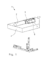
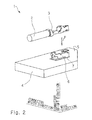
- a wire-to-board connector 1 includes a plug 3 (first terminal) which is attached to a wire 2, and a receptacle 6 (second terminal) which is mounted on a connector mounting surface 5 of a board 4.
- the plug 3 and the receptacle 6 are each formed of metal.
- the plug 3 and the receptacle 6 are formed by sheet metal bending.
- the plug 3 and the receptacle 6 are each a so-called insulator-less terminal (housing-less terminal) with no insulator.
- the plug 3 is mated with the receptacle 6, thereby allowing the wire 2 to be electrically connected to the board 4.
- wire direction refers to a direction corresponding to the longitudinal direction of the wire 2 in the vicinity of the plug 3 when the plug 3 is mated with the receptacle 6.
- the “wire direction” is set to be parallel to the connector mounting surface 5 of the board 4.
- a direction in which the plug 3 is viewed from the wire 2 is defined as a “wire plug direction”
- a direction in which the wire 2 is viewed from the plug 3 is defined as a "plug wire direction”.
- connector height direction refers to a direction orthogonal to the connector mounting surface 5 of the board 4.
- a direction approaching the connector mounting surface 5 of the board 4 is defined as a “board approaching direction” and a direction separating from the connector mounting surface 5 of the board 4 is defined as a “board separating direction”.
- the term “connector width direction” refers to a direction orthogonal to each of the wire direction and the connector height direction.
- a direction approaching the center of the wire-to-board connector 1 is defined as a “connector width center direction” and a direction separating from the center of the wire-to-board connector 1 is defined as a "connector width anti-center direction”.
- a mating direction P in which the plug 3 is mated with the receptacle 6 is a direction approaching the connector mounting surface 5 of the board 4. Accordingly, when other parts are disposed at a high density in the vicinity of the receptacle 6, for example, the workability that allows the plug 3 to be mated with the receptacle 6 is favorable.
- the mating direction P coincides with the board approaching direction. Accordingly, the workability that allows the plug 3 to be mated with the receptacle 6 is more favorable.
- the board 4 is a rigid board, such as a paper phenol board, in this embodiment.
- a flexible board can be used as the board 4.
- an electrode pad 7 to which the receptacle 6 is soldered is formed on the connector mounting surface 5 of the board 4.
- the wire 2 includes a strand wire 8 serving as a central conductor, and an insulation 9.
- the strand wire 8 is coated with the insulation 9.
- a solid wire can be used as the central conductor of the wire 2.
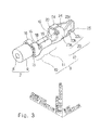
- Figs. 3 and 4 show the plug 3 in a state where the wire 2 is attached to the plug 3.
- the plug 3 is formed to be elongated along the wire direction.
- the plug 3 includes a wire holding portion 10, a wire connecting portion 11 (central conductor holding portion), and a plug body 12, which are formed in the stated order in the wire plug direction.
- the plug 3 is integrally formed with the wire holding portion 10, the wire connecting portion 11, and the plug body 12.
- the wire holding portion 10 is a portion that crimps and holds the insulation 9 of the wire 2.
- the wire holding portion 10 includes a base plate portion 15 and a pair of holding portions 16.
- the base plate portion 15 is a flat plate-like portion orthogonal to the connector height direction.
- the pair of holding portions 16 are respectively connected to both ends in the connector width direction of the base plate portion 15 and protrude in the board separating direction. An end in the board separating direction of each holding portion 16 is bent by a dedicated crimp tool and is thus curved in the connector width center direction.
- the wire connecting portion 11 is a portion that crimps and holds the strand wire 8 of the wire 2.
- the wire connecting portion 11 is electrically connected to the strand wire 8 of the wire 2.
- the wire connecting portion 11 includes a base plate portion 17 and a pair of holding portions 18.
- the base plate portion 17 is a flat plate-like portion orthogonal to the connector height direction.
- the base plate portion 17 is connected to an end in the wire plug direction of the base plate portion 15 of the wire holding portion 10.
- the pair of holding portions 18 are respectively connected to both ends in the connector width direction of the base plate portion 17 and protrude in the board separating direction.
- Each holding portion 18 is bent by a dedicated crimp tool and is thus curved in a C-shape in the connector width center direction.
- Each holding portion 18 is curved so as to swell out in the board separating direction.
- the plug body 12 includes a base plate portion 19, an erect rod guide portion 20, a pair of contact beams 23, a pair of pushing plate portions 24, and a pair of contact piece guide portions 25.
- the base plate portion 19 is a flat plate-like portion orthogonal to the connector height direction.
- the base plate portion 19 is connected to an end in the wire plug direction of the base plate portion 17 of the wire connecting portion 11.
- the erect rod guide portion 20 is a flat plate-like portion orthogonal to the connector height direction.
- the erect rod guide portion 20 is connected to an end in the wire plug direction of the base plate portion 19.
- the erect rod guide portion 20 has an erect rod guide hole portion 22 (guide hole portion) formed therein.
- the erect rod guide hole portion 22 is formed so as to penetrate a substantially central portion of the erect rod guide portion 20 in the connector height direction.
- the pair of contact beams 23, the pair of pushing plate portions 24, and the pair of contact piece guide portions 25 are each formed in a symmetrical shape in the connector width direction. Accordingly, only one of each pair will be described, and the description of the other one of each pair will be omitted.
- the contact beam 23 is a portion that functions as a contact with the receptacle 6.
- the contact beam 23 is formed in a beam shape.
- the contact beam 23 is formed in a cantilever shape.
- the contact beam 23 is a cantilever supported by the base plate portion 19.
- the contact beam 23 is connected to an end in the connector width direction of the base plate portion 19, and is positioned so as to be erected at a right angle with respect to the base plate portion 19.
- the contact beam 23 is formed so as to extend in the wire plug direction when viewed from the base plate portion 19.
- the contact beam 23 includes a proximal end 23a, an inclined portion 23b, and a distal end 23c, which are formed in the stated order in the wire plug direction.
- the proximal end 23a is a flat plate-like portion that is connected to an end in the connector width direction of the base plate portion 19 and is orthogonal to the connector width direction.
- the inclined portion 23b is a flat plate-like portion that is connected to an end in the wire plug direction of the proximal end 23a and is inclined in the connector width center direction toward the wire plug direction.
- the distal end 23c is a flat plate-like portion that is connected to an end in the wire plug direction of the inclined portion 23b and is orthogonal to the connector width direction.
- the distance between the distal end 23c of one of the contact beams 23 and the distal end 23c of the other contact beam 23 is smaller than the distance between the proximal end 23a of one of the contact beams 23 and the proximal end 23a of the other contact beam 23.
- the distance between the distal end 23c of one of the contact beams 23 and the distal end 23c of the other contact beam 23 is set to be smaller than the thickness of the receptacle 6.
- the distance between the distal end 23c of one of the contact beams 23 and the distal end 23c of the other contact beam 23 is set to be smaller than the thickness of a contact piece 47 (also see Fig. 5 ) of the receptacle 6 which is described later. Due to the presence of the proximal end 23a and the inclined portion 23b, the distal end 23c is elastically displaceable in the connector width anti-center direction.
- the pushing plate portion 24 is a flat plate-like portion that is connected to an end in the board separating direction of the proximal end 23a of the contact beam 23 and extends in the connector width center direction.
- the pushing plate portion 24 is orthogonal to the connector height direction. Accordingly, it can be said that the pushing plate portion 24 is disposed opposite to the board 4 with the contact beam 23 interposed therebetween.
- the distance between one of the pushing plate portions 24 and the other pushing plate portion 24 is set to be as small as possible.
- the contact piece guide portion 25 is a flat plate-like portion that is connected to an end in the board approaching direction of the distal end 23c of the contact beam 23 and is inclined in the connector width anti-center direction toward the board approaching direction.
- the receptacle 6 is formed to be elongated in the wire direction.
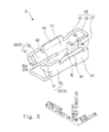
- the receptacle 6 includes a base plate portion 40, a pair of side plate portions 41, an erect rod 42 (guide rod portion), a contact unit 43, a pair of guide inclined portions 44 (inclined portions), and a pair of lock units 49.
- the base plate portion 40 is a portion that is soldered to the electrode pad 7 (see Figs. 1 and 2 ) on the connector mounting surface 5 of the board 4.
- the base plate portion 40 is formed in a flat plate shape orthogonal to the connector height direction.
- the base plate portion 40 has a rectangular shape and is formed to be elongated along the wire direction.
- the pair of side plate portions 41 is formed in a symmetrical shape in the connector width direction. Accordingly, only one of the pair will be described, and the description of the other one of the pair will be omitted.
- the side plate portion 41 is connected to an end in the connector width direction at an end in the wire plug direction of the base plate portion 40, and is formed to protrude in the board separating direction.
- the side plate portion 41 is positioned so as to be erected at a right angle with respect to the base plate portion 40. That is, the side plate portion 41 is in a position orthogonal to the connector width direction.
- the length of the side plate portion 41 in the wire direction is one-third of the length of the base plate portion 40 in the wire direction.
- the erect rod 42 is a portion that is disposed at the center of the receptacle 6 in the connector width direction and is formed in a rod shape extending in the board separating direction from the base plate portion 40.
- the erect rod 42 is formed by lancing the end in the wire plug direction of the base plate portion 40.
- the erect rod 42 is positioned so as to be erected at a right angle with respect to the base plate portion 40.
- the contact unit 43 is a portion that functions as a contact with the plug 3.
- the contact unit 43 is disposed at a location closer to a side in the wire plug direction than the base plate portion 40, the pair of side plate portions 41, and the erect rod 42.
- the contact unit 43 is supported by one of the side plate portion 41.
- the contact unit 43 includes a unit proximal end 45, a unit intermediate portion 46, and the contact piece 47.
- the unit proximal end 45 is a portion that is connected to an end in the wire plug direction of one of the side plate portions 41 and extends in the wire plug direction.
- the unit proximal end 45 is orthogonal to the connector width direction.
- the unit intermediate portion 46 is a portion that is connected to an end in the wire plug direction of the unit proximal end 45 and extends in the connector width center direction.
- the unit intermediate portion 46 is orthogonal to the wire direction.
- the unit intermediate portion 46 extends to the center in the connector width direction of the receptacle 6.
- the contact piece 47 is a portion that is connected to an end in the connector width center direction of the unit intermediate portion 46 and extends in the plug wire direction.
- the contact piece 47 is orthogonal to the connector width direction.
- a pair of inclined surfaces 48 is formed in such a manner that the end in the board separating direction of the contact piece 47 is tapered in the board separating direction.
- the contact unit 43 Due to the presence of the unit proximal end 45, the unit intermediate portion 46, and the contact piece 47, the contact unit 43 forms a U-shape when viewed along the board approaching direction. As shown in Fig. 6 , the contact piece 47 of the contact unit 43 is formed so as to be away from the base plate portion 40. As shown in Fig. 7 , the contact piece 47 is supported by one of the side plate portions 41 in a slightly floating state relative to the base plate portion 40 so that a gap "g" is formed between the contact piece 47 and the electrode pad 7 when the receptacle 6 is soldered to the electrode pad 7 on the connector mounting surface 5 of the board 4. To put it briefly, the contact piece 47 is disposed at a location farther from the board 4 than the base plate portion 40.
- the pair of lock units 49 constitutes a lock mechanism R.
- the pair of lock units 49 is formed in a symmetrical shape in the connector width direction. Accordingly, only one of the pair will be described, and the description of the other one of the pair will be omitted.
- the lock unit 49 includes a lock beam 50 and a claw portion 51.
- the lock beam 50 is formed in a beam shape that is supported by the side plate portion 41.
- the lock beam 50 is formed in a cantilever shape that is supported by the side plate portion 41.
- the lock beam 50 is a flat plate-like portion that is connected to an end in the plug wire direction of the side plate portion 41 and extends in the plug wire direction.
- the lock beam 50 is orthogonal to the connector width direction. As shown in Fig. 7 , an end in the plug wire direction of the lock beam 50 is positioned in the vicinity of an end in the plug wire direction of the base plate portion 40.
- the claw portion 51 is a portion that is connected to an end in the plug wire direction of the lock beam 50 and is formed so as to protrude in the connector width center direction.
- the claw portion 51 has an inclined surface 51a that is inclined in the board approaching direction toward the connector width center direction. In the structure described above, the claw portion 51 is elastically displaceable in the connector width anti-center direction due to the presence of the lock beam 50.
- the pair of guide inclined portions 44 is formed in a symmetrical shape in the connector width direction. Accordingly, only one of the pair will be described, and the description of the other one of the pair will be omitted.
- the guide inclined portion 44 is connected to an end in the board separating direction of the side plate portion 41 and to an end in the board separating direction of the lock beam 50.
- the guide inclined portion 44 is formed so as to extend in the wire direction.
- the guide inclined portion 44 is inclined in the board approaching direction toward the connector width center direction. That is, the pair of guide inclined portions 44 is inclined so as to be spaced apart from each other toward the board separating direction.
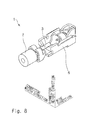
- FIG. 8 shows a state in which the plug 3 is mated with the receptacle 6.
- the wire 2 is attached to the plug 3, and the plug 3 is moved toward the receptacle 6.
- the direction of movement of the plug 3 toward the receptacle 6 is indicated by the above-mentioned mating direction P.
- the plug 3 is moved toward the receptacle 6 in such a manner that the erect rod 42 shown in Fig. 5 is inserted into the erect rod guide hole portion 22 shown in Fig. 4 .
- the position of the plug 3 in the connector width direction relative to the receptacle 6 is automatically adjusted.
- the end in the board separating direction of the erect rod 42 is inserted into the erect rod guide hole portion 22 by moving the plug 3 in the wire direction relative to the receptacle 6 in a reciprocating manner, or by visual checking, thereby determining the position of the plug 3 in the wire direction and the connector width direction relative to the receptacle 6.
- the pair of contact piece guide portions 25 shown in Fig. 4 contact the pair of inclined surfaces 48 of the contact piece 47 shown in Fig. 5
- the base plate portion 17 of the wire connecting portion 11 shown in Fig. 4 contacts the inclined surfaces 51a of the pair of claw portions 51 shown in Fig. 5 .
- the first preferred embodiment of the present invention described above has the following features.
- the plug 3 of this embodiment is identical with the plug 3 of the first embodiment, so the description thereof is omitted.
- the receptacle 6 is formed to be elongated in the wire direction.
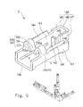
- the receptacle 6 includes a base plate portion 140, a pair of side plate portions 141, an erect rod 142 (guide rod portion), a contact unit 143, a pair of guide inclined portions 144 (inclined portions), and a pair of lock units 149.
- the base plate portion 140 is a portion that is soldered to the electrode pad 7 (see Figs. 1 and 2 ) of the connector mounting surface 5 of the board 4.
- the base plate portion 140 is formed in a flat plate shape that is orthogonal to the connector height direction.
- the base plate portion 140 has a rectangular shape and is formed so as to be tapered along the wire direction.
- the pair of side plate portions 141 is formed in a symmetrical shape in the connector width direction. Accordingly, only one of the pair will be described, and the description of the other one of the pair will be omitted.
- the side plate portion 141 is connected to an end in the connector width direction of the base plate portion 140, and is formed to protrude in the board separating direction.
- the side plate portion 141 is connected to an end in the plug wire direction of the base plate portion 140 and to an end in the wire plug direction thereof.
- the side plate portion 141 and the base plate portion 140 are not connected to each other between the end in the plug wire direction of the base plate portion 140 and the end in the wire plug direction thereof, and a slit "s" is formed between the side plate portion 141 and the base plate portion 140.
- This slit "s" facilitates the elastic deformation of the side plate portion 141 so that it is inclined in the connector width anti-center direction.
- the side plate portion 141 is positioned so as to be erected at a right angle with respect to the base plate portion 140. That is, the side plate portion 141 is in a position orthogonal to the connector width direction.
- the length in the wire direction of the side plate portion 141 is equal to the length in the wire direction of the base plate portion 140.
- the erect rod 142 is a portion that is disposed at the center in the connector width direction of the receptacle 6 and is formed in a rod shape extending in the board separating direction from the base plate portion 140.
- the erect rod 142 is formed by lancing the end in the wire plug direction of the base plate portion 140.
- the erect rod 142 is positioned so as to be erected at a right angle with respect to the base plate portion 140.
- the contact unit 143 is a portion that functions as a contact with the plug 3.
- the contact unit 143 is disposed at a location closer to a side in the wire plug direction than the base plate portion 140, the pair of side plate portions 141, and the erect rod 142.
- the contact unit 143 is supported by one of the side plate portions 141.
- the contact unit 143 includes a unit proximal end 145, a unit intermediate portion 146, and a contact piece 147.
- the unit proximal end 145 is a portion that is connected to an end in the wire plug direction of one of the side plate portions 141 and extends in the wire plug direction.
- the unit proximal end 145 is orthogonal to the connector width direction.
- the unit intermediate portion 146 is a portion that is connected to an end in the wire plug direction of the unit proximal end 145 and extends in the connector width center direction.
- the unit intermediate portion 146 is orthogonal to the wire direction.
- the unit intermediate portion 146 extends to the center in the connector width direction of the receptacle 6.
- the contact piece 147 is a portion that is connected to an end in the connector width center direction of the unit intermediate portion 146 and extends in the plug wire direction.
- the contact piece 147 is orthogonal to the connector width direction.
- a pair of inclined surfaces 148 is formed in such a manner that the end in the board separating direction of the contact piece 147 is tapered in the board separating direction.
- the contact unit 143 Due to the presence of the unit proximal end 145, the unit intermediate portion 146, and the contact piece 147, the contact unit 143 forms a U-shape when viewed along the board approaching direction.
- the contact piece 147 of the contact unit 143 is formed so as to be away from the base plate portion 140 (also see Fig. 6 ).
- the contact piece 147 is supported by one of the side plate portions 141 in a slightly floating state relative to the base plate portion 140 so that the gap "g" (also see Fig. 7 ) is formed between the contact piece 147 and the electrode pad 7 when the receptacle 6 is soldered to the electrode pad 7 on the connector mounting surface 5 of the board 4.
- the contact piece 147 is disposed at a location farther from the board 4 than the base plate portion 140.
- the pair of lock units 149 constitutes the lock mechanism R.
- the pair of lock units 149 is formed in a symmetrical shape in the connector width direction. Accordingly, only one of the pair will be described, and the description of the other one of the pair will be omitted.
- the lock unit 149 includes a standing portion 153, a curved portion 154, and an inclined portion 155.
- the standing portion 153 is a flat plate-like portion that is connected to an end in the board separating direction of the side plate portion 141 and extends in the board separating direction.
- the standing portion 153 is orthogonal to the connector width direction.
- the standing portion 153 is disposed at a location slightly closer to the side in the plug wire direction relative to the center in the wire direction of the side plate portion 141.
- the curved portion 154 is a portion that is connected to an end in the board separating direction of the standing portion 153 and is curved in the connector width center direction.
- the inclined portion 155 is a portion that is connected to an end in the connector width center direction of the curved portion 154 and is inclined in the board approaching direction toward the connector width center direction.
- the inclined portion 155 has an inclined surface 155a that is inclined in the board approaching direction toward the connector width center direction.
- the inclined portion 155 (inclined surface 155a) is elastically displaceable in the connector width anti-center direction.
- the pair of guide inclined portions 144 is formed in a symmetrical shape in the connector width direction. Accordingly, only one of the pair will be described, and the description of the other one of the pair will be omitted.
- the guide inclined portion 144 is connected to an end in the board separating direction of the side plate portion 141 and is formed so as to extend in the wire direction.
- the guide inclined portion 144 is disposed at a location closer to a side in the wire plug direction than the lock unit 149.
- the guide inclined portion 144 is inclined in the board approaching direction toward the connector width center direction. That is, the pair of guide inclined portions 144 is inclined so as to be spaced apart from each other toward the board separating direction.
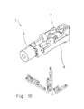
- FIG. 10 shows a state in which the plug 3 is mated with the receptacle 6.
- the wire 2 is attached to the plug 3 (also see Fig. 2 ), and the plug 3 is moved toward the receptacle 6.
- the direction of movement of the plug 3 toward the receptacle 6 is indicated by the above-mentioned mating direction P.
- the plug 3 is moved toward the receptacle 6 in such a manner that the erect rod 142 shown in Fig. 9 is inserted into the erect rod guide hole portion 22 shown in Fig. 4 .
- the position of the plug 3 in the connector width direction relative to the receptacle 6 is automatically adjusted.
- the end in the board separating direction of the erect rod 142 is inserted into the erect rod guide hole portion 22 by moving the plug 3 in the wire direction relative to the receptacle 6 in a reciprocating manner, thereby determining the position of the plug 3 in the wire direction and the connector width direction relative to the receptacle 6.
- the pair of contact piece guide portions 25 shown in Fig. 4 contact the pair of inclined surfaces 148 of the contact piece 147 shown in Fig. 9
- the base plate portion 17 of the wire connecting portion 11 shown in Fig. 4 contacts the inclined surfaces 155a shown in Fig. 9 .
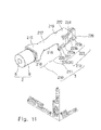
- Figs. 11 and 12 show the plug 3 in a state where the wire 2 is attached to the plug 3.
- the plug 3 is formed to be elongated along the wire direction.
- the plug 3 includes a wire holding portion 210, a wire connecting portion 211 (central conductor holding portion), and a plug body 212, which are formed in the stated order in the wire plug direction.
- the plug 3 is integrally formed with the wire holding portion 210, the wire connecting portion 211, and the plug body 212.
- the wire holding portion 210 is a portion that crimps and holds the insulation 9 of the wire 2.
- the wire holding portion 210 includes a base plate portion 215 and a pair of holding portions 216.
- the base plate portion 215 is a flat plate-like portion orthogonal to the connector height direction.
- the pair of holding portions 216 are respectively connected to both ends in the connector width direction of the base plate portion 215, and protrude in the board approaching direction. An end in the board approaching direction of each holding portion 216 is bent by a dedicated crimp tool, and is thus curved in the connector width center direction.
- the wire connecting portion 211 is a portion that crimps and holds the strand wire 8 of the wire 2.
- the wire connecting portion 211 is electrically connected to the strand wire 8 of the wire 2.
- the wire connecting portion 211 includes a base plate portion 217 and a pair of holding portions 218.
- the base plate portion 217 is a flat plate-like portion orthogonal to the connector height direction.
- the base plate portion 217 is connected to an end in the wire plug direction of the base plate portion 215 of the wire holding portion 210.
- the pair of holding portions 218 are respectively connected to both ends in the connector width direction of the base plate portion 217, and protrude in the board approaching direction.
- Each holding portion 218 is bent by a dedicated crimp tool, and is thus curved in the connector width center direction.
- Each holding portion 218 is curved so as to swell out in the board separating direction.
- the plug body 212 includes a base plate portion 219, a pushing plate portion 220, a pair of contact beams 223, a pair of erect rod guide portions 224, a pair of lock units 225, and a pair of contact piece guide portions 226.
- the base plate portion 219 is a flat plate-like portion orthogonal to the connector height direction.
- the base plate portion 219 is connected to an end in the wire plug direction of the base plate portion 217 of the wire connecting portion 211.
- the pushing plate portion 220 is a plate-like portion orthogonal to the connector height direction.
- the pushing plate portion 220 is connected to an end in the wire plug direction of the base plate portion 219.
- the pair of contact beams 223, the pair of erect rod guide portions 224, the pair of lock units 225, and the pair of contact piece guide portions 226 are each formed in a symmetrical shape in the connector width direction. Accordingly, only one of each pair will be described, and the description of the other one of each pair will be omitted.
- the contact beam 223 is a portion that functions as a contact with the receptacle 6.
- the contact beam 223 is formed in a beam shape.
- the contact beam 223 is formed in a cantilever shape.
- the contact beam 223 is a cantilever supported by the base plate portion 219.
- the contact beam 223 is connected to an end in the connector width direction of the base plate portion 219, and is positioned so as to be erected at a right angle with respect to the base plate portion 219.
- the contact beam 223 is formed so as to extend in the wire plug direction when viewed from the base plate portion 219.
- the contact beam 223 includes a proximal end 223a, an inclined portion 223b, and a distal end 223c, which are formed in the stated order in the wire plug direction.
- the proximal end 223a is a flat plate-like portion that is connected to an end in the connector width direction of the base plate portion 219 and is orthogonal to the connector width direction.
- the inclined portion 223b is a flat plate-like portion that is connected to an end in the wire plug direction of the proximal end 223a and is inclined in the connector width center direction toward the wire plug direction.
- the distal end 223c is a flat plate-like portion that is connected to an end in the wire plug direction of the inclined portion 223b and is orthogonal to the connector width direction.
- the distance between the distal end 223c of one of the contact beams 223 and the distal end 223 of the other contact beam 223 is smaller than the distance between the proximal end 223a of one of the contact beams 223 and the proximal end 223a of the other contact beam 223.
- the distance between the distal end 223c of one of the contact beams 223 and the distal end 223c of the other contact beam 223 is set to be smaller than the thickness of the receptacle 6. Due to the presence of the proximal end 223a and the inclined portion 223b, the distal end 223c is elastically displaceable in the connector width anti-center direction.
- the contact beam 223 is disposed between the pushing plate portion 220 and the board 4 in the connector height direction. That is, it can be said that the pushing plate portion 220 is disposed opposite to the board 4 with the contact beam 223 interposed therebetween.
- the erect rod guide portion 224 is a flat plate-like portion that is connected to an end in the board approaching direction of the proximal end 223a of the contact beam 223 and extends in the wire plug direction.
- the erect rod guide portion 224 is orthogonal to the connector height direction.
- a notch 224a which is opened in the connector width center direction is formed.
- the distance between one of the erect rod guide portions 224 and the other erect rod guide portion 224 is set to be as small as possible.
- the notch 224a of one of the erect rod guide portion 224 and the notch 224a of the other erect rod guide portion 224 constitute an erect rod guide hole portion 222 (guide hole portion).
- the lock unit 225 includes a lock beam 227 and a claw portion 228.
- the lock beam 227 is a portion that is connected to the proximal end 223a of the contact beam 223 and extends in a rod shape in the board approaching direction.
- the lock beam 227 is formed in a cantilever shape that is supported by the proximal end 223a.
- the claw portion 228 is a portion that is connected to an end in the board approaching direction of the lock beam 227 and protrudes in the plug wire direction.
- the contact piece guide portion 226 is a flat plate-like portion that is connected to an end in the board approaching direction of the distal end 223c of the contact beam 223 and is inclined in the connector width anti-center direction toward the board approaching direction.
- the receptacle 6 is formed to be elongated in the wire direction.
- the receptacle 6 includes a base plate portion 240, a pair of side plate portions 241, an erect rod 242 (guide rod portion), and a contact unit 243.
- the base plate portion 240 is a portion that is soldered to the electrode pad 7 (see Figs. 1 and 2 ) on the connector mounting surface 5 of the board 4.
- the base plate portion 240 is formed to be elongated in the wire direction.
- the base plate portion 240 includes a first soldered portion 240a, a lock plate portion 240b, and a second soldered portion 240c, which are formed in the stated order in the wire plug direction.
- the first soldered portion 240a is formed in a flat plate shape orthogonal to the connector height direction.
- the lock plate portion 240b is connected to an end in the wire plug direction of the first soldered portion 240a, is slightly raised in the board separating direction relative to the first soldered portion 240a, and is formed in a flat plate shape orthogonal to the connector height direction.
- a pair of lock hole portions 240d are respectively formed at both ends in the connector width direction of the lock plate portion 240b.
- the second soldered portion 240c is connected to an end in the wire plug direction of the lock plate portion 240b, is slightly recessed in the board approaching direction relative to the lock plate portion 240b, and is formed in a flat plate shape orthogonal to the connector height direction.
- the first soldered portion 240a and the second soldered portion 240c are soldered to the electrode pad 7 on the connector mounting surface 5 of the board 4.
- the pair of side plate portions 241 is formed in a symmetrical shape in the connector width direction. Accordingly, only one of the pair will be described, and the description of the other one of the pair will be omitted.
- the side plate portion 241 is connected to an end in the connector width direction of the second soldered portion 240c of the base plate portion 240, and is formed to protrude in the board separating direction.
- the side plate portion 241 is positioned so as to be erected at a right angle with respect to the base plate portion 240. That is, the side plate portion 241 is in a position orthogonal to the connector width direction.
- the erect rod 242 is a portion that is disposed at the center in the connector width direction of the receptacle 6 and is formed in a rod shape extending in the board separating direction from the base plate portion 240.
- the erect rod 242 is formed by lancing an end in the wire plug direction of the second soldered portion 240c of the base plate portion 240.
- the erect rod 242 is positioned so as to be erected at a right angle with respect to the second soldered portion 240c of the base plate portion 240.
- the contact unit 243 is a portion that functions as a contact with the plug 3.
- the contact unit 243 is disposed at a location closer to a side in the wire plug direction than the base plate portion 240, the pair of side plate portions 241, and the erect rod 242.
- the contact unit 243 is supported by one of the side plate portions 241.
- the contact unit 243 includes a unit proximal end 245, a unit intermediate portion 246, and a contact piece 247.
- the unit proximal end 245 is a portion that is connected to an end in the wire plug direction of one of the side plate portions 241.
- the unit proximal end 245 is orthogonal to the connector width direction.
- the unit intermediate portion 246 is a portion that is connected to an end in the wire plug direction of the unit proximal end 245 and extends in the connector width center direction.
- the unit intermediate portion 246 is orthogonal to the wire direction.
- the unit intermediate portion 246 extends to the center in the connector width direction of the receptacle 6.
- the contact piece 247 is a portion that is connected to an end in the connector width center direction of the unit intermediate portion 246 and extends in the plug wire direction.
- the contact piece 247 is orthogonal to the connector width direction.
- a pair of inclined surfaces 248 is formed in such a manner that the end in the board separating direction of the contact piece 247 is tapered in the board separating direction.
- the contact unit 243 Due to the presence of the unit proximal end 245, the unit intermediate portion 246, and the contact piece 247, the contact unit 243 forms a U-shape when viewed along the board approaching direction. As shown in Fig. 14 , the contact piece 247 of the contact unit 243 is formed so as to be away from the base plate portion 240. The contact piece 247 is supported by one of the side plate portions 241 in a slightly floating state relative to the base plate portion 240 so that the gap "g" (also see Fig. 7 ) is formed between the contact piece 247 and the electrode pad 7 when the receptacle 6 is soldered to the electrode pad 7 on the connector mounting surface 5 of the board 4. To put it briefly, the contact piece 247 is disposed at a location farther from the board 4 than the base plate portion 240.
- FIG. 15 shows a state in which the plug 3 is mated with the receptacle 6.
- the wire 2 is attached to the plug 3, and the plug 3 is moved toward the receptacle 6.
- the direction of movement of the plug 3 toward the receptacle 6 is indicated by the above-mentioned mating direction P.
- the plug 3 is moved toward the receptacle 6 in such a manner that the erect rod 242 shown in Fig. 13 is inserted into the erect rod guide hole portion 222 shown in Fig. 12 .
- the position of the plug 3 in the wire direction and the connector width direction relative to the receptacle 6 is determined.
- the pair of contact piece guide portions 226 shown in Fig. 12 contacts the pair of inclined surfaces 248 of the contact piece 247 shown in Fig. 13
- the claw portions 228 of the pair of lock units 225 shown in Fig. 11 contact the periphery of the lock hole portions 240d of the pair of lock plate portions 240b shown in Fig. 13 .
- the wire-to-board connector 1 includes the plug 3 which is attached to the wire 2, and the receptacle 6 which is mounted on the connector mounting surface 5 of the board 4.
- the plug 3 and the receptacle 6 are each formed of metal.
- the plug 3 and the receptacle 6 are formed by sheet metal bending.
- Each of the plug 3 and the receptacle 6 is a so-called insulator-less terminal (housing-less terminal) with no insulator.
- the plug 3 is mated with the receptacle 6, thereby allowing the wire 2 to be electrically connected to the board 4.
- the mating direction P in which the plug 3 is mated with the receptacle 6 is a direction approaching the connector mounting surface 5 of the board 4. Accordingly, the workability that allows the plug 3 to be mated with the receptacle 6 is favorable.
- the mating direction P coincides with the board approaching direction. Accordingly, the workability that allows the plug 3 to be mated with the receptacle 6 is more favorable.
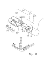
- Figs. 18 and 19 show the plug 3 in a state where the wire 2 is attached to the plug 3.
- the plug 3 is formed to be elongated along the wire direction.
- the plug 3 includes a wire holding portion 310, a wire connecting portion 311 (central conductor holding portion), and a plug body 312, which are formed in the stated order in the wire plug direction.
- the plug 3 is integrally formed with the wire holding portion 310, the wire connecting portion 311, and the plug body 312.
- the wire holding portion 310 is a portion that crimps and holds the insulation 9 of the wire 2.
- the wire holding portion 310 includes a base plate portion 315 and a pair of holding portions 316.
- the base plate portion 315 is a flat plate-like portion orthogonal to the connector height direction.
- the pair of holding portions 316 are respectively connected to both ends in the connector width direction of the base plate portion 315, and protrude in the board approaching direction. An end in the board approaching direction of each holding portion 316 is bent by a dedicated crimp tool, and is thus curved in the connector width center direction.
- the wire connecting portion 311 is a portion that crimps and holds the strand wire 8 of the wire 2.
- the wire connecting portion 311 is electrically connected to the strand wire 8 of the wire 2.
- the wire connecting portion 311 includes a base plate portion 317 and a pair of holding portions 318.
- the base plate portion 317 is a flat plate-like portion orthogonal to the connector height direction.
- the base plate portion 317 is connected to an end in the wire plug direction of the base plate portion 315 of the wire holding portion 310.
- the pair of holding portions 318 are respectively connected to both ends in the connector width direction of the base plate portion 317 and protrude in the board approaching direction.
- Each holding portion 318 is bent by a dedicated crimp tool, and is thus curved in a C-shape toward the connector width center direction.
- Each holding portion 318 is curved so as to swell out in the board approaching direction.
- the plug body 312 includes a base plate portion 319, a pair of contact beams 320, and a pair of protrusions 327.
- the base plate portion 319 is a flat plate-like portion that is connected to an end in the wire plug direction of the base plate portion 317 of the wire connecting portion 311 and extends in the wire plug direction.
- the base plate portion 319 is orthogonal to the connector height direction.
- a slit 321 which extends in the wire direction is formed.
- the base plate portion 319 includes a distal end inner wall surface 321 a which defines a space in the wire plug direction of the slit 321, and a proximal end inner wall surface 321b which defines a space in the plug wire direction of the slit 321.
- the pair of contact beams 320 and the pair of protrusions 327 are each formed in a symmetrical shape in the connector width direction. Accordingly, only one of each pair will be described, and the description of the other one of each pair will be omitted.
- the contact beam 320 is a portion that functions as a contact with the receptacle 6.
- the contact beam 320 is formed in a beam shape.
- the contact beam 320 is formed in a cantilever shape.
- the contact beam 320 is a cantilever supported by the base plate portion 319.
- the contact beam 320 is connected to an end in the connector width direction of the base plate portion 319 and is positioned so as to be erected at a right angle with respect to the base plate portion 319.
- the contact beam 320 is a cantilever which is formed in a U-shape that is opened in the plug wire direction when viewed along the board separating direction.
- the contact beam 320 includes a side plate portion 322, a curved portion 323, an inclined portion 324, and a contact portion 325.
- the side plate portion 322 is a portion that is connected to an end in the connector width direction of the base plate portion 319 and extends in the wire plug direction.
- the side plate portion 322 is orthogonal to the connector width direction.
- a lock hole portion 326 having a rectangular shape is formed on a side in the plug wire direction of the side plate portion 322.
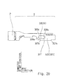
- the side plate portion 322 includes a board-side inner wall surface 326a which defines a space in the board approaching direction of the lock hole portion 326, a plug-side inner wall surface 326b which defines a space in the wire plug direction of the lock hole portion 326, and a wire-side inner wall surface 326c which defines a space in the plug wire direction of the lock hole portion 326.
- the board-side inner wall surface 326a is formed so as to be inclined in the board approaching direction toward the wire plug direction.
- the plug-side inner wall surface 326b and the wire-side inner wall surface 326c are orthogonal to the wire direction.
- the curved portion 323 is a portion that is connected to an end in the wire plug direction of the side plate portion 322 and is curved in a C-shape toward the connector width center direction.
- the inclined portion 324 is a portion that is connected to an end on a side opposite to the side plate portion 322 of the curved portion 323 and extends in the plug wire direction.
- the inclined portion 324 is inclined in the connector width center direction toward the plug wire direction when viewed along the board separating direction.
- the contact portion 325 is a portion that is connected to an end in the plug wire direction of the inclined portion 324 and extends in the plug wire direction.
- the distance between the contact portion 325 of one of the contact beams 320 and the contact portion 325 of the other contact beam 320 is set to be smaller than the thickness of the receptacle 6. Due to the presence of the inclined portion 324 and the curved portion 323, the contact portion 325 is elastically deformable in the connector width anti-center direction.
- the protrusion 327 is a portion that protrudes in the board approaching direction in a central portion in the wire direction of the side plate portion 322. As shown in Fig. 20 , the protrusion 327 includes a plug-side end face 327a which is an end face in the wire plug direction of the protrusion 327, and a wire-side end face 327b which is an end face in the plug wire direction of the protrusion 327.
- the receptacle 6 is formed to be elongated in the wire direction.
- the receptacle 6 includes a base plate portion 340, a pair of lock beams 341, and a contact unit 342.
- the base plate portion 340 is a portion that is soldered to the electrode pad 7 (see Figs. 16 and 17 ) on the connector mounting surface 5 of the board 4.
- the base plate portion 340 is formed to be elongated in the wire direction.
- the base plate portion 340 is orthogonal to the connector height direction.
- Notches 343 which are opened in the connector width anti-center direction are respectively formed at both ends in the connector width direction of the base plate portion 340.
- the pair of notches 343 is formed on a side in the wire plug direction of the base plate portion 340.
- the base plate portion 340 includes a plug-side inner wall surface 343a which defines a space in the wire plug direction of the notches 343, and a wire-side inner wall surface 343b which defines an area on the side in the wire plug direction of the notches 343.
- the pair of lock beams 341 is formed in a symmetrical shape in the connector width direction. Accordingly, only one of the pair will be described, and the description of the other one of the pair will be omitted.
- the lock beam 341 is connected to an end in the plug wire direction of the base plate portion 340 and is formed so as to extend in the wire plug direction.
- the lock beam 341 is positioned so as to be erected at a right angle with respect to the base plate portion 340.
- the lock beam 341 is orthogonal to the connector width direction.
- a lock raised portion 344 that is raised in the connector width center direction is formed.
- the lock raised portion 344 is formed at an end in the board approaching direction of the end in the wire plug direction of the lock beam 341.
- the lock raised portion 344 includes a plug-side end face 344a that faces in the wire plug direction, and a board-side end face 344b that faces in the board approaching direction.
- the lock raised portion 344 is elastically displaceable in the connector width anti-center direction, while the lock beam 341 is elastically deformed. Note that the length in the wire direction of the lock beam 341 is three-quarters of the length in the wire direction of the base plate portion 340.
- the contact unit 342 is a portion that functions as a contact with the plug 3.
- the contact unit 342 is supported by the base plate portion 340.
- the contact unit 342 includes a unit proximal end 345 and a contact piece 346.
- the unit proximal end 345 is a portion that is connected to an end in the wire plug direction of the base plate portion 340 and protrudes in the board separating direction.
- the unit proximal end 345 is connected to a portion on one side in the connector width direction of the end in the wire plug direction of the base plate portion 340.
- the unit proximal end 345 is orthogonal to the wire direction.
- the contact piece 346 is connected to an end in the connector width center direction of the unit proximal end 345 and is formed so as to extend in the plug wire direction.
- the contact piece 346 is orthogonal to the connector width direction.
- the contact piece 346 has a tapered portion 347 that protrudes in the board separating direction.
- the tapered portion 347 is formed at an end in the board separating direction of the contact piece 346.
- the tapered portion 347 is formed on a side in the plug wire direction of the contact piece 346.
- the tapered portion 347 has a pair of inclined surfaces 348 in such a manner that the tapered portion 347 is tapered in the board separating direction.
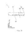
- the tapered portion 347 includes a plug-side end face 347a that faces in the wire plug direction, and a wire-side end face 347b that faces in the plug wire direction. Due to the presence of the unit proximal end 345 and the contact piece 346, the contact unit 342 forms an L-shape when viewed along the board approaching direction. As shown in Fig. 23 , the contact piece 346 of the contact unit 342 is formed so as to be away from the base plate portion 340. That is, a gap "h" is formed between the contact piece 346 of the contact unit 342 and the base plate portion 340. To put it briefly, the contact piece 346 is disposed at a location farther from the board 4 than the base plate portion 340.
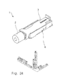
- FIGs. 24 and 25 show a state in which the plug 3 is mated with the receptacle 6.
- the wire 2 is attached to the plug 3, and the plug 3 is moved toward the receptacle 6.
- the direction of movement of the plug 3 toward the receptacle 6 is indicated by the above-mentioned mating direction P.
- the plug 3 is moved toward the receptacle 6 in such a manner that the side plate portions 322 of the pair of contact beams 320 of the plug body 312 of the plug 3 shown in Fig. 18 are fitted between the pair of lock beams 341 of the receptacle 6 shown in Fig. 21 .
- the pair of contact portions 325 shown in Fig. 19 contacts the pair of inclined surfaces 348 of the tapered portion 347 shown in Fig. 21
- the pair of side plate portions 322 shown in Fig. 19 contacts the pair of lock raised portions 344 shown in Fig. 21 .
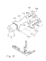
- Fig. 27 shows the plug 3 in a state where the wire 2 is attached to the plug 3.
- the plug 3 is formed to be elongated along the wire direction.
- the plug 3 includes a wire holding portion 410, a wire connecting portion 411 (central conductor holding portion), and a plug body 412, which are formed in the stated order in the wire plug direction.
- the plug 3 is integrally formed with the wire holding portion 410, the wire connecting portion 411, and the plug body 412.
- the wire holding portion 410 is a portion that crimps and holds the insulation 9 of the wire 2.
- the wire holding portion 410 includes a base plate portion 415 and a pair of holding portions 416.
- the base plate portion 415 is a flat plate-like portion orthogonal to the connector height direction.
- the pair of holding portions 416 are respectively connected to both ends in the connector width direction of the base plate portion 415, and protrude in the board approaching direction. An end in the board approaching direction of each holding portion 416 is bent by a dedicated crimp tool, and is thus curved in the connector width center direction.
- the wire connecting portion 411 is a portion that crimps and holds the strand wire 8 of the wire 2.
- the wire connecting portion 411 is electrically connected to the strand wire 8 of the wire 2.
- the wire connecting portion 411 includes a base plate portion 417 and a pair of holding portions 418.
- the base plate portion 417 is a flat plate-like portion orthogonal to the connector height direction.
- the base plate portion 417 is connected to an end in the wire plug direction of the base plate portion 415 of the wire holding portion 410.
- the pair of holding portions 418 are respectively connected to both ends in the connector width direction of the base plate portion 417, and protrude in the board approaching direction.
- Each holding portion 418 is bent by a dedicated crimp tool, and is thus curved in a C-shape toward the connector width center direction.
- Each holding portion 418 is curved so as to swell out in the board approaching direction.
- the plug body 312 includes a base plate portion 419 and a pair of contact beams 420.
- the base plate portion 419 is a flat plate-like portion that is connected to an end in the wire plug direction of the base plate portion 417 of the wire connecting portion 411 and extends in the wire plug direction.
- the base plate portion 419 is orthogonal to the connector height direction.
- a slit 421 which extends in the wire direction is formed.
- the base plate portion 419 includes a distal end inner wall surface 421 a which defines a space in the wire plug direction of the slit 421, and a proximal end inner wall surface 421b which defines a space in the plug wire direction of the slit 421.
- the pair of contact beams 420 is formed in a symmetrical shape in the connector width direction. Accordingly, only one of the pair will be described, and the description of the other one of the pair will be omitted.
- the contact beam 420 is a portion that functions as a contact with the receptacle 6.
- the contact beam 420 is formed in a beam shape.
- the contact beam 420 is formed in a cantilever shape.
- the contact beam 420 is a cantilever supported by the base plate portion 419.
- the contact beam 420 is connected to an end in the connector width direction of the base plate portion 419, and is positioned so as to be erected at a right angle with respect to the base plate portion 419.
- the contact beam 420 is a cantilever which is formed in a U-shape that is opened in the plug wire direction when viewed along the board separating direction.
- the contact beam 420 includes a side plate portion 422, a curved portion 423, an inclined portion 424, and a contact portion 425.
- the shape of the contact beam 420 is completely identical with the shape of the contact beam 320 of the fourth embodiment.
- the inclined portion 424 and the contact portion 425 also refer to the inclined portion 324 and the contact portion 325 shown in Fig. 19 .
- the side plate portion 422 is a portion that is connected to an end in the connector width direction of the base plate portion 419 and extends in the wire plug direction.
- the side plate portion 422 is orthogonal to the connector width direction.
- the lock claw portion 426 is formed by lancing a portion which is located on a side in the plug wire direction of the side plate portion 422.
- the lock claw portion 426 is formed as a cantilever which rolls back in the connector width anti-center direction toward the board separating direction. As shown in Fig.
- the lock claw portion 426 includes a plug-side end face 426a that faces in the wire plug direction, a wire-side end face 426b that faces in the plug wire direction, and a distal end face 426c that faces in substantially the board separating direction.
- the side plate portion 422 includes a protrusion 427 that protrudes in the board approaching direction.
- the protrusion 427 includes a plug-side end face 427a which is an end face in the wire plug direction of the protrusion 427.
- the curved portion 423 is a portion that is connected to an end in the wire plug direction of the side plate portion 422 and is curved in a C-shape toward the connector width center direction.
- the inclined portion 424 is a portion that is connected to an end on a side opposite to the side plate portion 422 of the curved portion 423 and extends in the plug wire direction.
- the inclined portion 424 is inclined in the connector width center direction toward the plug wire direction.
- the contact portion 425 is a portion that is connected to an end in the plug wire direction of the inclined portion 424 and extends in the plug wire direction.
- the distance between the contact portion 425 of one of the contact beams 420 and the contact portion 425 of the other contact beam 420 is set to be smaller than the thickness of the receptacle 6. Due to the presence of the inclined portion 424 and the curved portion 423, the contact portion 425 is elastically deformable in the connector width anti-center direction.
- the receptacle 6 is formed to be elongated in the wire direction.
- the receptacle 6 includes a base plate portion 440, a pair of side plate portions 441, and a contact unit 442.
- the base plate portion 440 is a portion that is soldered to the electrode pad 7 (see Figs. 16 and 17 ) of the connector mounting surface 5 of the board 4.
- the base plate portion 440 is formed to be elongated in the wire direction.
- the base plate portion 440 is orthogonal to the connector height direction.
- Notches 443 which are opened in the connector width anti-center direction are respectively formed at both ends in the connector width direction of the base plate portion 440.
- the pair of notches 443 is formed at the center in the wire direction of the base plate portion 440.
- the base plate portion 440 includes a plug-side inner wall surface 443 a which defines a space in the wire plug direction of the notches 443.
- the pair of side plate portions 441 is formed in a symmetrical shape in the connector width direction. Accordingly, only one of the pair will be described, and the description of the other one of the pair will be omitted.
- the side plate portion 441 is connected to an end in the plug wire direction of the base plate portion 440 and to an end in the wire plug direction thereof, and is formed so as to extend in the wire direction.
- the side plate portion 441 is positioned so as to be erected at a right angle with respect to the base plate portion 440.
- the side plate portion 441 is orthogonal to the connector width direction.
- the side plate portion 441 is elastically deformable so as to fall down in the connector width anti-center direction.
- a lock notch portion 444 which is opened in the board approaching direction is formed.
- the lock notch portion 444 is formed at an end in the board approaching direction of the side plate portion 441.
- the lock notch portion 444 is formed in a rectangular shape when viewed along the connector width center direction.
- the side plate portion 441 includes a lock surface 444a which defines a space in the board separating direction of the lock notch portion 444, a plug-side inner wall surface 444b which defines a space in the wire plug direction of the lock notch portion 444, and a wire-side inner wall surface 444c which defines a space in the plug wire direction of the lock notch portion 444.
- the lock surface 444a is orthogonal to the connector height direction.
- the plug-side inner wall surface 444b and the wire-side inner wall surface 444c are orthogonal to the wire direction.
- the length in the wire direction of the side plate portion 441 is substantially equal to the length in the wire direction of the base plate portion 440.
- the contact unit 442 is a portion that functions as a contact with the plug 3.
- the contact unit 442 is supported by the base plate portion 440.
- the contact unit 442 includes a unit proximal end 445 and a contact piece 446.
- the unit proximal end 445 is a portion that is connected to an end in the wire plug direction of the base plate portion 440 and protrudes in the board separating direction.
- the unit proximal end 445 is connected to a portion on one side in the connector width direction of the end in the wire plug direction of the base plate portion 440.
- the unit proximal end 445 is orthogonal to the wire direction.
- the contact piece 446 is connected to an end in the connector width center direction of the unit proximal end 445, and is formed so as to extend in the plug wire direction.
- the contact piece 446 is orthogonal to the connector width direction.
- the contact piece 446 has a tapered portion 447 that protrudes in the board separating direction.
- the tapered portion 447 is formed at an end in the board separating direction of the contact piece 446.
- the tapered portion 447 is formed on a side in the plug wire direction of the contact piece 446.
- the tapered portion 447 has a pair of inclined surfaces 448 which is formed in such a manner that the tapered portion 447 is tapered in the board separating direction.
- the tapered portion 447 includes a plug-side end face 447a that faces in the wire plug direction, and a wire-side end face 447b that faces in the plug wire direction. Due to the presence of the unit proximal end 445 and the contact piece 446, the contact unit 442 forms an L-shape when viewed along the board approaching direction.
- the contact piece 446 of the contact unit 442 is formed so as to be away from the base plate portion 440. That is, the gap "h" (also see Fig. 23 ) is formed between the contact piece 446 of the contact unit 442 and the base plate portion 440. To put it briefly, the contact piece 446 is disposed at a location farther from the board 4 than the base plate portion 440.
- FIG. 31 shows a state in which the plug 3 is mated with the receptacle 6.
- the wire 2 is attached to the plug 3, and the plug 3 is moved toward the receptacle 6.
- the direction of movement of the plug 3 toward the receptacle 6 is indicated by the above-mentioned mating direction P.
- the plug 3 is moved toward the receptacle 6 in such a manner that the side plate portions 422 of the pair of contact beams 420 of the plug body 412 of the plug 3 shown in Fig. 27 are fitted between the pair of side plate portions 441 of the receptacle 6 shown in Fig. 29 .
- the pair of contact portions 425 shown in Fig. 27 contacts the pair of inclined surfaces 448 of the contact piece 446 shown in Fig. 29
- the pair of lock claw portions 426 shown in Fig. 27 contacts the pair of side plate portions 441 shown in Fig. 29 .
- Fig. 32 shows the plug 3 in a state where the wire 2 is attached to the plug 3.
- the plug 3 is formed to be elongated along the wire direction.
- the plug 3 includes a wire holding portion 510, a wire connecting portion 511 (central conductor holding portion), and a plug body 512, which are formed in the stated order in the wire plug direction.
- the plug 3 is integrally formed with the wire holding portion 510, the wire connecting portion 511, and the plug body 512.
- the wire holding portion 510 is a portion that crimps and holds the insulation 9 of the wire 2.
- the wire holding portion 510 includes a base plate portion 515 and a pair of holding portions 516.
- the base plate portion 515 is a flat plate-like portion orthogonal to the connector height direction.
- the pair of holding portions 516 are respectively connected to both ends in the connector width direction of the base plate portion 515, and protrude in the board approaching direction. An end in the board approaching direction of each holding portion 516 is bent by a dedicated crimp tool, and is thus curved in the connector width center direction.
- the wire connecting portion 511 is a portion that crimps and holds the strand wire 8 of the wire 2.
- the wire connecting portion 511 is electrically connected to the strand wire 8 of the wire 2.
- the wire connecting portion 511 includes a base plate portion 517 and a pair of holding portions 518.
- the base plate portion 517 is a flat plate-like portion orthogonal to the connector height direction.
- the base plate portion 517 is connected to an end in the wire plug direction of the base plate portion 515 of the wire holding portion 510.
- the pair of holding portions 518 are respectively connected to both ends in the connector width direction of the base plate portion
- Each holding portion 518 is bent by a dedicated crimp tool, and is thus curved in a C-shape toward the connector width center direction. Each holding portion 518 is curved so as to swell out in the board approaching direction.
- the plug body 512 includes a base plate portion 519, a pair of contact beams 520, and a pair of lock units 526.
- the base plate portion 519 is a flat plate-like portion that is connected to an end in the wire plug direction of the base plate portion 517 of the wire connecting portion 511 and extends in the wire plug direction.
- the base plate portion 519 is orthogonal to the connector height direction.
- a slit 521 which extends in the wire direction is formed.
- the base plate portion 519 includes a distal end inner wall surface 521 a which defines a space in the wire plug direction of the slit 521, and a proximal end inner wall surface 521b which defines a space in the plug wire direction of the slit 521.
- the pair of contact beams 520 and the pair of lock units 526 are each formed in a symmetrical shape in the connector width direction. Accordingly, only one of each pair will be described, and the description of the other one of each pair will be omitted.
- the contact beam 520 is a portion that functions as a contact with the receptacle 6.
- the contact beam 520 is formed in a beam shape.
- the contact beam 520 is formed in a cantilever shape.
- the contact beam 520 is a cantilever supported by the base plate portion 519.
- the contact beam 520 is connected to an end in the connector width direction of the base plate portion 519, and is positioned so as to be erected at a right angle with respect to the base plate portion 519.
- the contact beam 520 is a cantilever which is formed in a U-shape that is opened in the plug wire direction when viewed along the board separating direction.
- the contact beam 520 includes a side plate portion 522, a curved portion 523, an inclined portion 524, and a contact portion 525.
- the shape of each contact beam 520 is completely identical with the shape of the contact beam 320 of the fourth embodiment.
- the side plate portion 522 is a portion that is connected to an end in the connector width direction of the base plate portion 519 and extends in the wire plug direction.
- the side plate portion 522 is orthogonal to the connector width direction.
- the curved portion 523 is a portion that is connected to an end in the wire plug direction of the side plate portion 522 and is curved in a C-shape toward the connector width center direction.
- the inclined portion 524 is a portion that is connected to an end on a side opposite to the side plate portion 522 of the curved portion 523 and extends in the plug wire direction.
- the inclined portion 524 is inclined in the connector width center direction toward the plug wire direction.
- the contact portion 525 is a portion that is connected to an end in the plug wire direction of the inclined portion 524 and extends in the plug wire direction.
- the distance between the contact portion 525 of one of the contact beams 520 and the contact portion 525 of the other contact beam 520 is set to be smaller than the thickness of the receptacle 6. Due to the presence of the inclined portion 524 and the curved portion 523, the contact portion 525 is elastically deformable in the connector width anti-center direction.
- the lock unit 526 includes a lock beam 526a, a lock beam 526b, a claw portion 526c, and a claw portion 526d.
- the lock beam 526a and the lock beam 526b are cantilevers that are each connected to an end in the plug wire direction of the contact beam 520 and extend in the board approaching direction.
- the lock beam 526a is disposed at a location closer to a side in the wire plug direction than the lock beam 526b.
- the claw portion 526c is a portion that is connected to an end in the board approaching direction of the lock beam 526a and protrudes in the wire plug direction.
- the claw portion 526d is a portion that is connected to an end in the board approaching direction of the lock beam 526b and protrudes in the plug wire direction.
- the receptacle 6 is formed to be elongated in the wire direction.
- the receptacle 6 includes a base plate portion 540 and a contact unit 543.
- the base plate portion 340 is a portion that is soldered to the electrode pad 7 (see Figs. 16 and 17 ) on the connector mounting surface 5 of the board 4.
- the base plate portion 540 is formed to be elongated in the wire direction.
- the base plate portion 540 includes a first soldered portion 540a, a lock plate portion 540b, and a second soldered portion 540c, which are formed in the stated order in the wire plug direction.
- the first soldered portion 540a is formed in a flat plate shape orthogonal to the connector height direction.
- the lock plate portion 540b is connected to an end in the wire plug direction of the first soldered portion 540a, is slightly raised in the board separating direction relative to the first soldered portion 540a, and is formed in a flat plate shape orthogonal to the connector height direction.
- a pair of lock hole portions 540d are respectively formed at both ends in the connector width direction of the lock plate portion 540b.
- the second soldered portion 540c is connected to an end in the wire plug direction of the lock plate portion 540b, is slightly recessed in the board approaching direction relative to the lock plate portion 540b, and is formed in a flat plate shape orthogonal to the connector height direction.
- the first soldered portion 540a and the second soldered portion 540c are soldered to the electrode pad 7 on the connector mounting surface 5 of the board 4.
- the contact unit 543 is a portion that functions as a contact with the plug 3.
- the contact unit 543 is supported by the base plate portion 540.
- the contact unit 543 includes a unit proximal end 545 and a contact piece 546.
- the unit proximal end 545 is a portion that is connected to an end in the wire plug direction of the base plate portion 540 and protrudes in the board separating direction.
- the unit proximal end 545 is connected to a portion on one side in the connector width direction of the end in the wire plug direction of the base plate portion 540.
- the unit proximal end 545 is orthogonal to the wire direction.
- the contact piece 546 is connected to an end in the connector width center direction of the unit proximal end 545, and is formed so as to extend in the plug wire direction.
- the contact piece 546 is orthogonal to the connector width direction.
- the contact piece 546 has a tapered portion 547 that protrudes in the board separating direction.
- the tapered portion 547 is formed at an end in the board separating direction of the contact piece 546.
- the tapered portion 547 is formed on a side in the plug wire direction of the contact piece 546.
- the tapered portion 547 has a pair of inclined surfaces 548 which is formed in such a manner that the tapered portion 547 is tapered in the board separating direction.
- the tapered portion 547 includes a plug-side end face 547a that faces in the wire plug direction, and a wire-side end face 547b that faces in the plug wire direction. Due to the presence of the unit proximal end 545 and the contact piece 546, the contact unit 543 forms an L-shape when viewed along the board approaching direction.
- the contact piece 546 of the contact unit 543 is formed at a location apart from the base plate portion 540. That is, the gap "h" (also see Fig. 23 ) is formed between the contact piece 546 of the contact unit 543 and the base plate portion 540. To put it briefly, the contact piece 546 is disposed at a location farther from the board 4 than the base plate portion 540.
- Fig. 35 shows a state in which the plug 3 is mated with the receptacle 6.
- the wire 2 is attached to the plug 3, and the plug 3 is moved toward the receptacle 6.
- the direction of movement of the plug 3 toward the receptacle 6 is indicated the above-mentioned mating direction P.
- the plug 3 is moved toward the receptacle 6 in such a manner that the tapered portion 547 of the receptacle 6 shown in Fig. 34 is fitted between the contact portions 525 of the pair of contact beams 520 of the plug body 512 of the plug 3 shown in Fig. 32 .
- the pair of contact portions 525 shown in Fig. 32 contacts the pair of inclined surfaces 548 of the contact piece 546 shown in Fig. 34 , and the claw portion 526c and the claw portion 526d of each one of the pair of lock units 526 shown in Fig. 32 contact the base plate portion 540 in the state of being slightly inserted into the corresponding one of the pair of lock hole portions 540d shown in Fig. 34 .
Landscapes
- Coupling Device And Connection With Printed Circuit (AREA)
- Details Of Connecting Devices For Male And Female Coupling (AREA)
Applications Claiming Priority (2)
| Application Number | Priority Date | Filing Date | Title |
|---|---|---|---|
| JP2012074033 | 2012-03-28 | ||
| PCT/JP2013/000510 WO2013145521A1 (ja) | 2012-03-28 | 2013-01-30 | 電線対基板コネクタ |
Publications (3)
| Publication Number | Publication Date |
|---|---|
| EP2833480A1 true EP2833480A1 (de) | 2015-02-04 |
| EP2833480A4 EP2833480A4 (de) | 2015-10-21 |
| EP2833480B1 EP2833480B1 (de) | 2018-09-12 |
Family
ID=49258848
Family Applications (1)
| Application Number | Title | Priority Date | Filing Date |
|---|---|---|---|
| EP13768161.5A Not-in-force EP2833480B1 (de) | 2012-03-28 | 2013-01-30 | Elektrodraht-substrat-verbinder |
Country Status (5)
| Country | Link |
|---|---|
| US (1) | US9306301B2 (de) |
| EP (1) | EP2833480B1 (de) |
| JP (1) | JP6058632B2 (de) |
| CN (1) | CN104160558B (de) |
| WO (1) | WO2013145521A1 (de) |
Families Citing this family (13)
| Publication number | Priority date | Publication date | Assignee | Title |
|---|---|---|---|---|
| JP6356974B2 (ja) * | 2014-02-03 | 2018-07-11 | モレックス エルエルシー | 金属端子 |
| CN105932446B (zh) * | 2016-05-31 | 2019-02-15 | 中航光电科技股份有限公司 | 一种集成式电接线端子及其接触件 |
| JP6806482B2 (ja) * | 2016-07-21 | 2021-01-06 | 日本航空電子工業株式会社 | コネクタ |
| JP2019021443A (ja) * | 2017-07-13 | 2019-02-07 | 株式会社オートネットワーク技術研究所 | 端子及び端子付き基板 |
| US10594052B2 (en) * | 2017-11-07 | 2020-03-17 | Zierick Manufacturing Corporation | SMT box receptacle with release levers |
| WO2019147426A1 (en) * | 2018-01-24 | 2019-08-01 | Illinois Tool Works Inc. | Staking terminal for a coaxial cable |
| JP7467127B2 (ja) * | 2020-01-17 | 2024-04-15 | 日本航空電子工業株式会社 | ケーブル組立体及び構造体 |
| CN211789804U (zh) * | 2020-02-19 | 2020-10-27 | 泰科电子(上海)有限公司 | 电连接器 |
| USD1098023S1 (en) * | 2023-12-22 | 2025-10-14 | Molex, Llc | Connector |
| USD1102386S1 (en) | 2023-12-22 | 2025-11-18 | Molex, Llc | Connector |
| USD1098022S1 (en) * | 2023-12-22 | 2025-10-14 | Molex, Llc | Connector |
| USD1098025S1 (en) | 2023-12-22 | 2025-10-14 | Molex, Llc | Connector |
| USD1098024S1 (en) | 2023-12-22 | 2025-10-14 | Molex, Llc | Connector |
Family Cites Families (24)
| Publication number | Priority date | Publication date | Assignee | Title |
|---|---|---|---|---|
| US3383457A (en) * | 1966-04-05 | 1968-05-14 | Amp Inc | Connector means for connecting coaxial cable to a printed circuit board |
| US3566341A (en) * | 1968-12-26 | 1971-02-23 | Products Inc Van | Cluster assembly and clip therefor |
| US3777301A (en) * | 1972-11-29 | 1973-12-04 | Molex Inc | Terminals and connectors for interconnecting conductors and male contacts |
| US4056299A (en) * | 1976-05-03 | 1977-11-01 | Burroughs Corporation | Electrical connector |
| US5246384A (en) * | 1990-03-15 | 1993-09-21 | Hirose Electric Co., Ltd. | Shielded cable board-in connector |
| JPH0753272Y2 (ja) * | 1990-05-29 | 1995-12-06 | 日本航空電子工業株式会社 | 同軸コネクタのレセプタクル |
| JPH0727569Y2 (ja) * | 1991-05-21 | 1995-06-21 | 有限会社アルゴ | 圧接端子およびそれを用いた接続構造 |
| JPH0515339A (ja) | 1991-07-10 | 1993-01-26 | Terumo Corp | タンパク質様組成物および高度侵襲用栄養剤ならびに肝疾患用栄養剤 |
| JP2553430Y2 (ja) * | 1991-08-02 | 1997-11-05 | 日本端子株式会社 | 電気接続子 |
| US5482477A (en) * | 1994-06-28 | 1996-01-09 | The Whitaker Corporation | Micro-miniature coaxial connector with positive locking member |
| US5709574A (en) * | 1996-08-30 | 1998-01-20 | Autosplice Systems Inc. | Surface-mountable socket connector |
| CN2373905Y (zh) * | 1999-02-15 | 2000-04-12 | 连展科技股份有限公司 | 电连接器 |
| CN2365784Y (zh) * | 1999-03-12 | 2000-02-23 | 富士康(昆山)电脑接插件有限公司 | 电连接器 |
| US6302709B1 (en) * | 2000-06-05 | 2001-10-16 | Power-One, Inc. | Multiple function high current interconnect with integrated bus bar |
| JP4177693B2 (ja) * | 2003-03-31 | 2008-11-05 | ヒロセ電機株式会社 | 同軸コネクタ |
| JP2007141570A (ja) * | 2005-11-16 | 2007-06-07 | Tokai Rika Co Ltd | 雌コネクタの取付構造 |
| US7497715B2 (en) * | 2007-06-11 | 2009-03-03 | Hon Hai Precision Ind. Co., Ltd. | Cable connector assembly for solar device |
| JP5119005B2 (ja) * | 2008-03-04 | 2013-01-16 | 日本圧着端子製造株式会社 | ソケットコンタクト |
| JP2010010024A (ja) * | 2008-06-30 | 2010-01-14 | Hirose Electric Co Ltd | ケーブル用電気コネクタそしてこれと基板用電気コネクタとを有するコネクタ組立体 |
| JP4700716B2 (ja) * | 2008-07-14 | 2011-06-15 | 原田工業株式会社 | 車両用アンテナのキャッチャに嵌合するコネクタ |
| JP2010186663A (ja) | 2009-02-13 | 2010-08-26 | Nec Tokin Corp | 低背形表面実装ファストンタブ端子 |
| US7841860B1 (en) * | 2009-09-15 | 2010-11-30 | Compupack Technology Co., Ltd. | Compensating circuit board connector |
| JP4885320B1 (ja) * | 2011-03-23 | 2012-02-29 | 日本航空電子工業株式会社 | 電線対基板コネクタ |
| US8721376B1 (en) * | 2012-11-01 | 2014-05-13 | Avx Corporation | Single element wire to board connector |
-
2013
- 2013-01-30 EP EP13768161.5A patent/EP2833480B1/de not_active Not-in-force
- 2013-01-30 WO PCT/JP2013/000510 patent/WO2013145521A1/ja not_active Ceased
- 2013-01-30 CN CN201380012206.XA patent/CN104160558B/zh not_active Expired - Fee Related
- 2013-01-30 JP JP2014507356A patent/JP6058632B2/ja not_active Expired - Fee Related
- 2013-01-30 US US14/384,242 patent/US9306301B2/en active Active
Also Published As
| Publication number | Publication date |
|---|---|
| JP6058632B2 (ja) | 2017-01-11 |
| EP2833480B1 (de) | 2018-09-12 |
| WO2013145521A1 (ja) | 2013-10-03 |
| US20150050820A1 (en) | 2015-02-19 |
| CN104160558B (zh) | 2018-02-13 |
| EP2833480A4 (de) | 2015-10-21 |
| JPWO2013145521A1 (ja) | 2015-12-10 |
| CN104160558A (zh) | 2014-11-19 |
| US9306301B2 (en) | 2016-04-05 |
Similar Documents
| Publication | Publication Date | Title |
|---|---|---|
| EP2833480A1 (de) | Elektrodraht-substrat-verbinder | |
| US11431119B2 (en) | Floating connector | |
| US9252508B2 (en) | Electric connector with deformable terminals | |
| US6033245A (en) | Self-aligning electrical connector | |
| US9039429B2 (en) | Wire-to-board connector | |
| EP2876743B1 (de) | Verbinder zwischen kabel und substrat | |
| US7837521B2 (en) | Terminal reducing a large insertion force | |
| US8152548B2 (en) | Connector apparatus | |
| EP2833484B1 (de) | Elektrodraht-zu-substrat-verbinder | |
| TW201315031A (zh) | 母端子及連接器 | |
| US20170125944A1 (en) | Connector | |
| US10056714B2 (en) | Connector device including coming-off preventing structure | |
| CN104838543A (zh) | 阴端子 | |
| TW201103202A (en) | Electrical connector and the contact | |
| CN2932717Y (zh) | 电连接器 | |
| CN116491028A (zh) | 插头、连接器以及插座 | |
| US12494604B2 (en) | Connector assembly | |
| US10819057B1 (en) | Electrical terminal with resilient contact arm with low insertion force and high normal force | |
| CN221994796U (zh) | 扁平型导体用电连接器以及扁平型导体用电连接器组装体 | |
| US20250286304A1 (en) | Front-Facing Locking Feature for Quick Connect Terminal | |
| JP2010040287A (ja) | 端子間接続構造 | |
| JP4986878B2 (ja) | バネ接点部と凸状端子との接続構造 | |
| JP2022166880A (ja) | コネクタ | |
| CN114824937A (zh) | 一种插接容错性高的射频细间距板对板连接器 |
Legal Events
| Date | Code | Title | Description |
|---|---|---|---|
| PUAI | Public reference made under article 153(3) epc to a published international application that has entered the european phase |
Free format text: ORIGINAL CODE: 0009012 |
|
| 17P | Request for examination filed |
Effective date: 20141028 |
|
| AK | Designated contracting states |
Kind code of ref document: A1 Designated state(s): AL AT BE BG CH CY CZ DE DK EE ES FI FR GB GR HR HU IE IS IT LI LT LU LV MC MK MT NL NO PL PT RO RS SE SI SK SM TR |
|
| AX | Request for extension of the european patent |
Extension state: BA ME |
|
| DAX | Request for extension of the european patent (deleted) | ||
| RA4 | Supplementary search report drawn up and despatched (corrected) |
Effective date: 20150923 |
|
| RIC1 | Information provided on ipc code assigned before grant |
Ipc: H01R 12/72 20110101ALI20150917BHEP Ipc: H01R 12/53 20110101ALN20150917BHEP Ipc: H01R 12/75 20110101ALI20150917BHEP Ipc: H01R 101/00 20060101ALN20150917BHEP Ipc: H01R 13/20 20060101ALN20150917BHEP Ipc: H01R 12/55 20110101ALI20150917BHEP Ipc: H01R 12/57 20110101ALN20150917BHEP Ipc: H01R 12/71 20110101AFI20150917BHEP |
|
| 17Q | First examination report despatched |
Effective date: 20160527 |
|
| STAA | Information on the status of an ep patent application or granted ep patent |
Free format text: STATUS: EXAMINATION IS IN PROGRESS |
|
| GRAP | Despatch of communication of intention to grant a patent |
Free format text: ORIGINAL CODE: EPIDOSNIGR1 |
|
| STAA | Information on the status of an ep patent application or granted ep patent |
Free format text: STATUS: GRANT OF PATENT IS INTENDED |
|
| RIC1 | Information provided on ipc code assigned before grant |
Ipc: H01R 12/71 20110101AFI20180219BHEP Ipc: H01R 12/55 20110101ALI20180219BHEP Ipc: H01R 12/53 20110101ALN20180219BHEP Ipc: H01R 13/631 20060101ALI20180219BHEP Ipc: H01R 101/00 20060101ALN20180219BHEP Ipc: H01R 12/57 20110101ALN20180219BHEP Ipc: H01R 13/20 20060101ALN20180219BHEP Ipc: H01R 12/75 20110101ALI20180219BHEP Ipc: H01R 13/11 20060101ALI20180219BHEP Ipc: H01R 12/72 20110101ALI20180219BHEP |
|
| INTG | Intention to grant announced |
Effective date: 20180321 |
|
| GRAJ | Information related to disapproval of communication of intention to grant by the applicant or resumption of examination proceedings by the epo deleted |
Free format text: ORIGINAL CODE: EPIDOSDIGR1 |
|
| STAA | Information on the status of an ep patent application or granted ep patent |
Free format text: STATUS: EXAMINATION IS IN PROGRESS |
|
| GRAR | Information related to intention to grant a patent recorded |
Free format text: ORIGINAL CODE: EPIDOSNIGR71 |
|
| GRAS | Grant fee paid |
Free format text: ORIGINAL CODE: EPIDOSNIGR3 |
|
| STAA | Information on the status of an ep patent application or granted ep patent |
Free format text: STATUS: GRANT OF PATENT IS INTENDED |
|
| GRAA | (expected) grant |
Free format text: ORIGINAL CODE: 0009210 |
|
| STAA | Information on the status of an ep patent application or granted ep patent |
Free format text: STATUS: THE PATENT HAS BEEN GRANTED |
|
| INTC | Intention to grant announced (deleted) | ||
| RIC1 | Information provided on ipc code assigned before grant |
Ipc: H01R 12/57 20110101ALN20180726BHEP Ipc: H01R 101/00 20060101ALN20180726BHEP Ipc: H01R 12/71 20110101AFI20180726BHEP Ipc: H01R 13/631 20060101ALI20180726BHEP Ipc: H01R 12/53 20110101ALN20180726BHEP Ipc: H01R 12/75 20110101ALI20180726BHEP Ipc: H01R 12/72 20110101ALI20180726BHEP Ipc: H01R 13/20 20060101ALN20180726BHEP Ipc: H01R 13/11 20060101ALI20180726BHEP Ipc: H01R 12/55 20110101ALI20180726BHEP |
|
| AK | Designated contracting states |
Kind code of ref document: B1 Designated state(s): AL AT BE BG CH CY CZ DE DK EE ES FI FR GB GR HR HU IE IS IT LI LT LU LV MC MK MT NL NO PL PT RO RS SE SI SK SM TR |
|
| INTG | Intention to grant announced |
Effective date: 20180803 |
|
| REG | Reference to a national code |
Ref country code: GB Ref legal event code: FG4D |
|
| REG | Reference to a national code |
Ref country code: CH Ref legal event code: EP |
|
| REG | Reference to a national code |
Ref country code: IE Ref legal event code: FG4D |
|
| REG | Reference to a national code |
Ref country code: DE Ref legal event code: R096 Ref document number: 602013043571 Country of ref document: DE |
|
| REG | Reference to a national code |
Ref country code: AT Ref legal event code: REF Ref document number: 1041686 Country of ref document: AT Kind code of ref document: T Effective date: 20181015 |
|
| REG | Reference to a national code |
Ref country code: NL Ref legal event code: FP |
|
| REG | Reference to a national code |
Ref country code: LT Ref legal event code: MG4D |
|
| PG25 | Lapsed in a contracting state [announced via postgrant information from national office to epo] |
Ref country code: RS Free format text: LAPSE BECAUSE OF FAILURE TO SUBMIT A TRANSLATION OF THE DESCRIPTION OR TO PAY THE FEE WITHIN THE PRESCRIBED TIME-LIMIT Effective date: 20180912 Ref country code: FI Free format text: LAPSE BECAUSE OF FAILURE TO SUBMIT A TRANSLATION OF THE DESCRIPTION OR TO PAY THE FEE WITHIN THE PRESCRIBED TIME-LIMIT Effective date: 20180912 Ref country code: NO Free format text: LAPSE BECAUSE OF FAILURE TO SUBMIT A TRANSLATION OF THE DESCRIPTION OR TO PAY THE FEE WITHIN THE PRESCRIBED TIME-LIMIT Effective date: 20181212 Ref country code: GR Free format text: LAPSE BECAUSE OF FAILURE TO SUBMIT A TRANSLATION OF THE DESCRIPTION OR TO PAY THE FEE WITHIN THE PRESCRIBED TIME-LIMIT Effective date: 20181213 Ref country code: BG Free format text: LAPSE BECAUSE OF FAILURE TO SUBMIT A TRANSLATION OF THE DESCRIPTION OR TO PAY THE FEE WITHIN THE PRESCRIBED TIME-LIMIT Effective date: 20181212 Ref country code: SE Free format text: LAPSE BECAUSE OF FAILURE TO SUBMIT A TRANSLATION OF THE DESCRIPTION OR TO PAY THE FEE WITHIN THE PRESCRIBED TIME-LIMIT Effective date: 20180912 Ref country code: LT Free format text: LAPSE BECAUSE OF FAILURE TO SUBMIT A TRANSLATION OF THE DESCRIPTION OR TO PAY THE FEE WITHIN THE PRESCRIBED TIME-LIMIT Effective date: 20180912 |
|
| PG25 | Lapsed in a contracting state [announced via postgrant information from national office to epo] |
Ref country code: HR Free format text: LAPSE BECAUSE OF FAILURE TO SUBMIT A TRANSLATION OF THE DESCRIPTION OR TO PAY THE FEE WITHIN THE PRESCRIBED TIME-LIMIT Effective date: 20180912 Ref country code: AL Free format text: LAPSE BECAUSE OF FAILURE TO SUBMIT A TRANSLATION OF THE DESCRIPTION OR TO PAY THE FEE WITHIN THE PRESCRIBED TIME-LIMIT Effective date: 20180912 Ref country code: LV Free format text: LAPSE BECAUSE OF FAILURE TO SUBMIT A TRANSLATION OF THE DESCRIPTION OR TO PAY THE FEE WITHIN THE PRESCRIBED TIME-LIMIT Effective date: 20180912 |
|
| REG | Reference to a national code |
Ref country code: AT Ref legal event code: MK05 Ref document number: 1041686 Country of ref document: AT Kind code of ref document: T Effective date: 20180912 |
|
| PG25 | Lapsed in a contracting state [announced via postgrant information from national office to epo] |
Ref country code: RO Free format text: LAPSE BECAUSE OF FAILURE TO SUBMIT A TRANSLATION OF THE DESCRIPTION OR TO PAY THE FEE WITHIN THE PRESCRIBED TIME-LIMIT Effective date: 20180912 Ref country code: IS Free format text: LAPSE BECAUSE OF FAILURE TO SUBMIT A TRANSLATION OF THE DESCRIPTION OR TO PAY THE FEE WITHIN THE PRESCRIBED TIME-LIMIT Effective date: 20190112 Ref country code: CZ Free format text: LAPSE BECAUSE OF FAILURE TO SUBMIT A TRANSLATION OF THE DESCRIPTION OR TO PAY THE FEE WITHIN THE PRESCRIBED TIME-LIMIT Effective date: 20180912 Ref country code: PL Free format text: LAPSE BECAUSE OF FAILURE TO SUBMIT A TRANSLATION OF THE DESCRIPTION OR TO PAY THE FEE WITHIN THE PRESCRIBED TIME-LIMIT Effective date: 20180912 Ref country code: ES Free format text: LAPSE BECAUSE OF FAILURE TO SUBMIT A TRANSLATION OF THE DESCRIPTION OR TO PAY THE FEE WITHIN THE PRESCRIBED TIME-LIMIT Effective date: 20180912 Ref country code: EE Free format text: LAPSE BECAUSE OF FAILURE TO SUBMIT A TRANSLATION OF THE DESCRIPTION OR TO PAY THE FEE WITHIN THE PRESCRIBED TIME-LIMIT Effective date: 20180912 Ref country code: AT Free format text: LAPSE BECAUSE OF FAILURE TO SUBMIT A TRANSLATION OF THE DESCRIPTION OR TO PAY THE FEE WITHIN THE PRESCRIBED TIME-LIMIT Effective date: 20180912 Ref country code: IT Free format text: LAPSE BECAUSE OF FAILURE TO SUBMIT A TRANSLATION OF THE DESCRIPTION OR TO PAY THE FEE WITHIN THE PRESCRIBED TIME-LIMIT Effective date: 20180912 |
|
| PG25 | Lapsed in a contracting state [announced via postgrant information from national office to epo] |
Ref country code: SM Free format text: LAPSE BECAUSE OF FAILURE TO SUBMIT A TRANSLATION OF THE DESCRIPTION OR TO PAY THE FEE WITHIN THE PRESCRIBED TIME-LIMIT Effective date: 20180912 Ref country code: SK Free format text: LAPSE BECAUSE OF FAILURE TO SUBMIT A TRANSLATION OF THE DESCRIPTION OR TO PAY THE FEE WITHIN THE PRESCRIBED TIME-LIMIT Effective date: 20180912 Ref country code: PT Free format text: LAPSE BECAUSE OF FAILURE TO SUBMIT A TRANSLATION OF THE DESCRIPTION OR TO PAY THE FEE WITHIN THE PRESCRIBED TIME-LIMIT Effective date: 20190112 |
|
| REG | Reference to a national code |
Ref country code: DE Ref legal event code: R097 Ref document number: 602013043571 Country of ref document: DE |
|
| PLBE | No opposition filed within time limit |
Free format text: ORIGINAL CODE: 0009261 |
|
| STAA | Information on the status of an ep patent application or granted ep patent |
Free format text: STATUS: NO OPPOSITION FILED WITHIN TIME LIMIT |
|
| PG25 | Lapsed in a contracting state [announced via postgrant information from national office to epo] |
Ref country code: DK Free format text: LAPSE BECAUSE OF FAILURE TO SUBMIT A TRANSLATION OF THE DESCRIPTION OR TO PAY THE FEE WITHIN THE PRESCRIBED TIME-LIMIT Effective date: 20180912 |
|
| 26N | No opposition filed |
Effective date: 20190613 |
|
| PG25 | Lapsed in a contracting state [announced via postgrant information from national office to epo] |
Ref country code: SI Free format text: LAPSE BECAUSE OF FAILURE TO SUBMIT A TRANSLATION OF THE DESCRIPTION OR TO PAY THE FEE WITHIN THE PRESCRIBED TIME-LIMIT Effective date: 20180912 Ref country code: MC Free format text: LAPSE BECAUSE OF FAILURE TO SUBMIT A TRANSLATION OF THE DESCRIPTION OR TO PAY THE FEE WITHIN THE PRESCRIBED TIME-LIMIT Effective date: 20180912 |
|
| REG | Reference to a national code |
Ref country code: CH Ref legal event code: PL |
|
| GBPC | Gb: european patent ceased through non-payment of renewal fee |
Effective date: 20190130 |
|
| PG25 | Lapsed in a contracting state [announced via postgrant information from national office to epo] |
Ref country code: LU Free format text: LAPSE BECAUSE OF NON-PAYMENT OF DUE FEES Effective date: 20190130 |
|
| REG | Reference to a national code |
Ref country code: BE Ref legal event code: MM Effective date: 20190131 |
|
| REG | Reference to a national code |
Ref country code: IE Ref legal event code: MM4A |
|
| PG25 | Lapsed in a contracting state [announced via postgrant information from national office to epo] |
Ref country code: FR Free format text: LAPSE BECAUSE OF NON-PAYMENT OF DUE FEES Effective date: 20190131 |
|
| PG25 | Lapsed in a contracting state [announced via postgrant information from national office to epo] |
Ref country code: BE Free format text: LAPSE BECAUSE OF NON-PAYMENT OF DUE FEES Effective date: 20190131 |
|
| PG25 | Lapsed in a contracting state [announced via postgrant information from national office to epo] |
Ref country code: CH Free format text: LAPSE BECAUSE OF NON-PAYMENT OF DUE FEES Effective date: 20190131 Ref country code: LI Free format text: LAPSE BECAUSE OF NON-PAYMENT OF DUE FEES Effective date: 20190131 Ref country code: GB Free format text: LAPSE BECAUSE OF NON-PAYMENT OF DUE FEES Effective date: 20190130 |
|
| PG25 | Lapsed in a contracting state [announced via postgrant information from national office to epo] |
Ref country code: IE Free format text: LAPSE BECAUSE OF NON-PAYMENT OF DUE FEES Effective date: 20190130 |
|
| PG25 | Lapsed in a contracting state [announced via postgrant information from national office to epo] |
Ref country code: TR Free format text: LAPSE BECAUSE OF FAILURE TO SUBMIT A TRANSLATION OF THE DESCRIPTION OR TO PAY THE FEE WITHIN THE PRESCRIBED TIME-LIMIT Effective date: 20180912 |
|
| PG25 | Lapsed in a contracting state [announced via postgrant information from national office to epo] |
Ref country code: MT Free format text: LAPSE BECAUSE OF NON-PAYMENT OF DUE FEES Effective date: 20190130 |
|
| PG25 | Lapsed in a contracting state [announced via postgrant information from national office to epo] |
Ref country code: CY Free format text: LAPSE BECAUSE OF FAILURE TO SUBMIT A TRANSLATION OF THE DESCRIPTION OR TO PAY THE FEE WITHIN THE PRESCRIBED TIME-LIMIT Effective date: 20180912 |
|
| PG25 | Lapsed in a contracting state [announced via postgrant information from national office to epo] |
Ref country code: HU Free format text: LAPSE BECAUSE OF FAILURE TO SUBMIT A TRANSLATION OF THE DESCRIPTION OR TO PAY THE FEE WITHIN THE PRESCRIBED TIME-LIMIT; INVALID AB INITIO Effective date: 20130130 |
|
| PG25 | Lapsed in a contracting state [announced via postgrant information from national office to epo] |
Ref country code: MK Free format text: LAPSE BECAUSE OF FAILURE TO SUBMIT A TRANSLATION OF THE DESCRIPTION OR TO PAY THE FEE WITHIN THE PRESCRIBED TIME-LIMIT Effective date: 20180912 |
|
| PGFP | Annual fee paid to national office [announced via postgrant information from national office to epo] |
Ref country code: NL Payment date: 20221220 Year of fee payment: 11 |
|
| PGFP | Annual fee paid to national office [announced via postgrant information from national office to epo] |
Ref country code: DE Payment date: 20221207 Year of fee payment: 11 |
|
| REG | Reference to a national code |
Ref country code: DE Ref legal event code: R119 Ref document number: 602013043571 Country of ref document: DE |
|
| REG | Reference to a national code |
Ref country code: NL Ref legal event code: MM Effective date: 20240201 |
|
| PG25 | Lapsed in a contracting state [announced via postgrant information from national office to epo] |
Ref country code: DE Free format text: LAPSE BECAUSE OF NON-PAYMENT OF DUE FEES Effective date: 20240801 |
|
| PG25 | Lapsed in a contracting state [announced via postgrant information from national office to epo] |
Ref country code: NL Free format text: LAPSE BECAUSE OF NON-PAYMENT OF DUE FEES Effective date: 20240201 |
|
| PG25 | Lapsed in a contracting state [announced via postgrant information from national office to epo] |
Ref country code: NL Free format text: LAPSE BECAUSE OF NON-PAYMENT OF DUE FEES Effective date: 20240201 Ref country code: DE Free format text: LAPSE BECAUSE OF NON-PAYMENT OF DUE FEES Effective date: 20240801 |