EP2824906B1 - Scharniereinheit und Bildlesevorrichtung und Bilderzeugungsvorrichtung damit - Google Patents
Scharniereinheit und Bildlesevorrichtung und Bilderzeugungsvorrichtung damit Download PDFInfo
- Publication number
- EP2824906B1 EP2824906B1 EP14171905.4A EP14171905A EP2824906B1 EP 2824906 B1 EP2824906 B1 EP 2824906B1 EP 14171905 A EP14171905 A EP 14171905A EP 2824906 B1 EP2824906 B1 EP 2824906B1
- Authority
- EP
- European Patent Office
- Prior art keywords
- engage
- hinge unit
- document
- support member
- mount
- Prior art date
- Legal status (The legal status is an assumption and is not a legal conclusion. Google has not performed a legal analysis and makes no representation as to the accuracy of the status listed.)
- Not-in-force
Links
Images






Classifications
-
- H—ELECTRICITY
- H04—ELECTRIC COMMUNICATION TECHNIQUE
- H04N—PICTORIAL COMMUNICATION, e.g. TELEVISION
- H04N1/00—Scanning, transmission or reproduction of documents or the like, e.g. facsimile transmission; Details thereof
- H04N1/00519—Constructional details not otherwise provided for, e.g. housings, covers
- H04N1/00543—Allowing easy access, e.g. for maintenance or in case of paper jam
-
- H—ELECTRICITY
- H04—ELECTRIC COMMUNICATION TECHNIQUE
- H04N—PICTORIAL COMMUNICATION, e.g. TELEVISION
- H04N1/00—Scanning, transmission or reproduction of documents or the like, e.g. facsimile transmission; Details thereof
- H04N1/00519—Constructional details not otherwise provided for, e.g. housings, covers
- H04N1/00551—Top covers or the like
- H04N1/00554—Latches or hinges therefor
Definitions
- the present disclosure relates to a hinge unit and to an image reading apparatus and an image forming apparatus including the same suitably used in a multi-function printer, a printer, a scanner, or the like including a document pressor.
- an image forming apparatus or the like including a hinge unit and configured to turnably support a document pressor through the hinge unit to exposure a contact glass on an upper surface of an body of the apparatus (referred to simply as an 'apparatus body' hereinafter) and to press a document on the contact glass.
- a document pressing plate opening/closing device as a type of hinge unit including a support member configured to support the document pressing plate, a leg part turnably linked to the support member and inserted into the body of the apparatus, a guide groove extending vertically along a side face of the leg part, and a roller member guided by the guide groove.
- This document pressing plate opening/closing device is configured such the leg part is not slipped out of the apparatus body by engaging the roller member with the guide groove.
- a hinge unit includes a support member, a mount member and a detachment restricting member.
- the support member configured to support a document pressor pressing a document to a document placing surface provided on a housing of an apparatus body openably/closably with respect to the document placing surface.
- the mount member linked turnably to the support member and mounted removably to the housing.
- the detachment restricting member whose one end part is connected to the support member and including an engage movable member forming an engage part at another end.
- the detachment restricting member restricts the mount member from being detached from the housing by moving the engage part to an engage position where the engage part can abut against an engaged part formed on the housing in a case where the document pressor is closed.
- the detachment restricting member also allows the mount member to detach from the housing by moving the engage part to a release position where the engage part cannot abut against the engaged part in a case where the document pressor is opened.
- An image reading apparatus includes a hinge unit.
- An image forming apparatus includes a hinge unit.
- FIG. 1 is a sectional view schematically showing a multi-function printer 1.
- a multi-function printer 1 is composed of an imaging apparatus 3, an image reading apparatus 4 and others stored in a body 2 of the apparatus (referred to simply as an 'apparatus body' 2 hereinafter).
- the apparatus body 2 i.e., a housing, is formed substantially into a shape of a box.
- An automatic document feeder 5 is mounted on an upper plate 2a of the apparatus body 2 (refer to FIG. 4 and others). The automatic document feeder 5 feeds documents S one by one to an image reading position H of the image reading apparatus 4.
- the imaging unit 3 i.e., the image forming apparatus, includes a sheet storage part 6, an image forming part 8, a fixing unit 9, and a sheet discharge part 10.
- the sheet storage part 6 is configured to store sheets.
- the image forming part 8 is configured to transfer a toner image to a sheet supplied from the sheet storage part 6 to a conveying path 7.
- the fixing unit 9 is configured to fix the toner image transferred to the sheet.
- the sheet discharge part 10 stores the discharged sheet on which the toner image has been fixed. It is noted that a document S and the sheet described above is not limited to a recording medium made of paper and may include such recording medium as a resin film or an overhead projector (OHP) sheet and the like.
- OHP overhead projector
- the image forming part 8 performs a monochrome image forming process for example on a basis of image data transmitted from a personal computer not shown or the image reading apparatus 4.
- the image forming part 8 also includes a toner container 11 storing replenished toner (developer: black).
- the image forming part 8 includes a photosentitive drum 12, a charge unit 13, a transfer roller 16, and a cleaning unit 17.
- the photosentitive drum 12, i.e., an image carrier, is installed to be rotatable.
- the charge unit 13, the exposure unit 14, the developer 15, the transfer roller 16 and the cleaning unit 17 are disposed around the photosentitive drum 12 in order of its transferring process.
- the image reading apparatus 4 includes a contact glass 20, a platen glass 21, an optical scanning unit 22, a reflecting unit 23, a condenser lens 24, and a charge coupled device (CCD) 25.
- the contact glass 20 and the platen glass 21 are fixed on an upper plate 2a of the apparatus body 2.
- the optical scanning unit 22 is provided so as to be able read the document S on the respective glasses 20 and 21.
- the reflecting unit 23 reflects a light beam emitted from the optical scanning unit 22.
- the CCD 25 receives the reflected light beam through the condenser lens 24. It is noted that the condenser lens 24 and the CCD 25 are fixed.
- the optical scanning unit 22 includes a light source 26 and a reflecting part 27.
- the light source 26 irradiates light toward the document S and the reflecting part 27 directs the light reflected by the document S to the reflecting unit 23.
- An image on the document S is transformed into electrical signals as the light reflected by the document S is inputted to the CCD 25.
- the optical scanning unit 22 reads the document S (the image thereof) fed by the automatic document feeder 5 and passing through on the contact glass 20 while being fixed at an image reading position H.
- the optical scanning unit 22 also reads the document S placed on the platen glass 21 by scanning in a right-hand direction from the image reading position H in FIG. 1 .
- the reflecting unit 23 moves in a same direction with the optical scanning unit 22 and by a half of a distance such that an optical path length from the document S to the condenser lens 24 is made constant.
- the automatic document feeder 5 includes a supply tray 30, a conveying mechanism 31 , a discharge tray 32 , and a document cover 33.
- the document S is placed on the supply tray 30.
- the conveying mechanism 31 feeds the document S on the supply tray 30 to the image reading apparatus 4.
- the discharge tray 32 receives the document S whose image has been read.
- the document cover 33 i.e., a document pressor, supports the conveying mechanism 31 and the discharge tray 32.
- the supply tray 30 is formed into a saucer-like shape made of resin so as to be able to stack plurality of documents S.
- the supply tray 30 extends in the right-hand direction in FIG. 1 from an upper part of the conveying mechanism 31. That is, the supply tray 30 is inclined slightly downward toward the conveying mechanism 31.
- a pair of document conveying guides 30a sliding in a width direction (direction orthogonal to a sheet conveying direction) and restricting the stacked document S in the width direction is provided on a document stacking surface of the supply tray 30.
- the conveying mechanism 31 includes a document conveying path not shown formed substantially into a shape of U folded back so as to communicate the supply tray 30 with the discharge tray 32.
- the conveying mechanism 31 also includes a plurality of rollers or the like not shown that is disposed along the document conveying path and is rotated to conveying the document S.
- the discharge tray 32 is formed into a saucer-like shape so as to be able to receive the documents S to be discharged.
- the discharge tray 32 is disposed below the supply tray 30 and is formed such that a document S receiving surface thereof is substantially in parallel with the supply tray 30.
- the document cover 33 presses the document S to the platen glass 21 (i.e., a document placing surface) provided on the upper plate 2a of the apparatus body 2.
- the document cover 33 is provided under the conveying mechanism 31 and the discharge tray 32 and includes at the cover frame 34, a mat 35 and a pair of right and left hinge units 36.
- the cover frame 34 is formed substantially into a rectangular plain plate.
- the mat 35 is provided so as to face an under surface of the cover frame 34, and the pair of right and left hinge units 36 is provided on a back surface of the cover frame 34.
- the cover frame 34 is formed of a resin material on a same plane with the conveying mechanism 31 and the discharge tray 32 .
- the mat 35 is formed of an elastic resin material into a rectangular plate shape smaller than the cover frame 34. It is noted that details of each hinge unit 36 will be described later.
- the document cover 33 is attached to the upper surface of the apparatus body 2 through the pair of right and left hinge units 36. That is, the automatic document feeder 5 turns centering on the rotating shaft of each hinge unit 36. The upper surfaces of the contact glass 20 and the platen glass 21 are exposed are exposed by turning and lifting a front side of the automatic document feeder 5. When the document S is placed on the platen glass 21 and the automatic document feeder 5 is closed, the document S is pressed from by the mat 35.
- Image data read by the image reading apparatus 4 and photoelectrically converted is outputted from the image reading apparatus 4 to the imaging unit 3.
- the charge unit 13 charges the surface of the photosentitive drum 12.
- the exposure unit 14 exposes the photosentitive drum 12 corresponding to the image data.
- an electrostatic latent image is formed on the photosentitive drum 12 and is then developed by the developer 15 as a toner image.
- a sheet taken out of the sheet storage part 6 is conveyed to the conveying path 7.
- a transfer roller transfers the toner image on the conveyed sheet by applying a transfer bias.
- the fixing unit 9 fixes the toner image on the sheet.
- the sheet on which the toner image has been fixed is discharged to the sheet discharge part 10.
- the cleaning unit 17 removes the toner remaining on the surface of the photosentitive drum 12 after the transfer.
- FIG. 2 is a perspective view showing the hinge unit 36.
- FIG. 3 is a side view showing the hinge unit 36.
- FIG. 4 is a side sectional view schematically showing the hinge unit 36 (a state in which a document cover is closed).
- FIG. 5 is a rear sectional view schematically showing the hinge unit 36 (the state in which the document cover is closed).
- FIG. 6 is a side sectional view schematically showing the hinge unit 36 (a state in which the document cover is opened).
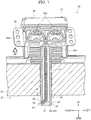
- FIG. 7 is a rear sectional view schematically showing the hinge unit 36 (the state in which the document cover is opened.). It is noted that the following explanation will be made on a basis of a condition in which the document cover 33 (the automatic document feeder 5) is closed.
- the pair of hinge units 36 supports the document cover 33 openably with respect to the platen glass 21.
- the pair of hinge units 36 is disposed separately from each other along one side on a rear side of a back (undersurface) of the cover frame 34. It is noted that because the pair of hinge units 36 has a same structure, respectively, the following explanation will be made by noticing on one hinge unit 36.
- the hinge unit 36 includes a support member 37, a mount member 38, and a detachment restricting mechanism 39.
- the support member 37 supports the document cover 33.
- the mount member 38 is linked turnably with the support member 37.
- the detachment restricting mechanism 39 includes a wire 51 whose upper end part (one end part) is connected with the support member 37 and whose lower end part (other end part) includes an engage part 53 (refer to FIGs. 4 and 5 ).
- the support member 37 is integrally formed while including a fitting part 40, a pair of right and left bearing plates 41, a top plate 42, a rotating shaft 43, and a pair of right and left flange parts 44.
- the fitting part 40 is formed substantially into a shape of a rectangular box.
- the pair of right and left bearing plates 41 and the top board 42 is formed at a rear part of the fitting part 40.
- the rotating shaft 43 is provided between the pair of bearing plates 41.
- the pair of right and left flange parts 44 projects outwardly from a lower part of the fitting part 40 and each bearing plate 41.
- the fitting part 40 is formed to be hollow.
- the fitting part 40 includes an assist mechanism 45 built therein and configured to assist an opening/closing operation of the document cover 33 (the automatic document feeder 5).
- the assist mechanism 45 includes a pair of right and left assist springs 45a, a spring support part 45b and an assist cam 45c.
- a front edge surface of each of the pair of right and left assist springs 45a (so-called coil springs) abuts against a front inner surface of the fitting part 40.
- the spring support part 45b supports each assist spring 45a.
- the assist cam 45C abuts against a rear end surface of the spring support part 45b.
- the assist mechanism 45 assists the opening operation of the document cover 33 (the automatic document feeder 5) by utilizing a force stretching each compressed assist spring 45a (refer to FIG. 6 ).
- the pair of bearing plates 41 is formed as a same plane with both right and left side surfaces of the fitting part 40 and extends rearward from a rear end of the fitting part 40, respectively.
- the pair of bearing plates 41 is disposed horizontally so as to face with each other.
- a shaft fixing part 41a which is a semi-circular plate when seen from a side is provided on an upper part of a rear end of each shaft supporting plate 41.
- a bearing hole 41b is formed so as to penetrate in the horizontal direction through each shaft fixing part 41a.
- a top board 42 is formed on a same plane with an upper face of the fitting part 40. The top board 42 extends across the pair of bearing plates 41.
- a rotating shaft 43 is formed into a cylindrical shape.
- the rotating shaft 43 is inserted through shaft supporting holes 41b of the rotating shaft 43.
- the rotating shaft 43 becomes a turning axis for the mount member 38 to turn with respect to the support member 37.
- the pair of flanges 44 extends respectively outwardly from lower positions of right and left outer side surfaces of the fitting part 40 and each bearing plates 41.
- Each flange 44 has three fastening holes 44a formed and arrayed in the front-rear direction.
- the mount member 38 includes a bearing part 46 and a leg part 47.
- the bearing part 46 is provided integrally with an assist cam 45c.
- the leg part 47 extends downward from the bearing part 46.
- the assist cam 45c described above is provided in the bearing part 46 such that the assist cam 45c protrudes forward.
- the assist cam 45c has a bearing hole 46a so as to penetrate in the horizontal direction thereof.
- the rotating shaft 43 described above is inserted through the bearing hole 46a. That is, the rotating shaft 43 is journaled by each shaft bearing hole 41b and the bearing hole 46a.
- the support member 37 is supported turnably with respect to the mount member 38 through the rotating shaft 43.
- An insertion restricting part 48 protruding to the outside in the front-rear and right and left directions is formed at a lower part of the bearing part 46. It is noted that a projection projecting downward is formed on a lower face of the insertion restricting part 48.
- the leg part 47 is formed substantially into a hollow square pillar shape.
- a tapered face 47a chamfered slant is formed at a rear side of a lower part of the leg part 47.
- a substantially rectangular wire opening 50 is formed so as to penetrate through a right side face of the lower part of the leg part 47. It is noted that the shape of the wire opening part 50 is arbitrary and the position where the wire opening part 50 is formed through is also arbitrary. For instance, the wire opening part 50 may be formed through a left side surface or at a front or rear surface.
- the detachment restricting mechanism 39 includes a wire 51 and a wire guide 52.
- the wire 51 i.e., an engage movable member, has flexibility.
- the wire 51 moves in linkage with a turn of the support member 37 involved in opening/closing operation of the document cover 33.
- the wire guide 52 is provided in the mount member 38. The wire guide 52 guides the move of the wire 51.
- the wire 51 is formed by twisting a plurality of metallic wire rods together. An upper end (one end) of the wire 51 is connected to a wire fixing part 42a provided on a back face (lower face) of the top board 42 of the support member 37. Still further, as shown in FIG. 5 , an engage part 53 which is capable of going in and out of a wire opening part 50 is formed at a lower end (other end) of the wire 51. As shown in FIG. 4 , in a case where an angle formed between the support member 37 and the mount member 38 is substantially 90° (an angle corresponding a state in which the document cover 33 (the automatic document feeder 5) is closed), the engage part 53 protrudes out of the wire opening part 50 (refer to FIG. 5 ). That is, the wire 51 is set to have a length such that the engage part 53 protrudes out of the wire opening part 50 through a passage specified by the wire guide 52 in a state in which the document cover 33 is closed.
- the wire guide 52 includes a wire tube 54 and a path changing part 55.
- the wire 51 is inserted through the wire tube 54.
- the path changing part 55 directs the upper end of the wire 51 rearward at an upper part of the wire tube 54.
- the wire tube 54 is formed into a hollow rectangular cylinder shape.
- the wire tube 54 extends in the vertical direction across the bearing part 46 and the leg part 47.
- the wire tube 54 is formed integrally at a center in the horizontal direction of an inner face of a front side of the bearing part 46 and the leg part 47.
- a lower end of the wire tube 54 is connected to the wire opening part 50 (refer to FIG. 5 ).
- An upper end of the wire tube 54 is located substantially at a same level with a shaft center of the rotating shaft 43.
- the wire tube 54 communicates inside and outside of the mount member 38 through the wire opening part 50.
- the path changing part 55 is provided at a center part in the horizontal direction of the support member 37.
- the path changing part 55 is disposed and fixed at a upper front part of the bearing hole 46a. It is noted that the assist cam 45c is not shown in FIG. 4 .
- the path changing part 55 has a changing part body 55a and a facing part 55b.
- the changing part body 55a is formed substantially into a shape of a fan when viewed from a side.
- the facing part 55b is disposed so as to face the changing part body 55a at an upper front side of the changing part body 55a with a gap therebetween.
- the wire 51 extending from the upper end of the wire tube 54 is in sliding contact with a circumferential face of the changing part body 55a.
- a pair of right and left fitting mount portions 56 is formed in the cover frame 34 of the document cover 33.
- the pair of right and left fitting mount portions 56 corresponds to positions where each hinge unit 36 is mounted.
- each of the fitting mount portions 56 is concavely provided at a rear side of the back face (under face) of the cover frame 34 at the lower side of the conveying mechanism 31 and a lower side of the discharge tray 32.
- Each of the fitting mount portions 56 is formed into a shape and size into which the support member 37 of the hinge unit 36 can fit.
- a plurality (three) of screw holes not shown are formed respectively near right and left edge portions of the mount part 56.
- the support member 37 of the hinge unit 36 is fitted into the mount part 56.
- a screw not shown is inserted through each fastening hole 44a formed at each flange 44 of each support member 37. The screw is fastened into each screw hole of the mount part 56. Thereby, the hinge unit 36 is mounted to the document cover 33.
- a pair of right and left insert mount portions 57 is formed through the upper plate 2a of the apparatus body 2.
- the pair of right and left insert mount portions 57 corresponds to positions where the hinge units 36 are mounted.
- the insert mount part 57 is formed so as to penetrate through in the vertical direction on a back face side of the upper plate 2a composing an upper face of the apparatus body 2.
- the insert mount part 57 is formed into a shape and size into which the leg part 47 of the mount member 38 can fit.
- An internal space S1 of the apparatus body 2 is formed under the upper plate 2a.
- the leg part 47 penetrates through the insert mount part 57.
- a lower end of the leg part 47 is located in the internal space S1.
- each hinge unit 36 is mounted to the apparatus body 2 . It is noted that a state in which each hinge unit 36 is mounted to the document cover 33 is assumed. The following explanation will be made by noticing on one hinge unit 36.
- the angle formed between the support member 37 of the hinge unit 36 and the mount member 38 is set to be greater than 90° at first as shown in FIGs. 6 and 7 .
- the angle formed between the support member 37 and the mount member 38 is set substantially at 150° (an angle formed between a horizontal face and the support member 37 is about 60°). That is, in a case where the automatic document feeder 5 is mounted to the apparatus body 2 through the hinge unit 36, the hinge unit 36 is turned such that the document cover 33 (the automatic document feeder 5) is opened.
- the wire 51 whose one end is fixed to the support member 37 is wrapped around the circumferential face of the changing part body 55a and is stretched downward such that the wire 51 makes a U-turn (refer to FIG. 6 ). That is, the lower end (other end) of the wire 51 is moved upward by being guided by the wire guide 52. Thereby, the engage part 53 formed at the lower end of the wire 51 enters the inside of the wire opening part 50 (refer to FIG. 7 ). It is noted that in the following explanation, the position where the engage part 53 enters the inside of the wire opening part 50 will be referred to as a 'release position P1' hereinafter.
- the leg part 47 of the hinge unit 36 (the mount member 38) is inserted through the insert mount part 57.
- the insertion restricting part 48 of the mount member 38 abuts against an upper face (upper end edge of the insert mount part 57) of the apparatus body 2 (the upper plate 2a) and then, the insertion of the leg part 47 to the insert mount part 57 is stopped (refer to FIG. 6 ).
- the hinge unit 36 is mounted to the apparatus body 2.
- the edge (lower end) of the leg part 47 penetrates the insert mount part 57 and protrudes into the internal space S1.
- the wire opening part 50 formed in the leg part 47 is located at a lower position distant from a lower face of the upper plate 2a by a distance D (refer to FIG. 5 ).
- the automatic document feeder 5 (the document cover 33) is permitted to move upward by the distance D from the platen glass 21 and others (the upper face of the upper plate 2a), a space between the platen glass 21 and the mat 35 of the document cover 33 is separated by the distance D.
- This arrangement makes it possible to press a thick document such as a book stably on the platen glass 21 for example.
- the distance D is arbitrarily set by considering a maximum thickness of a document whose images are to be read.
- the document cover 33 (the automatic document feeder 5) is opened at first as shown in FIGs. 6 and 7 .
- the engage part 53 moves to the release position P1 by setting the angle formed between the support member 37 and the mount member 38 at about 150° as described above.
- the operator lifts up the automatic document feeder 5 in this state. Because the engage part 53 is embedded within the wire opening part 50, the engage part 53 will not contact with the engaged part 58 (the under face of the upper plate 2a). Thereby, the leg part 47 can be pulled out of the insert mount part 57. That is, the automatic document feeder 5 can be removed out of the apparatus body 2.
- the detachment restricting mechanism 39 restricts the mount member 38 from being detached from the apparatus body 2 by moving the engage part 53 to the engage position P2 where the engage part 53 can abut against the engaged part 58 formed on the apparatus body 2 when the document cover 33 is closed.
- the detachment restricting mechanism 39 enables the mount member 38 to be detached from the apparatus body 2 by moving the engage part 53 to the release position P1 where the engage part 53 is unable to abut against the engaged part 58 when the document cover 33 is opened.
- the detachment of the mount member 38 from the apparatus body 2 is restricted in the state in which the document cover 33 is closed and the document S is pressed to the platen glass 21, i.e., in the state in which the document cover 33 is used. Meanwhile, in the state in which the document cover 33 is opened, i.e., the state in which the document cover 33 is not used, the mount member 38 can be detached from the apparatus body 2.
- the mount member 38 can be detached from the apparatus body 2.
- This arrangement makes it possible to carry out the work for removing the document cover 33 (the automatic document feeder 5) readily and swiftly in maintenance works for example.
- the hinge unit 36 of the first embodiment is configured such that the wire 51 moves between the engage position P2 and the release position P1 by being guided by the wire guide 52.
- the engagement movable member is the wire 51 having flexibility, it is possible to move the wire 51 by deforming into various shapes depending on the wire guide 52 in a desired path. This arrangement makes it possible to readily draw and dispose the wire 51 even if an enough internal space cannot be assured within the support member 37 and the mount member 38.
- This configuration is specially effective in a case where the assist mechanism 45 is built in the support member 37 and an internal space of the support member 37 is limited.
- the pair of hinge units 36 of the first embodiment is provided horizontally to the cover frame 34 (or the upper plate 2a of the apparatus body 2), a number of the hinge units 36 to be disposed is arbitrary.
- the hinge unit 36 may be provided only at one place where weight balances.
- the hinge unit 36 of the first embodiment may be used as one of the pair of right and left hinge units, and another hinge unit in which the detachment restricting mechanism 39 is omitted may be used as another hinge unit.
- FIG. 8 is a perspective view showing the hinge unit 60.
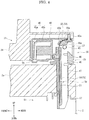
- FIG. 9 is a side sectional view schematically showing the hinge unit 60 (a state in which a document cover is closed).
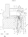
- FIG. 10 is a side sectional view schematically showing the hinge unit 60 (a state in which the document cover is opened). It is noted that the same or corresponding components with the hinge unit 36 of the first embodiment will be denoted by the same reference numerals and their explanation will be omitted here.
- a configuration of the detachment restricting mechanism 61 is mainly different from the hinge unit 36 of the first embodiment in a hinge unit 60 of the second embodiment. Still further, the top board 42 of the support member 37 and the assist mechanism 45 built in the support member 37 (the fitting part 40) is omitted in the hinge unit 60 of the second embodiment. It is noted that an upper part of the bearing part 46 of the mount member 38 projects out of an upper face of the support member 37.
- the fitting part 40 of the hinge unit 60 of the second embodiment has a partition plate 62 vertically dividing the inside thereof and a rib 63 horizontally dividing the inside thereof.
- An engage plate 64 is formed on a rear face of the fitting part 40 (refer to FIG. 9 ). The engage plate 64 projects rearward from a lower right side of the fitting part 40. A first engage hole not shown penetrates through the engage plate 64.
- the rotating shaft part 68 includes a pair of circumferential parts 68a and a pair of plane parts 68b.
- the pair of circumferential parts 68a is formed of a circumferential surface of column.
- the pair of plane parts 68b is formed flatly at a position facing to the column circumferential surface. It is noted that a minimum outer diameter of the rotating shaft part 68 formed of the pair of plane parts 68b is set to be slightly smaller than a width of a bearing groove part 49a of the mount member 38.
- the mount member 38 of the hinge unit 60 includes a bearing part 49 and a leg part 47.
- the bearing part 49 is formed into a shape of hook when seen from a side.
- the leg part 47 extends downward from the bearing part 49.
- the bearing part 49 includes the bearing groove part 49a and a bearing body 49b.
- the bearing groove part 49a is formed such that the bearing groove part 49a is cut front obliquely upward from a lower rear face of a substantially rectangular parallelepiped.
- the bearing body 49b is formed at an upper end of the bearing groove part 49a.
- the bearing body 49b forms a substantially columnar space extending in the horizontal direction.
- the bearing groove part 49a is formed such that the bearing groove part 49a opens the substantially columnar space of the bearing body 49b.
- a procedure for assembling the hinge unit 60 will be explained.
- the operator advances each plane part 68b of the rotating shaft part 68 while being in sliding contact with the bearing groove part 49a of the bearing part 49.
- one circumferential part 68a of the rotating shaft part 68 abuts against an inner circumferential face of the bearing body 49b.
- each plane part 68b of the rotating shaft part 68 shifts in the circumferential direction, so that the bearing groove part 49a is restricted from slipping out.
- the support member 37 is turnably linked to the mount member 38 without detaching from the mount member 38.
- the detachment restricting mechanism 61 of the hinge unit 60 includes an engage movable member 65 and a hook guide 66.
- the engage movable member 65 is formed into a shape lengthy in the vertical direction by a resin material.
- the engage movable member 65 moves such that it draws substantially a circular arc between the engage position P2 and the release position P1.
- the hook guide 66 is provided in the mount member 38. The hook guide 66 guides the move of the engage movable member 65.
- the engage movable member 65 is provided within the sliding space S2 formed in the leg part 47 of the mount member 38.
- the sliding space S2 is formed at a right inner side from the leg part 47 to the bearing part 46.
- a right side surface of the sliding space S2 is substantially opened to the outside.
- a hook opening 67 communicating with the sliding space S2 is formed at a lower side of the leg part 47.
- the hook opening 67 is formed into a rectangular shape when seen a front side.
- the hook opening 67 extends from the lower end of the leg part 47 substantially to a center in the vertical direction.
- the engage movable member 65 is formed integrally by a vertical part 70 and a bend part 71, an extension part 72.
- the vertical part 70 is formed substantially into a shape of a plate.
- the bend part 71 is formed substantially into a shape of a plate slightly bending forward from a lower end of the vertical part 70.
- the extension part 72 extends downward from the lower end of the bend part 71. That is, the engage movable member 65 is formed so as to bend such that the engage movable member 65 slightly projects rearward as a whole.
- the vertical part 70a is formed so as to penetrate through an upper end part of the vertical part 70.
- a lower end portion of a coil spring 73 i.e., an elastic member, is turnably engaged with the vertical part 70a.
- An upper end part of the coil spring 73 is turnably engaged with a first engage hole opening to an engage plate 64 of the fitting part 40. Accordingly, the coil spring 73 is provided at the upper end part (one end part) of the engage movable member 65. That is, the engage movable member 65 is rotatably connected to the support member 37 through the coil spring 73.
- the extension part 72 is formed widely by projecting in the left direction more than the vertical part 70 and the bend part 71 (refer to FIG. 8 ).
- a hooked engage part 74 bending forward substantially at right angles is formed at the lower end part of the extension part 72.
- the engage part 74 goes in/out of the hook opening 67.
- the hook guide 66 guides a sliding move of the engage movable member 65 within the sliding space S2.
- the hook guide 66 is constructed as a wall face on a back face composing the sliding space S2.
- the hook guide 66 includes a vertical guide 80, a convex guide 81, an upper side inclination guide 82, a lower side inclination guide 84, and a plurality of fall preventing pieces 85.
- the convex guide 81 is provided under the vertical guide 80.
- the upper side inclination guide 82 extends downward while slightly inclining forward from the lower side of the convex guide 81.
- the lower side inclination guide 84 extends downward while slightly inclining forward from the lower end of the upper side inclination guide 82 through a stepped part 83.
- the plurality of fall preventing pieces 85 is formed substantially into a rectangular shape when seen from a side so as to cover a right surface of the sliding space S2.
- the vertical part 70 and the bend part 71 of the engage movable member 65 come into sliding contact with the vertical guide 80.
- the bend part 71 comes in sliding contact with the convex guide 81.
- the extension part 72 comes in sliding contact with the upper side inclination guide 82, the stepped part 83 and the lower side inclination guide 84. It is noted that the stepped part 83 extends downward while inclining slightly forward.
- the plurality of fall preventing pieces 85 are disposed respectively an upper side of the hook opening 67, an upper side of the convex guide 81, an upper part of the upper side inclination guide 82, and the stepped part 83. Each fall preventing pieces 85 prevents the engage movable member 65 from falling out of the sliding space S2.
- the engage part 74 of the engage movable member 65 projects to the outside from the hook opening 67. That is, the engage part 74 faces to the engage position P2.
- the vertical part 70 of the engage movable member 65 rotatably connected to the support member 37 is pulled toward front obliquely upper side.
- the entire engagement movable member 65 is moved upward by being guided by the hook guide 66.
- the lower end part of the extension part 72 of the engage movable member 65 slides sequentially on the lower side inclination guide 84, the stepped part 83 and the upper side inclination guide 82.
- the engage part 74 moves upward while substantially drawing an oval orbit convex rearward when seen from a side.
- the engage part 74 of the engage movable member 65 enters the inside of the hook opening 67. That is, the engage part 74 is located at the release position P1.
- the back face at the lower end part of the extension part 72 slides on the upper side inclination guide 82 and abuts against the stepped part 83 when the engage part 74 is moved from the release position P1 to the engage position P2 (in closing the document cover 33).
- the lower end part of the extension part 72 is guided on the stepped part 83 and moves forward. In succession, the lower end part of the extension part 72 is guided to the hook opening 67 by the lower side inclination guide 84.
- each hinge unit 60 of the second embodiment will be explained with reference to FIGs. 9 and 10 .
- the leg part 47 moves upward by the distance D (refer to FIG. 9 ) similarly to the hinge unit 36 of the first embodiment.
- the engage part 74 located at the engage position P2 abuts against the engaged part 58.
- the pullout of the leg part 47 from the insert mount part 57 is restricted and the detachment of the automatic document feeder 5 out of the apparatus body 2 is prohibited.
- the automatic document feeder 5 (the document cover 33) is opened and the engage part 74 is moved to the release position P1 as shown in FIG. 10 . It is noted that the engage part 74 moves to the release position P1 when a maximum opening angle of each hinge unit 60, e.g., an angle formed between the horizontal surface and the support member 37 is about 60°. In this state, the operator lifts up the automatic document feeder 5. Because the engage part 74 does not contact with the engaged part 58, the leg part 47 can be smoothly pulled out of the insert mount part 57. That is, the automatic document feeder 5 can be removed out of the apparatus body 2.
- the hinge unit 60 of the second embodiment described above makes it possible to move the engage movable member 65 reliably between the engage position P2 and the release position P1. Still further, because the engage part 74 is formed into a shape of hook, it is possible to adequately maintain a state in which the engage part 74 is hooked by the engaged part 58. This arrangement makes it possible to assure the restriction of the detachment of the mount member 38 from the apparatus body 2 in using the automatic document feeder 5 (the document cover 33).
- the hinge unit 60 of the second embodiment is configured such that the engage part 74 goes in and out in the front and rear direction
- the present disclosure is not limited that.
- the direction in which the engage part 74 goes in and out is arbitrary and the hinge unit 60 may be configured such that the engage part 74 goes in and out in the horizontal direction from either one side face of right and left side surfaces. In this case, the position where the hook opening 67 is formed is changed in accordance to the in and out direction of the engage part 74.
- the coil spring 73 is used as the elastic member in the hinge unit 60 of the second embodiment, a linearly formed and stretchable rubber may be used for example instead of the coil spring 73.
- the present disclosure is not limited to that.
- the coil spring 73 may be omitted and the support member 37 may be connected with the engage movable member 65 directly in a turnable state not shown.
- the hinge units 60 of the second embodiment are provided as a right and left pair to the cover frame 34 (or the upper plate 2a of the apparatus body 2), a number of the hinge units 36 to be disposed is arbitrary. Still further, it is preferable to use the hinge units 60 of the second embodiment (including the modified example) as at least either one among the pair of hinge units. For instance, it is preferable to use the hinge unit 36 attached with the assist mechanism 45 at a lower side of the conveying mechanism 31 and to use the hinge unit 60 from which the assist mechanism 45 is omitted to a lower side of the discharge tray 32 in the automatic document feeder 5 of a small multi-function printer and others.
- the hinge unit 36 supports a heavy part and the hinge unit 60 supports a light part. This arrangement makes it possible to adequately assist an opening/closing operation of the document cover 33. It is noted that in this case, the detachment restricting mechanism 39 of the hinge unit 36 may be omitted.
- the present disclosure is not limited to that.
- the configuration of the present disclosure is applicable to other image forming apparatuses such as a copier and a printer and other image reading apparatuses such as a scanner.
- the present disclosure may be configured such that the automatic document feeder 5 is omitted for example.
Landscapes
- Engineering & Computer Science (AREA)
- Multimedia (AREA)
- Signal Processing (AREA)
- Holders For Sensitive Materials And Originals (AREA)
- Electrophotography Configuration And Component (AREA)
- Exposure Or Original Feeding In Electrophotography (AREA)
- Facsimiles In General (AREA)
- Facsimile Scanning Arrangements (AREA)
Claims (8)
- Gelenkeinheit (36, 60) umfassend:ein Stützelement (37), das konfiguriert ist, eine Dokumentpresse (33) zu stützen, die ein Dokument (S) an eine Dokumentplatzierungsfläche (21) presst, die auf einem Gehäuse (2) eines Gerätekörpers bereitgestellt ist, wobei die Dokumentpresse (33) in Bezug auf die Dokumentplatzierungsfläche (21) geöffnet und geschlossen werden kann;ein Befestigungselement (38), das drehbar mit dem Stützelement (37) gekoppelt ist und abnehmbar an dem Gehäuse (2) befestigt ist; undein Abtrennungseinschränkungselement (39, 61), dessen eines Endteil mit dem Stützelement (37) verbunden ist und das ein bewegliches Eingriffselement (51, 65) beinhaltet, das ein Eingriffsteil (53, 74) an einem anderen Ende davon bildet;wobei sich das bewegliche Eingriffselement (51, 65), welches mit dem Stützelement (37) verbunden ist, gekoppelt mit einer Drehung des Stützelements (37) bewegt, die mit einem Öffnungs- und einem Schließvorgang der Dokumentpresse (33) einhergeht;wobei das Abtrennungseinschränkungselement (39, 61) das Befestigungselement (38) einschränkt von dem Gehäuse (2) abgetrennt zu werden, durch Bewegen des Eingriffsteils (53, 74) in eine Eingriffsposition (P2), in welcher das Eingriffsteil (53, 74) an einem an dem Gehäuse (2) gebildeten Eingreifteil (58) anliegen kann, in einem Fall, in welchem die Dokumentpresse (33) geschlossen ist, und dem Befestigungselement (38) ermöglicht, sich von dem Gehäuse (2) zu trennen, durch Bewegen des Eingriffsteils (53, 74) in eine Freigabeposition (P1), in welcher das Eingriffsteil (53, 74) nicht an dem Eingreifteil (58) anliegen kann, in einem Fall, in welchem die Dokumentpresse (33) geöffnet ist.
- Gelenkeinheit (36) gemäß Anspruch 1, wobei das bewegliche Eingriffselement aus einem flexiblen Draht (51) gebildet ist; und
wobei das Abtrennungseinschränkungselement (39) weiterhin eine Drahtführung (52) beinhaltet, die in dem Befestigungselement (38) bereitgestellt ist und den Draht (51) führt, der sich zwischen der Eingriffsposition (P2) und der Freigabeposition (P1) bewegt. - Gelenkeinheit (60) gemäß Anspruch 1, wobei das bewegliche Eingriffselement (65) weiterhin ein drehbar mit dem Stützelement (37) verbundenes Endteil und das hakenförmige Eingriffsteil (74) an dem anderen Endteil beinhaltet;
wobei das Abtrennungseinschränkungselement (61) weiterhin eine Hakenführung (66) beinhaltet, die in dem Befestigungselement (38) bereitgestellt ist und das bewegliche Eingriffselement (65) führt, das sich zwischen der Eingriffsposition (P2) und der Freigabeposition (P1) bewegt. - Gelenkeinheit (60) gemäß Anspruch 3, wobei ein elastisches Element (73) an dem einen Ende des beweglichen Eingriffselements (65) bereitgestellt ist.
- Gelenkeinheit (60) gemäß Anspruch 3 oder 4, wobei das bewegliche Eingriffselement (65) biegbar gebildet ist und sich bewegt, um einen kreisförmigen Bogen zwischen der Eingriffsposition (P2) und der Freigabeposition (P1) zu ziehen.
- Gelenkeinheit (36, 60) gemäß einem der Ansprüche 1 bis 5, wobei ein Abstand (D) zwischen dem Eingriffsteil (53, 74) und dem Eingreifteil (58) eine maximale Dicke eines Dokuments (S) ist, dessen Bilder eingelesen werden sollen.
- Bildeinlesegerät (4) umfassend:eine Gelenkeinheit (36, 60) gemäß einem der Ansprüche 1 bis 6.
- Bilderzeugungsgerät (3) umfassend:eine Gelenkeinheit (36, 60) gemäß einem der Ansprüche 1 bis 6.
Applications Claiming Priority (1)
| Application Number | Priority Date | Filing Date | Title |
|---|---|---|---|
| JP2013144687A JP5873845B2 (ja) | 2013-07-10 | 2013-07-10 | ヒンジ構造およびこれを備えた画像読取装置並びに画像形成装置 |
Publications (3)
| Publication Number | Publication Date |
|---|---|
| EP2824906A2 EP2824906A2 (de) | 2015-01-14 |
| EP2824906A3 EP2824906A3 (de) | 2015-07-15 |
| EP2824906B1 true EP2824906B1 (de) | 2017-09-13 |
Family
ID=50933003
Family Applications (1)
| Application Number | Title | Priority Date | Filing Date |
|---|---|---|---|
| EP14171905.4A Not-in-force EP2824906B1 (de) | 2013-07-10 | 2014-06-11 | Scharniereinheit und Bildlesevorrichtung und Bilderzeugungsvorrichtung damit |
Country Status (4)
| Country | Link |
|---|---|
| US (1) | US9203995B2 (de) |
| EP (1) | EP2824906B1 (de) |
| JP (1) | JP5873845B2 (de) |
| CN (1) | CN104284044B (de) |
Families Citing this family (14)
| Publication number | Priority date | Publication date | Assignee | Title |
|---|---|---|---|---|
| JP6222473B2 (ja) * | 2014-08-29 | 2017-11-01 | 京セラドキュメントソリューションズ株式会社 | 画像読取装置及び該画像読取装置を備えた画像形成装置 |
| JP6379882B2 (ja) | 2014-09-03 | 2018-08-29 | ブラザー工業株式会社 | 読取装置 |
| JP6184392B2 (ja) * | 2014-11-08 | 2017-08-23 | キヤノン株式会社 | 画像読取装置及び画像形成装置 |
| JP6311638B2 (ja) * | 2015-04-07 | 2018-04-18 | 京セラドキュメントソリューションズ株式会社 | ヒンジ構造及びこれを備えた画像形成装置 |
| JP6554885B2 (ja) * | 2015-04-14 | 2019-08-07 | 富士ゼロックス株式会社 | 画像読取り装置および画像形成装置 |
| JP6328083B2 (ja) * | 2015-09-07 | 2018-05-23 | キヤノン株式会社 | 画像読取装置及び画像形成装置 |
| JP6582884B2 (ja) * | 2015-10-30 | 2019-10-02 | ブラザー工業株式会社 | 複合機 |
| JP6579321B2 (ja) * | 2015-12-01 | 2019-09-25 | セイコーエプソン株式会社 | 画像読取装置 |
| JP6658634B2 (ja) * | 2017-03-16 | 2020-03-04 | 京セラドキュメントソリューションズ株式会社 | 原稿押さえユニット、およびこれを備えた自動原稿搬送装置、画像形成装置 |
| JP6838449B2 (ja) * | 2017-03-23 | 2021-03-03 | セイコーエプソン株式会社 | 原稿読取装置 |
| US10855862B2 (en) * | 2017-11-15 | 2020-12-01 | Kyocera Document Solutions Inc. | Reading device and image forming apparatus |
| TWM561370U (zh) * | 2017-12-28 | 2018-06-01 | 崴強科技股份有限公司 | 轉軸裝置 |
| JP7027881B2 (ja) * | 2017-12-28 | 2022-03-02 | 京セラドキュメントソリューションズ株式会社 | ヒンジ機構、及び画像形成装置 |
| USD975177S1 (en) | 2020-02-27 | 2023-01-10 | Hewlett-Packard Development Company, L.P. | Printer stand legs |
Family Cites Families (40)
| Publication number | Priority date | Publication date | Assignee | Title |
|---|---|---|---|---|
| US4691584A (en) * | 1985-02-20 | 1987-09-08 | Ohi Seisakusho Co., Ltd. | Actuator for remote devices or the like |
| JP3153422B2 (ja) * | 1994-10-07 | 2001-04-09 | 象印マホービン株式会社 | コンテナのヒンジ装置 |
| US6427500B1 (en) * | 1998-11-09 | 2002-08-06 | The Eastern Company | Latch, lock and hinge system for use with closures such as tonneau covers |
| TW536076U (en) * | 1999-07-28 | 2003-06-01 | Benq Corp | Lid lifting and axle rotating mechanism of scanner |
| JP2002031862A (ja) * | 2000-07-14 | 2002-01-31 | Riso Kagaku Corp | 原稿読み取り装置及びこれを用いた印刷装置 |
| US6351624B1 (en) * | 2000-07-28 | 2002-02-26 | Toshiba Tec Kabushiki Kaisha | Document hold-down device and method for holding down document |
| TW534547U (en) * | 2001-02-23 | 2003-05-21 | Avision Inc | Adjustable document cover height for scanner |
| US20020164197A1 (en) * | 2001-04-06 | 2002-11-07 | Lee Ta Yi | Pivotal connector for scanner |
| KR100474425B1 (ko) * | 2003-04-30 | 2005-03-10 | 삼성전자주식회사 | 사무기기의 커버 개폐용 힌지장치 |
| TWM251736U (en) * | 2004-02-03 | 2004-12-01 | Benq Corp | Business machine |
| JP2005338479A (ja) * | 2004-05-27 | 2005-12-08 | Canon Inc | ヒンジ機構及びこれを用いた画像読取装置 |
| TWI248756B (en) * | 2004-12-14 | 2006-02-01 | Benq Corp | Scanner capable of pressing a scanning document |
| US7418766B2 (en) * | 2004-12-22 | 2008-09-02 | Xerox Corporation | Hinge with tandem pivot structure motion lock and override |
| JP3962746B2 (ja) * | 2004-12-28 | 2007-08-22 | キヤノン株式会社 | 画像読取装置 |
| KR100676814B1 (ko) * | 2005-04-04 | 2007-02-01 | 삼성전자주식회사 | 복합기 |
| TWI268095B (en) * | 2005-06-02 | 2006-12-01 | Benq Corp | Scanner |
| JP4713276B2 (ja) * | 2005-08-29 | 2011-06-29 | リコープリンティングシステムズ株式会社 | 画像形成装置 |
| US8237995B2 (en) * | 2006-02-22 | 2012-08-07 | Oki Data Corporation | Multifunction apparatus |
| JP4306686B2 (ja) * | 2006-02-27 | 2009-08-05 | ブラザー工業株式会社 | 画像読取装置 |
| DE102006012062B4 (de) * | 2006-03-16 | 2017-05-04 | Audi Ag | Schließeinrichtung für einen Deckel eines Kraftwagens |
| US7894748B2 (en) * | 2006-12-28 | 2011-02-22 | Lite-On Technology Corporation | Multi-function printer with a locking device and operational method thereof |
| EP1958537B1 (de) * | 2007-02-19 | 2014-04-30 | Pro-Cord S.p.A. | Ineinanderpassender und -faltender Tisch |
| JP4898538B2 (ja) | 2007-04-19 | 2012-03-14 | 加藤電機株式会社 | 原稿圧着板開閉装置及び原稿圧着板を備えた事務機器 |
| JP4573061B2 (ja) * | 2008-07-18 | 2010-11-04 | ブラザー工業株式会社 | カバー体の開閉装置、それを備えた画像読取装置さらに画像読取装置を備えた画像記録装置 |
| JP5183378B2 (ja) * | 2008-09-09 | 2013-04-17 | 京セラドキュメントソリューションズ株式会社 | 原稿送り装置の取付構造及びこれを搭載した画像形成装置 |
| JP2010093390A (ja) * | 2008-10-03 | 2010-04-22 | Oki Data Corp | 画像形成装置 |
| JP5441097B2 (ja) * | 2008-12-09 | 2014-03-12 | 株式会社ナチュラレーザ・ワン | 原稿圧着板開閉装置並びに事務機器 |
| JP5569925B2 (ja) * | 2009-08-20 | 2014-08-13 | 株式会社ナチュラレーザ・ワン | 開閉装置の抜け防止機構並びにこの抜け防止機構を備えた事務機器 |
| JP5293536B2 (ja) * | 2009-09-28 | 2013-09-18 | ブラザー工業株式会社 | 画像記録装置 |
| JP5293538B2 (ja) * | 2009-09-28 | 2013-09-18 | ブラザー工業株式会社 | 画像記録装置 |
| JP5100763B2 (ja) * | 2010-01-19 | 2012-12-19 | シャープ株式会社 | 原稿読取装置及びこれを備えた画像形成装置 |
| US8675262B2 (en) * | 2010-03-25 | 2014-03-18 | Kyocera Document Solutions Inc. | Image reading device and image forming apparatus including the same |
| CN201672482U (zh) * | 2010-05-17 | 2010-12-15 | 苏州达方电子有限公司 | 台灯及内藏连结组件的台灯悬臂结构 |
| DE102010056413B4 (de) * | 2010-12-23 | 2022-03-10 | Volkswagen Aktiengesellschaft | Schließsystem zur Notentriegelung eines Kofferraumes, insbesondere eines frontseitigen Kofferraumes |
| JP5596002B2 (ja) * | 2011-11-16 | 2014-09-24 | 京セラドキュメントソリューションズ株式会社 | 原稿カバー、およびこれを備えた画像読取装置、画像形成装置 |
| JP6047958B2 (ja) * | 2012-07-06 | 2016-12-21 | ブラザー工業株式会社 | 画像処理装置 |
| TWI514111B (zh) * | 2012-07-18 | 2015-12-21 | Kinpo Elect Inc | 鎖固元件、蓋體裝置及多功能事務機 |
| JP6031864B2 (ja) * | 2012-07-20 | 2016-11-24 | ブラザー工業株式会社 | 画像読取装置 |
| US9065946B2 (en) * | 2013-05-31 | 2015-06-23 | Kyocera Document Solutions Inc. | Image forming apparatus |
| US9100521B2 (en) * | 2013-06-13 | 2015-08-04 | Canon Kabushiki Kaisha | Image reading apparatus and image forming apparatus |
-
2013
- 2013-07-10 JP JP2013144687A patent/JP5873845B2/ja not_active Expired - Fee Related
-
2014
- 2014-05-26 CN CN201410225262.8A patent/CN104284044B/zh not_active Expired - Fee Related
- 2014-06-11 EP EP14171905.4A patent/EP2824906B1/de not_active Not-in-force
- 2014-06-13 US US14/303,750 patent/US9203995B2/en not_active Expired - Fee Related
Non-Patent Citations (1)
| Title |
|---|
| None * |
Also Published As
| Publication number | Publication date |
|---|---|
| JP2015018088A (ja) | 2015-01-29 |
| CN104284044B (zh) | 2017-10-24 |
| JP5873845B2 (ja) | 2016-03-01 |
| EP2824906A3 (de) | 2015-07-15 |
| EP2824906A2 (de) | 2015-01-14 |
| US9203995B2 (en) | 2015-12-01 |
| US20150015920A1 (en) | 2015-01-15 |
| CN104284044A (zh) | 2015-01-14 |
Similar Documents
| Publication | Publication Date | Title |
|---|---|---|
| EP2824906B1 (de) | Scharniereinheit und Bildlesevorrichtung und Bilderzeugungsvorrichtung damit | |
| US8194255B2 (en) | Image forming apparatus | |
| JP5873848B2 (ja) | シート給送装置及びそれを備えた画像形成装置 | |
| US8579282B2 (en) | Image forming apparatus | |
| US9134686B2 (en) | Image forming apparatus provided with movable conveying unit | |
| JP2011013429A (ja) | 画像形成装置 | |
| US20110211223A1 (en) | Image forming apparatus | |
| US9145274B2 (en) | Sheet storage cassette and image forming apparatus including same | |
| US9796545B2 (en) | Sheet conveying device and image forming apparatus including sheet conveying device | |
| US8238783B2 (en) | Multi-function printer | |
| US9169091B2 (en) | Sheet feeder and image forming apparatus provided with same | |
| US8625121B2 (en) | Image reading device and image forming apparatus | |
| KR101821616B1 (ko) | 화상형성장치 | |
| JP6016745B2 (ja) | 原稿押えの取付構造およびこれを備えた画像形成装置 | |
| US9169092B2 (en) | Sheet feeding device, image forming apparatus provided with the same, and image reading device provided with the same | |
| US20150001787A1 (en) | Sheet feed apparatus, and image forming apparatus and image reading apparatus including the sheet feed apparatus | |
| US8090290B2 (en) | Attachment structure of automatic document feeder, and image-reading device and image-forming apparatus including the same | |
| US20120099888A1 (en) | Image forming apparatus and opening/closing device | |
| JP5790324B2 (ja) | 画像読取装置および画像読取装置を備えた画像形成装置 | |
| JP5994014B2 (ja) | ヒンジ構造およびこれを備えた画像読取装置並びに画像形成装置 | |
| JP6597509B2 (ja) | シート供給装置およびこれを備える画像形成装置 | |
| JP2017095254A (ja) | シート搬送機能を有する装置、画像読取装置及び画像形成装置 | |
| JP5733081B2 (ja) | 画像形成装置 | |
| JP2013221952A (ja) | 画像形成装置 | |
| JP2001122478A (ja) | 画像形成装置 |
Legal Events
| Date | Code | Title | Description |
|---|---|---|---|
| 17P | Request for examination filed |
Effective date: 20140611 |
|
| AK | Designated contracting states |
Kind code of ref document: A2 Designated state(s): AL AT BE BG CH CY CZ DE DK EE ES FI FR GB GR HR HU IE IS IT LI LT LU LV MC MK MT NL NO PL PT RO RS SE SI SK SM TR |
|
| AX | Request for extension of the european patent |
Extension state: BA ME |
|
| PUAI | Public reference made under article 153(3) epc to a published international application that has entered the european phase |
Free format text: ORIGINAL CODE: 0009012 |
|
| PUAL | Search report despatched |
Free format text: ORIGINAL CODE: 0009013 |
|
| AK | Designated contracting states |
Kind code of ref document: A3 Designated state(s): AL AT BE BG CH CY CZ DE DK EE ES FI FR GB GR HR HU IE IS IT LI LT LU LV MC MK MT NL NO PL PT RO RS SE SI SK SM TR |
|
| AX | Request for extension of the european patent |
Extension state: BA ME |
|
| RIC1 | Information provided on ipc code assigned before grant |
Ipc: H04N 1/00 20060101AFI20150610BHEP |
|
| R17P | Request for examination filed (corrected) |
Effective date: 20151026 |
|
| RBV | Designated contracting states (corrected) |
Designated state(s): AL AT BE BG CH CY CZ DE DK EE ES FI FR GB GR HR HU IE IS IT LI LT LU LV MC MK MT NL NO PL PT RO RS SE SI SK SM TR |
|
| STAA | Information on the status of an ep patent application or granted ep patent |
Free format text: STATUS: EXAMINATION IS IN PROGRESS |
|
| 17Q | First examination report despatched |
Effective date: 20170119 |
|
| GRAP | Despatch of communication of intention to grant a patent |
Free format text: ORIGINAL CODE: EPIDOSNIGR1 |
|
| STAA | Information on the status of an ep patent application or granted ep patent |
Free format text: STATUS: GRANT OF PATENT IS INTENDED |
|
| INTG | Intention to grant announced |
Effective date: 20170530 |
|
| GRAS | Grant fee paid |
Free format text: ORIGINAL CODE: EPIDOSNIGR3 |
|
| GRAA | (expected) grant |
Free format text: ORIGINAL CODE: 0009210 |
|
| STAA | Information on the status of an ep patent application or granted ep patent |
Free format text: STATUS: THE PATENT HAS BEEN GRANTED |
|
| AK | Designated contracting states |
Kind code of ref document: B1 Designated state(s): AL AT BE BG CH CY CZ DE DK EE ES FI FR GB GR HR HU IE IS IT LI LT LU LV MC MK MT NL NO PL PT RO RS SE SI SK SM TR |
|
| REG | Reference to a national code |
Ref country code: GB Ref legal event code: FG4D |
|
| REG | Reference to a national code |
Ref country code: CH Ref legal event code: EP |
|
| REG | Reference to a national code |
Ref country code: IE Ref legal event code: FG4D |
|
| REG | Reference to a national code |
Ref country code: AT Ref legal event code: REF Ref document number: 929252 Country of ref document: AT Kind code of ref document: T Effective date: 20171015 |
|
| REG | Reference to a national code |
Ref country code: DE Ref legal event code: R096 Ref document number: 602014014457 Country of ref document: DE |
|
| REG | Reference to a national code |
Ref country code: NL Ref legal event code: MP Effective date: 20170913 |
|
| REG | Reference to a national code |
Ref country code: LT Ref legal event code: MG4D |
|
| PG25 | Lapsed in a contracting state [announced via postgrant information from national office to epo] |
Ref country code: LT Free format text: LAPSE BECAUSE OF FAILURE TO SUBMIT A TRANSLATION OF THE DESCRIPTION OR TO PAY THE FEE WITHIN THE PRESCRIBED TIME-LIMIT Effective date: 20170913 Ref country code: HR Free format text: LAPSE BECAUSE OF FAILURE TO SUBMIT A TRANSLATION OF THE DESCRIPTION OR TO PAY THE FEE WITHIN THE PRESCRIBED TIME-LIMIT Effective date: 20170913 Ref country code: NO Free format text: LAPSE BECAUSE OF FAILURE TO SUBMIT A TRANSLATION OF THE DESCRIPTION OR TO PAY THE FEE WITHIN THE PRESCRIBED TIME-LIMIT Effective date: 20171213 Ref country code: FI Free format text: LAPSE BECAUSE OF FAILURE TO SUBMIT A TRANSLATION OF THE DESCRIPTION OR TO PAY THE FEE WITHIN THE PRESCRIBED TIME-LIMIT Effective date: 20170913 Ref country code: SE Free format text: LAPSE BECAUSE OF FAILURE TO SUBMIT A TRANSLATION OF THE DESCRIPTION OR TO PAY THE FEE WITHIN THE PRESCRIBED TIME-LIMIT Effective date: 20170913 |
|
| REG | Reference to a national code |
Ref country code: AT Ref legal event code: MK05 Ref document number: 929252 Country of ref document: AT Kind code of ref document: T Effective date: 20170913 |
|
| PG25 | Lapsed in a contracting state [announced via postgrant information from national office to epo] |
Ref country code: ES Free format text: LAPSE BECAUSE OF FAILURE TO SUBMIT A TRANSLATION OF THE DESCRIPTION OR TO PAY THE FEE WITHIN THE PRESCRIBED TIME-LIMIT Effective date: 20170913 Ref country code: RS Free format text: LAPSE BECAUSE OF FAILURE TO SUBMIT A TRANSLATION OF THE DESCRIPTION OR TO PAY THE FEE WITHIN THE PRESCRIBED TIME-LIMIT Effective date: 20170913 Ref country code: LV Free format text: LAPSE BECAUSE OF FAILURE TO SUBMIT A TRANSLATION OF THE DESCRIPTION OR TO PAY THE FEE WITHIN THE PRESCRIBED TIME-LIMIT Effective date: 20170913 Ref country code: BG Free format text: LAPSE BECAUSE OF FAILURE TO SUBMIT A TRANSLATION OF THE DESCRIPTION OR TO PAY THE FEE WITHIN THE PRESCRIBED TIME-LIMIT Effective date: 20171213 Ref country code: GR Free format text: LAPSE BECAUSE OF FAILURE TO SUBMIT A TRANSLATION OF THE DESCRIPTION OR TO PAY THE FEE WITHIN THE PRESCRIBED TIME-LIMIT Effective date: 20171214 |
|
| PG25 | Lapsed in a contracting state [announced via postgrant information from national office to epo] |
Ref country code: NL Free format text: LAPSE BECAUSE OF FAILURE TO SUBMIT A TRANSLATION OF THE DESCRIPTION OR TO PAY THE FEE WITHIN THE PRESCRIBED TIME-LIMIT Effective date: 20170913 |
|
| PG25 | Lapsed in a contracting state [announced via postgrant information from national office to epo] |
Ref country code: RO Free format text: LAPSE BECAUSE OF FAILURE TO SUBMIT A TRANSLATION OF THE DESCRIPTION OR TO PAY THE FEE WITHIN THE PRESCRIBED TIME-LIMIT Effective date: 20170913 Ref country code: CZ Free format text: LAPSE BECAUSE OF FAILURE TO SUBMIT A TRANSLATION OF THE DESCRIPTION OR TO PAY THE FEE WITHIN THE PRESCRIBED TIME-LIMIT Effective date: 20170913 Ref country code: PL Free format text: LAPSE BECAUSE OF FAILURE TO SUBMIT A TRANSLATION OF THE DESCRIPTION OR TO PAY THE FEE WITHIN THE PRESCRIBED TIME-LIMIT Effective date: 20170913 |
|
| REG | Reference to a national code |
Ref country code: FR Ref legal event code: PLFP Year of fee payment: 5 |
|
| PG25 | Lapsed in a contracting state [announced via postgrant information from national office to epo] |
Ref country code: IT Free format text: LAPSE BECAUSE OF FAILURE TO SUBMIT A TRANSLATION OF THE DESCRIPTION OR TO PAY THE FEE WITHIN THE PRESCRIBED TIME-LIMIT Effective date: 20170913 Ref country code: IS Free format text: LAPSE BECAUSE OF FAILURE TO SUBMIT A TRANSLATION OF THE DESCRIPTION OR TO PAY THE FEE WITHIN THE PRESCRIBED TIME-LIMIT Effective date: 20180113 Ref country code: EE Free format text: LAPSE BECAUSE OF FAILURE TO SUBMIT A TRANSLATION OF THE DESCRIPTION OR TO PAY THE FEE WITHIN THE PRESCRIBED TIME-LIMIT Effective date: 20170913 Ref country code: AT Free format text: LAPSE BECAUSE OF FAILURE TO SUBMIT A TRANSLATION OF THE DESCRIPTION OR TO PAY THE FEE WITHIN THE PRESCRIBED TIME-LIMIT Effective date: 20170913 Ref country code: SK Free format text: LAPSE BECAUSE OF FAILURE TO SUBMIT A TRANSLATION OF THE DESCRIPTION OR TO PAY THE FEE WITHIN THE PRESCRIBED TIME-LIMIT Effective date: 20170913 Ref country code: SM Free format text: LAPSE BECAUSE OF FAILURE TO SUBMIT A TRANSLATION OF THE DESCRIPTION OR TO PAY THE FEE WITHIN THE PRESCRIBED TIME-LIMIT Effective date: 20170913 |
|
| REG | Reference to a national code |
Ref country code: DE Ref legal event code: R097 Ref document number: 602014014457 Country of ref document: DE |
|
| PLBE | No opposition filed within time limit |
Free format text: ORIGINAL CODE: 0009261 |
|
| STAA | Information on the status of an ep patent application or granted ep patent |
Free format text: STATUS: NO OPPOSITION FILED WITHIN TIME LIMIT |
|
| PG25 | Lapsed in a contracting state [announced via postgrant information from national office to epo] |
Ref country code: DK Free format text: LAPSE BECAUSE OF FAILURE TO SUBMIT A TRANSLATION OF THE DESCRIPTION OR TO PAY THE FEE WITHIN THE PRESCRIBED TIME-LIMIT Effective date: 20170913 |
|
| 26N | No opposition filed |
Effective date: 20180614 |
|
| PG25 | Lapsed in a contracting state [announced via postgrant information from national office to epo] |
Ref country code: SI Free format text: LAPSE BECAUSE OF FAILURE TO SUBMIT A TRANSLATION OF THE DESCRIPTION OR TO PAY THE FEE WITHIN THE PRESCRIBED TIME-LIMIT Effective date: 20170913 |
|
| REG | Reference to a national code |
Ref country code: CH Ref legal event code: PL |
|
| REG | Reference to a national code |
Ref country code: BE Ref legal event code: MM Effective date: 20180630 |
|
| REG | Reference to a national code |
Ref country code: IE Ref legal event code: MM4A |
|
| PG25 | Lapsed in a contracting state [announced via postgrant information from national office to epo] |
Ref country code: MC Free format text: LAPSE BECAUSE OF FAILURE TO SUBMIT A TRANSLATION OF THE DESCRIPTION OR TO PAY THE FEE WITHIN THE PRESCRIBED TIME-LIMIT Effective date: 20170913 Ref country code: LU Free format text: LAPSE BECAUSE OF NON-PAYMENT OF DUE FEES Effective date: 20180611 |
|
| PG25 | Lapsed in a contracting state [announced via postgrant information from national office to epo] |
Ref country code: CH Free format text: LAPSE BECAUSE OF NON-PAYMENT OF DUE FEES Effective date: 20180630 Ref country code: IE Free format text: LAPSE BECAUSE OF NON-PAYMENT OF DUE FEES Effective date: 20180611 Ref country code: LI Free format text: LAPSE BECAUSE OF NON-PAYMENT OF DUE FEES Effective date: 20180630 |
|
| PG25 | Lapsed in a contracting state [announced via postgrant information from national office to epo] |
Ref country code: BE Free format text: LAPSE BECAUSE OF NON-PAYMENT OF DUE FEES Effective date: 20180630 |
|
| PG25 | Lapsed in a contracting state [announced via postgrant information from national office to epo] |
Ref country code: MT Free format text: LAPSE BECAUSE OF NON-PAYMENT OF DUE FEES Effective date: 20180611 |
|
| PG25 | Lapsed in a contracting state [announced via postgrant information from national office to epo] |
Ref country code: TR Free format text: LAPSE BECAUSE OF FAILURE TO SUBMIT A TRANSLATION OF THE DESCRIPTION OR TO PAY THE FEE WITHIN THE PRESCRIBED TIME-LIMIT Effective date: 20170913 |
|
| PG25 | Lapsed in a contracting state [announced via postgrant information from national office to epo] |
Ref country code: HU Free format text: LAPSE BECAUSE OF FAILURE TO SUBMIT A TRANSLATION OF THE DESCRIPTION OR TO PAY THE FEE WITHIN THE PRESCRIBED TIME-LIMIT; INVALID AB INITIO Effective date: 20140611 Ref country code: PT Free format text: LAPSE BECAUSE OF FAILURE TO SUBMIT A TRANSLATION OF THE DESCRIPTION OR TO PAY THE FEE WITHIN THE PRESCRIBED TIME-LIMIT Effective date: 20170913 |
|
| PG25 | Lapsed in a contracting state [announced via postgrant information from national office to epo] |
Ref country code: CY Free format text: LAPSE BECAUSE OF FAILURE TO SUBMIT A TRANSLATION OF THE DESCRIPTION OR TO PAY THE FEE WITHIN THE PRESCRIBED TIME-LIMIT Effective date: 20170913 Ref country code: MK Free format text: LAPSE BECAUSE OF NON-PAYMENT OF DUE FEES Effective date: 20170913 |
|
| PG25 | Lapsed in a contracting state [announced via postgrant information from national office to epo] |
Ref country code: AL Free format text: LAPSE BECAUSE OF FAILURE TO SUBMIT A TRANSLATION OF THE DESCRIPTION OR TO PAY THE FEE WITHIN THE PRESCRIBED TIME-LIMIT Effective date: 20170913 |
|
| PGFP | Annual fee paid to national office [announced via postgrant information from national office to epo] |
Ref country code: GB Payment date: 20220428 Year of fee payment: 9 Ref country code: FR Payment date: 20220510 Year of fee payment: 9 Ref country code: DE Payment date: 20220505 Year of fee payment: 9 |
|
| P01 | Opt-out of the competence of the unified patent court (upc) registered |
Effective date: 20230420 |
|
| REG | Reference to a national code |
Ref country code: DE Ref legal event code: R119 Ref document number: 602014014457 Country of ref document: DE |
|
| GBPC | Gb: european patent ceased through non-payment of renewal fee |
Effective date: 20230611 |
|
| PG25 | Lapsed in a contracting state [announced via postgrant information from national office to epo] |
Ref country code: DE Free format text: LAPSE BECAUSE OF NON-PAYMENT OF DUE FEES Effective date: 20240103 Ref country code: GB Free format text: LAPSE BECAUSE OF NON-PAYMENT OF DUE FEES Effective date: 20230611 |
|
| PG25 | Lapsed in a contracting state [announced via postgrant information from national office to epo] |
Ref country code: FR Free format text: LAPSE BECAUSE OF NON-PAYMENT OF DUE FEES Effective date: 20230630 |