EP2821871A2 - Echtzeit-Rückkopplungsteuerung für Werkzeugoperationen in Montageverfahren - Google Patents
Echtzeit-Rückkopplungsteuerung für Werkzeugoperationen in Montageverfahren Download PDFInfo
- Publication number
- EP2821871A2 EP2821871A2 EP14172964.0A EP14172964A EP2821871A2 EP 2821871 A2 EP2821871 A2 EP 2821871A2 EP 14172964 A EP14172964 A EP 14172964A EP 2821871 A2 EP2821871 A2 EP 2821871A2
- Authority
- EP
- European Patent Office
- Prior art keywords
- parameter values
- tooling
- output
- criteria
- tooling operation
- Prior art date
- Legal status (The legal status is an assumption and is not a legal conclusion. Google has not performed a legal analysis and makes no representation as to the accuracy of the status listed.)
- Granted
Links
- 238000000034 method Methods 0.000 title claims abstract description 39
- 230000008569 process Effects 0.000 title claims abstract description 24
- 230000004044 response Effects 0.000 claims abstract description 7
- 238000012360 testing method Methods 0.000 claims description 28
- 239000003607 modifier Substances 0.000 claims description 13
- 238000004088 simulation Methods 0.000 claims description 6
- 238000012545 processing Methods 0.000 description 17
- 238000004891 communication Methods 0.000 description 12
- 238000010586 diagram Methods 0.000 description 11
- 238000004519 manufacturing process Methods 0.000 description 9
- 230000008859 change Effects 0.000 description 6
- 230000002085 persistent effect Effects 0.000 description 5
- 238000013461 design Methods 0.000 description 4
- 230000006870 function Effects 0.000 description 4
- 230000003287 optical effect Effects 0.000 description 3
- 238000011156 evaluation Methods 0.000 description 2
- 238000003384 imaging method Methods 0.000 description 2
- 238000012986 modification Methods 0.000 description 2
- 230000004048 modification Effects 0.000 description 2
- 238000004590 computer program Methods 0.000 description 1
- 230000001934 delay Effects 0.000 description 1
- 238000005553 drilling Methods 0.000 description 1
- 230000000694 effects Effects 0.000 description 1
- 239000000463 material Substances 0.000 description 1
- 230000000644 propagated effect Effects 0.000 description 1
Images


Classifications
-
- G—PHYSICS
- G05—CONTROLLING; REGULATING
- G05B—CONTROL OR REGULATING SYSTEMS IN GENERAL; FUNCTIONAL ELEMENTS OF SUCH SYSTEMS; MONITORING OR TESTING ARRANGEMENTS FOR SUCH SYSTEMS OR ELEMENTS
- G05B15/00—Systems controlled by a computer
- G05B15/02—Systems controlled by a computer electric
-
- B—PERFORMING OPERATIONS; TRANSPORTING
- B21—MECHANICAL METAL-WORKING WITHOUT ESSENTIALLY REMOVING MATERIAL; PUNCHING METAL
- B21J—FORGING; HAMMERING; PRESSING METAL; RIVETING; FORGE FURNACES
- B21J15/00—Riveting
- B21J15/02—Riveting procedures
-
- B—PERFORMING OPERATIONS; TRANSPORTING
- B21—MECHANICAL METAL-WORKING WITHOUT ESSENTIALLY REMOVING MATERIAL; PUNCHING METAL
- B21J—FORGING; HAMMERING; PRESSING METAL; RIVETING; FORGE FURNACES
- B21J15/00—Riveting
- B21J15/10—Riveting machines
- B21J15/28—Control devices specially adapted to riveting machines not restricted to one of the preceding subgroups
- B21J15/285—Control devices specially adapted to riveting machines not restricted to one of the preceding subgroups for controlling the rivet upset cycle
-
- G—PHYSICS
- G05—CONTROLLING; REGULATING
- G05B—CONTROL OR REGULATING SYSTEMS IN GENERAL; FUNCTIONAL ELEMENTS OF SUCH SYSTEMS; MONITORING OR TESTING ARRANGEMENTS FOR SUCH SYSTEMS OR ELEMENTS
- G05B13/00—Adaptive control systems, i.e. systems automatically adjusting themselves to have a performance which is optimum according to some preassigned criterion
- G05B13/02—Adaptive control systems, i.e. systems automatically adjusting themselves to have a performance which is optimum according to some preassigned criterion electric
- G05B13/04—Adaptive control systems, i.e. systems automatically adjusting themselves to have a performance which is optimum according to some preassigned criterion electric involving the use of models or simulators
- G05B13/042—Adaptive control systems, i.e. systems automatically adjusting themselves to have a performance which is optimum according to some preassigned criterion electric involving the use of models or simulators in which a parameter or coefficient is automatically adjusted to optimise the performance
-
- G—PHYSICS
- G05—CONTROLLING; REGULATING
- G05B—CONTROL OR REGULATING SYSTEMS IN GENERAL; FUNCTIONAL ELEMENTS OF SUCH SYSTEMS; MONITORING OR TESTING ARRANGEMENTS FOR SUCH SYSTEMS OR ELEMENTS
- G05B19/00—Programme-control systems
- G05B19/02—Programme-control systems electric
- G05B19/418—Total factory control, i.e. centrally controlling a plurality of machines, e.g. direct or distributed numerical control [DNC], flexible manufacturing systems [FMS], integrated manufacturing systems [IMS] or computer integrated manufacturing [CIM]
- G05B19/41805—Total factory control, i.e. centrally controlling a plurality of machines, e.g. direct or distributed numerical control [DNC], flexible manufacturing systems [FMS], integrated manufacturing systems [IMS] or computer integrated manufacturing [CIM] characterised by assembly
-
- G—PHYSICS
- G05—CONTROLLING; REGULATING
- G05B—CONTROL OR REGULATING SYSTEMS IN GENERAL; FUNCTIONAL ELEMENTS OF SUCH SYSTEMS; MONITORING OR TESTING ARRANGEMENTS FOR SUCH SYSTEMS OR ELEMENTS
- G05B19/00—Programme-control systems
- G05B19/02—Programme-control systems electric
- G05B19/418—Total factory control, i.e. centrally controlling a plurality of machines, e.g. direct or distributed numerical control [DNC], flexible manufacturing systems [FMS], integrated manufacturing systems [IMS] or computer integrated manufacturing [CIM]
- G05B19/41885—Total factory control, i.e. centrally controlling a plurality of machines, e.g. direct or distributed numerical control [DNC], flexible manufacturing systems [FMS], integrated manufacturing systems [IMS] or computer integrated manufacturing [CIM] characterised by modeling, simulation of the manufacturing system
-
- G—PHYSICS
- G05—CONTROLLING; REGULATING
- G05B—CONTROL OR REGULATING SYSTEMS IN GENERAL; FUNCTIONAL ELEMENTS OF SUCH SYSTEMS; MONITORING OR TESTING ARRANGEMENTS FOR SUCH SYSTEMS OR ELEMENTS
- G05B2219/00—Program-control systems
- G05B2219/30—Nc systems
- G05B2219/31—From computer integrated manufacturing till monitoring
- G05B2219/31031—Assembly, manipulator cell
-
- G—PHYSICS
- G05—CONTROLLING; REGULATING
- G05B—CONTROL OR REGULATING SYSTEMS IN GENERAL; FUNCTIONAL ELEMENTS OF SUCH SYSTEMS; MONITORING OR TESTING ARRANGEMENTS FOR SUCH SYSTEMS OR ELEMENTS
- G05B2219/00—Program-control systems
- G05B2219/30—Nc systems
- G05B2219/32—Operator till task planning
- G05B2219/32182—If state of tool, product deviates from standard, adjust system, feedback
-
- G—PHYSICS
- G05—CONTROLLING; REGULATING
- G05B—CONTROL OR REGULATING SYSTEMS IN GENERAL; FUNCTIONAL ELEMENTS OF SUCH SYSTEMS; MONITORING OR TESTING ARRANGEMENTS FOR SUCH SYSTEMS OR ELEMENTS
- G05B2219/00—Program-control systems
- G05B2219/30—Nc systems
- G05B2219/32—Operator till task planning
- G05B2219/32216—If machining not optimized, simulate new parameters and correct machining
-
- G—PHYSICS
- G05—CONTROLLING; REGULATING
- G05B—CONTROL OR REGULATING SYSTEMS IN GENERAL; FUNCTIONAL ELEMENTS OF SUCH SYSTEMS; MONITORING OR TESTING ARRANGEMENTS FOR SUCH SYSTEMS OR ELEMENTS
- G05B2219/00—Program-control systems
- G05B2219/30—Nc systems
- G05B2219/32—Operator till task planning
- G05B2219/32359—Modeling, simulating assembly operations
-
- G—PHYSICS
- G05—CONTROLLING; REGULATING
- G05B—CONTROL OR REGULATING SYSTEMS IN GENERAL; FUNCTIONAL ELEMENTS OF SUCH SYSTEMS; MONITORING OR TESTING ARRANGEMENTS FOR SUCH SYSTEMS OR ELEMENTS
- G05B2219/00—Program-control systems
- G05B2219/30—Nc systems
- G05B2219/36—Nc in input of data, input key till input tape
- G05B2219/36252—Generate machining program based on a simulation to optimize a machine parameter
-
- G—PHYSICS
- G05—CONTROLLING; REGULATING
- G05B—CONTROL OR REGULATING SYSTEMS IN GENERAL; FUNCTIONAL ELEMENTS OF SUCH SYSTEMS; MONITORING OR TESTING ARRANGEMENTS FOR SUCH SYSTEMS OR ELEMENTS
- G05B2219/00—Program-control systems
- G05B2219/30—Nc systems
- G05B2219/37—Measurements
- G05B2219/37576—Post-process, measure worpiece after machining, use results for new or same
-
- G—PHYSICS
- G05—CONTROLLING; REGULATING
- G05B—CONTROL OR REGULATING SYSTEMS IN GENERAL; FUNCTIONAL ELEMENTS OF SUCH SYSTEMS; MONITORING OR TESTING ARRANGEMENTS FOR SUCH SYSTEMS OR ELEMENTS
- G05B2219/00—Program-control systems
- G05B2219/30—Nc systems
- G05B2219/45—Nc applications
- G05B2219/45088—Riveting robot
-
- Y—GENERAL TAGGING OF NEW TECHNOLOGICAL DEVELOPMENTS; GENERAL TAGGING OF CROSS-SECTIONAL TECHNOLOGIES SPANNING OVER SEVERAL SECTIONS OF THE IPC; TECHNICAL SUBJECTS COVERED BY FORMER USPC CROSS-REFERENCE ART COLLECTIONS [XRACs] AND DIGESTS
- Y02—TECHNOLOGIES OR APPLICATIONS FOR MITIGATION OR ADAPTATION AGAINST CLIMATE CHANGE
- Y02P—CLIMATE CHANGE MITIGATION TECHNOLOGIES IN THE PRODUCTION OR PROCESSING OF GOODS
- Y02P90/00—Enabling technologies with a potential contribution to greenhouse gas [GHG] emissions mitigation
- Y02P90/02—Total factory control, e.g. smart factories, flexible manufacturing systems [FMS] or integrated manufacturing systems [IMS]
Definitions
- components for manufactured objects such as an aircraft, an aircraft engine, or some other type of object
- the production of components for manufactured objects may be a complex, expensive, and time-consuming process. Because of the tolerances required for such components and the stresses placed on these components, extensive testing may typically need to be performed on prototypes of these components. Based on the results of testing, designs of components may need to be adjusted. In some cases, a design of a component may need to be discarded and recreated.
- An object such as, for example, without limitation, an aircraft, may be formed from thousands of manufactured components. These components may need to be manufactured and assembled according to certain specifications within strict tolerances. A change order for a single component may require other changes in many other related components. In some cases, a single change order may cause a ripple effect throughout the entire production cycle of the aircraft. Further, changes to a component, even changes that are considered minor may require a full cycle of testing to ensure that these changes are made according to required specifications.
- Rivets may vary in type, size, and/or material composition.
- test coupons may be used to obtain a set of parameters for the tool that will allow the rivet to be formed according to the required specifications. Several iterations of testing using these test coupons may be needed to identify an optimal set of parameters.
- a method for controlling a tooling operation to be performed by a tooling system may be provided.
- a current set of parameter values for a set of parameters for the tooling system are modified iteratively, until the current set of parameter values are determined to result in the tooling operation producing an output that meets a set of criteria, to form a final set of parameter values.
- the tooling operation with the tooling system is performed using the final set of parameter values.
- a determination is made as to whether the output of the tooling operation meets the set of criteria based on sensor data about the output of the tooling operation.
- a new set of parameter values are identified as the current set of parameter values to be evaluated in response to the determination that the output of the tooling operation does not meet the set of criteria.
- an apparatus comprises a modeler, a quality checker, and a parameter modifier.
- the modeler is configured to modify, iteratively, a current set of parameter values for a set of parameters for a tooling system, until the current set of parameter values are determined to result in a tooling operation producing an output that meets a set of criteria, to form a final set of parameter values.
- the quality checker is configured to determine whether the output of the tooling operation meets the set of criteria based on sensor data about the output of the tooling operation.
- the parameter modifier is configured to identify a new set of parameter values as the current set of parameter values to be evaluated in response to a determination that the output of the tooling operation does not meet the set of criteria.
- the illustrative embodiments recognize and take into account different considerations. For example, the illustrative embodiments recognize and take into account that it may be desirable to have a system for adjusting the parameters of a tooling system, such as a riveting system, in substantially real time while tooling operations are being performed. The illustrative embodiments recognize and take into account that this type of system may require using a computer system capable of performing digital modeling at speeds sufficient to generate feedback data for use in adjusting the parameters of the tooling system in real-time.
- a tooling system such as a riveting system
- the illustrative embodiments provide an apparatus and method for optimizing a set of parameters for a tooling system while performing tooling operations.
- "optimizing" the set of parameters may mean identifying the set of parameters that allow the tooling operations to be performed according to selected criteria with the least amount of error.
- manufacturing environment 100 is an example of an environment in which riveting system 102 may be used to form rivets.
- riveting system 102 may be used to form rivets in plate 104 and plate 106 to fasten these plates together.
- riveting system 102 may include first device 108 and second device 110.
- First device 108 may include first robotic arm 112 and first tool 114.
- Second device 110 may include second robotic arm 116 and second tool 118.
- first tool 114 may be referred to as an anvil, while second tool 118 may be referred to as a die.
- both first tool 114 and second tool 118 may be referred to as dies.
- First tool 114 and second tool 118 may be configured for use in forming rivets.
- first robotic arm 112 and second robotic arm 116 may be configured to position and move first tool 114 and second tool 118 relative to plate 104 and plate 106 to form rivets.
- first robotic arm 112 may be configured to use first tool 114 to apply a force to a member, such as member 120, to change a shape of first end 132 of member 120.
- second robotic arm 116 may be configured to use second tool 118 to apply a force to member 120 to change a shape of second end 134 of member 120.
- first tool 114 and second tool 118 may be used to deform first end 132 and second end 134 of member 120 such that member 120 becomes permanently installed through plate 104 and plate 106.
- member 120 may be referred to as a rivet.
- rivet 200 may be the rivet formed when first tool 114 and second tool 118 change the shapes of first end 132 and second end 134 of member 120 in Figure 1 .
- rivet 200 may have first shape 202 at first end 132 of rivet 200 and second shape 204 at second end 134 of rivet 200.
- a feedback control system may be used to generate feedback data based on rivet 200 and to determine whether rivet 200 meets a set of criteria based on the feedback data.
- the feedback data indicates that the rivet has not been formed according to the set of criteria
- a new set of parameters may be identified for riveting system 102 using digital modeling. This new set of parameters may then be used by riveting system 102 for the next rivet to be formed.
- manufacturing environment 300 may be an example of an environment in which tooling system 302 may be used.
- tooling system 302 may be used to perform number of operations 304 on number of structures 306.
- a "number of" items may be one or more items.
- number of operations 304 may be one or more operations.
- An operation in number of operations 304 may be referred to as a tooling operation.
- the tooling operation may be selected from at least one of a riveting operation, a drilling operation, a fastening operation, a nailing operation, a rotating operation, or some other type of operation.
- the phrase "at least one of,” when used with a list of items, means different combinations of one or more of the listed items may be used and only one of the items in the list may be needed.
- the item may be a particular object, thing, or category.
- "at least one of” means any combination of items or number of items may be used from the list, but not all of the items in the list may be required.
- “at least one of item A, item B, and item C” may mean item A; item A and item B; item B; item A, item B, and item C; or item B and item C.
- “at least one of item A, item B, and item C” may mean, for example, without limitation, two of item A, one of item B, and ten of item C; four of item B and seven of item C; or some other suitable combination.
- tooling system 302 may take the form of riveting system 308.
- Riveting system 102 in Figure 1 may be an example of one implementation for riveting system 308.
- Riveting system 308 may be used to form rivets that are used to fasten structures in number of structures 306, such as first plate 310 and second plate 312, to each other. In this manner, riveting system 308 may be used to perform riveting operations 314.
- Plate 104 and plate 106 in Figure 1 may be an example of one implementation for first plate 310 and second plate 312.
- riveting system 308 may be configured to operate with set of parameters 316.
- Set of parameters 316 may determine the properties of the rivets formed using riveting system 308.
- riveting system 308 may be used to form rivet 318 having set of properties 320.
- set of properties 320 may change.
- calibration system 322 may be used to identify an initial set of values for set of parameters 316 to be used by riveting system 308. Further, calibration system 322 may be configured to monitor the set of properties of each rivet formed using riveting system 308 to determine whether adjustments need to be made to these values. Calibration system 322 may include computer system 324 and sensor system 326.
- Computer system 324 may be comprised of one or more computers depending on the implementation. When more than one computer is present in computer system 324, these computers may be in communication with each other. In this illustrative example, computer system 324 may be implemented in the form of supercomputer 328. Supercomputer 328 may be comprised of any number of computers, processor units, integrated circuits, microprocessors, and/or other computer hardware and/or software components configured to collectively provide significant processing power.
- sensor system 326 may include number of sensor devices 330.
- number of sensor devices 330 may include laser sensor device 332, backscatter x-ray sensor device 334, and/or some other type of sensor device.
- computer system 324 may be configured to identify initial set of parameter values 336 for set of parameters 316. In some cases, computer system 324 may receive initial set of parameter values 336 in the form of user input. Of course, in other illustrative examples, computer system 324 may randomly select initial set of parameter values 336. In still other examples, computer system 324 may select initial set of parameter values 336 from a database of parameter values.
- Modeler 338 in computer system 324 may be configured to receive initial set of parameter values 336.
- Modeler 338 may be a digital modeler.
- Modeler 338 may use initial set of parameter values 336 to run number of tests 340, generate number of models 341, and/or run number of simulations 342 to determine whether initial set of parameter values 336 will result in a rivet being formed according to desired specifications.
- modeler 338 may use finite-element assisted modeling to form number of models 341 of the rivet that would be formed by riveting system 308 based on initial set of parameter values 336. Modeler 338 may then use number of models 341 to run number of tests 340 and/or number of simulations 342 to determine whether the rivet that would be formed would meet a set of criteria specified by engineering guidelines, manufacturing guidelines, and/or design requirements.
- modeler 338 determines that initial set of parameter values 336 will result in a rivet being formed according to desired specifications, modeler 338 outputs these values as final set of parameter values 346. If modeler 338 determines that initial set of parameter values 336 will not result in a rivet being formed according to desired specifications, modeler 338 sends a message to parameter modifier 345 indicating that a new set of parameter values are needed. Parameter modifier 345 may identify and send new set of parameter values 344 to modeler 338.
- This process may be iteratively performed until the current set of parameter values being evaluated have been determined to result in a rivet being formed that meets the desired specifications.
- desired specifications may be, for example, set of criteria 358.
- Controller 348 may be configured to receive final set of parameter values 346. Controller 348 may be configured to control riveting system 308. In one illustrative example, controller 348 may be considered part of riveting system 308. In other illustrative examples, controller 348 may be considered separate from riveting system 308.
- Controller 348 may control riveting system 308 to use final set of parameter values 346 for set of parameters 316. For example, controller 348 may send one or more commands to drive system 350 of riveting system 308 to operate drive system 350 based on final set of parameter values 346. Riveting system 308 may then use final set of parameter values 346 to form a rivet, such as rivet 318.
- sensor system 326 may be used to generate sensor data 354.
- number of sensor devices 330 may be used to generate sensor data 354.
- Sensor data 354 may include, for example, without limitation, imaging data, x-ray data, laser imaging data, infrared data, and/or other types of data. Sensor data 354 may be sent to quality checker 356 in computer system 324 for processing.
- Quality checker 356 may use sensor data 354 to determine whether rivet 318 has been formed according to set of criteria 358. More specifically, quality checker 356 may use sensor data 354 to identify set of properties 320 for rivet 318 and to determine whether set of properties 320 meet set of criteria 358.
- quality checker 356 determines that set of properties 320 meet set of criteria 358, quality checker 356 sends a message to controller 348 indicating that the current set of parameter values being used for set of parameters 316 may continue being used. However, if quality checker 356 determines that set of properties 320 does not meet set of criteria 358, quality checker 356 may send a message to parameter modifier 345 indicating that a new set of parameter values are needed.
- Parameter modifier 345 may then select new set of parameter values 344 and send new set of parameter values 344 to modeler 338 for processing.
- Modeler 338 may be configured to use new set of parameter values 344 to run number of tests 340, generate number of models 341, and/or run number of simulations 342 to determine whether new set of parameter values 344 may result in a rivet being formed according to desired specifications.
- riveting system 308 may also include position tracker 352.
- Position tracker 352 may be configured to track a position of riveting system 308 relative to number of structures 306 on which number of operations 304 are being performed.
- Position tracker 352 may be configured to send position data to controller 348 and controller 348 may be configured to reposition riveting system 308 when necessary.
- modeler 338 determines that new set of parameter values 344 will result in a rivet being formed according to desired specifications, modeler 338 outputs these values as final set of parameter values 346 to controller 348. However, if modeler 338 determines that new set of parameter values 344 will not result in a rivet being formed according to desired specifications, modeler 338 sends a message to parameter modifier 345 that a different set of parameter values are needed. The process described above may be iteratively performed until new set of parameter values 344 that will result in a rivet being formed according to desired specifications has been identified.
- calibration system 322 may provide a feedback control system for riveting system 308 that allows a set of parameter values for set of parameters 316 for riveting system 308 to be optimized while performing number of operations 304.
- set of parameters 316 for riveting system 308 in Figure 3 is depicted in the form of a block diagram in accordance with an illustrative embodiment.
- set of parameters 316 may include speed 400, interfacial friction conditions 402, loads 404, and geometries 406.
- Speed 400 may be the speed at which riveting system 308 is operated.
- Interfacial friction conditions 402 may identify, for example, without limitation, whether the interfaces between a first tool, such as first tool 114 in Figure 1 , and a first end of a rivet, such as first end 132 in Figure 1 , and between a second tool, such as second tool 118 in Figure 1 , and a second end of a rivet, such as second end 134 in Figure 1 , are dry and/or lubricated.
- Loads 404 may include the loads applied to the tools used in riveting system 308.
- Geometries 406 may include the geometry specifications of the tools used in riveting system 308.
- loads 404 may include first tool loads 408 and second tool loads 410.
- First tool loads 408 may be the loads for a first tool, such as first tool 114 in Figure 1 .
- Second tool loads 410 may be the loads for a second tool, such as second tool 118 in Figure 1 .
- geometries 406 may include first tool geometry 412 and second tool geometry 414.
- First tool geometry 412 may include the geometry specifications for a first tool, such as first tool 114 in Figure 1 .
- Second tool geometry 414 may include the geometry specifications for a second tool, such as second tool 118 in Figure 1 .
- the geometry specifications for a tool may include a shape, length, width, and/or depth of the tool.
- set of properties 320 for rivet 318 in Figure 3 is depicted in the form of a block diagram in accordance with an illustrative embodiment.
- set of properties 320 may include first end shape 500, second end shape 502, and number of interface properties 504.
- First end shape 500 may be the shape of a first end of rivet 318, such as first shape 202 of first end 132 of rivet 200 in Figure 2 .
- Second end shape 502 may be the shape of a second end of rivet 318, such as second shape 204 of second end 134 of rivet 200 in Figure 2 .
- Number of interface properties 504 may include, for example, without limitation, the interference fit formed by the interface between rivet 318, first plate 310, and second plate 312.
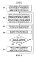
- FIG. 6 an illustration of a process for controlling tooling operations is depicted in the form of a flowchart in accordance with an illustrative embodiment.
- the process illustrated in Figure 6 may be implemented using calibration system 322 in Figure 3 .
- the process may begin by identifying an initial set of parameter values for a set of parameters for a tooling system as a current set of parameter values to be evaluated (operation 600 ).
- the current set of parameter values may be modified iteratively, until the current set of parameter values are determined to result in a tooling operation producing an output that meets a set of criteria, to form a final set of parameter values (operation 602 ).
- the tooling operation may then be performed using the final set of parameter values (operation 604 ).
- Sensor data may be generated about the output of the tooling operation (operation 606 ).
- a determination may be made as to whether the output of the tooling operation meets the set of criteria (operation 608 ).
- the process proceeds to operation 604 as described above. Otherwise, a new set of parameter values may be identified as the current set of parameter values to be evaluated (operation 610 ). The process may then return to operation 602 as described above.
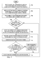
- FIG. 7 an illustration of a process for controlling riveting operations is depicted in the form of a flowchart in accordance with an illustrative embodiment.
- the process illustrated in Figure 7 may be implemented using calibration system 322 in Figure 3 .
- the process may begin by identifying an initial set of parameter values for a set of parameters for a riveting system as a current set of parameter values to be evaluated (operation 700 ).
- a rivet that would be formed by the riveting system based on the current set of parameter values may be modeled using finite-element assisted modeling (operation 702 ).
- a number of tests and/or simulations may be run based on a modeled rivet to generate test data (operation 704 ).
- the test data generated in operation 704 may be digital test data.
- a determination is made as to whether the modeled rivet meets a set of criteria based on the test data (operation 706 ).
- the current set of parameter values being evaluated are output as a final set of parameter values to a controller configured to control the riveting system (operation 708 ).
- the calibration system then waits until the rivet has been formed by the riveting system using the final set of parameter values (operation 710 ).
- Sensor data is then generated for the rivet formed (operation 712 ).
- a determination is made as to whether a set of properties for the rivet meets the set of criteria based on the sensor data (operation 714 ). If the set of properties for the rivet meet the set of criteria, the process sends an indication to the controller to continue using the current set of parameter values (operation 716 ), with the process then returning to operation 710 as described above.
- the process selects a new set of parameter values for evaluation (operation 718 ). The process then returns to operation 702 as described above. With reference again to operation 706, if the modeled rivet does not meet the set of criteria based on the test data, the process proceeds to operation 718 as described above.
- Data processing system 800 may be used to implement one or more computers in computer system 324, supercomputer 328, modeler 338, parameter modifier 345, quality checker 356, a processor unit in one or more of number of sensor devices 330 in sensor system 326, and/or controller 348 in Figure 3 .
- data processing system 800 includes communications framework 802, which provides communications between processor unit 804, storage devices 806, communications unit 808, input/output unit 810, and display 812.
- communications framework 802 may be implemented as a bus system.
- Processor unit 804 is configured to execute instructions for software to perform a number of operations.
- Processor unit 804 may comprise a number of processors, a multi-processor core, and/or some other type of processor, depending on the implementation.
- processor unit 804 may take the form of a hardware unit, such as a circuit system, an application specific integrated circuit (ASIC), a programmable logic device, or some other suitable type of hardware unit.
- ASIC application specific integrated circuit
- Storage devices 806 may be in communication with processor unit 804 through communications framework 802.
- a storage device also referred to as a computer readable storage device, is any piece of hardware capable of storing information on a temporary and/or permanent basis. This information may include, but is not limited to, data, program code, and/or other information.
- Memory 814 and persistent storage 816 are examples of storage devices 806.
- Memory 814 may take the form of, for example, a random access memory or some type of volatile or nonvolatile storage device.
- Persistent storage 816 may comprise any number of components or devices.
- persistent storage 816 may comprise a hard drive, a flash memory, a rewritable optical disk, a rewritable magnetic tape, or some combination of the above.
- the media used by persistent storage 816 may or may not be removable.
- Communications unit 808 allows data processing system 800 to communicate with other data processing systems and/or devices. Communications unit 808 may provide communications using physical and/or wireless communications links.
- Input/output unit 810 allows input to be received from and output to be sent to other devices connected to data processing system 800.
- input/output unit 810 may allow user input to be received through a keyboard, a mouse, and/or some other type of input device.
- input/output unit 810 may allow output to be sent to a printer connected to data processing system 800.
- Display 812 is configured to display information to a user.
- Display 812 may comprise, for example, without limitation, a monitor, a touch screen, a laser display, a holographic display, a virtual display device, and/or some other type of display device.
- processor unit 804 may perform the processes of the different illustrative embodiments using computer-implemented instructions. These instructions may be referred to as program code, computer usable program code, or computer readable program code and may be read and executed by one or more processors in processor unit 804.
- program code 818 is located in a functional form on computer readable media 820, which is selectively removable, and may be loaded onto or transferred to data processing system 800 for execution by processor unit 804.
- Program code 818 and computer readable media 820 together form computer program product 822.
- computer readable media 820 may be computer readable storage media 824 or computer readable signal media 826.
- Computer readable storage media 824 is a physical or tangible storage device used to store program code 818 rather than a medium that propagates or transmits program code 818.
- Computer readable storage media 824 may be, for example, without limitation, an optical or magnetic disk or a persistent storage device that is connected to data processing system 800.
- program code 818 may be transferred to data processing system 800 using computer readable signal media 826.
- Computer readable signal media 826 may be, for example, a propagated data signal containing program code 818. This data signal may be an electromagnetic signal, an optical signal, and/or some other type of signal that can be transmitted over physical and/or wireless communications links.
- data processing system 800 in Figure 8 is not meant to provide architectural limitations to the manner in which the illustrative embodiments may be implemented.
- the different illustrative embodiments may be implemented in a data processing system that includes components in addition to or in place of those illustrated for data processing system 800. Further, components shown in Figure 8 may be varied from the illustrative examples shown.
- each block in the flowcharts or block diagrams may represent a module, a segment, a function, and/or a portion of an operation or step.
- the function or functions noted in the blocks may occur out of the order noted in the figures.
- two blocks shown in succession may be executed substantially concurrently, or the blocks may sometimes be performed in the reverse order, depending upon the functionality involved.
- other blocks may be added in addition to the illustrated blocks in a flowchart or block diagram.
Landscapes
- Engineering & Computer Science (AREA)
- Physics & Mathematics (AREA)
- General Physics & Mathematics (AREA)
- Automation & Control Theory (AREA)
- Mechanical Engineering (AREA)
- Manufacturing & Machinery (AREA)
- General Engineering & Computer Science (AREA)
- Quality & Reliability (AREA)
- Health & Medical Sciences (AREA)
- Artificial Intelligence (AREA)
- Computer Vision & Pattern Recognition (AREA)
- Evolutionary Computation (AREA)
- Medical Informatics (AREA)
- Software Systems (AREA)
- Automatic Assembly (AREA)
- General Factory Administration (AREA)
- Feedback Control In General (AREA)
Applications Claiming Priority (1)
| Application Number | Priority Date | Filing Date | Title |
|---|---|---|---|
| US13/929,138 US10162317B2 (en) | 2013-06-27 | 2013-06-27 | Real-time feedback control for performing tooling operations in assembly processes |
Publications (3)
| Publication Number | Publication Date |
|---|---|
| EP2821871A2 true EP2821871A2 (de) | 2015-01-07 |
| EP2821871A3 EP2821871A3 (de) | 2016-11-02 |
| EP2821871B1 EP2821871B1 (de) | 2021-03-24 |
Family
ID=51032934
Family Applications (1)
| Application Number | Title | Priority Date | Filing Date |
|---|---|---|---|
| EP14172964.0A Active EP2821871B1 (de) | 2013-06-27 | 2014-06-18 | Echtzeit-Rückkopplungsteuerung für Werkzeugoperationen in Montageverfahren |
Country Status (6)
| Country | Link |
|---|---|
| US (1) | US10162317B2 (de) |
| EP (1) | EP2821871B1 (de) |
| JP (1) | JP6654342B2 (de) |
| KR (1) | KR102196788B1 (de) |
| CN (1) | CN104252403B (de) |
| CA (1) | CA2851451C (de) |
Cited By (3)
| Publication number | Priority date | Publication date | Assignee | Title |
|---|---|---|---|---|
| EP3062095A1 (de) * | 2015-02-27 | 2016-08-31 | The Boeing Company | Erkennung von lücken zwischen befestigungselementen und öffnungen |
| CN112536419A (zh) * | 2020-11-04 | 2021-03-23 | 江门市安诺特炊具制造有限公司 | 自动装钉机 |
| EP4012826A1 (de) * | 2020-12-14 | 2022-06-15 | Prime Planet Energy & Solutions, Inc. | Batterie und verfahren zu ihrer herstellung |
Families Citing this family (15)
| Publication number | Priority date | Publication date | Assignee | Title |
|---|---|---|---|---|
| EP3045993A1 (de) * | 2015-01-15 | 2016-07-20 | Siemens Aktiengesellschaft | Fertigungssystem mit zusätzlicher Funktionalität und Betriebsverfahren |
| DE102015211308A1 (de) * | 2015-06-19 | 2016-12-22 | Robert Bosch Gmbh | Werkzeugsystem für eine Montageanlage mit anwenderspezifischem Bericht und ein Verfahren für ein Werkzeugsystem einer Monateanlage |
| DE102015226188A1 (de) * | 2015-12-21 | 2017-06-22 | Robert Bosch Gmbh | Verfahren zu einer Sicherung einer Benutzung zumindest einer Handwerkzeugmaschine |
| US10571260B2 (en) * | 2017-09-06 | 2020-02-25 | The Boeing Company | Automated rivet measurement system |
| CN108543899B (zh) * | 2018-03-22 | 2024-04-23 | 南京信息职业技术学院 | 一种气动冲击锻打机构 |
| JP6802213B2 (ja) * | 2018-04-26 | 2020-12-16 | ファナック株式会社 | 工具選定装置及び機械学習装置 |
| US11308456B2 (en) | 2018-05-22 | 2022-04-19 | Microsoft Technology Licensing, Llc | Feedback based automated maintenance system |
| JP6628952B1 (ja) | 2018-10-19 | 2020-01-15 | 株式会社津田工業 | クリンチングファスナ圧入方法、及びこの圧入方法に用いられるファスナリング治具 |
| WO2020079974A1 (ja) * | 2018-10-19 | 2020-04-23 | 株式会社津田工業 | クリンチングファスナ圧入方法、及びこの圧入方法に用いられるファスナリング治具 |
| US11364623B2 (en) * | 2019-02-15 | 2022-06-21 | GM Global Technology Operations LLC | Component assembly system |
| CN110355322B (zh) * | 2019-07-11 | 2021-07-13 | 爱驰汽车有限公司 | 铆模选取系统及方法 |
| CN110443478B (zh) * | 2019-07-24 | 2023-04-07 | 清华大学天津高端装备研究院 | 一种基于mes的人员绩效分析方法 |
| CN112861388B (zh) * | 2019-11-26 | 2023-07-25 | 中国科学院沈阳自动化研究所 | 一种基于正交设计的协作机器人全域结构优化设计方法 |
| KR102562384B1 (ko) * | 2021-04-06 | 2023-08-02 | 사단법인 캠틱종합기술원 | 상용차용 크로스멤버 리벳팅 장치 |
| CN114102491A (zh) * | 2021-11-15 | 2022-03-01 | 中铁电气化局集团有限公司 | 一种夹持推送装置 |
Family Cites Families (20)
| Publication number | Priority date | Publication date | Assignee | Title |
|---|---|---|---|---|
| US3747467A (en) * | 1967-12-06 | 1973-07-24 | I Rosman | Rivet fastener system and method |
| JPS61289402A (ja) * | 1985-06-18 | 1986-12-19 | Mitsubishi Electric Corp | 数値制御装置 |
| US5402367A (en) * | 1993-07-19 | 1995-03-28 | Texas Instruments, Incorporated | Apparatus and method for model based process control |
| DE4338608B4 (de) * | 1993-11-11 | 2005-10-06 | Siemens Ag | Verfahren und Vorrichtung zur Führung eines Prozesses in einem geregelten System |
| US5917726A (en) * | 1993-11-18 | 1999-06-29 | Sensor Adaptive Machines, Inc. | Intelligent machining and manufacturing |
| KR100201020B1 (ko) | 1994-03-11 | 1999-06-15 | 모리시타 요이찌 | 컴퓨터시뮬레이션부착 nc제어미세가공방법과 이 방법에 사용하는 장치 |
| US5675887A (en) * | 1995-07-21 | 1997-10-14 | Davidson Textron Inc. | Error free rivet system |
| US6276050B1 (en) * | 1998-07-20 | 2001-08-21 | Emhart Inc. | Riveting system and process for forming a riveted joint |
| JP3000985B2 (ja) * | 1997-12-26 | 2000-01-17 | 三菱電機株式会社 | 数値制御装置 |
| US6760716B1 (en) * | 2000-06-08 | 2004-07-06 | Fisher-Rosemount Systems, Inc. | Adaptive predictive model in a process control system |
| US6550118B2 (en) * | 2001-02-02 | 2003-04-22 | Electroimpact, Inc. | Apparatus and method for accurate countersinking and rivet shaving for mechanical assembly operations |
| ITVE20010036A1 (it) * | 2001-08-08 | 2003-02-08 | Fpt Ind Spa | Metodo per effettuare in modo automatico la correzione degli errori sistematici in macchine di misura ed in macchine operatrici ed apparecch |
| EP1457853A1 (de) | 2003-03-14 | 2004-09-15 | General Electric Company | Verfahren und Vorrichtung zur Rück- und Rekonstruktion von Teilen |
| US7191032B2 (en) * | 2004-05-14 | 2007-03-13 | Novelis Inc. | Methods of and apparatus for forming hollow metal articles |
| US7451004B2 (en) * | 2005-09-30 | 2008-11-11 | Fisher-Rosemount Systems, Inc. | On-line adaptive model predictive control in a process control system |
| DE102007025447A1 (de) * | 2006-10-09 | 2008-04-17 | Siemens Ag | Verfahren zur Steuerung und/oder Regelung eines industriellen Prozesses |
| US7620150B1 (en) * | 2007-01-30 | 2009-11-17 | Martin Annis | X-ray backscatter system for imaging at shallow depths |
| US7933679B1 (en) * | 2007-10-23 | 2011-04-26 | Cessna Aircraft Company | Method for analyzing and optimizing a machining process |
| US7983387B1 (en) | 2009-10-20 | 2011-07-19 | The Boeing Company | Method and system to predict detectability and identify foreign objects |
| US9021677B1 (en) * | 2012-01-12 | 2015-05-05 | Gemcor Ii, Llc | Apparatus and method for improving safety and quality of automatic riveting operations |
-
2013
- 2013-06-27 US US13/929,138 patent/US10162317B2/en not_active Expired - Fee Related
-
2014
- 2014-05-09 CA CA2851451A patent/CA2851451C/en active Active
- 2014-06-09 KR KR1020140069162A patent/KR102196788B1/ko active IP Right Grant
- 2014-06-18 EP EP14172964.0A patent/EP2821871B1/de active Active
- 2014-06-23 JP JP2014127901A patent/JP6654342B2/ja not_active Expired - Fee Related
- 2014-06-26 CN CN201410298597.2A patent/CN104252403B/zh not_active Expired - Fee Related
Non-Patent Citations (1)
| Title |
|---|
| None |
Cited By (4)
| Publication number | Priority date | Publication date | Assignee | Title |
|---|---|---|---|---|
| EP3062095A1 (de) * | 2015-02-27 | 2016-08-31 | The Boeing Company | Erkennung von lücken zwischen befestigungselementen und öffnungen |
| CN105928473A (zh) * | 2015-02-27 | 2016-09-07 | 波音公司 | 检测紧固件和开孔之间的间隙 |
| CN112536419A (zh) * | 2020-11-04 | 2021-03-23 | 江门市安诺特炊具制造有限公司 | 自动装钉机 |
| EP4012826A1 (de) * | 2020-12-14 | 2022-06-15 | Prime Planet Energy & Solutions, Inc. | Batterie und verfahren zu ihrer herstellung |
Also Published As
| Publication number | Publication date |
|---|---|
| KR102196788B1 (ko) | 2020-12-31 |
| US20150005945A1 (en) | 2015-01-01 |
| EP2821871B1 (de) | 2021-03-24 |
| JP2015027726A (ja) | 2015-02-12 |
| US10162317B2 (en) | 2018-12-25 |
| CA2851451A1 (en) | 2014-12-27 |
| JP6654342B2 (ja) | 2020-02-26 |
| EP2821871A3 (de) | 2016-11-02 |
| CA2851451C (en) | 2017-10-17 |
| CN104252403B (zh) | 2019-05-31 |
| KR20150001620A (ko) | 2015-01-06 |
| CN104252403A (zh) | 2014-12-31 |
Similar Documents
| Publication | Publication Date | Title |
|---|---|---|
| CA2851451C (en) | Real-time feedback control for performing tooling operations in assembly processes | |
| Xie et al. | Variation propagation analysis on compliant assemblies considering contact interaction | |
| US9469029B2 (en) | Method and apparatus for saving energy and reducing cycle time by optimal ordering of the industrial robotic path | |
| US9547303B2 (en) | Managing the manufacturing lifecycle of fasteners of a product | |
| EP2993001A1 (de) | Verfahren und vorrichtung zur optimierung der energieeinsparung bei industriellen robotern mittels vorbeiflug | |
| EP2979825A1 (de) | Verfahren und vorrichtung zur energieeinsparung und reduzierung der zykluszeit mittels optimalen robotischen gelenkkonfigurationen | |
| EP2942685B1 (de) | Verfahren zur robotischen suche nach energiesparendem werkzeug | |
| Wang et al. | Identifying sources of variation in horizontal stabilizer assembly using finite element analysis and principal component analysis | |
| EP2998078A1 (de) | Verfahren zur verbesserung der effizienz des energieverbrauchs und der zykluszeit von industrierobotern durch die handhabung der ausrichtung bei dem bearbeitungsort | |
| EP2990164B1 (de) | Verfahren und vorrichtung und effiziente lokalisierungserzeugung für kooperative bewegung | |
| Damrath et al. | Establishing energy efficiency as criterion for virtual commissioning of automated assembly systems | |
| US8666533B2 (en) | System, method, and interface for virtual commissioning of press lines | |
| Ruediger et al. | Dealing with uncertainties in manufacturing process simulations | |
| Zhao et al. | Prediction of assembly variation during early design | |
| Song et al. | Model-based cyber-physical system integration in the process industry | |
| Catelani | From the digital-twin to the cyber physical system using integrated multidisciplinary simulation: Virtualization of complex systems | |
| Myers | Rapid Qualification of Additive Manufactured Parts Using OpenMETA | |
| WO2011156101A1 (en) | System and method for physics-oriented system configuration | |
| Shetty et al. | Virtual Product Design Using Innovative Mechatronic Techniques for Global Supply Chain | |
| Bjerge et al. | Using VDM in a Co-Simulation Setting for an Industrial Conveyor System | |
| Nguyen et al. | Integration of multiphysical phenomena in robust design methodology | |
| US20110144784A1 (en) | System and method for embedding and using intelligent product manufacturing information stored in cad model objects | |
| Wagersten et al. | Non-FEA-Based Method as Means for Knowledge Based Assessment of Perceived Quality | |
| Lin et al. | An Expert Framework Aide for Determining Optimal Design Models |
Legal Events
| Date | Code | Title | Description |
|---|---|---|---|
| PUAI | Public reference made under article 153(3) epc to a published international application that has entered the european phase |
Free format text: ORIGINAL CODE: 0009012 |
|
| 17P | Request for examination filed |
Effective date: 20140618 |
|
| AK | Designated contracting states |
Kind code of ref document: A2 Designated state(s): AL AT BE BG CH CY CZ DE DK EE ES FI FR GB GR HR HU IE IS IT LI LT LU LV MC MK MT NL NO PL PT RO RS SE SI SK SM TR |
|
| AX | Request for extension of the european patent |
Extension state: BA ME |
|
| PUAL | Search report despatched |
Free format text: ORIGINAL CODE: 0009013 |
|
| AK | Designated contracting states |
Kind code of ref document: A3 Designated state(s): AL AT BE BG CH CY CZ DE DK EE ES FI FR GB GR HR HU IE IS IT LI LT LU LV MC MK MT NL NO PL PT RO RS SE SI SK SM TR |
|
| AX | Request for extension of the european patent |
Extension state: BA ME |
|
| RIC1 | Information provided on ipc code assigned before grant |
Ipc: B21J 15/28 20060101ALN20160923BHEP Ipc: G05B 19/418 20060101AFI20160923BHEP Ipc: G05B 13/04 20060101ALI20160923BHEP |
|
| STAA | Information on the status of an ep patent application or granted ep patent |
Free format text: STATUS: EXAMINATION IS IN PROGRESS |
|
| 17Q | First examination report despatched |
Effective date: 20190401 |
|
| GRAP | Despatch of communication of intention to grant a patent |
Free format text: ORIGINAL CODE: EPIDOSNIGR1 |
|
| STAA | Information on the status of an ep patent application or granted ep patent |
Free format text: STATUS: GRANT OF PATENT IS INTENDED |
|
| RIC1 | Information provided on ipc code assigned before grant |
Ipc: B21J 15/02 20060101ALI20201029BHEP Ipc: B21J 15/28 20060101ALN20201029BHEP Ipc: G05B 19/418 20060101AFI20201029BHEP Ipc: G05B 13/04 20060101ALI20201029BHEP |
|
| INTG | Intention to grant announced |
Effective date: 20201118 |
|
| GRAS | Grant fee paid |
Free format text: ORIGINAL CODE: EPIDOSNIGR3 |
|
| GRAA | (expected) grant |
Free format text: ORIGINAL CODE: 0009210 |
|
| STAA | Information on the status of an ep patent application or granted ep patent |
Free format text: STATUS: THE PATENT HAS BEEN GRANTED |
|
| AK | Designated contracting states |
Kind code of ref document: B1 Designated state(s): AL AT BE BG CH CY CZ DE DK EE ES FI FR GB GR HR HU IE IS IT LI LT LU LV MC MK MT NL NO PL PT RO RS SE SI SK SM TR |
|
| REG | Reference to a national code |
Ref country code: GB Ref legal event code: FG4D |
|
| REG | Reference to a national code |
Ref country code: CH Ref legal event code: EP |
|
| REG | Reference to a national code |
Ref country code: IE Ref legal event code: FG4D |
|
| REG | Reference to a national code |
Ref country code: AT Ref legal event code: REF Ref document number: 1375113 Country of ref document: AT Kind code of ref document: T Effective date: 20210415 Ref country code: DE Ref legal event code: R096 Ref document number: 602014075896 Country of ref document: DE |
|
| REG | Reference to a national code |
Ref country code: LT Ref legal event code: MG9D |
|
| PG25 | Lapsed in a contracting state [announced via postgrant information from national office to epo] |
Ref country code: NO Free format text: LAPSE BECAUSE OF FAILURE TO SUBMIT A TRANSLATION OF THE DESCRIPTION OR TO PAY THE FEE WITHIN THE PRESCRIBED TIME-LIMIT Effective date: 20210624 Ref country code: BG Free format text: LAPSE BECAUSE OF FAILURE TO SUBMIT A TRANSLATION OF THE DESCRIPTION OR TO PAY THE FEE WITHIN THE PRESCRIBED TIME-LIMIT Effective date: 20210624 Ref country code: GR Free format text: LAPSE BECAUSE OF FAILURE TO SUBMIT A TRANSLATION OF THE DESCRIPTION OR TO PAY THE FEE WITHIN THE PRESCRIBED TIME-LIMIT Effective date: 20210625 Ref country code: FI Free format text: LAPSE BECAUSE OF FAILURE TO SUBMIT A TRANSLATION OF THE DESCRIPTION OR TO PAY THE FEE WITHIN THE PRESCRIBED TIME-LIMIT Effective date: 20210324 Ref country code: HR Free format text: LAPSE BECAUSE OF FAILURE TO SUBMIT A TRANSLATION OF THE DESCRIPTION OR TO PAY THE FEE WITHIN THE PRESCRIBED TIME-LIMIT Effective date: 20210324 |
|
| PGFP | Annual fee paid to national office [announced via postgrant information from national office to epo] |
Ref country code: FR Payment date: 20210625 Year of fee payment: 8 Ref country code: DE Payment date: 20210629 Year of fee payment: 8 |
|
| PG25 | Lapsed in a contracting state [announced via postgrant information from national office to epo] |
Ref country code: LV Free format text: LAPSE BECAUSE OF FAILURE TO SUBMIT A TRANSLATION OF THE DESCRIPTION OR TO PAY THE FEE WITHIN THE PRESCRIBED TIME-LIMIT Effective date: 20210324 Ref country code: RS Free format text: LAPSE BECAUSE OF FAILURE TO SUBMIT A TRANSLATION OF THE DESCRIPTION OR TO PAY THE FEE WITHIN THE PRESCRIBED TIME-LIMIT Effective date: 20210324 Ref country code: SE Free format text: LAPSE BECAUSE OF FAILURE TO SUBMIT A TRANSLATION OF THE DESCRIPTION OR TO PAY THE FEE WITHIN THE PRESCRIBED TIME-LIMIT Effective date: 20210324 |
|
| PGFP | Annual fee paid to national office [announced via postgrant information from national office to epo] |
Ref country code: GB Payment date: 20210628 Year of fee payment: 8 |
|
| REG | Reference to a national code |
Ref country code: NL Ref legal event code: MP Effective date: 20210324 |
|
| REG | Reference to a national code |
Ref country code: AT Ref legal event code: MK05 Ref document number: 1375113 Country of ref document: AT Kind code of ref document: T Effective date: 20210324 |
|
| PG25 | Lapsed in a contracting state [announced via postgrant information from national office to epo] |
Ref country code: NL Free format text: LAPSE BECAUSE OF FAILURE TO SUBMIT A TRANSLATION OF THE DESCRIPTION OR TO PAY THE FEE WITHIN THE PRESCRIBED TIME-LIMIT Effective date: 20210324 |
|
| PG25 | Lapsed in a contracting state [announced via postgrant information from national office to epo] |
Ref country code: SM Free format text: LAPSE BECAUSE OF FAILURE TO SUBMIT A TRANSLATION OF THE DESCRIPTION OR TO PAY THE FEE WITHIN THE PRESCRIBED TIME-LIMIT Effective date: 20210324 Ref country code: EE Free format text: LAPSE BECAUSE OF FAILURE TO SUBMIT A TRANSLATION OF THE DESCRIPTION OR TO PAY THE FEE WITHIN THE PRESCRIBED TIME-LIMIT Effective date: 20210324 Ref country code: CZ Free format text: LAPSE BECAUSE OF FAILURE TO SUBMIT A TRANSLATION OF THE DESCRIPTION OR TO PAY THE FEE WITHIN THE PRESCRIBED TIME-LIMIT Effective date: 20210324 Ref country code: LT Free format text: LAPSE BECAUSE OF FAILURE TO SUBMIT A TRANSLATION OF THE DESCRIPTION OR TO PAY THE FEE WITHIN THE PRESCRIBED TIME-LIMIT Effective date: 20210324 Ref country code: AT Free format text: LAPSE BECAUSE OF FAILURE TO SUBMIT A TRANSLATION OF THE DESCRIPTION OR TO PAY THE FEE WITHIN THE PRESCRIBED TIME-LIMIT Effective date: 20210324 |
|
| PG25 | Lapsed in a contracting state [announced via postgrant information from national office to epo] |
Ref country code: PT Free format text: LAPSE BECAUSE OF FAILURE TO SUBMIT A TRANSLATION OF THE DESCRIPTION OR TO PAY THE FEE WITHIN THE PRESCRIBED TIME-LIMIT Effective date: 20210726 Ref country code: PL Free format text: LAPSE BECAUSE OF FAILURE TO SUBMIT A TRANSLATION OF THE DESCRIPTION OR TO PAY THE FEE WITHIN THE PRESCRIBED TIME-LIMIT Effective date: 20210324 Ref country code: ES Free format text: LAPSE BECAUSE OF FAILURE TO SUBMIT A TRANSLATION OF THE DESCRIPTION OR TO PAY THE FEE WITHIN THE PRESCRIBED TIME-LIMIT Effective date: 20210324 Ref country code: SK Free format text: LAPSE BECAUSE OF FAILURE TO SUBMIT A TRANSLATION OF THE DESCRIPTION OR TO PAY THE FEE WITHIN THE PRESCRIBED TIME-LIMIT Effective date: 20210324 Ref country code: RO Free format text: LAPSE BECAUSE OF FAILURE TO SUBMIT A TRANSLATION OF THE DESCRIPTION OR TO PAY THE FEE WITHIN THE PRESCRIBED TIME-LIMIT Effective date: 20210324 Ref country code: IS Free format text: LAPSE BECAUSE OF FAILURE TO SUBMIT A TRANSLATION OF THE DESCRIPTION OR TO PAY THE FEE WITHIN THE PRESCRIBED TIME-LIMIT Effective date: 20210724 |
|
| REG | Reference to a national code |
Ref country code: DE Ref legal event code: R097 Ref document number: 602014075896 Country of ref document: DE |
|
| PG25 | Lapsed in a contracting state [announced via postgrant information from national office to epo] |
Ref country code: AL Free format text: LAPSE BECAUSE OF FAILURE TO SUBMIT A TRANSLATION OF THE DESCRIPTION OR TO PAY THE FEE WITHIN THE PRESCRIBED TIME-LIMIT Effective date: 20210324 Ref country code: MC Free format text: LAPSE BECAUSE OF FAILURE TO SUBMIT A TRANSLATION OF THE DESCRIPTION OR TO PAY THE FEE WITHIN THE PRESCRIBED TIME-LIMIT Effective date: 20210324 Ref country code: DK Free format text: LAPSE BECAUSE OF FAILURE TO SUBMIT A TRANSLATION OF THE DESCRIPTION OR TO PAY THE FEE WITHIN THE PRESCRIBED TIME-LIMIT Effective date: 20210324 |
|
| REG | Reference to a national code |
Ref country code: CH Ref legal event code: PL |
|
| PLBE | No opposition filed within time limit |
Free format text: ORIGINAL CODE: 0009261 |
|
| STAA | Information on the status of an ep patent application or granted ep patent |
Free format text: STATUS: NO OPPOSITION FILED WITHIN TIME LIMIT |
|
| PG25 | Lapsed in a contracting state [announced via postgrant information from national office to epo] |
Ref country code: SI Free format text: LAPSE BECAUSE OF FAILURE TO SUBMIT A TRANSLATION OF THE DESCRIPTION OR TO PAY THE FEE WITHIN THE PRESCRIBED TIME-LIMIT Effective date: 20210324 |
|
| 26N | No opposition filed |
Effective date: 20220104 |
|
| REG | Reference to a national code |
Ref country code: BE Ref legal event code: MM Effective date: 20210630 |
|
| PG25 | Lapsed in a contracting state [announced via postgrant information from national office to epo] |
Ref country code: LU Free format text: LAPSE BECAUSE OF NON-PAYMENT OF DUE FEES Effective date: 20210618 |
|
| PG25 | Lapsed in a contracting state [announced via postgrant information from national office to epo] |
Ref country code: LI Free format text: LAPSE BECAUSE OF NON-PAYMENT OF DUE FEES Effective date: 20210630 Ref country code: IE Free format text: LAPSE BECAUSE OF NON-PAYMENT OF DUE FEES Effective date: 20210618 Ref country code: CH Free format text: LAPSE BECAUSE OF NON-PAYMENT OF DUE FEES Effective date: 20210630 |
|
| PG25 | Lapsed in a contracting state [announced via postgrant information from national office to epo] |
Ref country code: IS Free format text: LAPSE BECAUSE OF FAILURE TO SUBMIT A TRANSLATION OF THE DESCRIPTION OR TO PAY THE FEE WITHIN THE PRESCRIBED TIME-LIMIT Effective date: 20210724 |
|
| PG25 | Lapsed in a contracting state [announced via postgrant information from national office to epo] |
Ref country code: BE Free format text: LAPSE BECAUSE OF NON-PAYMENT OF DUE FEES Effective date: 20210630 |
|
| REG | Reference to a national code |
Ref country code: DE Ref legal event code: R119 Ref document number: 602014075896 Country of ref document: DE |
|
| PG25 | Lapsed in a contracting state [announced via postgrant information from national office to epo] |
Ref country code: IT Free format text: LAPSE BECAUSE OF FAILURE TO SUBMIT A TRANSLATION OF THE DESCRIPTION OR TO PAY THE FEE WITHIN THE PRESCRIBED TIME-LIMIT Effective date: 20210324 |
|
| GBPC | Gb: european patent ceased through non-payment of renewal fee |
Effective date: 20220618 |
|
| PG25 | Lapsed in a contracting state [announced via postgrant information from national office to epo] |
Ref country code: FR Free format text: LAPSE BECAUSE OF NON-PAYMENT OF DUE FEES Effective date: 20220630 |
|
| PG25 | Lapsed in a contracting state [announced via postgrant information from national office to epo] |
Ref country code: HU Free format text: LAPSE BECAUSE OF FAILURE TO SUBMIT A TRANSLATION OF THE DESCRIPTION OR TO PAY THE FEE WITHIN THE PRESCRIBED TIME-LIMIT; INVALID AB INITIO Effective date: 20140618 Ref country code: GB Free format text: LAPSE BECAUSE OF NON-PAYMENT OF DUE FEES Effective date: 20220618 Ref country code: DE Free format text: LAPSE BECAUSE OF NON-PAYMENT OF DUE FEES Effective date: 20230103 |
|
| PG25 | Lapsed in a contracting state [announced via postgrant information from national office to epo] |
Ref country code: CY Free format text: LAPSE BECAUSE OF FAILURE TO SUBMIT A TRANSLATION OF THE DESCRIPTION OR TO PAY THE FEE WITHIN THE PRESCRIBED TIME-LIMIT Effective date: 20210324 |
|
| PG25 | Lapsed in a contracting state [announced via postgrant information from national office to epo] |
Ref country code: MK Free format text: LAPSE BECAUSE OF FAILURE TO SUBMIT A TRANSLATION OF THE DESCRIPTION OR TO PAY THE FEE WITHIN THE PRESCRIBED TIME-LIMIT Effective date: 20210324 |