EP2821871A2 - Real-time feedback control for performing tooling operations in assembly processes - Google Patents
Real-time feedback control for performing tooling operations in assembly processes Download PDFInfo
- Publication number
- EP2821871A2 EP2821871A2 EP14172964.0A EP14172964A EP2821871A2 EP 2821871 A2 EP2821871 A2 EP 2821871A2 EP 14172964 A EP14172964 A EP 14172964A EP 2821871 A2 EP2821871 A2 EP 2821871A2
- Authority
- EP
- European Patent Office
- Prior art keywords
- parameter values
- tooling
- output
- criteria
- tooling operation
- Prior art date
- Legal status (The legal status is an assumption and is not a legal conclusion. Google has not performed a legal analysis and makes no representation as to the accuracy of the status listed.)
- Granted
Links
Images


Classifications
-
- G—PHYSICS
- G05—CONTROLLING; REGULATING
- G05B—CONTROL OR REGULATING SYSTEMS IN GENERAL; FUNCTIONAL ELEMENTS OF SUCH SYSTEMS; MONITORING OR TESTING ARRANGEMENTS FOR SUCH SYSTEMS OR ELEMENTS
- G05B15/00—Systems controlled by a computer
- G05B15/02—Systems controlled by a computer electric
-
- B—PERFORMING OPERATIONS; TRANSPORTING
- B21—MECHANICAL METAL-WORKING WITHOUT ESSENTIALLY REMOVING MATERIAL; PUNCHING METAL
- B21J—FORGING; HAMMERING; PRESSING METAL; RIVETING; FORGE FURNACES
- B21J15/00—Riveting
- B21J15/02—Riveting procedures
-
- B—PERFORMING OPERATIONS; TRANSPORTING
- B21—MECHANICAL METAL-WORKING WITHOUT ESSENTIALLY REMOVING MATERIAL; PUNCHING METAL
- B21J—FORGING; HAMMERING; PRESSING METAL; RIVETING; FORGE FURNACES
- B21J15/00—Riveting
- B21J15/10—Riveting machines
- B21J15/28—Control devices specially adapted to riveting machines not restricted to one of the preceding subgroups
- B21J15/285—Control devices specially adapted to riveting machines not restricted to one of the preceding subgroups for controlling the rivet upset cycle
-
- G—PHYSICS
- G05—CONTROLLING; REGULATING
- G05B—CONTROL OR REGULATING SYSTEMS IN GENERAL; FUNCTIONAL ELEMENTS OF SUCH SYSTEMS; MONITORING OR TESTING ARRANGEMENTS FOR SUCH SYSTEMS OR ELEMENTS
- G05B13/00—Adaptive control systems, i.e. systems automatically adjusting themselves to have a performance which is optimum according to some preassigned criterion
- G05B13/02—Adaptive control systems, i.e. systems automatically adjusting themselves to have a performance which is optimum according to some preassigned criterion electric
- G05B13/04—Adaptive control systems, i.e. systems automatically adjusting themselves to have a performance which is optimum according to some preassigned criterion electric involving the use of models or simulators
- G05B13/042—Adaptive control systems, i.e. systems automatically adjusting themselves to have a performance which is optimum according to some preassigned criterion electric involving the use of models or simulators in which a parameter or coefficient is automatically adjusted to optimise the performance
-
- G—PHYSICS
- G05—CONTROLLING; REGULATING
- G05B—CONTROL OR REGULATING SYSTEMS IN GENERAL; FUNCTIONAL ELEMENTS OF SUCH SYSTEMS; MONITORING OR TESTING ARRANGEMENTS FOR SUCH SYSTEMS OR ELEMENTS
- G05B19/00—Programme-control systems
- G05B19/02—Programme-control systems electric
- G05B19/418—Total factory control, i.e. centrally controlling a plurality of machines, e.g. direct or distributed numerical control [DNC], flexible manufacturing systems [FMS], integrated manufacturing systems [IMS], computer integrated manufacturing [CIM]
- G05B19/41805—Total factory control, i.e. centrally controlling a plurality of machines, e.g. direct or distributed numerical control [DNC], flexible manufacturing systems [FMS], integrated manufacturing systems [IMS], computer integrated manufacturing [CIM] characterised by assembly
-
- G—PHYSICS
- G05—CONTROLLING; REGULATING
- G05B—CONTROL OR REGULATING SYSTEMS IN GENERAL; FUNCTIONAL ELEMENTS OF SUCH SYSTEMS; MONITORING OR TESTING ARRANGEMENTS FOR SUCH SYSTEMS OR ELEMENTS
- G05B19/00—Programme-control systems
- G05B19/02—Programme-control systems electric
- G05B19/418—Total factory control, i.e. centrally controlling a plurality of machines, e.g. direct or distributed numerical control [DNC], flexible manufacturing systems [FMS], integrated manufacturing systems [IMS], computer integrated manufacturing [CIM]
- G05B19/41885—Total factory control, i.e. centrally controlling a plurality of machines, e.g. direct or distributed numerical control [DNC], flexible manufacturing systems [FMS], integrated manufacturing systems [IMS], computer integrated manufacturing [CIM] characterised by modeling, simulation of the manufacturing system
-
- G—PHYSICS
- G05—CONTROLLING; REGULATING
- G05B—CONTROL OR REGULATING SYSTEMS IN GENERAL; FUNCTIONAL ELEMENTS OF SUCH SYSTEMS; MONITORING OR TESTING ARRANGEMENTS FOR SUCH SYSTEMS OR ELEMENTS
- G05B2219/00—Program-control systems
- G05B2219/30—Nc systems
- G05B2219/31—From computer integrated manufacturing till monitoring
- G05B2219/31031—Assembly, manipulator cell
-
- G—PHYSICS
- G05—CONTROLLING; REGULATING
- G05B—CONTROL OR REGULATING SYSTEMS IN GENERAL; FUNCTIONAL ELEMENTS OF SUCH SYSTEMS; MONITORING OR TESTING ARRANGEMENTS FOR SUCH SYSTEMS OR ELEMENTS
- G05B2219/00—Program-control systems
- G05B2219/30—Nc systems
- G05B2219/32—Operator till task planning
- G05B2219/32182—If state of tool, product deviates from standard, adjust system, feedback
-
- G—PHYSICS
- G05—CONTROLLING; REGULATING
- G05B—CONTROL OR REGULATING SYSTEMS IN GENERAL; FUNCTIONAL ELEMENTS OF SUCH SYSTEMS; MONITORING OR TESTING ARRANGEMENTS FOR SUCH SYSTEMS OR ELEMENTS
- G05B2219/00—Program-control systems
- G05B2219/30—Nc systems
- G05B2219/32—Operator till task planning
- G05B2219/32216—If machining not optimized, simulate new parameters and correct machining
-
- G—PHYSICS
- G05—CONTROLLING; REGULATING
- G05B—CONTROL OR REGULATING SYSTEMS IN GENERAL; FUNCTIONAL ELEMENTS OF SUCH SYSTEMS; MONITORING OR TESTING ARRANGEMENTS FOR SUCH SYSTEMS OR ELEMENTS
- G05B2219/00—Program-control systems
- G05B2219/30—Nc systems
- G05B2219/32—Operator till task planning
- G05B2219/32359—Modeling, simulating assembly operations
-
- G—PHYSICS
- G05—CONTROLLING; REGULATING
- G05B—CONTROL OR REGULATING SYSTEMS IN GENERAL; FUNCTIONAL ELEMENTS OF SUCH SYSTEMS; MONITORING OR TESTING ARRANGEMENTS FOR SUCH SYSTEMS OR ELEMENTS
- G05B2219/00—Program-control systems
- G05B2219/30—Nc systems
- G05B2219/36—Nc in input of data, input key till input tape
- G05B2219/36252—Generate machining program based on a simulation to optimize a machine parameter
-
- G—PHYSICS
- G05—CONTROLLING; REGULATING
- G05B—CONTROL OR REGULATING SYSTEMS IN GENERAL; FUNCTIONAL ELEMENTS OF SUCH SYSTEMS; MONITORING OR TESTING ARRANGEMENTS FOR SUCH SYSTEMS OR ELEMENTS
- G05B2219/00—Program-control systems
- G05B2219/30—Nc systems
- G05B2219/37—Measurements
- G05B2219/37576—Post-process, measure worpiece after machining, use results for new or same
-
- G—PHYSICS
- G05—CONTROLLING; REGULATING
- G05B—CONTROL OR REGULATING SYSTEMS IN GENERAL; FUNCTIONAL ELEMENTS OF SUCH SYSTEMS; MONITORING OR TESTING ARRANGEMENTS FOR SUCH SYSTEMS OR ELEMENTS
- G05B2219/00—Program-control systems
- G05B2219/30—Nc systems
- G05B2219/45—Nc applications
- G05B2219/45088—Riveting robot
-
- Y—GENERAL TAGGING OF NEW TECHNOLOGICAL DEVELOPMENTS; GENERAL TAGGING OF CROSS-SECTIONAL TECHNOLOGIES SPANNING OVER SEVERAL SECTIONS OF THE IPC; TECHNICAL SUBJECTS COVERED BY FORMER USPC CROSS-REFERENCE ART COLLECTIONS [XRACs] AND DIGESTS
- Y02—TECHNOLOGIES OR APPLICATIONS FOR MITIGATION OR ADAPTATION AGAINST CLIMATE CHANGE
- Y02P—CLIMATE CHANGE MITIGATION TECHNOLOGIES IN THE PRODUCTION OR PROCESSING OF GOODS
- Y02P90/00—Enabling technologies with a potential contribution to greenhouse gas [GHG] emissions mitigation
- Y02P90/02—Total factory control, e.g. smart factories, flexible manufacturing systems [FMS] or integrated manufacturing systems [IMS]
Abstract
Description
- The production of components for manufactured objects, such as an aircraft, an aircraft engine, or some other type of object, may be a complex, expensive, and time-consuming process. Because of the tolerances required for such components and the stresses placed on these components, extensive testing may typically need to be performed on prototypes of these components. Based on the results of testing, designs of components may need to be adjusted. In some cases, a design of a component may need to be discarded and recreated.
- An object such as, for example, without limitation, an aircraft, may be formed from thousands of manufactured components. These components may need to be manufactured and assembled according to certain specifications within strict tolerances. A change order for a single component may require other changes in many other related components. In some cases, a single change order may cause a ripple effect throughout the entire production cycle of the aircraft. Further, changes to a component, even changes that are considered minor may require a full cycle of testing to ensure that these changes are made according to required specifications.
- During the assembly of an aircraft, thousands of fastener elements such as, for example, without limitation, rivets, may be used in assembling the various components of the aircraft. Rivets may vary in type, size, and/or material composition.
- Prior to using a tool to install a rivet, many iterations of testing may be required to ensure that the rivet that will be formed by the tool will meet the required specifications. Some currently available methods of testing include using trial and error testing. For example, without limitation, test coupons may be used to obtain a set of parameters for the tool that will allow the rivet to be formed according to the required specifications. Several iterations of testing using these test coupons may be needed to identify an optimal set of parameters.
- Any changes in the original design for the rivet to be formed or the components to be assembled using the rivet may require that the testing be repeated. Repeating this process may require more time and effort than desired. Further, this type of testing may require more time and be more expensive than desired. Therefore, it would be desirable to have a method and apparatus that take into account at least some of the issues discussed above, as well as other possible issues.
- In one illustrative embodiment, a method for controlling a tooling operation to be performed by a tooling system may be provided. A current set of parameter values for a set of parameters for the tooling system are modified iteratively, until the current set of parameter values are determined to result in the tooling operation producing an output that meets a set of criteria, to form a final set of parameter values. The tooling operation with the tooling system is performed using the final set of parameter values. A determination is made as to whether the output of the tooling operation meets the set of criteria based on sensor data about the output of the tooling operation. A new set of parameter values are identified as the current set of parameter values to be evaluated in response to the determination that the output of the tooling operation does not meet the set of criteria.
- In another illustrative embodiment, an apparatus comprises a modeler, a quality checker, and a parameter modifier. The modeler is configured to modify, iteratively, a current set of parameter values for a set of parameters for a tooling system, until the current set of parameter values are determined to result in a tooling operation producing an output that meets a set of criteria, to form a final set of parameter values. The quality checker is configured to determine whether the output of the tooling operation meets the set of criteria based on sensor data about the output of the tooling operation. The parameter modifier is configured to identify a new set of parameter values as the current set of parameter values to be evaluated in response to a determination that the output of the tooling operation does not meet the set of criteria.
- The features and functions can be achieved independently in various embodiments of the present disclosure or may be combined in yet other embodiments in which further details can be seen with reference to the following description and drawings.
- The novel features believed characteristic of the illustrative embodiments are set forth in the appended claims. The illustrative embodiments, however, as well as a preferred mode of use, further objectives and features thereof, will best be understood by reference to the following detailed description of an illustrative embodiment of the present disclosure when read in conjunction with the accompanying drawings, wherein:
-
Figure 1 is an illustration of a manufacturing environment in accordance with an illustrative embodiment; -
Figure 2 is an illustration of a formed rivet in accordance with an illustrative embodiment; -
Figure 3 is an illustration of a manufacturing environment in the form of a block diagram in accordance with an illustrative embodiment; -
Figure 4 is an illustration of a set of parameters for a riveting system in the form of a block diagram in accordance with an illustrative embodiment; -
Figure 5 is an illustration of a set of properties for a rivet in the form of a block diagram in accordance with an illustrative embodiment; -
Figure 6 is an illustration of a process for controlling tooling operations in the form of a flowchart in accordance with an illustrative embodiment; -
Figure 7 is an illustration of a process for controlling riveting operations in the form of a flowchart in accordance with an illustrative embodiment; and -
Figure 8 is an illustration of a data processing system in the form of a block diagram in accordance with an illustrative embodiment. - The illustrative embodiments recognize and take into account different considerations. For example, the illustrative embodiments recognize and take into account that it may be desirable to have a system for adjusting the parameters of a tooling system, such as a riveting system, in substantially real time while tooling operations are being performed. The illustrative embodiments recognize and take into account that this type of system may require using a computer system capable of performing digital modeling at speeds sufficient to generate feedback data for use in adjusting the parameters of the tooling system in real-time.
- Thus, the illustrative embodiments provide an apparatus and method for optimizing a set of parameters for a tooling system while performing tooling operations. As used herein, "optimizing" the set of parameters may mean identifying the set of parameters that allow the tooling operations to be performed according to selected criteria with the least amount of error.
- Referring now to the figures and, in particular, with reference to
Figure 1 , an illustration of a manufacturing environment is depicted in accordance with an illustrative embodiment. In this illustrative example,manufacturing environment 100 is an example of an environment in whichriveting system 102 may be used to form rivets. In particular,riveting system 102 may be used to form rivets inplate 104 andplate 106 to fasten these plates together. - As depicted,
riveting system 102 may includefirst device 108 andsecond device 110.First device 108 may include firstrobotic arm 112 andfirst tool 114.Second device 110 may include secondrobotic arm 116 andsecond tool 118. In one illustrative example,first tool 114 may be referred to as an anvil, whilesecond tool 118 may be referred to as a die. In another illustrative example, bothfirst tool 114 andsecond tool 118 may be referred to as dies. -
First tool 114 andsecond tool 118 may be configured for use in forming rivets. For example, firstrobotic arm 112 and secondrobotic arm 116 may be configured to position and movefirst tool 114 andsecond tool 118 relative toplate 104 andplate 106 to form rivets. - As depicted,
members plate 104 andplate 106. These members may be used to form rivets. Firstrobotic arm 112 may be configured to usefirst tool 114 to apply a force to a member, such asmember 120, to change a shape offirst end 132 ofmember 120. Further, secondrobotic arm 116 may be configured to usesecond tool 118 to apply a force to member 120 to change a shape ofsecond end 134 ofmember 120. More specifically,first tool 114 andsecond tool 118 may be used to deformfirst end 132 andsecond end 134 ofmember 120 such thatmember 120 becomes permanently installed throughplate 104 andplate 106. Oncefirst end 132 andsecond end 134 ofmember 120 have been deformed usingfirst tool 114 andsecond tool 118,member 120 may be referred to as a rivet. - With reference now to
Figure 2 , an illustration of a formed rivet is depicted in accordance with an illustrative embodiment. In this illustrative example, rivet 200 may be the rivet formed whenfirst tool 114 andsecond tool 118 change the shapes offirst end 132 andsecond end 134 ofmember 120 inFigure 1 . As depicted,rivet 200 may havefirst shape 202 atfirst end 132 ofrivet 200 andsecond shape 204 atsecond end 134 ofrivet 200. - A feedback control system may be used to generate feedback data based on
rivet 200 and to determine whetherrivet 200 meets a set of criteria based on the feedback data. When the feedback data indicates that the rivet has not been formed according to the set of criteria, a new set of parameters may be identified forriveting system 102 using digital modeling. This new set of parameters may then be used byriveting system 102 for the next rivet to be formed. - With reference now to
Figure 3 , an illustration of a manufacturing environment is depicted in the form of a block diagram in accordance with an illustrative embodiment. In this illustrative example,manufacturing environment 300 may be an example of an environment in whichtooling system 302 may be used. In this illustrative example,tooling system 302 may be used to perform number ofoperations 304 on number ofstructures 306. As used herein, a "number of" items may be one or more items. In this manner, number ofoperations 304 may be one or more operations. An operation in number ofoperations 304 may be referred to as a tooling operation. The tooling operation may be selected from at least one of a riveting operation, a drilling operation, a fastening operation, a nailing operation, a rotating operation, or some other type of operation. - As used herein, the phrase "at least one of," when used with a list of items, means different combinations of one or more of the listed items may be used and only one of the items in the list may be needed. The item may be a particular object, thing, or category. In other words, "at least one of" means any combination of items or number of items may be used from the list, but not all of the items in the list may be required.
- For example, "at least one of item A, item B, and item C" may mean item A; item A and item B; item B; item A, item B, and item C; or item B and item C. In some cases, "at least one of item A, item B, and item C" may mean, for example, without limitation, two of item A, one of item B, and ten of item C; four of item B and seven of item C; or some other suitable combination.
- In one illustrative example,
tooling system 302 may take the form ofriveting system 308.Riveting system 102 inFigure 1 may be an example of one implementation forriveting system 308.Riveting system 308 may be used to form rivets that are used to fasten structures in number ofstructures 306, such asfirst plate 310 andsecond plate 312, to each other. In this manner,riveting system 308 may be used to performriveting operations 314.Plate 104 andplate 106 inFigure 1 may be an example of one implementation forfirst plate 310 andsecond plate 312. - As depicted,
riveting system 308 may be configured to operate with set ofparameters 316. Set ofparameters 316 may determine the properties of the rivets formed usingriveting system 308. For example,riveting system 308 may be used to formrivet 318 having set ofproperties 320. When set ofparameters 316 are changed, set ofproperties 320 may change. - In this illustrative example,
calibration system 322 may be used to identify an initial set of values for set ofparameters 316 to be used byriveting system 308. Further,calibration system 322 may be configured to monitor the set of properties of each rivet formed usingriveting system 308 to determine whether adjustments need to be made to these values.Calibration system 322 may includecomputer system 324 andsensor system 326. -
Computer system 324 may be comprised of one or more computers depending on the implementation. When more than one computer is present incomputer system 324, these computers may be in communication with each other. In this illustrative example,computer system 324 may be implemented in the form ofsupercomputer 328.Supercomputer 328 may be comprised of any number of computers, processor units, integrated circuits, microprocessors, and/or other computer hardware and/or software components configured to collectively provide significant processing power. - In this illustrative example,
sensor system 326 may include number ofsensor devices 330. In one illustrative example, number ofsensor devices 330 may includelaser sensor device 332, backscatterx-ray sensor device 334, and/or some other type of sensor device. - Prior to number of
operations 304 being performed,computer system 324 may be configured to identify initial set ofparameter values 336 for set ofparameters 316. In some cases,computer system 324 may receive initial set ofparameter values 336 in the form of user input. Of course, in other illustrative examples,computer system 324 may randomly select initial set of parameter values 336. In still other examples,computer system 324 may select initial set ofparameter values 336 from a database of parameter values. -
Modeler 338 incomputer system 324 may be configured to receive initial set of parameter values 336.Modeler 338 may be a digital modeler.Modeler 338 may use initial set ofparameter values 336 to run number oftests 340, generate number ofmodels 341, and/or run number ofsimulations 342 to determine whether initial set ofparameter values 336 will result in a rivet being formed according to desired specifications. - For example,
modeler 338 may use finite-element assisted modeling to form number ofmodels 341 of the rivet that would be formed byriveting system 308 based on initial set of parameter values 336.Modeler 338 may then use number ofmodels 341 to run number oftests 340 and/or number ofsimulations 342 to determine whether the rivet that would be formed would meet a set of criteria specified by engineering guidelines, manufacturing guidelines, and/or design requirements. - If
modeler 338 determines that initial set ofparameter values 336 will result in a rivet being formed according to desired specifications,modeler 338 outputs these values as final set of parameter values 346. Ifmodeler 338 determines that initial set ofparameter values 336 will not result in a rivet being formed according to desired specifications,modeler 338 sends a message toparameter modifier 345 indicating that a new set of parameter values are needed.Parameter modifier 345 may identify and send new set ofparameter values 344 tomodeler 338. - This process may be iteratively performed until the current set of parameter values being evaluated have been determined to result in a rivet being formed that meets the desired specifications. These desired specifications may be, for example, set of
criteria 358. -
Controller 348 may be configured to receive final set of parameter values 346.Controller 348 may be configured to controlriveting system 308. In one illustrative example,controller 348 may be considered part ofriveting system 308. In other illustrative examples,controller 348 may be considered separate fromriveting system 308. -
Controller 348 may controlriveting system 308 to use final set ofparameter values 346 for set ofparameters 316. For example,controller 348 may send one or more commands todrive system 350 ofriveting system 308 to operatedrive system 350 based on final set of parameter values 346.Riveting system 308 may then use final set ofparameter values 346 to form a rivet, such asrivet 318. - Once
rivet 318 has been formed,sensor system 326 may be used to generatesensor data 354. In particular, number ofsensor devices 330 may be used to generatesensor data 354.Sensor data 354 may include, for example, without limitation, imaging data, x-ray data, laser imaging data, infrared data, and/or other types of data.Sensor data 354 may be sent toquality checker 356 incomputer system 324 for processing. -
Quality checker 356 may usesensor data 354 to determine whetherrivet 318 has been formed according to set ofcriteria 358. More specifically,quality checker 356 may usesensor data 354 to identify set ofproperties 320 forrivet 318 and to determine whether set ofproperties 320 meet set ofcriteria 358. - If
quality checker 356 determines that set ofproperties 320 meet set ofcriteria 358,quality checker 356 sends a message tocontroller 348 indicating that the current set of parameter values being used for set ofparameters 316 may continue being used. However, ifquality checker 356 determines that set ofproperties 320 does not meet set ofcriteria 358,quality checker 356 may send a message toparameter modifier 345 indicating that a new set of parameter values are needed. -
Parameter modifier 345 may then select new set ofparameter values 344 and send new set ofparameter values 344 to modeler 338 for processing.Modeler 338 may be configured to use new set ofparameter values 344 to run number oftests 340, generate number ofmodels 341, and/or run number ofsimulations 342 to determine whether new set ofparameter values 344 may result in a rivet being formed according to desired specifications. - As depicted,
riveting system 308 may also includeposition tracker 352.Position tracker 352 may be configured to track a position ofriveting system 308 relative to number ofstructures 306 on which number ofoperations 304 are being performed.Position tracker 352 may be configured to send position data tocontroller 348 andcontroller 348 may be configured to repositionriveting system 308 when necessary. - If
modeler 338 determines that new set ofparameter values 344 will result in a rivet being formed according to desired specifications,modeler 338 outputs these values as final set ofparameter values 346 tocontroller 348. However, ifmodeler 338 determines that new set ofparameter values 344 will not result in a rivet being formed according to desired specifications,modeler 338 sends a message toparameter modifier 345 that a different set of parameter values are needed. The process described above may be iteratively performed until new set ofparameter values 344 that will result in a rivet being formed according to desired specifications has been identified. - The processes performed by
quality checker 356,parameter modifier 345, andmodeler 338 may be performed so quickly, usingsupercomputer 328, that the set of parameter values for set ofparameters 316 may be adjusted while performing number ofoperations 304 without requiring significant delays. In this manner,calibration system 322 may provide a feedback control system forriveting system 308 that allows a set of parameter values for set ofparameters 316 forriveting system 308 to be optimized while performing number ofoperations 304. - With reference now to
Figure 4 , an illustration of set ofparameters 316 forriveting system 308 inFigure 3 is depicted in the form of a block diagram in accordance with an illustrative embodiment. As depicted, set ofparameters 316 may includespeed 400,interfacial friction conditions 402, loads 404, andgeometries 406. -
Speed 400 may be the speed at whichriveting system 308 is operated.Interfacial friction conditions 402 may identify, for example, without limitation, whether the interfaces between a first tool, such asfirst tool 114 inFigure 1 , and a first end of a rivet, such asfirst end 132 inFigure 1 , and between a second tool, such assecond tool 118 inFigure 1 , and a second end of a rivet, such assecond end 134 inFigure 1 , are dry and/or lubricated. -
Loads 404 may include the loads applied to the tools used inriveting system 308.Geometries 406 may include the geometry specifications of the tools used inriveting system 308. - For example, without limitation, loads 404 may include first tool loads 408 and second tool loads 410. First tool loads 408 may be the loads for a first tool, such as
first tool 114 inFigure 1 . Second tool loads 410 may be the loads for a second tool, such assecond tool 118 inFigure 1 . - Similarly,
geometries 406 may includefirst tool geometry 412 andsecond tool geometry 414.First tool geometry 412 may include the geometry specifications for a first tool, such asfirst tool 114 inFigure 1 .Second tool geometry 414 may include the geometry specifications for a second tool, such assecond tool 118 inFigure 1 . The geometry specifications for a tool may include a shape, length, width, and/or depth of the tool. - With reference now to
Figure 5 , an illustration of set ofproperties 320 forrivet 318 inFigure 3 is depicted in the form of a block diagram in accordance with an illustrative embodiment. As depicted, set ofproperties 320 may includefirst end shape 500,second end shape 502, and number ofinterface properties 504. -
First end shape 500 may be the shape of a first end ofrivet 318, such asfirst shape 202 offirst end 132 ofrivet 200 inFigure 2 .Second end shape 502 may be the shape of a second end ofrivet 318, such assecond shape 204 ofsecond end 134 ofrivet 200 inFigure 2 . Number ofinterface properties 504 may include, for example, without limitation, the interference fit formed by the interface betweenrivet 318,first plate 310, andsecond plate 312. - With reference now to
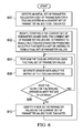
Figure 6 , an illustration of a process for controlling tooling operations is depicted in the form of a flowchart in accordance with an illustrative embodiment. The process illustrated inFigure 6 may be implemented usingcalibration system 322 inFigure 3 . - The process may begin by identifying an initial set of parameter values for a set of parameters for a tooling system as a current set of parameter values to be evaluated (operation 600). Next, the current set of parameter values may be modified iteratively, until the current set of parameter values are determined to result in a tooling operation producing an output that meets a set of criteria, to form a final set of parameter values (operation 602).
- The tooling operation may then be performed using the final set of parameter values (operation 604). Sensor data may be generated about the output of the tooling operation (operation 606). Then, a determination may be made as to whether the output of the tooling operation meets the set of criteria (operation 608).
- If the output of the tooling operation meets the set of criteria, the process proceeds to
operation 604 as described above. Otherwise, a new set of parameter values may be identified as the current set of parameter values to be evaluated (operation 610). The process may then return tooperation 602 as described above. - With reference now to
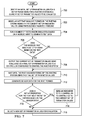
Figure 7 , an illustration of a process for controlling riveting operations is depicted in the form of a flowchart in accordance with an illustrative embodiment. The process illustrated inFigure 7 may be implemented usingcalibration system 322 inFigure 3 . - The process may begin by identifying an initial set of parameter values for a set of parameters for a riveting system as a current set of parameter values to be evaluated (operation 700). Next, a rivet that would be formed by the riveting system based on the current set of parameter values may be modeled using finite-element assisted modeling (operation 702). A number of tests and/or simulations may be run based on a modeled rivet to generate test data (operation 704). The test data generated in
operation 704 may be digital test data. A determination is made as to whether the modeled rivet meets a set of criteria based on the test data (operation 706). - If the modeled rivet meets the set of criteria, the current set of parameter values being evaluated are output as a final set of parameter values to a controller configured to control the riveting system (operation 708). The calibration system then waits until the rivet has been formed by the riveting system using the final set of parameter values (operation 710).
- Sensor data is then generated for the rivet formed (operation 712). A determination is made as to whether a set of properties for the rivet meets the set of criteria based on the sensor data (operation 714). If the set of properties for the rivet meet the set of criteria, the process sends an indication to the controller to continue using the current set of parameter values (operation 716), with the process then returning to
operation 710 as described above. - Otherwise, the process selects a new set of parameter values for evaluation (operation 718). The process then returns to
operation 702 as described above. With reference again tooperation 706, if the modeled rivet does not meet the set of criteria based on the test data, the process proceeds tooperation 718 as described above. - Turning now to
Figure 8 , an illustration of a data processing system in the form of a block diagram is depicted in accordance with an illustrative embodiment.Data processing system 800 may be used to implement one or more computers incomputer system 324,supercomputer 328,modeler 338,parameter modifier 345,quality checker 356, a processor unit in one or more of number ofsensor devices 330 insensor system 326, and/orcontroller 348 inFigure 3 . - As depicted,
data processing system 800 includescommunications framework 802, which provides communications betweenprocessor unit 804,storage devices 806,communications unit 808, input/output unit 810, anddisplay 812. In some cases,communications framework 802 may be implemented as a bus system. -
Processor unit 804 is configured to execute instructions for software to perform a number of operations.Processor unit 804 may comprise a number of processors, a multi-processor core, and/or some other type of processor, depending on the implementation. In some cases,processor unit 804 may take the form of a hardware unit, such as a circuit system, an application specific integrated circuit (ASIC), a programmable logic device, or some other suitable type of hardware unit. - Instructions for the operating system, applications, and/or programs run by
processor unit 804 may be located instorage devices 806.Storage devices 806 may be in communication withprocessor unit 804 throughcommunications framework 802. As used herein, a storage device, also referred to as a computer readable storage device, is any piece of hardware capable of storing information on a temporary and/or permanent basis. This information may include, but is not limited to, data, program code, and/or other information. -
Memory 814 andpersistent storage 816 are examples ofstorage devices 806.Memory 814 may take the form of, for example, a random access memory or some type of volatile or nonvolatile storage device.Persistent storage 816 may comprise any number of components or devices. For example,persistent storage 816 may comprise a hard drive, a flash memory, a rewritable optical disk, a rewritable magnetic tape, or some combination of the above. The media used bypersistent storage 816 may or may not be removable. -
Communications unit 808 allowsdata processing system 800 to communicate with other data processing systems and/or devices.Communications unit 808 may provide communications using physical and/or wireless communications links. - Input/
output unit 810 allows input to be received from and output to be sent to other devices connected todata processing system 800. For example, input/output unit 810 may allow user input to be received through a keyboard, a mouse, and/or some other type of input device. As another example, input/output unit 810 may allow output to be sent to a printer connected todata processing system 800. -
Display 812 is configured to display information to a user.Display 812 may comprise, for example, without limitation, a monitor, a touch screen, a laser display, a holographic display, a virtual display device, and/or some other type of display device. - In this illustrative example, the processes of the different illustrative embodiments may be performed by
processor unit 804 using computer-implemented instructions. These instructions may be referred to as program code, computer usable program code, or computer readable program code and may be read and executed by one or more processors inprocessor unit 804. - In these examples,
program code 818 is located in a functional form on computerreadable media 820, which is selectively removable, and may be loaded onto or transferred todata processing system 800 for execution byprocessor unit 804.Program code 818 and computerreadable media 820 together formcomputer program product 822. In this illustrative example, computerreadable media 820 may be computerreadable storage media 824 or computerreadable signal media 826. - Computer
readable storage media 824 is a physical or tangible storage device used to storeprogram code 818 rather than a medium that propagates or transmitsprogram code 818. Computerreadable storage media 824 may be, for example, without limitation, an optical or magnetic disk or a persistent storage device that is connected todata processing system 800. - Alternatively,
program code 818 may be transferred todata processing system 800 using computerreadable signal media 826. Computerreadable signal media 826 may be, for example, a propagated data signal containingprogram code 818. This data signal may be an electromagnetic signal, an optical signal, and/or some other type of signal that can be transmitted over physical and/or wireless communications links. - The illustration of
data processing system 800 inFigure 8 is not meant to provide architectural limitations to the manner in which the illustrative embodiments may be implemented. The different illustrative embodiments may be implemented in a data processing system that includes components in addition to or in place of those illustrated fordata processing system 800. Further, components shown inFigure 8 may be varied from the illustrative examples shown. - The flowcharts and block diagrams in the different depicted embodiments illustrate the architecture, functionality, and operation of some possible implementations of apparatuses and methods in an illustrative embodiment. In this regard, each block in the flowcharts or block diagrams may represent a module, a segment, a function, and/or a portion of an operation or step.
- In some alternative implementations of an illustrative embodiment, the function or functions noted in the blocks may occur out of the order noted in the figures. For example, in some cases, two blocks shown in succession may be executed substantially concurrently, or the blocks may sometimes be performed in the reverse order, depending upon the functionality involved. Also, other blocks may be added in addition to the illustrated blocks in a flowchart or block diagram.
- The description of the different illustrative embodiments has been presented for purposes of illustration and description, and is not intended to be exhaustive or limited to the embodiments in the form disclosed. Many modifications and variations will be apparent to those of ordinary skill in the art. Further, different illustrative embodiments may provide different features as compared to other desirable embodiments. The embodiment or embodiments selected are chosen and described in order to best explain the principles of the embodiments, the practical application, and to enable others of ordinary skill in the art to understand the disclosure for various embodiments with various modifications as are suited to the particular use contemplated. Further, the disclosure comprises embodiments according to the following clauses:
- Clause 4. The method of clause 3, wherein forming the number of models (341) of the output that would be produced by the tooling operation based on the current set of parameter values comprises:
- forming the number of models (341) of the output that would be produced by the tooling operation based on the current set of parameter values using finite-element assisted modeling.
- Clause 5. The method of clause 3, wherein determining whether the output that would be produced by the tooling operation meets the set of criteria (358) comprises: running at least one of a number of tests (340) and a number of simulations (342) based on the number of models (341) to form test data; and
determining whether the output that would be produced by the tooling operation meets the set of criteria (358) based on the test data. - Clause 14. The apparatus of clause 12, wherein the parameter modifier (345) is configured to identify the new set of parameter values (344) to be evaluated as the current set of parameter values in response to the determination that the output that would be produced by the tooling operation does not meet the set of criteria (358) and to send the new set of parameter values (344) to the modeler (338) for evaluation.
- Clause 19. The apparatus of clause 18, wherein the output is a rivet (318) and wherein the set of properties (320) includes at least one of a first end shape (500), a second end shape (502), and a number of interface properties (504).
- Clause 20. The apparatus of clause 9, wherein the modeler (338), the quality checker (356), and the parameter modifier (345) are implemented in a supercomputer (328).
Claims (15)
- A method for controlling a tooling operation to be performed by a tooling system (302), the method comprising:modifying (602), iteratively, a current set of parameter values for a set of parameters (316) for the tooling system (302), until the current set of parameter values are determined to result in the tooling operation producing an output that meets a set of criteria (358), to form a final set of parameter values (346);performing (604) the tooling operation with the tooling system (302) using the final set of parameter values (346);determining (608) whether the output of the tooling operation meets the set of criteria (358) based on sensor data (354) about the output of the tooling operation; andidentifying (610) a new set of parameter values (344) as the current set of parameter values to be evaluated in response to a determination that the output of the tooling operation does not meet the set of criteria (358).
- The method of claim 1 further comprising:repeating modifying, iteratively, the current set of parameter values to form the final set of parameter values (346) after identifying the new set of parameter values (344) as the current set of parameter values to be evaluated.
- The method of claim 1, wherein modifying, iteratively, the current set of parameter values to form the final set of parameter values (346) comprises:forming a number of models (341) of the output that would be produced by the tooling operation based on the current set of parameter values;determining whether the output that would be produced by the tooling operation meets the set of criteria (358); andidentifying the new set of parameter values (344) to be evaluated as the current set of parameter values in response to the determination that the output that would be produced by the tooling operation does not meet the set of criteria (358).
- The method of claim 1 further comprising:generating (606) the sensor data (354) about the output of the tooling operation using at least one of a laser sensor device (332) and a backscatter x-ray sensor device (334).
- The method of claim 1, wherein performing the tooling operation using the final set of parameter values (346) comprises:performing a riveting operation using the final set of parameter values (346).
- The method of claim 1 further comprising:identifying (600) an initial set of parameter values (336) for the set of parameters (316) for the tooling system (302) as the current set of parameter values to be evaluated based on the tooling operation to be performed, wherein the tooling operation is an operation in an assembly process.
- An apparatus comprising:a modeler (338) configured to modify, iteratively, a current set of parameter values for a set of parameters (316) for a tooling system (302) to be used to perform a tooling operation, until the current set of parameter values are determined to result in the tooling operation producing an output that meets a set of criteria (358), to form a final set of parameter values (346);a quality checker (356) configured to determine whether the output of the tooling operation meets the set of criteria (358) based on sensor data (354) about the output of the tooling operation; anda parameter modifier (345) configured to identify a new set of parameter values (344) as the current set of parameter values to be evaluated in response to a determination that the output of the tooling operation does not meet the set of criteria (358).
- The apparatus of claim 7, wherein the modeler (338) is configured to use the parameter modifier (345) to iteratively modify the current set of parameter values to form the final set of parameter values (346).
- The apparatus of claim 7, wherein the modeler (338) is configured to form a number of models (341) of the output that would be produced by the tooling operation based on the current set of parameter values and to determine whether the output that would be produced by the tooling operation meets the set of criteria (358).
- The apparatus of claim 9, wherein the modeler (338) is configured to run at least one of a number of tests (340) and a number of simulations (342) based on the number of models (341) to form test data.
- The apparatus of claim 9, wherein the modeler (338) is configured to determine whether the output that would be produced by the tooling operation meets the set of criteria (358) based on test data, wherein the test data is digital test data.
- The apparatus of claim 7 further comprising:a controller (348) configured to receive the final set of parameter values (346) and to control the tooling system (302) based on the final set of parameter values (346).
- The apparatus of claim 7 further comprising:a sensor system (326) configured to generate the sensor data (354) about the output of the tooling operation performed using the final set of parameter values (346).
- The apparatus of claim 7, wherein the set of parameters (316) includes at least one of a speed (400), interfacial friction conditions (402), loads (404), and geometries (406).
- The apparatus of claim 7, wherein the set of criteria (358) is for a set of properties (320) of the output produced by the tooling operation.
Applications Claiming Priority (1)
| Application Number | Priority Date | Filing Date | Title |
|---|---|---|---|
| US13/929,138 US10162317B2 (en) | 2013-06-27 | 2013-06-27 | Real-time feedback control for performing tooling operations in assembly processes |
Publications (3)
| Publication Number | Publication Date |
|---|---|
| EP2821871A2 true EP2821871A2 (en) | 2015-01-07 |
| EP2821871A3 EP2821871A3 (en) | 2016-11-02 |
| EP2821871B1 EP2821871B1 (en) | 2021-03-24 |
Family
ID=51032934
Family Applications (1)
| Application Number | Title | Priority Date | Filing Date |
|---|---|---|---|
| EP14172964.0A Active EP2821871B1 (en) | 2013-06-27 | 2014-06-18 | Real-time feedback control for performing tooling operations in assembly processes |
Country Status (6)
| Country | Link |
|---|---|
| US (1) | US10162317B2 (en) |
| EP (1) | EP2821871B1 (en) |
| JP (1) | JP6654342B2 (en) |
| KR (1) | KR102196788B1 (en) |
| CN (1) | CN104252403B (en) |
| CA (1) | CA2851451C (en) |
Cited By (3)
| Publication number | Priority date | Publication date | Assignee | Title |
|---|---|---|---|---|
| EP3062095A1 (en) * | 2015-02-27 | 2016-08-31 | The Boeing Company | Detecting gaps between fasteners and openings |
| CN112536419A (en) * | 2020-11-04 | 2021-03-23 | 江门市安诺特炊具制造有限公司 | Automatic binding machine |
| EP4012826A1 (en) * | 2020-12-14 | 2022-06-15 | Prime Planet Energy & Solutions, Inc. | Battery and method for manufacturing same |
Families Citing this family (15)
| Publication number | Priority date | Publication date | Assignee | Title |
|---|---|---|---|---|
| EP3045993A1 (en) * | 2015-01-15 | 2016-07-20 | Siemens Aktiengesellschaft | Manufacturing system with added functionality and method of operation |
| DE102015211308A1 (en) * | 2015-06-19 | 2016-12-22 | Robert Bosch Gmbh | Tool system for an assembly plant with user-specific report and a method for a tool system of a monthly plant |
| DE102015226188A1 (en) * | 2015-12-21 | 2017-06-22 | Robert Bosch Gmbh | Method for securing a use of at least one hand tool |
| US10571260B2 (en) * | 2017-09-06 | 2020-02-25 | The Boeing Company | Automated rivet measurement system |
| CN108543899B (en) * | 2018-03-22 | 2024-04-23 | 南京信息职业技术学院 | Pneumatic impact forging mechanism |
| JP6802213B2 (en) * | 2018-04-26 | 2020-12-16 | ファナック株式会社 | Tool selection device and machine learning device |
| US11308456B2 (en) | 2018-05-22 | 2022-04-19 | Microsoft Technology Licensing, Llc | Feedback based automated maintenance system |
| CN111989173B (en) * | 2018-10-19 | 2022-07-22 | 株式会社津田工业 | Method for pressing in rivet fastener and fastening jig used for the method |
| US11571732B2 (en) | 2018-10-19 | 2023-02-07 | Tsuda Kogyo Co., Ltd. | Clinching fastener press-fitting method and fastening jig for use in the press-fitting method |
| US11364623B2 (en) * | 2019-02-15 | 2022-06-21 | GM Global Technology Operations LLC | Component assembly system |
| CN110355322B (en) * | 2019-07-11 | 2021-07-13 | 爱驰汽车有限公司 | Riveting die selection system and method |
| CN110443478B (en) * | 2019-07-24 | 2023-04-07 | 清华大学天津高端装备研究院 | Personnel performance analysis method based on MES |
| CN112861388B (en) * | 2019-11-26 | 2023-07-25 | 中国科学院沈阳自动化研究所 | Method for optimizing global structure of collaborative robot based on orthogonal design |
| KR102562384B1 (en) * | 2021-04-06 | 2023-08-02 | 사단법인 캠틱종합기술원 | Cross member riveting device for commercial vehicles |
| CN114102491A (en) * | 2021-11-15 | 2022-03-01 | 中铁电气化局集团有限公司 | Clamping and pushing device |
Family Cites Families (20)
| Publication number | Priority date | Publication date | Assignee | Title |
|---|---|---|---|---|
| US3747467A (en) * | 1967-12-06 | 1973-07-24 | I Rosman | Rivet fastener system and method |
| JPS61289402A (en) * | 1985-06-18 | 1986-12-19 | Mitsubishi Electric Corp | Numerical controller |
| US5402367A (en) * | 1993-07-19 | 1995-03-28 | Texas Instruments, Incorporated | Apparatus and method for model based process control |
| DE4338608B4 (en) * | 1993-11-11 | 2005-10-06 | Siemens Ag | Method and device for managing a process in a controlled system |
| US5917726A (en) * | 1993-11-18 | 1999-06-29 | Sensor Adaptive Machines, Inc. | Intelligent machining and manufacturing |
| KR100201020B1 (en) | 1994-03-11 | 1999-06-15 | 모리시타 요이찌 | Nc micro-processing method and device with computer simulation |
| US5675887A (en) * | 1995-07-21 | 1997-10-14 | Davidson Textron Inc. | Error free rivet system |
| US6276050B1 (en) * | 1998-07-20 | 2001-08-21 | Emhart Inc. | Riveting system and process for forming a riveted joint |
| JP3000985B2 (en) * | 1997-12-26 | 2000-01-17 | 三菱電機株式会社 | Numerical control unit |
| US6760716B1 (en) * | 2000-06-08 | 2004-07-06 | Fisher-Rosemount Systems, Inc. | Adaptive predictive model in a process control system |
| US6550118B2 (en) * | 2001-02-02 | 2003-04-22 | Electroimpact, Inc. | Apparatus and method for accurate countersinking and rivet shaving for mechanical assembly operations |
| ITVE20010036A1 (en) * | 2001-08-08 | 2003-02-08 | Fpt Ind Spa | METHOD FOR AUTOMATICALLY CORRECTING SYSTEMATIC ERRORS IN MEASURING MACHINES AND IN OPERATING MACHINES AND APPLIANCES |
| EP1457853A1 (en) | 2003-03-14 | 2004-09-15 | General Electric Company | Method and system for reverse and re-engineering parts |
| US7191032B2 (en) * | 2004-05-14 | 2007-03-13 | Novelis Inc. | Methods of and apparatus for forming hollow metal articles |
| US7451004B2 (en) * | 2005-09-30 | 2008-11-11 | Fisher-Rosemount Systems, Inc. | On-line adaptive model predictive control in a process control system |
| DE102007025447A1 (en) * | 2006-10-09 | 2008-04-17 | Siemens Ag | Method for controlling and / or regulating an industrial process |
| US7620150B1 (en) * | 2007-01-30 | 2009-11-17 | Martin Annis | X-ray backscatter system for imaging at shallow depths |
| US7933679B1 (en) * | 2007-10-23 | 2011-04-26 | Cessna Aircraft Company | Method for analyzing and optimizing a machining process |
| US7983387B1 (en) | 2009-10-20 | 2011-07-19 | The Boeing Company | Method and system to predict detectability and identify foreign objects |
| US9021677B1 (en) * | 2012-01-12 | 2015-05-05 | Gemcor Ii, Llc | Apparatus and method for improving safety and quality of automatic riveting operations |
-
2013
- 2013-06-27 US US13/929,138 patent/US10162317B2/en not_active Expired - Fee Related
-
2014
- 2014-05-09 CA CA2851451A patent/CA2851451C/en active Active
- 2014-06-09 KR KR1020140069162A patent/KR102196788B1/en active IP Right Grant
- 2014-06-18 EP EP14172964.0A patent/EP2821871B1/en active Active
- 2014-06-23 JP JP2014127901A patent/JP6654342B2/en not_active Expired - Fee Related
- 2014-06-26 CN CN201410298597.2A patent/CN104252403B/en not_active Expired - Fee Related
Non-Patent Citations (1)
| Title |
|---|
| None |
Cited By (4)
| Publication number | Priority date | Publication date | Assignee | Title |
|---|---|---|---|---|
| EP3062095A1 (en) * | 2015-02-27 | 2016-08-31 | The Boeing Company | Detecting gaps between fasteners and openings |
| CN105928473A (en) * | 2015-02-27 | 2016-09-07 | 波音公司 | Detecting gaps between fasteners and openings |
| CN112536419A (en) * | 2020-11-04 | 2021-03-23 | 江门市安诺特炊具制造有限公司 | Automatic binding machine |
| EP4012826A1 (en) * | 2020-12-14 | 2022-06-15 | Prime Planet Energy & Solutions, Inc. | Battery and method for manufacturing same |
Also Published As
| Publication number | Publication date |
|---|---|
| JP2015027726A (en) | 2015-02-12 |
| US20150005945A1 (en) | 2015-01-01 |
| CN104252403B (en) | 2019-05-31 |
| EP2821871A3 (en) | 2016-11-02 |
| KR20150001620A (en) | 2015-01-06 |
| JP6654342B2 (en) | 2020-02-26 |
| CA2851451A1 (en) | 2014-12-27 |
| EP2821871B1 (en) | 2021-03-24 |
| KR102196788B1 (en) | 2020-12-31 |
| CA2851451C (en) | 2017-10-17 |
| CN104252403A (en) | 2014-12-31 |
| US10162317B2 (en) | 2018-12-25 |
Similar Documents
| Publication | Publication Date | Title |
|---|---|---|
| CA2851451C (en) | Real-time feedback control for performing tooling operations in assembly processes | |
| US9811074B1 (en) | Optimization of robot control programs in physics-based simulated environment | |
| Xie et al. | Variation propagation analysis on compliant assemblies considering contact interaction | |
| US9469029B2 (en) | Method and apparatus for saving energy and reducing cycle time by optimal ordering of the industrial robotic path | |
| US9547303B2 (en) | Managing the manufacturing lifecycle of fasteners of a product | |
| EP2993001A1 (en) | Method and apparatus for industrial robotic energy saving optimization using fly-by | |
| EP2979825A1 (en) | Method and apparatus for saving energy and reducing cycle time by using optimal robotic joint configurations | |
| EP2942685B1 (en) | Method for robotic energy saving tool search | |
| Wang et al. | Identifying sources of variation in horizontal stabilizer assembly using finite element analysis and principal component analysis | |
| EP2998078A1 (en) | Method for improving efficiency of industrial robotic energy consumption and cycle time by handling orientation at task location | |
| EP2990164B1 (en) | Method and apparatus for automatic and efficient location generation for cooperative motion | |
| Damrath et al. | Establishing energy efficiency as criterion for virtual commissioning of automated assembly systems | |
| Wang et al. | Quality-driven sequence planning and line configuration selection for compliant structure assemblies | |
| US20110087357A1 (en) | System, method, and interface for virtual commissioning of press lines | |
| Huang | Mean station reliabilities cause throughput overestimates in production system design | |
| Sini et al. | Computer-aided design of multi-agent cyber-physical systems | |
| Ruediger et al. | Dealing with uncertainties in manufacturing process simulations | |
| Zhao et al. | Prediction of assembly variation during early design | |
| Song et al. | Model-based cyber-physical system integration in the process industry | |
| Catelani | From the digital-twin to the cyber physical system using integrated multidisciplinary simulation: Virtualization of complex systems | |
| US20110307083A1 (en) | System and Method for Physics-Oriented System Configuration | |
| Myers | Rapid Qualification of Additive Manufactured Parts Using OpenMETA | |
| Shetty et al. | Virtual Product Design Using Innovative Mechatronic Techniques for Global Supply Chain | |
| Bjerge et al. | Using VDM in a Co-Simulation Setting for an Industrial Conveyor System | |
| Nguyen et al. | Integration of multiphysical phenomena in robust design methodology |
Legal Events
| Date | Code | Title | Description |
|---|---|---|---|
| PUAI | Public reference made under article 153(3) epc to a published international application that has entered the european phase |
Free format text: ORIGINAL CODE: 0009012 |
|
| 17P | Request for examination filed |
Effective date: 20140618 |
|
| AK | Designated contracting states |
Kind code of ref document: A2 Designated state(s): AL AT BE BG CH CY CZ DE DK EE ES FI FR GB GR HR HU IE IS IT LI LT LU LV MC MK MT NL NO PL PT RO RS SE SI SK SM TR |
|
| AX | Request for extension of the european patent |
Extension state: BA ME |
|
| PUAL | Search report despatched |
Free format text: ORIGINAL CODE: 0009013 |
|
| AK | Designated contracting states |
Kind code of ref document: A3 Designated state(s): AL AT BE BG CH CY CZ DE DK EE ES FI FR GB GR HR HU IE IS IT LI LT LU LV MC MK MT NL NO PL PT RO RS SE SI SK SM TR |
|
| AX | Request for extension of the european patent |
Extension state: BA ME |
|
| RIC1 | Information provided on ipc code assigned before grant |
Ipc: B21J 15/28 20060101ALN20160923BHEP Ipc: G05B 19/418 20060101AFI20160923BHEP Ipc: G05B 13/04 20060101ALI20160923BHEP |
|
| STAA | Information on the status of an ep patent application or granted ep patent |
Free format text: STATUS: EXAMINATION IS IN PROGRESS |
|
| 17Q | First examination report despatched |
Effective date: 20190401 |
|
| GRAP | Despatch of communication of intention to grant a patent |
Free format text: ORIGINAL CODE: EPIDOSNIGR1 |
|
| STAA | Information on the status of an ep patent application or granted ep patent |
Free format text: STATUS: GRANT OF PATENT IS INTENDED |
|
| RIC1 | Information provided on ipc code assigned before grant |
Ipc: B21J 15/02 20060101ALI20201029BHEP Ipc: B21J 15/28 20060101ALN20201029BHEP Ipc: G05B 19/418 20060101AFI20201029BHEP Ipc: G05B 13/04 20060101ALI20201029BHEP |
|
| INTG | Intention to grant announced |
Effective date: 20201118 |
|
| GRAS | Grant fee paid |
Free format text: ORIGINAL CODE: EPIDOSNIGR3 |
|
| GRAA | (expected) grant |
Free format text: ORIGINAL CODE: 0009210 |
|
| STAA | Information on the status of an ep patent application or granted ep patent |
Free format text: STATUS: THE PATENT HAS BEEN GRANTED |
|
| AK | Designated contracting states |
Kind code of ref document: B1 Designated state(s): AL AT BE BG CH CY CZ DE DK EE ES FI FR GB GR HR HU IE IS IT LI LT LU LV MC MK MT NL NO PL PT RO RS SE SI SK SM TR |
|
| REG | Reference to a national code |
Ref country code: GB Ref legal event code: FG4D |
|
| REG | Reference to a national code |
Ref country code: CH Ref legal event code: EP |
|
| REG | Reference to a national code |
Ref country code: IE Ref legal event code: FG4D |
|
| REG | Reference to a national code |
Ref country code: AT Ref legal event code: REF Ref document number: 1375113 Country of ref document: AT Kind code of ref document: T Effective date: 20210415 Ref country code: DE Ref legal event code: R096 Ref document number: 602014075896 Country of ref document: DE |
|
| REG | Reference to a national code |
Ref country code: LT Ref legal event code: MG9D |
|
| PG25 | Lapsed in a contracting state [announced via postgrant information from national office to epo] |
Ref country code: NO Free format text: LAPSE BECAUSE OF FAILURE TO SUBMIT A TRANSLATION OF THE DESCRIPTION OR TO PAY THE FEE WITHIN THE PRESCRIBED TIME-LIMIT Effective date: 20210624 Ref country code: BG Free format text: LAPSE BECAUSE OF FAILURE TO SUBMIT A TRANSLATION OF THE DESCRIPTION OR TO PAY THE FEE WITHIN THE PRESCRIBED TIME-LIMIT Effective date: 20210624 Ref country code: GR Free format text: LAPSE BECAUSE OF FAILURE TO SUBMIT A TRANSLATION OF THE DESCRIPTION OR TO PAY THE FEE WITHIN THE PRESCRIBED TIME-LIMIT Effective date: 20210625 Ref country code: FI Free format text: LAPSE BECAUSE OF FAILURE TO SUBMIT A TRANSLATION OF THE DESCRIPTION OR TO PAY THE FEE WITHIN THE PRESCRIBED TIME-LIMIT Effective date: 20210324 Ref country code: HR Free format text: LAPSE BECAUSE OF FAILURE TO SUBMIT A TRANSLATION OF THE DESCRIPTION OR TO PAY THE FEE WITHIN THE PRESCRIBED TIME-LIMIT Effective date: 20210324 |
|
| PGFP | Annual fee paid to national office [announced via postgrant information from national office to epo] |
Ref country code: FR Payment date: 20210625 Year of fee payment: 8 Ref country code: DE Payment date: 20210629 Year of fee payment: 8 |
|
| PG25 | Lapsed in a contracting state [announced via postgrant information from national office to epo] |
Ref country code: LV Free format text: LAPSE BECAUSE OF FAILURE TO SUBMIT A TRANSLATION OF THE DESCRIPTION OR TO PAY THE FEE WITHIN THE PRESCRIBED TIME-LIMIT Effective date: 20210324 Ref country code: RS Free format text: LAPSE BECAUSE OF FAILURE TO SUBMIT A TRANSLATION OF THE DESCRIPTION OR TO PAY THE FEE WITHIN THE PRESCRIBED TIME-LIMIT Effective date: 20210324 Ref country code: SE Free format text: LAPSE BECAUSE OF FAILURE TO SUBMIT A TRANSLATION OF THE DESCRIPTION OR TO PAY THE FEE WITHIN THE PRESCRIBED TIME-LIMIT Effective date: 20210324 |
|
| PGFP | Annual fee paid to national office [announced via postgrant information from national office to epo] |
Ref country code: GB Payment date: 20210628 Year of fee payment: 8 |
|
| REG | Reference to a national code |
Ref country code: NL Ref legal event code: MP Effective date: 20210324 |
|
| REG | Reference to a national code |
Ref country code: AT Ref legal event code: MK05 Ref document number: 1375113 Country of ref document: AT Kind code of ref document: T Effective date: 20210324 |
|
| PG25 | Lapsed in a contracting state [announced via postgrant information from national office to epo] |
Ref country code: NL Free format text: LAPSE BECAUSE OF FAILURE TO SUBMIT A TRANSLATION OF THE DESCRIPTION OR TO PAY THE FEE WITHIN THE PRESCRIBED TIME-LIMIT Effective date: 20210324 |
|
| PG25 | Lapsed in a contracting state [announced via postgrant information from national office to epo] |
Ref country code: SM Free format text: LAPSE BECAUSE OF FAILURE TO SUBMIT A TRANSLATION OF THE DESCRIPTION OR TO PAY THE FEE WITHIN THE PRESCRIBED TIME-LIMIT Effective date: 20210324 Ref country code: EE Free format text: LAPSE BECAUSE OF FAILURE TO SUBMIT A TRANSLATION OF THE DESCRIPTION OR TO PAY THE FEE WITHIN THE PRESCRIBED TIME-LIMIT Effective date: 20210324 Ref country code: CZ Free format text: LAPSE BECAUSE OF FAILURE TO SUBMIT A TRANSLATION OF THE DESCRIPTION OR TO PAY THE FEE WITHIN THE PRESCRIBED TIME-LIMIT Effective date: 20210324 Ref country code: LT Free format text: LAPSE BECAUSE OF FAILURE TO SUBMIT A TRANSLATION OF THE DESCRIPTION OR TO PAY THE FEE WITHIN THE PRESCRIBED TIME-LIMIT Effective date: 20210324 Ref country code: AT Free format text: LAPSE BECAUSE OF FAILURE TO SUBMIT A TRANSLATION OF THE DESCRIPTION OR TO PAY THE FEE WITHIN THE PRESCRIBED TIME-LIMIT Effective date: 20210324 |
|
| PG25 | Lapsed in a contracting state [announced via postgrant information from national office to epo] |
Ref country code: PT Free format text: LAPSE BECAUSE OF FAILURE TO SUBMIT A TRANSLATION OF THE DESCRIPTION OR TO PAY THE FEE WITHIN THE PRESCRIBED TIME-LIMIT Effective date: 20210726 Ref country code: PL Free format text: LAPSE BECAUSE OF FAILURE TO SUBMIT A TRANSLATION OF THE DESCRIPTION OR TO PAY THE FEE WITHIN THE PRESCRIBED TIME-LIMIT Effective date: 20210324 Ref country code: ES Free format text: LAPSE BECAUSE OF FAILURE TO SUBMIT A TRANSLATION OF THE DESCRIPTION OR TO PAY THE FEE WITHIN THE PRESCRIBED TIME-LIMIT Effective date: 20210324 Ref country code: SK Free format text: LAPSE BECAUSE OF FAILURE TO SUBMIT A TRANSLATION OF THE DESCRIPTION OR TO PAY THE FEE WITHIN THE PRESCRIBED TIME-LIMIT Effective date: 20210324 Ref country code: RO Free format text: LAPSE BECAUSE OF FAILURE TO SUBMIT A TRANSLATION OF THE DESCRIPTION OR TO PAY THE FEE WITHIN THE PRESCRIBED TIME-LIMIT Effective date: 20210324 Ref country code: IS Free format text: LAPSE BECAUSE OF FAILURE TO SUBMIT A TRANSLATION OF THE DESCRIPTION OR TO PAY THE FEE WITHIN THE PRESCRIBED TIME-LIMIT Effective date: 20210724 |
|
| REG | Reference to a national code |
Ref country code: DE Ref legal event code: R097 Ref document number: 602014075896 Country of ref document: DE |
|
| PG25 | Lapsed in a contracting state [announced via postgrant information from national office to epo] |
Ref country code: AL Free format text: LAPSE BECAUSE OF FAILURE TO SUBMIT A TRANSLATION OF THE DESCRIPTION OR TO PAY THE FEE WITHIN THE PRESCRIBED TIME-LIMIT Effective date: 20210324 Ref country code: MC Free format text: LAPSE BECAUSE OF FAILURE TO SUBMIT A TRANSLATION OF THE DESCRIPTION OR TO PAY THE FEE WITHIN THE PRESCRIBED TIME-LIMIT Effective date: 20210324 Ref country code: DK Free format text: LAPSE BECAUSE OF FAILURE TO SUBMIT A TRANSLATION OF THE DESCRIPTION OR TO PAY THE FEE WITHIN THE PRESCRIBED TIME-LIMIT Effective date: 20210324 |
|
| REG | Reference to a national code |
Ref country code: CH Ref legal event code: PL |
|
| PLBE | No opposition filed within time limit |
Free format text: ORIGINAL CODE: 0009261 |
|
| STAA | Information on the status of an ep patent application or granted ep patent |
Free format text: STATUS: NO OPPOSITION FILED WITHIN TIME LIMIT |
|
| PG25 | Lapsed in a contracting state [announced via postgrant information from national office to epo] |
Ref country code: SI Free format text: LAPSE BECAUSE OF FAILURE TO SUBMIT A TRANSLATION OF THE DESCRIPTION OR TO PAY THE FEE WITHIN THE PRESCRIBED TIME-LIMIT Effective date: 20210324 |
|
| 26N | No opposition filed |
Effective date: 20220104 |
|
| REG | Reference to a national code |
Ref country code: BE Ref legal event code: MM Effective date: 20210630 |
|
| PG25 | Lapsed in a contracting state [announced via postgrant information from national office to epo] |
Ref country code: LU Free format text: LAPSE BECAUSE OF NON-PAYMENT OF DUE FEES Effective date: 20210618 |
|
| PG25 | Lapsed in a contracting state [announced via postgrant information from national office to epo] |
Ref country code: LI Free format text: LAPSE BECAUSE OF NON-PAYMENT OF DUE FEES Effective date: 20210630 Ref country code: IE Free format text: LAPSE BECAUSE OF NON-PAYMENT OF DUE FEES Effective date: 20210618 Ref country code: CH Free format text: LAPSE BECAUSE OF NON-PAYMENT OF DUE FEES Effective date: 20210630 |
|
| PG25 | Lapsed in a contracting state [announced via postgrant information from national office to epo] |
Ref country code: IS Free format text: LAPSE BECAUSE OF FAILURE TO SUBMIT A TRANSLATION OF THE DESCRIPTION OR TO PAY THE FEE WITHIN THE PRESCRIBED TIME-LIMIT Effective date: 20210724 |
|
| PG25 | Lapsed in a contracting state [announced via postgrant information from national office to epo] |
Ref country code: BE Free format text: LAPSE BECAUSE OF NON-PAYMENT OF DUE FEES Effective date: 20210630 |
|
| REG | Reference to a national code |
Ref country code: DE Ref legal event code: R119 Ref document number: 602014075896 Country of ref document: DE |
|
| PG25 | Lapsed in a contracting state [announced via postgrant information from national office to epo] |
Ref country code: IT Free format text: LAPSE BECAUSE OF FAILURE TO SUBMIT A TRANSLATION OF THE DESCRIPTION OR TO PAY THE FEE WITHIN THE PRESCRIBED TIME-LIMIT Effective date: 20210324 |
|
| GBPC | Gb: european patent ceased through non-payment of renewal fee |
Effective date: 20220618 |
|
| PG25 | Lapsed in a contracting state [announced via postgrant information from national office to epo] |
Ref country code: FR Free format text: LAPSE BECAUSE OF NON-PAYMENT OF DUE FEES Effective date: 20220630 |
|
| PG25 | Lapsed in a contracting state [announced via postgrant information from national office to epo] |
Ref country code: HU Free format text: LAPSE BECAUSE OF FAILURE TO SUBMIT A TRANSLATION OF THE DESCRIPTION OR TO PAY THE FEE WITHIN THE PRESCRIBED TIME-LIMIT; INVALID AB INITIO Effective date: 20140618 Ref country code: GB Free format text: LAPSE BECAUSE OF NON-PAYMENT OF DUE FEES Effective date: 20220618 Ref country code: DE Free format text: LAPSE BECAUSE OF NON-PAYMENT OF DUE FEES Effective date: 20230103 |
|
| PG25 | Lapsed in a contracting state [announced via postgrant information from national office to epo] |
Ref country code: CY Free format text: LAPSE BECAUSE OF FAILURE TO SUBMIT A TRANSLATION OF THE DESCRIPTION OR TO PAY THE FEE WITHIN THE PRESCRIBED TIME-LIMIT Effective date: 20210324 |