-
This invention relates to a method and system for reverse and reengineering
existing parts, such as turbine blades, and to a method for manufacturing
parts. More particularly, the invention relates to a method and system for
reverse and reengineering existing parts, by developing parametric master
models for part designs and tooling master models for tooling geometries,
and to a method of manufacturing employing the parametric and the tooling
master models.
-
Machines subjected to harsh operating conditions include a variety of parts
that must be replaced throughout the service life of the machine. For
example, a turbine engine includes turbine blades and vanes requiring
periodic repair or replacement due to extreme thermal operating conditions.
Due to long service lives for the machines, a large number of the parts
currently in service have no drawings for the part design or the tooling, due to
poor archiving and storage. Moreover, only recently has the development
and manufacturing of parts moved into the era of three-dimensional (3D)
models and other electronic engineering systems. Accordingly, for older
parts, even where drawings have been retained, only two-dimensional (2D)
drawings are available for the part design and, on occasion, for the tooling.
-
In these circumstances, replacement of the worn parts typically requires
reverse engineering the part from an available physical specimen, which
attempts to make a close copy of the part. However, in many cases
technology has improved since the part was designed. Accordingly, it is often
beneficial to re-engineer the part through redesign, the incorporation of new
materials, and/or manufacturing improvements, in order to improve the
performance, service life, and/or reliability of the part. However, due to the
absence of 3D part design and tooling drawings for older parts, such parts
must be re-engineered, starting from an available physical specimen.
-
Current reverse and re-engineering processes are time consuming and
laborious. For example, complex machines such as landing gears typically
require an eighteen to twenty-four (18-24) month cycle to create the forging,
resulting in a total cycle time of two to three years to obtain a reverse or
reengineered landing gear that has been machined, shot-peened, and
painted. Moreover, current reverse engineering processes for parts with any
complexity requires a considerable amount of part-family specific engineering
knowledge and judgment. Thus, the engineer performing the reverse
engineering must be experienced in reverse engineering the same type of
parts. This requirement increases cycle time and reduces throughput due to
the short supply of such engineers possessing such part-family specific
experience.
-
Current reverse and re-engineering (collectively called "re-engineering"
herein) processes fail to include appropriate enablers that facilitate the
engineering process as a whole. Commercially available tools marketed as
reverse engineering tools typically address localized geometry reconstruction
for certain classes of parts. However, the commercial tools typically are
applicable only to less than about five percent (5%) of the reverse
engineering cycle. Consequently, conventional re-engineering processes
remain labor intensive for the experienced engineers. Moreover, sole
reliance on experienced engineers, to apply part design and tooling design
rules, makes it easy to overlook design rules that could prove critical to the
function of the part.
-
It would therefore be desirable to develop a method and system for obtaining
functional equivalents or upgrades for parts (reverse or re-engineer the part)
where only the physical part or incomplete design information is available. It
would further be desirable for the method and system to apply knowledge
acquired through part and tooling design experience, in order to reduce the
burdens of reverse and reengineering complex parts on experienced
engineers. In addition, it would be desirable for the method and system to
integrate information across the design system and database, to ensure the
consistency of application models used to develop and evaluate part design
and tooling geometries.
-
Briefly, in accordance with an embodiment of the present invention, a method
of re-engineering a part includes generating a parametric master model for
the part from an editable geometry for the part and generating a
manufacturing context model from a design master model. The design
master model includes the parametric master model, and the manufacturing
context model includes a number of tooling features. The method further
includes creating a tooling master model from the manufacturing context
model. The tooling master model includes a tooling geometry for the part.
-
In accordance with another embodiment of the present invention, a system for
re-engineering a part includes a part design master model module configured
to generate the parametric master model from the editable geometry. The
system further includes a tooling master model module configured to receive
the parametric master model, to generate the manufacturing context model
from the parametric master model, and to create the tooling master model
from the manufacturing context model.
-
The invention will now be described in greater detail, by way of example, with
reference to the drawings, in which:-
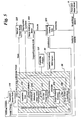
- FIG. 1 shows a schematic block diagram (e.g., flow chart) of an
implementation of a method of re-engineering a part;
- FIG. 2 shows a block diagram for generation of an editable geometry from
measurement data obtained for the part;
- FIG. 3 shows a hybrid system/process block diagram for generation of a
parametric master model from the editable geometry using KBE Part Design
Generative and Checking Rules;
- FIG. 4 shows a hybrid system/process block diagram illustrating a specific
example, for a turbine blade, of the process of Figure 3;
- FIG. 5 shows a hybrid system/process block diagram for generation of a
design analysis context model from the parametric master model, for
preparing the design analysis context model for execution of an engineering
analysis, and for executing the engineering analysis to evaluate the
parametric master model;
- FIG. 6 shows a hybrid system/process block diagram for generation of a
tooling context model from the tooling master model, for preparing the tooling
context model for execution of a manufacturing process analysis, and for
executing the manufacturing process analysis to evaluate the tooling master
model;
- FIG. 7 shows a hybrid system/process block diagram for generation of the
tooling master model from the parametric master model;
- FIG. 8 shows a process block diagram for generation, testing and
assessment of a hard tooling;
- FIG. 9 shows a turbine blade; and
- FIG. 10 shows the generation of a manufacturing context model for a
hypothetical part, the manufacture of which involves four manufacturing
steps.
-
-
A method embodiment of the invention is described generally with reference
to the flow chart shown in Figure 1. The method of re-engineering a part 10
includes generating a parametric master model 114 for part 10 from an
editable geometry 112 for part 10. As used here, the phrase "re-engineering a
part" means obtaining functional equivalents (often called "reverse
engineering") or upgrades (often called "re-engineering") for an existing part
10. Functional equivalents to an existing part 10 are parts that are structurally
(shape, material characteristics) similar to the existing part and that have
similar performance and life characteristics, whereas upgrades are parts that
have improved performance or life characteristics and may be structurally
dissimilar. Further, the phrase "existing part" means either an actual physical
part or a part for which legacy designs exist, for example 2D drawings for the
part design. Accordingly, parametric master model 114 incorporates a design
for part 10 obtained by re-engineering part 10, either to have similar or
improved performance characteristics. As indicated in Figure 3, parametric
master model 114 is generated from editable geometry 112 in a Computer
Aided Design (CAD) System (or Program) 40. An exemplary editable
geometry 112 is an editable non-parametric CAD model (also indicated by
reference numeral 112) generated using CAD System 40. Commercially
available examples of CAD software include Unigraphics sold by Unigraphics
Solutions, ProEngineer sold by Parametric Technologies, CATIA sold by
IBM/Dassault Systemes, I-DEAS sold by SDRC, and Autocad. However, the
present invention is by no means limited to any particular CAD software but
rather embraces the use of any CAD software.
-
By "editable," it is meant that the geometry 112 can be altered in its native
form, for example using the CAD software. However, as used here "non-parametric"
means that the geometry 112 does not scale with a set of
parameters but rather must be edited in a piecemeal fashion. In contrast, a
"parametric" model, such as parametric master model 114, is a representation
of part 10, for example a computer model usable within CAD software, in
which part geometry is described in terms of features, such as holes, lines,
curves, chamfers, blends, radii, well defined shapes, user defined shapes,
shapes from shape libraries, etc. and parameters associated with and
between these features. At any given time, the parameters take on specific
numerical values or relationships between parameters. Desirably, this
parametric representation of part 10 is flexible, in that part 10 is described by
a set of parameters, for example length, width, and height, all of which can
vary. Consequently, parametric master model 114 can be altered all at once
by changing the value of one or more of the parameters. Moreover, because
the model is parametric, the method applies to an entire part family. Parts
belonging to a part family differ only with respect to the values of the
parameters describing the parts or with respect to small topological changes,
for example different hole sizes or positions corresponding to different
machining steps.
-
The method further includes generating a manufacturing context model 136
from design master model 120. Manufacturing processes typically involve one
or more manufacturing steps. The desired end-product of any particular step
in the manufacturing process is a "shape" of the part being manufactured.
Manufacturing context model 136 prescribes the end result (or "shape") of
each of the manufacturing steps. In other words, the goal of each
manufacturing step is to create a part that looks like the manufacturing
context model 136 for that manufacturing step. As used here, the phrase
"context model" means a model having an associative relationship with the
underlying parametric model, such that when a parameter value is changed in
the underlying parametric model, the context model is automatically updated
to reflect this change.
-
Manufacturing context model 136 includes a number of tooling features 132.
Tooling features 132 provide tooling geometries for part features. Exemplary
tooling features for blade 10 include airfoil tooling geometry (not shown) for
forming airfoil 11, a cavity tooling geometry for forming dovetail 12, and a
platform tooling geometry for forming platform 13, as shown for example in
Figure 9. The tooling features 132, in turn, may include tooling sub-features
(also indicated by reference numeral 132 and generally referred to also as
"tooling features" 132). For example, the airfoil tooling geometry may include
pressure side and suction side tooling sub-features for forming pressure side
160 and suction side 161 of airfoil 11.
-
As indicated in Figure 1, design master model 120 includes parametric
master model 114. According to one example, design master model 120
further includes a set of geometric dimensions and tolerances (GD&Ts), a
number of CAD drawings 122 of part 10, and a set of inspection data.
Exemplary CAD drawings of part 10 include CAD drawings of a reengineered
part 10. Exemplary inspection data specify what is to be inspected on a
manufactured part to qualify the manufactured part and, as such, would be an
input to inspection systems.
-
A tooling master model 134 is created from manufacturing context model 136.
The tooling master model includes a tooling geometry 62 for part 10 and is a
parametric model. Tooling geometry 62 is obtained from tooling features 132,
for example, by applying tooling design rules that impose continuity or other
matching conditions for adjoining tooling features. According to a particular
embodiment, tooling master model 134 further includes process parameters
for each manufacturing step and footpaths. Toolpaths are included for
manufacturing processes that include one or more machining or material
addition steps. Examples of toolpaths include paths for cutters, lasers, and
drills, as well as for solid free form fabrication (for example, laser cladding)
and rapid prototyping (for example stereolithography and LOM). After addition
of tolerances (discussed in greater detail below with respect to Figure 8),
tooling master model 134 is used for generating hard tooling for
manufacturing part 10, as re-engineered. Hard tooling 400 is the physical
tooling used to form the re-engineered parts. Hard tooling may be made of
hard materials (for example, metals, such as hardened tool steels), soft
materials (for example, epoxies, low melting point alloys, wax, wood, and
aluminum), and combinations thereof.
-
In order to reengineer part 10, the method according to one embodiment
further includes obtaining data characterizing part 10 and generating editable
geometry 112 for part 10 from the data. For a second embodiment, editable
geometry 112 is obtained from legacy design information. Data acquisition is
performed, by measuring part 10 or using an existing data set characterizing
part 10. Alternatively, legacy CAD input can be used to obtain editable
geometry 112. In order to generate editable geometry 112, the data includes
geometric data for part 10. It is also useful for the data to further include
attribute data for part 10. Generally, attributes are non-geometric
characteristics, for example surface finish, material type, the presence of
coating on part 10 and density. Differentiating attribute and geometric data
are useful in that it permits geometric data to be suppressed during different
analyses, where a specific geometric feature is not necessary for the
analysis. For example, a bolt hole is typically present during a stress analysis
but omitted during a computational fluid dynamics analysis.
-
Before measuring part 10, it is desirable to determine and implement at least
one fixturing (not shown) for part 10, as indicated in Figure 1. Where more
than one measurement technique is employed, fixturing is repeated for the
different measurement techniques.
-
Digital radiography and optical scanning are useful techniques for measuring
part 10. One example of digital radiography is computer tomography (CT), for
which part 10 is scanned, for example, using an industrial CT system.
Exemplary optical scanning techniques include non-contact optical three
dimensional (3D) scanning, performed for example using a noncontact 3D
measurement system (not shown), such as a point, line, or area based
scanner, for example a light gage system combined with rotary positioning
and fixturing parts (also not shown). Other exemplary measurement
techniques include infrared radiometry and using a coordinate measuring
machine (CMM). In addition, data acquisition is not limited to a single
measurement technique. On the contrary, in one example embodiment, part
10 is scanned using computer tomography after fixturing. In this embodiment,
part 10 is also scanned using a point, line, or area based scanner. Both the
data acquired from the CT scan and from the point, line, or area based scan
are used to generate editable geometry 112, for this embodiment.
Advantageously, using multiple measurement techniques provides additional
information about part 10.
-
Because the part 10 may be damaged or worn, a CAD model of part 10 is
desirably editable to either alter specific characteristics, such as edges, or to
augment the CAD model from the data. It may further be desirable to
evaluate and adjust surface quality, particularly between adjacent features.
Surface quality includes surface smoothness, geometric continuity at surface
junctions and internal surface structure. The processes identified in block 1 in
Figure 1, namely generation of editable geometry 112 for part 10 from
measurement data 15, are illustrated in block form in Figure 2. According to
one embodiment, a non-parametric computer aided design CAD model 212
for the part 10 is generated from the geometric data. Next, non-parametric
CAD model 212 is reconstructed to obtain the editable geometry 112,
reconstruction comprising performing reverse CAD modeling. One exemplary
reverse CAD modeling process includes extracting a set of constant {u,v}
curves from surfaces 18 and then relofting surfaces 18 using the constant
{u,v} curves to obtain an editable, non-parametric CAD model (also indicated
by reference numeral 112) of part 10, for example using one of the above
noted commercial CAD systems.
-
According to a more particular embodiment, non-parametric CAD model 212
is generated as follows. First, the data are reduced to obtain a subset 16 of
the data, as shown in Figure 2. Exemplary data reduction includes removing
redundant data points to reduce the data to a manageable subset 16. The
subset is then segmented to obtain a number of feature subsets 17 of the
data, each feature subset corresponding to a feature of part 10. Exemplary
features include geometric features. For a turbine blade 10 illustrated in
Figure 9, exemplary features include an airfoil 11, a platform 12, and a
dovetail 13. Next, geometric feature extraction is performed to obtain a set of
curves and surfaces 18 from feature subsets 17. The curves and surfaces
characterize the features of part 10. Curves and surfaces 18 are imported
into a computer aided design (CAD) geometry to obtain non-parametric CAD
model 212. Alternatively, curves and surfaces 18 can be generated using the
CAD system.
-
Segmentation and geometric feature extraction are known processes and can
be performed using commercial software. For example, commercial software,
such as Surfacer®, which is supplied by EDS Corp., can be used to perform
segmentation. For turbine blade 10, one exemplary segmentation obtains
feature subsets 17 of the data corresponding to airfoil 11, platform 12, and
dovetail 13. For this example, one exemplary geometric feature extraction
extracts curves and surfaces based on the feature subsets that characterize
airfoil 11, platform 12, and dovetail 13. Commercial software, such as
Surfacer®, can be used to perform the geometric feature extraction.
-
According to a more particular embodiment, segmentation comprises
performing functional space decomposition. Namely, the 3D Euclidean space
around a data point is functionally subdivided and assigned a bit code,
thereby facilitating decision making on adjacency and connectivity issues.
Beneficially, measuring part 10 and generating editable geometry 112 from
the measurement data permits computer modeling of existing parts that do
not have CAD designs due to the age of the parts or poor archiving.
-
Although editable geometry can be altered, for example using CAD software,
editing is performed in a piecemeal fashion. In order to obtain a flexible
representation of part 10 described by a set of parameters, for example
length, width, and height, all of which can vary, parametric master model 114
is generated from editable geometry 114, as noted above. According to a
particular embodiment, generation of parametric master model 114 includes
identifying and extracting a number of critical parameters 113 from editable
geometry 112. Exemplary critical parameters 113 include dimensions and
curvatures for part 10 and are identified, for example, by a user. The
identification is performed, for example, as a preliminary stage of the method,
prior to collection of measurement data 15 and generation of editable
geometry 112. Alternatively, the identification is performed upon examining
editable geometry 112 using a CAD system.
-
As used here, the phrase "extraction of critical parameters" 113 means
determining existing or desirable values for critical parameters 113 using
editable geometry 112. For example, when using the inventive method to
reverse engineer part 10, extraction includes determining the existing values
for these parameters. However, because part 10 may be damaged or worn,
exemplary extraction of existing values includes extrapolation of the values
obtained from editable geometry. Alternatively, when using the inventive
method to reengineer part 10, extraction includes both determination of the
existing values of critical parameters 10 (including extrapolation of the values
obtained from editable geometry for a worn or damaged part 10) and applying
engineering knowledge to improve the existing values obtained from editable
geometry 112.
-
According to a more particular embodiment, critical parameters 113 are
extracted as shown in Figure 3. A set of knowledge based engineering (KBE)
part design generative rules 116 are applied to editable geometry 112, which
is stored in CAD Program 40, to obtain parametric master model 114. KBE
part design generative rules 116 incorporate engineering know-how to
construct a parametric geometry for part 10 and are implemented in a
knowledge-based environment 118, for example using EDS's Knowledge
Fusion, which is a knowledge based engineering module for the Unigraphics
environment, or using Intent Knowledge Station, which is supplied by Heidi
Corp. Although knowledge based environment 118 is illustrated in Figure 3
as being external to CAD program 40, knowledge based environments can be
either internal or external to a CAD Program, and the invention encompasses
both internal and external knowledge based environment 118.
-
Exemplary KBE part design generative rules 116 specify the relationships
between the critical parameters 113 and other attributes of editable geometry
112. Moreover, exemplary part design generative rules 116 include
geometric and non-geometric engineering rules. For example, a geometric
rule is a desired length to width ratio for airfoil 11. One exemplary non-geometric
rule is an estimated number of airfoils per blade row based upon
empirical data and thrust, flow and efficiency requirements. Another
exemplary non-geometric rule is to consider material thermal stress limits as
they relate to the weight and strength of the material. The codes underlying
KBE part design generative rules 116 may be executed, for example, in a
spreadsheet or using simulation code. Values can also be obtained by
searching a database, for example a material database. According to a
particular embodiment, KBE part design generative rules 116 are validated
based on actual measured parts 10. In this manner, Knowledge Based
Environment 118 controls creation of the parametric geometry in CAD
Program 40 for part 10 by calling functions in CAD program 40. Beneficially,
KBE part design generative rules 116 capture the engineering know-how of
engineers with considerable experience for the part family, thereby reducing
the burden of the reverse and reengineering processes on these experienced
engineers.
-
In order to ensure that parametric master model 114 satisfies a number of
functional and manufacturability requirements, a set of KBE part design
checking rules 117 is applied to parametric master model 114. For blade 10,
exemplary functional and manufacturability requirements include a calculated
stress below maximum stress criteria and a selected fillet radius larger than
minimum fillet radii required for manufacturing. However, the functional and
manufacturability requirements vary based on the part 10 being reengineered.
More particularly, KBE part design checking rules 117 are
implemented in Knowledge Based Environment 118, as indicated in Figure 3.
Exemplary checking rules involve running an analysis 121 to evaluate
parametric master model 114. Databases 50 storing operating conditions and
other data necessary for running analysis 121 are accessed via a Linked
Model Environment (LME) 30, as indicated in Figure 3.
-
Figure 4 illustrates one exemplary application of KBE part design generative
and checking rules 116, 117. For blade 10, one exemplary KBE part design
generative rule 116 is that angles at a leading edge 21 and a trailing edge 22
of airfoil 11 generate the profile of airfoil 11 for each streamline. For blade 10,
one exemplary KBE part design checking rule 117 is that a region of part 10,
for example leading edge 21, has to withstand a certain stress under load.
Application of the KBE part design checking rule 117 triggers a stress
analysis 121 via LME 30. Performing stress analysis 121 includes meshing
parametric geometry 114, applying boundary conditions, executing a stress
analysis code, and determining whether the peak stress on leading edge 21
satisfies the KBE part design checking rule 117. If not, a number of corrective
measures can be employed. For example, a design change is made or the
parametric geometry is modified. According to one embodiment, parametric
master model 114 is revised and stress analysis 121 is repeated one or more
times, until the results of stress analysis 121 are satisfactory. Alternatively,
revision of parametric master model 114 and repetition of stress analysis 121
are repeated a predetermined number of times and the iteration providing the
most satisfactory stress analysis results is selected.
-
Just as in designing a new part, it is useful to perform one or more
engineering analyses (also indicated by reference numeral 121) to reengineer
part 10. Examples of engineering analyses include stress, heat
transfer, fluid dynamic, and combustion analyses. According to a particular
embodiment, the method further includes creating at least one design
analysis context model 150 for performing an engineering analysis 121. As
shown in Figure 5, design analysis context model 150 is created in linked
model environment 30. Advantageously because design analysis context
model is created in LME 30, it is automatically updated when changes to
parametric master model 114 are made. By way of background, a linked
model environment (LME) is a methodology that encompasses using
commercial or proprietary code in a manner that is seamless to the end user.
More particularly, a typical LME links a geometry stored in a CAD Program to
an external analysis code. One example of a typical LME is a C program that
takes a Unigraphics context model for finite element analysis, runs the
context model through ICEM to create a meshed ANSYS input file, and then
runs ANSYS to generate the results. Exemplary LME's include an interface, a
script, a program, and a collection of programs.
-
As shown in Figure 5, the design analysis context model 150 includes an
associative copy 115 derived from parametric master model 114. Associative
copy 115 is configured for performing engineering analysis 121.
"Associative," as used herein, means that there exists a master-slave
relationship between parametric master model 114 and associative copy 115.
In other words, parametric master model 114 is abstracted to a level of detail
necessary to perform the engineering analysis (e.g., the necessary detail may
comprise only one specific portion of part 10). For example, when modeling
blade 10, if a specific portion of blade 10 (e.g., airfoil 11 or leading edge 21) is
needed for the engineering analysis, it is abstracted from parametric master
model 114 into associative copy 115. Because of the master-slave
relationship, associative copy 115 is synchronized to parametric master
model 114. For example, changes to parametric master model 114 are
reflected in associative copy 115. According to a more particular
embodiment, context model 150 is linked to parametric master model 114 via
an assembly file.
-
In order to perform the engineering analysis, context model 150 must be
compatible with an engineering analysis program 121. Typical engineering
analysis programs, for example, provide algorithms for the solution of
mechanical stress, heat transfer, modal analysis, buckling, and computational
fluid dynamics problems, and examples include, but are not limited to,
ANSYS, ABAQUS and Star-CD™. To render context model 150 compatible
with engineering analysis program 121, context model 150 is created as
shown in Figure 5, according to a more particular embodiment. As indicated
in Figure 5, associative copy 115 is oriented and defeatured using a number
of analysis code guidelines to obtain a defeatured design model 216. For
example, engineering analysis 121 may require rotation of associative copy
115 by ninety degrees, as shown in Figure 5. Defeaturing is performed to
obtain the subset of associative copy 115 necessary to run engineering
analysis 121, while removing portions of associative copy 115 that are not
needed for executing engineering analysis 121.
-
To simplify meshing for engineering analysis 121, defeatured design model
216 is chunked using the analysis code guidelines to obtain a chunked design
model 217. "Meshing," as used herein, means subdividing a parametric
shape into pieces small enough to allow the field quantities of interest to be
approximated by using polynomials, for example. As used here, the term
meshing includes both "meshing" used in finite element analysis (FEA)
programs and "gridding" used in computational fluid dynamics (CFD)
programs. Another term used for meshing in the art is "discretization."
-
"Chunking," as used herein, means subdividing defeatured design model 216
into a collection of simple shapes (for example six-sided volumes) where the
boolean sum of the simple shapes make up the original shape and where
each shape contains the full information of the parent geometry. It will be
appreciated by one of ordinary skill in the art that the spatial relationship
between the geometries of parametric master model 114 and the simple
shapes of chunked design model 217 is retained by using a method of
assembly functionality. Assembly functionality, as used herein, means the
ability of a CAD system to handle spatial relationships between parts. A
system that offers such functionality, for example, is Unigraphics™ sold by
Unigraphics Solutions.
-
To obtain a design analysis geometry 218 for performing engineering analysis
121, surface and boundary extraction is performed on chunked design model
217 using the analysis code guidelines. Design analysis geometry 218 is
tagged to obtain design analysis context model 150. Tagging is performed to
accommodate typical engineering analysis programs, which require unique
identifiers ("tags") of topological entities (e.g., solid bodies, faces, edges, etc.)
Typically, the tags are names or name-value pairs, where the names and
values will have some meaning for the engineering analysis program. For
example, a name titled "Airfoil_UIP" may be used to tag a chunked portion of
an airfoil solid where the engineering analysis code needs to apply a different
mesh seed. A name-value pair, for example, may be "temp=1000" which
applies to a region where the engineering analysis code needs to apply a
temperature boundary condition with a value of 1000.
-
More particularly, the orientation, defeaturing, chunking, surface and
boundary extraction, and tagging are performed within LME 30, as indicated
in Figure 5.
-
The inventive method according to a particular embodiment, further includes
preparing design analysis context model 150 for performance of the
engineering analysis, as follows. Design analysis context model 150 is
meshed using the analysis code guidelines to obtain a meshed design model
221, as shown in Figure 5. Exemplary analysis code guidelines provide a
user with recommendations for mesh seeds based on the resolution of the
model, in view of features such as holes, fillets, and other features that may
cause problems with meshing. Exemplary analysis code guidelines also
provide the user with suggested modifications to previous chunking and
defeaturing based on previous analyses. More particularly, translation scripts
of engineering analysis programs, such as ANSYS, ABAQUS and STAR-CD™,
perform the meshing, that is they tell the engineering analysis program
how to mesh the model, as well as how to apply boundary conditions and
loads.
-
By way of background, a script is a collection of commands in an ASCII (or
text) file, interpreted by an operating system (for example, HP-UX or Windows
2000) or by a particular program (Unigraphics, ANSYS, etc) to automate a
sequence of events that will be performed repeatedly. For example, an
exemplary ANSYS script opens a meshed model from ICEM (name supplied
by the user can be set for each run of the script), applies boundary conditions
to particular tagged regions in the meshed model (supplied in an ASCII file
generated by KBE rules), runs the analysis, and returns a predetermined set
of results in a particular format to an output file.
-
As shown in Figure 5, a number of boundary conditions are mapped onto
meshed design model 221 using the analysis code guidelines to obtain a
design analysis model 222. For example, the translation scripts perform the
mapping. Exemplary boundary conditions are obtained from operating
conditions, for example pressures, temperatures, and loads for blade 10.
More particularly, operating conditions such as pressures and temperatures
may need to be averaged, interpolated, or extrapolated to obtain the
boundary conditions, depending on the number of node points and the fidelity
of the operational data. In addition, boundary conditions may include
operational data such as RPM, which is an input to generative rules for the
disk size of compressor and turbine disks, for example. Other exemplary
boundary conditions are obtained from the material type and microstructure
for part 10. Still other exemplary boundary conditions include analysis
results, for example results from previously performed engineering analyses.
Boundary conditions, such as the material of part 10, are stored for example
in a product data management (PDM) system 20, for example iMAN from
Unigraphics and eMatrix. The boundary conditions are mapped, according to
one embodiment, by linking the PDM system 20 through a linked model
environment (LME) 30, such as the LME methodology available through
Unigraphics Wave. Moreover, the preparation may further include
identification (for example, using the translation scripts) of standard shapes
and loadings, for which closed form engineering solutions are known.
-
The inventive method according to a more particular embodiment, further
includes performing the engineering analysis on design analysis model 222 to
obtain engineering analysis data 223. More particularly, an engineering
analysis code is executed using the design analysis model 222 and a number
of convergence criteria. Convergence criteria determine if all of the user-specified
constraints, the equation solvers are trending toward a solution.
Exemplary engineering analyses include thermal and stress analyses and are
performed, for example, by applying a finite element or a finite difference
method, thereby generating a data file. Typical data file content includes
values of stresses, displacements, pressures, temperatures, or velocities. For
example, the engineering analysis code is stored on a simulation engine,
which is a server that provides engineering analysis through generalized
interfaces defined by wrapping the engineering analysis codes.
-
The engineering analysis data 223 is desirably used to revise the design
underlying parametric master model 114, in order to improve its performance.
For example, the engineering analysis data are evaluated and, if deemed
unsatisfactory, the design for part 10, and hence parametric master model
114, are modified using a set of redesign goals, as indicated in Figure 5. The
redesign goals vary based on implementation. However, exemplary redesign
goals for blade 10 include cooling efficiency, reduced weight, and lower peak
stress. In contrast, if the results of the evaluation are found to be satisfactory,
parametric master model 114 is not altered, as indicated in Figure 5.
Evaluation of the engineering analysis data 223 is performed by an
automated computer program (e.g., iSIGHT™ by Engineous Software or
ModelCenter™ by Phoenix Integration) or alternatively by an operator. If the
performance is deemed unsatisfactory, the automated computer program or
operator revises the design for part 10 by modifying the geometric parameters
characterizing part 10. This in turn updates parametric master model 114.
Further, because design analysis context model 150 includes an associative
copy 115 of parametric master model 114, design analysis context model 150
is updated. Accordingly, it is unnecessary to repeat the orientation, chunking,
performance of surface and boundary extraction, and tagging, as indicated in
Figure 5 for the second and all subsequent iterations, provided any changes
made to the design are on a small parametric scale. However, for topological
changes to the design or for changes to the design on a large parametric
scale, such that applying the same chunking through tagging would create
poor results, the scripts are desirably revisited to account for changes in the
meshing strategy. The method encompasses both possibilities.
-
After updating parametric master model 114 (and by association, design
analysis context model 150), it is useful to repeat engineering analysis 121, to
determine whether performance is improved. Repetition of engineering
analysis 121 involves, for example, meshing and mapping of boundary
conditions to obtain design analysis model 222, as discussed above with
respect to the original performance of engineering analysis 121. The
engineering analysis code is then executed to obtain a new set of engineering
analysis data, as discussed above. It will be appreciated that "repetition" of
engineering analysis 121 for design changes on a small parametric scale
involves the execution of existing scripts created in the meshing, mapping,
and execution steps discussed above. These scripts do not need to be
recreated in subsequent iterations because of their dependency on the
tagged geometry initially developed in the creation of design analysis context
model 150. Alternatively, for topological and large parameter scale design
changes, "repetition" of engineering analysis 121 includes revisiting the
scripts to account for changes in the meshing strategy.
-
In one embodiment, parametric master model 114 is revised and engineering
analysis 121 is repeated until satisfactory results are obtained. In an
alternative embodiment, parametric master model 114 is revised, and
engineering analysis 121 is repeated, a given number of times, for example
five (5) times, to accommodate time or computational constraints. For this
embodiment, the optimal results for a given set of criteria are selected from
the iterations, for example by the automated computer program or operator.
More generally, the pre-determined number of iterations may be one or more,
depending on implementation.
-
According to a more particular embodiment, at least one additional context
model (not shown) is generated and an additional engineering analysis is
performed to further evaluate the performance of the design. For example,
after satisfactory completion of a thermal analysis, a stress analysis is
performed. The additional context model is generated and the additional
engineering analysis is performed in the manner described above with
respect to context model 150 and shown in Figure 5. For this embodiment,
parametric master model 114 is revised and the additional engineering
analysis is repeated, as discussed above with respect to engineering analysis
121, to obtain a satisfactory design (and corresponding parametric master
model 114). A satisfactory design for blade 10, for example, meets all
imposed thermal, stress, and displacement constraints. In the alternative
embodiment, parametric master model 114 is revised, and the additional
engineering analysis is repeated a given number of times, and the optimal
design for part 10 is selected from the iterations.
-
As noted above, parametric master model 114 desirably provides a part
design for the entire part family of part 10. Thus, by changing the values of
the parameters, designs for different members of the part family are provided,
without repetition of the reengineering process.
-
After parametric master model 114 has been finalized, geometric dimensions
and tolerances (GD&Ts or "geometric tolerances") are desirably added to
parametric master model 114 in preparation for manufacturing. GD&Ts
specify the maximum allowable deviation from the nominal size and shape
specified by the part design underlying parametric master model 114. In one
embodiment, the inventive method further includes processing parametric
master model 114 with producibility data from a producibility database 240 to
add GD&Ts to parametric master model 114, as shown in Figure 7. For
example, parametric master model 114 is linked to producibility database 240
via a Wrapper 241. Wrappers are application interface codes that wrap
around an analysis program, and one example is a Federated Intelligent
Product Environment (FIPER) wrapper. Exemplary producibility data include
process capability limits, for example, for surface flatness for a casting
operation. For this embodiment, design master model 120 includes
parametric master model 114 with geometric dimensions and tolerances.
-
After design master model 120 has been generated, manufacturing context
model 136 is generated. As noted above, manufacturing context model 136
prescribes the end result (or "shape") of the part for each of the
manufacturing steps and includes tooling features 132. Manufacturing steps
include all types of manufacturing processes, for example forming steps,
material addition steps (for example, deposition), material removal steps (for
example, machining, EDM, and ECM), rapid prototyping steps (for example,
stereolithography), and finishing steps (for example, shot peening or laser
peening). Exemplary machining steps include tool path generation. The
tooling features are parametric geometries for part features. Exemplary
tooling features for blade 10 include airfoil tooling geometry (not shown) for
forming airfoil 11, a cavity tooling geometry for forming dovetail 12, and a
platform tooling geometry for forming platform 13. An exemplary airfoil tooling
geometry includes pressure side and suction side tooling sub-features (not
shown) for forming pressure side 160 and suction side 161 of airfoil 11.
More particularly, manufacturing context model 136 is generated as indicated
in Figure 7, according to a particular embodiment. As shown in Figure 7,
parametric master model 114 with geometric dimensions and tolerances is
oriented to obtain an oriented GD&T model 133. As used here, the term
"orient" refers to spatial orientation. For the embodiment shown in Figure 7,
the orientation is performed in a CAD Program 42. CAD Programs 40, 42 are
identified by distinct reference numbers to signify that they are being used in
the generation of parametric master model 114 and tooling master model
134, respectively. However, the same CAD Program can be used to
generate parametric master model 114 and tooling master model 134.
-
Accordingly, the use of two reference numbers should not be understood to
require two CAD Programs but rather to indicate the different processes being
performed therein.
-
A number of manufacturing design rules 242 are applied to oriented GD&T
model 133 to obtain manufacturing context model 136. Manufacturing design
rules 242 include tooling design rules for forming steps and tool path
generation rules for machining steps and represent the experience of tooling
designers for part 10 and more generally, for the part family. Exemplary
tooling design rules 242 include formulas and other relationships between
parameter values. More complex tooling design rules 242 involve execution
of tooling geometry code 60. As shown in Figure 7, execution of tooling
geometry code 60 is performed via a tooling linked model environment (LME)
244. More particularly, manufacturing design rules 242 are implemented in a
tooling knowledge based environment 243. Beneficially, the manufacturing
design rules 242 capture the tooling design know-how of experienced
engineers, thereby reducing the demands of the tooling design process on
such engineers. For the embodiment shown in Figure 7, manufacturing
context model 136 is generated in CAD Program 42. Although tooling
knowledge based environment 243 is shown in Figure 7 as being separate
from CAD Program 42, knowledge based environments can be either internal
or external to CAD Programs and the invention covers tooling knowledge
based environments 243 internal or external to CAD Program 42. For
example, Knowledge Station is an external knowledge based environment,
whereas Knowledge Fusion is an internal knowledge based engineering
module for the Unigraphics CAD program.
-
In the event that only one manufacturing step will be used, such as for a
simple part (e.g., injection molded plastic screws), manufacturing context
model 136 is generated in this manner. However, for more complex parts,
such as blade 10, several manufacturing steps may be performed, for
example to form airfoil 11, platform 12, and dovetail 13 and to machine holes,
for example radial cooling holes (not shown) in airfoil 11. For illustrative
purposes only, Figure 10 shows the generation of a manufacturing context
model 136 for a hypothetical part 10, the manufacture of which involves two
forming steps and two machining steps. Where more than one manufacturing
step will be employed, generation of manufacturing context model 136 further
includes orienting manufacturing context model to obtain oriented GD&T
model 133, as indicated in Figure 7 and illustrated in Figure 10. The
manufacturing design rules 242 for an additional manufacturing step are
applied to oriented GD&T model 133 to generate manufacturing context
model 136 encompassing the additional manufacturing step, as shown in
Figure 10. This process is repeated for each of the additional manufacturing
steps to generate manufacturing context model 136 encompassing the
additional manufacturing steps. As indicated in Figure 10, manufacturing
context model 136 prescribes the shape of the part being manufactured and
specifies the tooling features 132 for each of the manufacturing steps
performed during the manufacturing process.
-
In addition to forming steps, such as forging, the manufacture of part 10 may
include one or more machining steps, for example lasing a number of holes in
part 10. Accordingly, for another embodiment of the inventive method,
generation of manufacturing context model 134 further includes orienting
manufacturing context model 136 to obtain the oriented GD&T model and
applying the tool path generation rules 242 for a machining step to generate
manufacturing context model 136 encompassing the machining steps, as
illustrated in Figure 10. This process is repeated for each of the machining
steps to generate manufacturing context model 136 encompassing the
machining steps. Tooling master model 134 for this embodiment further
includes tool paths and process parameters for performing the machining
steps, the tool paths being derived from manufacturing context model 136.
-
As noted above, manufacturing context model 136 includes tooling features
132, which provide tooling geometries for part features. However, to create
the tooling (for example, dies), a tooling geometry 62 is required. Tooling
geometry 62 is a model of the tooling for the one or more manufacturing
steps. For the case of a two forming step manufacturing process, for
example, tooling geometry 62 includes models for a first and a second
tooling, with each model derived from tooling features 132 for the respective
forming step. More particularly, tooling master model 134, which includes
tooling geometry 62, is generated by applying tooling design rules 242 to
manufacturing context model 136, to derive tooling geometry 62 from tooling
features 132. For the exemplary embodiment shown in Figure 7, tooling
master model 134 is generated in CAD Program 42 by applying tooling
design rules 242 using tooling knowledge based environment 243.
Exemplary tooling design rules 242 impose continuity or other matching
conditions for adjoining tooling features 132 to form tooling geometry 62 for
part 10.
-
In addition to tooling geometry 62, tooling master model 134 according to a
particular embodiment further includes process parameters for each
manufacturing step and toolpaths. More particularly, process parameters are
included as attributes in tooling master model 134 for one embodiment and
are stored in a linked attribute file in tooling PDM system 320 for another
embodiment. As explained above, toolpaths are included for manufacturing
processes that include one or more machining steps. For example, if the
manufacturing step is a forging, an exemplary tooling geometry 62 includes a
die geometry (derived from manufacturing context model 136) and an
exemplary tooling master model 134 further includes process parameters,
such as press speed, temperature, and load. If the manufacturing step is a
machining operation, tooling master model 134 includes toolpaths (geometry)
and process parameters, such as cutter speed, type of cutter, and feedrate.
-
In order to evaluate tooling master model 134, it is useful to perform one or
more manufacturing process analyses, such as a forging process simulation
for a forged part, such as an engine disk or a compressor blade. The
manufacturing process analysis is used to evaluate tooling geometry 62 to
verify that the manufacturing step yields the expected output. According to a
particular embodiment, the method further includes creating at least one
tooling context model 141. The tooling context model 141 includes an
associative copy 142 of tooling master model 134. The associative copy 142
is configured for performing a manufacturing process analysis 321. The term
"associative," as explained above, means that there exists a master-slave
relationship between tooling master model 134 and its associative copy 142,
such that changes to tooling master model 134 are reflected in associative
copy 142.
-
An exemplary creation of tooling context model 141 is illustrated in Figure 6
and is similar to the creation of design analysis context model 150 discussed
above. As shown in Figure 5, tooling context model 141 is created in tooling
linked model environment (tooling LME) 300. Advantageously because
tooling context model 141 is created using LME methodology, it is
automatically updated when changes to tooling master model 134 are made.
Associative copy 142 is oriented and defeatured using a set of analysis code
guidelines to obtain a defeatured tooling model 143. To simplify meshing for
performing manufacturing process analysis 321, defeatured tooling model
143 is chunked using the analysis code guidelines to obtain a chunked tooling
model 144. To obtain a tooling analysis geometry 145 for performing
manufacturing process analysis 321, surface and boundary extraction is
performed on chunked tooling model 144 using the analysis code guidelines.
Tooling analysis geometry 145 is tagged to accommodate typical engineering
analysis programs, which require unique identifiers ("tags") of topological
entities (e.g., solid bodies, faces, edges, etc.), thereby generating tooling
context model 141.
-
According to a particular embodiment, the method further includes preparing
tooling context model 141 for performance of the manufacturing process
analysis, as follows. Tooling context model 141 is meshed using the analysis
code guidelines to obtain a meshed tooling model 146. As shown in Figure
6, a number of boundary conditions, for example the contact conditions
between pieces of the die for forging, are mapped onto meshed tooling model
146 using the analysis code guidelines, to obtain a tooling analysis model
147. Boundary conditions are stored, for example in a tooling product data
management (PDM) system 320, as indicated in Figure 6. Tooling PDM
system 320 may be PDM system 20 or may be an independent PDM system.
The boundary conditions are mapped, according to one embodiment, by
linking tooling PDM system 320 through tooling LME 300.
-
After tooling analysis model 147 is obtained, manufacturing process analysis
321 is performed thereon to obtain tooling analysis data 323, as indicated in
Figure 6. More particularly, a manufacturing process analysis code is
executed using tooling analysis model 147 and a number of convergence
criteria and process parameters. Exemplary process parameters include
clamping forces, press speed, and temperature, and are stored for example in
tooling PDM system 320. Exemplary manufacturing process analyses 321
are performed using finite element methodology and include simulation of the
manufacturing process to generate data for stresses, deflections,
temperatures, and strain rates for the part being manufactured and for the
tooling, for example the die.
-
Tooling analysis data 323 are then used to evaluate tooling geometry 62 of
tooling master model 134, according to a particular embodiment. More
particularly, tooling analysis data 323 is evaluated, for example, by an
automated computer program or operator. If tooling analysis data 323 is
deemed unsatisfactory, tooling geometry 62, and hence tooling master model
134, is modified using a set of manufacturing goals and taking into account
tooling design tradeoffs, as indicated in Figure 6. The manufacturing goals
and tooling design tradeoffs vary based on implementation. Typical
exemplary tooling goals for blade 10 include tooling service life and material
used for tooling, and exemplary tooling design tradeoffs include cost, time to
make tooling, and set-up time in production. In contrast, if the results of the
evaluation are found to be satisfactory, tooling master model 134 is not
altered, as indicated in Figure 6.
-
More particularly, if tooling analysis data 323 is deemed unsatisfactory, the
automated computer program or operator revises tooling geometry 62 by
modifying the geometric parameters characterizing the constituent tooling
features. This in turn updates tooling master model 134, which automatically
updates tooling context model 141 because of the associative relationship
between tooling master model 134 and tooling context model 141.
Accordingly, the orientation through tagging, steps need not be repeated for
small parametric scale tooling modifications, as indicated in Figure 6.
-
After updating tooling master model 134 (and by association, tooling context
model 141), it is useful to repeat manufacturing process analysis 321, to
determine whether performance is improved. Repetition of manufacturing
process analysis 321 is indicated in Figure 6 and is performed in the same
manner as repetition of engineering analysis 121, as discussed above.
-
In one embodiment, tooling master model 134 is revised and manufacturing
process analysis 321 is repeated until a satisfactory tooling geometry 62 (and
corresponding tooling master model 134) is achieved. Alternatively, revision
of tooling master model 134 and subsequent repetition of manufacturing
process analysis 321 are performed a predetermined number of (one or
more, for example five) times. For the latter embodiment, the optimal tooling
geometry for part 10 is selected from the iterations, for example by the
automated computer program or operator based on the manufacturing goals
and tooling design tradeoffs. If no additional manufacturing process analyses
are to be performed, tooling master model 134 corresponds to the optimal
tooling geometry.
-
According to a more particular embodiment, at least one additional tooling
context model (not shown) is generated and an additional manufacturing
process analysis is performed to further evaluate the performance of tooling
geometry 62. The additional tooling context model is generated and the
additional manufacturing process analysis is performed in the manner
described above with respect to tooling context model 141 and shown in
Figure 6. For this embodiment, tooling master model 134 is revised and the
additional manufacturing process analysis is repeated, as discussed above
with respect to manufacturing process analysis 321, to obtain a satisfactory
tooling geometry 62 (and corresponding tooling master model 134). In the
alternative embodiment, tooling master model 134 is revised, and the
additional manufacturing process analysis is repeated a given number of
times, and the optimal tooling geometry 62 is selected from the iterations.
-
Beneficially, because tooling master model 134 is a parametric model, it
provides the tooling geometry for the entire part family. Thus, by changing
the values of the parameters, tooling geometries for different members of the
part family are automatically provided.
-
After generation of tooling master model 134, geometric dimensions and
tolerances (GD&Ts or "geometric tolerances") are desirably added to tooling
master model 134 in preparation for hard tooling (i.e., creation of the dies,
molds, etc for manufacturing part 10, as reengineered). In one embodiment,
GD&Ts are added to tooling master model 134 using CAD system 42, as
shown in Figure 8. For this embodiment, tooling master model 134 further
includes a number of CAD drawings of a hard tooling 400, and a set of
inspection data. Exemplary inspection data include geometry inspection data
for hard tooling 400 to verify that the hard tooling created is what was
designed. Tooling master model 134 is then used to generate hard tooling
400, using conventional hard tooling manufacturing techniques which vary
based on implementation.
-
In order to evaluate hard tooling 400, it is useful to manufacture and inspect
one or more test parts 410 using hard tooling 400, as indicated in Figure 8.
Prior to manufacturing test part 410, fixturing and set up (or preprocessing
work) is performed, as indicated in Figure 8. According to the embodiment
shown in Figure 8, the inventive method further includes manufacturing at
least one test part 410 using hard tooling 400 and using process parameters.
Process parameters are operating conditions that are set when manufacturing
a part, for example machine parameters such as cutter speed, feed rates,
press load, or general parameters such as temperature. Test part 410 is
inspected, for example using one or more of the following inspection
techniques: digital radiography (such as computer tomography), optical
scanning (such as non-contact optical three dimensional scanning performed
using a non-contact 3D measurement system, for example a point, line, or
area based scanner), infrared radiometry, and using a coordinate measuring
machine (CMM). Measurement data 420 obtained from the inspection is
assessed by an engineer or an automated computer program to determine
whether tooling master model 134 produces acceptable test parts 410, based
on the engineering criteria for part 10. If test parts 410 are acceptable,
tooling master model 134 and hard tooling 400 are used to manufacture parts
10. However, if test parts 410 do not satisfy the engineering criteria, tooling
master model 134 is revised and reevaluated one or more times, until test
parts 410 satisfy the engineering criteria for part 10.
-
Desirably, tooling master model 134 is used to manufacture parts having the
same or improved functionality as original part 10, depending on the
objectives of the re-engineering method. To this end, a method of
manufacturing embodiment is disclosed. The method of manufacturing
includes generating parametric master model 114 from editable geometry
112, generating manufacturing context model 136 from parametric master
model 114, and creating tooling master model 134 from manufacturing
context model 136, as discussed above generally with respect to Figure 1,
and more particularly with respect to Figures 3-7. The method of
manufacturing further includes generating hard tooling 400 using tooling
master model 134, for example as shown in Figure 8, and further includes
manufacturing at least one part using hard tooling 400 and the process
parameters. As discussed above, exemplary process parameters include
clamping forces, press speed, and temperature.
-
In one embodiment, editable geometry 112 is generated from data
characterizing part 10, for example measurement data. In another
embodiment, editable geometry 112 is generated from legacy part designs.
-
In a particular embodiment, parametric master model 114 is generated using
KBE part design generative and checking rules 116, 117, as discussed above
with respect to Figures 3 and 4. For this embodiment, at least one design
analysis context model 150 is created, for example in LME 30, for evaluating
parametric master model 114.
-
To add geometric dimensions and tolerances GD&Ts, parametric master
model 114 is processed with producibility data from producibility database
240, as discussed above with respect to Figure 7. The addition of GD&Ts is
performed either in CAD system 40 or in tooling CAD system 42, and these
CAD systems may be the same or a different CAD system. For this
embodiment, manufacturing context model 136 is generated as discussed
above with respect to Figure 7. More particularly, manufacturing context
model 136 is generated for a number of manufacturing steps.
-
Tooling master model 134 is then created by applying tooling design rules
242 to manufacturing context model 136, according to a more particular
embodiment. Further to evaluate tooling master model 134, the method more
particularly further includes creating at least one tooling context model 141.
-
A system 100 embodiment is described with reference to Figures 1, 3, 4, and
7. As indicated in Figure 1, the system 100 for engineering part 10 includes a
part design master model module 110, which is configured to generate
parametric master model 114 from editable geometry 112. System 100
further includes a tooling master model module 130, which is configured to
receive parametric master model 114, to generate manufacturing context
model 136 from parametric master model, and to create tooling master model
134 from manufacturing context model 134. The phrase "configured to" as
used herein means that part design master model module 110 and tooling
master model module 130 are equipped with a combination of hardware and
software for performing the tasks of the invention, as will be understood by
those skilled in the art. For example, part design and tooling master model
modules 110, 130 include a computer equipped with software for performing
their respective tasks. The present invention is not limited to any particular
computer for performing the processing tasks of the invention. Rather, the
term "computer" is intended to denote any machine capable of performing the
calculations, or computations, necessary to perform the tasks of the invention,
for example by accepting a structured input and processing the input in
accordance with prescribed rules to produce an output.
-
As shown in Figure 4, part design master model module 110 according to a
particular embodiment includes CAD system 40 configured to generate
parametric master model 114 from editable geometry 112, and knowledge
based environment 118 is configured to apply KBE part design generative
rules to editable geometry 112 to obtain parametric master model 114.
Knowledge based environment 118 is further configured to apply KBE part
design checking rules to parametric master model 114 to ensure that it
satisfies functional and manufacturability requirements. As discussed above,
knowledge based environment 118 can be either internal or external to CAD
system 40. More particularly, CAD system 40 is further configured to
generate editable geometry 112 from data characterizing part 10, such as the
measurement data discussed above.
-
According to a more particular embodiment, part design master model
module 110 further includes linked model environment LME 30 configured for
creating at least one design analysis context model 150, and an engineering
analysis code 121 for performing the engineering analysis. As shown, for
example in Figure 5, engineering analysis 121 is linked through LME 30.
More particularly, part design master model module 110 further includes part
data management PDM system 20, which is configured to store operating
condition data for deriving the boundary conditions. More particularly, PDM
20 is further configured to store all other product associated data and revision
history. LME 30 is configured to link PDM system 20 to meshed design
model 221, to map the boundary conditions onto meshed design model 221,
as indicated in Figure 5. To add geometric tolerances to parametric master
model 114, CAD system 40 is further configured to process parametric master
model 114 with producibility data. Although Figure 7 shows the latter
processing step being performed in tooling CAD system 42, geometric
dimensions and tolerances can be added using either CAD system 40 or
tooling CAD system 42. Moreover, as discussed above CAD system 40 and
tooling CAD system 42 may be either the same or different CAD systems.
-
As shown in Figure 7, tooling master model module 130, according to a
particular embodiment, includes tooling CAD system 42 configured to receive
parametric master model 114, to orient parametric master model 114 after
processing with geometric dimensions and tolerances to obtain oriented
GD&T model 133, and to generate manufacturing context model 136 from
parametric master model. Tooling master model module 130 further includes
tooling knowledge based environment 243 configured to apply manufacturing
design rules 242 to oriented GD&T model 133 to obtain manufacturing
context model 136. As discussed above, manufacturing rules include tooling
design rules and path generation rules.
-
Complex manufacturing processes may employ more than one forming step
and may include one or more machining steps. Accordingly, tooling CAD
system 42 is desirably configured to generate manufacturing context model
for a number of manufacturing steps. For this particular embodiment, CAD
system 42 is further configured to orient manufacturing context model 136 to
obtain oriented GD&T model 133, and tooling knowledge based environment
243 is further configured to apply manufacturing design rules 242 to oriented
GD&T model 133 to generate the manufacturing context model 136, as
shown in Figure 7.
-
To generate tooling master model 134 from manufacturing context model
136, tooling knowledge based environment 243 is further configured to apply
the tooling design rules to manufacturing context model 136. For this
embodiment, tooling CAD system 42 is further configured to derive tooling
geometry 62 from manufacturing context model 136 using the tooling design
rules.
-
In order to evaluate tooling master model 134, tooling master model module
130, according to the embodiment shown in Figure 6, further includes tooling
linked model environment (tooling LME) 300 configured for creating at least
one tooling context model 141, and a manufacturing process analysis code
321 for performing the manufacturing process analysis. As shown in Figure
6, manufacturing process analysis 321 is linked through tooling LME 300.
More particularly, tooling master model module 130 further includes tooling
part data management PDM system 320 configured to store operating
condition data for deriving the boundary conditions and to store the process
parameters. More particularly, tooling PDM 320 is further configured to store
all other product associated data and revision history. As indicated in Figure
6, tooling LME 300 is configured to link tooling PDM system 320 to meshed
tooling model 146, to map the boundary conditions onto meshed tooling
model 146. Tooling LME 300 is further configured to link tooling PDM system
320 to manufacturing process analysis 321, to supply the process parameters
for performing the manufacturing process analysis.
-
In order to produce hard tooling 400, tooling CAD system 42 is desirably
further configured to add geometric dimensions and tolerances to tooling
master model 134, as indicated for example in Figure 8.
-
Further, to re-engineer a system or subsystem rather than a part, system 100
further includes a Product Control Structure (not shown) to layout the overall
system configuration and control changes in a top-down fashion.
-
For the sake of good order, various aspects of the invention are set out in the
following clauses:-
- 1. A method of re-engineering a part (10) comprising:
- generating a parametric master model (114) for the part (10) from an
editable geometry (112) for the part;
- generating a manufacturing context model (136) from a design master
model (120), the design master model comprising the parametric master
model (114) and the manufacturing context model comprising a plurality of
tooling features (132); and
- creating a tooling master model (134) from the manufacturing context
model (136), the tooling master model comprising a tooling geometry (62) for
the part (10).
- 2. The method of Clause 1, further comprising:
- obtaining data characterizing the part (10); and
- generating the editable geometry (112) for the part from the data.
- 3. The method of Clause 2, wherein said obtaining comprises measuring
the part (10) to obtain the data.
- 4. The method of Clause 3, wherein said measurement comprises
performing at least one of digital radiography and optical scanning.
- 5. The method of Clause 2, wherein the data comprise geometric data for
the part (10).
- 6. The method of Clause 5, wherein the data further comprise attribute
data for the part (10).
- 7. The method of Clause 5, wherein said generation of the editable
geometry (112) for the part (10) comprises:
- generating a non-parametric computer aided design (CAD) model
(212) for the part (10) from the geometric data; and
- reconstructing the non-parametric CAD model (212) to obtain the
editable geometry (112), said reconstruction comprising performing reverse
CAD modeling.
- 8. The method of Clause 7, wherein said generation of the non-parametric
CAD model (212) for the part (10) comprises:
- reducing the data to obtain a subset of the data,
- segmenting the subset to obtain a plurality of feature subsets of the
data, each feature subset corresponding to a feature (11), (12), (13) of the
part (10),
- performing geometric feature extraction to obtain a plurality of curves
and surfaces from the feature subsets, the curves and surfaces characterizing
the features (11), (12), (13) of the part (10), and
- importing the curves and surfaces into a computer aided design (CAD)
geometry to obtain the non-parametric CAD model (212).
- 9. The method of Clause 1, further comprising obtaining the editable
geometry (112) from legacy design information.
- 10. The method of Clause 1, wherein said generation of the parametric
master model comprises identifying and extracting a plurality of critical
parameters from the editable geometry (112).
- 11. The method of Clause 10, wherein said extraction of the critical
parameters comprises:
- applying a plurality of knowledge based engineering (KBE) part design
generative rules to the editable geometry (112) to obtain the parametric
master model (114), and
- applying a plurality of KBE part design checking rules to the parametric
master model (114) to ensure that the parametric master model satisfies a
plurality of functional and manufacturability requirements.
- 12. The method of Clause 1, further comprising creating at least one
design analysis context model (150), the design analysis context model
comprising an associative copy (115) of the parametric master model (114)
which is configured for performing an engineering analysis (121).
- 13. The method of Clause 12, wherein at least two design context models
(150) are created, each of the design context models being configured for
performing a different engineering analysis (121).
- 14. The method of Clause 12, further comprising preparing the design
analysis context model (150) for performance of the analysis, said preparation
comprising:
- meshing the design analysis context model (150) using the analysis
code guidelines to obtain a meshed design model (221), and
- mapping a plurality of boundary conditions onto the meshed design
model (221) using the analysis code guidelines to obtain a design analysis
model (222),
- the method further comprising:
- performing the engineering analysis on the design analysis model
(222) to obtain a plurality of engineering analysis data (223), said
performance comprising executing an engineering analysis code using the
design analysis model (222) and a plurality of convergence criteria; and
- evaluating the engineering analysis data (223) and, if the engineering
analysis data are unsatisfactory, said method still further comprising:
- modifying the parametric master model (114) using a plurality of
redesign goals, and
- repeating said performance of the engineering analysis (121) after
modifying the parametric master model (114).
- 15. The method of Clause 1, further comprising processing the parametric
master model (114) with producibility data from a producibility database 240
to add geometric dimensions and tolerances (GD&T) to the parametric master
model (114), wherein the design master model (120) comprises the
parametric master model (114) with geometric dimensions and tolerances.
- 16. The method of Clause 15, wherein said generation of the
manufacturing context model (136) comprises:
- orienting the parametric master model (114) using the geometric
dimensions and tolerances to obtain an oriented GD&T model (133); and
- applying a plurality of manufacturing design rules (242) to the oriented
GD&T model (133) to obtain the manufacturing context model (136).
- 17. The method of Clause 16, wherein said generation of the
manufacturing context model (136) further comprises:
- orienting the manufacturing context model (136) to obtain the oriented
GD&T model (133); and
- applying the manufacturing design rules (242) to the oriented GD&T
model (133) to generate the manufacturing context model (136)
encompassing at least one additional manufacturing step, wherein said
orientation and application are performed for each of the additional
manufacturing steps.
- 18. The method of Clause 16, wherein the manufacturing design rules
include a plurality of tooling design rules and wherein said creation of the
tooling master model (134) comprises applying the tooling design rules to the
manufacturing context model (136) to obtain the tooling master model (134),
wherein the tooling geometry (62) is derived from the tooling features (132) by
said application of the design rules.
- 19. The method of Clause 16, further comprising creating at least one
tooling context model (141) comprising an associative copy (142) of the
tooling master model (134) which is configured for performing a
manufacturing process analysis (321).
- 20. The method of Clause 19, wherein at least two tooling context models
(141) are created, each of the tooling context models being configured for
performing a different manufacturing process analysis (321).
- 21. The method of Clause 19, further comprising preparing the tooling
context model (141) for performance of the manufacturing process analysis
(321), said preparation comprising:
- meshing the tooling context model (141) using the analysis code
guidelines to obtain a meshed tooling model (146), and
- mapping a plurality of boundary conditions onto the meshed tooling
model (146) using the analysis code guidelines to obtain a tooling analysis
model (147),
- said method further comprising performing the manufacturing process
analysis (321) on the tooling analysis model (147) to obtain a plurality of
tooling analysis data (323), said performance comprising executing a
manufacturing process analysis code using the tooling analysis model (147),
- a plurality of convergence criteria, and a plurality of process
parameters; and
- evaluating the tooling analysis data (323) and, if the tooling analysis
data are unsatisfactory, still further comprising:
- modifying the tooling master model (134) using a plurality of
manufacturing goals tooling design tradeoffs, and
- repeating said performance of the manufacturing process analysis
(321) after modifying the tooling master model (134).
- 22. The method of Clause 16, further comprising adding a plurality of
geometric dimensions and tolerances (GD&Ts) to tooling master model (134).
- 23. The method of Clause 22, wherein the tooling master model (134)
further includes a plurality of process parameters, the method further
comprising:
- generating a hard tooling (400) using tooling master model (134) with
the geometric dimensions and tolerances;
- manufacturing at least one test part (410) using the hard tooling (400)
and using the process parameters;
- inspecting test part (410) to obtain a plurality of measurement data
(420); and
- assessing the measurement data (420) to determine whether the test
parts (410) satisfy a plurality of engineering criteria for the part (10).
- 24. A system (100) for re-engineering a part (10) comprising:
- a part design master model module (110) configured to generate a
parametric master model (114) for the part from an editable geometry (112)
for the part; and
- a tooling master model module (130) configured to receive the
parametric master model (114), to generate a manufacturing context model
(136) from the parametric master model, and to create a tooling master model
(134) from the manufacturing context model, wherein the manufacturing
context model comprises a plurality of tooling features (132) and the tooling
master model comprises a tooling geometry (62).
- 25. The system of Clause 24, wherein said part design master model
module (110) comprises:
- a computer aided design (CAD) system (40) configured to generate the
parametric master model (114) from the editable geometry (112); and
- a knowledge based engineering (KBE) environment (118) configured
to apply a plurality of knowledge based engineering (KBE) part design
generative rules to the editable geometry (112) to obtain the parametric
master model (114), and to apply a plurality of KBE part design checking
rules to the parametric master model (114) to ensure that the parametric
master model satisfies a plurality of functional and manufacturability
requirements.
- 26. The system of Clause 25, wherein said CAD system (40) is further
configured to generate the editable geometry (112) from data characterizing
the part (10).
- 27. The system of Clause 25, wherein said part design master model
module (110) further comprises:
- a linked model environment (30) configured for creating at least one
design analysis context model (150), the context model comprising an
associative copy (115) of the parametric master model (114) and being
configured for performing an engineering analysis (121); and
- an engineering analysis code (121) for performing the engineering
analysis to generate engineering analysis data (223) for evaluating the
parametric master model.
- 28. The system of Clause 27, wherein said part design master model
module (110) further comprises a part data management (PDM) system (20)
configured to store operating condition data for deriving a plurality of
boundary conditions, wherein said linked model environment (30) is
configured to link said PDM system (20) to a meshed design model (221)
obtained from the design analysis context model (150), to map the boundary
conditions onto the meshed design model.
- 29. The system of Clause 25, wherein said CAD system (40) is further
configured to process the parametric master model (114) with producibility
data to add geometric dimensions and tolerances to the parametric master
model.
- 30. The system of Clause 24, wherein said tooling master model module
(130) comprises:
- a tooling computer aided design (CAD) system (42) configured to
receive the parametric master model, to orient the parametric master model
(114) after processing with a plurality of geometric dimensions and tolerances
to obtain an oriented GD&T model (133), and to generate the manufacturing
context model (136) from the parametric master model; and
- a tooling knowledge based environment (243) configured to apply a
plurality of manufacturing design rules (242) to the oriented GD&T model
(133) to obtain the manufacturing context model (136).
- 31. The system of Clause 30, wherein said tooling CAD system (42) is
further configured to generate the manufacturing context model (136) for a
plurality of manufacturing steps.
- 32. The system of Clause 31, wherein the manufacturing design rules
include a plurality of tooling design rules, wherein said tooling knowledge
based environment (243) is further configured to apply the tooling design
rules to the manufacturing context model (136), and wherein said tooling CAD
system (42) is further configured to derive the tooling geometry (62) from the
manufacturing context model using the tooling design rules, to generate the
tooling master model (134).
- 33. The system of Clause 32, wherein said tooling master model module
(130) further comprises:
- a tooling linked model environment (300) configured for creating at
least one tooling context model (141), wherein the tooling context model
comprises an associative copy (115) of the tooling master model (134) and is
configured for performing a manufacturing process analysis (321); and
- a manufacturing process analysis code (321) for performing the
manufacturing process analysis to generate tooling analysis data (323) for
evaluating the tooling master model.
- 34. The system of Clause 33, wherein said tooling master model module
(130) further comprises a tooling part data management (PDM) system (320)
configured to store a plurality of operating condition data for deriving a
plurality of boundary conditions and a plurality of process parameters,
wherein said tooling linked model environment (300) is configured to
link said tooling PDM system (320):
- to a meshed tooling model (146) obtained from the tooling context
model (141), to map the boundary conditions onto the meshed tooling model,
and
- to the manufacturing process analysis (321) to supply the process
parameters for performing the manufacturing process analysis.
- 35. The system of Clause 33, wherein said tooling CAD system (42) is
further configured to add a plurality of geometric dimensions and tolerances
(GD&Ts) to the tooling master model (134).
- 36. A method of manufacturing comprising:
- generating a parametric master model (114) for a part (10) from an
editable geometry (112) for the part;
- generating a manufacturing context model (136) from the parametric
master model (114), the manufacturing context model comprising a plurality
of tooling features (132);
- creating a tooling master model (134) from the manufacturing context
model (136), the tooling master model comprising a tooling geometry (62) for
the part (10);
- generating a hard tooling (400) using the tooling master model (134);
and
- manufacturing at least one part using the hard tooling and a plurality of
process parameters.
- 37. The method of Clause 36, further comprising generating the editable
geometry (112) from data characterizing the part (10).
- 38. The method of Clause 36, wherein said generation of the parametric
master model comprises:
- applying a plurality of knowledge based engineering (KBE) part design
generative rules to the editable geometry (112) to obtain the parametric
master model (114), and
- applying a plurality of KBE part design checking rules to the parametric
master model (114) to ensure that the parametric master model satisfies a
plurality of functional and manufacturability requirements,
wherein said method further comprises creating at least one design
analysis context model (150) for evaluating the parametric master model
(114), the design analysis context model comprising an associative copy
(115) of the parametric master model (114) which is configured for performing
an engineering analysis (121). - 39. The method of Clause 38, further comprising processing the
parametric master model (114) with producibility data from a producibility
database (240) to add geometric dimensions and tolerances (GD&T) to the
parametric master model (114),
wherein said generation of the manufacturing context model (136)
comprises:
- orienting the parametric master model (114) using the geometric
dimensions and tolerances to obtain an oriented GD&T model (133), and
- applying a plurality of manufacturing design rules (242) to the oriented
GD&T model (133) to obtain the manufacturing context model (136),
wherein the manufacturing design rules comprise a plurality of tooling
design rules. - 40. The method of Clause 39, wherein the manufacturing context model
(136) is generated for a plurality of manufacturing steps.
- 41. The method of Clause 39, wherein said creation of the tooling master
model (134) comprises applying the tooling design rules to the manufacturing
context model (136) to obtain the tooling master model (134), wherein the
tooling geometry (62) is derived from the tooling features (132) by said
application of the design rules.
- 42. The method of Clause 41, further comprising creating at least one
tooling context model (141) comprising an associative copy (142) of the
tooling master model (134) which is configured for performing a
manufacturing process analysis (321).
-