EP2819885B1 - Halterahmen für sensorvorrichtungen in fahrzeugen - Google Patents
Halterahmen für sensorvorrichtungen in fahrzeugen Download PDFInfo
- Publication number
- EP2819885B1 EP2819885B1 EP13707099.1A EP13707099A EP2819885B1 EP 2819885 B1 EP2819885 B1 EP 2819885B1 EP 13707099 A EP13707099 A EP 13707099A EP 2819885 B1 EP2819885 B1 EP 2819885B1
- Authority
- EP
- European Patent Office
- Prior art keywords
- sensor device
- holding frame
- guideways
- holding
- sensor
- Prior art date
- Legal status (The legal status is an assumption and is not a legal conclusion. Google has not performed a legal analysis and makes no representation as to the accuracy of the status listed.)
- Not-in-force
Links
Images


Classifications
-
- B—PERFORMING OPERATIONS; TRANSPORTING
- B60—VEHICLES IN GENERAL
- B60R—VEHICLES, VEHICLE FITTINGS, OR VEHICLE PARTS, NOT OTHERWISE PROVIDED FOR
- B60R11/00—Arrangements for holding or mounting articles, not otherwise provided for
- B60R11/02—Arrangements for holding or mounting articles, not otherwise provided for for radio sets, television sets, telephones, or the like; Arrangement of controls thereof
-
- B—PERFORMING OPERATIONS; TRANSPORTING
- B60—VEHICLES IN GENERAL
- B60R—VEHICLES, VEHICLE FITTINGS, OR VEHICLE PARTS, NOT OTHERWISE PROVIDED FOR
- B60R11/00—Arrangements for holding or mounting articles, not otherwise provided for
- B60R11/04—Mounting of cameras operative during drive; Arrangement of controls thereof relative to the vehicle
-
- G—PHYSICS
- G01—MEASURING; TESTING
- G01S—RADIO DIRECTION-FINDING; RADIO NAVIGATION; DETERMINING DISTANCE OR VELOCITY BY USE OF RADIO WAVES; LOCATING OR PRESENCE-DETECTING BY USE OF THE REFLECTION OR RERADIATION OF RADIO WAVES; ANALOGOUS ARRANGEMENTS USING OTHER WAVES
- G01S17/00—Systems using the reflection or reradiation of electromagnetic waves other than radio waves, e.g. lidar systems
- G01S17/88—Lidar systems specially adapted for specific applications
- G01S17/93—Lidar systems specially adapted for specific applications for anti-collision purposes
- G01S17/931—Lidar systems specially adapted for specific applications for anti-collision purposes of land vehicles
-
- G—PHYSICS
- G01—MEASURING; TESTING
- G01S—RADIO DIRECTION-FINDING; RADIO NAVIGATION; DETERMINING DISTANCE OR VELOCITY BY USE OF RADIO WAVES; LOCATING OR PRESENCE-DETECTING BY USE OF THE REFLECTION OR RERADIATION OF RADIO WAVES; ANALOGOUS ARRANGEMENTS USING OTHER WAVES
- G01S7/00—Details of systems according to groups G01S13/00, G01S15/00, G01S17/00
- G01S7/48—Details of systems according to groups G01S13/00, G01S15/00, G01S17/00 of systems according to group G01S17/00
- G01S7/481—Constructional features, e.g. arrangements of optical elements
- G01S7/4811—Constructional features, e.g. arrangements of optical elements common to transmitter and receiver
- G01S7/4813—Housing arrangements
-
- B—PERFORMING OPERATIONS; TRANSPORTING
- B60—VEHICLES IN GENERAL
- B60R—VEHICLES, VEHICLE FITTINGS, OR VEHICLE PARTS, NOT OTHERWISE PROVIDED FOR
- B60R11/00—Arrangements for holding or mounting articles, not otherwise provided for
- B60R2011/0001—Arrangements for holding or mounting articles, not otherwise provided for characterised by position
- B60R2011/0003—Arrangements for holding or mounting articles, not otherwise provided for characterised by position inside the vehicle
- B60R2011/0026—Windows, e.g. windscreen
-
- B—PERFORMING OPERATIONS; TRANSPORTING
- B60—VEHICLES IN GENERAL
- B60R—VEHICLES, VEHICLE FITTINGS, OR VEHICLE PARTS, NOT OTHERWISE PROVIDED FOR
- B60R11/00—Arrangements for holding or mounting articles, not otherwise provided for
- B60R2011/0042—Arrangements for holding or mounting articles, not otherwise provided for characterised by mounting means
- B60R2011/0049—Arrangements for holding or mounting articles, not otherwise provided for characterised by mounting means for non integrated articles
- B60R2011/005—Connection with the vehicle part
Definitions
- the invention relates to a sensor device with a holding frame for arrangement in the interior of a vehicle on a vehicle window and for the arrangement of at least one sensor device in the holding frame.
- the invention further relates to a sensor arrangement, which is arranged in the interior of a vehicle behind a vehicle window and comprises a holding frame according to the invention.
- sensor devices are increasingly used, for example for driver assistance systems.
- the sensor devices are often arranged by means of a fastening device behind the windshield of a vehicle and look in the direction of travel through the disc. Examples of sensor devices are radar, ultrasound, laser or LIDAR sensors and differently designed vehicle cameras, for example for distance measurement and / or for the detection of objects, obstacles and roadway boundaries.
- a fastening device for arranging a vehicle camera behind a windshield for example, from DE 10 2010 010 571 A1 known.
- the fastening devices previously used for the sensor device have various disadvantages.
- the installation and removal of sensor device in known fastening devices often proves to be a difficult affair and high forces are usually required, especially when installation or position tolerances are compensated via elastic components, such as metal or plastic springs.
- elastic components work mostly contrary to their actual function, ie against the mounting or installation direction of the sensor device, especially when the elastic components push the sensor device away from the vehicle window.
- the publication DE 195 38 249 A1 discloses a mounting device for a radiotelephone in a vehicle, consisting of an adapter element, which serves to receive the radiotelephone, and a base element, which is releasably securable in the vehicle.
- the adapter element can be suspended in the base element and can be locked by means of devices on the base element.
- a holding device for carrying an object such as a mobile phone in a vehicle comprising a mounting plate having legs at its upper and lower edges, the end regions of the legs being adapted to attach the holding device to a vehicle dashboard, with a slot-like opening is designed to receive a suspension clip on the object.
- the publication US 2009/279236 describes an electrical device, in particular a navigation system, with a base body and a movable body, wherein the movable Body is displaceable between an enclosed and unfolded state, with a pressing member which presses the main body in the enclosed state of the movable body against guide rails.
- the invention has for its object to provide a solution that allows the simplest possible, inexpensive and long-term stable attachment of a sensor device behind a vehicle window.
- An essential idea of the invention is to design a fastening device, which serves to arrange a sensor device behind a vehicle window, in the form of a holding frame.
- the support frame comprises guide tracks, which are formed on one side or at one end of the frame.
- the guideways are preferably designed such that a sensor device, comprises the holding elements, which are preferably suitable, ie suitable for guiding in the guideways, formed, can be brought in a predetermined by the respective configuration of the guideways path to the vehicle window.
- a suitable mechanical force can be generated in the guide direction of the guideways, by which a guide of the sensor device or the holding elements the sensor device is forced in the arrangement in the holding frame in the guideways.
- the fixation of the sensor device in the holding frame is preferably carried out by means of additional elastic or resilient devices.
- the sensor device according to the invention can be arranged in the interior of a vehicle, in particular on a vehicle window, and preferably serves to arrange or receive at least one sensor device, in particular with a view of the sensor device through the holding frame and through the vehicle window.
- the holding frame may also be part of a fastening device consisting of further components, in particular for further vehicle-side devices, such as rearview mirrors, indicating instruments.
- the support frame can thus also be part of a larger fastening device for a plurality of electronic components, in particular for different sensor devices. Such fastening devices are also referred to as brackets.
- the basic shape of the holding frame according to the invention can be arbitrary per se.
- the holding frame can be arranged for example via an adhesive bond directly to the vehicle window.
- the sensor device can be arranged in the holding frame with a view through the holding frame and through the vehicle window.
- the vehicle window is preferably the windshield or the rear window of the vehicle, so that the sensor device arranged in the mounting frame can serve, for example, for detecting a region of the vehicle lying ahead or in the rear, in particular of the traffic area.
- the sensor device which may be arranged in the holding frame according to the invention, is preferably a vehicle camera.
- the holding frame is designed in the region of at least one side or at least one end with guideways, preferably at a front end.
- the guideways serve to receive holding elements, which are preferably formed on a corresponding side or on a corresponding end of the sensor device, which may be arranged in the holding frame.
- the guideways are preferably designed such that the holding elements of the sensor device, when arranged the sensor device in the holding frame, are guided in the guideways, that the sensor device is brought to the vehicle window.
- the holding frame according to the invention further comprises in the region of at least one side opposite the guideways or at the opposite end guideways suitable means for generating a mechanical force, in particular a clamping or spring force, which in arrangement of the sensor device in the holding frame substantially in the direction of a guide direction the guideways acts, so that the devices, when the sensor device is arranged in the holding frame, effect or force guidance of the holding elements of the sensor device in the guideways.
- suitable means for generating a mechanical force, in particular a clamping or spring force which in arrangement of the sensor device in the holding frame substantially in the direction of a guide direction the guideways acts, so that the devices, when the sensor device is arranged in the holding frame, effect or force guidance of the holding elements of the sensor device in the guideways.
- the devices are preferably formed at a rear end of the holding frame.
- the power generated by the means meant, wherein the effective direction is less than 90 ° from the guide direction of the guideways or the average guide direction of the guideways differs, preferably such that by the force generated by the devices is a guidance of the holding elements of the sensor device in the guideways is effected.
- guide direction is meant in particular the direction in which the holding elements of the sensor device are guided in the guideways or in which the sensor device is brought in arrangement in the holding frame to the vehicle window.
- the means for generating the mechanical force in the form of rigid and / or flexible (or elastic) guide slopes are formed.
- the guide slopes are preferably with inclined planes formed on which a sensor device is guided in arrangement in the holding frame such that a movement of the sensor device in the direction of the guide directions of the guideways is forced, and a guide of the holding elements of the sensor device within the guideways.
- the holding frame is formed with additional means for mechanically fixing the sensor device in the holding frame.
- the additional devices may, for example, be spring elements which fix the sensor device in the holding frame, in particular when an end position is reached, for example by means of snapping or latching.
- the fixation on the additional devices is preferably used to secure the sensor devices against falling out of the holding frame, in particular for securing the position of the sensor device in the direction perpendicular to the guide direction of the guideways. Since the backup takes place in particular perpendicular to the guide direction and this can be done substantially powerless or with low forces.
- the guideways are configured with a substantially S-shaped profile.
- a significant advantage of such an embodiment is the fact that a sensor device can be brought in arrangement in the support frame according to the invention via holding elements in a defined S-shaped arc to the vehicle window.
- the guide tracks are in the region of an end position of the holding elements or in an end position of Sensor device aligned in the holding frame substantially parallel to the vehicle window.
- the sensor arrangement according to the invention is preferably arranged in the interior of a vehicle behind a vehicle window, in particular behind the windshield, and comprises a holding frame, which is designed according to one of the embodiments described above.
- the sensor arrangement according to the invention further comprises at least one sensor device which is arranged in the holding frame.
- the sensor device is preferably configured on one side, which corresponds in particular to the side or the end of the holding frame on which the guideways are formed, with holding elements which, when the sensor device is arranged in the holding frame for guiding the sensor device in guideways of the holding frame and upon reaching a desired end position for fixing the sensor device in the holding frame serve.
- the sensor device is designed on a side which corresponds to the side opposite the guideways or end of the holding frame or facing it, is designed with facilities that serve to generate a mechanical force, in particular when arranged the sensor device in the holding frame, acts substantially in the direction of the guide direction of the guideways on the sensor device.
- the devices can furthermore be configured for fixing the sensor device, for example by snap-fastening when an end position of the sensor device in the holding frame is reached.
- the sensor arrangement according to the invention is in the sensor device to a vehicle camera, in particular with a viewing direction or detection direction through the holding frame.
- the retaining elements formed on the sensor device are cylindrical bolts.
- the cylindrical can be designed in each case with at least one cockroach nose, in particular in order to achieve a tolerance compensation when guiding the sensor device in the guideways of the holding frame.
- the cockroaches are preferably formed on the holding elements such that the cockroaches, when arranged or when guiding the holding elements in the guideways, the vehicle window facing, for example, to keep constant the distance of the sensor device to the disc.
- the holding elements need not be cylindrical, but may also have another shape, wherein the holding elements are preferably designed with a shape matching the size or design of the guideways of the guide frame.
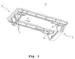
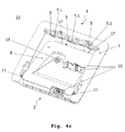
- FIG. 1 an example of a holding frame 1 according to the invention is shown.
- the support frame 1 has a generally rectangular shape with four sides forming a frame profile, with two frame sides facing each other in parallel.
- two guide tracks 4 are configured at a front end or at a front side 2 of the holding frame 1, which is opposite to a rear side 3 and a rear end.
- the guideways 4 serve to receive holding elements 10, which are arranged on a sensor device 8, which according to the invention can be arranged in the holding frame 1.
- On the side opposite the guideways 4 side 3 of the support frame devices are further formed for generating a force F on a sensor device 8, in particular when the sensor device 8 in the support frame 1, through which a guide of holding elements 10, which inventively formed on the sensor device 8 can be forced in the guideways 4.
- the devices are guide bevels 7 in this case.
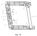
- FIGS. 2a and 2 B show a further example of a holding frame 1 according to the invention from a different perspective.
- the holding frame 1 comprises guideways 4, which are formed on a front side 2 of the holding frame 1.
- the holding frame 1 further comprises means connected to the the guideways 4 opposite side 3 and the rear side 3, the support frame 1 are formed.
- the devices are on the one hand to spring elements 5, which are designed such that they can snap on a sensor device 8 in the holding frame 1 fix or their position, in particular perpendicular to the guide direction of the guideways 4, secure.
- the spring elements 5 are for this purpose partially formed with recesses 5.1, in the matching elements 17, for example, flat springs, which may be formed on the sensor device 8, engage or snap.
- the spring elements 5 are also formed with unlatching elements 6, by which a manual release of the sensor device 8 and the fixation of the sensor device 8 via the spring elements 5 in the holding frame 1 is possible.
- oblique guideways 7 and rigid guide elements 11 are arranged on the guideways 4 opposite side 3 of the support tracks, which generate a force F in the guide direction of the guideways 4 on the sensor device 8 in their arrangement in the support frame 1, and thus a guide of Sensor device 8 and their holding elements 10 in the guideways 4 effect.
- the rigid guide elements 11 serve in particular for the lateral guidance or for the lateral centering of a sensor device 8 when arranged in the holding frame 1.
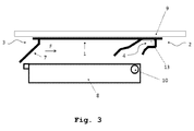
- Fig. 3 is a schematic diagram of the holding frame 1 according to the invention, in particular for illustrating the principle of operation in the arrangement of a sensor device 8 in the holding frame 1.
- the holding frame 1 is arranged on a vehicle window 9, for example on the windshield of a vehicle.
- guideways 4 are configured according to the invention.
- On the guide tracks 4 opposite side 3 of the holding frame 1 devices 7 are configured, which force a force F to guide holding elements 10 of the sensor device 8 in the guide tracks 4, in particular when the sensor device 8 is arranged in the holding frame.
- the guideways 4 are in the example Fig. 3 formed with an S-shaped profile and in a region 13 which corresponds to an end position of the sensor device 8 and the holding elements 10, with an alignment parallel to the vehicle plate 9 alignment.
- the formed on the sensor device 8 holding elements 10 are shown in this case as cylindrical bolts. Due to the parallel design of the guideways 4 in the end position 13 and a cylindrical configuration of the holding elements 10 of the sensor device 8, a particularly simple and relatively powerless fixation of the sensor device 8 in the holding frame 1 is achieved.
- a long-term stable positioning of the sensor device 8 can be achieved via additional devices 5, with a Verschnapp- or latching mechanism on the guide tracks 4 opposite side 3 of the support frame 1, which can advantageously be substantially powerless, since preferably only a backup against Falling out of the sensor device 8 from the support frame 1 is required.
- no disadvantageous phenomena occur in the securing or fixing of a sensor device, such as, for example, flowing, and thus no release of the sensor device over time.
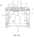
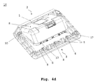
- the Fig. 4a to d show an example of a sensor arrangement 14 according to the invention from a different perspective.
- the sensor arrangement 14 can be arranged, for example, in the interior of a vehicle behind a vehicle window 9 and comprises a holding frame 1 and a sensor device 8.
- the sensor device 8 in this case is a combination of a vehicle camera 15 and a LIDAR sensor 16 (Light D etection A nd R anging).
- the sensor device 8 comprises holding elements 10 which are arranged in guide tracks 4 of the holding frame 1.
- the support frame 1 corresponds in this case the support frame 1 of the invention FIGS.
- the guideways 4 of the holding frame 1 are designed such that the sensor device 8 is brought in arrangement in the holding frame 1 via the holding elements 10 in the guideways 4 in a defined path to the vehicle window 9.
- the sensor assembly 14 is formed in the illustrated embodiment on the guide tracks 4 opposite side 3 with a latching mechanism, in this case with stops 17 on the sensor device 8 and recesses 5.1 on the spring elements 5 of the support frame 1, which upon reaching an end position of the holding elements 10 in the guideways 4 and in particular in pressing the rear part of the sensor device 8 in the holding frame 1 intermesh or snuggle with each other.
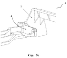
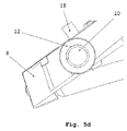
- FIGS. 5a to 5d show detailed representations of various elements of the holding frame 1 according to the invention and the sensor arrangement 14 according to the invention
- FIGS. 5a and 5b are each detailed representations of the front portion 2 of the support frame 1 according to the invention and show a preferred embodiment of the guideways.
- Fig. 5c shows a holding element 10 of a sensor device 8 in a guideway 4 of a holding frame 1 according to the invention.
- Fig. 5d shows a detailed view of a front portion of a sensor device 8 and a formed on the sensor device 8 holding member 10.
- the holding member 10 is configured in this case with a cockroach 12.
- the scraping nose 12 serves to compensate for tolerances and is arranged on the upper side of the holding element 10, ie on the arrangement of the sensor device in the holding frame 1 of the vehicle window 9 facing side, so that the holding element 10 in the arrangement of the sensor device 8 in the holding frame 1 by the cockroach 12th down (or away from the disc 9) is pressed and whereby the distance of the sensor device 8 to the vehicle window 9 is kept constant.
- On sensor device 8 off Fig. 5d is on the vehicle window 9 side facing an elastic member 18 is arranged.
- the elastic element 18, which may be, for example, sponge rubber, is located in the holding frame 1 directly between disc 9 and sensor device 8 and can thereby protect against noise, for example due to vibration, and / or for separating the light beams emitted from the LIDAR sensor 16 from the received light beams.
Landscapes
- Engineering & Computer Science (AREA)
- Mechanical Engineering (AREA)
- Physics & Mathematics (AREA)
- Computer Networks & Wireless Communication (AREA)
- General Physics & Mathematics (AREA)
- Radar, Positioning & Navigation (AREA)
- Remote Sensing (AREA)
- Electromagnetism (AREA)
- Fittings On The Vehicle Exterior For Carrying Loads, And Devices For Holding Or Mounting Articles (AREA)
- Window Of Vehicle (AREA)
- Optical Radar Systems And Details Thereof (AREA)
Applications Claiming Priority (2)
| Application Number | Priority Date | Filing Date | Title |
|---|---|---|---|
| DE102012101781.6A DE102012101781B4 (de) | 2012-03-02 | 2012-03-02 | Halterahmen für Sensorvorrichtungen in Fahrzeugen |
| PCT/DE2013/100045 WO2013127388A1 (de) | 2012-03-02 | 2013-02-08 | Halterahmen für sensorvorrichtungen in fahrzeugen |
Publications (2)
| Publication Number | Publication Date |
|---|---|
| EP2819885A1 EP2819885A1 (de) | 2015-01-07 |
| EP2819885B1 true EP2819885B1 (de) | 2016-05-04 |
Family
ID=47779800
Family Applications (1)
| Application Number | Title | Priority Date | Filing Date |
|---|---|---|---|
| EP13707099.1A Not-in-force EP2819885B1 (de) | 2012-03-02 | 2013-02-08 | Halterahmen für sensorvorrichtungen in fahrzeugen |
Country Status (7)
| Country | Link |
|---|---|
| US (1) | US9487156B2 (enExample) |
| EP (1) | EP2819885B1 (enExample) |
| JP (1) | JP6278905B2 (enExample) |
| KR (1) | KR101954327B1 (enExample) |
| CN (1) | CN104080654B (enExample) |
| DE (1) | DE102012101781B4 (enExample) |
| WO (1) | WO2013127388A1 (enExample) |
Cited By (4)
| Publication number | Priority date | Publication date | Assignee | Title |
|---|---|---|---|---|
| DE102020107071B4 (de) * | 2019-05-09 | 2021-03-04 | Bayerische Motoren Werke Aktiengesellschaft | Trägerelement für ein Mobilgerät und Halterungsanordnung |
| DE102020107070B4 (de) * | 2019-05-09 | 2021-03-04 | Bayerische Motoren Werke Aktiengesellschaft | Halterungsanordnung zur Befestigung eines Mobilgeräts |
| US11938869B2 (en) | 2018-10-02 | 2024-03-26 | Pilkington Group Limited | Windscreen |
| US11987185B2 (en) | 2019-08-23 | 2024-05-21 | Pilkington Group Limited | Windscreen |
Families Citing this family (36)
| Publication number | Priority date | Publication date | Assignee | Title |
|---|---|---|---|---|
| DE102012101781B4 (de) * | 2012-03-02 | 2014-07-10 | Continental Automotive Gmbh | Halterahmen für Sensorvorrichtungen in Fahrzeugen |
| DE102013009909A1 (de) * | 2013-06-13 | 2014-04-17 | Daimler Ag | Trägervorrichtung zur Befestigung an einer Scheibe eines Kraftwagens, Sensoreinrichtung und Anordnung einer Sensoreinrichtung an einer Trägervorrichtung |
| EP2835876A1 (de) * | 2013-08-05 | 2015-02-11 | Continental Automotive GmbH | Modulgehäuse für elektronische Baugruppe |
| US9487161B2 (en) | 2013-10-04 | 2016-11-08 | Magna Mirrors Of America, Inc. | Accessory system for a vehicle |
| DE102014012001B4 (de) * | 2014-08-12 | 2021-07-22 | Daimler Ag | Trägervorrichtung zum Befestigen an einer Scheibe eines Kraftwagens und Kraftwagen |
| US10678261B2 (en) | 2015-02-06 | 2020-06-09 | Aptiv Technologies Limited | Method and apparatus for controlling an autonomous vehicle |
| US20180012492A1 (en) | 2015-02-06 | 2018-01-11 | Delphi Technologies, Inc. | Method of automatically controlling an autonomous vehicle based on electronic messages from roadside infrastructure or other vehicles |
| US20170371036A1 (en) * | 2015-02-06 | 2017-12-28 | Delphi Technologies, Inc. | Autonomous vehicle with unobtrusive sensors |
| JP6350826B2 (ja) * | 2015-03-31 | 2018-07-04 | トヨタ自動車株式会社 | 車両前方情報取得装置 |
| US9933109B2 (en) | 2015-06-03 | 2018-04-03 | Dgm Enterprises Llc | Vibration resistant equipment mount |
| US10232798B2 (en) * | 2016-01-29 | 2019-03-19 | Veoneer Us, Inc. | Apparatuses for mounting camera arrangements on motor vehicles |
| JP6510999B2 (ja) | 2016-03-24 | 2019-05-08 | 本田技研工業株式会社 | センサブラケット |
| JP6316329B2 (ja) * | 2016-03-24 | 2018-04-25 | 本田技研工業株式会社 | センサブラケット |
| JP6494569B2 (ja) * | 2016-07-20 | 2019-04-03 | 株式会社ニフコ | カメラユニット |
| EP3279043B1 (en) * | 2016-08-05 | 2018-12-05 | MEAS France | Sensor mounting system |
| EP3518031B1 (en) * | 2016-09-21 | 2021-05-26 | Hitachi Automotive Systems, Ltd. | Imaging device |
| EP3518033B1 (en) * | 2016-09-21 | 2021-04-14 | Hitachi Automotive Systems, Ltd. | Imaging device |
| US10800343B2 (en) * | 2016-11-18 | 2020-10-13 | Honda Motor Co., Ltd. | Onboard electronic device mounting structure |
| US10338198B2 (en) * | 2017-04-03 | 2019-07-02 | Ford Global Technologies, Llc | Sensor apparatus |
| US10488494B2 (en) | 2017-04-03 | 2019-11-26 | Ford Global Technologies, Llc | Sensor apparatus |
| DE102017209492A1 (de) * | 2017-06-06 | 2018-12-06 | Continental Automotive Gmbh | Halterung zur Befestigung eines Sensors, insbesondere Radarsensors, an einem Fahrzeug und ein System aus einer Halterung und dem Sensor |
| DE102017210291A1 (de) * | 2017-06-20 | 2018-12-20 | Continental Automotive Gmbh | Halterung zur Befestigung eines Sensors, insbesondere Radarsensors, an einem Fahrzeug und ein System aus einer Halterung und dem Sensor |
| DE112018000169A5 (de) | 2017-06-20 | 2019-08-08 | Continental Automotive Gmbh | Halterung zur Befestigung eines Sensors, insbesondere Radarsensors, an einem Fahrzeug und ein System aus einer Halterung und dem Sensor |
| US10953817B2 (en) * | 2017-08-15 | 2021-03-23 | Methode Electronics, Inc. | Locking bracket for vehicle accessory |
| DE102017120242A1 (de) * | 2017-09-04 | 2019-03-07 | Peiker Acustic Gmbh & Co. Kg | Telematikeinheit, Baugruppe eines Fahrzeugs und Verfahren zur Montage und Demontage einer Telematikeinheit |
| DE102017120241A1 (de) * | 2017-09-04 | 2019-03-07 | Peiker Acustic Gmbh & Co. Kg | Verfahren zur Montage und Demontage einer Telematikeinheit, Telematikeinheit und Baugruppe eines Fahrzeugs |
| DE102017215735B4 (de) * | 2017-09-07 | 2024-08-08 | Bayerische Motoren Werke Aktiengesellschaft | Haltevorrichtung zum Halten einer Fahrzeugkomponente an einer Scheibenfläche eines Kraftfahrzeugs |
| DE102017221890A1 (de) * | 2017-12-05 | 2019-06-06 | Continental Automotive Gmbh | Sensoranordnung und Kraftfahrzeug |
| DE102017222219A1 (de) * | 2017-12-08 | 2019-06-13 | Continental Automotive Gmbh | Sensoranordnung und kraftfahrzeug |
| US10556553B2 (en) | 2018-05-15 | 2020-02-11 | Veoneer Us, Inc. | Vehicle camera mounting interfaces |
| US11592526B2 (en) * | 2018-05-15 | 2023-02-28 | Uatc, Llc | Lidar sensor assembly including dovetail joint coupling features |
| DE102018125065B3 (de) * | 2018-10-10 | 2019-11-21 | Bayerische Motoren Werke Aktiengesellschaft | Haltevorrichtung zur Halterung wenigstens einer Fahrerassistenzsensoreinheit sowie Anordnung einer Haltevorrichtung |
| US12000171B2 (en) * | 2019-03-15 | 2024-06-04 | Deere & Company | Mounting system for mounting an electronic device on a vehicle |
| US11433827B2 (en) * | 2019-06-07 | 2022-09-06 | Volvo Car Corporation | Bracket assembly for securing a safety equipment module to a windowpane of a vehicle |
| JP7390243B2 (ja) * | 2020-04-17 | 2023-12-01 | 株式会社ニフコ | 車載機器用ブラケット |
| DE102022209527A1 (de) | 2022-09-13 | 2024-03-14 | Robert Bosch Gesellschaft mit beschränkter Haftung | Lidar-System |
Family Cites Families (38)
| Publication number | Priority date | Publication date | Assignee | Title |
|---|---|---|---|---|
| US2427335A (en) * | 1945-03-09 | 1947-09-16 | Vega C Antonia | Support for kitchen containers |
| US3035806A (en) * | 1959-07-27 | 1962-05-22 | Collins Radio Co | Radio hold-down device |
| US3165163A (en) * | 1962-05-24 | 1965-01-12 | Ford Motor Co | Battery mounting device |
| DE1780551B2 (de) * | 1968-09-27 | 1974-06-06 | Volkswagenwerk Ag, 3180 Wolfsburg | Haltevorrichtung für Akkumulatorgehäuse |
| JPH01315193A (ja) * | 1988-06-14 | 1989-12-20 | Mitsubishi Electric Corp | 機器取付装置 |
| US5398157A (en) * | 1993-04-13 | 1995-03-14 | Kingston Technology Corporation | Snap-in mounting bracket for a computer memory device |
| US5484667A (en) * | 1993-09-07 | 1996-01-16 | Gnb Battery Technologies Inc. | Spacers for lead-acid batteries |
| DE4408686C1 (de) * | 1994-03-15 | 1995-04-27 | Keiper Recaro Gmbh Co | Vorrichtung zum Verbinden eines Längsträgers eines Fahrzeugsitzes mit der Fahrzeugstruktur |
| DE9419679U1 (de) * | 1994-12-08 | 1995-03-02 | Hama GmbH & Co, 86653 Monheim | Halterungsvorrichtung für ein Funktelefon in einem Fahrzeug |
| SE9503952L (sv) * | 1995-11-08 | 1996-09-23 | Peter Soederstroem | Monteringsbygel |
| US5730414A (en) * | 1996-04-26 | 1998-03-24 | The Crown Division | Removable storage assembly fastening system |
| US5950973A (en) * | 1997-04-21 | 1999-09-14 | Delco Electronics | Housing mounting system |
| US6230834B1 (en) * | 1999-09-16 | 2001-05-15 | Daimlerchrysler Corporation | Battery mounting system |
| US6666362B1 (en) * | 2000-02-17 | 2003-12-23 | Sai Automotive Usa-Sal, Inc. | Cargo management container/organizer attachment apparatus and method |
| US7344116B2 (en) * | 2004-06-02 | 2008-03-18 | North South Machine Shop, Inc. | Release bracket system and method |
| US7523528B2 (en) * | 2005-07-28 | 2009-04-28 | Carnevali Jeffrey D | Thumb release mounting apparatus |
| FR2891515B1 (fr) * | 2005-10-05 | 2008-02-29 | Raymond Et Cie Soc En Commandi | Dispositif de fixation d'une batterie |
| DE102006040213C5 (de) * | 2006-01-19 | 2019-08-01 | Bcs Automotive Interface Solutions Gmbh | Halteklammer für einen Regensensor |
| US7806308B2 (en) * | 2006-09-14 | 2010-10-05 | Midwest Bus Corporation | Releasable mounting of bicycle rack on vehicle bumper |
| JP4667430B2 (ja) * | 2007-08-09 | 2011-04-13 | 日立オートモティブシステムズ株式会社 | 車載用カメラ |
| DE202008003168U1 (de) * | 2008-03-06 | 2008-06-26 | Trw Automotive Electronics & Components Gmbh | Sensor mit Halterung |
| JP5231860B2 (ja) * | 2008-05-09 | 2013-07-10 | 富士通テン株式会社 | 電子機器 |
| JP2009269570A (ja) * | 2008-05-09 | 2009-11-19 | Fujitsu Ten Ltd | 電子機器 |
| US8348112B2 (en) * | 2008-07-30 | 2013-01-08 | Deere & Company | Mounting system for mounting an electronic device on a vehicle |
| DE102008047470A1 (de) * | 2008-09-17 | 2010-04-15 | J. Eberspächer GmbH & Co. KG | Befestigungseinrichtung, insbesondere bei Kraftfahrzeugen |
| US9032593B2 (en) * | 2009-10-05 | 2015-05-19 | RayoMar Enterprise, Inc. | Fastening or mounting apparatus |
| DE102010010571A1 (de) * | 2010-03-05 | 2011-09-08 | Conti Temic Microelectronic Gmbh | Befestigungsvorrichtung für Sensorgehäuse in einem Kraftfahrzeuginnenraum |
| FR2965527B1 (fr) * | 2010-09-30 | 2016-05-13 | Faurecia Interieur Ind | Support de fixation d'un appareil electronique portatif, planche de bord et vehicule automobile correspondants. |
| JP5704886B2 (ja) * | 2010-10-25 | 2015-04-22 | 日本電産エレシス株式会社 | 車載カメラの取付構造 |
| US8413947B2 (en) * | 2010-11-12 | 2013-04-09 | Joy Industrial Co., Ltd. | Positioning device for battery box |
| JP5316562B2 (ja) * | 2011-02-10 | 2013-10-16 | 株式会社デンソー | 車載カメラ |
| JP5672539B2 (ja) * | 2011-01-11 | 2015-02-18 | トヨタ自動車株式会社 | 車両用カメラユニットおよびブラケット |
| DE102011107353B4 (de) * | 2011-07-14 | 2022-03-24 | HELLA GmbH & Co. KGaA | Haltevorrichtung für einen Scheibensensor |
| DE102012101781B4 (de) * | 2012-03-02 | 2014-07-10 | Continental Automotive Gmbh | Halterahmen für Sensorvorrichtungen in Fahrzeugen |
| JP6028382B2 (ja) * | 2012-04-27 | 2016-11-16 | 株式会社デンソー | 前方監視カメラ |
| WO2014141357A1 (ja) * | 2013-03-11 | 2014-09-18 | 本田技研工業株式会社 | カメラユニット、車両及びカメラユニットの製造方法 |
| JP5947759B2 (ja) * | 2013-07-23 | 2016-07-06 | 本田技研工業株式会社 | カメラユニット |
| JP6052246B2 (ja) * | 2014-07-10 | 2016-12-27 | トヨタ自動車株式会社 | 車載カメラの取り付け構造 |
-
2012
- 2012-03-02 DE DE102012101781.6A patent/DE102012101781B4/de not_active Expired - Fee Related
-
2013
- 2013-02-08 EP EP13707099.1A patent/EP2819885B1/de not_active Not-in-force
- 2013-02-08 US US14/381,677 patent/US9487156B2/en not_active Expired - Fee Related
- 2013-02-08 WO PCT/DE2013/100045 patent/WO2013127388A1/de not_active Ceased
- 2013-02-08 CN CN201380007404.7A patent/CN104080654B/zh not_active Expired - Fee Related
- 2013-02-08 JP JP2014559098A patent/JP6278905B2/ja not_active Expired - Fee Related
- 2013-02-08 KR KR1020147019856A patent/KR101954327B1/ko not_active Expired - Fee Related
Non-Patent Citations (1)
| Title |
|---|
| None * |
Cited By (4)
| Publication number | Priority date | Publication date | Assignee | Title |
|---|---|---|---|---|
| US11938869B2 (en) | 2018-10-02 | 2024-03-26 | Pilkington Group Limited | Windscreen |
| DE102020107071B4 (de) * | 2019-05-09 | 2021-03-04 | Bayerische Motoren Werke Aktiengesellschaft | Trägerelement für ein Mobilgerät und Halterungsanordnung |
| DE102020107070B4 (de) * | 2019-05-09 | 2021-03-04 | Bayerische Motoren Werke Aktiengesellschaft | Halterungsanordnung zur Befestigung eines Mobilgeräts |
| US11987185B2 (en) | 2019-08-23 | 2024-05-21 | Pilkington Group Limited | Windscreen |
Also Published As
| Publication number | Publication date |
|---|---|
| KR20140143133A (ko) | 2014-12-15 |
| EP2819885A1 (de) | 2015-01-07 |
| DE102012101781A1 (de) | 2013-09-05 |
| JP6278905B2 (ja) | 2018-02-14 |
| US9487156B2 (en) | 2016-11-08 |
| US20150041510A1 (en) | 2015-02-12 |
| DE102012101781B4 (de) | 2014-07-10 |
| KR101954327B1 (ko) | 2019-03-05 |
| CN104080654A (zh) | 2014-10-01 |
| JP2015508728A (ja) | 2015-03-23 |
| WO2013127388A1 (de) | 2013-09-06 |
| CN104080654B (zh) | 2016-11-16 |
Similar Documents
| Publication | Publication Date | Title |
|---|---|---|
| EP2819885B1 (de) | Halterahmen für sensorvorrichtungen in fahrzeugen | |
| EP2914463B1 (de) | Halterung zum befestigen eines bauteils an einer glasscheibe | |
| DE102013005801B4 (de) | Trägervorrichtung zur Befestigung an einer Scheibe eines Kraftwagens und Kraftwagen | |
| DE112017005837B4 (de) | Montagestruktur für ein elektronisches fahrzeugbordgerät | |
| EP3335059B1 (de) | Ultraschallsensorvorrichtung für ein kraftfahrzeug mit zweiteiliger befestigungsvorrichtung, verkleidungsanordnung, kraftfahrzeug sowie verfahren | |
| EP3642082B1 (de) | Halterung zur befestigung eines sensors, insbesondere radarsensors, an einem fahrzeug und ein system aus einer halterung und dem sensor | |
| DE10114018B4 (de) | Aufnahme- und Verbindungsvorrichtung für eine Bug/Heckschürze eines Kraftfahrzeugs | |
| DE102016221434B4 (de) | Monitor eines Kamera-Monitor-Systems | |
| EP2736769A1 (de) | Befestigungsanordnung eines sensorelements an einem befestigungselement eines kraftwagens | |
| DE102019108882A1 (de) | Halterungsbasisteil zur Befestigung wenigstens eines Kameragehäuses an einem Fahrzeugteil eines Fahrzeugs, Kameragehäuse und Kamerasystem | |
| EP2539180B1 (de) | Halteeinrichtung zur halterung eines innenspiegelmoduls an einer windschutzscheibe | |
| DE19647203C2 (de) | Gehäuse für Dachmodul | |
| WO2005086473A1 (de) | Kamera | |
| DE102012024274A1 (de) | Halterungsvorrichtung zur Aufnahme und Befestigung eines Spiegels an einer Fahrzeugscheibe, Spiegeleinrichtung und Fahrzeug | |
| DE102011108322B4 (de) | Anbindung eines Anbauelements an einem Nutzfahrzeugrahmen | |
| DE102017222219A1 (de) | Sensoranordnung und kraftfahrzeug | |
| DE102017221890A1 (de) | Sensoranordnung und Kraftfahrzeug | |
| DE102007019935A1 (de) | Befestigungsanordnung mit einem Stoßfänger und einem Kotflügel für ein Kraftfahrzeug | |
| EP2892762A1 (de) | Kraftfahrzeug mit einem airbagmodul | |
| DE102008050265B4 (de) | Aggregateträger mit Verstärkungselement | |
| DE102011109829A1 (de) | Befestigungsanordnung eines Gehäuses einer Fahrzeugkomponente an einem Fahrzeugbauteil und Gehäuse für eine Fahrzeugkomponente | |
| DE102005049140A1 (de) | Vorrichtung zur Befestigung eines Sensors | |
| EP2026436A2 (de) | Isolierprofil | |
| DE102024133972B3 (de) | Kraftfahrzeug mit beweglichem Sensor und Sensorhalterung | |
| DE102007004018A1 (de) | Befestigung für eine in einem Ausschnitt einer Einbauwand einsetzbare kastenförmige Aufnahmehalterung |
Legal Events
| Date | Code | Title | Description |
|---|---|---|---|
| PUAI | Public reference made under article 153(3) epc to a published international application that has entered the european phase |
Free format text: ORIGINAL CODE: 0009012 |
|
| 17P | Request for examination filed |
Effective date: 20141002 |
|
| AK | Designated contracting states |
Kind code of ref document: A1 Designated state(s): AL AT BE BG CH CY CZ DE DK EE ES FI FR GB GR HR HU IE IS IT LI LT LU LV MC MK MT NL NO PL PT RO RS SE SI SK SM TR |
|
| AX | Request for extension of the european patent |
Extension state: BA ME |
|
| RIN1 | Information on inventor provided before grant (corrected) |
Inventor name: AUGUSTIN, THOMAS Inventor name: FRENZEL, HENRYK Inventor name: SAUERER, VINZENZ |
|
| DAX | Request for extension of the european patent (deleted) | ||
| GRAP | Despatch of communication of intention to grant a patent |
Free format text: ORIGINAL CODE: EPIDOSNIGR1 |
|
| INTG | Intention to grant announced |
Effective date: 20151126 |
|
| INTG | Intention to grant announced |
Effective date: 20160209 |
|
| GRAS | Grant fee paid |
Free format text: ORIGINAL CODE: EPIDOSNIGR3 |
|
| GRAA | (expected) grant |
Free format text: ORIGINAL CODE: 0009210 |
|
| RBV | Designated contracting states (corrected) |
Designated state(s): AL AT BE BG CH CY CZ DK EE ES FI FR GB GR HR HU IE IS IT LI LT LU LV MC MK MT NL NO PL PT RO RS SE SI SK SM TR |
|
| REG | Reference to a national code |
Ref country code: DE Ref legal event code: R108 |
|
| AK | Designated contracting states |
Kind code of ref document: B1 Designated state(s): AL AT BE BG CH CY CZ DK EE ES FI FR GB GR HR HU IE IS IT LI LT LU LV MC MK MT NL NO PL PT RO RS SE SI SK SM TR |
|
| REG | Reference to a national code |
Ref country code: GB Ref legal event code: FG4D Free format text: NOT ENGLISH |
|
| REG | Reference to a national code |
Ref country code: CH Ref legal event code: EP |
|
| REG | Reference to a national code |
Ref country code: AT Ref legal event code: REF Ref document number: 796602 Country of ref document: AT Kind code of ref document: T Effective date: 20160515 |
|
| REG | Reference to a national code |
Ref country code: IE Ref legal event code: FG4D Free format text: LANGUAGE OF EP DOCUMENT: GERMAN |
|
| REG | Reference to a national code |
Ref country code: NL Ref legal event code: MP Effective date: 20160504 |
|
| REG | Reference to a national code |
Ref country code: LT Ref legal event code: MG4D |
|
| PG25 | Lapsed in a contracting state [announced via postgrant information from national office to epo] |
Ref country code: FI Free format text: LAPSE BECAUSE OF FAILURE TO SUBMIT A TRANSLATION OF THE DESCRIPTION OR TO PAY THE FEE WITHIN THE PRESCRIBED TIME-LIMIT Effective date: 20160504 Ref country code: LT Free format text: LAPSE BECAUSE OF FAILURE TO SUBMIT A TRANSLATION OF THE DESCRIPTION OR TO PAY THE FEE WITHIN THE PRESCRIBED TIME-LIMIT Effective date: 20160504 Ref country code: NL Free format text: LAPSE BECAUSE OF FAILURE TO SUBMIT A TRANSLATION OF THE DESCRIPTION OR TO PAY THE FEE WITHIN THE PRESCRIBED TIME-LIMIT Effective date: 20160504 Ref country code: NO Free format text: LAPSE BECAUSE OF FAILURE TO SUBMIT A TRANSLATION OF THE DESCRIPTION OR TO PAY THE FEE WITHIN THE PRESCRIBED TIME-LIMIT Effective date: 20160804 |
|
| PG25 | Lapsed in a contracting state [announced via postgrant information from national office to epo] |
Ref country code: GR Free format text: LAPSE BECAUSE OF FAILURE TO SUBMIT A TRANSLATION OF THE DESCRIPTION OR TO PAY THE FEE WITHIN THE PRESCRIBED TIME-LIMIT Effective date: 20160805 Ref country code: PT Free format text: LAPSE BECAUSE OF FAILURE TO SUBMIT A TRANSLATION OF THE DESCRIPTION OR TO PAY THE FEE WITHIN THE PRESCRIBED TIME-LIMIT Effective date: 20160905 Ref country code: ES Free format text: LAPSE BECAUSE OF FAILURE TO SUBMIT A TRANSLATION OF THE DESCRIPTION OR TO PAY THE FEE WITHIN THE PRESCRIBED TIME-LIMIT Effective date: 20160504 Ref country code: LV Free format text: LAPSE BECAUSE OF FAILURE TO SUBMIT A TRANSLATION OF THE DESCRIPTION OR TO PAY THE FEE WITHIN THE PRESCRIBED TIME-LIMIT Effective date: 20160504 Ref country code: RS Free format text: LAPSE BECAUSE OF FAILURE TO SUBMIT A TRANSLATION OF THE DESCRIPTION OR TO PAY THE FEE WITHIN THE PRESCRIBED TIME-LIMIT Effective date: 20160504 Ref country code: HR Free format text: LAPSE BECAUSE OF FAILURE TO SUBMIT A TRANSLATION OF THE DESCRIPTION OR TO PAY THE FEE WITHIN THE PRESCRIBED TIME-LIMIT Effective date: 20160504 Ref country code: SE Free format text: LAPSE BECAUSE OF FAILURE TO SUBMIT A TRANSLATION OF THE DESCRIPTION OR TO PAY THE FEE WITHIN THE PRESCRIBED TIME-LIMIT Effective date: 20160504 |
|
| PG25 | Lapsed in a contracting state [announced via postgrant information from national office to epo] |
Ref country code: IT Free format text: LAPSE BECAUSE OF FAILURE TO SUBMIT A TRANSLATION OF THE DESCRIPTION OR TO PAY THE FEE WITHIN THE PRESCRIBED TIME-LIMIT Effective date: 20160504 |
|
| PG25 | Lapsed in a contracting state [announced via postgrant information from national office to epo] |
Ref country code: DK Free format text: LAPSE BECAUSE OF FAILURE TO SUBMIT A TRANSLATION OF THE DESCRIPTION OR TO PAY THE FEE WITHIN THE PRESCRIBED TIME-LIMIT Effective date: 20160504 Ref country code: RO Free format text: LAPSE BECAUSE OF FAILURE TO SUBMIT A TRANSLATION OF THE DESCRIPTION OR TO PAY THE FEE WITHIN THE PRESCRIBED TIME-LIMIT Effective date: 20160504 Ref country code: EE Free format text: LAPSE BECAUSE OF FAILURE TO SUBMIT A TRANSLATION OF THE DESCRIPTION OR TO PAY THE FEE WITHIN THE PRESCRIBED TIME-LIMIT Effective date: 20160504 Ref country code: SK Free format text: LAPSE BECAUSE OF FAILURE TO SUBMIT A TRANSLATION OF THE DESCRIPTION OR TO PAY THE FEE WITHIN THE PRESCRIBED TIME-LIMIT Effective date: 20160504 Ref country code: CZ Free format text: LAPSE BECAUSE OF FAILURE TO SUBMIT A TRANSLATION OF THE DESCRIPTION OR TO PAY THE FEE WITHIN THE PRESCRIBED TIME-LIMIT Effective date: 20160504 |
|
| REG | Reference to a national code |
Ref country code: FR Ref legal event code: PLFP Year of fee payment: 5 |
|
| PG25 | Lapsed in a contracting state [announced via postgrant information from national office to epo] |
Ref country code: PL Free format text: LAPSE BECAUSE OF FAILURE TO SUBMIT A TRANSLATION OF THE DESCRIPTION OR TO PAY THE FEE WITHIN THE PRESCRIBED TIME-LIMIT Effective date: 20160504 Ref country code: SM Free format text: LAPSE BECAUSE OF FAILURE TO SUBMIT A TRANSLATION OF THE DESCRIPTION OR TO PAY THE FEE WITHIN THE PRESCRIBED TIME-LIMIT Effective date: 20160504 |
|
| PLBE | No opposition filed within time limit |
Free format text: ORIGINAL CODE: 0009261 |
|
| STAA | Information on the status of an ep patent application or granted ep patent |
Free format text: STATUS: NO OPPOSITION FILED WITHIN TIME LIMIT |
|
| 26N | No opposition filed |
Effective date: 20170207 |
|
| PG25 | Lapsed in a contracting state [announced via postgrant information from national office to epo] |
Ref country code: SI Free format text: LAPSE BECAUSE OF FAILURE TO SUBMIT A TRANSLATION OF THE DESCRIPTION OR TO PAY THE FEE WITHIN THE PRESCRIBED TIME-LIMIT Effective date: 20160504 Ref country code: BE Free format text: LAPSE BECAUSE OF NON-PAYMENT OF DUE FEES Effective date: 20170228 |
|
| PG25 | Lapsed in a contracting state [announced via postgrant information from national office to epo] |
Ref country code: MC Free format text: LAPSE BECAUSE OF FAILURE TO SUBMIT A TRANSLATION OF THE DESCRIPTION OR TO PAY THE FEE WITHIN THE PRESCRIBED TIME-LIMIT Effective date: 20160504 |
|
| REG | Reference to a national code |
Ref country code: CH Ref legal event code: PL |
|
| GBPC | Gb: european patent ceased through non-payment of renewal fee |
Effective date: 20170208 |
|
| PG25 | Lapsed in a contracting state [announced via postgrant information from national office to epo] |
Ref country code: LI Free format text: LAPSE BECAUSE OF NON-PAYMENT OF DUE FEES Effective date: 20170228 Ref country code: CH Free format text: LAPSE BECAUSE OF NON-PAYMENT OF DUE FEES Effective date: 20170228 |
|
| REG | Reference to a national code |
Ref country code: IE Ref legal event code: MM4A |
|
| PG25 | Lapsed in a contracting state [announced via postgrant information from national office to epo] |
Ref country code: LU Free format text: LAPSE BECAUSE OF NON-PAYMENT OF DUE FEES Effective date: 20170208 |
|
| REG | Reference to a national code |
Ref country code: BE Ref legal event code: MM Effective date: 20170228 |
|
| REG | Reference to a national code |
Ref country code: FR Ref legal event code: PLFP Year of fee payment: 6 |
|
| PG25 | Lapsed in a contracting state [announced via postgrant information from national office to epo] |
Ref country code: IE Free format text: LAPSE BECAUSE OF NON-PAYMENT OF DUE FEES Effective date: 20170208 Ref country code: GB Free format text: LAPSE BECAUSE OF NON-PAYMENT OF DUE FEES Effective date: 20170208 |
|
| PG25 | Lapsed in a contracting state [announced via postgrant information from national office to epo] |
Ref country code: MT Free format text: LAPSE BECAUSE OF FAILURE TO SUBMIT A TRANSLATION OF THE DESCRIPTION OR TO PAY THE FEE WITHIN THE PRESCRIBED TIME-LIMIT Effective date: 20160504 |
|
| PG25 | Lapsed in a contracting state [announced via postgrant information from national office to epo] |
Ref country code: AL Free format text: LAPSE BECAUSE OF FAILURE TO SUBMIT A TRANSLATION OF THE DESCRIPTION OR TO PAY THE FEE WITHIN THE PRESCRIBED TIME-LIMIT Effective date: 20160504 |
|
| REG | Reference to a national code |
Ref country code: AT Ref legal event code: MM01 Ref document number: 796602 Country of ref document: AT Kind code of ref document: T Effective date: 20180208 |
|
| PG25 | Lapsed in a contracting state [announced via postgrant information from national office to epo] |
Ref country code: AT Free format text: LAPSE BECAUSE OF NON-PAYMENT OF DUE FEES Effective date: 20180208 |
|
| PG25 | Lapsed in a contracting state [announced via postgrant information from national office to epo] |
Ref country code: HU Free format text: LAPSE BECAUSE OF FAILURE TO SUBMIT A TRANSLATION OF THE DESCRIPTION OR TO PAY THE FEE WITHIN THE PRESCRIBED TIME-LIMIT; INVALID AB INITIO Effective date: 20130208 |
|
| PG25 | Lapsed in a contracting state [announced via postgrant information from national office to epo] |
Ref country code: BG Free format text: LAPSE BECAUSE OF FAILURE TO SUBMIT A TRANSLATION OF THE DESCRIPTION OR TO PAY THE FEE WITHIN THE PRESCRIBED TIME-LIMIT Effective date: 20160504 |
|
| PG25 | Lapsed in a contracting state [announced via postgrant information from national office to epo] |
Ref country code: CY Free format text: LAPSE BECAUSE OF FAILURE TO SUBMIT A TRANSLATION OF THE DESCRIPTION OR TO PAY THE FEE WITHIN THE PRESCRIBED TIME-LIMIT Effective date: 20160504 |
|
| PG25 | Lapsed in a contracting state [announced via postgrant information from national office to epo] |
Ref country code: MK Free format text: LAPSE BECAUSE OF FAILURE TO SUBMIT A TRANSLATION OF THE DESCRIPTION OR TO PAY THE FEE WITHIN THE PRESCRIBED TIME-LIMIT Effective date: 20160504 |
|
| PG25 | Lapsed in a contracting state [announced via postgrant information from national office to epo] |
Ref country code: TR Free format text: LAPSE BECAUSE OF FAILURE TO SUBMIT A TRANSLATION OF THE DESCRIPTION OR TO PAY THE FEE WITHIN THE PRESCRIBED TIME-LIMIT Effective date: 20160504 |
|
| PG25 | Lapsed in a contracting state [announced via postgrant information from national office to epo] |
Ref country code: IS Free format text: LAPSE BECAUSE OF FAILURE TO SUBMIT A TRANSLATION OF THE DESCRIPTION OR TO PAY THE FEE WITHIN THE PRESCRIBED TIME-LIMIT Effective date: 20160904 |
|
| PGFP | Annual fee paid to national office [announced via postgrant information from national office to epo] |
Ref country code: FR Payment date: 20220216 Year of fee payment: 10 |
|
| PG25 | Lapsed in a contracting state [announced via postgrant information from national office to epo] |
Ref country code: FR Free format text: LAPSE BECAUSE OF NON-PAYMENT OF DUE FEES Effective date: 20230228 |