EP2819843B1 - Pharmaceutical packages comprising glass articles with low-friction coatings - Google Patents
Pharmaceutical packages comprising glass articles with low-friction coatings Download PDFInfo
- Publication number
- EP2819843B1 EP2819843B1 EP13709281.3A EP13709281A EP2819843B1 EP 2819843 B1 EP2819843 B1 EP 2819843B1 EP 13709281 A EP13709281 A EP 13709281A EP 2819843 B1 EP2819843 B1 EP 2819843B1
- Authority
- EP
- European Patent Office
- Prior art keywords
- chemical composition
- glass
- silane
- coupling agent
- friction
- Prior art date
- Legal status (The legal status is an assumption and is not a legal conclusion. Google has not performed a legal analysis and makes no representation as to the accuracy of the status listed.)
- Active
Links
- 239000011521 glass Substances 0.000 title claims description 702
- 238000000576 coating method Methods 0.000 title claims description 311
- 239000000203 mixture Substances 0.000 claims description 431
- 239000000126 substance Substances 0.000 claims description 372
- 239000011248 coating agent Substances 0.000 claims description 269
- 239000007822 coupling agent Substances 0.000 claims description 176
- BLRPTPMANUNPDV-UHFFFAOYSA-N Silane Chemical compound [SiH4] BLRPTPMANUNPDV-UHFFFAOYSA-N 0.000 claims description 168
- 229910000077 silane Inorganic materials 0.000 claims description 168
- 239000000178 monomer Substances 0.000 claims description 136
- 229920000642 polymer Polymers 0.000 claims description 126
- 239000004642 Polyimide Substances 0.000 claims description 69
- 229920001721 polyimide Polymers 0.000 claims description 69
- 125000003118 aryl group Chemical group 0.000 claims description 63
- 150000001412 amines Chemical group 0.000 claims description 42
- -1 polybenzothiazoles Polymers 0.000 claims description 36
- 150000008064 anhydrides Chemical group 0.000 claims description 31
- 230000005540 biological transmission Effects 0.000 claims description 29
- CNODSORTHKVDEM-UHFFFAOYSA-N 4-trimethoxysilylaniline Chemical compound CO[Si](OC)(OC)C1=CC=C(N)C=C1 CNODSORTHKVDEM-UHFFFAOYSA-N 0.000 claims description 22
- 125000001931 aliphatic group Chemical group 0.000 claims description 21
- 239000000413 hydrolysate Substances 0.000 claims description 14
- 238000006116 polymerization reaction Methods 0.000 claims description 13
- 229920002050 silicone resin Polymers 0.000 claims description 12
- 238000006384 oligomerization reaction Methods 0.000 claims description 11
- SJECZPVISLOESU-UHFFFAOYSA-N 3-trimethoxysilylpropan-1-amine Chemical compound CO[Si](OC)(OC)CCCN SJECZPVISLOESU-UHFFFAOYSA-N 0.000 claims description 7
- WECDUOXQLAIPQW-UHFFFAOYSA-N 4,4'-Methylene bis(2-methylaniline) Chemical compound C1=C(N)C(C)=CC(CC=2C=C(C)C(N)=CC=2)=C1 WECDUOXQLAIPQW-UHFFFAOYSA-N 0.000 claims description 7
- VQVIHDPBMFABCQ-UHFFFAOYSA-N 5-(1,3-dioxo-2-benzofuran-5-carbonyl)-2-benzofuran-1,3-dione Chemical compound C1=C2C(=O)OC(=O)C2=CC(C(C=2C=C3C(=O)OC(=O)C3=CC=2)=O)=C1 VQVIHDPBMFABCQ-UHFFFAOYSA-N 0.000 claims description 7
- NUIURNJTPRWVAP-UHFFFAOYSA-N 3,3'-Dimethylbenzidine Chemical compound C1=C(N)C(C)=CC(C=2C=C(C)C(N)=CC=2)=C1 NUIURNJTPRWVAP-UHFFFAOYSA-N 0.000 claims description 6
- RWCCWEUUXYIKHB-UHFFFAOYSA-N benzophenone Chemical group C=1C=CC=CC=1C(=O)C1=CC=CC=C1 RWCCWEUUXYIKHB-UHFFFAOYSA-N 0.000 claims description 6
- 229920002313 fluoropolymer Polymers 0.000 claims description 5
- 239000004811 fluoropolymer Substances 0.000 claims description 5
- 239000004952 Polyamide Substances 0.000 claims description 2
- 125000000623 heterocyclic group Chemical group 0.000 claims description 2
- 229920002492 poly(sulfone) Polymers 0.000 claims description 2
- 229920002647 polyamide Polymers 0.000 claims description 2
- 229920002480 polybenzimidazole Polymers 0.000 claims description 2
- 229920002577 polybenzoxazole Polymers 0.000 claims description 2
- 229920001601 polyetherimide Polymers 0.000 claims description 2
- 229920006389 polyphenyl polymer Polymers 0.000 claims description 2
- 239000004696 Poly ether ether ketone Substances 0.000 claims 1
- 229920002530 polyetherether ketone Polymers 0.000 claims 1
- 239000010410 layer Substances 0.000 description 113
- 239000000243 solution Substances 0.000 description 80
- 150000004985 diamines Chemical class 0.000 description 64
- 238000005299 abrasion Methods 0.000 description 54
- 238000000034 method Methods 0.000 description 46
- XLYOFNOQVPJJNP-UHFFFAOYSA-N water Substances O XLYOFNOQVPJJNP-UHFFFAOYSA-N 0.000 description 41
- 238000012360 testing method Methods 0.000 description 38
- 229910001868 water Inorganic materials 0.000 description 37
- 238000005342 ion exchange Methods 0.000 description 36
- YXFVVABEGXRONW-UHFFFAOYSA-N Toluene Chemical compound CC1=CC=CC=C1 YXFVVABEGXRONW-UHFFFAOYSA-N 0.000 description 33
- SECXISVLQFMRJM-UHFFFAOYSA-N N-Methylpyrrolidone Chemical compound CN1CCCC1=O SECXISVLQFMRJM-UHFFFAOYSA-N 0.000 description 32
- 238000010438 heat treatment Methods 0.000 description 32
- 229920005575 poly(amic acid) Polymers 0.000 description 27
- 238000007906 compression Methods 0.000 description 26
- 230000006835 compression Effects 0.000 description 26
- 238000011082 depyrogenation Methods 0.000 description 25
- 229920005989 resin Polymers 0.000 description 25
- 239000011347 resin Substances 0.000 description 25
- 239000000523 sample Substances 0.000 description 24
- OKKJLVBELUTLKV-UHFFFAOYSA-N Methanol Chemical compound OC OKKJLVBELUTLKV-UHFFFAOYSA-N 0.000 description 21
- 238000004108 freeze drying Methods 0.000 description 21
- 150000003839 salts Chemical class 0.000 description 19
- 238000010943 off-gassing Methods 0.000 description 17
- FGIUAXJPYTZDNR-UHFFFAOYSA-N potassium nitrate Chemical class [K+].[O-][N+]([O-])=O FGIUAXJPYTZDNR-UHFFFAOYSA-N 0.000 description 17
- 230000008569 process Effects 0.000 description 17
- 230000001965 increasing effect Effects 0.000 description 16
- 229920003223 poly(pyromellitimide-1,4-diphenyl ether) Polymers 0.000 description 16
- ZMXDDKWLCZADIW-UHFFFAOYSA-N N,N-Dimethylformamide Chemical compound CN(C)C=O ZMXDDKWLCZADIW-UHFFFAOYSA-N 0.000 description 13
- GTDPSWPPOUPBNX-UHFFFAOYSA-N ac1mqpva Chemical compound CC12C(=O)OC(=O)C1(C)C1(C)C2(C)C(=O)OC1=O GTDPSWPPOUPBNX-UHFFFAOYSA-N 0.000 description 13
- 238000011282 treatment Methods 0.000 description 13
- 238000012669 compression test Methods 0.000 description 12
- OKTJSMMVPCPJKN-UHFFFAOYSA-N Carbon Chemical compound [C] OKTJSMMVPCPJKN-UHFFFAOYSA-N 0.000 description 11
- 150000001447 alkali salts Chemical class 0.000 description 11
- 239000008199 coating composition Substances 0.000 description 11
- 239000011247 coating layer Substances 0.000 description 11
- 239000000463 material Substances 0.000 description 11
- 238000005259 measurement Methods 0.000 description 11
- 239000002904 solvent Substances 0.000 description 11
- 238000012546 transfer Methods 0.000 description 11
- 239000007789 gas Substances 0.000 description 10
- FEYOTPHBSLJJJA-UHFFFAOYSA-N [dimethoxy(phenyl)silyl]oxymethanamine Chemical compound NCO[Si](OC)(OC)C1=CC=CC=C1 FEYOTPHBSLJJJA-UHFFFAOYSA-N 0.000 description 9
- 150000002500 ions Chemical class 0.000 description 9
- 125000002496 methyl group Chemical group [H]C([H])([H])* 0.000 description 9
- 239000003960 organic solvent Substances 0.000 description 9
- 239000002243 precursor Substances 0.000 description 9
- 241000894007 species Species 0.000 description 9
- 238000007669 thermal treatment Methods 0.000 description 9
- 239000002253 acid Substances 0.000 description 8
- 229910052799 carbon Inorganic materials 0.000 description 8
- 238000006243 chemical reaction Methods 0.000 description 8
- 239000008367 deionised water Substances 0.000 description 8
- 238000004519 manufacturing process Methods 0.000 description 8
- 238000004806 packaging method and process Methods 0.000 description 8
- 230000035515 penetration Effects 0.000 description 8
- 239000008194 pharmaceutical composition Substances 0.000 description 8
- 238000013001 point bending Methods 0.000 description 8
- FZHAPNGMFPVSLP-UHFFFAOYSA-N silanamine Chemical compound [SiH3]N FZHAPNGMFPVSLP-UHFFFAOYSA-N 0.000 description 8
- 150000004756 silanes Chemical class 0.000 description 8
- 238000005728 strengthening Methods 0.000 description 8
- 239000003039 volatile agent Substances 0.000 description 8
- 230000000052 comparative effect Effects 0.000 description 7
- 238000011068 loading method Methods 0.000 description 7
- 125000001997 phenyl group Chemical group [H]C1=C([H])C([H])=C(*)C([H])=C1[H] 0.000 description 7
- 125000005372 silanol group Chemical group 0.000 description 7
- 239000000758 substrate Substances 0.000 description 7
- FXHOOIRPVKKKFG-UHFFFAOYSA-N N,N-Dimethylacetamide Chemical compound CN(C)C(C)=O FXHOOIRPVKKKFG-UHFFFAOYSA-N 0.000 description 6
- 125000000217 alkyl group Chemical group 0.000 description 6
- 239000002585 base Substances 0.000 description 6
- 230000007423 decrease Effects 0.000 description 6
- 238000010586 diagram Methods 0.000 description 6
- 239000003814 drug Substances 0.000 description 6
- 238000012545 processing Methods 0.000 description 6
- 238000010926 purge Methods 0.000 description 6
- VYPSYNLAJGMNEJ-UHFFFAOYSA-N silicon dioxide Inorganic materials O=[Si]=O VYPSYNLAJGMNEJ-UHFFFAOYSA-N 0.000 description 6
- 238000005496 tempering Methods 0.000 description 6
- 125000004423 acyloxy group Chemical group 0.000 description 5
- 229910052736 halogen Inorganic materials 0.000 description 5
- 150000002367 halogens Chemical class 0.000 description 5
- 230000002829 reductive effect Effects 0.000 description 5
- 230000000717 retained effect Effects 0.000 description 5
- 230000003068 static effect Effects 0.000 description 5
- GOLCXWYRSKYTSP-UHFFFAOYSA-N Arsenious Acid Chemical compound O1[As]2O[As]1O2 GOLCXWYRSKYTSP-UHFFFAOYSA-N 0.000 description 4
- IJGRMHOSHXDMSA-UHFFFAOYSA-N Atomic nitrogen Chemical compound N#N IJGRMHOSHXDMSA-UHFFFAOYSA-N 0.000 description 4
- GWEVSGVZZGPLCZ-UHFFFAOYSA-N Titan oxide Chemical compound O=[Ti]=O GWEVSGVZZGPLCZ-UHFFFAOYSA-N 0.000 description 4
- XLOMVQKBTHCTTD-UHFFFAOYSA-N Zinc monoxide Chemical compound [Zn]=O XLOMVQKBTHCTTD-UHFFFAOYSA-N 0.000 description 4
- MCMNRKCIXSYSNV-UHFFFAOYSA-N Zirconium dioxide Chemical compound O=[Zr]=O MCMNRKCIXSYSNV-UHFFFAOYSA-N 0.000 description 4
- 239000000853 adhesive Substances 0.000 description 4
- 230000001070 adhesive effect Effects 0.000 description 4
- 239000007864 aqueous solution Substances 0.000 description 4
- 229910021641 deionized water Inorganic materials 0.000 description 4
- 238000011049 filling Methods 0.000 description 4
- 238000001878 scanning electron micrograph Methods 0.000 description 4
- 238000006748 scratching Methods 0.000 description 4
- 230000002393 scratching effect Effects 0.000 description 4
- 239000005361 soda-lime glass Substances 0.000 description 4
- 239000007921 spray Substances 0.000 description 4
- XOLBLPGZBRYERU-UHFFFAOYSA-N tin dioxide Chemical compound O=[Sn]=O XOLBLPGZBRYERU-UHFFFAOYSA-N 0.000 description 4
- 238000005406 washing Methods 0.000 description 4
- VLDPXPPHXDGHEW-UHFFFAOYSA-N 1-chloro-2-dichlorophosphoryloxybenzene Chemical compound ClC1=CC=CC=C1OP(Cl)(Cl)=O VLDPXPPHXDGHEW-UHFFFAOYSA-N 0.000 description 3
- 241000047703 Nonion Species 0.000 description 3
- 229920001774 Perfluoroether Polymers 0.000 description 3
- XUIMIQQOPSSXEZ-UHFFFAOYSA-N Silicon Chemical compound [Si] XUIMIQQOPSSXEZ-UHFFFAOYSA-N 0.000 description 3
- HEMHJVSKTPXQMS-UHFFFAOYSA-M Sodium hydroxide Chemical compound [OH-].[Na+] HEMHJVSKTPXQMS-UHFFFAOYSA-M 0.000 description 3
- ZMANZCXQSJIPKH-UHFFFAOYSA-N Triethylamine Chemical compound CCN(CC)CC ZMANZCXQSJIPKH-UHFFFAOYSA-N 0.000 description 3
- 150000001408 amides Chemical group 0.000 description 3
- 239000003708 ampul Substances 0.000 description 3
- 125000004122 cyclic group Chemical group 0.000 description 3
- 229940079593 drug Drugs 0.000 description 3
- 238000000572 ellipsometry Methods 0.000 description 3
- 230000007613 environmental effect Effects 0.000 description 3
- 230000007062 hydrolysis Effects 0.000 description 3
- 238000006460 hydrolysis reaction Methods 0.000 description 3
- 230000003301 hydrolyzing effect Effects 0.000 description 3
- 230000003993 interaction Effects 0.000 description 3
- 238000001000 micrograph Methods 0.000 description 3
- 230000004048 modification Effects 0.000 description 3
- 238000012986 modification Methods 0.000 description 3
- 230000009467 reduction Effects 0.000 description 3
- 238000000926 separation method Methods 0.000 description 3
- 229910052710 silicon Inorganic materials 0.000 description 3
- 239000010703 silicon Substances 0.000 description 3
- 239000000377 silicon dioxide Substances 0.000 description 3
- 239000007787 solid Substances 0.000 description 3
- 238000001228 spectrum Methods 0.000 description 3
- 238000002834 transmittance Methods 0.000 description 3
- 0 *c1cc(-c(cc2)cc(*=C)c2N)ccc1N Chemical compound *c1cc(-c(cc2)cc(*=C)c2N)ccc1N 0.000 description 2
- WZCQRUWWHSTZEM-UHFFFAOYSA-N 1,3-phenylenediamine Chemical compound NC1=CC=CC(N)=C1 WZCQRUWWHSTZEM-UHFFFAOYSA-N 0.000 description 2
- CBCKQZAAMUWICA-UHFFFAOYSA-N 1,4-phenylenediamine Chemical compound NC1=CC=C(N)C=C1 CBCKQZAAMUWICA-UHFFFAOYSA-N 0.000 description 2
- VOZKAJLKRJDJLL-UHFFFAOYSA-N 2,4-diaminotoluene Chemical compound CC1=CC=C(N)C=C1N VOZKAJLKRJDJLL-UHFFFAOYSA-N 0.000 description 2
- AYKYXWQEBUNJCN-UHFFFAOYSA-N 3-methylfuran-2,5-dione Chemical compound CC1=CC(=O)OC1=O AYKYXWQEBUNJCN-UHFFFAOYSA-N 0.000 description 2
- QQGYZOYWNCKGEK-UHFFFAOYSA-N 5-[(1,3-dioxo-2-benzofuran-5-yl)oxy]-2-benzofuran-1,3-dione Chemical compound C1=C2C(=O)OC(=O)C2=CC(OC=2C=C3C(=O)OC(C3=CC=2)=O)=C1 QQGYZOYWNCKGEK-UHFFFAOYSA-N 0.000 description 2
- QHHKLPCQTTWFSS-UHFFFAOYSA-N 5-[2-(1,3-dioxo-2-benzofuran-5-yl)-1,1,1,3,3,3-hexafluoropropan-2-yl]-2-benzofuran-1,3-dione Chemical compound C1=C2C(=O)OC(=O)C2=CC(C(C=2C=C3C(=O)OC(=O)C3=CC=2)(C(F)(F)F)C(F)(F)F)=C1 QHHKLPCQTTWFSS-UHFFFAOYSA-N 0.000 description 2
- RZVAJINKPMORJF-UHFFFAOYSA-N Acetaminophen Chemical compound CC(=O)NC1=CC=C(O)C=C1 RZVAJINKPMORJF-UHFFFAOYSA-N 0.000 description 2
- ZOXJGFHDIHLPTG-UHFFFAOYSA-N Boron Chemical compound [B] ZOXJGFHDIHLPTG-UHFFFAOYSA-N 0.000 description 2
- LFQSCWFLJHTTHZ-UHFFFAOYSA-N Ethanol Chemical compound CCO LFQSCWFLJHTTHZ-UHFFFAOYSA-N 0.000 description 2
- ATUOYWHBWRKTHZ-UHFFFAOYSA-N Propane Chemical compound CCC ATUOYWHBWRKTHZ-UHFFFAOYSA-N 0.000 description 2
- 239000006087 Silane Coupling Agent Substances 0.000 description 2
- 229910002808 Si–O–Si Inorganic materials 0.000 description 2
- FAPWRFPIFSIZLT-UHFFFAOYSA-M Sodium chloride Chemical compound [Na+].[Cl-] FAPWRFPIFSIZLT-UHFFFAOYSA-M 0.000 description 2
- 239000004809 Teflon Substances 0.000 description 2
- 229920006362 Teflon® Polymers 0.000 description 2
- 239000002250 absorbent Substances 0.000 description 2
- 230000002745 absorbent Effects 0.000 description 2
- 239000003463 adsorbent Substances 0.000 description 2
- 229910052783 alkali metal Inorganic materials 0.000 description 2
- 150000001340 alkali metals Chemical class 0.000 description 2
- 239000005354 aluminosilicate glass Substances 0.000 description 2
- 230000008901 benefit Effects 0.000 description 2
- 239000012965 benzophenone Substances 0.000 description 2
- 230000015572 biosynthetic process Effects 0.000 description 2
- 229910052796 boron Inorganic materials 0.000 description 2
- 239000005388 borosilicate glass Substances 0.000 description 2
- 230000015556 catabolic process Effects 0.000 description 2
- 239000000919 ceramic Substances 0.000 description 2
- 230000008859 change Effects 0.000 description 2
- 238000004140 cleaning Methods 0.000 description 2
- 229910052681 coesite Inorganic materials 0.000 description 2
- 150000001875 compounds Chemical class 0.000 description 2
- 238000009833 condensation Methods 0.000 description 2
- 230000005494 condensation Effects 0.000 description 2
- 238000006482 condensation reaction Methods 0.000 description 2
- 229920001577 copolymer Polymers 0.000 description 2
- 229910052906 cristobalite Inorganic materials 0.000 description 2
- 230000003247 decreasing effect Effects 0.000 description 2
- 238000003618 dip coating Methods 0.000 description 2
- 230000000694 effects Effects 0.000 description 2
- 150000003949 imides Chemical group 0.000 description 2
- 230000001939 inductive effect Effects 0.000 description 2
- 230000036512 infertility Effects 0.000 description 2
- 239000011256 inorganic filler Substances 0.000 description 2
- 229910003475 inorganic filler Inorganic materials 0.000 description 2
- 229910010272 inorganic material Inorganic materials 0.000 description 2
- 239000011147 inorganic material Substances 0.000 description 2
- 238000007689 inspection Methods 0.000 description 2
- 239000007788 liquid Substances 0.000 description 2
- 229940018564 m-phenylenediamine Drugs 0.000 description 2
- FPYJFEHAWHCUMM-UHFFFAOYSA-N maleic anhydride Chemical compound O=C1OC(=O)C=C1 FPYJFEHAWHCUMM-UHFFFAOYSA-N 0.000 description 2
- 230000000116 mitigating effect Effects 0.000 description 2
- 229910052757 nitrogen Inorganic materials 0.000 description 2
- 230000003287 optical effect Effects 0.000 description 2
- 239000012766 organic filler Substances 0.000 description 2
- 230000001590 oxidative effect Effects 0.000 description 2
- 230000036961 partial effect Effects 0.000 description 2
- 238000009512 pharmaceutical packaging Methods 0.000 description 2
- 239000000843 powder Substances 0.000 description 2
- 239000000047 product Substances 0.000 description 2
- WGYKZJWCGVVSQN-UHFFFAOYSA-N propylamine Chemical group CCCN WGYKZJWCGVVSQN-UHFFFAOYSA-N 0.000 description 2
- 239000005297 pyrex Substances 0.000 description 2
- 238000004626 scanning electron microscopy Methods 0.000 description 2
- 239000002356 single layer Substances 0.000 description 2
- VWDWKYIASSYTQR-UHFFFAOYSA-N sodium nitrate Chemical compound [Na+].[O-][N+]([O-])=O VWDWKYIASSYTQR-UHFFFAOYSA-N 0.000 description 2
- 239000002594 sorbent Substances 0.000 description 2
- 229910052682 stishovite Inorganic materials 0.000 description 2
- 229910052905 tridymite Inorganic materials 0.000 description 2
- 239000011124 type III (regular soda lime glass) Substances 0.000 description 2
- 125000000391 vinyl group Chemical group [H]C([*])=C([H])[H] 0.000 description 2
- 229920002554 vinyl polymer Polymers 0.000 description 2
- 235000012431 wafers Nutrition 0.000 description 2
- 230000004580 weight loss Effects 0.000 description 2
- WYTZZXDRDKSJID-UHFFFAOYSA-N (3-aminopropyl)triethoxysilane Chemical compound CCO[Si](OCC)(OCC)CCCN WYTZZXDRDKSJID-UHFFFAOYSA-N 0.000 description 1
- XROLBZOMVNMIFN-UHFFFAOYSA-N 1-(1-benzofuran-4-yl)propan-2-amine Chemical compound CC(N)CC1=CC=CC2=C1C=CO2 XROLBZOMVNMIFN-UHFFFAOYSA-N 0.000 description 1
- MXPYJVUYLVNEBB-UHFFFAOYSA-N 2-[2-(2-carboxybenzoyl)oxycarbonylbenzoyl]oxycarbonylbenzoic acid Chemical compound OC(=O)C1=CC=CC=C1C(=O)OC(=O)C1=CC=CC=C1C(=O)OC(=O)C1=CC=CC=C1C(O)=O MXPYJVUYLVNEBB-UHFFFAOYSA-N 0.000 description 1
- GTACSIONMHMRPD-UHFFFAOYSA-N 2-[4-[2-(benzenesulfonamido)ethylsulfanyl]-2,6-difluorophenoxy]acetamide Chemical compound C1=C(F)C(OCC(=O)N)=C(F)C=C1SCCNS(=O)(=O)C1=CC=CC=C1 GTACSIONMHMRPD-UHFFFAOYSA-N 0.000 description 1
- GSVMCEUQHZAFKG-UHFFFAOYSA-N 2-triethoxysilylaniline Chemical compound CCO[Si](OCC)(OCC)C1=CC=CC=C1N GSVMCEUQHZAFKG-UHFFFAOYSA-N 0.000 description 1
- QKWSWOAGYACAGD-UHFFFAOYSA-N 3-(3-triethoxysilylpropoxy)aniline Chemical compound CCO[Si](OCC)(OCC)CCCOC1=CC=CC(N)=C1 QKWSWOAGYACAGD-UHFFFAOYSA-N 0.000 description 1
- HUPGCAGBHBJUJC-UHFFFAOYSA-N 3-(3-trimethoxysilylpropoxy)aniline Chemical compound CO[Si](OC)(OC)CCCOC1=CC=CC(N)=C1 HUPGCAGBHBJUJC-UHFFFAOYSA-N 0.000 description 1
- GDGWSSXWLLHGGV-UHFFFAOYSA-N 3-(4-aminophenyl)-1,1,3-trimethyl-2h-inden-5-amine Chemical compound C12=CC(N)=CC=C2C(C)(C)CC1(C)C1=CC=C(N)C=C1 GDGWSSXWLLHGGV-UHFFFAOYSA-N 0.000 description 1
- FUJGQJMITCJTFA-UHFFFAOYSA-N 3-[3-(2,3-dicarboxyphenoxy)phenoxy]phthalic acid Chemical compound OC(=O)C1=CC=CC(OC=2C=C(OC=3C(=C(C(O)=O)C=CC=3)C(O)=O)C=CC=2)=C1C(O)=O FUJGQJMITCJTFA-UHFFFAOYSA-N 0.000 description 1
- DKKYOQYISDAQER-UHFFFAOYSA-N 3-[3-(3-aminophenoxy)phenoxy]aniline Chemical compound NC1=CC=CC(OC=2C=C(OC=3C=C(N)C=CC=3)C=CC=2)=C1 DKKYOQYISDAQER-UHFFFAOYSA-N 0.000 description 1
- XUSNPFGLKGCWGN-UHFFFAOYSA-N 3-[4-(3-aminopropyl)piperazin-1-yl]propan-1-amine Chemical compound NCCCN1CCN(CCCN)CC1 XUSNPFGLKGCWGN-UHFFFAOYSA-N 0.000 description 1
- OKHIGGWUISQLMG-UHFFFAOYSA-N 3-diethoxysilylpropan-1-amine Chemical compound CCO[SiH](OCC)CCCN OKHIGGWUISQLMG-UHFFFAOYSA-N 0.000 description 1
- VJAVYPBHLPJLSN-UHFFFAOYSA-N 3-dimethoxysilylpropan-1-amine Chemical compound CO[SiH](OC)CCCN VJAVYPBHLPJLSN-UHFFFAOYSA-N 0.000 description 1
- JTXUAHIMULPXKY-UHFFFAOYSA-N 3-trihydroxysilylpropan-1-amine Chemical compound NCCC[Si](O)(O)O JTXUAHIMULPXKY-UHFFFAOYSA-N 0.000 description 1
- FWBHETKCLVMNFS-UHFFFAOYSA-N 4',6-Diamino-2-phenylindol Chemical compound C1=CC(C(=N)N)=CC=C1C1=CC2=CC=C(C(N)=N)C=C2N1 FWBHETKCLVMNFS-UHFFFAOYSA-N 0.000 description 1
- HLBLWEWZXPIGSM-UHFFFAOYSA-N 4-Aminophenyl ether Chemical compound C1=CC(N)=CC=C1OC1=CC=C(N)C=C1 HLBLWEWZXPIGSM-UHFFFAOYSA-N 0.000 description 1
- IGSBHTZEJMPDSZ-UHFFFAOYSA-N 4-[(4-amino-3-methylcyclohexyl)methyl]-2-methylcyclohexan-1-amine Chemical class C1CC(N)C(C)CC1CC1CC(C)C(N)CC1 IGSBHTZEJMPDSZ-UHFFFAOYSA-N 0.000 description 1
- QCQPSSJUXNVOBU-UHFFFAOYSA-N 4-[4-(3,4-dicarboxyphenoxy)phenoxy]phthalic acid Chemical compound C1=C(C(O)=O)C(C(=O)O)=CC=C1OC(C=C1)=CC=C1OC1=CC=C(C(O)=O)C(C(O)=O)=C1 QCQPSSJUXNVOBU-UHFFFAOYSA-N 0.000 description 1
- JCRRFJIVUPSNTA-UHFFFAOYSA-N 4-[4-(4-aminophenoxy)phenoxy]aniline Chemical compound C1=CC(N)=CC=C1OC(C=C1)=CC=C1OC1=CC=C(N)C=C1 JCRRFJIVUPSNTA-UHFFFAOYSA-N 0.000 description 1
- HHLMWQDRYZAENA-UHFFFAOYSA-N 4-[4-[2-[4-(4-aminophenoxy)phenyl]-1,1,1,3,3,3-hexafluoropropan-2-yl]phenoxy]aniline Chemical compound C1=CC(N)=CC=C1OC1=CC=C(C(C=2C=CC(OC=3C=CC(N)=CC=3)=CC=2)(C(F)(F)F)C(F)(F)F)C=C1 HHLMWQDRYZAENA-UHFFFAOYSA-N 0.000 description 1
- XPAQFJJCWGSXGJ-UHFFFAOYSA-N 4-amino-n-(4-aminophenyl)benzamide Chemical compound C1=CC(N)=CC=C1NC(=O)C1=CC=C(N)C=C1 XPAQFJJCWGSXGJ-UHFFFAOYSA-N 0.000 description 1
- DGQOZCNCJKEVOA-UHFFFAOYSA-N 5-(2,5-dioxooxolan-3-yl)-7-methyl-3a,4,5,7a-tetrahydro-2-benzofuran-1,3-dione Chemical compound C1C(C(OC2=O)=O)C2C(C)=CC1C1CC(=O)OC1=O DGQOZCNCJKEVOA-UHFFFAOYSA-N 0.000 description 1
- UPGRRPUXXWPEMV-UHFFFAOYSA-N 5-(2-phenylethynyl)-2-benzofuran-1,3-dione Chemical compound C=1C=C2C(=O)OC(=O)C2=CC=1C#CC1=CC=CC=C1 UPGRRPUXXWPEMV-UHFFFAOYSA-N 0.000 description 1
- MQAHXEQUBNDFGI-UHFFFAOYSA-N 5-[4-[2-[4-[(1,3-dioxo-2-benzofuran-5-yl)oxy]phenyl]propan-2-yl]phenoxy]-2-benzofuran-1,3-dione Chemical compound C1=C2C(=O)OC(=O)C2=CC(OC2=CC=C(C=C2)C(C)(C=2C=CC(OC=3C=C4C(=O)OC(=O)C4=CC=3)=CC=2)C)=C1 MQAHXEQUBNDFGI-UHFFFAOYSA-N 0.000 description 1
- KNDQHSIWLOJIGP-UHFFFAOYSA-N 826-62-0 Chemical compound C1C2C3C(=O)OC(=O)C3C1C=C2 KNDQHSIWLOJIGP-UHFFFAOYSA-N 0.000 description 1
- 101710130081 Aspergillopepsin-1 Proteins 0.000 description 1
- YSFKHWPKLQVDJF-UHFFFAOYSA-N CCO[SiH](CCCOc1cccc(N)c1)OCC Chemical compound CCO[SiH](CCCOc1cccc(N)c1)OCC YSFKHWPKLQVDJF-UHFFFAOYSA-N 0.000 description 1
- CJTFIKFQPUKLAV-UHFFFAOYSA-N CO[SiH](CCCOc1cccc(N)c1)OC Chemical compound CO[SiH](CCCOc1cccc(N)c1)OC CJTFIKFQPUKLAV-UHFFFAOYSA-N 0.000 description 1
- ZUGOSPHJWZAGBH-UHFFFAOYSA-N CO[SiH](OC)C=C Chemical compound CO[SiH](OC)C=C ZUGOSPHJWZAGBH-UHFFFAOYSA-N 0.000 description 1
- 239000005046 Chlorosilane Substances 0.000 description 1
- 239000004971 Cross linker Substances 0.000 description 1
- 102100031007 Cytosolic non-specific dipeptidase Human genes 0.000 description 1
- GWKLKUKWVADVSF-UHFFFAOYSA-N N'-(3-diethoxysilylpropyl)ethane-1,2-diamine Chemical compound CCO[SiH](OCC)CCCNCCN GWKLKUKWVADVSF-UHFFFAOYSA-N 0.000 description 1
- UVLGRAWHNPVHMR-UHFFFAOYSA-N N-(3-diethoxysilylpropyl)aniline Chemical compound CCO[SiH](OCC)CCCNC1=CC=CC=C1 UVLGRAWHNPVHMR-UHFFFAOYSA-N 0.000 description 1
- ISIJTNKFVCLMLI-UHFFFAOYSA-N N-(3-dimethoxysilylpropyl)aniline Chemical compound C1(=CC=CC=C1)NCCC[SiH](OC)OC ISIJTNKFVCLMLI-UHFFFAOYSA-N 0.000 description 1
- KKCBUQHMOMHUOY-UHFFFAOYSA-N Na2O Inorganic materials [O-2].[Na+].[Na+] KKCBUQHMOMHUOY-UHFFFAOYSA-N 0.000 description 1
- 229910008051 Si-OH Inorganic materials 0.000 description 1
- 229910006358 Si—OH Inorganic materials 0.000 description 1
- 101000870046 Sus scrofa Glutamate dehydrogenase 1, mitochondrial Proteins 0.000 description 1
- ATJFFYVFTNAWJD-UHFFFAOYSA-N Tin Chemical compound [Sn] ATJFFYVFTNAWJD-UHFFFAOYSA-N 0.000 description 1
- RTAQQCXQSZGOHL-UHFFFAOYSA-N Titanium Chemical compound [Ti] RTAQQCXQSZGOHL-UHFFFAOYSA-N 0.000 description 1
- 229920004482 WACKER® Polymers 0.000 description 1
- AZFNGPAYDKGCRB-XCPIVNJJSA-M [(1s,2s)-2-amino-1,2-diphenylethyl]-(4-methylphenyl)sulfonylazanide;chlororuthenium(1+);1-methyl-4-propan-2-ylbenzene Chemical compound [Ru+]Cl.CC(C)C1=CC=C(C)C=C1.C1=CC(C)=CC=C1S(=O)(=O)[N-][C@@H](C=1C=CC=CC=1)[C@@H](N)C1=CC=CC=C1 AZFNGPAYDKGCRB-XCPIVNJJSA-M 0.000 description 1
- ABPUBUORTRHHDZ-UHFFFAOYSA-N [4-(aminomethyl)-3-bicyclo[2.2.1]heptanyl]methanamine Chemical class C1CC2(CN)C(CN)CC1C2 ABPUBUORTRHHDZ-UHFFFAOYSA-N 0.000 description 1
- PVPNINDNDCHTSS-UHFFFAOYSA-N [amino(diethoxy)silyl]benzene Chemical compound CCO[Si](N)(OCC)C1=CC=CC=C1 PVPNINDNDCHTSS-UHFFFAOYSA-N 0.000 description 1
- BFFRBIGYUTVKCA-UHFFFAOYSA-N [amino(dimethoxy)silyl]benzene Chemical compound CO[Si](N)(OC)C1=CC=CC=C1 BFFRBIGYUTVKCA-UHFFFAOYSA-N 0.000 description 1
- 230000001476 alcoholic effect Effects 0.000 description 1
- 150000001335 aliphatic alkanes Chemical class 0.000 description 1
- 239000003513 alkali Substances 0.000 description 1
- 239000005358 alkali aluminosilicate glass Substances 0.000 description 1
- 229910000272 alkali metal oxide Inorganic materials 0.000 description 1
- 229910000287 alkaline earth metal oxide Inorganic materials 0.000 description 1
- 150000001336 alkenes Chemical class 0.000 description 1
- 150000001345 alkine derivatives Chemical class 0.000 description 1
- PNEYBMLMFCGWSK-UHFFFAOYSA-N aluminium oxide Inorganic materials [O-2].[O-2].[O-2].[Al+3].[Al+3] PNEYBMLMFCGWSK-UHFFFAOYSA-N 0.000 description 1
- BFNBIHQBYMNNAN-UHFFFAOYSA-N ammonium sulfate Chemical compound N.N.OS(O)(=O)=O BFNBIHQBYMNNAN-UHFFFAOYSA-N 0.000 description 1
- 229910052921 ammonium sulfate Inorganic materials 0.000 description 1
- 235000011130 ammonium sulphate Nutrition 0.000 description 1
- 238000004458 analytical method Methods 0.000 description 1
- 125000005577 anthracene group Chemical group 0.000 description 1
- 238000013459 approach Methods 0.000 description 1
- 125000004429 atom Chemical group 0.000 description 1
- LNENVNGQOUBOIX-UHFFFAOYSA-N azidosilane Chemical compound [SiH3]N=[N+]=[N-] LNENVNGQOUBOIX-UHFFFAOYSA-N 0.000 description 1
- 150000001555 benzenes Chemical class 0.000 description 1
- CCDWGDHTPAJHOA-UHFFFAOYSA-N benzylsilicon Chemical compound [Si]CC1=CC=CC=C1 CCDWGDHTPAJHOA-UHFFFAOYSA-N 0.000 description 1
- 229910001423 beryllium ion Inorganic materials 0.000 description 1
- CJYIPJMCGHGFNN-UHFFFAOYSA-N bicyclo[2.2.1]heptane-2,3,5,6-tetracarboxylic acid Chemical compound C1C2C(C(O)=O)C(C(=O)O)C1C(C(O)=O)C2C(O)=O CJYIPJMCGHGFNN-UHFFFAOYSA-N 0.000 description 1
- XQBSPQLKNWMPMG-UHFFFAOYSA-N bicyclo[2.2.2]octane-2,3,5,6-tetracarboxylic acid Chemical compound C1CC2C(C(O)=O)C(C(=O)O)C1C(C(O)=O)C2C(O)=O XQBSPQLKNWMPMG-UHFFFAOYSA-N 0.000 description 1
- 238000009835 boiling Methods 0.000 description 1
- 238000010504 bond cleavage reaction Methods 0.000 description 1
- WKDNYTOXBCRNPV-UHFFFAOYSA-N bpda Chemical compound C1=C2C(=O)OC(=O)C2=CC(C=2C=C3C(=O)OC(C3=CC=2)=O)=C1 WKDNYTOXBCRNPV-UHFFFAOYSA-N 0.000 description 1
- 239000000872 buffer Substances 0.000 description 1
- 125000000484 butyl group Chemical group [H]C([*])([H])C([H])([H])C([H])([H])C([H])([H])[H] 0.000 description 1
- BRPQOXSCLDDYGP-UHFFFAOYSA-N calcium oxide Chemical compound [O-2].[Ca+2] BRPQOXSCLDDYGP-UHFFFAOYSA-N 0.000 description 1
- 239000000292 calcium oxide Substances 0.000 description 1
- ODINCKMPIJJUCX-UHFFFAOYSA-N calcium oxide Inorganic materials [Ca]=O ODINCKMPIJJUCX-UHFFFAOYSA-N 0.000 description 1
- 125000004432 carbon atom Chemical group C* 0.000 description 1
- 125000003178 carboxy group Chemical group [H]OC(*)=O 0.000 description 1
- 150000001732 carboxylic acid derivatives Chemical group 0.000 description 1
- 239000003054 catalyst Substances 0.000 description 1
- KOPOQZFJUQMUML-UHFFFAOYSA-N chlorosilane Chemical compound Cl[SiH3] KOPOQZFJUQMUML-UHFFFAOYSA-N 0.000 description 1
- 238000009675 coating thickness measurement Methods 0.000 description 1
- 239000000356 contaminant Substances 0.000 description 1
- 238000001816 cooling Methods 0.000 description 1
- 229920001795 coordination polymer Polymers 0.000 description 1
- 229910052593 corundum Inorganic materials 0.000 description 1
- VKIRRGRTJUUZHS-UHFFFAOYSA-N cyclohexane-1,4-diamine Chemical compound NC1CCC(N)CC1 VKIRRGRTJUUZHS-UHFFFAOYSA-N 0.000 description 1
- WOSVXXBNNCUXMT-UHFFFAOYSA-N cyclopentane-1,2,3,4-tetracarboxylic acid Chemical compound OC(=O)C1CC(C(O)=O)C(C(O)=O)C1C(O)=O WOSVXXBNNCUXMT-UHFFFAOYSA-N 0.000 description 1
- 238000006731 degradation reaction Methods 0.000 description 1
- 238000003795 desorption Methods 0.000 description 1
- 238000001514 detection method Methods 0.000 description 1
- 238000003745 diagnosis Methods 0.000 description 1
- 125000006159 dianhydride group Chemical class 0.000 description 1
- GAURFLBIDLSLQU-UHFFFAOYSA-N diethoxy(methyl)silicon Chemical compound CCO[Si](C)OCC GAURFLBIDLSLQU-UHFFFAOYSA-N 0.000 description 1
- 239000012895 dilution Substances 0.000 description 1
- 238000010790 dilution Methods 0.000 description 1
- 239000004205 dimethyl polysiloxane Substances 0.000 description 1
- 238000002845 discoloration Methods 0.000 description 1
- 230000006806 disease prevention Effects 0.000 description 1
- KPUWHANPEXNPJT-UHFFFAOYSA-N disiloxane Chemical class [SiH3]O[SiH3] KPUWHANPEXNPJT-UHFFFAOYSA-N 0.000 description 1
- 238000004821 distillation Methods 0.000 description 1
- GRGRGLVMGTVCNZ-UHFFFAOYSA-N dmmda Chemical compound COC1=CC(CC(C)N)=C(OC)C2=C1OCO2 GRGRGLVMGTVCNZ-UHFFFAOYSA-N 0.000 description 1
- 238000001035 drying Methods 0.000 description 1
- 230000008030 elimination Effects 0.000 description 1
- 238000003379 elimination reaction Methods 0.000 description 1
- 239000000839 emulsion Substances 0.000 description 1
- 150000002148 esters Chemical class 0.000 description 1
- XMKVMJPCDLDMTQ-UHFFFAOYSA-N ethenyl(diethoxy)silane Chemical compound CCO[SiH](C=C)OCC XMKVMJPCDLDMTQ-UHFFFAOYSA-N 0.000 description 1
- FWDBOZPQNFPOLF-UHFFFAOYSA-N ethenyl(triethoxy)silane Chemical compound CCO[Si](OCC)(OCC)C=C FWDBOZPQNFPOLF-UHFFFAOYSA-N 0.000 description 1
- NKSJNEHGWDZZQF-UHFFFAOYSA-N ethenyl(trimethoxy)silane Chemical compound CO[Si](OC)(OC)C=C NKSJNEHGWDZZQF-UHFFFAOYSA-N 0.000 description 1
- 125000001495 ethyl group Chemical group [H]C([H])([H])C([H])([H])* 0.000 description 1
- 238000001704 evaporation Methods 0.000 description 1
- 239000006025 fining agent Substances 0.000 description 1
- 239000005292 fiolax Substances 0.000 description 1
- 238000007524 flame polishing Methods 0.000 description 1
- XUCNUKMRBVNAPB-UHFFFAOYSA-N fluoroethene Chemical group FC=C XUCNUKMRBVNAPB-UHFFFAOYSA-N 0.000 description 1
- 238000004686 fractography Methods 0.000 description 1
- 239000005350 fused silica glass Substances 0.000 description 1
- 239000000499 gel Substances 0.000 description 1
- 229910052739 hydrogen Inorganic materials 0.000 description 1
- 239000001257 hydrogen Substances 0.000 description 1
- 229910052909 inorganic silicate Inorganic materials 0.000 description 1
- 239000005367 kimax Substances 0.000 description 1
- 238000010030 laminating Methods 0.000 description 1
- 238000002386 leaching Methods 0.000 description 1
- 230000000670 limiting effect Effects 0.000 description 1
- 239000012669 liquid formulation Substances 0.000 description 1
- 238000001819 mass spectrum Methods 0.000 description 1
- 230000007246 mechanism Effects 0.000 description 1
- 238000002483 medication Methods 0.000 description 1
- 229910052751 metal Inorganic materials 0.000 description 1
- 239000002184 metal Substances 0.000 description 1
- 229910044991 metal oxide Inorganic materials 0.000 description 1
- 150000004706 metal oxides Chemical class 0.000 description 1
- BFXIKLCIZHOAAZ-UHFFFAOYSA-N methyltrimethoxysilane Chemical compound CO[Si](C)(OC)OC BFXIKLCIZHOAAZ-UHFFFAOYSA-N 0.000 description 1
- BYURCDANQKFTAN-UHFFFAOYSA-N n'-(3-dimethoxysilylpropyl)ethane-1,2-diamine Chemical compound CO[SiH](OC)CCCNCCN BYURCDANQKFTAN-UHFFFAOYSA-N 0.000 description 1
- INJVFBCDVXYHGQ-UHFFFAOYSA-N n'-(3-triethoxysilylpropyl)ethane-1,2-diamine Chemical compound CCO[Si](OCC)(OCC)CCCNCCN INJVFBCDVXYHGQ-UHFFFAOYSA-N 0.000 description 1
- QNHNSPNFZFBEQR-UHFFFAOYSA-N n'-(3-trihydroxysilylpropyl)ethane-1,2-diamine Chemical compound NCCNCCC[Si](O)(O)O QNHNSPNFZFBEQR-UHFFFAOYSA-N 0.000 description 1
- PHQOGHDTIVQXHL-UHFFFAOYSA-N n'-(3-trimethoxysilylpropyl)ethane-1,2-diamine Chemical compound CO[Si](OC)(OC)CCCNCCN PHQOGHDTIVQXHL-UHFFFAOYSA-N 0.000 description 1
- LIBWSLLLJZULCP-UHFFFAOYSA-N n-(3-triethoxysilylpropyl)aniline Chemical compound CCO[Si](OCC)(OCC)CCCNC1=CC=CC=C1 LIBWSLLLJZULCP-UHFFFAOYSA-N 0.000 description 1
- KBJFYLLAMSZSOG-UHFFFAOYSA-N n-(3-trimethoxysilylpropyl)aniline Chemical compound CO[Si](OC)(OC)CCCNC1=CC=CC=C1 KBJFYLLAMSZSOG-UHFFFAOYSA-N 0.000 description 1
- 239000002114 nanocomposite Substances 0.000 description 1
- DOBFTMLCEYUAQC-UHFFFAOYSA-N naphthalene-2,3,6,7-tetracarboxylic acid Chemical compound OC(=O)C1=C(C(O)=O)C=C2C=C(C(O)=O)C(C(=O)O)=CC2=C1 DOBFTMLCEYUAQC-UHFFFAOYSA-N 0.000 description 1
- YTVNOVQHSGMMOV-UHFFFAOYSA-N naphthalenetetracarboxylic dianhydride Chemical compound C1=CC(C(=O)OC2=O)=C3C2=CC=C2C(=O)OC(=O)C1=C32 YTVNOVQHSGMMOV-UHFFFAOYSA-N 0.000 description 1
- 239000011368 organic material Substances 0.000 description 1
- 150000001282 organosilanes Chemical class 0.000 description 1
- 239000007800 oxidant agent Substances 0.000 description 1
- 230000003647 oxidation Effects 0.000 description 1
- 238000007254 oxidation reaction Methods 0.000 description 1
- 238000012858 packaging process Methods 0.000 description 1
- 239000002245 particle Substances 0.000 description 1
- 125000005582 pentacene group Chemical group 0.000 description 1
- 239000011129 pharmaceutical packaging material Substances 0.000 description 1
- 125000001792 phenanthrenyl group Chemical group C1(=CC=CC=2C3=CC=CC=C3C=CC12)* 0.000 description 1
- 230000000704 physical effect Effects 0.000 description 1
- CLYVDMAATCIVBF-UHFFFAOYSA-N pigment red 224 Chemical compound C=12C3=CC=C(C(OC4=O)=O)C2=C4C=CC=1C1=CC=C2C(=O)OC(=O)C4=CC=C3C1=C42 CLYVDMAATCIVBF-UHFFFAOYSA-N 0.000 description 1
- 239000004033 plastic Substances 0.000 description 1
- 229920003023 plastic Polymers 0.000 description 1
- 229920000435 poly(dimethylsiloxane) Polymers 0.000 description 1
- 229920001921 poly-methyl-phenyl-siloxane Polymers 0.000 description 1
- 239000002861 polymer material Substances 0.000 description 1
- 229920001296 polysiloxane Polymers 0.000 description 1
- 235000010333 potassium nitrate Nutrition 0.000 description 1
- 235000010289 potassium nitrite Nutrition 0.000 description 1
- 239000004304 potassium nitrite Substances 0.000 description 1
- 238000002203 pretreatment Methods 0.000 description 1
- 150000003141 primary amines Chemical group 0.000 description 1
- 239000001294 propane Substances 0.000 description 1
- 125000001436 propyl group Chemical group [H]C([*])([H])C([H])([H])C([H])([H])[H] 0.000 description 1
- 108090000623 proteins and genes Proteins 0.000 description 1
- 102000004169 proteins and genes Human genes 0.000 description 1
- 239000003586 protic polar solvent Substances 0.000 description 1
- 238000000746 purification Methods 0.000 description 1
- 125000005581 pyrene group Chemical group 0.000 description 1
- 239000002510 pyrogen Substances 0.000 description 1
- 238000000275 quality assurance Methods 0.000 description 1
- 230000001105 regulatory effect Effects 0.000 description 1
- 230000007017 scission Effects 0.000 description 1
- 230000003678 scratch resistant effect Effects 0.000 description 1
- 150000003335 secondary amines Chemical group 0.000 description 1
- 238000007493 shaping process Methods 0.000 description 1
- SCPYDCQAZCOKTP-UHFFFAOYSA-N silanol Chemical compound [SiH3]O SCPYDCQAZCOKTP-UHFFFAOYSA-N 0.000 description 1
- 150000004819 silanols Chemical class 0.000 description 1
- 239000011780 sodium chloride Substances 0.000 description 1
- 238000001179 sorption measurement Methods 0.000 description 1
- 230000003595 spectral effect Effects 0.000 description 1
- 238000004611 spectroscopical analysis Methods 0.000 description 1
- 238000003860 storage Methods 0.000 description 1
- 239000006058 strengthened glass Substances 0.000 description 1
- 238000000859 sublimation Methods 0.000 description 1
- 230000008022 sublimation Effects 0.000 description 1
- 125000001424 substituent group Chemical group 0.000 description 1
- 230000003746 surface roughness Effects 0.000 description 1
- 239000000725 suspension Substances 0.000 description 1
- 239000010936 titanium Substances 0.000 description 1
- 229910052719 titanium Inorganic materials 0.000 description 1
- CPUDPFPXCZDNGI-UHFFFAOYSA-N triethoxy(methyl)silane Chemical compound CCO[Si](C)(OCC)OCC CPUDPFPXCZDNGI-UHFFFAOYSA-N 0.000 description 1
- 239000011123 type I (borosilicate glass) Substances 0.000 description 1
- 239000011125 type II (treated soda lime glass) Substances 0.000 description 1
- 238000009834 vaporization Methods 0.000 description 1
- 230000008016 vaporization Effects 0.000 description 1
- 238000004065 wastewater treatment Methods 0.000 description 1
- 229910001845 yogo sapphire Inorganic materials 0.000 description 1
Images


Classifications
-
- A—HUMAN NECESSITIES
- A61—MEDICAL OR VETERINARY SCIENCE; HYGIENE
- A61J—CONTAINERS SPECIALLY ADAPTED FOR MEDICAL OR PHARMACEUTICAL PURPOSES; DEVICES OR METHODS SPECIALLY ADAPTED FOR BRINGING PHARMACEUTICAL PRODUCTS INTO PARTICULAR PHYSICAL OR ADMINISTERING FORMS; DEVICES FOR ADMINISTERING FOOD OR MEDICINES ORALLY; BABY COMFORTERS; DEVICES FOR RECEIVING SPITTLE
- A61J1/00—Containers specially adapted for medical or pharmaceutical purposes
- A61J1/14—Details; Accessories therefor
- A61J1/1468—Containers characterised by specific material properties
-
- C—CHEMISTRY; METALLURGY
- C03—GLASS; MINERAL OR SLAG WOOL
- C03C—CHEMICAL COMPOSITION OF GLASSES, GLAZES OR VITREOUS ENAMELS; SURFACE TREATMENT OF GLASS; SURFACE TREATMENT OF FIBRES OR FILAMENTS MADE FROM GLASS, MINERALS OR SLAGS; JOINING GLASS TO GLASS OR OTHER MATERIALS
- C03C17/00—Surface treatment of glass, not in the form of fibres or filaments, by coating
- C03C17/34—Surface treatment of glass, not in the form of fibres or filaments, by coating with at least two coatings having different compositions
- C03C17/42—Surface treatment of glass, not in the form of fibres or filaments, by coating with at least two coatings having different compositions at least one coating of an organic material and at least one non-metal coating
-
- B—PERFORMING OPERATIONS; TRANSPORTING
- B32—LAYERED PRODUCTS
- B32B—LAYERED PRODUCTS, i.e. PRODUCTS BUILT-UP OF STRATA OF FLAT OR NON-FLAT, e.g. CELLULAR OR HONEYCOMB, FORM
- B32B17/00—Layered products essentially comprising sheet glass, or glass, slag, or like fibres
- B32B17/06—Layered products essentially comprising sheet glass, or glass, slag, or like fibres comprising glass as the main or only constituent of a layer, next to another layer of a specific material
-
- A—HUMAN NECESSITIES
- A61—MEDICAL OR VETERINARY SCIENCE; HYGIENE
- A61J—CONTAINERS SPECIALLY ADAPTED FOR MEDICAL OR PHARMACEUTICAL PURPOSES; DEVICES OR METHODS SPECIALLY ADAPTED FOR BRINGING PHARMACEUTICAL PRODUCTS INTO PARTICULAR PHYSICAL OR ADMINISTERING FORMS; DEVICES FOR ADMINISTERING FOOD OR MEDICINES ORALLY; BABY COMFORTERS; DEVICES FOR RECEIVING SPITTLE
- A61J1/00—Containers specially adapted for medical or pharmaceutical purposes
- A61J1/05—Containers specially adapted for medical or pharmaceutical purposes for collecting, storing or administering blood, plasma or medical fluids ; Infusion or perfusion containers
- A61J1/06—Ampoules or carpules
-
- A—HUMAN NECESSITIES
- A61—MEDICAL OR VETERINARY SCIENCE; HYGIENE
- A61J—CONTAINERS SPECIALLY ADAPTED FOR MEDICAL OR PHARMACEUTICAL PURPOSES; DEVICES OR METHODS SPECIALLY ADAPTED FOR BRINGING PHARMACEUTICAL PRODUCTS INTO PARTICULAR PHYSICAL OR ADMINISTERING FORMS; DEVICES FOR ADMINISTERING FOOD OR MEDICINES ORALLY; BABY COMFORTERS; DEVICES FOR RECEIVING SPITTLE
- A61J1/00—Containers specially adapted for medical or pharmaceutical purposes
- A61J1/14—Details; Accessories therefor
-
- B—PERFORMING OPERATIONS; TRANSPORTING
- B65—CONVEYING; PACKING; STORING; HANDLING THIN OR FILAMENTARY MATERIAL
- B65D—CONTAINERS FOR STORAGE OR TRANSPORT OF ARTICLES OR MATERIALS, e.g. BAGS, BARRELS, BOTTLES, BOXES, CANS, CARTONS, CRATES, DRUMS, JARS, TANKS, HOPPERS, FORWARDING CONTAINERS; ACCESSORIES, CLOSURES, OR FITTINGS THEREFOR; PACKAGING ELEMENTS; PACKAGES
- B65D23/00—Details of bottles or jars not otherwise provided for
- B65D23/08—Coverings or external coatings
- B65D23/0807—Coatings
- B65D23/0814—Coatings characterised by the composition of the material
- B65D23/0821—Coatings characterised by the composition of the material consisting mainly of polymeric materials
-
- B—PERFORMING OPERATIONS; TRANSPORTING
- B65—CONVEYING; PACKING; STORING; HANDLING THIN OR FILAMENTARY MATERIAL
- B65D—CONTAINERS FOR STORAGE OR TRANSPORT OF ARTICLES OR MATERIALS, e.g. BAGS, BARRELS, BOTTLES, BOXES, CANS, CARTONS, CRATES, DRUMS, JARS, TANKS, HOPPERS, FORWARDING CONTAINERS; ACCESSORIES, CLOSURES, OR FITTINGS THEREFOR; PACKAGING ELEMENTS; PACKAGES
- B65D25/00—Details of other kinds or types of rigid or semi-rigid containers
- B65D25/34—Coverings or external coatings
-
- C—CHEMISTRY; METALLURGY
- C03—GLASS; MINERAL OR SLAG WOOL
- C03C—CHEMICAL COMPOSITION OF GLASSES, GLAZES OR VITREOUS ENAMELS; SURFACE TREATMENT OF GLASS; SURFACE TREATMENT OF FIBRES OR FILAMENTS MADE FROM GLASS, MINERALS OR SLAGS; JOINING GLASS TO GLASS OR OTHER MATERIALS
- C03C17/00—Surface treatment of glass, not in the form of fibres or filaments, by coating
- C03C17/001—General methods for coating; Devices therefor
- C03C17/003—General methods for coating; Devices therefor for hollow ware, e.g. containers
- C03C17/005—Coating the outside
-
- C—CHEMISTRY; METALLURGY
- C03—GLASS; MINERAL OR SLAG WOOL
- C03C—CHEMICAL COMPOSITION OF GLASSES, GLAZES OR VITREOUS ENAMELS; SURFACE TREATMENT OF GLASS; SURFACE TREATMENT OF FIBRES OR FILAMENTS MADE FROM GLASS, MINERALS OR SLAGS; JOINING GLASS TO GLASS OR OTHER MATERIALS
- C03C17/00—Surface treatment of glass, not in the form of fibres or filaments, by coating
- C03C17/28—Surface treatment of glass, not in the form of fibres or filaments, by coating with organic material
- C03C17/30—Surface treatment of glass, not in the form of fibres or filaments, by coating with organic material with silicon-containing compounds
-
- C—CHEMISTRY; METALLURGY
- C03—GLASS; MINERAL OR SLAG WOOL
- C03C—CHEMICAL COMPOSITION OF GLASSES, GLAZES OR VITREOUS ENAMELS; SURFACE TREATMENT OF GLASS; SURFACE TREATMENT OF FIBRES OR FILAMENTS MADE FROM GLASS, MINERALS OR SLAGS; JOINING GLASS TO GLASS OR OTHER MATERIALS
- C03C17/00—Surface treatment of glass, not in the form of fibres or filaments, by coating
- C03C17/28—Surface treatment of glass, not in the form of fibres or filaments, by coating with organic material
- C03C17/32—Surface treatment of glass, not in the form of fibres or filaments, by coating with organic material with synthetic or natural resins
-
- C—CHEMISTRY; METALLURGY
- C03—GLASS; MINERAL OR SLAG WOOL
- C03C—CHEMICAL COMPOSITION OF GLASSES, GLAZES OR VITREOUS ENAMELS; SURFACE TREATMENT OF GLASS; SURFACE TREATMENT OF FIBRES OR FILAMENTS MADE FROM GLASS, MINERALS OR SLAGS; JOINING GLASS TO GLASS OR OTHER MATERIALS
- C03C21/00—Treatment of glass, not in the form of fibres or filaments, by diffusing ions or metals in the surface
- C03C21/001—Treatment of glass, not in the form of fibres or filaments, by diffusing ions or metals in the surface in liquid phase, e.g. molten salts, solutions
- C03C21/002—Treatment of glass, not in the form of fibres or filaments, by diffusing ions or metals in the surface in liquid phase, e.g. molten salts, solutions to perform ion-exchange between alkali ions
-
- C—CHEMISTRY; METALLURGY
- C09—DYES; PAINTS; POLISHES; NATURAL RESINS; ADHESIVES; COMPOSITIONS NOT OTHERWISE PROVIDED FOR; APPLICATIONS OF MATERIALS NOT OTHERWISE PROVIDED FOR
- C09D—COATING COMPOSITIONS, e.g. PAINTS, VARNISHES OR LACQUERS; FILLING PASTES; CHEMICAL PAINT OR INK REMOVERS; INKS; CORRECTING FLUIDS; WOODSTAINS; PASTES OR SOLIDS FOR COLOURING OR PRINTING; USE OF MATERIALS THEREFOR
- C09D179/00—Coating compositions based on macromolecular compounds obtained by reactions forming in the main chain of the macromolecule a linkage containing nitrogen, with or without oxygen, or carbon only, not provided for in groups C09D161/00 - C09D177/00
- C09D179/04—Polycondensates having nitrogen-containing heterocyclic rings in the main chain; Polyhydrazides; Polyamide acids or similar polyimide precursors
- C09D179/08—Polyimides; Polyester-imides; Polyamide-imides; Polyamide acids or similar polyimide precursors
-
- B—PERFORMING OPERATIONS; TRANSPORTING
- B65—CONVEYING; PACKING; STORING; HANDLING THIN OR FILAMENTARY MATERIAL
- B65D—CONTAINERS FOR STORAGE OR TRANSPORT OF ARTICLES OR MATERIALS, e.g. BAGS, BARRELS, BOTTLES, BOXES, CANS, CARTONS, CRATES, DRUMS, JARS, TANKS, HOPPERS, FORWARDING CONTAINERS; ACCESSORIES, CLOSURES, OR FITTINGS THEREFOR; PACKAGING ELEMENTS; PACKAGES
- B65D25/00—Details of other kinds or types of rigid or semi-rigid containers
-
- C—CHEMISTRY; METALLURGY
- C03—GLASS; MINERAL OR SLAG WOOL
- C03C—CHEMICAL COMPOSITION OF GLASSES, GLAZES OR VITREOUS ENAMELS; SURFACE TREATMENT OF GLASS; SURFACE TREATMENT OF FIBRES OR FILAMENTS MADE FROM GLASS, MINERALS OR SLAGS; JOINING GLASS TO GLASS OR OTHER MATERIALS
- C03C2217/00—Coatings on glass
- C03C2217/70—Properties of coatings
- C03C2217/78—Coatings specially designed to be durable, e.g. scratch-resistant
-
- C—CHEMISTRY; METALLURGY
- C03—GLASS; MINERAL OR SLAG WOOL
- C03C—CHEMICAL COMPOSITION OF GLASSES, GLAZES OR VITREOUS ENAMELS; SURFACE TREATMENT OF GLASS; SURFACE TREATMENT OF FIBRES OR FILAMENTS MADE FROM GLASS, MINERALS OR SLAGS; JOINING GLASS TO GLASS OR OTHER MATERIALS
- C03C2218/00—Methods for coating glass
- C03C2218/10—Deposition methods
- C03C2218/11—Deposition methods from solutions or suspensions
- C03C2218/111—Deposition methods from solutions or suspensions by dipping, immersion
-
- Y—GENERAL TAGGING OF NEW TECHNOLOGICAL DEVELOPMENTS; GENERAL TAGGING OF CROSS-SECTIONAL TECHNOLOGIES SPANNING OVER SEVERAL SECTIONS OF THE IPC; TECHNICAL SUBJECTS COVERED BY FORMER USPC CROSS-REFERENCE ART COLLECTIONS [XRACs] AND DIGESTS
- Y10—TECHNICAL SUBJECTS COVERED BY FORMER USPC
- Y10T—TECHNICAL SUBJECTS COVERED BY FORMER US CLASSIFICATION
- Y10T428/00—Stock material or miscellaneous articles
- Y10T428/13—Hollow or container type article [e.g., tube, vase, etc.]
- Y10T428/131—Glass, ceramic, or sintered, fused, fired, or calcined metal oxide or metal carbide containing [e.g., porcelain, brick, cement, etc.]
- Y10T428/1317—Multilayer [continuous layer]
- Y10T428/1321—Polymer or resin containing [i.e., natural or synthetic]
-
- Y—GENERAL TAGGING OF NEW TECHNOLOGICAL DEVELOPMENTS; GENERAL TAGGING OF CROSS-SECTIONAL TECHNOLOGIES SPANNING OVER SEVERAL SECTIONS OF THE IPC; TECHNICAL SUBJECTS COVERED BY FORMER USPC CROSS-REFERENCE ART COLLECTIONS [XRACs] AND DIGESTS
- Y10—TECHNICAL SUBJECTS COVERED BY FORMER USPC
- Y10T—TECHNICAL SUBJECTS COVERED BY FORMER US CLASSIFICATION
- Y10T428/00—Stock material or miscellaneous articles
- Y10T428/24—Structurally defined web or sheet [e.g., overall dimension, etc.]
- Y10T428/24802—Discontinuous or differential coating, impregnation or bond [e.g., artwork, printing, retouched photograph, etc.]
- Y10T428/24926—Discontinuous or differential coating, impregnation or bond [e.g., artwork, printing, retouched photograph, etc.] including ceramic, glass, porcelain or quartz layer
-
- Y—GENERAL TAGGING OF NEW TECHNOLOGICAL DEVELOPMENTS; GENERAL TAGGING OF CROSS-SECTIONAL TECHNOLOGIES SPANNING OVER SEVERAL SECTIONS OF THE IPC; TECHNICAL SUBJECTS COVERED BY FORMER USPC CROSS-REFERENCE ART COLLECTIONS [XRACs] AND DIGESTS
- Y10—TECHNICAL SUBJECTS COVERED BY FORMER USPC
- Y10T—TECHNICAL SUBJECTS COVERED BY FORMER US CLASSIFICATION
- Y10T428/00—Stock material or miscellaneous articles
- Y10T428/24—Structurally defined web or sheet [e.g., overall dimension, etc.]
- Y10T428/24942—Structurally defined web or sheet [e.g., overall dimension, etc.] including components having same physical characteristic in differing degree
-
- Y—GENERAL TAGGING OF NEW TECHNOLOGICAL DEVELOPMENTS; GENERAL TAGGING OF CROSS-SECTIONAL TECHNOLOGIES SPANNING OVER SEVERAL SECTIONS OF THE IPC; TECHNICAL SUBJECTS COVERED BY FORMER USPC CROSS-REFERENCE ART COLLECTIONS [XRACs] AND DIGESTS
- Y10—TECHNICAL SUBJECTS COVERED BY FORMER USPC
- Y10T—TECHNICAL SUBJECTS COVERED BY FORMER US CLASSIFICATION
- Y10T428/00—Stock material or miscellaneous articles
- Y10T428/26—Web or sheet containing structurally defined element or component, the element or component having a specified physical dimension
- Y10T428/263—Coating layer not in excess of 5 mils thick or equivalent
- Y10T428/264—Up to 3 mils
- Y10T428/265—1 mil or less
-
- Y—GENERAL TAGGING OF NEW TECHNOLOGICAL DEVELOPMENTS; GENERAL TAGGING OF CROSS-SECTIONAL TECHNOLOGIES SPANNING OVER SEVERAL SECTIONS OF THE IPC; TECHNICAL SUBJECTS COVERED BY FORMER USPC CROSS-REFERENCE ART COLLECTIONS [XRACs] AND DIGESTS
- Y10—TECHNICAL SUBJECTS COVERED BY FORMER USPC
- Y10T—TECHNICAL SUBJECTS COVERED BY FORMER US CLASSIFICATION
- Y10T428/00—Stock material or miscellaneous articles
- Y10T428/31504—Composite [nonstructural laminate]
- Y10T428/31551—Of polyamidoester [polyurethane, polyisocyanate, polycarbamate, etc.]
- Y10T428/31609—Particulate metal or metal compound-containing
- Y10T428/31612—As silicone, silane or siloxane
-
- Y—GENERAL TAGGING OF NEW TECHNOLOGICAL DEVELOPMENTS; GENERAL TAGGING OF CROSS-SECTIONAL TECHNOLOGIES SPANNING OVER SEVERAL SECTIONS OF THE IPC; TECHNICAL SUBJECTS COVERED BY FORMER USPC CROSS-REFERENCE ART COLLECTIONS [XRACs] AND DIGESTS
- Y10—TECHNICAL SUBJECTS COVERED BY FORMER USPC
- Y10T—TECHNICAL SUBJECTS COVERED BY FORMER US CLASSIFICATION
- Y10T428/00—Stock material or miscellaneous articles
- Y10T428/31504—Composite [nonstructural laminate]
- Y10T428/31551—Of polyamidoester [polyurethane, polyisocyanate, polycarbamate, etc.]
- Y10T428/31623—Next to polyamide or polyimide
Definitions
- the present specification generally relates to coatings and, more specifically, to low-friction coatings applied to glass containers such as pharmaceutical packages.
- glass has been used as the preferred material for packaging pharmaceuticals because of its hermeticity, optical clarity, and excellent chemical durability relative to other materials. Specifically, the glass used in pharmaceutical packaging must have adequate chemical durability so as not to affect the stability of the pharmaceutical compositions contained therein. Glasses having suitable chemical durability include those glass compositions within the ASTM standard 'Type IB' which have a proven history of chemical durability.
- glass breakage is a safety concern for the end user, as the broken package and/or the contents of the package may injure the end user. Further, non-catastrophic breakage (i.e., when the glass cracks but does not break) may cause the contents to lose their sterility which, in turn, may result in costly product recalls.
- the high processing speeds utilized in the manufacture and filling of glass pharmaceutical packages may result in mechanical damage on the surface of the package, such as abrasions, as the packages come into contact with processing equipment, handling equipment, and/or other packages.
- This mechanical damage significantly decreases the strength of the glass pharmaceutical package resulting in an increased likelihood that cracks will develop in the glass, potentially compromising the sterility of the pharmaceutical contained in the package or causing the complete failure of the package.
- One approach to improving the mechanical durability of the glass package is to thermally and/or chemically temper the glass package.
- Thermal tempering strengthens glass by inducing a surface compressive stress during rapid cooling after forming. This technique works well for glass articles with flat geometries (such as windows), glass articles with thicknesses greater than about 2 mm, and glass compositions with high thermal expansion.
- pharmaceutical glass packages typically have complex geometries (vial, tubular, ampoule, etc.), thin walls (sometimes between about 1-1.5 mm), and are produced from low expansion glasses, making glass pharmaceutical packages unsuitable for strengthening by thermal tempering.
- Chemical tempering also strengthens glass by the introduction of surface compressive stress. The stress is introduced by submerging the article in a molten salt bath.
- tempering techniques improve the ability of the strengthened glass to withstand blunt impacts, these techniques are less effective in improving the resistance of the glass to abrasions, such as scratches, which may occur during manufacturing, shipping and handling.
- US4689085 discloses coupling agent and primer compositions comprising a conventional silane coupling agent (I), and a disilyl crosslinker compound (II).
- EP0515801 discloses the use of a mixture comprising azidosilane.
- EP2031124 discloses a coating to be applied on a carrier surface.
- US2004/096588 discloses a glass container havinf provided on at least one surface thereof a polymer based coating and/or a polymer label.
- WO2009/002660 discloses a multi-functional silsesquioxane, method of making the same, and coatings incorporating the same.
- US2011/062619 discloses a method of forming a coating comprising dissolving a silsesquioxane.
- US5114757 discloses a silsesquioxane copolymer applied to a surface.
- Huang et. al, Acta Materialia, Volume 53, Issue 8, May 2005, Pages 2395-2404 discloses two series of nanoporous polyimide nanocomposites prepared from octa(aminophenyl)silsesquioxane.
- a first aspect of the invention is a pharmaceutical package comprising a coated glass article according to claim 1.
- a second aspect of the invention is a pharmaceutical package comprising a coated glass article according to claim 7.
- a coated glass article may include a glass body comprising a first surface and a low-friction coating positioned on at least a portion of the first surface of the glass body.
- the low-friction coating may include a coupling agent comprising an oligomer of one or more silane chemical compositions.
- the oligomer may be a silsesquioxane chemical composition and at least one of the silane chemical compositions comprises at least one aromatic moiety and at least one amine moiety.
- the low friction coating may also include a polyimide chemical composition formed from the polymerization of at least a first diamine monomer chemical composition, a second diamine monomer chemical composition, and a dianhydride monomer chemical composition.
- the first diamine monomer chemical composition may be different than the second diamine monomer chemical composition.
- a coated glass article may include a glass body comprising a first surface and a low-friction coating positioned on at least a portion of the first surface.
- the low-friction coating may include a polymer chemical composition.
- the coated glass article may be thermally stable at a temperature of at least about 300°C for 30 minutes.
- a light transmission through the coated glass article may be greater than or equal to about 55% of a light transmission through an uncoated glass article for wavelengths from about 400 nm to about 700 nm.
- a coated glass article may include a glass body comprising a first surface and a second surface opposite the first surface.
- the first surface may be an exterior surface of a glass container.
- a low-friction coating may be bonded to at least a portion of the first surface of the glass body.
- the low-friction coating may include a polymer chemical composition.
- the coated glass article may be thermally stable at a temperature of at least about 280°C for 30 minutes.
- a light transmission through the coated glass article may be greater than or equal to about 55% of a light transmission through an uncoated glass article for wavelengths from about 400 nm to about 700 nm.
- a coated glass article may include a glass body comprising a first surface and a low-friction coating bonded to at least a portion of the first surface of the glass body.
- the low-friction coating may include a coupling agent layer positioned on the first surface of the glass body.
- the coupling agent layer may include a coupling agent comprising at least one of: a first silane chemical composition, a hydrolysate thereof, or an oligomer thereof, wherein the first silane chemical composition is an aromatic silane chemical composition; and a chemical composition formed from the oligomerization of at least the first silane chemical composition and a second silane chemical composition.
- a polymer layer may be positioned over the coupling agent layer.
- the polymer layer may include a polyimide chemical composition.
- the first silane chemical composition and the second silane chemical composition may be different chemical compositions.
- the coated glass article may be thermally stable at a temperature of at least about 280°C for 30 minutes.
- a light transmission through the coated glass article may be greater than or equal to about 55% of a light transmission through an uncoated glass article for wavelengths from about 400 nm to about 700 nm.
- a coated glass article may include a glass body having a first surface and a low-friction coating bonded to at least a portion of the first surface of the glass body.
- the low-friction coating may include a coupling agent layer comprising a coupling agent comprising an oligomer of one or more silane chemical compositions.
- the oligomer may be a silsesquioxane chemical composition and at least one of the silane chemical compositions comprises at least one aromatic moiety and at least one amine moiety.
- the low friction coating may further comprise a polymer layer comprising a polyimide chemical composition formed from the polymerization of at least a first diamine monomer chemical composition, a second diamine monomer chemical composition, and a dianhydride monomer chemical composition.
- the first diamine monomer chemical composition may be different than the second diamine monomer chemical composition.
- the low-friction coating may also include an interface layer comprising one or more chemical compositions of the polymer layer bound with one or more of the chemical compositions of the coupling agent layer.
- a low-friction coating for a substrate may include a polyimide chemical composition and a coupling agent.
- the coupling agent may include at least one of: a mixture of a first silane chemical composition, a hydrolysate thereof, or an oligomer thereof, and a second silane chemical composition, a hydrolysate thereof, or an oligomer thereof, wherein the first silane chemical composition may be an aromatic silane chemical
- Such coated glass articles may be glass containers suitable for use in various packaging applications including, without limitation, as pharmaceutical packages. These pharmaceutical packages may or may not contain a pharmaceutical composition.
- Various embodiments of the low-friction coatings, glass articles with low-friction coatings, and methods for forming the same will be described in further detail herein with specific reference to the appended drawings.
- low-friction coatings described herein are applied to the outer surface of a glass container, it should be understood that the low-friction coatings described may be used as a coating on a wide variety of materials, including non-glass materials and on substrates other than containers including, without limitation, glass display panels.
- a low-friction coating may be applied to a surface of a glass article, such as a container that may be used as a pharmaceutical package.
- the low-friction coating may provide advantageous properties to the coated glass article such as a reduced coefficient of friction and increased damage resistance.
- the reduced coefficient of friction may impart improved strength and durability to the glass article by mitigating frictive damage to the glass.
- the low-friction coating may maintain the aforementioned improved strength and durability characteristics following exposure to elevated temperatures and other conditions, such as those experienced during packaging and pre-packaging steps utilized in packaging pharmaceuticals, such as, for example, depyrogentation, autoclaving. Accordingly, the low-friction coatings and glass articles with the low-friction coating are thermally stable.
- the low-friction coating may generally comprise a coupling agent, such as a silane, and a polymer chemical composition, such as a polyimide.
- the coupling agent may be disposed in a coupling agent layer positioned on the surface of the glass article and the polymer chemical composition may be disposed in a polymer layer positioned on the coupling agent layer.
- the coupling agent and the polymer chemical composition may be mixed in a single layer.
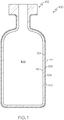
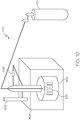
- FIG. 1 schematically depicts a cross section of a coated glass article, specifically a coated glass container 100.
- the coated glass container 100 comprises a glass body 102 and a low-friction coating 120.
- the glass body 102 has a glass container wall 104 extending between an exterior surface 108 (i.e., a first surface) and an interior surface 110 (i.e., a second surface).
- the interior surface 110 of the glass container wall 104 defines an interior volume 106 of the coated glass container 100.
- a low-friction coating 120 is positioned on at least a portion of the exterior surface 108 of the glass body 102. In some embodiments, the low-friction coating 120 may be positioned on substantially the entire exterior surface 108 of the glass body 102.
- the low-friction coating 120 has an outer surface 122 and a glass body contacting surface 124 at the interface of the glass body 102 and the low-friction coating 120.
- the low-friction coating 120 may be bonded to the glass body 102 at the exterior surface 108.
- the coated glass container 100 is a pharmaceutical package.
- the glass body 102 may be in the shape of a vial, ampoule, ampul, bottle, flask, phial, beaker, bucket, carafe, vat, syringe body.
- the coated glass container 100 may be used for containing any composition, and in one embodiment, may be used for containing a pharmaceutical composition.
- a pharmaceutical composition may include any chemical substance intended for use in the medical diagnosis, cure, treatment, or prevention of disease. Examples of pharmaceutical compositions include, but are not limited to, medicines, drugs, medications, medicaments, remedies.
- the pharmaceutical composition may be in the form of a liquid, solid, gel, suspension, powder.
- the low-friction coating 120 comprises a bi-layered structure.
- FIG. 2 shows a cross section of a coated glass container 100, where the low-friction coating comprises a polymer layer 170 and a coupling agent layer 180.
- a polymer chemical composition may be contained in polymer layer 170 and a coupling agent may be contained in a coupling agent layer 180.
- the coupling agent layer 180 may be in direct contact with the exterior surface 108 of the glass container wall 104.
- the polymer layer 170 may be in direct contact with the coupling agent layer 180 and may form the outer surface 122 of the low-friction coating 120.
- the coupling agent layer 180 is bonded to the glass wall 104 and the polymer layer 170 is bonded to the coupling agent layer 180 at an interface 174.
- the low-friction coating 120 may not include a coupling agent, and the polymer chemical composition may be disposed in a polymer layer 170 in direct contact with the exterior surface 108 of the of the glass container wall 104.
- the polymer chemical composition and coupling agent may be substantially mixed in a single layer.
- the polymer layer may be positioned over the coupling agent layer, meaning that the polymer layer 170 is in an outer layer relative to the coupling agent layer 180, and the glass wall 104.
- a first layer positioned "over" a second layer means that the first layer could be in direct contact with the second layer or separated from the second layer, such as with a third layer disposed between the first and second layers.
- the low-friction coating 120 may further comprise an interface layer 190 positioned between the coupling agent layer 180 and the polymer layer 170.
- the interface layer 190 may comprise one or more chemical compositions of the polymer layer 170 bound with one or more of the chemical compositions of the coupling agent layer 180.
- the interface of the coupling agent layer and polymer layer forms an interface layer 190 where bonding occurs between the polymer chemical composition and the coupling agent.
- the low-friction coating 120 applied to the glass body 102 may have a thickness of less than about 100 ⁇ m or even less than or equal to about 1 ⁇ m. In some embodiments, the thickness of the low-friction coating 120 may be less than or equal to about 100 nm thick. In other embodiments, the low-friction coating 120 may be less than about 90 nm thick, less than about 80 nm thick, less than about 70 nm thick, less than about 60 nm thick, less than about 50 nm, or even less than about 25 nm thick. In some embodiments, the low-friction coating 120 may not be of uniform thickness over the entirety of the glass body 102.
- the coated glass container 100 may have a thicker low-friction coating 120 in some areas, due to the process of contacting the glass body 102 with one or more coating solutions that form the low-friction coating 120.
- the low-friction coating 120 may have a non-uniform thickness.
- the coating thickness may be varied over different regions of a coated glass container 100, which may promote protection in a selected region.
- each layer may have a thickness of less than about 100 ⁇ m or even less than or equal to about 1 ⁇ m. In some embodiments, the thickness of each layer may be less than or equal to about 100 nm. In other embodiments, each layer may be less than about 90 nm thick, less than about 80 nm thick, less than about 70 nm thick, less than about 60 nm thick, less than about 50 nm, or even less than about 25 nm thick.
- the low-friction coating 120 comprises a coupling agent.
- the coupling agent may improve the adherence or bonding of the polymer chemical composition to the glass body 102, and is generally disposed between the glass body 102 and the polymer chemical composition or mixed with the polymer chemical composition.
- Adhesion refers to the strength of adherence or bonding of the low friction coating prior to and following a treatment applied to the coated glass container, such as a thermal treatment. Thermal treatments include, without limitation, autoclaving, depyrogenation, lyophilization.
- the coupling agent may comprise at least one silane chemical composition.
- a "silane" chemical composition is any chemical composition comprising a silane moiety, including functional organosilanes, as well as silanols formed from silanes in aqueous solutions.
- the silane chemical compositions of the coupling agent may be aromatic or aliphatic.
- the at least one silane chemical composition may comprise an amine moiety, such as a primary amine moiety or a secondary amine moiety.
- the coupling agent may comprise hydrolysates and/or oligomers of such silanes, such as one or more silsesquioxane chemical compositions that are formed from the one or more silane chemical compositions.
- the silsesquioxane chemical compositions may comprise a full cage structure, partial cage structure, or no cage structure.
- the coupling agent may comprise any number of different chemical compositions, such as one chemical composition, two different chemical compositions, or more than two different chemical compositions including oligomers formed from more than one monomeric chemical composition.
- the coupling agent may comprise at least one of (1) a first silane chemical composition, hydrolysate thereof, or oligomer thereof, and (2) a chemical composition formed from the oligomerization of at least the first silane chemical composition and a second silane chemical composition.
- the coupling agent comprises a first and second silane.
- a "first" silane chemical composition and a "second" silane chemical composition are silanes having different chemical compositions.
- the first silane chemical composition may be an aromatic or an aliphatic chemical composition, may optionally comprise an amine moiety, and may optionally be an alkoxysilane.
- the second silane chemical composition may be an aromatic or an aliphatic chemical composition, may optionally comprise an amine moiety, and may optionally be an alkoxysilane.
- the coupling agent may comprise a silane chemical composition, hydrolysate thereof, or oligomer thereof.
- the coupling agent may comprise at least one of (1) a mixture of the first silane chemical composition and a second silane chemical composition, and (2) a chemical composition formed from the oligomerization of at least the first silane chemical composition and the second silane chemical composition.
- the first silane chemical composition, second silane chemical composition, or both may be aromatic chemical compositions.
- an aromatic chemical composition contains one or more six-carbon rings characteristic of the benzene series and related organic moieties.
- the aromatic silane chemical composition may be an alkoxysilane such as, but not limited to, a dialkoxysilane chemical composition, hydrolysate thereof, or oligomer thereof, or a trialkoxysilane chemical composition, hydrolysate thereof, or oligomer thereof.
- the aromatic silane may comprise an amine moiety, and may be an alkoxysilane comprising an amine moiety.
- the aromatic silane chemical composition may be an aromatic alkoxysilane chemical composition, an aromatic acyloxysilane chemical composition, an aromatic halogen silane chemical composition, or an aromatic amino silane chemical composition.
- the aromatic silane chemical composition may be selected from the group consisting of aminophenyl, 3-(m-aminophenoxy) propyl, N-phenylaminopropyl, or (chloromethy) phenyl substituted alkoxy, acyloxy, halogen, or amino silanes.
- the aromatic alkoxysilane may be, but is not limited to, aminophenyltrimethoxy silane (sometimes referred to herein as "APhTMS"), aminophenyldimethoxy silane, aminophenyltriethoxy silane, aminophenyldiethoxy silane, 3-(m-aminophenoxy) propyltrimethoxy silane, 3-(m-aminophenoxy) propyldimethoxy silane, 3-(m-aminophenoxy) propyltriethoxy silane, 3-(m-aminophenoxy) propyldiethoxy silane, N-phenylaminopropyltrimethoxysilane, N-phenylaminopropyldimethoxysilane, N-phenylaminopropyltriethoxysilane, N-phenylaminopropyldiethoxysilane, hydrolysates thereof, or oligomerized chemical composition thereof.
- the aromatic silane chemical composition is, but is not limited
- the first silane chemical composition, second silane chemical composition, or both may be aliphatic chemical compositions.
- an aliphatic chemical composition is non-aromatic, such as a chemical composition having an open chain structure, such as, but not limited to, alkanes, alkenes, and alkynes.
- the coupling agent may comprise a chemical composition that is an alkoxysilane and may be an aliphatic alkoxysilane such as, but not limited to, a dialkoxysilane chemical composition, a hydrolysate thereof, or an oligomer thereof, or a trialkoxysilane chemical composition, a hydrolysate thereof, or an oligomer thereof.
- the aliphatic silane may comprise an amine moiety, and may be an alkoxysilane comprising an amine moiety, such as an aminoalkyltrialkoxysilane.
- an aliphatic silane chemical composition may be selected from the group consisting of 3-aminopropyl, N-(2-aminoethyl)-3-aminopropyl, vinyl, methyl, N-phenylaminopropyl, (N-phenylamino)methyl, N-(2-Vinylbenzylaminoethyl)-3-aminopropyl substituted alkoxy, acyloxy, halogen, or amino silanes, hydrolysates thereof, or oligomers thereof.
- Aminoalkyltrialkoxysilanes include, but are not limited to, 3-aminopropyltrimethoxy silane (sometimes referred to herein as "GAPS"), 3-aminopropyldimethoxy silane, 3-aminopropyltriethoxy silane, 3-aminopropyldiethoxy silane, N-(2-aminoethyl)-3-aminopropyltrimethoxysilane, N-(2-aminoethyl)-3-aminopropyldimethoxysilane, N-(2-aminoethyl)-3-aminopropyltriethoxysilane, N-(2-aminoethyl)-3-aminopropyldiethoxysilane, hydrolysates thereof, and oligomerized chemical composition thereof.
- GAPS 3-aminopropyltrimethoxy silane
- 3-aminopropyltriethoxy silane sometimes referred to herein
- the aliphatic alkoxysilane chemical composition may not contain an amine moiety, such as an alkyltrialkoxysilane or alkylbialkoxysilane.
- alkyltrialkoxysilanes or alkylbialkoxysilanes include, but are not limited to, vinyltrimethoxy silane, vinyldimethoxy silane, vinyltriethoxy silane, vinyldiethoxy silane, methyltrimethoxysilane, methyltdimethoxysilane, methyltriethoxysilane, methyldiethoxysilane, hydrolysates thereof, or oligomerized chemical composition thereof.
- the aliphatic silane chemical composition is 3-aminopropyltrimethoxy silane.
- the coupling agent may improve the thermal stability of the low-friction coating 120.
- combinations of aromatic silanes and aliphatic silanes such as those described above, improve the thermal stability of the low-friction coating, thereby producing a coating which retains its the mechanical properties, such as coefficient of friction and adhesion performance following a heat treatment at elevated temperatures.
- the coupling agent comprises a combination of aromatic and aliphatic silanes.
- the ratio of aliphatic silanes to aromatic silanes may be from about 1:3 to about 1:0.2.
- the ratio by weight of the two chemical compositions may be any ratio, such as a weight ratio of a first silane chemical composition to a second silane chemical composition (first silane:second silane) of about 0.1:1 to about 10:1.
- the ration may be from 0.5:1 to about 2:1, such as 2:1, 1:1, 0.5:1.
- the coupling agent may comprise combinations of multiple aliphatic silanes and/or multiple aromatic silanes, which could be applied to the glass container in one or multiple steps with or without organic or inorganic fillers.
- the coupling agent comprises oligomers, such as silsesquioxanes, formed from both the aliphatic and aromatic silanes.
- the first silane chemical composition is an aromatic silane chemical composition and the second silane chemical composition is an aliphatic silane chemical composition.
- the first silane chemical composition is an aromatic alkoxysilane chemical composition comprising at least one amine moiety and the second silane chemical composition is an aliphatic alkoxysilane chemical composition comprising at least one amine moiety.
- the coupling agent comprises an oligomer of one or more silane chemical compositions, wherein the oligomer is a silsesquioxane chemical composition and at least one of the silane chemical compositions comprises at least one aromatic moiety and at least one amine moiety.
- the first silane chemical composition is aminophenyltrimethoxy silane and the second silane chemical composition is 3-aminopropyltrimethoxy silane.
- the ratio of aromatic silane to aliphatic silane may be about 1:1.
- the coupling agent comprises an oligomer formed from aminophenyltrimethoxy and 3-aminopropyltrimethoxy.
- the coupling agent may comprise both a mixture of aminophenyltrimethoxy and 3-aminopropyltrimethoxy and oligomers formed from the two.
- the coupling agent may comprise a chemical composition that is an aminoalkylsilsesquioxane.
- the coupling agent comprises aminopropylsilsesquioxane (APS) oligomer (commercially available as an aqueous solution from Gelest).
- APS aminopropylsilsesquioxane
- the aromatic silane chemical composition is a chlorosilane chemical composition.
- the coupling agent may comprise chemical composition that are hydrolyzed analogs of aminoalkoxysilanes such as, but not limited to, (3-Aminopropyl)silantriol, N-(2-Aminoethyl)-3-aminopropyl-silantriol and/or mixtures thereof.
- the coupling agent may be an inorganic material, such as metal and/or a ceramic film.
- suitable inorganic materials used as the coupling agent include titanates, zirconates, tin, titanium, and/or oxides thereof.
- the coupling agent is applied to the exterior surface 108 of the glass body 102 by contacting with the diluted coupling agent by a submersion process.
- the coupling agent may be mixed in a solvent when applied to the glass body 102.
- the coupling agent may be applied to the glass body 102 by a spray or other suitable means.
- the glass body 102 with coupling agent may then be dried at around 120°C for about 15 min, or any time and temperature sufficient to adequately liberate the water and/or other organic solvents present on the exterior surface 108 of the glass container wall 104.
- the coupling agent is positioned on the glass container as a coupling agent layer 180 and is applied as a solution comprising about 0.5 wt% of a first silane and about 0.5 wt% of a second silane (total 1 wt% silane) mixed with at least one of water and an organic solvent, such as, but not limited to, methanol.
- an organic solvent such as, but not limited to, methanol.
- the total silane concentration in the solution may be more or less than about 1 wt%, such as from about 0.1 wt% to about 10 wt%, from about 0.3 wt% to about 5.0 wt%, or from about 0.5 wt% to about 2.0 wt%.
- the weight ratio of organic solvent to water may be from about 90:10 to about 10:90, and, in one embodiment, may be about 75:25.
- the weight ratio of silane to solvent may affect the thickness of the coupling agent layer, where increased percentages of silane chemical composition in the coupling agent solution may increase the thickness of the coupling agent layer 180.
- other variables may affect the thickness of the coupling agent layer 180 such as, but not limited, the specifics of the dip coating process, such as the withdraw speed from the bath. For example, a faster withdraw speed may form a thinner coupling agent layer 180.
- the coupling agent layer 180 may be applied as a solution comprising 0.1 vol% of a commercially available aminopropylsilsesquioxane oligomer. Coupling agent layer solutions of other concentrations may be used, including but not limited to, 0.01-10.0 vol% aminopropylsilsesquioxane oligomer solutions.
- the low friction coating also includes a polymer chemical composition.
- the polymer chemical composition may be a thermally stable polymer or mixture of polymers, such as but not limited to, polyimides, polybenzimidazoles, polysulfones, polyetheretheketones, polyetherimides, polyamides, polyphenyls, polybenzothiazoles, polybenzoxazoles, polybisthiazoles, and polyaromatic heterocyclic polymers with and without organic or inorganic fillers.
- the polymer chemical composition may be formed from other thermally stable polymers, such as polymers that do not degrade at temperatures in the range of from 200°C to 400°C, including 250°C, 300°C, and 350°C. These polymers may be applied with or without a coupling agent.
- the polymer chemical composition is a polyimide chemical composition.
- the polyimide composition may be derived from a polyamic acid, which is formed in a solution by the polymerization of monomers.
- a polyamic acid is Novastrat® 800 (commercially available from NeXolve).
- a curing step imidizes the polyamic acid to form the polyimide.
- the polyamic acid may be formed from the reaction of a diamine monomer, such as a diamine, and an anhydride monomer, such as a dianhydride.
- polyimide monomers are described as diamine monomers and dianhydride monomers.
- a diamine monomer comprises two amine moieties
- any monomer comprising at least two amine moieties may be suitable as a diamine monomer.
- a dianhydride monomer comprises two anhydride moieties
- any monomer comprising at least two anhydride moieties may be suitable as a dianhydride monomer.
- the reaction between the anhydride moieties of the anhydride monomer and amine moieties of the diamine monomer forms the polyamic acid.
- a polyimide chemical composition that is formed from the polymerization of specified monomers refers to the polyimide that is formed following the imidization of a polyamic acid that is formed from those specified monomers.
- the molar ratio of the total anhydride monomers and diamine monomers may be about 1:1.
- the polyimide may be formed from only two distinct chemical compositions (one anhydride monomer and one diamine monomer), at least one anhydride monomer may be polymerized and at least one diamine monomer may be polymerized to from the polyimide.
- one anhydride monomer may be polymerized with two different diamine monomers. Any number of monomer specie combinations may be used.
- the ratio of one anhydride monomer to a different anhydride monomer, or one or more diamine monomer to a different diamine monomer may be any ratio, such as between about 1:0.1 to 0.1:1, such as about 1:9, 1:4, 3:7, 2:3:, 1:1, 3:2, 7:3, 4:1 or 1:9.
- the anhydride monomer from which, along with the diamine monomer, the polyimide is formed may comprise any anhydride monomer.
- the anhydride monomer comprises a benzophenone structure.
- benzophenone-3,3',4,4'-tetracarboxylic dianhydride may be at least one of the anhydride monomer from which the polyimide is formed.
- the diamine monomer may have an anthracene structure, a phenanthrene structure, a pyrene structure, or a pentacene structure, including substituted versions of the above mentioned dianhydrides.
- the diamine monomer from which, along with the anhydride monomer, the polyimide is formed may comprise any diamine monomer.
- the diamine monomer comprises at least one aromatic ring moiety.
- FIGS. 4 and 5 show examples of diamine monomers that, along with one or more selected anhydride monomer, may form the polyimide comprising the polymer chemical composition.
- the diamine monomer may have one or more carbon molecules connecting two aromatic ring moieties together, as shown in FIG. 4 , wherein R of FIG. 5 corresponds to an alkyl moiety comprising one or more carbon atoms.
- the diamine monomer may have two aromatic ring moieties that are directly connected and not separated by at least one carbon molecule, as shown in FIG. 5 .
- the diamine monomer may have one or more alkyl moieties, as represented by R' and R" in FIGS. 4 and 5 .
- R' and R" may represent an alkyl moiety such as methyl, ethyl, propyl, or butyl moieties, connected to one or more aromatic ring moieties.
- the diamine monomer may have two aromatic ring moieties wherein each aromatic ring moiety has an alkyl moiety connected thereto and adjacent an amine moiety connected to the aromatic ring moiety.
- R' and R" in both FIGS. 4 and 5 may be the same chemical moiety or may be different chemical moieties.
- R' and/or R" in both FIGS. 4 and 5 may represent no atoms at all.
- a first diamine monomer comprises two aromatic ring moieties that are directly connected and not separated by a linking carbon molecule
- a second diamine monomer comprises two aromatic ring moieties that are connected with at least one carbon molecule connecting the two aromatic ring moieties.
- the first diamine monomer, the second diamine monomer, and the anhydride monomer have a molar ratio (first diamine monomer : second diamine monomer : anhydride monomer) of about 0.465:0.035:0.5.
- the ratio of the first diamine monomer and the second diamine monomer may vary in a range of about 0.01:0.49 to about 0.40:0.10, while the anhydride monomer ratio remains at about 0.5.
- the polyimide composition is formed from the polymerization of at least a first diamine monomer, a second diamine monomer, and an anhydride monomer, wherein the first and second diamine monomers are different chemical compositions.
- the anhydride monomer is a benzophenone
- the first diamine monomer comprises two aromatic rings directly bonded together
- the second diamine monomer comprises two aromatic rings bonded together with at least one carbon molecule connecting the first and second aromatic rings.
- the first diamine monomer, the second diamine monomer, and the anhydride monomer may have a molar ratio (first diamine monomer : second diamine monomer : anhydride monomer) of about 0.465:0.035:0.5.
- the first diamine monomer is ortho-Tolidine
- the second diamine monomer is 4,4'-methylene-bis(2-methylaniline)
- the anhydride monomer is benzophenone-3,3',4,4'-tetracarboxylic dianhydride.
- the first diamine monomer, the second diamine monomer, and the anhydride monomer may have a molar ratio (first diamine monomer : second diamine monomer : anhydride monomer) of about 0.465:0.035:0.5.
- the polyimide may be formed from the polymerization of one or more of: bicyclo[2.2.1]heptane-2,3,5,6-tetracarboxylic dianhydride, cyclopentane-1,2,3,4-tetracarboxylic 1,2;3,4-dianhydride, bicyclo[2.2.2]octane-2,3,5,6-tetracarboxylic dianhydride, 4arH,8acH)-decahydro- 1t,4t:5c,8c-dimethanonaphthalene-2t,3t,6c,7c-tetracarboxylic 2,3:6,7-dianhydride, 2c,3c,6c,7c-tetracarboxylic 2,3:6,7-dianhydride, 5-endo-carboxymethylbicyclo[2.2.1]-heptane-2-exo,3-exo,5-exo-tricarboxylic acid 2,3:5,5-dianhydride,
- FIG. 6 depicts the chemical structure of some suitable monomers that may be used to form a polyimide coating applied to the glass body 102.
- the polyamic acid solution from which the polyimide is formed may comprise poly (pyromellitic dianhydride-co-4,4'-oxydianiline) amic acid (commercially available from Aldrich).
- the polymer chemical composition may comprise a fluoropolymer.
- the fluoropolymer may be a copolymer wherein both monomers are highly fluorinated. Some of the monomers of the fluoropolymer may be fluoroethylene.
- the polymer chemical composition comprises an amorphous fluoropolymer, such as, but not limited to, Teflon AF (commercially available from DuPont).
- the polymer chemical composition comprises perfluoroalkoxy (PFA) resin particles, such as, but not limited to, Teflon PFA TE-7224 (commercially available from DuPont).
- the polymer chemical composition may comprise a silicone resin.
- the silicone resin may be a highly branched 3-dimensional polymer which is formed by branched, cage-like oligosiloxanes with the general formula of R n Si(X) m O y , where R is a non reactive substituent, usually methyl or phenyl, and X is OH or H. While not wishing to be bound by theory, it is believed that curing of the resin occurs through a condensation reaction of Si-OH moieties with a formation of Si-O-Si bonds.
- the silicone resin may have at least one of four possible functional siloxane monomeric units, which include M-resins, D-resins, T-resins, and Q-resins, wherein M-resins refer to resins with the general formula R 3 SiO, D-resins refer to resins with the general formula R 2 SiO 2 , T-resins refer to resins with the general formula RSiO 3 , and Q-resins refer to resins with the general formula SiO 4 (a fused quartz).
- resins are made of D and T units (DT resins) or from M and Q units (MQ resins). In other embodiments, other combinations (MDT, MTQ, QDT) are also used.
- the polymer chemical composition comprises phenylmethyl silicone resins due to their higher thermal stability compared to methyl or phenyl silicone resins.
- the ratio of phenyl to methyl moieties in the silicone resins may be varied in the polymer chemical composition. In one embodiment, the ratio of phenyl to methyl is about 1.2. In another embodiment, the ratio of phenyl to methyl is about 0.84. In other embodiments, the ratio of phenyl to methyl moieties may be about 0.5, 0.6, 0.7, 0.8, 0.9, 1.0, 1.1, 1.3, 1.4, or 1.5.
- the silicone resin is DC 255 (commercially available from Dow Corning).
- the silicone resin is DC806A (commercially available from Dow Corning).
- the polymer chemical composition may comprise any of the DC series resins (commercially available for Dow Corning), and/or Hardsil Series AP and AR resins (commercially available from Gelest).
- the silicone resins can be used without coupling agent or with coupling agent.
- the polymer chemical composition may comprise silsesquioxane-based polymers, such as but not limited to T-214 (commercially available from Honeywell), SST-3M01 (commercially available from Gelest), POSS Imiclear (commercially available from Hybrid Plastics), and FOX-25 (commercially available from Dow Corning).
- the polymer chemical composition may comprise a silanol moiety.
- the low-friction coating 120 may be applied in a multi stage process, wherein the glass body 102 is contacted with the coupling agent solution to form the coupling agent layer 180 (as described above), and dried, and then contacted with a polymer chemical composition solution, such as a polymer or polymer precursor solution, such as by a submersion process, or alternatively, the polymer chemical composition layer 170 may be applied by a spray or other suitable means, and dried, and then cured at high temperatures.
- the polymer chemical composition of the polymer layer 170 may be directly applied to the exterior surface 108 of the glass body 102.
- the polymer chemical composition and the coupling agent may be mixed in the low-friction coating 120, and a solution comprising the polymer chemical composition and the coupling agent may be applied to the glass body 102 in a single coating step.
- the polymer chemical composition comprises a polyimide wherein a polyamic acid solution is applied over the coupling agent layer 180.
- a polyamic acid derivative may be used, such as, for example, a polyamic acid salt, a polyamic acid ester, or the like.
- the polyamic acid solution may comprise a mixture of 1 vol% polyamic acid and 99 vol% organic solvent.
- the organic solvent may comprise a mixture of toluene and at least one of N,N-Dimethylacetamide (DMAc), N,N-Dimethylformamide (DMF), and 1-Methyl-2-pyrrolidinone (NMP) solvents, or a mixture thereof.
- the organic solvent solution comprises about 85 vol% of at least one of DMAc, DMF, and NMP, and about 15 vol% toluene. However, other suitable organic solvents may be used.
- the coated glass container 100 may then be dried at around 150°C for about 20 minutes, or any time and temperature sufficient to adequately liberate the organic solvent present in the low-friction coating 120.
- the coated glass container 100 may be cured at high temperatures.
- the coated glass container 100 may be cured at 300°C for about 30 minutes or less, or may be cured at a temperature higher than 300°C, such as at least 320°C, 340°C, 360°C, 380°C, or 400°C for a shorter time.
- the curing step imidizes the polyamic acid in the polymer layer 170 by reaction of carboxylic acid moieties and amide moieties to create a polymer layer 170 comprising a polyimide.
- the curing may also promote bonds between the polyimide and the coupling agent.
- the coated glass container 100 is then cooled to room temperature.
- the curing of the coupling agent, polymer chemical composition, or both drives off volatile materials, such as water and other organic molecules.
- volatile materials such as water and other organic molecules.
- these volatile materials that are liberated during curing are not present when the article, if used as a container, is thermally treated (such as for depyrogenation) or contacted by the material in which it is a package for, such as a pharmaceutical.
- the curing processes described herein are separate heating treatments than other heating treatments described herein, such as those heating treatments similar or identical to processes in the pharmaceutical packaging industry, such as depyrogenation or the heating treatments used to define thermal stability, as described herein.
- the glass containers to which the low-friction coating 120 may be applied may be formed from a variety of different glass compositions.
- the specific composition of the glass article may be selected according to the specific application such that the glass has a desired set of physical properties.
- the glass containers may be formed from a glass composition which has a coefficient of thermal expansion in the range from about 25x10 -7 /°C to 80x10 -7 /°C .
- the glass body 102 is formed from alkali aluminosilicate glass compositions which are amenable to strengthening by ion exchange.
- Such compositions generally include a combination of SiO 2 , Al 2 O 3 , at least one alkaline earth oxide, and one or more alkali oxides, such as Na 2 O and/or K 2 O.
- the glass composition may be free from boron and compounds containing boron.
- the glass compositions may further comprise minor amounts of one or more additional oxides such as, for example, SnO 2 , ZrO 2 , ZnO, TiO 2 , As 2 O 3 . These components may be added as fining agents and/or to further enhance the chemical durability of the glass composition.
- the glass surface may comprise a metal oxide coating comprising SnO 2 , ZrO 2 , ZnO, TiO 2 , As 2 O 3 .
- the glass body 102 is strengthened such as by ion-exchange strengthening, herein referred to as "ion-exchanged glass".
- the glass body 102 may have a compressive stress of greater than or equal to about 300 MPa or even greater than or equal to about 350 MPa.
- the compressive stress may be in a range from about 300 MPa to about 900 MPa.
- the compressive stress in the glass may be less than 300 MPa or greater than 900 MPa.
- the glass body 102 may have a depth of layer greater than or equal to 20 ⁇ m.
- the depth of layer may be greater than 50 ⁇ m or even greater than or equal to 75 ⁇ m. In still other embodiments, the depth of the layer may be up to or greater than 100 ⁇ m.
- the ion-exchange strengthening may be performed in a molten salt bath maintained at temperatures from about 350°C to about 500°C. To achieve the desired compressive stress, the glass container (uncoated) may be immersed in the salt bath for less than about 30 hours or even less than about 20 hours. For example, in one embodiment the glass container is immersed in a 100% KNO 3 salt bath at 450°C for about 8 hours.
- the glass body 102 may be formed from an ion exchangeable glass composition described in pending U.S. Patent Application Serial No. 13/660894 filed October 25, 2012 and entitled "Glass Compositions with Improved Chemical and Mechanical Durability” assigned to Corning, Incorporated.
- coated glass containers 100 described herein may be formed from other glass compositions including, without limitation, ion-exchangeable glass compositions and non-ion exchangeable glass compositions.
- the glass container may be formed from Type IB glass compositions such as, for example, Schott Type IB aluminosilicate glass.
- the glass article may be formed from a glass composition which meets the criteria for pharmaceutical glasses described by regulatory agencies such as the USP (United States Pharmacopoeia), the EP (European Pharmacopeia), and the JP (Japanese Pharmacopeia) based on their hydrolytic resistance.
- USP 660 and EP 7 borosilicate glasses meet the Type I criteria and are routinely used for parenteral packaging. Examples of borosilicate glass include, but not limited to Corning® Pyrex® 7740, 7800 and Wheaton 180, 200, and 400, Schott Duran, Schott Fiolax, KIMAX® N-51A, Gerrescheimer GX-51 Flint and others.
- Soda-lime glass meets the Type III criteria and is acceptable in packaging of dry powders which are subsequently dissolved to make solutions or buffers.
- Type III glasses are also suitable for packaging liquid formulations that prove to be insensitive to alkali.
- Examples of Type III soda lime glass include Wheaton 800 and 900.
- Dealkalized soda-lime glasses have higher levels of sodium hydroxide and calcium oxide and meet the Type II criteria. These glasses are less resistant to leaching than Type I glasses but more resistant than Type III glasses.
- Type II glasses can be used for products that remain below a pH of 7 for their shelf life. Examples include ammonium sulfate treated soda lime glasses.
- These pharmaceutical glasses have varied chemical compositions and have a coefficient of linear thermal expansion (CTE) in the range of 20-85 x 10 -7 °C -1 .
- the glass body 102 of the coated glass containers 100 may take on a variety of different forms.
- the glass bodies described herein may be used to form coated glass containers 100 such as vials, ampoules, cartridges, syringe bodies and/or any other glass container for storing pharmaceutical compositions.
- the ability to chemically strengthen the glass containers prior to coating can be utilized to further improve the mechanical durability of the glass containers.
- the glass containers may be ion exchange strengthened prior to application of the low-friction coating.
- other strengthening methods such as heat tempering, flame polishing, and laminating, as described in U.S. Patent No. 7,201,965 , could be used to strengthen the glass before coating.
- the coupling agent comprises a silane chemical composition, such as an alkoxysilane, which may improve the adhesion of the polymer chemical composition to the glass body.
- a silane chemical composition such as an alkoxysilane
- alkoxysilane molecules hydrolyze rapidly in water forming isolated monomers, cyclic oligomers, and large intramolecular cyclics.
- the control over which species predominates may be determined by silane type, concentration, pH, temperature, storage condition, and time. For example, at low concentrations in aqueous solution, aminopropyltrialkoxysilane (APS) may be stable and form trisilanol monomers and very low molecular weight oligomeric cyclics.
- APS aminopropyltrialkoxysilane
- the reaction of one or more silanes chemical compositions to the glass body may involve several steps. As shown in FIG. 31 , in some embodiments, following hydrolysis of the silane chemical composition, a reactive silanol moiety may be formed, which can condense with other silanol moieties, for example, those on the surface of a substrate, such as a glass body. After the first and second hydrolysable moieties are hydrolyzed, a condensation reaction may be initialized. In some embodiments, the tendency toward self condensation can be controlled by using fresh solutions, alcoholic solvents, dilution, and by careful selection of pH ranges.
- silanetriols are most stable at pH 3-6, but condense rapidly at pH 7-9.3, and partial condensation of silanol monomers may produce silsesquioxanes.
- the silanol moieties of the formed species may form hydrogen bonds with silanol moieties on the substrate, and during drying or curing a covalent bond may be formed with the substrate with elimination of water.
- a moderate cure cycle 110°C for 15 min
- the one or more silane chemical compositions of the coupling agent may comprise an amine moiety. Still without being bound by theory, it is believed that this amine moiety may act as a base catalyst in the hydrolysis and cocondensation polymerization and enhance the adsorption rate of the silanes having an amine moiety on a glass surface. It may also create a high pH (9.0-10.0) in aqueous solution that conditions the glass surface and increases density of surface silanol moieties. Strong interaction with water and protic solvents maintains solubility and stability of a silane having an amine moiety chemical composition, such as APS.
- this amine moiety may act as a base catalyst in the hydrolysis and cocondensation polymerization and enhance the adsorption rate of the silanes having an amine moiety on a glass surface. It may also create a high pH (9.0-10.0) in aqueous solution that conditions the glass surface and increases density of surface silanol moieties. Strong interaction with water and protic solvent
- the glass body may comprise ion-exchanged glass and the coupling agent may be a silane.
- adhesion of the low-friction coating to an ion-exchanged glass body may stronger than adhesion of the low-friction coating to a non-ion-exchanged glass body. It is believed, without being bound by theory, that any of several aspects of ion-exchanged glass may promote bonding and/or adhesion, as compared with non-ion-exchanged glass. First, ion-exchanged glass may have enhanced chemical/hydrolytic stability that may affect stability of the coupling agent and/or its adhesion to glass surface.
- Non-ion-exchanged glass typically has inferior hydrolytic stability and under humid and/or elevated temperature conditions, alkali metals could migrate out of the glass body to the interface of the glass surface and coupling agent layer (if present), or even migrate into the coupling agent layer, if present. If alkali metals migrate, as described above, and there is a change in pH, hydrolysis of Si-O-Si bonds at the glass/coupling agent layer interface or in the coupling agent layer itself may weaken either the coupling agent mechanical properties or its adhesion to the glass.
- ion-exchanged glasses are exposed to strong oxidant baths, such as potassium nitrite baths, at elevated temperatures, such as 400°C to 450°C, and removed, organic chemical compositions on the surface of the glass are removed, making it particularly well suited for silane coupling agents without further cleaning.
- a non-ion-exchanged glass may have to be exposed to an additional surface cleaning treatment, adding time and expense to the process.
- the coupling agent may comprise at least one silane comprising an amine moiety and the polymer chemical composition may comprise a polyimide chemical composition.
- the first step is formation of a polyamic acid salt between a carboxyl moiety of the polyamic acid and the amine moiety.
- the second step is thermal conversion of the salt into an amide moiety.
- the thirds step is further conversion of the amide moiety into an imide moiety with scission of the polymer amide bonds.
- the result is a covalent imide attachment of a shortened polymer chain (polyimide chain) to an amine moiety of the coupling agent, as shown in FIG. 32 .
- FIG. 7 contains a process flow diagram 500 of a method for producing a coated glass container 100 having a low-friction coating and FIG. 8 schematically depicts the process described in the flow diagram.
- glass tube stock 1000 formed from an ion-exchangeable glass composition is initially shaped into glass containers 900 (specifically glass vials in the embodiment depicted) using conventional shaping and forming techniques.
- the glass containers 900 are loaded into a magazine 604 using a mechanical magazine loader 602.
- the magazine loader 602 may be a mechanical gripping device, such as a caliper, which is capable of gripping multiple glass containers at one time. Alternatively, the gripping device may utilize a vacuum system to grip the glass containers 900.
- the magazine loader 602 may be coupled to a robotic arm or other, similar device capable of positioning the magazine loader 602 with respect to the glass containers 900 and the magazine 604.
- the magazine 604 loaded with glass containers 900 is transferred with a mechanical conveyor, such as a conveyor belt 606, overhead crane, to a cassette loading area. Thereafter, in step 508, the magazine 604 is loaded into a cassette 608.
- the cassette 608 is constructed to hold a plurality of magazines such that a large number of glass containers can be processed simultaneously.
- Each magazine 604 is positioned in the cassette 608 utilizing a cassette loader 610.
- the cassette loader 610 may be a mechanical gripping device, such as a caliper, which is capable of gripping one or more magazines at a time. Alternatively, the gripping device may utilize a vacuum system to grip the magazines 604.
- the cassette loader 610 may be coupled to a robotic arm or other, similar device capable of positioning the cassette loader 610 with respect to the cassette 608 and the magazine 604.
- the cassette 608 containing the magazines 604 and glass containers 900 is transferred to an ion exchange station and loaded into an ion exchange tank 614 to facilitate chemically strengthening the glass containers 900.
- the cassette 608 is transferred to the ion exchange station with a cassette transfer device 612.
- the cassette transfer device 612 may be a mechanical gripping device, such as a capiler, which is capable of gripping the cassette 608. Alternatively, the gripping device may utilize a vacuum system to grip the cassette 608.
- the cassette transfer device 612 and attached cassette 608 may be automatically conveyed from the cassette loading area to the ion exchange station with an overhead rail system, such as a gantry crane.
- the cassette transfer device 612 and attached cassette 608 may be conveyed from the cassette loading area to the ion exchange station with a robotic arm.
- the cassette transfer device 612 and attached cassette 608 may be conveyed from the cassette loading area to the ion exchange station with a conveyor and, thereafter, transferred from the conveyor to the ion exchange tank 614 with a robotic arm or an overhead crane.
- the cassette 608 and the glass containers 900 contained therein may be preheated prior to immersing the cassette 608 and the glass containers 900 in the ion exchange tank 614.
- the cassette 608 may be preheated to a temperature greater than room temperature and less than or equal to the temperature of the molten salt bath in the ion exchange tank.
- the glass containers may be preheated to a temperature from about 300°C - 500°C.
- the ion exchange tank 614 contains a bath of molten salt 616, such as a molten alkali salt, such as KNO 3 , NaNO 3 and/or combinations thereof.
- the bath of molten salt is 100% molten KNO 3 which is maintained at a temperature greater than or equal to about 350°C and less than or equal to about 500°C.
- baths of molten alkali salt having various other compositions and/or temperatures may also be used to facilitate ion exchange of the glass containers.
- the glass containers 900 are ion exchange strengthened in the ion exchange tank 614. Specifically, the glass containers are immersed in the molten salt and held there for a period of time sufficient to achieve the desired compressive stress and depth of layer in the glass containers 900.
- the glass containers 900 may be held in the ion exchange tank 614 for a time period sufficient to achieve a depth of layer of up to about 100 ⁇ m with a compressive stress of at least about 300 MPa or even 350 MPa. The holding period may be less than 30 hours or even less than 20 hours.
- the time period with which the glass containers are held in the tank 614 may vary depending on the composition of the glass container, the composition of the bath of molten salt 616, the temperature of the bath of molten salt 616, and the desired depth of layer and the desired compressive stress.
- the cassette 608 and glass containers 900 are removed from the ion exchange tank 614 using the cassette transfer device 612 in conjunction with a robotic arm or overhead crane.
- the cassette 608 and the glass containers 900 are suspended over the ion exchange tank 614 and the cassette 608 is rotated about a horizontal axis such that any molten salt remaining in the glass containers 900 is emptied back into the ion exchange tank 614.
- the cassette 608 is rotated back to its initial position and the glass containers are allowed to cool prior to being rinsed.
- the cassette 608 and glass containers 900 are then transferred to a rinse station with the cassette transfer device 612. This transfer may be performed with a robotic arm or overhead crane, as described above, or alternatively, with an automatic conveyor such as a conveyor belt.
- the cassette 608 and glass containers 900 are lowered into a rinse tank 618 containing a water bath 620 to remove any excess salt from the surfaces of the glass containers 900.
- the cassette 608 and glass containers 900 may be lowered into the rinse tank 618 with a robotic arm, overhead crane or similar device which couples to the cassette transfer device 612.
- the cassette 608 and glass containers 900 are then withdrawn from the rinse tank 618, suspended over the rinse tank 618, and the cassette 608 is rotated about a horizontal axis such that any rinse water remaining in the glass containers 900 is emptied back into the rinse tank 618.
- the rinsing operation may be performed multiple times before the cassette 608 and glass containers 900 are moved to the next processing station.
- the cassette 608 and the glass containers 900 are dipped in a water bath at least twice.
- the cassette 608 may be dipped in a first water bath and, subsequently, a second, different water bath to ensure that all residual alkali salts are removed from the surface of the glass article.
- the water from the first water bath may be sent to waste water treatment or to an evaporator.
- a next step 516 the magazines 604 are removed from the cassette 608 with the cassette loader 610. Thereafter, in step 518, the glass containers 900 are unloaded from the magazine 604 with the magazine loader 602 and transferred to a washing station. In step 520, the glass containers are washed with a jet of de-ionized water 624 emitted from a nozzle 622.
- the jet of de-ionized water 624 may be mixed with compressed air.
- step 521 the glass containers 900 are transferred to an inspection station where the glass containers are inspected for flaws, debris, discoloration.
- the glass containers 900 are transferred to the coating station with the magazine loader 602 where the low-friction coating is applied to the glass containers 900.
- the application of the low-friction coating may include the application of a coupling agent directly to the surface of the glass container and a polymer chemical composition on the coupling agent, as described above.
- the glass containers 900 are partially immersed in a first dip tank 626 which contains the coupling agent 628 to coat the exterior surface of the glass containers with the coupling agent.
- the coupling agent may be spray applied. Thereafter, the glass containers are withdrawn from the first dip tank 626 and the coupling agent is dried.
- the glass containers 900 may be conveyed to an oven where the glass containers 900 are dried at about 120°C for 15 minutes.
- FIG. 8 While the process schematically depicted in FIG. 8 includes a step of coating the outside of the glass containers with a coupling agent, it should be understood that this step is only used for those coating compositions in which a coupling agent is needed. In other embodiments of low-friction coatings in which a coupling agent is not needed, the step of applying the coupling agent may be omitted.
- the glass containers 900 are conveyed to the coating dip tank 630 with the magazine loader 602.
- the coating dip tank 630 is filled with the polymer chemical composition coating solution 632 comprising a polymer chemical composition described herein above.
- the glass containers are at least partially immersed in the polymer chemical composition coating solution 632 to coat the polymer chemical composition onto the glass containers, either directly onto the exterior surface of the glass containers 900 or onto the coupling agent which is already coated on the glass containers 900.
- the polymer chemical composition solution is dried to remove any solvents.
- the coating solution may be dried by conveying the glass containers 900 to an oven and heating the glass containers at 150°C for 20 minutes.
- the glass containers 900 may (optionally) be re-dipped into the polymer chemical composition coating dip tank 630 to apply one or more additional layers of polymer chemical composition.
- the polymer chemical composition coating is applied to the entire external surface of the container, while in other embodiments the low-friction coating is only applied to a portion of the external surface of the container. While the coupling agent and polymer chemical composition are described herein, in some embodiments, as being applied in two separate steps, it should be understood that in an alternative embodiment, the coupling agent and low-friction coating are applied in a single step, such as when the coupling agent and the polymer chemical composition are combined in a mixture.
- the polymer chemical composition coating solution 632 is applied to the glass containers 900.
- the curing process depends on the type of polymer chemical composition coating applied to the coating process and may include thermally curing the coating, curing the coating with UV light, and/or a combination thereof.
- the polymer chemical composition coating comprises a polyimide such as the polyimide formed by the Novastrat® 800 polyamic acid coating solution described above
- the glass containers 900 are conveyed to an oven 634 where they are heated from 150°C to approximately 350°C over a period of about 5 to 30 minutes. Upon removal of the glass containers from the oven, the polymer chemical composition coating is cured thereby producing a coated glass container with a low-friction coating.
- the coated glass containers 100 are transferred to a packaging process in step 524 where the containers are filled and/or to an additional inspection station.
- Various properties of the coated glass containers may be measured when the coated glass containers are in an as-coated condition (i.e., following application of the coating without any additional treatments) or following one or more processing treatments, such as those similar or identical to treatments performed on a pharmaceutical filling line, including, without limitation, washing, lyophilization, depyrogenation, autoclaving.
- Depyrogentation is a process wherein pyrogens are removed from a substance.
- Depyrogenation of glass articles can be performed by a thermal treatment applied to a sample in which the sample is heated to an elevated temperature for a period of time.
- depyrogenation may include heating a glass container to a temperature of between about 250°C and about 380°C for a time period from about 30 seconds to about 72 hours, including, without limitation, 20 minutes, 30 minutes 40 minutes, 1 hour, 2 hours, 4 hours, 8 hours, 12 hours, 24 hours, 48 hours, and 72 hours.
- the glass container is cooled to room temperature.
- One conventional depyrogenation condition commonly employed in the pharmaceutical industry is thermal treatment at a temperature of about 250°C for about 30 minutes.
- the time of thermal treatment may be reduced if higher temperatures are utilized.
- the coated glass containers, as described herein may be exposed to elevated temperatures for a period of time.
- the elevated temperatures and time periods of heating described herein may or may not be sufficient to depyrogenate a glass container.
- it should be understood that some of the temperatures and times of heating described herein are sufficient to dehydrogenate a coated glass container, such as the coated glass containers described herein.
- the coated glass containers may be exposed to temperatures of about 260°C, about 270°C, about 280°C, about 290°C, about 300°C, about 310°C, about 320°C, about 330°C, about 340°C, about 350°C, about 360°C, about 370°C, about 380°C, about 390°C, or about 400°C, for a period of time of 30 minutes.
- lyophilization conditions i.e., freeze drying
- a sample is filled with a liquid that contains protein and then frozen at -100°C, followed by water sublimation for 20 hours at -15°C under vacuum.
- autoclave conditions refer to steam purging a sample for 10 minutes at 100°C, followed by a 20 minute dwelling period wherein the sample is exposed to a 121°C environment, followed by 30 minutes of heat treatment at 121°C.
- the coefficient of friction ( ⁇ ) of the portion of the coated glass container with the low-friction coating may have a lower coefficient of friction than a surface of an uncoated glass container formed from a same glass composition.
- a coefficient of friction ( ⁇ ) is a quantitative measurement of the friction between two surfaces and is a function of the mechanical and chemical properties of the first and second surfaces, including surface roughness, as well as environmental conditions such as, but not limited to, temperature and humidity.
- a coefficient of friction measurement for coated glass container 100 is reported as the coefficient of friction between the outer surface of a first glass container (having an outer diameter of between about 16.00 mm and about 17.00 mm) and the outer surface of second glass container which is identical to the first glass container, wherein the first and second glass containers have the same body and the same coating composition (when applied) and have been exposed to the same environments prior to fabrication, during fabrication, and after fabrication.
- the coefficient of friction refers to the maximum coefficient of friction measured with a normal load of 30 N measured on a vial-on-vial testing jig, as described herein.
- a coated glass container which exhibits a maximum coefficient of friction at a specific applied load will also exhibit the same or better (i.e., lower) maximum coefficient of friction at a lesser load. For example, if a coated glass container exhibits a maximum coefficient of friction of 0.5 or lower under an applied load of 50 N, the coated glass container will also exhibit a maximum coefficient of friction of 0.5 or lower under an applied load of 25 N.
- the coefficient of friction of the glass containers is measured with a vial-on-vial testing jig.
- the testing jig 200 is schematically depicted in FIG. 9 .
- the same apparatus may also be used to measure the frictive force between two glass containers positioned in the jig.
- the vial-on-vial testing jig 200 comprises a first clamp 212 and a second clamp 222 arranged in a cross configuration.
- the first clamp 212 comprises a first securing arm 214 attached to a first base 216.
- the first securing arm 214 attaches to the first glass container 210 and holds the first glass container 210 stationary relative to the first clamp 212.
- the second clamp 222 comprises a second securing arm 224 attached to a second base 226.
- the second securing arm 224 attaches to the second glass container 220 and holds it stationary relative to the second clamp 222.
- the first glass container 210 is positioned on the first clamp 212 and the second glass container 220 is positioned of the second clamp 222 such that the long axis of the first glass container 210 and the long axis of the second glass container 220 are positioned at about a 90° angle relative to one another and on a horizontal plane defined by the x-y axis.
- a first glass container 210 is positioned in contact with the second glass container 220 at a contact point 230.
- a normal force is applied in a direction orthogonal to the horizontal plane defined by the x-y axis.
- the normal force may be applied by a static weight or other force applied to the second clamp 222 upon a stationary first clamp 212.
- a weight may be positioned on the second base 226 and the first base 216 may be placed on a stable surface, thus inducing a measurable force between the first glass container 210 and the second glass container 220 at the contact point 230.
- the force may be applied with a mechanical apparatus, such as a UMT (universal mechanical tester) machine.
- the first clamp 212 or second clamp 222 may be moved relative to the other in a direction which is at a 45° angle with the long axis of the first glass container 210 and the second glass container 220.
- the first clamp 212 may be held stationary and the second clamp 222 may be moved such that the second glass container 220 moves across the first glass container 210 in the direction of the x-axis.
- R. L. De Rosa et al. in "Scratch Resistant Polyimide Coatings for Alumino Silicate Glass surfaces” in The Journal of Adhesion, 78: 113-127, 2002 .
- the force required to move the second clamp 222 and the normal force applied to first and second glass containers 210,220 are measured with load cells and the coefficient of friction is calculated as the quotient of the frictive force and the normal force.
- the jig is operated in an environment of 25°C and 50% relative humidity.
- the portion of the coated glass container with the low-friction coating has a coefficient of friction of less than or equal to about 0.7 relative to a like-coated glass container, as determined with the vial-on-vial jig described above. In other embodiments, the coefficient of friction may be less than or equal to about 0.6, or even less than or equal to about 0.5. In some embodiments, the portion of the coated glass container with the low-friction coating has a coefficient of friction of less than or equal to about 0.4 or even less than or equal to about 0.3. Coated glass containers with coefficients of friction less than or equal to about 0.7 generally exhibit improved resistance to frictive damage and, as a result, have improved mechanical properties. For example, conventional glass containers (without a low-friction coating) may have a coefficient of friction of greater than 0.7.
- the coefficient of friction of the portion of the coated glass container with the low-friction coating is at least 20% less than a coefficient of friction of a surface of an uncoated glass container formed from a same glass composition.
- the coefficient of friction of the portion of the coated glass container with the low-friction coating may be at least 20% less, at least 25% less, at least 30% less, at least 40% less, or even at least 50% less than a coefficient of friction of a surface of an uncoated glass container formed from a same glass composition.
- the portion of the coated glass container with the low-friction coating may have a coefficient of friction of less than or equal to about 0.7 after exposure to a temperature of about 260°C, about 270°C, about 280°C, about 290°C, about 300°C, about 310°C, about 320°C, about 330°C, about 340°C, about 350°C, about 360°C, about 370°C, about 380°C, about 390°C, or about 400°C, for a period of time of 30 minutes.
- the portion of the coated glass container with the low-friction coating may have a coefficient of friction of less than or equal to about 0.7, (i.e., less than or equal to about 0.6, less than or equal to about 0.5, less than or equal to about 0.4, or even less than or equal to about 0.3) after exposure to a temperature of about 260°C, about 270°C, about 280°C, about 290°C, about 300°C, about 310°C, about 320°C, about 330°C, about 340°C, about 350°C, about 360°C, about 370°C, about 380°C, about 390°C, or about 400°C, for a period of time of 30 minutes.
- the coefficient of friction of the portion of the coated glass container with the low-friction coating may not increase by more than about 30% after exposure to a temperature of about 260°C for 30 minutes. In other embodiments, coefficient of friction of the portion of the coated glass container with the low-friction coating may not increase by more than about 30% (i.e., about 25%, about 20%, about 15%, or event about 10%) after exposure to a temperature of about 260°C, about 270°C, about 280°C, about 290°C, about 300°C, about 310°C, about 320°C, about 330°C, about 340°C, about 350°C, about 360°C, about 370°C, about 380°C, about 390°C, or about 400°C, for a period of time of 30 minutes.
- coefficient of friction of the portion of the coated glass container with the low-friction coating may not increase by more than about 0.5 (i.e., about 0.45, about .04, about 0.35, about 0.3, about 0.25, about 0.2, about 0.15, about 0.1, or event about 0.5) after exposure to a temperature of about 260°C, about 270°C, about 280°C, about 290°C, about 300°C, about 310°C, about 320°C, about 330°C, about 340°C, about 350°C, about 360°C, about 370°C, about 380°C, about 390°C, or about 400°C, for a period of time of 30 minutes.
- the coefficient of friction of the portion of the coated glass container with the low-friction coating may not increase at all after exposure to a temperature of about 260°C, about 270°C, about 280°C, about 290°C, about 300°C, about 310°C, about 320°C, about 330°C, about 340°C, about 350°C, about 360°C, about 370°C, about 380°C, about 390°C, or about 400°C, for a period of time of 30 minutes.
- the portion of the coated glass container with the low-friction coating may have a coefficient of friction of less than or equal to about 0.7 after being submerged in a water bath at a temperature of about 70°C for 10 minutes. In other embodiments, the portion of the coated glass container with the low-friction coating may have a coefficient of friction of less than or equal to about 0.7, (i.e., less than or equal to about 0.6, less than or equal to about 0.5, less than or equal to about 0.4, or even less than or equal to about 0.3) after being submerged in a water bath at a temperature of about 70°C for 5 minutes, 10 minutes, 20 minutes, 30 minutes, 40 minutes, 50 minutes, or even 1 hour.
- the coefficient of friction of the portion of the coated glass container with the low-friction coating may not increase by more than about 30% after being submerged in a water bath at a temperature of about 70°C for 10 minutes. In other embodiments, coefficient of friction of the portion of the coated glass container with the low-friction coating may not increase by more than about 30% (i.e., about 25%, about 20%, about 15%, or event about 10%) after being submerged in a water bath at a temperature of about 70°C for 5 minutes, 10 minutes, 20 minutes, 30 minutes, 40 minutes, 50 minutes, or even 1 hour.
- the coefficient of friction of the portion of the coated glass container with the low-friction coating may not increase at all after being submerged in a water bath at a temperature of about 70°C for 5 minutes, 10 minutes, 20 minutes, 30 minutes, 40 minutes, 50 minutes, or even 1 hour.
- the portion of the coated glass container with the low-friction coating may have a coefficient of friction of less than or equal to about 0.7 after exposure to lyophilization conditions. In other embodiments, the portion of the coated glass container with the low-friction coating may have a coefficient of friction of less than or equal to about 0.7, (i.e., less than or equal to about 0.6, less than or equal to about 0.5, less than or equal to about 0.4, or even less than or equal to about 0.3) after exposure to lyophilization conditions. In some embodiments, the coefficient of friction of the portion of the coated glass container with the low-friction coating may not increase by more than about 30% after exposure to lyophilization conditions.
- coefficient of friction of the portion of the coated glass container with the low-friction coating may not increase by more than about 30% (i.e., about 25%, about 20%, about 15%, or event about 10%) after exposure to lyophilization conditions. In some embodiments, the coefficient of friction of the portion of the coated glass container with the low-friction coating may not increase at all after exposure to lyophilization conditions.
- the portion of the coated glass container with the low-friction coating may have a coefficient of friction of less than or equal to about 0.7 after exposure to autoclave conditions. In other embodiments, the portion of the coated glass container with the low-friction coating may have a coefficient of friction of less than or equal to about 0.7, (i.e., less than or equal to about 0.6, less than or equal to about 0.5, less than or equal to about 0.4, or even less than or equal to about 0.3) after exposure to autoclave conditions. In some embodiments, the coefficient of friction of the portion of the coated glass container with the low-friction coating may not increase by more than about 30% after exposure to autoclave conditions.
- coefficient of friction of the portion of the coated glass container with the low-friction coating may not increase by more than about 30% (i.e., about 25%, about 20%, about 15%, or event about 10%) after exposure to autoclave conditions. In some embodiments, the coefficient of friction of the portion of the coated glass container with the low-friction coating may not increase at all after exposure to autoclave conditions.
- the coated glass containers described herein have a horizontal compression strength.
- the horizontal compression strength is measured by positioning the coated glass container 100 horizontally between two parallel platens which are oriented in parallel to the long axis of the glass container. A mechanical load is then applied to the coated glass container 100 with the platens in the direction perpendicular to the long axis of the glass container.
- the load rate for vial compression is 0.5 in/min, meaning that the platens move towards each other at a rate of 0.5 in/min.
- the horizontal compression strength is measured at 25°C and 50% relative humidity.
- a measurement of the horizontal compression strength can be given as a failure probability at a selected normal compression load. As used herein, failure occurs when the glass container ruptures under a horizontal compression in least 50% of samples.
- a coated glass container may have a horizontal compression strength at least 10%, 20%, or 30% greater than an uncoated vial.
- the horizontal compression strength measurement may also be performed on an abraded glass container.
- operation of the testing jig 200 may create damage on the coated glass container outer surface 122, such as a surface scratch or abrasion that weakens the strength of the coated glass container 100.
- the glass container is then subjected to the horizontal compression procedure described above, wherein the container is placed between two platens with the scratch pointing outward parallel to the platens.
- the scratch can be characterized by the selected normal pressure applied by a vial-on-vial jig and the scratch length.
- scratches for abraded glass containers for the horizontal compression procedure are characterized by a scratch length of 20 mm created by a normal load of 30 N.
- the coated glass containers can be evaluated for horizontal compression strength following a heat treatment.
- the heat treatment may be exposure to a temperature of about 260°C, about 270°C, about 280°C, about 290°C, about 300°C, about 310°C, about 320°C, about 330°C, about 340°C, about 350°C, about 360°C, about 370°C, about 380°C, about 390°C, or about 400°C, for a period of time of 30 minutes.
- the horizontal compression strength of the coated glass container is not reduced by more than about 20%, 30%, or even 40% after being exposed to a heat treatment, such as those described above, and then being abraded, as described above.
- the horizontal compression strength of the coated glass container is not reduced by more than about 20% after being exposed to a heat treatment of about 260°C, about 270°C, about 280°C, about 290°C, about 300°C, about 310°C, about 320°C, about 330°C, about 340°C, about 350°C, about 360°C, about 370°C, about 380°C, about 390°C, or about 400°C, for a period of time of 30 minutes, and then being abraded.
- the coated glass articles described herein may be thermally stable after heating to a temperature of at least 260°C for a time period of 30 minutes.
- thermally stable means that the low friction coating applied to the glass article remains substantially intact on the surface of the glass article after exposure to the elevated temperatures such that, after exposure, the mechanical properties of the coated glass article, specifically the coefficient of friction and the horizontal compression strength, are only minimally affected, if at all. This indicates that the low friction coating remains adhered to the surface of the glass following elevated temperature exposure and continues to protect the glass article from mechanical insults such as abrasions, impacts.
- a coated glass article is considered to be thermally stable if the coated glass article meets both a coefficient of friction standard and a horizontal compression strength standard after heating to the specified temperature and remaining at that temperature for the specified time.
- the coefficient of friction standard is met, the coefficient of friction of a first coated glass article is determined in as-received condition (i.e., prior to any thermal exposure) using the testing jig depicted in FIG. 9 and a 30 N applied load.
- a second coated glass article i.e., a glass article having the same glass composition and the same coating composition as the first coated glass article
- the coefficient of friction of the second glass article is determined using the testing jig depicted in FIG. 9 to abrade the coated glass article with a 30 N applied load resulting in an abraded (i.e., a "scratch") having a length of approximately 20 mm. If the coefficient of friction of the second coated glass article is less than 0.7 and the surface of the glass of the second glass article in the abraded area does not have any observable damage, then the coefficient of friction standard is met for purposes of determining the thermal stability of the low friction coating.
- observation damage means that the surface of the glass in the abraded area of the glass article contains less than six glass checks per 0.5 cm of length of the abraded area when observed with a Nomarski or differential interference contrast (DIC) spectroscopy microscope at a magnification of 100X with LED or halogen light sources.
- DIC differential interference contrast
- a first coated glass article is abraded in the testing jig depicted in FIG. 9 under a 30 N load to form a 20 mm scratch.
- the first coated glass article is then subjected to a horizontal compression test, as described herein, and the retained strength of the first coated glass article is determined.
- a second coated glass article i.e., a glass article having the same glass composition and the same coating composition as the first coated glass article
- the second coated glass article is abraded in the testing jig depicted in FIG. 9 under a 30 N load.
- the second coated glass article is then subjected to a horizontal compression test, as described herein, and the retained strength of the second coated glass article is determined. If the retained strength of the second coated glass article does not decrease by more than about 20% relative to the first coated glass article then the horizontal compression strength standard is met for purposes of determining the thermal stability of the low friction coating.
- the coated glass containers are considered to be thermally stable if the coefficient of friction standard and the horizontal compression strength standard are met after exposing the coated glass containers to a temperature of at least about 260°C for a time period of about 30 minutes (i.e., the coated glass containers are thermally stable at a temperature of at least about 260°C for a time period of about 30 minutes).
- the thermal stability may also be assessed at temperatures from about 260°C up to about 400°C.
- the coated glass containers will be considered to be thermally stable if the standards are met at a temperature of at least about 270°C or even about 280°C for a time period of about 30 minutes.
- the coated glass containers will be considered to be thermally stable if the standards are met at a temperature of at least about 290°C or even about 300°C for a time period of about 30 minutes. In further embodiments, the coated glass containers will be considered to be thermally stable if the standards are met at a temperature of at least about 310°C or even about 320°C for a time period of about 30 minutes. In still other embodiments, the coated glass containers will be considered to be thermally stable if the standards are met at a temperature of at least about 330°C or even about 340°C for a time period of about 30 minutes.
- the coated glass containers will be considered to be thermally stable if the standards are met at a temperature of at least about 350°C or even about 360°C for a time period of about 30 minutes. In some other embodiments, the coated glass containers will be considered to be thermally stable if the standards are met at a temperature of at least about 370°C or even about 380°C for a time period of about 30 minutes. In still other embodiments, the coated glass containers will be considered to be thermally stable if the standards are met at a temperature of at least about 390°C or even about 400°C for a time period of about 30 minutes.
- the coated glass containers disclosed herein may also be thermally stable over a range of temperatures, meaning that the coated glass containers are thermally stable by meeting the coefficient of friction standard and horizontal compression strength standard at each temperature in the range.
- the coated glass containers may be thermally stable from at least about 260°C to a temperature of less than or equal to about 400°C.
- the coated glass containers may be thermally stable in a range from at least about 260°C to about 350°C.
- the coated glass containers may be thermally stable from at least about 280°C to a temperature of less than or equal to about 350°C.
- the coated glass containers may be thermally stable from at least about 290°C to about 340°C.
- the coated glass container may be thermally stable at a range of temperatures of about 300°C to about 380°C.
- the coated glass container may be thermally stable at a range of temperatures from about 320°C to about 360°C.
- the coated glass containers described herein have a four point bend strength.
- a glass tube that is the precursor to the coated glass container 100 is utilized for the measurement.
- the glass tube has a diameter that is the same as the glass container but does not include a glass container base or a glass container mouth (i.e., prior to forming the tube into a glass container).
- the glass tube is then subjected to a four point bend stress test to induce mechanical failure. The test is performed at 50% relative humidity with outer contact members spaced apart by 9" and inner contact members spaced apart by 3" at a loading rate of 10 mm/min.
- the four point bend stress measurement may also be performed on a coated and abraded tube. Operation of the testing jig 200 may create an abrasion on the tube surface such as a surface scratch that weakens the strength of the tube, as described in the measurement of the horizontal compression strength of an abraded vial.
- the glass tube is then subjected to a four point bend stress test to induce mechanical failure. The test is performed at 25°C and at 50% relative humidity using outer probes spaced apart by 9" and inner contact members spaced apart by 3" at a loading rate of 10 mm/min, while the tube is positioned such that the scratch is put under tension during the test.
- the four point bend strength of a glass tube with a low-friction coating after abrasion shows on average at least 10%, 20%, or even 50% higher mechanical strength than that for an uncoated glass tube abraded under the same conditions.
- the coefficient of friction of the abraded area of the coated glass container 100 does not increase by more than about 20% following another abrasion by an identical glass container with a 30 N normal force at the same spot, or does not increase at all. In other embodiments, after the coated glass container 100 is abraded by an identical glass container with a 30 N normal force, the coefficient of friction of the abraded area of the coated glass container 100 does not increase by more than about 15% or even 10% following another abrasion by an identical glass container with a 30 N normal force at the same spot, or does not increase at all. However, it is not necessary that all embodiments of the coated glass container 100 display such properties.
- Mass loss refers to a measurable property of the coated glass container 100 which relates to the amount of volatiles liberated from the coated glass container 100 when the coated glass container is exposed to a selected elevated temperature for a selected period of time. Mass loss is generally indicative of the mechanical degradation of the coating due to thermal exposure. Since the glass body of the coated glass container does not exhibit measureable mass loss at the temperatures reported, the mass loss test, as described in detail herein, yields mass loss data for only the low-friction coating that is applied to the glass container. Multiple factors may affect mass loss. For example, the amount of organic material that can be removed from the coating may affect mass loss. The breakdown of carbon backbones and side chains in a polymer will result in a theoretical 100% removal of the coating.
- Organometallic polymer materials typically lose their entire organic component, but the inorganic component remains behind. Thus, mass loss results are normalized based upon how much of the coating is organic and inorganic (e.g., % silica of the coating) upon complete theoretical oxidation.
- a coated sample such as a coated glass vial
- a coated sample is initially heated to 150°C and held at this temperature for 30 minutes to dry the coating, effectively driving off H 2 O from the coating.
- the sample is then heated from 150°C to 350°C at a ramp rate of 10°C/min in an oxidizing environment, such as air.
- the low-friction coating has a mass loss of less than about 5% of its mass when heated from a temperature of 150°C to 350°C at a ramp rate of about 10°C/minute.
- the low-friction coating has a mass loss of less than about 3% or even less than about 2% when heated from a temperature of 150°C to 350°C at a ramp rate of about 10°C/minute. In some other embodiments, the low-friction coating has a mass loss of less than about 1.5% when heated from a temperature of 150°C to 350°C at a ramp rate of about 10°C/minute. In some other embodiments, the low-friction coating loses substantially none of its mass when heated from a temperature of 150°C to 350°C at a ramp rate of about 10°C/minute.
- Mass loss results are based on a procedure wherein the weight of a coated glass container is compared before and after a heat treatment, such as a ramping temperature of 10°/minute from 150°C to 350°C, as described herein.
- the difference in weight between the pre-heat treatment and post-heat treatment vial is the weight loss of the coating, which can be standardized as a percent weight loss of the coating such that the pre-heat treatment weight of the coating (weight not including the glass body of the container and following the preliminary heating step) is known by comparing the weight on an uncoated glass container with a pre-treatment coated glass container.
- the total mass of coating may be determined by a total organic carbon test.
- Outgassing refers to a measurable property of the coated glass container 100 which relates to the amount of volatiles liberated from the coated glass container 100 when the coated glass container is exposed to a selected elevated temperature for a selected period of time. Outgassing measurements are reported herein as an amount by weight of volatiles liberated per the surface area of the glass container having the coating during exposure to the elevated temperature for a time period. Since the glass body of the coated glass container does not exhibit measureable outgassing at the temperatures reported for outgassing, the outgassing test, as described in detail above, yields outgassing data for substantially only the low-friction coating that is applied to the glass container.
- Outgassing results are based on a procedure wherein a coated glass container 100 is placed in a glass sample chamber 402 of the apparatus 400 depicted in FIG. 10 .
- a background sample of the empty sample chamber is collected prior to each sample run.
- the sample chamber is held under a constant 100 ml/min air purge as measured by rotometer 406 while the furnace 404 is heated to 350°C and held at that temperature for 1 hour to collect the chamber background sample.
- the coated glass container 100 is positioned in the sample chamber 402 and the sample chamber is held under a constant 100 ml/min air purge and heated to an elevated temperature and held at temperature for a period of time to collect a sample from a coated glass container 100.
- the glass sample chamber 402 is made of Pyrex, limiting the maximum temperature of the analysis to 600°C.
- a Carbotrap 300 adsorbent trap 408 is assembled on the exhaust port of the sample chamber to adsorb the resulting volatile species as they are released from the sample and are swept over the absorbent resin by the air purge gas 410 where the volatile species are adsorbed.
- the absorbent resin is then placed directly into a Gerstel Thermal Desorption unit coupled directly to a Hewlett Packard 5890 Series II gas chromatograph/Hewlett Packard 5989 MS engine.
- Outgassing species are thermally desorbed at 350°C from the adsorbent resin and cryogenically focused at the head of a non-polar gas chromatographic column (DB-5MS).
- the temperature within the gas chromatograph is increased at a rate of 10°C/min to a final temperature of 325°C, so as to provide for the separation and purification of volatile and semi-volatile organic species.
- the mechanism of separation has been demonstrated to be based on the heats of vaporization of different organic species resulting in, essentially, a boiling point or distillation chromatogram.
- purified species are analyzed by traditional electron impact ionization mass spectrometric protocols. By operating under standardized conditions, the resulting mass spectra may be compared with existing mass spectral libraries.
- the coated glass containers described herein exhibit an outgassing of less than or equal to about 54.6 ng/cm 2 , less than or equal to about 27.3 ng/cm 2 , or even less than or equal to about 5.5 ng/cm 2 during exposure to elevated temperature of about, 250°C, about 275°C, about 300°C, about 320°C, about 360°C, or even about 400°C for time periods of about 15 minutes, about 30 minutes, about 45 minutes, or about 1 hour.
- the coated glass containers may be thermally stable in a specified range of temperatures, meaning that the coated containers exhibit a certain outgassing, as described above, at every temperature within the specified range.
- the coated glass containers Prior to outgassing measurements, the coated glass containers may be in as-coated condition (i.e., immediately following application of the low-friction coating) or following any one of depyrogenation, lyophilization, or autoclaving. In some embodiments, the coated glass container 100 may exhibit substantially no outgassing.
- outgassing data may be used to determine mass loss of the low-friction coating.
- a pre-heat treatment coating mass can be determined by the thickness of the coating (determined by SEM image or other manner), the density of low-friction coating, and the surface area of the coating. Thereafter, the coated glass container can be subjected to the outgassing procedure, and mass loss can be determined by finding the ratio of the mass expelled in outgassing to the pre-heat treatment mass.
- the transparency and color of the coated container may be assessed by measuring the light transmission of the container within a range of wavelengths between 400-700 nm using a spectrophotometer. The measurements are performed such that a light beam is directed normal to the container wall such that the beam passes through the low-friction coating twice, first when entering the container and then when exiting it.
- the light transmission through the coated glass container may be greater than or equal to about 55% of a light transmission through an uncoated glass container for wavelengths from about 400 nm to about 700 nm.
- a light transmission can be measured before a thermal treatment or after a thermal treatment, such as the heat treatments described herein.
- the light transmission may be greater than or equal to about 55% of a light transmission through an uncoated glass container.
- the light transmission through the coated glass container is greater than or equal to about 55%, about 60%, about 65%, about 70%, about 75%, about 80%, or even about 90% of a light transmission through an uncoated glass container for wavelengths from about 400 nm to about 700 nm.
- a light transmission can be measured before an environmental treatment, such as a thermal treatment described herein, or after an environmental treatment.
- an environmental treatment such as a thermal treatment described herein
- the light transmission through the coated glass container is greater than or equal to about 55%, about 60%, about 65%, about 70%, about 75%, about 80%, or even about 90% of a light transmission through an uncoated glass container for wavelengths from about 400 nm to about 700 nm
- the coated glass container 100 may be perceived as colorless and transparent to the naked human eye when viewed at any angle.
- the low-friction coating 120 may have a perceptible tint, such as when the low-friction coating 120 comprises a polyimide formed from poly(pyromellitic dianhydride-co-4,4'-oxydianiline) amic acid commercially available from Aldrich.
- the coated glass container 100 may have a low-friction coating 120 that is capable of receiving an adhesive label. That is, the coated glass container 100 may receive an adhesive label on the coated surface such that the adhesive label is securely attached.
- the ability of attachment of an adhesive label is not a requirement for all embodiments of the coated glass containers 100 described herein.
- Glass vials were formed from Schott Type IB glass and the glass composition identified as "Example E” of Table 1 of U.S. Patent Application Serial No. 13/660894 filed October 25, 20 12 and entitled “Glass Compositions with Improved Chemical and Mechanical Durability” assigned to Corning, Incorporated (hereinafter "the Reference Glass Composition”).
- the vials were washed with deionized water, blown dry with nitrogen, and dip coated with a 0.1% solution of APS (aminopropylsilsesquioxane). The APS coating was dried at 100°C in a convection oven for 15 minutes.
- APS aminopropylsilsesquioxane
- the vials were then dipped into a 0.1% solution of Novastrat® 800 polyamic acid in a 15/85 toluene/DMF solution or in a 0.1% to 1% poly(pyromellitic dianhydride-co-4,4'-oxydianiline) amic acid solution (Kapton precursor) in N-Methyl-2-pyrrolidone (NMP).
- the coated vials were heated to 150°C and held for 20 minutes to evaporate the solvents. Thereafter, the coatings were cured by placing the coated vials into a preheated furnace at 300°C for 30 minutes. After curing, the vials coated with the 0.1% solution of Novastrat® 800 had no visible color. However, the vials coated with the solution of poly(pyromellitic dianhydride-co-4,4'oxydianiline) were visibly yellow in color. Both coatings exhibited a low coefficient of friction in vial-to-vial contact tests.
- Glass vials formed from Schott Type IB glass vials (as received/uncoated) and vials coated with a low-friction coating were compared to assess the loss of mechanical strength due to abrasion.
- the coated vials were produced by first ion exchange strengthening glass vials produced from the Reference Glass Composition. The ion exchange strengthening was performed in a 100% KNO 3 bath at 450°C for 8 hours. Thereafter, the vials were washed with deionized water, blown dry with nitrogen, and dip coated with a 0.1% solution of APS (aminopropylsilsesquioxane). The APS coating was dried at 100°C in a convection oven for 15 minutes.
- APS aminopropylsilsesquioxane
- the vials were then dipped into a 0.1% solution of Novastrat® 800 polyamic acid in a 15/85 toluene/DMF solution.
- the coated vials were heated to 150°C and held for 20 minutes to evaporate the solvents. Thereafter, the coatings were cured by placing the coated vials into a preheated furnace at 300°C for 30 minutes.
- the coated vials were then soaked in 70°C de-ionized water for 1 hour and heated in air at 320°C for 2 hours to simulate actual processing conditions.
- Unabraded vials formed from the Schott Type IB glass and unabraded vials formed from the ion-exchange strengthened and coated Reference Glass Composition were tested to failure in a horizontal compression test (i.e., a plate was placed over the top of the vial and a plate was placed under the bottom of the vial and the plates were pressed together and the applied load at failure was determined with a load cell).
- a horizontal compression test i.e., a plate was placed over the top of the vial and a plate was placed under the bottom of the vial and the plates were pressed together and the applied load at failure was determined with a load cell).
- the uncoated vials had a significant decrease in strength after abrasion whereas the coated vials had a relatively minor decrease in strength after abrasion. Based on these results, it is believed that the coefficient of friction between the vials should be less than 0.7 or 0.5, or even less than 0.45 in order to mitigate the loss of strength following vial-on-vial abrasion.
- multiple sets of glass tubes were tested in four point bending to assess their respective strengths.
- a first set of tubes formed from the Reference Glass Composition was tested in four point bending in as received condition (un-coated, non-ion exchange strengthened).
- a second set of tubes formed from the Reference Glass Composition was tested in four point bending after being ion exchange strengthened in a 100% KNO 3 bath at 450°C for 8 hours.
- a third set of tubes formed from the Reference Glass Composition was tested in four point bending after being ion exchange strengthened in a 100% KNO 3 bath at 450°C for 8 hours and coated with 0.1% APS/0.1% Novastrat® 800 as described in Example 2.
- the coated tubes were also soaked in 70°C de-ionized water for 1 hour and heated in air at 320°C for 2 hours to simulate actual processing conditions. These coated tubes were also abraded in the vial-on-vial jig shown in FIG. 9 under a 30 N load prior to bend testing.
- a fourth set of tubes formed from the Reference Glass Composition was tested in four point bending after being ion exchange strengthened in a 100% KNO 3 bath at 450 °C for 1 hour. These uncoated, ion exchange strengthened tubes were also abraded in the vial-on-vial jig shown in FIG. 9 under a 30 N load prior to bend testing.
- a fifth set of tubes formed from Schott Type IB glass was tested in four point bending in as received condition (uncoated, non-ion exchange strengthened).
- a sixth set of tubes formed from Schott Type IB glass was tested in four point bending after being ion exchange strengthened in a 100% KNO 3 bath at 450 °C for 1 hour. The results of testing are graphically depicted in the Weibull plots displayed in FIG. 14 .
- Two sets of vials were prepared and run through a pharmaceutical filling line.
- a pressure sensitive tape (commercially available from FujiFilm) was inserted in between the vials to measure contact/impact forces between the vials and between the vials and the equipment.
- the first set of vials was formed from the Reference Glass Composition and was not coated.
- the second set of vials was formed from the Reference Glass Composition and was coated with a low-friction polyimide based coating having a coefficient of friction of about 0.25, as described above.
- the pressure sensitive tapes were analyzed after the vials were run through the pharmaceutical filling line and demonstrated that the coated vials of the second set exhibited a 2-3 times reduction in stress compared to the un-coated vials of the first set.
- the vials were formed from the Reference Glass Composition.
- the first set of vials was coated with the APS/Novastrat® 800 coating as described in Example 2.
- the second set of vials was dip coated with 0.1% DC806A in toluene. The solvent was evaporated at 50°C and the coating was cured at 300°C for 30 min.
- Each set of vials was placed in a tube and heated to 320°C for 2.5 hours under an air purge to remove trace contaminants adsorbed into the vials in the lab environment. Each set of samples was then heated in the tube for another 30 minutes and the outgassed volatiles were captured on an activated carbon sorbent trap.
- FIG. 15 depicts gas chromatograph-mass spectrometer output data for the APS/Novastrat® 800 coating.
- FIG. 16 depicts gas chromatography-mass spectrometer output data for the DC806A coating. No outgassing was detected from the 0.1% APS/0.1% Novastrat® 800 coating or the DC806A coating.
- a set of four vials was coated with a tie-layer using 0.5%/0.5% GAPS/APhTMS solution in methanol/water mixture. Each vial had a coated surface area of about 18.3 cm 2 . Solvent was allowed to evaporate at 120°C for 15 min from the coated vials. Then a 0.5% Novastrat® 800 solutions in dimethylacetamide was applied onto the samples. The solvent was evaporated at 150°C for 20 min. These uncured vials were subjected to an outgassing test described above. The vials were heated to 320°C in a stream of air (100 mL/min) and upon reaching 320°C the outgassed volatiles were captured on an activated carbon sorbent traps every 15 min.
- Table 1 shows the amount of captured materials over the segments of time that the samples were held at 320°C. Time zero corresponds with the time that the sample first reached a temperature of 320°C. As seen in Table 1, after 30 min of heating the amount of volatiles decreases below the instrument detection limit of 100 ng. Table 1 also reports the volatiles lost per square cm of coated surface. Table 1. Volatiles per vial and per area.
- a plurality of vials was prepared with various coatings based on silicon resin or polyimides with and without coupling agents.
- the coupling agents included APS and GAPS (3-aminopropyltrialkoxysilane), which is a precursor for APS.
- the outer coating layer was prepared from Novastrat® 800, the poly(pyromellitic dianhydride-co-4,4'oxydianiline) described above, or silicone resins such as DC806A and DC255.
- the APS/Kapton coatings were prepared using a 0.1% solution of APS (aminopropylsilsesquioxane) and 0.1% solution, 0.5% solution or 1.0% solutions of poly(pyromellitic dianhydride-co-4,4'-oxydianiline) amic acid (Kapton precursor) in N-methyl-2-pyrrolidone (NMP). Kapton coatings were also applied without a coupling agent using a 1.0% solution of the poly(pyromellitic dianhydride-co-4,4'oxydianiline) in NMP.
- the APS/Novastrat® 800 coatings were prepared using a 0.1% solution of APS (aminopropylsilsesquioxane) and a 0.1% solution of Novastrat® 800 polyamic acid in a 15/85 toluene/DMF solution.
- the DC255 coatings were applied directly to the glass without a coupling agent using a 1.0% solution of DC255 in Toluene.
- the APS/DC806A coatings were prepared by first applying a 0.1% solution of APS in water and then a 0.1% solution or a 0.5% solution of DC806A in toluene.
- the GAPS/DC806A coatings were applied using a 1.0% solution of GAPS in 95wt.% ethanol in water as a coupling agent and then a 1.0% solution of DC806A in toluene.
- the coupling agents and coatings were applied using dip coating methods as described herein with the coupling agents being heat treated after application and the silicon resin and polyimide coatings being dried and cured after application.
- the coating thicknesses were estimated based on the concentrations of the solutions used.
- the Table contained in FIG. 17 lists the various coating compositions, estimated coating thicknesses and testing conditions.
- a first set of vials was formed from Type IB glass and left uncoated.
- the second set of vials was formed from the Reference Glass Composition and coated with a 1% solution of DC255 in Toluene and cured at 300°C for 30 min.
- the third set of vials was formed from Schott Type IB glass and coated with a 1% solution of DC255 in Toluene.
- the vials of each set were placed in the vial-on-vial jig depicted in FIG.
- coated vials showed appreciably lower coefficients of friction compared to uncoated vials when abraded under the same conditions irrespective of the glass composition.
- APS/Kapton coating Three sets of two glass vials were prepared with an APS/Kapton coating. First, each of the vials was dip coated in a 0.1% solution of APS (aminopropylsilsesquioxane). The APS coating was dried at 100°C in a convection oven for 15 minutes. The vials were then dipped into a 0.1% poly(pyromellitic dianhydride-co-4,4'-oxydianiline) amic acid solution (Kapton precursor) in N-methyl-2-pyrrolidone (NMP). Thereafter, the coatings were cured by placing the coated vials into a preheated furnace at 300°C for 30 minutes.
- APS aminopropylsilsesquioxane
- the coefficient of friction of the APS/Kapton coated vials was generally less than 0.30 for all abrasions at all loads.
- the examples demonstrate improved resistance to abrasion for polyimide coating when applied over a glass surface treated with a coupling agent.
- APS aminopropylsilsesquioxane
- APS/Kapton coating Three sets of two glass vials were prepared with an APS/Kapton coating. Each of the vials was dip coated in a 0.1% solution of APS (aminopropylsilsesquioxane). The APS coating was heated at 100°C in a convection oven for 15 minutes. The vials were then dipped into a 0.1% poly(pyromellitic dianhydride-co-4,4'-oxydianiline) amic acid solution (Kapton precursor) in N-methyl-2-pyrrolidone (NMP). Thereafter, the coatings were cured by placing the coated vials in into a preheated furnace at 300°C for 30 minutes. The coated vials were then depyrogenated (heated) at 300°C for 12 hours.
- APS aminopropylsilsesquioxane
- NMP N-methyl-2-pyrrolidone
- the coefficients of friction of the APS/Kapton coated vials were generally uniform and approximately 0.20 or less for the abrasions introduced at loads of 10 N and 30 N. However, when the applied load was increased to 50 N, the coefficient of friction increased for each successive abrasion, with the fifth abrasion having a coefficient of friction slightly less than 0.40.
- APS aminopropylsilsesquioxane
- Each of the vials was dip coated in a 0.1% solution of APS and heated at 100°C in a convection oven for 15 minutes. The coated vials were then depyrogenated (heated) at 300°C for 12 hours.
- Two vials were placed in the vial-on-vial jig depicted in FIG. 9 and abraded under a 10 N loaded. The abrasion procedure was repeated 4 more times over the same area and the coefficient of friction was determined for each abrasion.
- the vials were wiped between abrasions and the starting point of each abrasion was positioned on a previously abraded area and each abrasion traveled over the same "track". The same procedure was repeated for loads of 30 N and 50 N.
- the coefficients of friction of each abrasion i.e., A1-A5 are graphically depicted in FIG. 22 for each load. As shown in FIG. 22 , the coefficients of friction of the APS coated vials depyrogenated for 12 hours were significantly higher than the APS coated vials shown in FIG. 20 and were similar to coefficients of friction exhibited by uncoated glass vials, indicating that the vials may have experienced a significant loss of mechanical strength due to the abrasions.
- Three sets of two glass vials formed from Schott Type IB glass were prepared with a Kapton coating.
- the vials were dipped into a 0.1% poly(pyromellitic dianhydride-co-4,4'-oxydianiline) amic acid solution (Kapton precursor) in N-Methyl-2-pyrrolidone (NMP). Thereafter, the coatings were dried at 150°C for 20 min and then cured by placing the coated vials in into a preheated furnace at 300°C for 30 minutes.
- FIG. 24 contains Tables showing the coefficient of friction for the APS/Novastrat® 800 coated vials before and after lyophilization.
- the Reference Glass Composition vials were ion exchanged and coated as described in Example 2.
- the coated vials were autoclaved using the following protocol: 10 minute steam purge at 100°C, followed by a 20 minute dwelling period wherein the coated glass container 100 is exposed to a 121 °C environment, followed by 30 minutes of treatment at 121°C.
- the coefficient of friction for autoclaved and non-autoclaved vials was measured using a vial-on-vial jig shown in FIG. 9 with 30 N load.
- FIG. 26 shows the coefficient of friction for APS/Novastrat® 800 coated vials before and after autoclaving. No increase in coefficient of friction was detected after autoclaving.
- a first set of vials was coated with a polyimide outer coating later with an intermediate coupling agent layer.
- the outer layer consisted of the Novastrat® 800 polyimide, which was applied as a solution of polyamic acid in dimethylacetamide and imidized by heating to 300°C.
- the coupling agent layer consisted of the APS and aminophenyltrimethoxysilane (APhTMS) in a 1:8 ratio. These vials were depyrogenated for 12 hours at 320°C.
- the second set of vials was coated with a polyimide outer coating layer with an intermediate coupling agent layer.
- the second set of vials was depyrogenated for 12 hours at 320°C and then autoclaved for 1 hour at 121°C.
- a third set of vials was left uncoated.
- Each set of vials was then subjected to a vial-on-vial frictive test under a 30 N load.
- the coefficient of friction for each set of vials is reported in FIG. 27 .
- Photographs of the vial surface showing damage (or the lack of damage) experienced by each vial is also depicted in FIG. 27 .
- the uncoated vials generally had a coefficient of friction greater than about 0.7.
- the uncoated vials also incurred visually perceptible damage as a result of the testing.
- the coated vials had a coefficient of friction of less than 0.45 without any visually perceptible surface damage.
- FIG. 25 graphically depicts the failure probability as a function of applied load in a horizontal compression test for the vials. There was no statistical difference between depyrogenated vials and depyrogenated and autoclaved vials.
- the first coating composition included a coupling agent layer having a 1:1 ratio of GAPS to aminophenyltrimethyloxysilane and an outer coating layer which consisted of 1.0% Novastrat® 800 polyimide.
- the second coating composition included a coupling agent layer having a 1:0.5 ratio of GAPS to aminophenyltrimethyloxysilane and an outer coating layer which consisted of 1.0% Novastrat® 800 polyimide.
- the third coating composition included a coupling agent layer having a 1:0.2 ratio of GAPS to aminophenyltrimethyloxysilane and an outer coating layer which consisted of 1.0% Novastrat® 800 polyimide. All the vials were depyrogenated for 12 hours at 320°C. Thereafter, the vials were subjected to a vial-on-vial frictive test under loads of 20 N and 30 N. The average applied normal force, coefficient of friction, and maximum frictive force (Fx) for each vial is reported in FIG. 28 . As shown in FIG. 28 , decreasing the amount of aromatic silane (i.e., the aminophenytrimethyloxysilane) increases the coefficient of friction between the vials as well as the frictive force experienced by the vials.
- Vials formed from type IB ion-exchanged glass were prepared with low-friction coatings have varying ratios of silanes.
- Samples were prepared with a composition which included a coupling agent layer formed from 0.125% APS and 1.0% aminophenyltrimethyloxysilane (APhTMS), having a ratio of 1:8, and an outer coating layer formed from 0.1% Novastrat® 800 polyimide.
- the thermal stability of the applied coating was evaluated by determining the coefficient of friction and frictive force of vials before and after depyrogenation. Specifically, coated vials were subjected to a vial-on-vial frictive test under a load of 30 N. The coefficient of friction and frictive force were measured and are plotted in FIG. 29 as a function of time.
- a second set of vials were depyrogenated for 12 hours at 320°C and subjected to the same vial-on-vial frictive test under a load of 30 N.
- the coefficient of friction remained the same both before and after depyrogenation indicating that the coatings were thermally stable.
- a photograph of the contacted area of the glass is also shown.
- Samples were prepared with a composition which included a coupling agent layer formed from 0.0625% APS and 0.5% aminophenyltrimethyloxysilane (APhTMS), having a ratio of 1:8, and an outer coating layer formed from 0.05% Novastrat® 800 polyimide.
- the thermal stability of the applied coating was evaluated by determining the coefficient of friction and frictive force of vials before and after depyrogenation. Specifically, coated vials were subjected to a vial-on-vial frictive test under a load of 30 N. The coefficient of friction and frictive force were measured and are plotted in FIG. 37 as a function of time.
- a second set of vials were depyrogenated for 12 hours at 320°C and subjected to the same vial-on-vial frictive test under a load of 30 N.
- the coefficient of friction remained the same both before and after depyrogenation indicating that the coatings were thermally stable.
- a photograph of the contacted area of the glass is also shown.
- FIG. 38 graphically depicts the failure probability as a function of applied load in a horizontal compression test for the vials with low-friction coatings formed from 0.125% APS and 1.0% aminophenyltrimethyloxysilane (APhTMS), having a ratio of 1:8, and an outer coating layer formed from 0.1% Novastrat® 800 polyimide (Shown as "260" on FIG. 38 ), and formed from 0.0625% APS and 0.5% aminophenyltrimethyloxysilane (APhTMS), having a ratio of 1:8, and an outer coating layer formed from 0.05% Novastrat® 800 polyimide(Shown as "280" on FIG. 38 ).
- a photograph of the contacted area of the glass is also shown. The data shows that failure load remains unchanged from uncoated unscratched samples for coated, depyrogenated, and scratched samples demonstrating glass protection from damage by the coating.
- Vials were prepared with low-friction coatings have varying ratios of silanes. Samples were prepared with a composition which included a coupling agent layer formed from 0.5% Dynasylan® Hydrosil 1151 and 0.5% aminophenyltrimethyloxysilane (APhTMS), having a ratio of 1:1, and an outer coating layer formed from 0.05% Novastrat® 800 polyimide.
- the thermal stability of the applied coating was evaluated by determining the coefficient of friction and frictive force of vials before and after depyrogenation. Specifically, coated vials were subjected to a vial-on-vial frictive test under a load of 30 N. The coefficient of friction and frictive force were measured and are plotted in FIG. 39 as a function of time.
- a second set of vials were depyrogenated for 12 hours at 320°C and subjected to the same vial-on-vial frictive test under a load of 30 N.
- the coefficient of friction remained the same both before and after depyrogenation indicating that the coatings were thermally stable.
- a photograph of the contacted area of the glass is also shown. This suggests that hydrolysates of aminosilanes, such as aminosilsesquioxanes, are useful in the coating formulations as well.
- type IB ion-exchanged glass vials were prepared with a composition which included a coupling agent layer having a 1:1 ratio of GAPS (0.5%) to aminophenyltrimethyloxysilane (0.5%) and an outer coating layer which consisted of 0.5% Novastrat® 800 polyimide.
- Sample vials were subjected to one of the following depyrogenation cycles: 12 hours at 320°C; 24 hours at 320°C; 12 hours at 360°C; or 24 hours at 360°C.
- FIG. 30 The coefficient of friction and frictive force were then measured using a vial-on-vial frictive test and plotted as a function of time for each depyrogenation condition, as shown in FIG. 30 .
- the coefficient of friction of the vials did not vary with the depyrogenation conditions indicating that the coating was thermally stable.
- FIG. 40 graphically depicts the coefficient of friction after varying heat treatment times at 360°C and 320°C.
- Vials were coated as described in Example 2 with a APS/Novastrat 800 coating.
- the light transmission of coated vials, as well as uncoated vials, was measured within a range of wavelengths between 400-700 nm using a spectrophotometer. The measurements are performed such that a light beam is directed normal to the container wall such that the beam passes through the low-friction coating twice, first when entering the container and then when exiting it.
- FIG. 11 graphically depicts the light transmittance data for coated and uncoated vials measured in the visible light spectrum from 400-700 nm.
- Line 440 shows an uncoated glass container and line 442 shows a coated glass container.
- Vials were coated with a 0.25% GAPS / 0.25% APhTMS coupling agent and 1.0% Novastrat® 800 polyimide and were tested for light transmission before and after depyrogenation at 320°C for 12 hours. An uncoated vial was also tested. Results are shown in FIG. 46 .
- the Novastrat® 800 polyamic acid was converted into polyamic acid salt and dissolved in methanol, significantly faster evaporating solvent compard to dimethylacetamide, by adding 4 g of triethylamine to 1L of methanol and then adding Novastrat® 800 polyamic acid to form 0.1% solution.
- FIG. 1 shows the coefficient of friction, applied force and frictive force for the samples after a heat treatment at 360°C for 12 hours.
- FIG. 42 graphically depicts the failure probability as a function of applied load in a horizontal compression test for the samples. Statistically the sample series at 10 N, 20N , and 30 N were indistinguishable from each other. The low load failure samples broke from origins located away from the scratch.
- Thickness of the coaing layers wes estimated using ellipsometry and scanning electron microscopy (SEM), shown in FIGS. 43-45 , respectively.
- the samples for coating thickness measurements were produced using silicon wafer (ellipsometry) and glass slides (SEM). The methods show thicknesses varying from 55 to 180 nm for silsesquioxane tie-layer and 35 nm for Novastrat® 800 poyamic acid salt.
- Plasma cleaned Si wafers pieces were dip coated using 0.5% GAPS, 0.5% APhTMS solution in 75/25 methanol/water vol/vol mixture. The coating was exposed to 120°C for 15 minutes. The coating thickness was determined using ellipsometry. Three samples were prepared, and had thicknesses of 92.1 nm, 151.7 nm, and 110.2 nm, respectively, with a standard deviation of 30.6 nm.
- FIG. 43 shows an SEM image glass slide dipped in a coating solution of 1.0% GAPS, 1.0% APhTMS, and 0.3% NMP with an 8 mm/s pull out rate after a curing at 150°C for 15 minutes. The coating appears to be about 93 nm thick.
- FIG. 44 shows an SEM image glass slide dipped in a coating solution of 1.0% GAPS, 1.0% APhTMS, and 0.3 NMP with a 4 mm/s pull out rate after a curing at 150°C for 15 minutes. The coating appears to be about 55 nm thick.
- FIG. 43 shows an SEM image glass slide dipped in a coating solution of 1.0% GAPS, 1.0% APhTMS, and 0.3% NMP with an 8 mm/s pull out rate after a curing at 150°C for 15 minutes. The coating appears to be about 93 nm thick.
- FIG. 44 shows an SEM image glass slide dipped in a coating solution of 1.0% GAPS, 1.0% APh
- 45 shows an SEM image glass slide dipped in a coating solution of 0.5 Novastrat® 800 solution with a 2 mm/s pull up rate after a curing at 150°C for 15 min and heat treatment at 320°C for 30 minutes.
- the coating appears to be about 35 nm thick.
- Glass vials formed from a Type IB glass were coated with a diluted coating of Bayer Silicone aqueous emulsion of Baysilone M with a solids content of about 1-2%.
- the vials were treated at 150°C for 2 hours to drive away water from the surface leaving a polydimethylsiloxane coating on the exterior surface of the glass.
- the nominal thickness of the coating was about 200 nm.
- a first set of vials were maintained in untreated condition (i.e., the "as-coated vials").
- a second set of vials were treated at 280°C for 30 minutes (i.e., the "treated vials").
- Some of the vials from each set were first mechanically tested by applying a scratch with a linearly increasing load from 0-48N and a length of approximately 20 mm using a UMT-2 tribometer. The scratches were evaluated for coefficient of friction and morphology to determine if the scratching procedure damaged the glass or if the coating protected the glass from damage due to scratching.
- FIG. 33 is a plot showing the coefficient of friction, scratch penetration, applied normal force, and frictional force (y-ordinates) as a function of the length of the applied scratch (x-ordinate) for the as-coated vials.
- the as-coated vials exhibited a coefficient of friction of approximately 0.03 up to loads of about 30 N.
- the data shows that below approximately 30 N the COF is always below 0.1.
- the coating began to fail, as indicated by the presence of glass checking along the length of scratch. Glass checking is indicative of glass surface damage and an increased propensity of the glass to fail as a result of the damage.
- FIG. 34 is a plot showing the coefficient of friction, scratch penetration, applied normal force, and frictional force (y-ordinates) as a function of the length of the applied scratch (x-ordinate) for the treated vials.
- the coefficient of friction remained low until the applied load reached a value of approximately 5 N.
- the coating began to fail and the glass surface was severely damaged as evident from the increased amount of glass checking which occurred with increasing load.
- the coefficient of friction of the treated vials increased to about 0.5.
- the coating failed to protect the surface of the glass at loads of 30 N following thermal exposure, indicating that the coating was not thermally stable.
- the vials were then tested by applying 30 N static loads across the entire length of the 20 mm scratch.
- Ten samples of as-coated vials and ten samples of treated vials were tested in horizontal compression by applying a 30 N static load across the entire length of the 20 mm scratch. None of the as-coated samples failed at the scratch while 6 of the 10 treated vials failed at the scratch indicating that the treated vials had lower retained strength.
- a solution of Wacker Silres MP50 (part #60078465 lot #EB21192) was diluted to 2% and was applied to vials formed from the Reference Glass Composition.
- the vials were first cleaned by applying plasma for 10 seconds prior to coating.
- the vials were dried at 315°C for 15 minutes to drive off water from the coating.
- a first set of vials was maintained in "as-coated” condition.
- a second set of vials was treated for 30 minutes at temperatures ranging from 250°C to 320 °C (i.e., "treated vials").
- Some of the vials from each set were first mechanically tested by applying a scratch with a linearly increasing load from 0-48N and a length of approximately 20 mm using a UMT-2 tribometer. The scratches were evaluated for coefficient of friction and morphology to determine if the scratching procedure damaged the glass or if the coating protected the glass from damage due to scratching.
- FIG. 35 is a plot showing the coefficient of friction, scratch penetration, applied normal force, and frictional force (y-ordinates) as a function of the length of the applied scratch (x-ordinate) for the as-coated vials.
- the as-coated vials exhibited damage to the coating, but no damage to the glass.
- FIG. 36 is a plot showing the coefficient of friction, scratch penetration, applied normal force, and frictional force (y-ordinates) as a function of the length of the applied scratch (x-ordinate) for the treated vials treated at 280°C.
- the treated vials exhibited significant glass surface damage at applied loads greater than about 20N. It was also determined that the load threshold to glass damage decreased with increasing thermal exposure temperatures, indicating that the coatings degraded with increasing temperature (i.e., the coating is not thermally stable). Samples treated at temperatures lower than 280°C showed glass damage at loads above 30N.
- Vials formed from the Reference Glass Composition were treated with Evonik Silikophen P 40/W diluted to 2% solids in water. The samples were then dried at 150°C for 15 minutes and subsequently cured at 315 °C for 15 minutes. A first set of vials was maintained in "as-coated” condition. A second set of vials was treated for 30 minutes at a temperature of 260°C (i.e., "the 260°C treated vials"). A third set of vials was treated for 30 minutes at a temperature of 280°C (i.e., "the 280°C treated vials"). The vials were scratched with a static load of 30 N using the testing jig depicted in FIG. 9 .
- the vials were then tested in horizontal compression.
- the 260°C treated vials and the 280°C treated vials failed in compression while 2 of 16 of the as-coated vials failed at the scratch. This indicates that the coating degraded upon exposure to elevated temperatures and, as a result, the coating did not adequately protect the surface from the 30 N load.
- a pharmaceutical package comprises a coated glass article as defined in claim 1.
- a glass body comprises a first surface; and a low-friction coating positioned on at least a portion of the first surface of the glass body, the low-friction coating comprising a polymer chemical composition, wherein: the coated glass article is thermally stable at a temperature of at least about 280°C for 30 minutes.
- thermally stable means that (1) a coefficient of friction of an abraded area of the portion of the exterior surface with the low-friction coating is less than 0.7 after exposure to the specified elevated temperature for 30 minutes and abrasion under a 30 N load and does not have observable damage and (2) a retained strength of the coated glass article in horizontal compression does not decrease by more than about 20% after exposure to an elevated temperature of 280°C for 30 minutes abrasion under a 30 N load.
- a light transmission through the coated glass article is greater than or equal to about 55% of a light transmission through an uncoated glass article for wavelengths from about 400 nm to about 700 nm.
- the low-friction coating has a mass loss of less than about 5% of its mass when heated from a temperature of 150°C to 350°C at a ramp rate of about 10°C/minute.
- a coated glass article comprises a glass body comprising a first surface; a low-friction coating positioned on at least a portion of the first surface of the glass body, the low-friction coating comprising: a coupling agent comprising an oligomer of one or more silane chemical compositions, wherein the oligomer is a silsesquioxane chemical composition and at least one of the silane chemical compositions comprises at least one aromatic moiety and at least one amine moiety; and a polyimide chemical composition formed from the polymerization of at least a first diamine monomer chemical composition, a second diamine monomer chemical composition, and a dianhydride monomer chemical composition, wherein the first diamine monomer chemical composition is different than the second diamine monomer chemical composition.
- a coated glass article comprises a glass body comprising a first surface; and a low-friction coating positioned on at least a portion of the first surface of the glass body, the low-friction coating comprising a polymer chemical composition, wherein: the coated glass article is thermally stable at a temperature of at least about 300°C for 30 minutes; and a light transmission through the coated glass article is greater than or equal to about 55% of a light transmission through an uncoated glass article for wavelengths from about 400 nm to about 700 nm.
- coated glass article comprises: a glass body comprising a first surface and a second surface opposite the first surface, wherein the first surface is an exterior surface of a glass container; and a low-friction coating bonded to at least a portion of the first surface of the glass body, the low-friction coating comprising a polymer chemical composition, wherein: the coated glass article is thermally stable at a temperature of at least about 280°C for 30 minutes; and a light transmission through the coated glass article is greater than or equal to about 55% of a light transmission through an uncoated glass article for wavelengths from about 400 nm to about 700 nm.
- a pharmaceutical package comprises a coated glass article according to claim 7.
- a tenth aspect includes the coated glass article of the first or sixth aspects, wherein the pharmaceutical package contains a pharmaceutical composition.
- An eleventh aspect includes the coated glass article of any of the first or sixth aspects, wherein the glass body comprises ion-exchanged glass.
- a twelfth aspect includes the coated glass article of the first aspect, wherein the low-friction coating comprises: a coupling agent layer positioned on the first surface of the glass body, the coupling agent layer comprising the coupling agent; and a polymer layer positioned over the coupling agent layer, the polymer layer comprising the polymer chemical composition.
- a thirteenth aspect includes the coated glass article of the sixth or twelfth aspects, wherein: the low-friction coating further comprises an interface layer positioned between the coupling agent layer and the polymer layer; and the interface layer comprises one or more chemical compositions of the polymer layer bound with one or more of the chemical compositions of the coupling agent layer.
- a fourteenth aspect includes the coated glass article of any of the first or sixth aspects, wherein the coefficient of friction of the portion of the coated glass article with the low-friction coating is at least 20% less than a coefficient of friction of a surface of an uncoated glass article formed from a same glass composition.
- a fifteenth aspect includes the coated glass article of includes any of the first or sixth aspects, wherein the portion of the coated glass article with the low-friction coating has a coefficient of friction of less than or equal to about 0.7 after exposure to autoclave conditions.
- a sixteenth aspect includes the coated glass article of includes any of the first or sixth aspects, wherein the portion of the coated glass article with the low-friction coating has a coefficient of friction of less than or equal to about 0.7 after the coated glass article is submerged in a water bath at a temperature of about 70°C for 1 hour.
- a seventeenth aspect includes the coated glass article of, any of the first or sixth aspects, wherein the portion of the coated glass article with the low-friction coating has a coefficient of friction of less than or equal to about 0.7 after exposure to lyophilization conditions.
- An eighteenth aspect includes the coated glass article of the first aspect, wherein the low-friction coating further comprises a coupling agent.
- a nineteenth aspect includes the coated glass article of the eighteenth aspect, wherein the coupling agent comprises at least one of: a first silane chemical composition, a hydrolysate thereof, or an oligomer thereof; and a chemical composition formed from the oligomerization of at least the first silane chemical composition and a second silane chemical composition, wherein the first silane chemical composition and the second silane chemical composition are different chemical compositions
- a twentieth aspect includes the coated glass article of nineteenth aspect, wherein the first silane chemical composition is an aromatic silane chemical composition.
- a twenty-first aspect includes the coated glass article of the eighteenth aspect, wherein the coupling agent comprises a silsesquioxane chemical composition.
- a twenty-second aspect includes the coated glass article of twenty-first aspect, wherein the silsesquioxane chemical composition comprises an aromatic moiety.
- a twenty-third aspect includes the coated glass article of twenty-second aspect, wherein the silsesquioxane chemical composition further comprises an amine moiety.
- a twenty-fourth aspect includes the coated glass article of the eighteenth aspect, wherein the coupling agent comprises at least one of: a mixture of a first silane chemical composition and a second silane chemical composition; and a chemical composition formed from the oligomerization of at least the first silane chemical composition and the second silane chemical composition, wherein the first silane chemical composition and the second silane chemical composition are different chemical compositions.
- the coupling agent comprises at least one of: a mixture of a first silane chemical composition and a second silane chemical composition; and a chemical composition formed from the oligomerization of at least the first silane chemical composition and the second silane chemical composition, wherein the first silane chemical composition and the second silane chemical composition are different chemical compositions.
- a twenty-fifth aspect includes the coated glass article of twenty-fourth aspect, wherein the first silane chemical composition is an aromatic silane chemical composition.
- a twenty-sixth aspect includes the coated glass article of the eighteenth aspect, wherein the first silane chemical composition is an aromatic silane chemical composition.
- a twenty-seventh aspect includes the coated glass article of any of the sixth or twenty-sixth aspects, wherein the first silane chemical composition comprises at least one amine moiety.
- a twenty-eighth aspect includes the coated glass article of the sixth aspect, or twenty-sixth aspect, wherein the first silane chemical composition is an aromatic alkoxysilane chemical composition, an aromatic acyloxysilane chemical composition, an aromatic halogen silane chemical composition, or an aromatic aminosilane chemical composition.
- the first silane chemical composition is an aromatic alkoxysilane chemical composition, an aromatic acyloxysilane chemical composition, an aromatic halogen silane chemical composition, or an aromatic aminosilane chemical composition.
- a twenty-ninth aspect includes the coated glass article of any of the sixth or twenty-sixth aspects, wherein the first silane chemical composition is selected from the group consisting of aminophenyl, 3-(m-aminophenoxy) propyl, N-phenylaminopropyl, or (chloromethy) phenyl substituted alkoxy, acyloxy, hylogen, or amino silanes.
- the first silane chemical composition is selected from the group consisting of aminophenyl, 3-(m-aminophenoxy) propyl, N-phenylaminopropyl, or (chloromethy) phenyl substituted alkoxy, acyloxy, hylogen, or amino silanes.
- a thirtieth aspect includes the coated glass article of any of the sixth or twenty-sixth aspects, wherein the first silane chemical composition is aminophenyltrimethoxy silane.
- a thirty-first aspect includes the coated glass article of the sixth, or twenty-sixth aspects, wherein the coupling agent comprises at least one of: a mixture of the first silane chemical composition and the second silane chemical composition, wherein the second silane chemical composition is an aliphatic silane chemical composition; and a chemical composition formed from the oligomerization of at least the first silane chemical composition and the second silane chemical composition
- a thirty-second aspect includes the coated glass article of the thirty-first aspect, wherein a molar ratio of the first silane chemical composition and the second silane chemical composition is from about 0.1:1 to about 10:1.
- a thirty-third aspect includes the coated glass article of the thirty-first aspect, wherein the first silane chemical composition is an aromatic alkoxysilane chemical composition comprising at least one amine moiety and the second silane chemical composition is an aliphatic alkoxysilane chemical composition comprising at least one amine moiety.
- a thirty-fourth aspect includes the coated glass article of the thirty-first aspect, wherein the first silane chemical composition is selected from the group consisting of aminophenyl, 3-(m-aminophenoxy) propyl, N-phenylaminopropyl, or (chloromethy) phenyl substituted alkoxy, acyloxy, hylogen, or amino silanes, hydrolysates thereof, or oligomers thereof, and the second silane chemical composition is selected from the group consisting of 3-aminopropyl, N-(2-aminoethyl)-3-aminopropyl, vinyl, methyl, N-phenylaminopropyl, (N-phenylamino)methyl, N-(2-Vinylbenzylaminoethyl)-3-aminopropyl substituted alkoxy, acyloxy, hylogen, or amino silanes, hydrolysates thereof, or oligomers thereof.
- the first silane chemical composition is
- a thirty-fifth aspect includes the coated glass article of the thirty-first aspect, wherein the first silane chemical composition comprises at least one amine moiety and the second silane chemical composition comprises at least one amine moiety.
- a thirty-sixth aspect includes the coated glass article of the thirty-first aspect, wherein the first silane chemical composition is aminophenyltrimethoxy silane and the second silane chemical composition is 3-aminopropyltrimethoxy silane.
- a thirty-eighth aspect includes the coated glass article of the third or seventh aspects, wherein the oligomer is formed from at least aminophenyltrimethoxy silane and aminopropyltrimethoxy silane.
- a thirty-ninth aspect includes the coated glass article of the third or seventh aspects, wherein the first diamine monomer chemical composition is ortho-Tolidine, the second diamine monomer chemical composition is 4,4'-methylene-bis(2-methylaniline), and the dianhydride monomer chemical composition is benzophenone-3,3',4,4'-tetracarboxylic dianhydride.
- a fortieth aspect includes the coated glass article of any of the first aspect, wherein the polymer chemical composition is a polyimide chemical composition.
- a forty-first aspect includes the coated glass article of any of the first aspect, wherein the polymer chemical composition is a polyimide chemical composition formed from the polymerization of: at least one monomer chemical composition comprising at least two amine moieties; and at least one monomer chemical composition comprising at least two anhydride moieties and having a benzophenone structure.
- the polymer chemical composition is a polyimide chemical composition formed from the polymerization of: at least one monomer chemical composition comprising at least two amine moieties; and at least one monomer chemical composition comprising at least two anhydride moieties and having a benzophenone structure.
- a forty-third aspect includes the coated glass article of the first aspect, wherein the polymer chemical composition is a polyimide chemical composition formed from the polymerization of at least: a first monomer chemical composition, the first monomer chemical composition comprising at least two amine moieties; a second monomer chemical composition, the second monomer chemical composition comprising at least two amine moieties; and a third monomer chemical composition, the third monomer chemical composition comprising at least two anhydride moieties; wherein the first monomer chemical composition is different than the second monomer chemical composition.
- the polymer chemical composition is a polyimide chemical composition formed from the polymerization of at least: a first monomer chemical composition, the first monomer chemical composition comprising at least two amine moieties; a second monomer chemical composition, the second monomer chemical composition comprising at least two amine moieties; and a third monomer chemical composition, the third monomer chemical composition comprising at least two anhydride moieties; wherein the first monomer chemical composition is different than the second monomer chemical composition
- a forty-fourth aspect includes the coated glass article of the forty-third aspect, wherein the third monomer chemical composition has a benzophenone structure.
- a forty-fifth aspect includes the coated glass article of the forty-fourth aspect, wherein the third monomer composition is benzophenone-3,3',4,4'-tetracarboxylic dianhydride.
- a forty-sixth aspect includes the coated glass article of the forty-third aspect, wherein the first monomer chemical composition comprises two aromatic ring moieties.
- a forty-seventh includes the coated glass article of the forty-sixth aspect, wherein the two aromatic ring moieties of the first monomer chemical composition are directly bonded to one another.
- a forty-eighth aspect includes the coated glass article of the forty-seventh aspect, wherein the second monomer chemical composition comprises two aromatic ring moieties and the two aromatic ring moieties of the second monomer chemical composition are bonded with an alkyl moiety.
- a forty-ninth aspect includes the coated glass article of the forty-eighth aspect, wherein a molar ratio of the first monomer chemical composition to the second monomer chemical composition is between about 0.01:0.49 to about 0.40:0.10.
- a fiftieth aspect includes the coated glass article of the forty-sixth aspect, wherein the two aromatic ring moieties of the first monomer chemical composition are bonded with an alkyl moiety.
- a fifty-first aspect includes the coated glass article of the forty-sixth aspect, wherein the first monomer chemical composition comprises a tolidine structure.
- a fifty-second aspect includes the coated glass article of the fifty-first aspect, wherein the first monomer chemical composition is ortho-Tolidine.
- a fifty-third aspect includes the coated glass article of the fifty-first aspect, wherein the first monomer chemical composition is 4,4'-methylene-bis(2-methylaniline).
- a fifty-fourth aspect includes the coated glass article of the fifty-first aspect, wherein the first monomer chemical composition is ortho-Tolidine and the second monomer chemical composition is 4,4'-methylene-bis(2-methylaniline).
- a fifty-fifth aspect includes the coated glass article of the forty-sixth aspect, wherein the second monomer chemical composition comprises an aromatic ring moiety.
- a fifty-sixth aspect includes the coated glass article of any of the sixth aspect, wherein the low-friction coating has a mass loss of less than about 5% of its mass when heated from a temperature of 150°C to 350°C at a ramp rate of about 10°C/minute.
- monomer chemical composition comprising at least two anhydride moieties and having a benzophenone structure.
- a sixtieth aspect includes the coated glass article of the fifty-seventh aspect, wherein the polyimide chemical composition is formed from the polymerization of at least benzophenone-3,3',4,4'-tetracarboxylic dianhydride, ortho-Tolidine, and 4,4'-methylene-bis(2-methylaniline).
- a sixty-first aspect includes the coated glass article of the fifty-seventh aspect, wherein the first silane chemical composition comprises at least one amine moiety.
- a sixty-second aspect includes the coated glass article of the fifty-seventh aspect, wherein the first silane chemical composition is aminophenyltrimethoxy silane and the second silane chemical composition is 3-aminopropyltrimethoxy silane.
- a process for producing a coated glass container comprises: loading a plurality of glass containers into a cassette; immersing the cassette and the plurality of glass containers in a bath of molten alkali salt; removing the cassette and the glass containers from the bath of molten alkali salt; immersing the cassette and the plurality of glass containers in a water bath to remove residual alkali salt from the glass containers; washing the glass containers with deionized water; and coating the glass containers with a low-friction coating.
- a sixty-fourth aspect includes the coated glass article of the sixty-third aspect, wherein the cassette and the plurality of glass containers are preheated prior to being immersed in the bath of molten alkali salt.
- a sixty-fifth aspect includes the coated glass article of the sixty-third aspect, wherein the bath of molten alkali salt is 100% KNO3 at a temperature of greater than or equal to about 350°C and less than or equal to about 500°C.
- a sixty-sixth aspect includes the coated glass article of the sixty-third aspect, wherein the cassette and the glass containers are held in the bath of molten alkali salt for a holding period sufficient to achieve a depth of layer up to about 100 ⁇ m and a compressive stress greater than or equal to 300 MPa in the surface of the glass container.
- a sixty-seventh aspect includes the coated glass article of the sixty-fifth aspect, wherein the holding period is less than 30 hours.
- a sixty-eighth aspect includes the coated glass article of the sixty-third aspect, wherein, after the cassette and glass containers are removed from the bath of molten alkali salt, the cassette is rotated about a horizontal axis to empty molten salt from the glass containers.
- a sixty-ninth aspect includes the coated glass article of the sixty-third aspect, wherein the cassette and glass containers are suspended over the bath of molten alkali salt as the cassette is rotated.
- a seventieth aspect includes the coated glass article of the sixty-third aspect, wherein the cassette and glass containers are cooled before being immersed in the water bath.
- a seventy-first aspect includes the coated glass article of the sixty-third aspect, wherein the water bath is a first water bath and the cassette and glass containers are immersed in a second water bath after being immersed in the first water bath.
- a seventy-second aspect includes the coated glass article of the sixty-third aspect, further comprising unloading the glass containers from the cassette prior to washing the glass containers in deionized water.
- a seventy-third aspect includes the coated glass article of the sixty-third aspect, wherein coating the glass containers with a low-friction coating comprises applying a coating solution to the glass containers.
- a seventy-fourth aspect includes the coated glass article of the sixty-third aspect, wherein coating the glass containers with a low-friction coating comprises: applying a coupling agent to an exterior surface of the glass containers; and applying a polymer coating to the glass containers over the coupling agent.
- a seventy-fifth aspect includes the coated glass article of the seventy-fourth aspect, wherein the coupling agent and the polymer coating solution are dip coated onto the glass container.
- a seventy-sixth aspect includes the coated glass article of the seventy-fourth aspect, wherein the coupling agent and the polymer coating solution are spray coated onto the glass container.
- a seventy-seventh aspect includes the coated glass article of the seventy-fourth aspect, wherein the coupling agent and the polymer coating solution are misted or fogged onto the glass container.
- a seventy-eighth aspect includes the coated glass article of the seventy-fourth aspect, wherein the coupling agent and the polymer coating solution are transferred onto the glass container by any solution transfer technique (swabbed, brushed, printed, rolled on, etc.).
- a seventy-ninth aspect includes the coated glass article of the seventy-fourth aspect, wherein the glass surface with an applied coupling agent is heat treated prior to applying the polymer coating solution.
- a eightieth aspect includes the coated glass article of the seventy-ninth aspect, wherein the glass surface with an applied coupling agent is heat treated by heating the glass containers in an oven.
- An eighty-first aspect includes the coated glass article of the seventy-fourth aspect, further comprising curing the polymer coating solution after the polymer coating solution is applied to the glass container.
- An eighty-second aspect includes the coated glass article of the seventy-fourth aspect, wherein the coupling agent and/or polymer coating is thermally cured.
- An eighty-third aspect includes the coated glass article of the seventy-fourth aspect, wherein the coupling agent and/or polymer coating is cured with UV light.
- the glass containers with low frictive coatings described herein exhibit improved resistance to mechanical damage as a result of the application of the low frictive coating and, as such, the glass containers have enhanced mechanical durability. This property makes the glass containers well suited for use in various applications including, without limitation, pharmaceutical packaging materials.
Description
- The present specification generally relates to coatings and, more specifically, to low-friction coatings applied to glass containers such as pharmaceutical packages.
- Historically, glass has been used as the preferred material for packaging pharmaceuticals because of its hermeticity, optical clarity, and excellent chemical durability relative to other materials. Specifically, the glass used in pharmaceutical packaging must have adequate chemical durability so as not to affect the stability of the pharmaceutical compositions contained therein. Glasses having suitable chemical durability include those glass compositions within the ASTM standard 'Type IB' which have a proven history of chemical durability.
- However, use of glass for such applications is limited by the mechanical performance of the glass. In the pharmaceutical industry, glass breakage is a safety concern for the end user, as the broken package and/or the contents of the package may injure the end user. Further, non-catastrophic breakage (i.e., when the glass cracks but does not break) may cause the contents to lose their sterility which, in turn, may result in costly product recalls.
- Specifically, the high processing speeds utilized in the manufacture and filling of glass pharmaceutical packages may result in mechanical damage on the surface of the package, such as abrasions, as the packages come into contact with processing equipment, handling equipment, and/or other packages. This mechanical damage significantly decreases the strength of the glass pharmaceutical package resulting in an increased likelihood that cracks will develop in the glass, potentially compromising the sterility of the pharmaceutical contained in the package or causing the complete failure of the package.
- One approach to improving the mechanical durability of the glass package is to thermally and/or chemically temper the glass package. Thermal tempering strengthens glass by inducing a surface compressive stress during rapid cooling after forming. This technique works well for glass articles with flat geometries (such as windows), glass articles with thicknesses greater than about 2 mm, and glass compositions with high thermal expansion. However, pharmaceutical glass packages typically have complex geometries (vial, tubular, ampoule, etc.), thin walls (sometimes between about 1-1.5 mm), and are produced from low expansion glasses, making glass pharmaceutical packages unsuitable for strengthening by thermal tempering. Chemical tempering also strengthens glass by the introduction of surface compressive stress. The stress is introduced by submerging the article in a molten salt bath. As ions from the glass are replaced by larger ions from the molten salt, a compressive stress is induced in the surface of the glass. The advantage of chemical tempering is that it can be used on complex geometries, thin samples, and is relatively insensitive to the thermal expansion characteristics of the glass substrate.
- However, while the aforementioned tempering techniques improve the ability of the strengthened glass to withstand blunt impacts, these techniques are less effective in improving the resistance of the glass to abrasions, such as scratches, which may occur during manufacturing, shipping and handling.
- Accordingly, a need exists for alternative glass articles which have improved resistance to mechanical damage.
US4689085 discloses coupling agent and primer compositions comprising a conventional silane coupling agent (I), and a disilyl crosslinker compound (II).EP0515801 discloses the use of a mixture comprising azidosilane.EP2031124 discloses a coating to be applied on a carrier surface.US2004/096588 discloses a glass container havinf provided on at least one surface thereof a polymer based coating and/or a polymer label.WO2009/002660 discloses a multi-functional silsesquioxane, method of making the same, and coatings incorporating the same.US2011/062619 discloses a method of forming a coating comprising dissolving a silsesquioxane.US5114757 discloses a silsesquioxane copolymer applied to a surface. Huang et. al, Acta Materialia, Volume 53, discloses two series of nanoporous polyimide nanocomposites prepared from octa(aminophenyl)silsesquioxane. - A first aspect of the invention is a pharmaceutical package comprising a coated glass article according to
claim 1. - A second aspect of the invention is a pharmaceutical package comprising a coated glass article according to
claim 7. - In another embodiment, a coated glass article may include a glass body comprising a first surface and a low-friction coating positioned on at least a portion of the first surface of the glass body. The low-friction coating may include a coupling agent comprising an oligomer of one or more silane chemical compositions. The oligomer may be a silsesquioxane chemical composition and at least one of the silane chemical compositions comprises at least one aromatic moiety and at least one amine moiety. The low friction coating may also include a polyimide chemical composition formed from the polymerization of at least a first diamine monomer chemical composition, a second diamine monomer chemical composition, and a dianhydride monomer chemical composition. The first diamine monomer chemical composition may be different than the second diamine monomer chemical composition.
- In another embodiment, a coated glass article may include a glass body comprising a first surface and a low-friction coating positioned on at least a portion of the first surface. The low-friction coating may include a polymer chemical composition. The coated glass article may be thermally stable at a temperature of at least about 300°C for 30 minutes. A light transmission through the coated glass article may be greater than or equal to about 55% of a light transmission through an uncoated glass article for wavelengths from about 400 nm to about 700 nm.
- In another embodiment, a coated glass article may include a glass body comprising a first surface and a second surface opposite the first surface. The first surface may be an exterior surface of a glass container. A low-friction coating may be bonded to at least a portion of the first surface of the glass body. The low-friction coating may include a polymer chemical composition. The coated glass article may be thermally stable at a temperature of at least about 280°C for 30 minutes. A light transmission through the coated glass article may be greater than or equal to about 55% of a light transmission through an uncoated glass article for wavelengths from about 400 nm to about 700 nm.
- In another embodiment a coated glass article may include a glass body comprising a first surface and a low-friction coating bonded to at least a portion of the first surface of the glass body. The low-friction coating may include a coupling agent layer positioned on the first surface of the glass body. The coupling agent layer may include a coupling agent comprising at least one of: a first silane chemical composition, a hydrolysate thereof, or an oligomer thereof, wherein the first silane chemical composition is an aromatic silane chemical composition; and a chemical composition formed from the oligomerization of at least the first silane chemical composition and a second silane chemical composition. A polymer layer may be positioned over the coupling agent layer. The polymer layer may include a polyimide chemical composition. The first silane chemical composition and the second silane chemical composition may be different chemical compositions. The coated glass article may be thermally stable at a temperature of at least about 280°C for 30 minutes. A light transmission through the coated glass article may be greater than or equal to about 55% of a light transmission through an uncoated glass article for wavelengths from about 400 nm to about 700 nm.
- In another embodiment, a coated glass article may include a glass body having a first surface and a low-friction coating bonded to at least a portion of the first surface of the glass body. The low-friction coating may include a coupling agent layer comprising a coupling agent comprising an oligomer of one or more silane chemical compositions. The oligomer may be a silsesquioxane chemical composition and at least one of the silane chemical compositions comprises at least one aromatic moiety and at least one amine moiety. The low friction coating may further comprise a polymer layer comprising a polyimide chemical composition formed from the polymerization of at least a first diamine monomer chemical composition, a second diamine monomer chemical composition, and a dianhydride monomer chemical composition. The first diamine monomer chemical composition may be different than the second diamine monomer chemical composition. The low-friction coating may also include an interface layer comprising one or more chemical compositions of the polymer layer bound with one or more of the chemical compositions of the coupling agent layer.
- In another embodiment, a low-friction coating for a substrate may include a polyimide chemical composition and a coupling agent. The coupling agent may include at least one of: a mixture of a first silane chemical composition, a hydrolysate thereof, or an oligomer thereof, and a second silane chemical composition, a hydrolysate thereof, or an oligomer thereof, wherein the first silane chemical composition may be an aromatic silane chemical
- Additional features and advantages of the coated glass articles and methods and processes for manufacturing the same will be set forth in the detailed description which follows, and in part will be readily apparent to those skilled in the art from that description or recognized by practicing the embodiments described herein, including the detailed description which follows, the claims, as well as the appended drawings.
- It is to be understood that both the foregoing general description and the following detailed description describe various embodiments and are intended to provide an overview or framework for understanding the nature and character of the claimed subject matter. The accompanying drawings are included to provide a further understanding of the various embodiments, and are incorporated into and constitute a part of this specification. The drawings illustrate the various embodiments described herein, and together with the description serve to explain the principles and operations of the claimed subject matter.
-
-
FIG. 1 schematically depicts a cross section of a glass container with a low-friction coating, according to one or more embodiments shown and described herein; -
FIG. 2 schematically depicts a cross section of a glass container with a low-friction coating comprising a polymer layer and a coupling agent layer, according to one or more embodiments shown and described herein; -
FIG. 3 schematically depicts a cross section of a glass container with a low-friction coating comprising a polymer layer, a coupling agent layer, and an interface layer, according to one or more embodiments shown and described herein, -
FIG. 4 shows an example of a diamine monomer chemical composition, according to one or more embodiments shown and described herein; -
FIG. 5 shows an example of a diamine monomer chemical composition, according to one or more embodiments shown and described herein; -
FIG. 4 shows an example of a diamine monomer chemical composition, according to one or more embodiments shown and described herein; -
FIG. 5 shows an example of a diamine monomer chemical composition, according to one or more embodiments shown and described herein; -
FIG. 6 depicts the chemical structures of monomers that may be used as polyimide coatings applied to glass containers, according to one or more embodiments shown and described herein; -
FIG. 7 is a flow diagram of one embodiment of a method for forming a glass container with a low-friction coating, according to one or more embodiments shown and described herein; -
FIG. 8 schematically depicts the steps of the flow diagram ofFIG. 7 , according to one or more embodiments shown and described herein; -
FIG. 9 schematically depicts a testing jig for determining the coefficient of friction between two surfaces, according to one or more embodiments shown and described herein; -
FIG. 10 schematically depicts an apparatus for testing the mass loss of a glass container, according to one or more embodiments shown and described herein; -
FIG. 11 graphically depicts the light transmittance data for coated and uncoated vials measured in the visible light spectrum from 400-700 nm, according to one or more embodiments shown and described herein; -
FIG. 12 graphically depicts the failure probability as a function of applied load in a horizontal compression test for vials, according to one or more embodiments shown and described herein; -
FIG. 13 contains a Table reporting the load and measured coefficient of friction for Schott Type IB glass vials and vials formed from a Reference Glass Composition that were ion exchanged and coated, according to one or more embodiments shown and described herein; -
FIG. 14 graphically depicts the failure probability as a function of applied stress in four point bending for tubes formed from a Reference Glass Composition in as received condition, in ion exchanged condition (uncoated), in ion exchanged condition (coated and abraded), in ion exchanged condition (uncoated and abraded) and for tubes formed from Schott Type IB glass in as received condition and in ion exchanged condition, according to one or more embodiments shown and described herein; -
FIG. 15 depicts gas chromatograph-mass spectrometer output data for a APS/Novastrat® 800 coating, according to one or more embodiments shown and described herein; -
FIG. 16 depicts gas chromatography-mass spectrometer output data for a DC806A coating, according to one or more embodiments shown and described herein; -
FIG. 17 contains a Table reporting different low-friction coating compositions which were tested under lyophilization conditions, according to one or more embodiments shown and described herein; -
FIG. 18 contains a chart reporting the coefficient of friction for bare glass vials and vials having a silicone resin coating tested in a vial-on-vial jig, according to one or more embodiments shown and described herein; -
FIG. 19 contains a chart reporting the coefficient of friction for vials coated with an APS/Kapton polyimide coating and abraded multiple times under different applied loads in a vial-on-vial jig, according to one or more embodiments shown and described herein; -
FIG. 20 contains a chart reporting the coefficient of friction for vials coated with an APS coating and abraded multiple times under different applied loads in a vial-on-vial jig, according to one or more embodiments shown and described herein; -
FIG. 21 contains a chart reporting the coefficient of friction for vials coated with an APS/Kapton polyimide coating and abraded multiple times under different applied loads in a vial-on-vial jig after the vials were exposed to 300°C for 12 hours, according to one or more embodiments shown and described herein; -
FIG. 22 contains a chart reporting the coefficient of friction for vials coated with an APS coating and abraded multiple times under different applied loads in a vial-on-vial jig after the vials were exposed to 300°C for 12 hours, according to one or more embodiments shown and described herein; -
FIG. 23 contains a chart reporting the coefficient of friction for Schott Type IB vials coated with a Kapton polyimide coating and abraded multiple times under different applied loads in a vial-on-vial jig, according to one or more embodiments shown and described herein; -
FIG. 24 shows the coefficient of friction for APS/Novastrat® 800 coated vials before and after lyophilization, according to one or more embodiments shown and described herein; -
FIG. 25 graphically depicts the failure probability as a function of applied load in a horizontal compression test for vials, according to one or more embodiments shown and described herein; -
FIG. 26 shows the coefficient of friction for APS/Novastrat® 800 coated vials before and after autoclaving, according to one or more embodiments shown and described herein; and -
FIG. 27 graphically depicts the coefficient of friction for coated glass containers exposed to different temperature conditions and for an uncoated glass container; -
FIG. 28 contains a Table illustrating the change in the coefficient of friction with variations in the composition of the coupling agent of a low-friction coating applied to a glass container as described herein; -
FIG. 29 graphically depicts the coefficient of friction, applied force and frictive force for coated glass containers before and after depyrogenation; -
FIG. 30 graphically depicts the coefficient of friction, applied force and frictive force for coated glass containers for different depyrogenation conditions; -
FIG. 31 shows a schematic diagram of reaction steps of a silane bonding to a substrate, according to one or more embodiments shown and described herein; -
FIG. 32 shows a schematic diagram of reaction steps of a polyimide bonding to a silane, according to one or more embodiments shown and described herein; -
FIG. 33 graphically depicts the coefficient of friction, scratch penetration, applied normal force, and frictional force (y-ordinates) as a function of the length of the applied scratch (x-ordinate) for the as-coated vials of a Comparative Example; -
FIG. 34 graphically depicts the coefficient of friction, scratch penetration, applied normal force, and frictional force (y-ordinates) as a function of the length of the applied scratch (x-ordinate) for the thermally treated vials of a Comparative Example; -
FIG. 35 graphically depicts the coefficient of friction, scratch penetration, applied normal force, and frictional force (y-ordinates) as a function of the length of the applied scratch (x-ordinate) for the as-coated vials of a Comparative Example; -
FIG. 36 graphically depicts the coefficient of friction, scratch penetration, applied normal force, and frictional force (y-ordinates) as a function of the length of the applied scratch (x-ordinate) for the thermally treated vials of a Comparative Example; -
FIG. 37 graphically depicts the coefficient of friction, applied force and frictive force for coated glass containers before and after depyrogenation, according to one or more embodiments shown and described herein; -
FIG. 38 graphically depicts the failure probability as a function of applied load in a horizontal compression test for vials, according to one or more embodiments shown and described herein; -
FIG. 39 graphically depicts the coefficient of friction, applied force and frictive force for coated glass containers before and after depyrogenation, according to one or more embodiments shown and described herein; -
FIG. 40 graphically depicts the coefficient of friction after varying heat treatment times, according to one or more embodiments shown and described herein, according to one or more embodiments shown and described herein; -
FIG. 41 graphically depicts the coefficient of friction, applied force and frictive force for coated glass containers before and after depyrogenation, according to one or more embodiments shown and described herein; -
FIG. 42 graphically depicts the failure probability as a function of applied load in a horizontal compression test for vials, according to one or more embodiments shown and described herein; -
FIG. 43 shows a scanning electron microscope image of a coating, according to one or more embodiments shown and described herein; -
FIG. 44 shows a scanning electron microscope image of a coating, according to one or more embodiments shown and described herein; -
FIG. 45 shows a scanning electron microscope image of a coating, according to one or more embodiments shown and described herein; and -
FIG. 46 graphically depicts the light transmittance data for coated and uncoated vials measured in the visible light spectrum from 400-700 nm, according to one or more embodiments shown and described herein. - Reference will now be made in detail to various embodiments of low-friction coatings, glass articles with low-friction coatings, and methods for producing the same, examples of which are schematically depicted in the figures. Such coated glass articles may be glass containers suitable for use in various packaging applications including, without limitation, as pharmaceutical packages. These pharmaceutical packages may or may not contain a pharmaceutical composition. Various embodiments of the low-friction coatings, glass articles with low-friction coatings, and methods for forming the same will be described in further detail herein with specific reference to the appended drawings. While embodiments of the low-friction coatings described herein are applied to the outer surface of a glass container, it should be understood that the low-friction coatings described may be used as a coating on a wide variety of materials, including non-glass materials and on substrates other than containers including, without limitation, glass display panels.
- Generally, a low-friction coating may be applied to a surface of a glass article, such as a container that may be used as a pharmaceutical package. The low-friction coating may provide advantageous properties to the coated glass article such as a reduced coefficient of friction and increased damage resistance. The reduced coefficient of friction may impart improved strength and durability to the glass article by mitigating frictive damage to the glass. Further, the low-friction coating may maintain the aforementioned improved strength and durability characteristics following exposure to elevated temperatures and other conditions, such as those experienced during packaging and pre-packaging steps utilized in packaging pharmaceuticals, such as, for example, depyrogentation, autoclaving. Accordingly, the low-friction coatings and glass articles with the low-friction coating are thermally stable.
- The low-friction coating may generally comprise a coupling agent, such as a silane, and a polymer chemical composition, such as a polyimide. In some embodiments, the coupling agent may be disposed in a coupling agent layer positioned on the surface of the glass article and the polymer chemical composition may be disposed in a polymer layer positioned on the coupling agent layer. In other embodiments, the coupling agent and the polymer chemical composition may be mixed in a single layer.
-
FIG. 1 schematically depicts a cross section of a coated glass article, specifically acoated glass container 100. Thecoated glass container 100 comprises aglass body 102 and a low-friction coating 120. Theglass body 102 has aglass container wall 104 extending between an exterior surface 108 (i.e., a first surface) and an interior surface 110 (i.e., a second surface). Theinterior surface 110 of theglass container wall 104 defines aninterior volume 106 of thecoated glass container 100. A low-friction coating 120 is positioned on at least a portion of theexterior surface 108 of theglass body 102. In some embodiments, the low-friction coating 120 may be positioned on substantially the entireexterior surface 108 of theglass body 102. The low-friction coating 120 has anouter surface 122 and a glassbody contacting surface 124 at the interface of theglass body 102 and the low-friction coating 120. The low-friction coating 120 may be bonded to theglass body 102 at theexterior surface 108. - In one embodiment, the
coated glass container 100 is a pharmaceutical package. For example, theglass body 102 may be in the shape of a vial, ampoule, ampul, bottle, flask, phial, beaker, bucket, carafe, vat, syringe body. Thecoated glass container 100 may be used for containing any composition, and in one embodiment, may be used for containing a pharmaceutical composition. A pharmaceutical composition may include any chemical substance intended for use in the medical diagnosis, cure, treatment, or prevention of disease. Examples of pharmaceutical compositions include, but are not limited to, medicines, drugs, medications, medicaments, remedies. The pharmaceutical composition may be in the form of a liquid, solid, gel, suspension, powder. - Now referring to
FIGS. 1 and2 , in one embodiment, the low-friction coating 120 comprises a bi-layered structure.FIG. 2 shows a cross section of acoated glass container 100, where the low-friction coating comprises apolymer layer 170 and acoupling agent layer 180. A polymer chemical composition may be contained inpolymer layer 170 and a coupling agent may be contained in acoupling agent layer 180. Thecoupling agent layer 180 may be in direct contact with theexterior surface 108 of theglass container wall 104. Thepolymer layer 170 may be in direct contact with thecoupling agent layer 180 and may form theouter surface 122 of the low-friction coating 120. In some embodiments thecoupling agent layer 180 is bonded to theglass wall 104 and thepolymer layer 170 is bonded to thecoupling agent layer 180 at aninterface 174. However, it should be understood that, in some embodiments, the low-friction coating 120 may not include a coupling agent, and the polymer chemical composition may be disposed in apolymer layer 170 in direct contact with theexterior surface 108 of the of theglass container wall 104. In another embodiment, the polymer chemical composition and coupling agent may be substantially mixed in a single layer. In some other embodiments, the polymer layer may be positioned over the coupling agent layer, meaning that thepolymer layer 170 is in an outer layer relative to thecoupling agent layer 180, and theglass wall 104. As used herein, a first layer positioned "over" a second layer means that the first layer could be in direct contact with the second layer or separated from the second layer, such as with a third layer disposed between the first and second layers. - Referring now to
FIG. 3 , in one embodiment, the low-friction coating 120 may further comprise aninterface layer 190 positioned between thecoupling agent layer 180 and thepolymer layer 170. Theinterface layer 190 may comprise one or more chemical compositions of thepolymer layer 170 bound with one or more of the chemical compositions of thecoupling agent layer 180. In this embodiment, the interface of the coupling agent layer and polymer layer forms aninterface layer 190 where bonding occurs between the polymer chemical composition and the coupling agent. However, it should be understood that in some embodiments, there may be no appreciable layer at the interface of thecoupling agent layer 180 andpolymer layer 170 where the polymer and coupling agent are chemically bound to one another as described above with reference toFIG. 2 . - The low-
friction coating 120 applied to theglass body 102 may have a thickness of less than about 100 µm or even less than or equal to about 1 µm. In some embodiments, the thickness of the low-friction coating 120 may be less than or equal to about 100 nm thick. In other embodiments, the low-friction coating 120 may be less than about 90 nm thick, less than about 80 nm thick, less than about 70 nm thick, less than about 60 nm thick, less than about 50 nm, or even less than about 25 nm thick. In some embodiments, the low-friction coating 120 may not be of uniform thickness over the entirety of theglass body 102. For example, thecoated glass container 100 may have a thicker low-friction coating 120 in some areas, due to the process of contacting theglass body 102 with one or more coating solutions that form the low-friction coating 120. In some embodiments, the low-friction coating 120 may have a non-uniform thickness. For example, the coating thickness may be varied over different regions of acoated glass container 100, which may promote protection in a selected region. - In embodiments which include at least two layers, such as the
polymer layer 170,interface layer 190, and/orcoupling agent layer 180, each layer may have a thickness of less than about 100 µm or even less than or equal to about 1 µm. In some embodiments, the thickness of each layer may be less than or equal to about 100 nm. In other embodiments, each layer may be less than about 90 nm thick, less than about 80 nm thick, less than about 70 nm thick, less than about 60 nm thick, less than about 50 nm, or even less than about 25 nm thick. - As noted herein, in some embodiments, the low-
friction coating 120 comprises a coupling agent. The coupling agent may improve the adherence or bonding of the polymer chemical composition to theglass body 102, and is generally disposed between theglass body 102 and the polymer chemical composition or mixed with the polymer chemical composition. Adhesion, as used herein, refers to the strength of adherence or bonding of the low friction coating prior to and following a treatment applied to the coated glass container, such as a thermal treatment. Thermal treatments include, without limitation, autoclaving, depyrogenation, lyophilization. - In one embodiment, the coupling agent may comprise at least one silane chemical composition. As used herein, a "silane" chemical composition is any chemical composition comprising a silane moiety, including functional organosilanes, as well as silanols formed from silanes in aqueous solutions. The silane chemical compositions of the coupling agent may be aromatic or aliphatic. In some embodiments, the at least one silane chemical composition may comprise an amine moiety, such as a primary amine moiety or a secondary amine moiety. Furthermore, the coupling agent may comprise hydrolysates and/or oligomers of such silanes, such as one or more silsesquioxane chemical compositions that are formed from the one or more silane chemical compositions. The silsesquioxane chemical compositions may comprise a full cage structure, partial cage structure, or no cage structure.
- The coupling agent may comprise any number of different chemical compositions, such as one chemical composition, two different chemical compositions, or more than two different chemical compositions including oligomers formed from more than one monomeric chemical composition. In one embodiment, the coupling agent may comprise at least one of (1) a first silane chemical composition, hydrolysate thereof, or oligomer thereof, and (2) a chemical composition formed from the oligomerization of at least the first silane chemical composition and a second silane chemical composition. In another embodiment, the coupling agent comprises a first and second silane. As used herein, a "first" silane chemical composition and a "second" silane chemical composition are silanes having different chemical compositions. The first silane chemical composition may be an aromatic or an aliphatic chemical composition, may optionally comprise an amine moiety, and may optionally be an alkoxysilane. Similarly, the second silane chemical composition may be an aromatic or an aliphatic chemical composition, may optionally comprise an amine moiety, and may optionally be an alkoxysilane.
- For example, in one embodiment, only one silane chemical composition is applied as the coupling agent. In such an embodiment, the coupling agent may comprise a silane chemical composition, hydrolysate thereof, or oligomer thereof.
- In another embodiment, multiple silane chemical compositions may be applied as the coupling agent. In such an embodiment, the coupling agent may comprise at least one of (1) a mixture of the first silane chemical composition and a second silane chemical composition, and (2) a chemical composition formed from the oligomerization of at least the first silane chemical composition and the second silane chemical composition.
- Referring to the embodiments described above, the first silane chemical composition, second silane chemical composition, or both, may be aromatic chemical compositions. As used herein, an aromatic chemical composition contains one or more six-carbon rings characteristic of the benzene series and related organic moieties. The aromatic silane chemical composition may be an alkoxysilane such as, but not limited to, a dialkoxysilane chemical composition, hydrolysate thereof, or oligomer thereof, or a trialkoxysilane chemical composition, hydrolysate thereof, or oligomer thereof. In some embodiments, the aromatic silane may comprise an amine moiety, and may be an alkoxysilane comprising an amine moiety. In another embodiment, the aromatic silane chemical composition may be an aromatic alkoxysilane chemical composition, an aromatic acyloxysilane chemical composition, an aromatic halogen silane chemical composition, or an aromatic amino silane chemical composition. In another embodiment, the aromatic silane chemical composition may be selected from the group consisting of aminophenyl, 3-(m-aminophenoxy) propyl, N-phenylaminopropyl, or (chloromethy) phenyl substituted alkoxy, acyloxy, halogen, or amino silanes. For example, the aromatic alkoxysilane may be, but is not limited to, aminophenyltrimethoxy silane (sometimes referred to herein as "APhTMS"), aminophenyldimethoxy silane, aminophenyltriethoxy silane, aminophenyldiethoxy silane, 3-(m-aminophenoxy) propyltrimethoxy silane, 3-(m-aminophenoxy) propyldimethoxy silane, 3-(m-aminophenoxy) propyltriethoxy silane, 3-(m-aminophenoxy) propyldiethoxy silane, N-phenylaminopropyltrimethoxysilane, N-phenylaminopropyldimethoxysilane, N-phenylaminopropyltriethoxysilane, N-phenylaminopropyldiethoxysilane, hydrolysates thereof, or oligomerized chemical composition thereof. In an exemplary embodiment, the aromatic silane chemical composition may be aminophenyltrimethoxy silane.
- Referring again to the embodiments described above, the first silane chemical composition, second silane chemical composition, or both, may be aliphatic chemical compositions. As used herein, an aliphatic chemical composition is non-aromatic, such as a chemical composition having an open chain structure, such as, but not limited to, alkanes, alkenes, and alkynes. For example, in some embodiments, the coupling agent may comprise a chemical composition that is an alkoxysilane and may be an aliphatic alkoxysilane such as, but not limited to, a dialkoxysilane chemical composition, a hydrolysate thereof, or an oligomer thereof, or a trialkoxysilane chemical composition, a hydrolysate thereof, or an oligomer thereof. In some embodiments, the aliphatic silane may comprise an amine moiety, and may be an alkoxysilane comprising an amine moiety, such as an aminoalkyltrialkoxysilane. In one embodiment, an aliphatic silane chemical composition may be selected from the group consisting of 3-aminopropyl, N-(2-aminoethyl)-3-aminopropyl, vinyl, methyl, N-phenylaminopropyl, (N-phenylamino)methyl, N-(2-Vinylbenzylaminoethyl)-3-aminopropyl substituted alkoxy, acyloxy, halogen, or amino silanes, hydrolysates thereof, or oligomers thereof. Aminoalkyltrialkoxysilanes, include, but are not limited to, 3-aminopropyltrimethoxy silane (sometimes referred to herein as "GAPS"), 3-aminopropyldimethoxy silane, 3-aminopropyltriethoxy silane, 3-aminopropyldiethoxy silane, N-(2-aminoethyl)-3-aminopropyltrimethoxysilane, N-(2-aminoethyl)-3-aminopropyldimethoxysilane, N-(2-aminoethyl)-3-aminopropyltriethoxysilane, N-(2-aminoethyl)-3-aminopropyldiethoxysilane, hydrolysates thereof, and oligomerized chemical composition thereof. In other embodiments, the aliphatic alkoxysilane chemical composition may not contain an amine moiety, such as an alkyltrialkoxysilane or alkylbialkoxysilane. Such alkyltrialkoxysilanes or alkylbialkoxysilanes include, but are not limited to, vinyltrimethoxy silane, vinyldimethoxy silane, vinyltriethoxy silane, vinyldiethoxy silane, methyltrimethoxysilane, methyltdimethoxysilane, methyltriethoxysilane, methyldiethoxysilane, hydrolysates thereof, or oligomerized chemical composition thereof. In an exemplary embodiment, the aliphatic silane chemical composition is 3-aminopropyltrimethoxy silane.
- It has been found that forming the coupling agent from combinations of different chemical compositions, particularly combinations of silane chemical compositions, may improve the thermal stability of the low-
friction coating 120. For example, it has been found that combinations of aromatic silanes and aliphatic silanes, such as those described above, improve the thermal stability of the low-friction coating, thereby producing a coating which retains its the mechanical properties, such as coefficient of friction and adhesion performance following a heat treatment at elevated temperatures. Accordingly, in one embodiment the coupling agent comprises a combination of aromatic and aliphatic silanes. In these embodiments, the ratio of aliphatic silanes to aromatic silanes (aliphatic:aromatic) may be from about 1:3 to about 1:0.2. If the coupling agent comprises two or more chemical composition, such as at least an aliphatic silane and an aromatic silane, the ratio by weight of the two chemical compositions may be any ratio, such as a weight ratio of a first silane chemical composition to a second silane chemical composition (first silane:second silane) of about 0.1:1 to about 10:1. For example, in some embodiments the ration may be from 0.5:1 to about 2:1, such as 2:1, 1:1, 0.5:1. In some embodiments, the coupling agent may comprise combinations of multiple aliphatic silanes and/or multiple aromatic silanes, which could be applied to the glass container in one or multiple steps with or without organic or inorganic fillers. In some embodiments, the coupling agent comprises oligomers, such as silsesquioxanes, formed from both the aliphatic and aromatic silanes. - In an exemplary embodiment, the first silane chemical composition is an aromatic silane chemical composition and the second silane chemical composition is an aliphatic silane chemical composition. In one exemplary embodiment, the first silane chemical composition is an aromatic alkoxysilane chemical composition comprising at least one amine moiety and the second silane chemical composition is an aliphatic alkoxysilane chemical composition comprising at least one amine moiety. In another exemplary embodiment, the coupling agent comprises an oligomer of one or more silane chemical compositions, wherein the oligomer is a silsesquioxane chemical composition and at least one of the silane chemical compositions comprises at least one aromatic moiety and at least one amine moiety. In one particular exemplary embodiment, the first silane chemical composition is aminophenyltrimethoxy silane and the second silane chemical composition is 3-aminopropyltrimethoxy silane. The ratio of aromatic silane to aliphatic silane may be about 1:1. In another particular exemplary embodiment, the coupling agent comprises an oligomer formed from aminophenyltrimethoxy and 3-aminopropyltrimethoxy. In another embodiment, the coupling agent may comprise both a mixture of aminophenyltrimethoxy and 3-aminopropyltrimethoxy and oligomers formed from the two.
- In another embodiment, the coupling agent may comprise a chemical composition that is an aminoalkylsilsesquioxane. In one embodiment the coupling agent comprises aminopropylsilsesquioxane (APS) oligomer (commercially available as an aqueous solution from Gelest).
- In one embodiment, the aromatic silane chemical composition is a chlorosilane chemical composition.
- In another embodiment, the coupling agent may comprise chemical composition that are hydrolyzed analogs of aminoalkoxysilanes such as, but not limited to, (3-Aminopropyl)silantriol, N-(2-Aminoethyl)-3-aminopropyl-silantriol and/or mixtures thereof.
- In another embodiment, the coupling agent may be an inorganic material, such as metal and/or a ceramic film. Non-limiting examples of suitable inorganic materials used as the coupling agent include titanates, zirconates, tin, titanium, and/or oxides thereof.
- In one embodiment, the coupling agent is applied to the
exterior surface 108 of theglass body 102 by contacting with the diluted coupling agent by a submersion process. The coupling agent may be mixed in a solvent when applied to theglass body 102. In another embodiment, the coupling agent may be applied to theglass body 102 by a spray or other suitable means. Theglass body 102 with coupling agent may then be dried at around 120°C for about 15 min, or any time and temperature sufficient to adequately liberate the water and/or other organic solvents present on theexterior surface 108 of theglass container wall 104. - Referring to
FIG. 2 , in one embodiment, the coupling agent is positioned on the glass container as acoupling agent layer 180 and is applied as a solution comprising about 0.5 wt% of a first silane and about 0.5 wt% of a second silane (total 1 wt% silane) mixed with at least one of water and an organic solvent, such as, but not limited to, methanol. However, it should be understood that the total silane concentration in the solution may be more or less than about 1 wt%, such as from about 0.1 wt% to about 10 wt%, from about 0.3 wt% to about 5.0 wt%, or from about 0.5 wt% to about 2.0 wt%. For example, in one embodiment, the weight ratio of organic solvent to water (organic solvent:water) may be from about 90:10 to about 10:90, and, in one embodiment, may be about 75:25. The weight ratio of silane to solvent may affect the thickness of the coupling agent layer, where increased percentages of silane chemical composition in the coupling agent solution may increase the thickness of thecoupling agent layer 180. However, it should be understood that other variables may affect the thickness of thecoupling agent layer 180 such as, but not limited, the specifics of the dip coating process, such as the withdraw speed from the bath. For example, a faster withdraw speed may form a thinnercoupling agent layer 180. - In another embodiment, the
coupling agent layer 180 may be applied as a solution comprising 0.1 vol% of a commercially available aminopropylsilsesquioxane oligomer. Coupling agent layer solutions of other concentrations may be used, including but not limited to, 0.01-10.0 vol% aminopropylsilsesquioxane oligomer solutions. - As noted herein, the low friction coating also includes a polymer chemical composition. The polymer chemical composition may be a thermally stable polymer or mixture of polymers, such as but not limited to, polyimides, polybenzimidazoles, polysulfones, polyetheretheketones, polyetherimides, polyamides, polyphenyls, polybenzothiazoles, polybenzoxazoles, polybisthiazoles, and polyaromatic heterocyclic polymers with and without organic or inorganic fillers. The polymer chemical composition may be formed from other thermally stable polymers, such as polymers that do not degrade at temperatures in the range of from 200°C to 400°C, including 250°C, 300°C, and 350°C. These polymers may be applied with or without a coupling agent.
- In one embodiment, the polymer chemical composition is a polyimide chemical composition. If the low-
friction coating 120 comprises a polyimide, the polyimide composition may be derived from a polyamic acid, which is formed in a solution by the polymerization of monomers. One such polyamic acid is Novastrat® 800 (commercially available from NeXolve). A curing step imidizes the polyamic acid to form the polyimide. The polyamic acid may be formed from the reaction of a diamine monomer, such as a diamine, and an anhydride monomer, such as a dianhydride. As used herein, polyimide monomers are described as diamine monomers and dianhydride monomers. However, it should be understood that while a diamine monomer comprises two amine moieties, in the description that follows, any monomer comprising at least two amine moieties may be suitable as a diamine monomer. Similarly, it should be understood that while a dianhydride monomer comprises two anhydride moieties, in the description that follows any monomer comprising at least two anhydride moieties may be suitable as a dianhydride monomer. The reaction between the anhydride moieties of the anhydride monomer and amine moieties of the diamine monomer forms the polyamic acid. Therefore, as used herein, a polyimide chemical composition that is formed from the polymerization of specified monomers refers to the polyimide that is formed following the imidization of a polyamic acid that is formed from those specified monomers. Generally, the molar ratio of the total anhydride monomers and diamine monomers may be about 1:1. While the polyimide may be formed from only two distinct chemical compositions (one anhydride monomer and one diamine monomer), at least one anhydride monomer may be polymerized and at least one diamine monomer may be polymerized to from the polyimide. For example, one anhydride monomer may be polymerized with two different diamine monomers. Any number of monomer specie combinations may be used. Furthermore, the ratio of one anhydride monomer to a different anhydride monomer, or one or more diamine monomer to a different diamine monomer may be any ratio, such as between about 1:0.1 to 0.1:1, such as about 1:9, 1:4, 3:7, 2:3:, 1:1, 3:2, 7:3, 4:1 or 1:9. - The anhydride monomer from which, along with the diamine monomer, the polyimide is formed may comprise any anhydride monomer. In one embodiment, the anhydride monomer comprises a benzophenone structure. In an exemplary embodiment, benzophenone-3,3',4,4'-tetracarboxylic dianhydride may be at least one of the anhydride monomer from which the polyimide is formed. In other embodiments, the diamine monomer may have an anthracene structure, a phenanthrene structure, a pyrene structure, or a pentacene structure, including substituted versions of the above mentioned dianhydrides.
- The diamine monomer from which, along with the anhydride monomer, the polyimide is formed may comprise any diamine monomer. In one embodiment, the diamine monomer comprises at least one aromatic ring moiety.
FIGS. 4 and 5 show examples of diamine monomers that, along with one or more selected anhydride monomer, may form the polyimide comprising the polymer chemical composition. The diamine monomer may have one or more carbon molecules connecting two aromatic ring moieties together, as shown inFIG. 4 , wherein R ofFIG. 5 corresponds to an alkyl moiety comprising one or more carbon atoms. Alternatively, the diamine monomer may have two aromatic ring moieties that are directly connected and not separated by at least one carbon molecule, as shown inFIG. 5 . The diamine monomer may have one or more alkyl moieties, as represented by R' and R" inFIGS. 4 and 5 . For example, inFIGS. 4 and 5 , R' and R" may represent an alkyl moiety such as methyl, ethyl, propyl, or butyl moieties, connected to one or more aromatic ring moieties. For example, the diamine monomer may have two aromatic ring moieties wherein each aromatic ring moiety has an alkyl moiety connected thereto and adjacent an amine moiety connected to the aromatic ring moiety. It should be understood that R' and R", in bothFIGS. 4 and 5 , may be the same chemical moiety or may be different chemical moieties. Alternatively, R' and/or R", in bothFIGS. 4 and 5 , may represent no atoms at all. - Two different chemical compositions of diamine monomers may form the polyimide. In one embodiment, a first diamine monomer comprises two aromatic ring moieties that are directly connected and not separated by a linking carbon molecule, and a second diamine monomer comprises two aromatic ring moieties that are connected with at least one carbon molecule connecting the two aromatic ring moieties. In one exemplary embodiment, the first diamine monomer, the second diamine monomer, and the anhydride monomer have a molar ratio (first diamine monomer : second diamine monomer : anhydride monomer) of about 0.465:0.035:0.5. However, the ratio of the first diamine monomer and the second diamine monomer may vary in a range of about 0.01:0.49 to about 0.40:0.10, while the anhydride monomer ratio remains at about 0.5.
- In one embodiment, the polyimide composition is formed from the polymerization of at least a first diamine monomer, a second diamine monomer, and an anhydride monomer, wherein the first and second diamine monomers are different chemical compositions. In one embodiment, the anhydride monomer is a benzophenone, the first diamine monomer comprises two aromatic rings directly bonded together, and the second diamine monomer comprises two aromatic rings bonded together with at least one carbon molecule connecting the first and second aromatic rings. The first diamine monomer, the second diamine monomer, and the anhydride monomer may have a molar ratio (first diamine monomer : second diamine monomer : anhydride monomer) of about 0.465:0.035:0.5.
- In an exemplary embodiment, the first diamine monomer is ortho-Tolidine, the second diamine monomer is 4,4'-methylene-bis(2-methylaniline), and the anhydride monomer is benzophenone-3,3',4,4'-tetracarboxylic dianhydride. The first diamine monomer, the second diamine monomer, and the anhydride monomer may have a molar ratio (first diamine monomer : second diamine monomer : anhydride monomer) of about 0.465:0.035:0.5.
- In some embodiments, the polyimide may be formed from the polymerization of one or more of: bicyclo[2.2.1]heptane-2,3,5,6-tetracarboxylic dianhydride, cyclopentane-1,2,3,4-tetracarboxylic 1,2;3,4-dianhydride, bicyclo[2.2.2]octane-2,3,5,6-tetracarboxylic dianhydride, 4arH,8acH)-decahydro- 1t,4t:5c,8c-dimethanonaphthalene-2t,3t,6c,7c-tetracarboxylic 2,3:6,7-dianhydride, 2c,3c,6c,7c-tetracarboxylic 2,3:6,7-dianhydride, 5-endo-carboxymethylbicyclo[2.2.1]-heptane-2-exo,3-exo,5-exo-tricarboxylic acid 2,3:5,5-dianhydride, 5-(2,5-Dioxotetrahydro-3- furanyl)-3-methyl-3-cyclohexene-1,2-dicarboxylic anhydride, isomers of Bis(aminomethyl)bicyclo[2.2.1]heptane, or 4,4'-Methylenebis(2-methylcyclohexylamine), Pyromellitic dianhydride (PMDA) 3,3',4,4'-Biphenyl dianhydride (4,4'-BPDA), 3,3',4,4'-Benzophenone dianhydride (4,4'-BTDA), 3,3',4,4'-Oxydiphthalic anhydride (4,4'-ODPA), 1,4-Bis(3,4-dicarboxyl-phenoxy)benzene dianhydride (4,4'-HQDPA), 1,3-Bis(2,3-dicarboxyl-phenoxy)benzene dianhydride (3,3'-HQDPA), 4,4'-Bis(3,4-dicarboxyl phenoxyphenyl)-isopropylidene dianhydride (4,4' -BPADA), 4,4'-(2,2,2-Trifluoro-1-pentafluorophenylethylidene) diphthalic dianhydride (3FDA), 4,4'-Oxydianiline (ODA), m-Phenylenediamine (MPD), p-Phenylenediamine (PPD), m-Toluenediamine (TDA), 1,4-Bis(4-aminophenoxy)benzene (1,4,4-APB), 3,3'-(m-Phenylenebis(oxy))dianiline (APB), 4,4'-Diamino-3,3'-dimethyldiphenylmethane (DMMDA), 2,2'-Bis(4-(4-aminophenoxy)phenyl)propane (BAPP), 1,4-Cyclohexanediamine 2,2'-Bis[4-(4-amino-phenoxy) phenyl] hexafluoroisopropylidene (4-BDAF), 6-Amino-1-(4-aminophenyl)-1,3,3-trimethylindane (DAPI), Maleic anhydride (MA), Citraconic anhydride (CA), Nadic anhydride (NA), 4-(Phenylethynyl)-1,2-benzenedicarboxylic acid anhydride (PEPA), 4,4'-diaminobenzanilide (DABA), 4,4'- (hexafluoroisopropylidene)di-phthalicanhydride (6-FDA), Pyromellitic dianhydride, benzophenone-3,3',4,4'-tetracarboxylic dianhydride, 3,3',4,4'-biphenyltetracarboxylic dianhydride, 4,4'-(hexafluoroisopropylidene)diphthalic anhydride, perylene-3,4,9,10-tetracarboxylic dianhydride, 4,4'-oxydiphthalic anhydride, 4,4'-(hexafluoroisopropylidene)diphthalic anhydride, 4,4'-(4,4'-Isopropylidenediphenoxy)bis(phthalic anhydride), 1,4,5,8-Naphthalenetetracarboxylic dianhydride, 2,3,6,7-Naphthalenetetracarboxylic dianhydride, as well as those materials described in
U.S. Pat. No. 7,619,042 ,U.S. Pat. No. 8,053,492 ,U.S. Pat. No. 4,880,895 ,U.S. Pat. No. 6,232,428 ,U.S. Pat. No. 4,595,548 ,WO Pub. No. 2007/016516 ,U.S. Pat. Pub. No. 2008/0214777 ,U.S. Pat. No. 6,444,783 ,U.S. Pat. No. 6,277,950 , andU.S. Pat. No. 4,680,373 .FIG. 6 depicts the chemical structure of some suitable monomers that may be used to form a polyimide coating applied to theglass body 102. In another embodiment, the polyamic acid solution from which the polyimide is formed may comprise poly (pyromellitic dianhydride-co-4,4'-oxydianiline) amic acid (commercially available from Aldrich). - In another embodiment, the polymer chemical composition may comprise a fluoropolymer. The fluoropolymer may be a copolymer wherein both monomers are highly fluorinated. Some of the monomers of the fluoropolymer may be fluoroethylene. In one embodiment, the polymer chemical composition comprises an amorphous fluoropolymer, such as, but not limited to, Teflon AF (commercially available from DuPont). In another embodiment, the polymer chemical composition comprises perfluoroalkoxy (PFA) resin particles, such as, but not limited to, Teflon PFA TE-7224 (commercially available from DuPont).
- In another embodiment, the polymer chemical composition may comprise a silicone resin. The silicone resin may be a highly branched 3-dimensional polymer which is formed by branched, cage-like oligosiloxanes with the general formula of RnSi(X)mOy, where R is a non reactive substituent, usually methyl or phenyl, and X is OH or H. While not wishing to be bound by theory, it is believed that curing of the resin occurs through a condensation reaction of Si-OH moieties with a formation of Si-O-Si bonds. The silicone resin may have at least one of four possible functional siloxane monomeric units, which include M-resins, D-resins, T-resins, and Q-resins, wherein M-resins refer to resins with the general formula R3SiO, D-resins refer to resins with the general formula R2SiO2, T-resins refer to resins with the general formula RSiO3, and Q-resins refer to resins with the general formula SiO4 (a fused quartz). In some embodiments resins are made of D and T units (DT resins) or from M and Q units (MQ resins). In other embodiments, other combinations (MDT, MTQ, QDT) are also used.
- In one embodiment, the polymer chemical composition comprises phenylmethyl silicone resins due to their higher thermal stability compared to methyl or phenyl silicone resins. The ratio of phenyl to methyl moieties in the silicone resins may be varied in the polymer chemical composition. In one embodiment, the ratio of phenyl to methyl is about 1.2. In another embodiment, the ratio of phenyl to methyl is about 0.84. In other embodiments, the ratio of phenyl to methyl moieties may be about 0.5, 0.6, 0.7, 0.8, 0.9, 1.0, 1.1, 1.3, 1.4, or 1.5. In one embodiment, the silicone resin is DC 255 (commercially available from Dow Corning). In another embodiment, the silicone resin is DC806A (commercially available from Dow Corning). In other embodiments, the polymer chemical composition may comprise any of the DC series resins (commercially available for Dow Corning), and/or Hardsil Series AP and AR resins (commercially available from Gelest). The silicone resins can be used without coupling agent or with coupling agent.
- In another embodiment, the polymer chemical composition may comprise silsesquioxane-based polymers, such as but not limited to T-214 (commercially available from Honeywell), SST-3M01 (commercially available from Gelest), POSS Imiclear (commercially available from Hybrid Plastics), and FOX-25 (commercially available from Dow Corning). In one embodiment, the polymer chemical composition may comprise a silanol moiety.
- Referring again to
FIGS. 1 and2 , the low-friction coating 120 may be applied in a multi stage process, wherein theglass body 102 is contacted with the coupling agent solution to form the coupling agent layer 180 (as described above), and dried, and then contacted with a polymer chemical composition solution, such as a polymer or polymer precursor solution, such as by a submersion process, or alternatively, the polymerchemical composition layer 170 may be applied by a spray or other suitable means, and dried, and then cured at high temperatures. Alternatively, if acoupling agent layer 180 is not used, the polymer chemical composition of thepolymer layer 170 may be directly applied to theexterior surface 108 of theglass body 102. In another embodiment, the polymer chemical composition and the coupling agent may be mixed in the low-friction coating 120, and a solution comprising the polymer chemical composition and the coupling agent may be applied to theglass body 102 in a single coating step. - In one embodiment, the polymer chemical composition comprises a polyimide wherein a polyamic acid solution is applied over the
coupling agent layer 180. In other embodiments, a polyamic acid derivative may be used, such as, for example, a polyamic acid salt, a polyamic acid ester, or the like. In one embodiment, the polyamic acid solution may comprise a mixture of 1 vol% polyamic acid and 99 vol% organic solvent. The organic solvent may comprise a mixture of toluene and at least one of N,N-Dimethylacetamide (DMAc), N,N-Dimethylformamide (DMF), and 1-Methyl-2-pyrrolidinone (NMP) solvents, or a mixture thereof. In one embodiment the organic solvent solution comprises about 85 vol% of at least one of DMAc, DMF, and NMP, and about 15 vol% toluene. However, other suitable organic solvents may be used. Thecoated glass container 100 may then be dried at around 150°C for about 20 minutes, or any time and temperature sufficient to adequately liberate the organic solvent present in the low-friction coating 120. - In the layered low-friction coating embodiment, after the
glass body 102 is contacted with the coupling agent to form thecoupling agent layer 180 and polyamic acid solution to form thepolymer layer 170, thecoated glass container 100 may be cured at high temperatures. Thecoated glass container 100 may be cured at 300°C for about 30 minutes or less, or may be cured at a temperature higher than 300°C, such as at least 320°C, 340°C, 360°C, 380°C, or 400°C for a shorter time. It is believed, without being bound by theory, that the curing step imidizes the polyamic acid in thepolymer layer 170 by reaction of carboxylic acid moieties and amide moieties to create apolymer layer 170 comprising a polyimide. The curing may also promote bonds between the polyimide and the coupling agent. Thecoated glass container 100 is then cooled to room temperature. - Furthermore, without being bound by limitation, it is believed that the curing of the coupling agent, polymer chemical composition, or both, drives off volatile materials, such as water and other organic molecules. As such, these volatile materials that are liberated during curing are not present when the article, if used as a container, is thermally treated (such as for depyrogenation) or contacted by the material in which it is a package for, such as a pharmaceutical. It should be understood that the curing processes described herein are separate heating treatments than other heating treatments described herein, such as those heating treatments similar or identical to processes in the pharmaceutical packaging industry, such as depyrogenation or the heating treatments used to define thermal stability, as described herein.
- The glass containers to which the low-
friction coating 120 may be applied may be formed from a variety of different glass compositions. The specific composition of the glass article may be selected according to the specific application such that the glass has a desired set of physical properties. - The glass containers may be formed from a glass composition which has a coefficient of thermal expansion in the range from about 25x10-7/°C to 80x10-7/°C . For example, in some embodiments described herein, the
glass body 102 is formed from alkali aluminosilicate glass compositions which are amenable to strengthening by ion exchange. Such compositions generally include a combination of SiO2, Al2O3, at least one alkaline earth oxide, and one or more alkali oxides, such as Na2O and/or K2O. In some of these embodiments, the glass composition may be free from boron and compounds containing boron. In some other embodiments the glass compositions may further comprise minor amounts of one or more additional oxides such as, for example, SnO2, ZrO2, ZnO, TiO2, As2O3. These components may be added as fining agents and/or to further enhance the chemical durability of the glass composition. In another embodiment, the glass surface may comprise a metal oxide coating comprising SnO2, ZrO2, ZnO, TiO2, As2O3. - In some embodiments described herein, the
glass body 102 is strengthened such as by ion-exchange strengthening, herein referred to as "ion-exchanged glass". For example, theglass body 102 may have a compressive stress of greater than or equal to about 300 MPa or even greater than or equal to about 350 MPa. In some embodiments, the compressive stress may be in a range from about 300 MPa to about 900 MPa. However, it should be understood that, in some embodiments, the compressive stress in the glass may be less than 300 MPa or greater than 900 MPa. In some embodiments, theglass body 102 may have a depth of layer greater than or equal to 20 µm. In some of these embodiments, the depth of layer may be greater than 50 µm or even greater than or equal to 75 µm. In still other embodiments, the depth of the layer may be up to or greater than 100 µm. The ion-exchange strengthening may be performed in a molten salt bath maintained at temperatures from about 350°C to about 500°C. To achieve the desired compressive stress, the glass container (uncoated) may be immersed in the salt bath for less than about 30 hours or even less than about 20 hours. For example, in one embodiment the glass container is immersed in a 100% KNO3 salt bath at 450°C for about 8 hours. - In one particularly exemplary embodiment, the
glass body 102 may be formed from an ion exchangeable glass composition described in pendingU.S. Patent Application Serial No. 13/660894 filed October 25, 2012 - However it should be understood that the
coated glass containers 100 described herein may be formed from other glass compositions including, without limitation, ion-exchangeable glass compositions and non-ion exchangeable glass compositions. For example, in some embodiments the glass container may be formed from Type IB glass compositions such as, for example, Schott Type IB aluminosilicate glass. - In some embodiments described herein, the glass article may be formed from a glass composition which meets the criteria for pharmaceutical glasses described by regulatory agencies such as the USP (United States Pharmacopoeia), the EP (European Pharmacopeia), and the JP (Japanese Pharmacopeia) based on their hydrolytic resistance. Per USP 660 and
EP 7, borosilicate glasses meet the Type I criteria and are routinely used for parenteral packaging. Examples of borosilicate glass include, but not limited to Corning® Pyrex® 7740, 7800 andWheaton Wheaton - When the coated glass articles described herein are glass containers, the
glass body 102 of thecoated glass containers 100 may take on a variety of different forms. For example, the glass bodies described herein may be used to formcoated glass containers 100 such as vials, ampoules, cartridges, syringe bodies and/or any other glass container for storing pharmaceutical compositions. Moreover, the ability to chemically strengthen the glass containers prior to coating can be utilized to further improve the mechanical durability of the glass containers. Accordingly, it should be understood that, in at least one embodiment, the glass containers may be ion exchange strengthened prior to application of the low-friction coating. Alternatively, other strengthening methods such as heat tempering, flame polishing, and laminating, as described inU.S. Patent No. 7,201,965 , could be used to strengthen the glass before coating. - In one embodiment, the coupling agent comprises a silane chemical composition, such as an alkoxysilane, which may improve the adhesion of the polymer chemical composition to the glass body. Without being bound by theory, it is believed that alkoxysilane molecules hydrolyze rapidly in water forming isolated monomers, cyclic oligomers, and large intramolecular cyclics. In various embodiments, the control over which species predominates may be determined by silane type, concentration, pH, temperature, storage condition, and time. For example, at low concentrations in aqueous solution, aminopropyltrialkoxysilane (APS) may be stable and form trisilanol monomers and very low molecular weight oligomeric cyclics.
- It is believed, still without being bound by theory, that the reaction of one or more silanes chemical compositions to the glass body may involve several steps. As shown in
FIG. 31 , in some embodiments, following hydrolysis of the silane chemical composition, a reactive silanol moiety may be formed, which can condense with other silanol moieties, for example, those on the surface of a substrate, such as a glass body. After the first and second hydrolysable moieties are hydrolyzed, a condensation reaction may be initialized. In some embodiments, the tendency toward self condensation can be controlled by using fresh solutions, alcoholic solvents, dilution, and by careful selection of pH ranges. For example, silanetriols are most stable at pH 3-6, but condense rapidly at pH 7-9.3, and partial condensation of silanol monomers may produce silsesquioxanes. As shown inFIG. 31 , the silanol moieties of the formed species may form hydrogen bonds with silanol moieties on the substrate, and during drying or curing a covalent bond may be formed with the substrate with elimination of water. For example, a moderate cure cycle (110°C for 15 min) may leave silanol moieties remaining in free form and, along with any silane organofunctionality, may bond with the subsequent topcoat, providing improved adhesion. - In some embodiments, the one or more silane chemical compositions of the coupling agent may comprise an amine moiety. Still without being bound by theory, it is believed that this amine moiety may act as a base catalyst in the hydrolysis and cocondensation polymerization and enhance the adsorption rate of the silanes having an amine moiety on a glass surface. It may also create a high pH (9.0-10.0) in aqueous solution that conditions the glass surface and increases density of surface silanol moieties. Strong interaction with water and protic solvents maintains solubility and stability of a silane having an amine moiety chemical composition, such as APS.
- In an exemplary embodiment, the glass body may comprise ion-exchanged glass and the coupling agent may be a silane. In some embodiments, adhesion of the low-friction coating to an ion-exchanged glass body may stronger than adhesion of the low-friction coating to a non-ion-exchanged glass body. It is believed, without being bound by theory, that any of several aspects of ion-exchanged glass may promote bonding and/or adhesion, as compared with non-ion-exchanged glass. First, ion-exchanged glass may have enhanced chemical/hydrolytic stability that may affect stability of the coupling agent and/or its adhesion to glass surface. Non-ion-exchanged glass typically has inferior hydrolytic stability and under humid and/or elevated temperature conditions, alkali metals could migrate out of the glass body to the interface of the glass surface and coupling agent layer (if present), or even migrate into the coupling agent layer, if present. If alkali metals migrate, as described above, and there is a change in pH, hydrolysis of Si-O-Si bonds at the glass/coupling agent layer interface or in the coupling agent layer itself may weaken either the coupling agent mechanical properties or its adhesion to the glass. Second, when ion-exchanged glasses are exposed to strong oxidant baths, such as potassium nitrite baths, at elevated temperatures, such as 400°C to 450°C, and removed, organic chemical compositions on the surface of the glass are removed, making it particularly well suited for silane coupling agents without further cleaning. For example, a non-ion-exchanged glass may have to be exposed to an additional surface cleaning treatment, adding time and expense to the process.
- In one exemplary embodiment, the coupling agent may comprise at least one silane comprising an amine moiety and the polymer chemical composition may comprise a polyimide chemical composition. Now referring to
FIG. 32 , without being bound by theory, it is believed that the interaction between this amine moiety interaction and the polyamic acid precursor of the polyimide follows a stepwise process. As shown inFIG. 32 , the first step is formation of a polyamic acid salt between a carboxyl moiety of the polyamic acid and the amine moiety. The second step is thermal conversion of the salt into an amide moiety. The thirds step is further conversion of the amide moiety into an imide moiety with scission of the polymer amide bonds. The result is a covalent imide attachment of a shortened polymer chain (polyimide chain) to an amine moiety of the coupling agent, as shown inFIG. 32 . - Referring collectively to
FIGS. 7 and8 ,FIG. 7 contains a process flow diagram 500 of a method for producing acoated glass container 100 having a low-friction coating andFIG. 8 schematically depicts the process described in the flow diagram. In afirst step 502,glass tube stock 1000 formed from an ion-exchangeable glass composition is initially shaped into glass containers 900 (specifically glass vials in the embodiment depicted) using conventional shaping and forming techniques. Instep 504, theglass containers 900 are loaded into amagazine 604 using amechanical magazine loader 602. Themagazine loader 602 may be a mechanical gripping device, such as a caliper, which is capable of gripping multiple glass containers at one time. Alternatively, the gripping device may utilize a vacuum system to grip theglass containers 900. Themagazine loader 602 may be coupled to a robotic arm or other, similar device capable of positioning themagazine loader 602 with respect to theglass containers 900 and themagazine 604. - In a
next step 506, themagazine 604 loaded withglass containers 900 is transferred with a mechanical conveyor, such as aconveyor belt 606, overhead crane, to a cassette loading area. Thereafter, instep 508, themagazine 604 is loaded into acassette 608. Thecassette 608 is constructed to hold a plurality of magazines such that a large number of glass containers can be processed simultaneously. Eachmagazine 604 is positioned in thecassette 608 utilizing acassette loader 610. Thecassette loader 610 may be a mechanical gripping device, such as a caliper, which is capable of gripping one or more magazines at a time. Alternatively, the gripping device may utilize a vacuum system to grip themagazines 604. Thecassette loader 610 may be coupled to a robotic arm or other, similar device capable of positioning thecassette loader 610 with respect to thecassette 608 and themagazine 604. - In a
next step 510, thecassette 608 containing themagazines 604 andglass containers 900 is transferred to an ion exchange station and loaded into anion exchange tank 614 to facilitate chemically strengthening theglass containers 900. Thecassette 608 is transferred to the ion exchange station with acassette transfer device 612. Thecassette transfer device 612 may be a mechanical gripping device, such as a capiler, which is capable of gripping thecassette 608. Alternatively, the gripping device may utilize a vacuum system to grip thecassette 608. Thecassette transfer device 612 and attachedcassette 608 may be automatically conveyed from the cassette loading area to the ion exchange station with an overhead rail system, such as a gantry crane. Alternatively, thecassette transfer device 612 and attachedcassette 608 may be conveyed from the cassette loading area to the ion exchange station with a robotic arm. In yet another embodiment, thecassette transfer device 612 and attachedcassette 608 may be conveyed from the cassette loading area to the ion exchange station with a conveyor and, thereafter, transferred from the conveyor to theion exchange tank 614 with a robotic arm or an overhead crane. - Once the
cassette transfer device 612 and attached cassette are at the ion exchange station, thecassette 608 and theglass containers 900 contained therein may be preheated prior to immersing thecassette 608 and theglass containers 900 in theion exchange tank 614. Thecassette 608 may be preheated to a temperature greater than room temperature and less than or equal to the temperature of the molten salt bath in the ion exchange tank. For example, the glass containers may be preheated to a temperature from about 300°C - 500°C. - The
ion exchange tank 614 contains a bath ofmolten salt 616, such as a molten alkali salt, such as KNO3, NaNO3 and/or combinations thereof. In one embodiment, the bath of molten salt is 100% molten KNO3 which is maintained at a temperature greater than or equal to about 350°C and less than or equal to about 500°C. However, it should be understood that baths of molten alkali salt having various other compositions and/or temperatures may also be used to facilitate ion exchange of the glass containers. - In
step 512, theglass containers 900 are ion exchange strengthened in theion exchange tank 614. Specifically, the glass containers are immersed in the molten salt and held there for a period of time sufficient to achieve the desired compressive stress and depth of layer in theglass containers 900. For example, in one embodiment, theglass containers 900 may be held in theion exchange tank 614 for a time period sufficient to achieve a depth of layer of up to about 100 µm with a compressive stress of at least about 300 MPa or even 350 MPa. The holding period may be less than 30 hours or even less than 20 hours. However it should be understood that the time period with which the glass containers are held in thetank 614 may vary depending on the composition of the glass container, the composition of the bath ofmolten salt 616, the temperature of the bath ofmolten salt 616, and the desired depth of layer and the desired compressive stress. - After the
glass containers 900 are ion exchange strengthened, thecassette 608 andglass containers 900 are removed from theion exchange tank 614 using thecassette transfer device 612 in conjunction with a robotic arm or overhead crane. During removal from theion exchange tank 614, thecassette 608 and theglass containers 900 are suspended over theion exchange tank 614 and thecassette 608 is rotated about a horizontal axis such that any molten salt remaining in theglass containers 900 is emptied back into theion exchange tank 614. Thereafter, thecassette 608 is rotated back to its initial position and the glass containers are allowed to cool prior to being rinsed. - The
cassette 608 andglass containers 900 are then transferred to a rinse station with thecassette transfer device 612. This transfer may be performed with a robotic arm or overhead crane, as described above, or alternatively, with an automatic conveyor such as a conveyor belt. In anext step 514, thecassette 608 andglass containers 900 are lowered into a rinsetank 618 containing awater bath 620 to remove any excess salt from the surfaces of theglass containers 900. Thecassette 608 andglass containers 900 may be lowered into the rinsetank 618 with a robotic arm, overhead crane or similar device which couples to thecassette transfer device 612. Thecassette 608 andglass containers 900 are then withdrawn from the rinsetank 618, suspended over the rinsetank 618, and thecassette 608 is rotated about a horizontal axis such that any rinse water remaining in theglass containers 900 is emptied back into the rinsetank 618. In some embodiments, the rinsing operation may be performed multiple times before thecassette 608 andglass containers 900 are moved to the next processing station. - In one particular embodiment, the
cassette 608 and theglass containers 900 are dipped in a water bath at least twice. For example, thecassette 608 may be dipped in a first water bath and, subsequently, a second, different water bath to ensure that all residual alkali salts are removed from the surface of the glass article. The water from the first water bath may be sent to waste water treatment or to an evaporator. - In a
next step 516, themagazines 604 are removed from thecassette 608 with thecassette loader 610. Thereafter, instep 518, theglass containers 900 are unloaded from themagazine 604 with themagazine loader 602 and transferred to a washing station. Instep 520, the glass containers are washed with a jet ofde-ionized water 624 emitted from anozzle 622. The jet ofde-ionized water 624 may be mixed with compressed air. - Optionally, in step 521 (not depicted in
FIG. 8 ), theglass containers 900 are transferred to an inspection station where the glass containers are inspected for flaws, debris, discoloration. - In
step 522, theglass containers 900 are transferred to the coating station with themagazine loader 602 where the low-friction coating is applied to theglass containers 900. In some embodiments, the application of the low-friction coating may include the application of a coupling agent directly to the surface of the glass container and a polymer chemical composition on the coupling agent, as described above. In these embodiments, theglass containers 900 are partially immersed in afirst dip tank 626 which contains thecoupling agent 628 to coat the exterior surface of the glass containers with the coupling agent. Alternatively, the coupling agent may be spray applied. Thereafter, the glass containers are withdrawn from thefirst dip tank 626 and the coupling agent is dried. In some embodiments, such as embodiments where the coupling agent comprises one or more silane chemical compositions as described above, theglass containers 900 may be conveyed to an oven where theglass containers 900 are dried at about 120°C for 15 minutes. - While the process schematically depicted in
FIG. 8 includes a step of coating the outside of the glass containers with a coupling agent, it should be understood that this step is only used for those coating compositions in which a coupling agent is needed. In other embodiments of low-friction coatings in which a coupling agent is not needed, the step of applying the coupling agent may be omitted. - Thereafter, the
glass containers 900 are conveyed to thecoating dip tank 630 with themagazine loader 602. Thecoating dip tank 630 is filled with the polymer chemicalcomposition coating solution 632 comprising a polymer chemical composition described herein above. The glass containers are at least partially immersed in the polymer chemicalcomposition coating solution 632 to coat the polymer chemical composition onto the glass containers, either directly onto the exterior surface of theglass containers 900 or onto the coupling agent which is already coated on theglass containers 900. Thereafter, the polymer chemical composition solution is dried to remove any solvents. In one embodiment, where the polymer chemical composition coating solution containsNovastrat® 800 as described above, the coating solution may be dried by conveying theglass containers 900 to an oven and heating the glass containers at 150°C for 20 minutes. Once the polymer chemical composition coatings solution is dried, theglass containers 900 may (optionally) be re-dipped into the polymer chemical compositioncoating dip tank 630 to apply one or more additional layers of polymer chemical composition. In some embodiments, the polymer chemical composition coating is applied to the entire external surface of the container, while in other embodiments the low-friction coating is only applied to a portion of the external surface of the container. While the coupling agent and polymer chemical composition are described herein, in some embodiments, as being applied in two separate steps, it should be understood that in an alternative embodiment, the coupling agent and low-friction coating are applied in a single step, such as when the coupling agent and the polymer chemical composition are combined in a mixture. - Once the polymer chemical
composition coating solution 632 has been applied to theglass containers 900, the polymer chemical composition is cured on theglass containers 900. The curing process depends on the type of polymer chemical composition coating applied to the coating process and may include thermally curing the coating, curing the coating with UV light, and/or a combination thereof. In the embodiments described herein where the polymer chemical composition coating comprises a polyimide such as the polyimide formed by theNovastrat® 800 polyamic acid coating solution described above, theglass containers 900 are conveyed to anoven 634 where they are heated from 150°C to approximately 350°C over a period of about 5 to 30 minutes. Upon removal of the glass containers from the oven, the polymer chemical composition coating is cured thereby producing a coated glass container with a low-friction coating. - After the low-friction coating has been applied to the glass container, the
coated glass containers 100 are transferred to a packaging process instep 524 where the containers are filled and/or to an additional inspection station. - Various properties of the coated glass containers (i.e., coefficient of friction, horizontal compression strength, 4-point bend strength) may be measured when the coated glass containers are in an as-coated condition (i.e., following application of the coating without any additional treatments) or following one or more processing treatments, such as those similar or identical to treatments performed on a pharmaceutical filling line, including, without limitation, washing, lyophilization, depyrogenation, autoclaving.
- Depyrogentation is a process wherein pyrogens are removed from a substance. Depyrogenation of glass articles, such as pharmaceutical packages, can be performed by a thermal treatment applied to a sample in which the sample is heated to an elevated temperature for a period of time. For example, depyrogenation may include heating a glass container to a temperature of between about 250°C and about 380°C for a time period from about 30 seconds to about 72 hours, including, without limitation, 20 minutes, 30
minutes 40 minutes, 1 hour, 2 hours, 4 hours, 8 hours, 12 hours, 24 hours, 48 hours, and 72 hours. Following the thermal treatment, the glass container is cooled to room temperature. One conventional depyrogenation condition commonly employed in the pharmaceutical industry is thermal treatment at a temperature of about 250°C for about 30 minutes. However, it is contemplated that the time of thermal treatment may be reduced if higher temperatures are utilized. The coated glass containers, as described herein, may be exposed to elevated temperatures for a period of time. The elevated temperatures and time periods of heating described herein may or may not be sufficient to depyrogenate a glass container. However, it should be understood that some of the temperatures and times of heating described herein are sufficient to dehydrogenate a coated glass container, such as the coated glass containers described herein. For example, as described herein, the coated glass containers may be exposed to temperatures of about 260°C, about 270°C, about 280°C, about 290°C, about 300°C, about 310°C, about 320°C, about 330°C, about 340°C, about 350°C, about 360°C, about 370°C, about 380°C, about 390°C, or about 400°C, for a period of time of 30 minutes. - As used herein, lyophilization conditions (i.e., freeze drying) refer to a process in which a sample is filled with a liquid that contains protein and then frozen at -100°C, followed by water sublimation for 20 hours at -15°C under vacuum.
- As used herein, autoclave conditions refer to steam purging a sample for 10 minutes at 100°C, followed by a 20 minute dwelling period wherein the sample is exposed to a 121°C environment, followed by 30 minutes of heat treatment at 121°C.
- The coefficient of friction (µ) of the portion of the coated glass container with the low-friction coating may have a lower coefficient of friction than a surface of an uncoated glass container formed from a same glass composition. A coefficient of friction (µ) is a quantitative measurement of the friction between two surfaces and is a function of the mechanical and chemical properties of the first and second surfaces, including surface roughness, as well as environmental conditions such as, but not limited to, temperature and humidity. As used herein, a coefficient of friction measurement for
coated glass container 100 is reported as the coefficient of friction between the outer surface of a first glass container (having an outer diameter of between about 16.00 mm and about 17.00 mm) and the outer surface of second glass container which is identical to the first glass container, wherein the first and second glass containers have the same body and the same coating composition (when applied) and have been exposed to the same environments prior to fabrication, during fabrication, and after fabrication. Unless otherwise denoted herein, the coefficient of friction refers to the maximum coefficient of friction measured with a normal load of 30 N measured on a vial-on-vial testing jig, as described herein. However, it should be understood that a coated glass container which exhibits a maximum coefficient of friction at a specific applied load will also exhibit the same or better (i.e., lower) maximum coefficient of friction at a lesser load. For example, if a coated glass container exhibits a maximum coefficient of friction of 0.5 or lower under an applied load of 50 N, the coated glass container will also exhibit a maximum coefficient of friction of 0.5 or lower under an applied load of 25 N. - In the embodiments described herein, the coefficient of friction of the glass containers (both coated and uncoated) is measured with a vial-on-vial testing jig. The
testing jig 200 is schematically depicted inFIG. 9 . The same apparatus may also be used to measure the frictive force between two glass containers positioned in the jig. The vial-on-vial testing jig 200 comprises afirst clamp 212 and asecond clamp 222 arranged in a cross configuration. Thefirst clamp 212 comprises afirst securing arm 214 attached to afirst base 216. Thefirst securing arm 214 attaches to thefirst glass container 210 and holds thefirst glass container 210 stationary relative to thefirst clamp 212. Similarly, thesecond clamp 222 comprises asecond securing arm 224 attached to asecond base 226. Thesecond securing arm 224 attaches to thesecond glass container 220 and holds it stationary relative to thesecond clamp 222. Thefirst glass container 210 is positioned on thefirst clamp 212 and thesecond glass container 220 is positioned of thesecond clamp 222 such that the long axis of thefirst glass container 210 and the long axis of thesecond glass container 220 are positioned at about a 90° angle relative to one another and on a horizontal plane defined by the x-y axis. - A
first glass container 210 is positioned in contact with thesecond glass container 220 at acontact point 230. A normal force is applied in a direction orthogonal to the horizontal plane defined by the x-y axis. The normal force may be applied by a static weight or other force applied to thesecond clamp 222 upon a stationaryfirst clamp 212. For example, a weight may be positioned on thesecond base 226 and thefirst base 216 may be placed on a stable surface, thus inducing a measurable force between thefirst glass container 210 and thesecond glass container 220 at thecontact point 230. Alternatively, the force may be applied with a mechanical apparatus, such as a UMT (universal mechanical tester) machine. - The
first clamp 212 orsecond clamp 222 may be moved relative to the other in a direction which is at a 45° angle with the long axis of thefirst glass container 210 and thesecond glass container 220. For example, thefirst clamp 212 may be held stationary and thesecond clamp 222 may be moved such that thesecond glass container 220 moves across thefirst glass container 210 in the direction of the x-axis. A similar setup is described by R. L. De Rosa et al., in "Scratch Resistant Polyimide Coatings for Alumino Silicate Glass surfaces" in The Journal of Adhesion, 78: 113-127, 2002. To measure the coefficient of friction, the force required to move thesecond clamp 222 and the normal force applied to first and second glass containers 210,220 are measured with load cells and the coefficient of friction is calculated as the quotient of the frictive force and the normal force. The jig is operated in an environment of 25°C and 50% relative humidity. - In the embodiments described herein, the portion of the coated glass container with the low-friction coating has a coefficient of friction of less than or equal to about 0.7 relative to a like-coated glass container, as determined with the vial-on-vial jig described above. In other embodiments, the coefficient of friction may be less than or equal to about 0.6, or even less than or equal to about 0.5. In some embodiments, the portion of the coated glass container with the low-friction coating has a coefficient of friction of less than or equal to about 0.4 or even less than or equal to about 0.3. Coated glass containers with coefficients of friction less than or equal to about 0.7 generally exhibit improved resistance to frictive damage and, as a result, have improved mechanical properties. For example, conventional glass containers (without a low-friction coating) may have a coefficient of friction of greater than 0.7.
- In some embodiments described herein, the coefficient of friction of the portion of the coated glass container with the low-friction coating is at least 20% less than a coefficient of friction of a surface of an uncoated glass container formed from a same glass composition. For example, the coefficient of friction of the portion of the coated glass container with the low-friction coating may be at least 20% less, at least 25% less, at least 30% less, at least 40% less, or even at least 50% less than a coefficient of friction of a surface of an uncoated glass container formed from a same glass composition.
- In some embodiments, the portion of the coated glass container with the low-friction coating may have a coefficient of friction of less than or equal to about 0.7 after exposure to a temperature of about 260°C, about 270°C, about 280°C, about 290°C, about 300°C, about 310°C, about 320°C, about 330°C, about 340°C, about 350°C, about 360°C, about 370°C, about 380°C, about 390°C, or about 400°C, for a period of time of 30 minutes. In other embodiments, the portion of the coated glass container with the low-friction coating may have a coefficient of friction of less than or equal to about 0.7, (i.e., less than or equal to about 0.6, less than or equal to about 0.5, less than or equal to about 0.4, or even less than or equal to about 0.3) after exposure to a temperature of about 260°C, about 270°C, about 280°C, about 290°C, about 300°C, about 310°C, about 320°C, about 330°C, about 340°C, about 350°C, about 360°C, about 370°C, about 380°C, about 390°C, or about 400°C, for a period of time of 30 minutes. In some embodiments, the coefficient of friction of the portion of the coated glass container with the low-friction coating may not increase by more than about 30% after exposure to a temperature of about 260°C for 30 minutes. In other embodiments, coefficient of friction of the portion of the coated glass container with the low-friction coating may not increase by more than about 30% (i.e., about 25%, about 20%, about 15%, or event about 10%) after exposure to a temperature of about 260°C, about 270°C, about 280°C, about 290°C, about 300°C, about 310°C, about 320°C, about 330°C, about 340°C, about 350°C, about 360°C, about 370°C, about 380°C, about 390°C, or about 400°C, for a period of time of 30 minutes. In other embodiments, coefficient of friction of the portion of the coated glass container with the low-friction coating may not increase by more than about 0.5 (i.e., about 0.45, about .04, about 0.35, about 0.3, about 0.25, about 0.2, about 0.15, about 0.1, or event about 0.5) after exposure to a temperature of about 260°C, about 270°C, about 280°C, about 290°C, about 300°C, about 310°C, about 320°C, about 330°C, about 340°C, about 350°C, about 360°C, about 370°C, about 380°C, about 390°C, or about 400°C, for a period of time of 30 minutes. In some embodiments, the coefficient of friction of the portion of the coated glass container with the low-friction coating may not increase at all after exposure to a temperature of about 260°C, about 270°C, about 280°C, about 290°C, about 300°C, about 310°C, about 320°C, about 330°C, about 340°C, about 350°C, about 360°C, about 370°C, about 380°C, about 390°C, or about 400°C, for a period of time of 30 minutes.
- In some embodiments, the portion of the coated glass container with the low-friction coating may have a coefficient of friction of less than or equal to about 0.7 after being submerged in a water bath at a temperature of about 70°C for 10 minutes. In other embodiments, the portion of the coated glass container with the low-friction coating may have a coefficient of friction of less than or equal to about 0.7, (i.e., less than or equal to about 0.6, less than or equal to about 0.5, less than or equal to about 0.4, or even less than or equal to about 0.3) after being submerged in a water bath at a temperature of about 70°C for 5 minutes, 10 minutes, 20 minutes, 30 minutes, 40 minutes, 50 minutes, or even 1 hour. In some embodiments, the coefficient of friction of the portion of the coated glass container with the low-friction coating may not increase by more than about 30% after being submerged in a water bath at a temperature of about 70°C for 10 minutes. In other embodiments, coefficient of friction of the portion of the coated glass container with the low-friction coating may not increase by more than about 30% (i.e., about 25%, about 20%, about 15%, or event about 10%) after being submerged in a water bath at a temperature of about 70°C for 5 minutes, 10 minutes, 20 minutes, 30 minutes, 40 minutes, 50 minutes, or even 1 hour. In some embodiments, the coefficient of friction of the portion of the coated glass container with the low-friction coating may not increase at all after being submerged in a water bath at a temperature of about 70°C for 5 minutes, 10 minutes, 20 minutes, 30 minutes, 40 minutes, 50 minutes, or even 1 hour.
- In some embodiments, the portion of the coated glass container with the low-friction coating may have a coefficient of friction of less than or equal to about 0.7 after exposure to lyophilization conditions. In other embodiments, the portion of the coated glass container with the low-friction coating may have a coefficient of friction of less than or equal to about 0.7, (i.e., less than or equal to about 0.6, less than or equal to about 0.5, less than or equal to about 0.4, or even less than or equal to about 0.3) after exposure to lyophilization conditions. In some embodiments, the coefficient of friction of the portion of the coated glass container with the low-friction coating may not increase by more than about 30% after exposure to lyophilization conditions. In other embodiments, coefficient of friction of the portion of the coated glass container with the low-friction coating may not increase by more than about 30% (i.e., about 25%, about 20%, about 15%, or event about 10%) after exposure to lyophilization conditions. In some embodiments, the coefficient of friction of the portion of the coated glass container with the low-friction coating may not increase at all after exposure to lyophilization conditions.
- In some embodiments, the portion of the coated glass container with the low-friction coating may have a coefficient of friction of less than or equal to about 0.7 after exposure to autoclave conditions. In other embodiments, the portion of the coated glass container with the low-friction coating may have a coefficient of friction of less than or equal to about 0.7, (i.e., less than or equal to about 0.6, less than or equal to about 0.5, less than or equal to about 0.4, or even less than or equal to about 0.3) after exposure to autoclave conditions. In some embodiments, the coefficient of friction of the portion of the coated glass container with the low-friction coating may not increase by more than about 30% after exposure to autoclave conditions. In other embodiments, coefficient of friction of the portion of the coated glass container with the low-friction coating may not increase by more than about 30% (i.e., about 25%, about 20%, about 15%, or event about 10%) after exposure to autoclave conditions. In some embodiments, the coefficient of friction of the portion of the coated glass container with the low-friction coating may not increase at all after exposure to autoclave conditions.
- The coated glass containers described herein have a horizontal compression strength. Referring to
FIG. 1 , the horizontal compression strength, as described herein, is measured by positioning the coatedglass container 100 horizontally between two parallel platens which are oriented in parallel to the long axis of the glass container. A mechanical load is then applied to thecoated glass container 100 with the platens in the direction perpendicular to the long axis of the glass container. The load rate for vial compression is 0.5 in/min, meaning that the platens move towards each other at a rate of 0.5 in/min. The horizontal compression strength is measured at 25°C and 50% relative humidity. A measurement of the horizontal compression strength can be given as a failure probability at a selected normal compression load. As used herein, failure occurs when the glass container ruptures under a horizontal compression in least 50% of samples. In some embodiments, a coated glass container may have a horizontal compression strength at least 10%, 20%, or 30% greater than an uncoated vial. - Referring now to
FIGS. 1 and9 , the horizontal compression strength measurement may also be performed on an abraded glass container. Specifically, operation of thetesting jig 200 may create damage on the coated glass containerouter surface 122, such as a surface scratch or abrasion that weakens the strength of thecoated glass container 100. The glass container is then subjected to the horizontal compression procedure described above, wherein the container is placed between two platens with the scratch pointing outward parallel to the platens. The scratch can be characterized by the selected normal pressure applied by a vial-on-vial jig and the scratch length. Unless identified otherwise, scratches for abraded glass containers for the horizontal compression procedure are characterized by a scratch length of 20 mm created by a normal load of 30 N. - The coated glass containers can be evaluated for horizontal compression strength following a heat treatment. The heat treatment may be exposure to a temperature of about 260°C, about 270°C, about 280°C, about 290°C, about 300°C, about 310°C, about 320°C, about 330°C, about 340°C, about 350°C, about 360°C, about 370°C, about 380°C, about 390°C, or about 400°C, for a period of time of 30 minutes. In some embodiments, the horizontal compression strength of the coated glass container is not reduced by more than about 20%, 30%, or even 40% after being exposed to a heat treatment, such as those described above, and then being abraded, as described above. In one embodiment, the horizontal compression strength of the coated glass container is not reduced by more than about 20% after being exposed to a heat treatment of about 260°C, about 270°C, about 280°C, about 290°C, about 300°C, about 310°C, about 320°C, about 330°C, about 340°C, about 350°C, about 360°C, about 370°C, about 380°C, about 390°C, or about 400°C, for a period of time of 30 minutes, and then being abraded.
- The coated glass articles described herein may be thermally stable after heating to a temperature of at least 260°C for a time period of 30 minutes. The phrase "thermally stable," as used herein, means that the low friction coating applied to the glass article remains substantially intact on the surface of the glass article after exposure to the elevated temperatures such that, after exposure, the mechanical properties of the coated glass article, specifically the coefficient of friction and the horizontal compression strength, are only minimally affected, if at all. This indicates that the low friction coating remains adhered to the surface of the glass following elevated temperature exposure and continues to protect the glass article from mechanical insults such as abrasions, impacts.
- In the embodiments described herein, a coated glass article is considered to be thermally stable if the coated glass article meets both a coefficient of friction standard and a horizontal compression strength standard after heating to the specified temperature and remaining at that temperature for the specified time. To determine if the coefficient of friction standard is met, the coefficient of friction of a first coated glass article is determined in as-received condition (i.e., prior to any thermal exposure) using the testing jig depicted in
FIG. 9 and a 30 N applied load. A second coated glass article (i.e., a glass article having the same glass composition and the same coating composition as the first coated glass article) is thermally exposed under the prescribed conditions and cooled to room temperature. Thereafter, the coefficient of friction of the second glass article is determined using the testing jig depicted inFIG. 9 to abrade the coated glass article with a 30 N applied load resulting in an abraded (i.e., a "scratch") having a length of approximately 20 mm. If the coefficient of friction of the second coated glass article is less than 0.7 and the surface of the glass of the second glass article in the abraded area does not have any observable damage, then the coefficient of friction standard is met for purposes of determining the thermal stability of the low friction coating. The term "observable damage," as used herein means that the surface of the glass in the abraded area of the glass article contains less than six glass checks per 0.5 cm of length of the abraded area when observed with a Nomarski or differential interference contrast (DIC) spectroscopy microscope at a magnification of 100X with LED or halogen light sources. A standard definition of a glass check or glass checking is described in G. D. Quinn, "NIST Recommended Practice Guide: Fractography of Ceramics and Glasses," NIST special publication 960-17 (2006). - To determine if the horizontal compression strength standard is met, a first coated glass article is abraded in the testing jig depicted in
FIG. 9 under a 30 N load to form a 20 mm scratch. The first coated glass article is then subjected to a horizontal compression test, as described herein, and the retained strength of the first coated glass article is determined. A second coated glass article (i.e., a glass article having the same glass composition and the same coating composition as the first coated glass article) is thermally exposed under the prescribed conditions and cooled to room temperature. Thereafter, the second coated glass article is abraded in the testing jig depicted inFIG. 9 under a 30 N load. The second coated glass article is then subjected to a horizontal compression test, as described herein, and the retained strength of the second coated glass article is determined. If the retained strength of the second coated glass article does not decrease by more than about 20% relative to the first coated glass article then the horizontal compression strength standard is met for purposes of determining the thermal stability of the low friction coating. - In the embodiments described herein, the coated glass containers are considered to be thermally stable if the coefficient of friction standard and the horizontal compression strength standard are met after exposing the coated glass containers to a temperature of at least about 260°C for a time period of about 30 minutes (i.e., the coated glass containers are thermally stable at a temperature of at least about 260°C for a time period of about 30 minutes). The thermal stability may also be assessed at temperatures from about 260°C up to about 400°C. For example, in some embodiments, the coated glass containers will be considered to be thermally stable if the standards are met at a temperature of at least about 270°C or even about 280°C for a time period of about 30 minutes. In still other embodiments, the coated glass containers will be considered to be thermally stable if the standards are met at a temperature of at least about 290°C or even about 300°C for a time period of about 30 minutes. In further embodiments, the coated glass containers will be considered to be thermally stable if the standards are met at a temperature of at least about 310°C or even about 320°C for a time period of about 30 minutes. In still other embodiments, the coated glass containers will be considered to be thermally stable if the standards are met at a temperature of at least about 330°C or even about 340°C for a time period of about 30 minutes. In yet other embodiments, the coated glass containers will be considered to be thermally stable if the standards are met at a temperature of at least about 350°C or even about 360°C for a time period of about 30 minutes. In some other embodiments, the coated glass containers will be considered to be thermally stable if the standards are met at a temperature of at least about 370°C or even about 380°C for a time period of about 30 minutes. In still other embodiments, the coated glass containers will be considered to be thermally stable if the standards are met at a temperature of at least about 390°C or even about 400°C for a time period of about 30 minutes.
- The coated glass containers disclosed herein may also be thermally stable over a range of temperatures, meaning that the coated glass containers are thermally stable by meeting the coefficient of friction standard and horizontal compression strength standard at each temperature in the range. For example, in the embodiments described herein, the coated glass containers may be thermally stable from at least about 260°C to a temperature of less than or equal to about 400°C. In some embodiments, the coated glass containers may be thermally stable in a range from at least about 260°C to about 350°C. In some other embodiments, the coated glass containers may be thermally stable from at least about 280°C to a temperature of less than or equal to about 350°C. In still other embodiments, the coated glass containers may be thermally stable from at least about 290°C to about 340°C. In another embodiment, the coated glass container may be thermally stable at a range of temperatures of about 300°C to about 380°C. In another embodiment, the coated glass container may be thermally stable at a range of temperatures from about 320°C to about 360°C.
- The coated glass containers described herein have a four point bend strength. To measure the four point bend strength of a glass container, a glass tube that is the precursor to the
coated glass container 100 is utilized for the measurement. The glass tube has a diameter that is the same as the glass container but does not include a glass container base or a glass container mouth (i.e., prior to forming the tube into a glass container). The glass tube is then subjected to a four point bend stress test to induce mechanical failure. The test is performed at 50% relative humidity with outer contact members spaced apart by 9" and inner contact members spaced apart by 3" at a loading rate of 10 mm/min. - The four point bend stress measurement may also be performed on a coated and abraded tube. Operation of the
testing jig 200 may create an abrasion on the tube surface such as a surface scratch that weakens the strength of the tube, as described in the measurement of the horizontal compression strength of an abraded vial. The glass tube is then subjected to a four point bend stress test to induce mechanical failure. The test is performed at 25°C and at 50% relative humidity using outer probes spaced apart by 9" and inner contact members spaced apart by 3" at a loading rate of 10 mm/min, while the tube is positioned such that the scratch is put under tension during the test. - In some embodiments, the four point bend strength of a glass tube with a low-friction coating after abrasion shows on average at least 10%, 20%, or even 50% higher mechanical strength than that for an uncoated glass tube abraded under the same conditions.
- In some embodiments, after the
coated glass container 100 is abraded by an identical glass container with a 30 N normal force, the coefficient of friction of the abraded area of thecoated glass container 100 does not increase by more than about 20% following another abrasion by an identical glass container with a 30 N normal force at the same spot, or does not increase at all. In other embodiments, after thecoated glass container 100 is abraded by an identical glass container with a 30 N normal force, the coefficient of friction of the abraded area of thecoated glass container 100 does not increase by more than about 15% or even 10% following another abrasion by an identical glass container with a 30 N normal force at the same spot, or does not increase at all. However, it is not necessary that all embodiments of thecoated glass container 100 display such properties. - Mass loss refers to a measurable property of the
coated glass container 100 which relates to the amount of volatiles liberated from the coatedglass container 100 when the coated glass container is exposed to a selected elevated temperature for a selected period of time. Mass loss is generally indicative of the mechanical degradation of the coating due to thermal exposure. Since the glass body of the coated glass container does not exhibit measureable mass loss at the temperatures reported, the mass loss test, as described in detail herein, yields mass loss data for only the low-friction coating that is applied to the glass container. Multiple factors may affect mass loss. For example, the amount of organic material that can be removed from the coating may affect mass loss. The breakdown of carbon backbones and side chains in a polymer will result in a theoretical 100% removal of the coating. Organometallic polymer materials typically lose their entire organic component, but the inorganic component remains behind. Thus, mass loss results are normalized based upon how much of the coating is organic and inorganic (e.g., % silica of the coating) upon complete theoretical oxidation. - To determine the mass loss, a coated sample, such as a coated glass vial, is initially heated to 150°C and held at this temperature for 30 minutes to dry the coating, effectively driving off H2O from the coating. The sample is then heated from 150°C to 350°C at a ramp rate of 10°C/min in an oxidizing environment, such as air. For purposes of mass loss determination, only the data collected from 150°C to 350°C is considered. In some embodiments, the low-friction coating has a mass loss of less than about 5% of its mass when heated from a temperature of 150°C to 350°C at a ramp rate of about 10°C/minute. In other embodiments, the low-friction coating has a mass loss of less than about 3% or even less than about 2% when heated from a temperature of 150°C to 350°C at a ramp rate of about 10°C/minute. In some other embodiments, the low-friction coating has a mass loss of less than about 1.5% when heated from a temperature of 150°C to 350°C at a ramp rate of about 10°C/minute. In some other embodiments, the low-friction coating loses substantially none of its mass when heated from a temperature of 150°C to 350°C at a ramp rate of about 10°C/minute.
- Mass loss results are based on a procedure wherein the weight of a coated glass container is compared before and after a heat treatment, such as a ramping temperature of 10°/minute from 150°C to 350°C, as described herein. The difference in weight between the pre-heat treatment and post-heat treatment vial is the weight loss of the coating, which can be standardized as a percent weight loss of the coating such that the pre-heat treatment weight of the coating (weight not including the glass body of the container and following the preliminary heating step) is known by comparing the weight on an uncoated glass container with a pre-treatment coated glass container. Alternatively, the total mass of coating may be determined by a total organic carbon test.
- Outgassing refers to a measurable property of the
coated glass container 100 which relates to the amount of volatiles liberated from the coatedglass container 100 when the coated glass container is exposed to a selected elevated temperature for a selected period of time. Outgassing measurements are reported herein as an amount by weight of volatiles liberated per the surface area of the glass container having the coating during exposure to the elevated temperature for a time period. Since the glass body of the coated glass container does not exhibit measureable outgassing at the temperatures reported for outgassing, the outgassing test, as described in detail above, yields outgassing data for substantially only the low-friction coating that is applied to the glass container. Outgassing results are based on a procedure wherein acoated glass container 100 is placed in aglass sample chamber 402 of theapparatus 400 depicted inFIG. 10 . A background sample of the empty sample chamber is collected prior to each sample run. The sample chamber is held under a constant 100 ml/min air purge as measured byrotometer 406 while thefurnace 404 is heated to 350°C and held at that temperature for 1 hour to collect the chamber background sample. Thereafter, thecoated glass container 100 is positioned in thesample chamber 402 and the sample chamber is held under a constant 100 ml/min air purge and heated to an elevated temperature and held at temperature for a period of time to collect a sample from acoated glass container 100. Theglass sample chamber 402 is made of Pyrex, limiting the maximum temperature of the analysis to 600°C. A Carbotrap 300adsorbent trap 408 is assembled on the exhaust port of the sample chamber to adsorb the resulting volatile species as they are released from the sample and are swept over the absorbent resin by theair purge gas 410 where the volatile species are adsorbed. The absorbent resin is then placed directly into a Gerstel Thermal Desorption unit coupled directly to a Hewlett Packard 5890 Series II gas chromatograph/Hewlett Packard 5989 MS engine. Outgassing species are thermally desorbed at 350°C from the adsorbent resin and cryogenically focused at the head of a non-polar gas chromatographic column (DB-5MS). The temperature within the gas chromatograph is increased at a rate of 10°C/min to a final temperature of 325°C, so as to provide for the separation and purification of volatile and semi-volatile organic species. The mechanism of separation has been demonstrated to be based on the heats of vaporization of different organic species resulting in, essentially, a boiling point or distillation chromatogram. Following separation, purified species are analyzed by traditional electron impact ionization mass spectrometric protocols. By operating under standardized conditions, the resulting mass spectra may be compared with existing mass spectral libraries. - In some embodiments, the coated glass containers described herein exhibit an outgassing of less than or equal to about 54.6 ng/cm2, less than or equal to about 27.3 ng/cm2, or even less than or equal to about 5.5 ng/cm2 during exposure to elevated temperature of about, 250°C, about 275°C, about 300°C, about 320°C, about 360°C, or even about 400°C for time periods of about 15 minutes, about 30 minutes, about 45 minutes, or about 1 hour. Furthermore, the coated glass containers may be thermally stable in a specified range of temperatures, meaning that the coated containers exhibit a certain outgassing, as described above, at every temperature within the specified range. Prior to outgassing measurements, the coated glass containers may be in as-coated condition (i.e., immediately following application of the low-friction coating) or following any one of depyrogenation, lyophilization, or autoclaving. In some embodiments, the
coated glass container 100 may exhibit substantially no outgassing. - In some embodiments, outgassing data may be used to determine mass loss of the low-friction coating. A pre-heat treatment coating mass can be determined by the thickness of the coating (determined by SEM image or other manner), the density of low-friction coating, and the surface area of the coating. Thereafter, the coated glass container can be subjected to the outgassing procedure, and mass loss can be determined by finding the ratio of the mass expelled in outgassing to the pre-heat treatment mass.
- Referring to
FIG. 11 , the transparency and color of the coated container may be assessed by measuring the light transmission of the container within a range of wavelengths between 400-700 nm using a spectrophotometer. The measurements are performed such that a light beam is directed normal to the container wall such that the beam passes through the low-friction coating twice, first when entering the container and then when exiting it. In some embodiments, the light transmission through the coated glass container may be greater than or equal to about 55% of a light transmission through an uncoated glass container for wavelengths from about 400 nm to about 700 nm. As described herein, a light transmission can be measured before a thermal treatment or after a thermal treatment, such as the heat treatments described herein. For example, for each wavelength of from about 400 nm to about 700 nm, the light transmission may be greater than or equal to about 55% of a light transmission through an uncoated glass container. In other embodiments, the light transmission through the coated glass container is greater than or equal to about 55%, about 60%, about 65%, about 70%, about 75%, about 80%, or even about 90% of a light transmission through an uncoated glass container for wavelengths from about 400 nm to about 700 nm. - As described herein, a light transmission can be measured before an environmental treatment, such as a thermal treatment described herein, or after an environmental treatment. For example, following a heat treatment of about 260°C, about 270°C, about 280°C, about 290°C, about 300°C, about 310°C, about 320°C, about 330°C, about 340°C, about 350°C, about 360°C, about 370°C, about 380°C, about 390°C, or about 400°C, for a period of time of 30 minutes, or after exposure to lyophilization conditions, or after exposure to autoclave conditions, the light transmission through the coated glass container is greater than or equal to about 55%, about 60%, about 65%, about 70%, about 75%, about 80%, or even about 90% of a light transmission through an uncoated glass container for wavelengths from about 400 nm to about 700 nm
- In some embodiments, the
coated glass container 100 may be perceived as colorless and transparent to the naked human eye when viewed at any angle. In some other embodiments, the low-friction coating 120 may have a perceptible tint, such as when the low-friction coating 120 comprises a polyimide formed from poly(pyromellitic dianhydride-co-4,4'-oxydianiline) amic acid commercially available from Aldrich. - In some embodiments, the
coated glass container 100 may have a low-friction coating 120 that is capable of receiving an adhesive label. That is, thecoated glass container 100 may receive an adhesive label on the coated surface such that the adhesive label is securely attached. However, the ability of attachment of an adhesive label is not a requirement for all embodiments of thecoated glass containers 100 described herein. - The various embodiments of glass containers with low-friction coatings will be further clarified by the following examples. The examples are illustrative in nature, and should not be understood to limit the subject matter of the present disclosure.
- Glass vials were formed from Schott Type IB glass and the glass composition identified as "Example E" of Table 1 of
U.S. Patent Application Serial No. 13/660894 Novastrat® 800 polyamic acid in a 15/85 toluene/DMF solution or in a 0.1% to 1% poly(pyromellitic dianhydride-co-4,4'-oxydianiline) amic acid solution (Kapton precursor) in N-Methyl-2-pyrrolidone (NMP). The coated vials were heated to 150°C and held for 20 minutes to evaporate the solvents. Thereafter, the coatings were cured by placing the coated vials into a preheated furnace at 300°C for 30 minutes. After curing, the vials coated with the 0.1% solution ofNovastrat® 800 had no visible color. However, the vials coated with the solution of poly(pyromellitic dianhydride-co-4,4'oxydianiline) were visibly yellow in color. Both coatings exhibited a low coefficient of friction in vial-to-vial contact tests. - Glass vials formed from Schott Type IB glass vials (as received/uncoated) and vials coated with a low-friction coating were compared to assess the loss of mechanical strength due to abrasion. The coated vials were produced by first ion exchange strengthening glass vials produced from the Reference Glass Composition. The ion exchange strengthening was performed in a 100% KNO3 bath at 450°C for 8 hours. Thereafter, the vials were washed with deionized water, blown dry with nitrogen, and dip coated with a 0.1% solution of APS (aminopropylsilsesquioxane). The APS coating was dried at 100°C in a convection oven for 15 minutes. The vials were then dipped into a 0.1% solution of
Novastrat® 800 polyamic acid in a 15/85 toluene/DMF solution. The coated vials were heated to 150°C and held for 20 minutes to evaporate the solvents. Thereafter, the coatings were cured by placing the coated vials into a preheated furnace at 300°C for 30 minutes. The coated vials were then soaked in 70°C de-ionized water for 1 hour and heated in air at 320°C for 2 hours to simulate actual processing conditions. - Unabraded vials formed from the Schott Type IB glass and unabraded vials formed from the ion-exchange strengthened and coated Reference Glass Composition were tested to failure in a horizontal compression test (i.e., a plate was placed over the top of the vial and a plate was placed under the bottom of the vial and the plates were pressed together and the applied load at failure was determined with a load cell).
FIG. 12 graphically depicts the failure probability as a function of applied load in a horizontal compression test for vials formed from a Reference Glass Composition, vials formed from a Reference Glass Composition in a coated and abraded condition, vials formed from Schott Type IB glass, and vials formed from Schott Type IB glass in an abraded condition. The failure loads of the unabraded vials are graphically depicted in the Weibull plots. Sample vials formed from the Schott Type IB glass and unabraded vials formed from the ion-exchange strengthened and coated glass were then placed in the vial-on-vial jig ofFIG. 9 to abrade the vials and determine the coefficient of friction between the vials as they were rubbed together over a contact area having a 0.3 mm diameter. The load on the vials during the test was applied with a UMT machine and was varied between 24 N and 44 N. The applied loads and the corresponding maximum coefficient of friction are reported in the Table contained inFIG. 13 . For the uncoated vials, the maximum coefficient of friction varied from 0.54 to 0.71 (shown inFIG. 13 as vial samples "3&4" and "7&8", respectively) and while for the coated vials the maximum coefficient of friction varied from 0.19 to 0.41 (shown inFIG. 13 as vial samples "15&16" and "12&14", respectively). Thereafter, the scratched vials were tested in the horizontal compression test to assess the loss of mechanical strength relative to the unabraded vials. The failure loads applied to the unabraded vials are graphically depicted in the Weibull plots ofFIG. 12 . - As shown in
FIG. 12 , the uncoated vials had a significant decrease in strength after abrasion whereas the coated vials had a relatively minor decrease in strength after abrasion. Based on these results, it is believed that the coefficient of friction between the vials should be less than 0.7 or 0.5, or even less than 0.45 in order to mitigate the loss of strength following vial-on-vial abrasion. - In this example, multiple sets of glass tubes were tested in four point bending to assess their respective strengths. A first set of tubes formed from the Reference Glass Composition was tested in four point bending in as received condition (un-coated, non-ion exchange strengthened). A second set of tubes formed from the Reference Glass Composition was tested in four point bending after being ion exchange strengthened in a 100% KNO3 bath at 450°C for 8 hours. A third set of tubes formed from the Reference Glass Composition was tested in four point bending after being ion exchange strengthened in a 100% KNO3 bath at 450°C for 8 hours and coated with 0.1% APS/0.1
% Novastrat® 800 as described in Example 2. The coated tubes were also soaked in 70°C de-ionized water for 1 hour and heated in air at 320°C for 2 hours to simulate actual processing conditions. These coated tubes were also abraded in the vial-on-vial jig shown inFIG. 9 under a 30 N load prior to bend testing. A fourth set of tubes formed from the Reference Glass Composition was tested in four point bending after being ion exchange strengthened in a 100% KNO3 bath at 450 °C for 1 hour. These uncoated, ion exchange strengthened tubes were also abraded in the vial-on-vial jig shown inFIG. 9 under a 30 N load prior to bend testing. A fifth set of tubes formed from Schott Type IB glass was tested in four point bending in as received condition (uncoated, non-ion exchange strengthened). A sixth set of tubes formed from Schott Type IB glass was tested in four point bending after being ion exchange strengthened in a 100% KNO3 bath at 450 °C for 1 hour. The results of testing are graphically depicted in the Weibull plots displayed inFIG. 14 . - Referring to
FIG. 14 , the second set of tubes which were non-abraded and formed from the Reference Glass Composition and ion exchange strengthened withstood the highest stress before breaking. The third set of tubes which were coated with the 0.1% APS/0.1% Novastrat® 800 prior to abrading showed a slight reduction in strength relative to their uncoated, non-abraded equivalents (i.e., the second set of tubes). However, the reduction in strength was relatively minor despite being subjected to abrading after coating. - Two sets of vials were prepared and run through a pharmaceutical filling line. A pressure sensitive tape (commercially available from FujiFilm) was inserted in between the vials to measure contact/impact forces between the vials and between the vials and the equipment. The first set of vials was formed from the Reference Glass Composition and was not coated. The second set of vials was formed from the Reference Glass Composition and was coated with a low-friction polyimide based coating having a coefficient of friction of about 0.25, as described above. The pressure sensitive tapes were analyzed after the vials were run through the pharmaceutical filling line and demonstrated that the coated vials of the second set exhibited a 2-3 times reduction in stress compared to the un-coated vials of the first set.
- Three sets of four vials each were prepared. All the vials were formed from the Reference Glass Composition. The first set of vials was coated with the APS/
Novastrat® 800 coating as described in Example 2. The second set of vials was dip coated with 0.1% DC806A in toluene. The solvent was evaporated at 50°C and the coating was cured at 300°C for 30 min. Each set of vials was placed in a tube and heated to 320°C for 2.5 hours under an air purge to remove trace contaminants adsorbed into the vials in the lab environment. Each set of samples was then heated in the tube for another 30 minutes and the outgassed volatiles were captured on an activated carbon sorbent trap. The trap was heated to 350°C over 30 minutes to desorb any captured material which was fed into a gas chromatograph-mass spectrometer.FIG. 15 depicts gas chromatograph-mass spectrometer output data for the APS/Novastrat® 800 coating.FIG. 16 depicts gas chromatography-mass spectrometer output data for the DC806A coating. No outgassing was detected from the 0.1% APS/0.1% Novastrat® 800 coating or the DC806A coating. - A set of four vials was coated with a tie-layer using 0.5%/0.5% GAPS/APhTMS solution in methanol/water mixture. Each vial had a coated surface area of about 18.3 cm2. Solvent was allowed to evaporate at 120°C for 15 min from the coated vials. Then a 0.5
% Novastrat® 800 solutions in dimethylacetamide was applied onto the samples. The solvent was evaporated at 150°C for 20 min. These uncured vials were subjected to an outgassing test described above. The vials were heated to 320°C in a stream of air (100 mL/min) and upon reaching 320°C the outgassed volatiles were captured on an activated carbon sorbent traps every 15 min. The traps then were heated to 350°C over 30 minutes to desorb any captured material which was fed into a gas chromatograph-mass spectrometer. Table 1 shows the amount of captured materials over the segments of time that the samples were held at 320°C. Time zero corresponds with the time that the sample first reached a temperature of 320°C. As seen in Table 1, after 30 min of heating the amount of volatiles decreases below the instrument detection limit of 100 ng. Table 1 also reports the volatiles lost per square cm of coated surface.Table 1. Volatiles per vial and per area. Time Period at 320°C Amount, ng/vial Amount ng/ cm 225°C to 320°C ramp (t=0) 60404 3301 t = 0 to 15 min 9371 512 t = 15 to 30 min 321 18 t = 30 to 45 min < 100 <5 t = 45 to 60 min < 100 <5 t = 60 to 90 min < 100 <5 - A plurality of vials was prepared with various coatings based on silicon resin or polyimides with and without coupling agents. When coupling agents were used, the coupling agents included APS and GAPS (3-aminopropyltrialkoxysilane), which is a precursor for APS. The outer coating layer was prepared from
Novastrat® 800, the poly(pyromellitic dianhydride-co-4,4'oxydianiline) described above, or silicone resins such as DC806A and DC255. The APS/Kapton coatings were prepared using a 0.1% solution of APS (aminopropylsilsesquioxane) and 0.1% solution, 0.5% solution or 1.0% solutions of poly(pyromellitic dianhydride-co-4,4'-oxydianiline) amic acid (Kapton precursor) in N-methyl-2-pyrrolidone (NMP). Kapton coatings were also applied without a coupling agent using a 1.0% solution of the poly(pyromellitic dianhydride-co-4,4'oxydianiline) in NMP. The APS/Novastrat® 800 coatings were prepared using a 0.1% solution of APS (aminopropylsilsesquioxane) and a 0.1% solution ofNovastrat® 800 polyamic acid in a 15/85 toluene/DMF solution. The DC255 coatings were applied directly to the glass without a coupling agent using a 1.0% solution of DC255 in Toluene. The APS/DC806A coatings were prepared by first applying a 0.1% solution of APS in water and then a 0.1% solution or a 0.5% solution of DC806A in toluene. The GAPS/DC806A coatings were applied using a 1.0% solution of GAPS in 95wt.% ethanol in water as a coupling agent and then a 1.0% solution of DC806A in toluene. The coupling agents and coatings were applied using dip coating methods as described herein with the coupling agents being heat treated after application and the silicon resin and polyimide coatings being dried and cured after application. The coating thicknesses were estimated based on the concentrations of the solutions used. The Table contained inFIG. 17 lists the various coating compositions, estimated coating thicknesses and testing conditions. - Thereafter, some of the vials were tumbled to simulate coating damage and others were subjected to abrasion under 30 N and 50 N loads in the vial-on-vial jig depicted in
FIG. 9 . Thereafter, all the vials were subjected to a lyophilization (freeze drying process) in which the vials were filled with 0.5 mL of sodium chloride solution and then frozen at -100°C. Lyophilization was then performed for 20 hours at -15°C under vacuum. The vials were inspected with optical quality assurance equipment and under microscope. No damage to the coatings was observed due to lyophilization. - Three sets of six vials were prepared to assess the effect of increasing load on the coefficient of friction for uncoated vials and vials coated with Dow Corning DC 255 silicone resin. A first set of vials was formed from Type IB glass and left uncoated. The second set of vials was formed from the Reference Glass Composition and coated with a 1% solution of DC255 in Toluene and cured at 300°C for 30 min. The third set of vials was formed from Schott Type IB glass and coated with a 1% solution of DC255 in Toluene. The vials of each set were placed in the vial-on-vial jig depicted in
FIG. 9 and the coefficient of friction relative to a similarly coated vial was measured during abrasion under static loads of 10 N, 30 N, and 50 N. The results are graphically reported inFIG. 18 . As shown inFIG. 18 , coated vials showed appreciably lower coefficients of friction compared to uncoated vials when abraded under the same conditions irrespective of the glass composition. - Three sets of two glass vials were prepared with an APS/Kapton coating. First, each of the vials was dip coated in a 0.1% solution of APS (aminopropylsilsesquioxane). The APS coating was dried at 100°C in a convection oven for 15 minutes. The vials were then dipped into a 0.1% poly(pyromellitic dianhydride-co-4,4'-oxydianiline) amic acid solution (Kapton precursor) in N-methyl-2-pyrrolidone (NMP). Thereafter, the coatings were cured by placing the coated vials into a preheated furnace at 300°C for 30 minutes.
- Two vials were placed in the vial-on-vial jig depicted in
FIG. 9 and abraded under a 10 N loaded. The abrasion procedure was repeated 4 more times over the same area and the coefficient of friction was determined for each abrasion. The vials were wiped between abrasions and the starting point of each abrasion was positioned on a previously non-abraded area. However, each abrasion traveled over the same "track". The same procedure was repeated for loads of 30 N and 50 N. The coefficients of friction of each abrasion (i.e., A1-A5) are graphically depicted inFIG. 19 for each load. As shown inFIG. 19 , the coefficient of friction of the APS/Kapton coated vials was generally less than 0.30 for all abrasions at all loads. The examples demonstrate improved resistance to abrasion for polyimide coating when applied over a glass surface treated with a coupling agent. - Three sets of two glass vials were prepared with an APS coating. Each of the vials were dip coated in a 0.1% solution of APS (aminopropylsilsesquioxane) and heated at 100°C in a convection oven for 15 minutes. Two vials were placed in the vial-on-vial jig depicted in
FIG. 9 and abraded under a 10 N load. The abrasion procedure was repeated 4 more times over the same area and the coefficient of friction was determined for each abrasion. The vials were wiped between abrasions and the starting point of each abrasion was positioned on a previously non-abraded area. However, each abrasion traveled over the same "track". The same procedure was repeated for loads of 30 N and 50 N. The coefficients of friction of each abrasion (i.e., A1-A5) are graphically depicted inFIG. 20 for each load. As shown inFIG. 20 , the coefficient of friction of the APS only coated vials is generally higher than 0.3 and often reached 0.6 or even higher. - Three sets of two glass vials were prepared with an APS/Kapton coating. Each of the vials was dip coated in a 0.1% solution of APS (aminopropylsilsesquioxane). The APS coating was heated at 100°C in a convection oven for 15 minutes. The vials were then dipped into a 0.1% poly(pyromellitic dianhydride-co-4,4'-oxydianiline) amic acid solution (Kapton precursor) in N-methyl-2-pyrrolidone (NMP). Thereafter, the coatings were cured by placing the coated vials in into a preheated furnace at 300°C for 30 minutes. The coated vials were then depyrogenated (heated) at 300°C for 12 hours.
- Two vials were placed in the vial-on-vial jig depicted in
FIG. 9 and abraded under a 10 N load. The abrasion procedure was repeated 4 more times over the same area and the coefficient of friction was determined for each abrasion. The vials were wiped between abrasions and the starting point of each abrasion was positioned on a previously abraded area and each abrasion was performed over the same "track". The same procedure was repeated for loads of 30 N and 50 N. The coefficients of friction of each abrasion (i.e., A1-A5) are graphically depicted inFIG. 21 for each load. As shown inFIG. 21 , the coefficients of friction of the APS/Kapton coated vials were generally uniform and approximately 0.20 or less for the abrasions introduced at loads of 10 N and 30 N. However, when the applied load was increased to 50 N, the coefficient of friction increased for each successive abrasion, with the fifth abrasion having a coefficient of friction slightly less than 0.40. - Three sets of two glass vials were prepared with an APS (aminopropylsilsesquioxane) coating. Each of the vials was dip coated in a 0.1% solution of APS and heated at 100°C in a convection oven for 15 minutes. The coated vials were then depyrogenated (heated) at 300°C for 12 hours. Two vials were placed in the vial-on-vial jig depicted in
FIG. 9 and abraded under a 10 N loaded. The abrasion procedure was repeated 4 more times over the same area and the coefficient of friction was determined for each abrasion. The vials were wiped between abrasions and the starting point of each abrasion was positioned on a previously abraded area and each abrasion traveled over the same "track". The same procedure was repeated for loads of 30 N and 50 N. The coefficients of friction of each abrasion (i.e., A1-A5) are graphically depicted inFIG. 22 for each load. As shown inFIG. 22 , the coefficients of friction of the APS coated vials depyrogenated for 12 hours were significantly higher than the APS coated vials shown inFIG. 20 and were similar to coefficients of friction exhibited by uncoated glass vials, indicating that the vials may have experienced a significant loss of mechanical strength due to the abrasions. - Three sets of two glass vials formed from Schott Type IB glass were prepared with a Kapton coating. The vials were dipped into a 0.1% poly(pyromellitic dianhydride-co-4,4'-oxydianiline) amic acid solution (Kapton precursor) in N-Methyl-2-pyrrolidone (NMP). Thereafter, the coatings were dried at 150°C for 20 min and then cured by placing the coated vials in into a preheated furnace at 300°C for 30 minutes.
- Two vials were placed in the vial-on-vial jig depicted in
FIG. 9 and abraded under a 10 N loaded. The abrasion procedure was repeated 4 more times over the same area and the coefficient of friction was determined for each abrasion. The vials were wiped between abrasions and the starting point of each abrasion was positioned on a previously non-abraded area. However, each abrasion traveled over the same "track". The same procedure was repeated for loads of 30 N and 50 N. The coefficients of friction of each abrasion (i.e., A1-A5) are graphically depicted inFIG. 23 for each load. As shown inFIG. 23 , the coefficients of friction of the Kapton coated vials generally increased after the first abrasion demonstrating poor abrasion resistance of a polyimide coating applied onto a glass without a coupling agent. - The APS/
Novastrat® 800 coated vials of Example 6 were tested for their coefficient of friction after lyophilization using a vial-on-vial jig shown inFIG. 9 with a 30 N load. No increase in coefficient of friction was detected after lyophilization.FIG. 24 contains Tables showing the coefficient of friction for the APS/Novastrat® 800 coated vials before and after lyophilization. - The Reference Glass Composition vials were ion exchanged and coated as described in Example 2. The coated vials were autoclaved using the following protocol: 10 minute steam purge at 100°C, followed by a 20 minute dwelling period wherein the
coated glass container 100 is exposed to a 121 °C environment, followed by 30 minutes of treatment at 121°C. The coefficient of friction for autoclaved and non-autoclaved vials was measured using a vial-on-vial jig shown inFIG. 9 with 30 N load.FIG. 26 shows the coefficient of friction for APS/Novastrat® 800 coated vials before and after autoclaving. No increase in coefficient of friction was detected after autoclaving. - Three sets of vials were prepared to assess the efficacy of coatings on mitigating damage to the vials. A first set of vials was coated with a polyimide outer coating later with an intermediate coupling agent layer. The outer layer consisted of the
Novastrat® 800 polyimide, which was applied as a solution of polyamic acid in dimethylacetamide and imidized by heating to 300°C. The coupling agent layer consisted of the APS and aminophenyltrimethoxysilane (APhTMS) in a 1:8 ratio. These vials were depyrogenated for 12 hours at 320°C. As with the first set of vials, the second set of vials was coated with a polyimide outer coating layer with an intermediate coupling agent layer. The second set of vials was depyrogenated for 12 hours at 320°C and then autoclaved for 1 hour at 121°C. A third set of vials was left uncoated. Each set of vials was then subjected to a vial-on-vial frictive test under a 30 N load. The coefficient of friction for each set of vials is reported inFIG. 27 . Photographs of the vial surface showing damage (or the lack of damage) experienced by each vial is also depicted inFIG. 27 . As shown inFIG. 27 , the uncoated vials generally had a coefficient of friction greater than about 0.7. The uncoated vials also incurred visually perceptible damage as a result of the testing. However, the coated vials had a coefficient of friction of less than 0.45 without any visually perceptible surface damage. - The coated vials were also subjected to depyrogenation, as described above, autoclave conditions, or both.
FIG. 25 graphically depicts the failure probability as a function of applied load in a horizontal compression test for the vials. There was no statistical difference between depyrogenated vials and depyrogenated and autoclaved vials. - Referring now to
FIG. 28 , vials were prepared with three different coating compositions to assess the effect of different ratios of silanes on the coefficient of friction of the applied coating. The first coating composition included a coupling agent layer having a 1:1 ratio of GAPS to aminophenyltrimethyloxysilane and an outer coating layer which consisted of 1.0% Novastrat® 800 polyimide. The second coating composition included a coupling agent layer having a 1:0.5 ratio of GAPS to aminophenyltrimethyloxysilane and an outer coating layer which consisted of 1.0% Novastrat® 800 polyimide. The third coating composition included a coupling agent layer having a 1:0.2 ratio of GAPS to aminophenyltrimethyloxysilane and an outer coating layer which consisted of 1.0% Novastrat® 800 polyimide. All the vials were depyrogenated for 12 hours at 320°C. Thereafter, the vials were subjected to a vial-on-vial frictive test under loads of 20 N and 30 N. The average applied normal force, coefficient of friction, and maximum frictive force (Fx) for each vial is reported inFIG. 28 . As shown inFIG. 28 , decreasing the amount of aromatic silane (i.e., the aminophenytrimethyloxysilane) increases the coefficient of friction between the vials as well as the frictive force experienced by the vials. - Vials formed from type IB ion-exchanged glass were prepared with low-friction coatings have varying ratios of silanes.
- Samples were prepared with a composition which included a coupling agent layer formed from 0.125% APS and 1.0% aminophenyltrimethyloxysilane (APhTMS), having a ratio of 1:8, and an outer coating layer formed from 0.1
% Novastrat® 800 polyimide. The thermal stability of the applied coating was evaluated by determining the coefficient of friction and frictive force of vials before and after depyrogenation. Specifically, coated vials were subjected to a vial-on-vial frictive test under a load of 30 N. The coefficient of friction and frictive force were measured and are plotted inFIG. 29 as a function of time. A second set of vials were depyrogenated for 12 hours at 320°C and subjected to the same vial-on-vial frictive test under a load of 30 N. The coefficient of friction remained the same both before and after depyrogenation indicating that the coatings were thermally stable. A photograph of the contacted area of the glass is also shown. - Samples were prepared with a composition which included a coupling agent layer formed from 0.0625% APS and 0.5% aminophenyltrimethyloxysilane (APhTMS), having a ratio of 1:8, and an outer coating layer formed from 0.05
% Novastrat® 800 polyimide. The thermal stability of the applied coating was evaluated by determining the coefficient of friction and frictive force of vials before and after depyrogenation. Specifically, coated vials were subjected to a vial-on-vial frictive test under a load of 30 N. The coefficient of friction and frictive force were measured and are plotted inFIG. 37 as a function of time. A second set of vials were depyrogenated for 12 hours at 320°C and subjected to the same vial-on-vial frictive test under a load of 30 N. The coefficient of friction remained the same both before and after depyrogenation indicating that the coatings were thermally stable. A photograph of the contacted area of the glass is also shown. -
FIG. 38 graphically depicts the failure probability as a function of applied load in a horizontal compression test for the vials with low-friction coatings formed from 0.125% APS and 1.0% aminophenyltrimethyloxysilane (APhTMS), having a ratio of 1:8, and an outer coating layer formed from 0.1% Novastrat® 800 polyimide (Shown as "260" onFIG. 38 ), and formed from 0.0625% APS and 0.5% aminophenyltrimethyloxysilane (APhTMS), having a ratio of 1:8, and an outer coating layer formed from 0.05% Novastrat® 800 polyimide(Shown as "280" onFIG. 38 ). A photograph of the contacted area of the glass is also shown. The data shows that failure load remains unchanged from uncoated unscratched samples for coated, depyrogenated, and scratched samples demonstrating glass protection from damage by the coating. - Vials were prepared with low-friction coatings have varying ratios of silanes. Samples were prepared with a composition which included a coupling agent layer formed from 0.5% Dynasylan® Hydrosil 1151 and 0.5% aminophenyltrimethyloxysilane (APhTMS), having a ratio of 1:1, and an outer coating layer formed from 0.05
% Novastrat® 800 polyimide. The thermal stability of the applied coating was evaluated by determining the coefficient of friction and frictive force of vials before and after depyrogenation. Specifically, coated vials were subjected to a vial-on-vial frictive test under a load of 30 N. The coefficient of friction and frictive force were measured and are plotted inFIG. 39 as a function of time. A second set of vials were depyrogenated for 12 hours at 320°C and subjected to the same vial-on-vial frictive test under a load of 30 N. The coefficient of friction remained the same both before and after depyrogenation indicating that the coatings were thermally stable. A photograph of the contacted area of the glass is also shown. This suggests that hydrolysates of aminosilanes, such as aminosilsesquioxanes, are useful in the coating formulations as well. - The thermal stability of the applied coating was also evaluated for a series of depyrogenation conditions. Specifically, type IB ion-exchanged glass vials were prepared with a composition which included a coupling agent layer having a 1:1 ratio of GAPS (0.5%) to aminophenyltrimethyloxysilane (0.5%) and an outer coating layer which consisted of 0.5
% Novastrat® 800 polyimide. Sample vials were subjected to one of the following depyrogenation cycles: 12 hours at 320°C; 24 hours at 320°C; 12 hours at 360°C; or 24 hours at 360°C. The coefficient of friction and frictive force were then measured using a vial-on-vial frictive test and plotted as a function of time for each depyrogenation condition, as shown inFIG. 30 . As shown inFIG. 30 , the coefficient of friction of the vials did not vary with the depyrogenation conditions indicating that the coating was thermally stable.FIG. 40 graphically depicts the coefficient of friction after varying heat treatment times at 360°C and 320°C. - Vials were coated as described in Example 2 with a APS/
Novastrat 800 coating. The light transmission of coated vials, as well as uncoated vials, was measured within a range of wavelengths between 400-700 nm using a spectrophotometer. The measurements are performed such that a light beam is directed normal to the container wall such that the beam passes through the low-friction coating twice, first when entering the container and then when exiting it.FIG. 11 graphically depicts the light transmittance data for coated and uncoated vials measured in the visible light spectrum from 400-700 nm.Line 440 shows an uncoated glass container andline 442 shows a coated glass container. - Vials were coated with a 0.25% GAPS / 0.25% APhTMS coupling agent and 1.0
% Novastrat® 800 polyimide and were tested for light transmission before and after depyrogenation at 320°C for 12 hours. An uncoated vial was also tested. Results are shown inFIG. 46 . - To improve polyimide coating uniformity, the
Novastrat® 800 polyamic acid was converted into polyamic acid salt and dissolved in methanol, significantly faster evaporating solvent compard to dimethylacetamide, by adding 4 g of triethylamine to 1L of methanol and then addingNovastrat® 800 polyamic acid to form 0.1% solution. - Coating on IB ion-exchanged vials formed from 1.0% GAPS/1.0% APhTMS in methanol/water mixture and 0.1
% Novastrat® 800 polyamic acid salt in methanol. The coated vials were depyrogenated for 12h at 360°C and undepyrgenated and depyrogenated samples were scratched in vial-on-cial jig at 10, 20 and 30 N normal loads. No glass damage was observed at normal forces of 10 N, 20 N and 30 N.FIG. 1 shows the coefficient of friction, applied force and frictive force for the samples after a heat treatment at 360°C for 12 hours.FIG. 42 graphically depicts the failure probability as a function of applied load in a horizontal compression test for the samples. Statistically the sample series at 10 N, 20N , and 30 N were indistinguishable from each other. The low load failure samples broke from origins located away from the scratch. - Thickness of the coaing layers wes estimated using ellipsometry and scanning electron microscopy (SEM), shown in
FIGS. 43-45 , respectively. The samples for coating thickness measurements were produced using silicon wafer (ellipsometry) and glass slides (SEM). The methods show thicknesses varying from 55 to 180 nm for silsesquioxane tie-layer and 35 nm forNovastrat® 800 poyamic acid salt. - Plasma cleaned Si wafers pieces were dip coated using 0.5% GAPS, 0.5% APhTMS solution in 75/25 methanol/water vol/vol mixture. The coating was exposed to 120°C for 15 minutes. The coating thickness was determined using ellipsometry. Three samples were prepared, and had thicknesses of 92.1 nm, 151.7 nm, and 110.2 nm, respectively, with a standard deviation of 30.6 nm.
- Glass slides were dip coated and examined with a scanning electron microscope.
FIG. 43 shows an SEM image glass slide dipped in a coating solution of 1.0% GAPS, 1.0% APhTMS, and 0.3% NMP with an 8 mm/s pull out rate after a curing at 150°C for 15 minutes. The coating appears to be about 93 nm thick.FIG. 44 shows an SEM image glass slide dipped in a coating solution of 1.0% GAPS, 1.0% APhTMS, and 0.3 NMP with a 4 mm/s pull out rate after a curing at 150°C for 15 minutes. The coating appears to be about 55 nm thick.FIG. 45 shows an SEM image glass slide dipped in a coating solution of 0.5Novastrat® 800 solution with a 2 mm/s pull up rate after a curing at 150°C for 15 min and heat treatment at 320°C for 30 minutes. The coating appears to be about 35 nm thick. - Glass vials formed from a Type IB glass were coated with a diluted coating of Bayer Silicone aqueous emulsion of Baysilone M with a solids content of about 1-2%. The vials were treated at 150°C for 2 hours to drive away water from the surface leaving a polydimethylsiloxane coating on the exterior surface of the glass. The nominal thickness of the coating was about 200 nm. A first set of vials were maintained in untreated condition (i.e., the "as-coated vials"). A second set of vials were treated at 280°C for 30 minutes (i.e., the "treated vials"). Some of the vials from each set were first mechanically tested by applying a scratch with a linearly increasing load from 0-48N and a length of approximately 20 mm using a UMT-2 tribometer. The scratches were evaluated for coefficient of friction and morphology to determine if the scratching procedure damaged the glass or if the coating protected the glass from damage due to scratching.
-
FIG. 33 is a plot showing the coefficient of friction, scratch penetration, applied normal force, and frictional force (y-ordinates) as a function of the length of the applied scratch (x-ordinate) for the as-coated vials. As graphically depicted inFIG. 33 , the as-coated vials exhibited a coefficient of friction of approximately 0.03 up to loads of about 30 N. The data shows that below approximately 30 N the COF is always below 0.1. However, at normal forces greater than 30 N, the coating began to fail, as indicated by the presence of glass checking along the length of scratch. Glass checking is indicative of glass surface damage and an increased propensity of the glass to fail as a result of the damage. -
FIG. 34 is a plot showing the coefficient of friction, scratch penetration, applied normal force, and frictional force (y-ordinates) as a function of the length of the applied scratch (x-ordinate) for the treated vials. For the treated vials, the coefficient of friction remained low until the applied load reached a value of approximately 5 N. At that point the coating began to fail and the glass surface was severely damaged as evident from the increased amount of glass checking which occurred with increasing load. The coefficient of friction of the treated vials increased to about 0.5. However, the coating failed to protect the surface of the glass at loads of 30 N following thermal exposure, indicating that the coating was not thermally stable. - The vials were then tested by applying 30 N static loads across the entire length of the 20 mm scratch. Ten samples of as-coated vials and ten samples of treated vials were tested in horizontal compression by applying a 30 N static load across the entire length of the 20 mm scratch. None of the as-coated samples failed at the scratch while 6 of the 10 treated vials failed at the scratch indicating that the treated vials had lower retained strength.
- A solution of Wacker Silres MP50 (part #60078465 lot #EB21192) was diluted to 2% and was applied to vials formed from the Reference Glass Composition. The vials were first cleaned by applying plasma for 10 seconds prior to coating. The vials were dried at 315°C for 15 minutes to drive off water from the coating. A first set of vials was maintained in "as-coated" condition. A second set of vials was treated for 30 minutes at temperatures ranging from 250°C to 320 °C (i.e., "treated vials"). Some of the vials from each set were first mechanically tested by applying a scratch with a linearly increasing load from 0-48N and a length of approximately 20 mm using a UMT-2 tribometer. The scratches were evaluated for coefficient of friction and morphology to determine if the scratching procedure damaged the glass or if the coating protected the glass from damage due to scratching.
-
FIG. 35 is a plot showing the coefficient of friction, scratch penetration, applied normal force, and frictional force (y-ordinates) as a function of the length of the applied scratch (x-ordinate) for the as-coated vials. The as-coated vials exhibited damage to the coating, but no damage to the glass. -
FIG. 36 is a plot showing the coefficient of friction, scratch penetration, applied normal force, and frictional force (y-ordinates) as a function of the length of the applied scratch (x-ordinate) for the treated vials treated at 280°C. The treated vials exhibited significant glass surface damage at applied loads greater than about 20N. It was also determined that the load threshold to glass damage decreased with increasing thermal exposure temperatures, indicating that the coatings degraded with increasing temperature (i.e., the coating is not thermally stable). Samples treated at temperatures lower than 280°C showed glass damage at loads above 30N. - Vials formed from the Reference Glass Composition were treated with
Evonik Silikophen P 40/W diluted to 2% solids in water. The samples were then dried at 150°C for 15 minutes and subsequently cured at 315 °C for 15 minutes. A first set of vials was maintained in "as-coated" condition. A second set of vials was treated for 30 minutes at a temperature of 260°C (i.e., "the 260°C treated vials"). A third set of vials was treated for 30 minutes at a temperature of 280°C (i.e., "the 280°C treated vials"). The vials were scratched with a static load of 30 N using the testing jig depicted inFIG. 9 . The vials were then tested in horizontal compression. The 260°C treated vials and the 280°C treated vials failed in compression while 2 of 16 of the as-coated vials failed at the scratch. This indicates that the coating degraded upon exposure to elevated temperatures and, as a result, the coating did not adequately protect the surface from the 30 N load. - Based on the foregoing, it should now be understood that various aspects of coated glass articles are disclosed herein. According to a first aspect, a pharmaceutical package comprises a coated glass article as defined in
claim 1. In this aspect a glass body comprises a first surface; and a low-friction coating positioned on at least a portion of the first surface of the glass body, the low-friction coating comprising a polymer chemical composition, wherein: the coated glass article is thermally stable at a temperature of at least about 280°C for 30 minutes. The term thermally stable means that (1) a coefficient of friction of an abraded area of the portion of the exterior surface with the low-friction coating is less than 0.7 after exposure to the specified elevated temperature for 30 minutes and abrasion under a 30 N load and does not have observable damage and (2) a retained strength of the coated glass article in horizontal compression does not decrease by more than about 20% after exposure to an elevated temperature of 280°C for 30 minutes abrasion under a 30 N load. In some embodiments of this first aspect, a light transmission through the coated glass article is greater than or equal to about 55% of a light transmission through an uncoated glass article for wavelengths from about 400 nm to about 700 nm. In this first aspect, the low-friction coating has a mass loss of less than about 5% of its mass when heated from a temperature of 150°C to 350°C at a ramp rate of about 10°C/minute. glass article for wavelengths from about 400 nm to about 700 nm; and the low-friction coating has a mass loss of less than about 5% of its mass when heated from a temperature of 150°C to 350°C at a ramp rate of about 10°C/minute. - In a third aspect, a coated glass article comprises a glass body comprising a first surface; a low-friction coating positioned on at least a portion of the first surface of the glass body, the low-friction coating comprising: a coupling agent comprising an oligomer of one or more silane chemical compositions, wherein the oligomer is a silsesquioxane chemical composition and at least one of the silane chemical compositions comprises at least one aromatic moiety and at least one amine moiety; and a polyimide chemical composition formed from the polymerization of at least a first diamine monomer chemical composition, a second diamine monomer chemical composition, and a dianhydride monomer chemical composition, wherein the first diamine monomer chemical composition is different than the second diamine monomer chemical composition.
- In a fourth aspect, a coated glass article comprises a glass body comprising a first surface; and a low-friction coating positioned on at least a portion of the first surface of the glass body, the low-friction coating comprising a polymer chemical composition, wherein: the coated glass article is thermally stable at a temperature of at least about 300°C for 30 minutes; and a light transmission through the coated glass article is greater than or equal to about 55% of a light transmission through an uncoated glass article for wavelengths from about 400 nm to about 700 nm.
- In a fifth aspect, coated glass article comprises: a glass body comprising a first surface and a second surface opposite the first surface, wherein the first surface is an exterior surface of a glass container; and a low-friction coating bonded to at least a portion of the first surface of the glass body, the low-friction coating comprising a polymer chemical composition, wherein: the coated glass article is thermally stable at a temperature of at least about 280°C for 30 minutes; and a light transmission through the coated glass article is greater than or equal to about 55% of a light transmission through an uncoated glass article for wavelengths from about 400 nm to about 700 nm.
- In a sixth aspect, a pharmaceutical package comprises a coated glass article according to
claim 7. - A tenth aspect includes the coated glass article of the first or sixth aspects, wherein the pharmaceutical package contains a pharmaceutical composition.
- An eleventh aspect includes the coated glass article of any of the first or sixth aspects, wherein the glass body comprises ion-exchanged glass.
- A twelfth aspect includes the coated glass article of the first aspect, wherein the low-friction coating comprises: a coupling agent layer positioned on the first surface of the glass body, the coupling agent layer comprising the coupling agent; and a polymer layer positioned over the coupling agent layer, the polymer layer comprising the polymer chemical composition.
- A thirteenth aspect includes the coated glass article of the sixth or twelfth aspects, wherein: the low-friction coating further comprises an interface layer positioned between the coupling agent layer and the polymer layer; and the interface layer comprises one or more chemical compositions of the polymer layer bound with one or more of the chemical compositions of the coupling agent layer.
- A fourteenth aspect includes the coated glass article of any of the first or sixth aspects, wherein the coefficient of friction of the portion of the coated glass article with the low-friction coating is at least 20% less than a coefficient of friction of a surface of an uncoated glass article formed from a same glass composition.
- A fifteenth aspect includes the coated glass article of includes any of the first or sixth aspects, wherein the portion of the coated glass article with the low-friction coating has a coefficient of friction of less than or equal to about 0.7 after exposure to autoclave conditions.
- A sixteenth aspect includes the coated glass article of includes any of the first or sixth aspects, wherein the portion of the coated glass article with the low-friction coating has a coefficient of friction of less than or equal to about 0.7 after the coated glass article is submerged in a water bath at a temperature of about 70°C for 1 hour.
- A seventeenth aspect includes the coated glass article of, any of the first or sixth aspects, wherein the portion of the coated glass article with the low-friction coating has a coefficient of friction of less than or equal to about 0.7 after exposure to lyophilization conditions.
- An eighteenth aspect includes the coated glass article of the first aspect, wherein the low-friction coating further comprises a coupling agent.
- A nineteenth aspect includes the coated glass article of the eighteenth aspect, wherein the coupling agent comprises at least one of: a first silane chemical composition, a hydrolysate thereof, or an oligomer thereof; and a chemical composition formed from the oligomerization of at least the first silane chemical composition and a second silane chemical composition, wherein the first silane chemical composition and the second silane chemical composition are different chemical compositions
- A twentieth aspect includes the coated glass article of nineteenth aspect, wherein the first silane chemical composition is an aromatic silane chemical composition.
- A twenty-first aspect includes the coated glass article of the eighteenth aspect, wherein the coupling agent comprises a silsesquioxane chemical composition.
- A twenty-second aspect includes the coated glass article of twenty-first aspect, wherein the silsesquioxane chemical composition comprises an aromatic moiety.
- A twenty-third aspect includes the coated glass article of twenty-second aspect, wherein the silsesquioxane chemical composition further comprises an amine moiety.
- A twenty-fourth aspect includes the coated glass article of the eighteenth aspect, wherein the coupling agent comprises at least one of: a mixture of a first silane chemical composition and a second silane chemical composition; and a chemical composition formed from the oligomerization of at least the first silane chemical composition and the second silane chemical composition, wherein the first silane chemical composition and the second silane chemical composition are different chemical compositions.
- A twenty-fifth aspect includes the coated glass article of twenty-fourth aspect, wherein the first silane chemical composition is an aromatic silane chemical composition.
- A twenty-sixth aspect includes the coated glass article of the eighteenth aspect, wherein the first silane chemical composition is an aromatic silane chemical composition.
- A twenty-seventh aspect includes the coated glass article of any of the sixth or twenty-sixth aspects, wherein the first silane chemical composition comprises at least one amine moiety.
- A twenty-eighth aspect includes the coated glass article of the sixth aspect, or twenty-sixth aspect, wherein the first silane chemical composition is an aromatic alkoxysilane chemical composition, an aromatic acyloxysilane chemical composition, an aromatic halogen silane chemical composition, or an aromatic aminosilane chemical composition.
- A twenty-ninth aspect includes the coated glass article of any of the sixth or twenty-sixth aspects, wherein the first silane chemical composition is selected from the group consisting of aminophenyl, 3-(m-aminophenoxy) propyl, N-phenylaminopropyl, or (chloromethy) phenyl substituted alkoxy, acyloxy, hylogen, or amino silanes.
- A thirtieth aspect includes the coated glass article of any of the sixth or twenty-sixth aspects, wherein the first silane chemical composition is aminophenyltrimethoxy silane.
- A thirty-first aspect includes the coated glass article of the sixth, or twenty-sixth aspects, wherein the coupling agent comprises at least one of: a mixture of the first silane chemical composition and the second silane chemical composition, wherein the second silane chemical composition is an aliphatic silane chemical composition; and a chemical composition formed from the oligomerization of at least the first silane chemical composition and the second silane chemical composition
- A thirty-second aspect includes the coated glass article of the thirty-first aspect, wherein a molar ratio of the first silane chemical composition and the second silane chemical composition is from about 0.1:1 to about 10:1.
- A thirty-third aspect includes the coated glass article of the thirty-first aspect, wherein the first silane chemical composition is an aromatic alkoxysilane chemical composition comprising at least one amine moiety and the second silane chemical composition is an aliphatic alkoxysilane chemical composition comprising at least one amine moiety.
- A thirty-fourth aspect includes the coated glass article of the thirty-first aspect, wherein the first silane chemical composition is selected from the group consisting of aminophenyl, 3-(m-aminophenoxy) propyl, N-phenylaminopropyl, or (chloromethy) phenyl substituted alkoxy, acyloxy, hylogen, or amino silanes, hydrolysates thereof, or oligomers thereof, and the second silane chemical composition is selected from the group consisting of 3-aminopropyl, N-(2-aminoethyl)-3-aminopropyl, vinyl, methyl, N-phenylaminopropyl, (N-phenylamino)methyl, N-(2-Vinylbenzylaminoethyl)-3-aminopropyl substituted alkoxy, acyloxy, hylogen, or amino silanes, hydrolysates thereof, or oligomers thereof.
- A thirty-fifth aspect includes the coated glass article of the thirty-first aspect, wherein the first silane chemical composition comprises at least one amine moiety and the second silane chemical composition comprises at least one amine moiety.
- A thirty-sixth aspect includes the coated glass article of the thirty-first aspect, wherein the first silane chemical composition is aminophenyltrimethoxy silane and the second silane chemical composition is 3-aminopropyltrimethoxy silane.
- A thirty-eighth aspect includes the coated glass article of the third or seventh aspects, wherein the oligomer is formed from at least aminophenyltrimethoxy silane and aminopropyltrimethoxy silane.
- A thirty-ninth aspect includes the coated glass article of the third or seventh aspects, wherein the first diamine monomer chemical composition is ortho-Tolidine, the second diamine monomer chemical composition is 4,4'-methylene-bis(2-methylaniline), and the dianhydride monomer chemical composition is benzophenone-3,3',4,4'-tetracarboxylic dianhydride.
- A fortieth aspect includes the coated glass article of any of the first aspect, wherein the polymer chemical composition is a polyimide chemical composition.
- A forty-first aspect includes the coated glass article of any of the first aspect, wherein the polymer chemical composition is a polyimide chemical composition formed from the polymerization of: at least one monomer chemical composition comprising at least two amine moieties; and at least one monomer chemical composition comprising at least two anhydride moieties and having a benzophenone structure.
- A forty-third aspect includes the coated glass article of the first aspect, wherein the polymer chemical composition is a polyimide chemical composition formed from the polymerization of at least: a first monomer chemical composition, the first monomer chemical composition comprising at least two amine moieties; a second monomer chemical composition, the second monomer chemical composition comprising at least two amine moieties; and a third monomer chemical composition, the third monomer chemical composition comprising at least two anhydride moieties; wherein the first monomer chemical composition is different than the second monomer chemical composition.
- A forty-fourth aspect includes the coated glass article of the forty-third aspect, wherein the third monomer chemical composition has a benzophenone structure.
- A forty-fifth aspect includes the coated glass article of the forty-fourth aspect, wherein the third monomer composition is benzophenone-3,3',4,4'-tetracarboxylic dianhydride.
- A forty-sixth aspect includes the coated glass article of the forty-third aspect, wherein the first monomer chemical composition comprises two aromatic ring moieties.
- A forty-seventh includes the coated glass article of the forty-sixth aspect, wherein the two aromatic ring moieties of the first monomer chemical composition are directly bonded to one another.
- A forty-eighth aspect includes the coated glass article of the forty-seventh aspect, wherein the second monomer chemical composition comprises two aromatic ring moieties and the two aromatic ring moieties of the second monomer chemical composition are bonded with an alkyl moiety.
- A forty-ninth aspect includes the coated glass article of the forty-eighth aspect, wherein a molar ratio of the first monomer chemical composition to the second monomer chemical composition is between about 0.01:0.49 to about 0.40:0.10.
- A fiftieth aspect includes the coated glass article of the forty-sixth aspect, wherein the two aromatic ring moieties of the first monomer chemical composition are bonded with an alkyl moiety.
- A fifty-first aspect includes the coated glass article of the forty-sixth aspect, wherein the first monomer chemical composition comprises a tolidine structure.
- A fifty-second aspect includes the coated glass article of the fifty-first aspect, wherein the first monomer chemical composition is ortho-Tolidine.
- A fifty-third aspect includes the coated glass article of the fifty-first aspect, wherein the first monomer chemical composition is 4,4'-methylene-bis(2-methylaniline).
- A fifty-fourth aspect includes the coated glass article of the fifty-first aspect, wherein the first monomer chemical composition is ortho-Tolidine and the second monomer chemical composition is 4,4'-methylene-bis(2-methylaniline).
- A fifty-fifth aspect includes the coated glass article of the forty-sixth aspect, wherein the second monomer chemical composition comprises an aromatic ring moiety.
- A fifty-sixth aspect includes the coated glass article of any of the sixth aspect, wherein the low-friction coating has a mass loss of less than about 5% of its mass when heated from a temperature of 150°C to 350°C at a ramp rate of about 10°C/minute.
monomer chemical composition comprising at least two anhydride moieties and having a benzophenone structure. - A sixtieth aspect includes the coated glass article of the fifty-seventh aspect, wherein the polyimide chemical composition is formed from the polymerization of at least benzophenone-3,3',4,4'-tetracarboxylic dianhydride, ortho-Tolidine, and 4,4'-methylene-bis(2-methylaniline).
- A sixty-first aspect includes the coated glass article of the fifty-seventh aspect, wherein the first silane chemical composition comprises at least one amine moiety.
- A sixty-second aspect includes the coated glass article of the fifty-seventh aspect, wherein the first silane chemical composition is aminophenyltrimethoxy silane and the second silane chemical composition is 3-aminopropyltrimethoxy silane.
- In a sixty-third aspect, a process for producing a coated glass container comprises: loading a plurality of glass containers into a cassette; immersing the cassette and the plurality of glass containers in a bath of molten alkali salt; removing the cassette and the glass containers from the bath of molten alkali salt; immersing the cassette and the plurality of glass containers in a water bath to remove residual alkali salt from the glass containers; washing the glass containers with deionized water; and coating the glass containers with a low-friction coating.
- A sixty-fourth aspect includes the coated glass article of the sixty-third aspect, wherein the cassette and the plurality of glass containers are preheated prior to being immersed in the bath of molten alkali salt.
- A sixty-fifth aspect includes the coated glass article of the sixty-third aspect, wherein the bath of molten alkali salt is 100% KNO3 at a temperature of greater than or equal to about 350°C and less than or equal to about 500°C.
- A sixty-sixth aspect includes the coated glass article of the sixty-third aspect, wherein the cassette and the glass containers are held in the bath of molten alkali salt for a holding period sufficient to achieve a depth of layer up to about 100 µm and a compressive stress greater than or equal to 300 MPa in the surface of the glass container.
- A sixty-seventh aspect includes the coated glass article of the sixty-fifth aspect, wherein the holding period is less than 30 hours.
- A sixty-eighth aspect includes the coated glass article of the sixty-third aspect, wherein, after the cassette and glass containers are removed from the bath of molten alkali salt, the cassette is rotated about a horizontal axis to empty molten salt from the glass containers.
- A sixty-ninth aspect includes the coated glass article of the sixty-third aspect, wherein the cassette and glass containers are suspended over the bath of molten alkali salt as the cassette is rotated.
- A seventieth aspect includes the coated glass article of the sixty-third aspect, wherein the cassette and glass containers are cooled before being immersed in the water bath.
- A seventy-first aspect includes the coated glass article of the sixty-third aspect, wherein the water bath is a first water bath and the cassette and glass containers are immersed in a second water bath after being immersed in the first water bath.
- A seventy-second aspect includes the coated glass article of the sixty-third aspect, further comprising unloading the glass containers from the cassette prior to washing the glass containers in deionized water.
- A seventy-third aspect includes the coated glass article of the sixty-third aspect, wherein coating the glass containers with a low-friction coating comprises applying a coating solution to the glass containers.
- A seventy-fourth aspect includes the coated glass article of the sixty-third aspect, wherein coating the glass containers with a low-friction coating comprises: applying a coupling agent to an exterior surface of the glass containers; and applying a polymer coating to the glass containers over the coupling agent.
- A seventy-fifth aspect includes the coated glass article of the seventy-fourth aspect, wherein the coupling agent and the polymer coating solution are dip coated onto the glass container.
- A seventy-sixth aspect includes the coated glass article of the seventy-fourth aspect, wherein the coupling agent and the polymer coating solution are spray coated onto the glass container.
- A seventy-seventh aspect includes the coated glass article of the seventy-fourth aspect, wherein the coupling agent and the polymer coating solution are misted or fogged onto the glass container.
- A seventy-eighth aspect includes the coated glass article of the seventy-fourth aspect, wherein the coupling agent and the polymer coating solution are transferred onto the glass container by any solution transfer technique (swabbed, brushed, printed, rolled on, etc.).
- A seventy-ninth aspect includes the coated glass article of the seventy-fourth aspect, wherein the glass surface with an applied coupling agent is heat treated prior to applying the polymer coating solution.
- A eightieth aspect includes the coated glass article of the seventy-ninth aspect, wherein the glass surface with an applied coupling agent is heat treated by heating the glass containers in an oven.
- An eighty-first aspect includes the coated glass article of the seventy-fourth aspect, further comprising curing the polymer coating solution after the polymer coating solution is applied to the glass container.
- An eighty-second aspect includes the coated glass article of the seventy-fourth aspect, wherein the coupling agent and/or polymer coating is thermally cured.
- An eighty-third aspect includes the coated glass article of the seventy-fourth aspect, wherein the coupling agent and/or polymer coating is cured with UV light.
- It should now be understood that the glass containers with low frictive coatings described herein exhibit improved resistance to mechanical damage as a result of the application of the low frictive coating and, as such, the glass containers have enhanced mechanical durability. This property makes the glass containers well suited for use in various applications including, without limitation, pharmaceutical packaging materials.
- It will be apparent to those skilled in the art that various modifications and variations can be made to the embodiments described herein without departing from scope of the claimed subject matter. Thus it is intended that the specification cover the modifications and variations of the various embodiments described herein provided such modification and variations come within the scope of the appended claims and their equivalents.
Claims (15)
- A pharmaceutical package comprising a coated glass article, the coated glass article comprising:a glass body comprising a first surface and a second surface opposite the first surface, wherein the first surface is an exterior surface of the glass article; anda low-friction coating positioned on at least a portion of the first surface of the glass body, the low-friction coating comprising a polymer chemical composition, the low-friction coating having a thickness of less than or equal to 1 micron and a coefficient of friction of less than or equal to 0.7 relative to a like coated glass article as determined with a vial-on-vial jig, wherein:the coated glass article is thermally stable at a temperature of at least 280°C for 30 minutes;a light transmission through the coated glass article is greater than or equal to 55% of a light transmission through an uncoated glass article for wavelengths from about 400 nm to about 700 nm;the low-friction coating has a mass loss of less than 5% of its mass when heated from a temperature of 150°C to 350°C at a ramp rate of 10°C/minute; andthe polymer chemical composition is selected from the group consisting of polyimides, polybenzimidazoles, polysulfones, polyetheretherketones, polyetherimides, polyamides, polyphenyls, polybenzothiazoles, polybenzoxazoles, polybisthiazoles, polyaromatic heterocyclic polymers, fluoropolymers, silsesquioxane-based polymers, and silicone resins.
- The pharmaceutical package of claim 1 wherein the low-friction coating further comprises:a coupling agent layer positioned on the first surface of the glass body, the coupling agent layer comprising a coupling agent; anda polymer layer positioned over the coupling agent layer, the polymer layer comprising the polymer chemical composition.
- The pharmaceutical package of claim 2, wherein the coupling agent comprises at least one of:a first silane chemical composition, a hydrolysate thereof, or an oligomer thereof; anda chemical composition formed from the oligomerization of at least the first silane chemical composition and a second silane chemical composition, wherein the first silane chemical composition and the second silane chemical composition are different chemical compositions.
- The pharmaceutical package of claim 3, wherein the first silane chemical composition is an aromatic silane chemical composition.
- The pharmaceutical package of claim 3, wherein the coupling agent comprises at least one of:a mixture of the first silane chemical composition and the second silane chemical composition; anda chemical composition formed from the oligomerization of at least the first silane chemical composition and the second silane chemical composition.
- The pharmaceutical package of claim 1, wherein the low-friction coating comprises:a coupling agent layer positioned on the first surface of the glass body, the coupling agent layer comprising a coupling agent comprising at least one of:a mixture of a first silane chemical composition, a hydrolysate thereof, or an oligomer thereof, and a second silane chemical composition, a hydrolysate thereof, or an oligomer thereof, wherein the first silane chemical composition is an aromatic silane chemical composition and the second silane chemical composition is an aliphatic silane chemical composition; anda chemical composition formed from the oligomerization of at least thefirst silane chemical composition and the second silane chemical composition;a polymer layer positioned over the coupling agent layer, the polymer layer comprising a polymer chemical composition, wherein the polymer chemical composition is a polyimide chemical composition.
- A pharmaceutical package comprising a coated glass article, the coated glass article comprising:a glass body comprising a first surface; anda low-friction coating positioned on at least a portion of the first surface of the glass body and having a coefficient of friction of less than or equal to 0.7 relative to a like coated glass article as determined with a vial-on-vial jig, the low-friction coating comprising:a coupling agent layer positioned on the first surface of the glass body, the coupling agent layer comprising a coupling agent, the coupling agent comprising at least one of:a first silane chemical composition, a hydrolysate thereof, or an oligomer thereof, wherein the first silane chemical composition is an aromatic silane chemical composition; anda chemical composition formed from the oligomerization of at least the first silane chemical composition and a second silane chemical composition; anda polymer layer positioned over the coupling agent layer, the polymer layer comprising a polyimide chemical composition, wherein:the first silane chemical composition and the second silane chemical composition are different chemical compositions;the coated glass article is thermally stable at a temperature of at least 280°C for 30 minutes; anda light transmission through the coated glass article is greater than or equal to 55% of a light transmission through an uncoated glass article for wavelengths from 400 nm to 700 nm.
- The pharmaceutical package of claim 2, wherein the coupling agent comprises a silsesquioxane chemical composition comprising an aromatic moiety and an amine moiety.
- The pharmaceutical package of claim 7, wherein the coupling agent comprises at least one of:a mixture of the first silane chemical composition and the second silane chemical composition, wherein the second silane chemical composition is an aliphatic silane chemical composition; anda chemical composition formed from the oligomerization of at least the first silane chemical composition and the second silane chemical composition.
- The pharmaceutical package of claim 3 or claim 7, wherein the first silane chemical composition is an aromatic alkoxysilane chemical composition comprising at least one amine moiety and the second silane chemical composition is an aliphatic alkoxysilane chemical composition comprising at least one amine moiety.
- The pharmaceutical package of claim 3 or claim 7, wherein the first silane chemical composition comprises at least one amine moiety and the second silane chemical composition comprises at least one amine moiety.
- The pharmaceutical package of claim 3 or claim 7, wherein the first silane chemical composition is aminophenyltrimethoxy silane and the second silane chemical composition is 3-aminopropyltrimethoxy silane.
- The pharmaceutical package of claim 6 or claim 7, wherein the polyimide chemical composition is formed from the polymerization of:at least one monomer chemical composition comprising at least two amine moieties; andat least one monomer chemical composition comprising at least two anhydride moieties and having a benzophenone structure.
- The pharmaceutical package of claim 6 or claim 7, wherein:the polyimide chemical composition is formed from the polymerization of at least benzophenone-3,3',4,4'-tetracarboxylic dianhydride, ortho-Tolidine, and 4,4'-methylene-bis(2-methylaniline); andthe low-friction coating has a mass loss of less than 5% of its mass when heated from a temperature of 150°C to 350°C at a ramp rate of 10°C/minute.
- The pharmaceutical package according to claim 7, wherein the low-friction coating has a mass loss of less than 5% of its mass when heated from a temperature of 150°C to 350°C at a ramp rate of 10°C/minute.
Priority Applications (2)
| Application Number | Priority Date | Filing Date | Title |
|---|---|---|---|
| EP21187669.3A EP3919457A1 (en) | 2012-02-28 | 2013-02-28 | Glass articles with low-friction coatings |
| EP21187677.6A EP3919458A1 (en) | 2012-02-28 | 2013-02-28 | Glass articles with low-friction coatings |
Applications Claiming Priority (3)
| Application Number | Priority Date | Filing Date | Title |
|---|---|---|---|
| US201261604220P | 2012-02-28 | 2012-02-28 | |
| US201261665682P | 2012-06-28 | 2012-06-28 | |
| PCT/US2013/028187 WO2013130724A2 (en) | 2012-02-28 | 2013-02-28 | Glass articles with low-friction coatings |
Related Child Applications (4)
| Application Number | Title | Priority Date | Filing Date |
|---|---|---|---|
| EP21187669.3A Division EP3919457A1 (en) | 2012-02-28 | 2013-02-28 | Glass articles with low-friction coatings |
| EP21187669.3A Division-Into EP3919457A1 (en) | 2012-02-28 | 2013-02-28 | Glass articles with low-friction coatings |
| EP21187677.6A Division EP3919458A1 (en) | 2012-02-28 | 2013-02-28 | Glass articles with low-friction coatings |
| EP21187677.6A Division-Into EP3919458A1 (en) | 2012-02-28 | 2013-02-28 | Glass articles with low-friction coatings |
Publications (2)
| Publication Number | Publication Date |
|---|---|
| EP2819843A2 EP2819843A2 (en) | 2015-01-07 |
| EP2819843B1 true EP2819843B1 (en) | 2021-09-01 |
Family
ID=47882409
Family Applications (3)
| Application Number | Title | Priority Date | Filing Date |
|---|---|---|---|
| EP21187669.3A Pending EP3919457A1 (en) | 2012-02-28 | 2013-02-28 | Glass articles with low-friction coatings |
| EP21187677.6A Pending EP3919458A1 (en) | 2012-02-28 | 2013-02-28 | Glass articles with low-friction coatings |
| EP13709281.3A Active EP2819843B1 (en) | 2012-02-28 | 2013-02-28 | Pharmaceutical packages comprising glass articles with low-friction coatings |
Family Applications Before (2)
| Application Number | Title | Priority Date | Filing Date |
|---|---|---|---|
| EP21187669.3A Pending EP3919457A1 (en) | 2012-02-28 | 2013-02-28 | Glass articles with low-friction coatings |
| EP21187677.6A Pending EP3919458A1 (en) | 2012-02-28 | 2013-02-28 | Glass articles with low-friction coatings |
Country Status (14)
| Country | Link |
|---|---|
| US (13) | US9763852B2 (en) |
| EP (3) | EP3919457A1 (en) |
| JP (5) | JP6345601B2 (en) |
| KR (4) | KR101949659B1 (en) |
| CN (2) | CN104271346B (en) |
| AU (4) | AU2013226034C1 (en) |
| BR (1) | BR112014021321B1 (en) |
| CA (1) | CA2864919C (en) |
| DE (1) | DE202013012666U1 (en) |
| MX (1) | MX2014010334A (en) |
| RU (4) | RU2641817C2 (en) |
| SG (2) | SG11201405220WA (en) |
| TW (3) | TWI666186B (en) |
| WO (1) | WO2013130724A2 (en) |
Families Citing this family (65)
| Publication number | Priority date | Publication date | Assignee | Title |
|---|---|---|---|---|
| US10737973B2 (en) | 2012-02-28 | 2020-08-11 | Corning Incorporated | Pharmaceutical glass coating for achieving particle reduction |
| EP3919457A1 (en) | 2012-02-28 | 2021-12-08 | Corning Incorporated | Glass articles with low-friction coatings |
| US11497681B2 (en) | 2012-02-28 | 2022-11-15 | Corning Incorporated | Glass articles with low-friction coatings |
| US10273048B2 (en) | 2012-06-07 | 2019-04-30 | Corning Incorporated | Delamination resistant glass containers with heat-tolerant coatings |
| AU2013271436B2 (en) | 2012-06-07 | 2017-02-16 | Corning Incorporated | Delamination resistant glass containers |
| KR20150023794A (en) * | 2012-06-18 | 2015-03-05 | 이노바 다이나믹스, 인코포레이티드 | Agglomerate reduction in a nanowire suspension stored in a container |
| US9034442B2 (en) * | 2012-11-30 | 2015-05-19 | Corning Incorporated | Strengthened borosilicate glass containers with improved damage tolerance |
| DE102012110131A1 (en) | 2012-10-24 | 2014-04-24 | Schott Ag | Composite material for a pharmaceutical packaging, process for its preparation and use of the composite material |
| US10117806B2 (en) | 2012-11-30 | 2018-11-06 | Corning Incorporated | Strengthened glass containers resistant to delamination and damage |
| CN106795043B (en) | 2014-08-08 | 2019-07-23 | 康宁股份有限公司 | For keeping the storage box equipment of glassware during processing |
| US9908676B2 (en) | 2014-08-11 | 2018-03-06 | Corning Incorporated | Magazine apparatuses for holding glassware during processing |
| KR102270650B1 (en) | 2014-09-05 | 2021-06-30 | 코닝 인코포레이티드 | Glass Articles and Methods for Improving the Reliability of Glass Articles |
| DE102014013527A1 (en) * | 2014-09-12 | 2016-03-17 | Schott Ag | Process for producing a coated, chemically tempered glass substrate with anti-fingerprint properties and the glass substrate produced |
| WO2016065118A1 (en) * | 2014-10-22 | 2016-04-28 | Corning Incorporated | Glass strengthening by ion exchange and lamination |
| MX2017006945A (en) * | 2014-11-26 | 2017-08-16 | Corning Inc | Methods for producing strengthened and durable glass containers. |
| WO2016093893A1 (en) * | 2014-12-08 | 2016-06-16 | Corning Incorporated | Apparatus for holding and retaining glass articles |
| AU2015378562C1 (en) | 2015-01-23 | 2019-06-06 | Corning Incorporated | Apparatuses for holding and retaining glass articles |
| JP6764419B2 (en) | 2015-05-11 | 2020-09-30 | コーニング インコーポレイテッド | Equipment and methods for holding, maintaining, and / or processing glass articles |
| EP3150564B1 (en) | 2015-09-30 | 2018-12-05 | Corning Incorporated | Halogenated polyimide siloxane chemical compositions and glass articles with halogenated polylmide siloxane low-friction coatings |
| CA3001514A1 (en) | 2015-10-30 | 2017-05-04 | Corning Incorporated | Glass articles with mixed polymer and metal oxide coatings |
| ITUA20162599A1 (en) | 2016-04-14 | 2017-10-14 | Nuova Ompi Srl | COATING WITH ANTI-SCRATCH PROPERTIES, PRODUCED IN GLASS AVAILABLE WITH THIS COVERING, VARNISH PRODUCT TO PRODUCE THIS COVERING AND METHOD TO PROTECT A GLASS SURFACE AND IN PARTICULAR A PRIMARY GLASS PHARMACEUTICAL CONTAINER |
| EP3246298A1 (en) * | 2016-05-12 | 2017-11-22 | Corning Incorporated | Pharmaceutical glass coating for achieving particle reduction |
| MX2018013688A (en) * | 2016-05-12 | 2019-07-18 | Anheuser Busch Inbev Sa | A glass container having an inkjet printed image and a method for the manufacturing thereof. |
| WO2017205292A1 (en) * | 2016-05-23 | 2017-11-30 | Corning Incorporated | Glass article processing apparatuses and methods |
| KR102344384B1 (en) | 2016-05-31 | 2021-12-28 | 코닝 인코포레이티드 | Anti-counterfeiting methods of glass articles |
| MX2019002299A (en) * | 2016-09-02 | 2019-07-04 | Corning Inc | Methods and apparatuses for detecting volatile organic compounds in glass packaging processes. |
| TWI767948B (en) * | 2016-10-31 | 2022-06-21 | 美商康寧公司 | Layered bendable puncture resistant glass article and method of making |
| US11014849B2 (en) * | 2016-11-30 | 2021-05-25 | Corning Incorporated | Systems and methods for ion exchanging glass articles |
| TWI752199B (en) * | 2017-03-28 | 2022-01-11 | 美商康寧公司 | Glass-based articles having a hard film and a crack mitigating composite structure for retained article strength and scratch resistance |
| US11136458B2 (en) | 2017-10-09 | 2021-10-05 | Corning Incorporated | Thermally stable and electrically isolating barrier film |
| US20190161399A1 (en) | 2017-11-30 | 2019-05-30 | Corning Incorporated | Glass articles with low-friction coatings and methods for coating glass articles |
| DE102017128413A1 (en) * | 2017-11-30 | 2019-06-06 | Schott Ag | Process for producing a glass article |
| EP3735399A1 (en) * | 2018-01-03 | 2020-11-11 | Amgen Inc. | Method of preventing lamellar silica formation in glass container |
| EP3749621A4 (en) * | 2018-02-05 | 2021-04-07 | Türkiye Sise Ve Cam Fabrikalari A.S. | Chambered thin glass product with complex shape and with increased resistance and the production method of said glass product |
| EP3566685A1 (en) | 2018-05-11 | 2019-11-13 | Schott AG | Hollow body having a wall with a layer of glass and a plurality of particles |
| EP3567014A1 (en) | 2018-05-11 | 2019-11-13 | Schott AG | Hollow body having a wall with a layer of glass and at least one elevated region |
| JP6856698B2 (en) * | 2018-05-18 | 2021-04-07 | ショット アクチエンゲゼルシャフトSchott AG | Glass container with improved bottom geometry |
| CA3041241A1 (en) | 2018-05-18 | 2019-11-18 | Schott Ag | Glass container with an improved bottom geometry |
| US11091389B2 (en) * | 2018-08-31 | 2021-08-17 | Corning Incorporated | Methods for making coated glass articles such as coated glass containers |
| EP3647287B1 (en) * | 2018-10-30 | 2024-04-17 | SCHOTT Pharma AG & Co. KGaA | Container precursor having a wall of glass which is superimposed by a plurality of particles |
| CN111151427A (en) * | 2018-11-07 | 2020-05-15 | 北京小米移动软件有限公司 | Surface treatment method |
| US20200156991A1 (en) * | 2018-11-20 | 2020-05-21 | Corning Incorporated | Glass articles having damage-resistant coatings and methods for coating glass articles |
| US11724963B2 (en) | 2019-05-01 | 2023-08-15 | Corning Incorporated | Pharmaceutical packages with coatings comprising polysilazane |
| JP2022540800A (en) * | 2019-07-01 | 2022-09-20 | パーキンエルマー・ヘルス・サイエンシズ・インコーポレーテッド | PDMS Granular Coating Vial |
| EP3760596B1 (en) | 2019-07-04 | 2024-04-17 | SCHOTT Pharma AG & Co. KGaA | Vial with optimized neck for improved side compression performance |
| EP3760597B1 (en) | 2019-07-04 | 2024-03-06 | SCHOTT Pharma AG & Co. KGaA | Vial with optimized neck for improved side compression performance |
| US11707411B2 (en) | 2019-08-09 | 2023-07-25 | Corning Incorporated | Pharmaceutical packages with coatings comprising polycyanurates |
| CN114269707B (en) * | 2019-08-12 | 2024-03-19 | 康宁股份有限公司 | Coated glass with high effective fracture toughness |
| EP3851421A1 (en) * | 2020-01-16 | 2021-07-21 | Schott Ag | Glass container for pharamceutical, medical or cosmetic applications |
| CN115298145A (en) * | 2020-02-25 | 2022-11-04 | 康宁股份有限公司 | High-efficient medicine filling line |
| MX2023002689A (en) | 2020-09-04 | 2023-05-25 | Corning Inc | Ultraviolet light-blocking coated pharmaceutical packages. |
| CN114685059A (en) * | 2020-12-30 | 2022-07-01 | 深圳翰宇药业股份有限公司 | Silicification method |
| KR20230129473A (en) | 2021-01-08 | 2023-09-08 | 에이지씨 가부시키가이샤 | Glass-reinforced container, manufacturing method of drug receptor, and manufacturing method of glass-reinforced container |
| JP2024513848A (en) | 2021-03-31 | 2024-03-27 | コーニング インコーポレイテッド | Laser engraved calibration standards and usage instructions for online inspection camera certification |
| JP7299941B2 (en) * | 2021-05-10 | 2023-06-28 | 株式会社神鋼環境ソリューション | glass lined products |
| MX2022005966A (en) * | 2021-05-18 | 2023-05-15 | Gerresheimer Glas Gmbh | Processing method for packaging units. |
| RU2768760C1 (en) * | 2021-07-02 | 2022-03-24 | Василий Алексеевич Елиферов | Method of making cartridges for direct mass spectrometric analysis |
| WO2023009322A1 (en) | 2021-07-27 | 2023-02-02 | Corning Incorporated | Porous glass containers and methods for making the same |
| CN117730033A (en) | 2021-07-27 | 2024-03-19 | 康宁股份有限公司 | Medicament container comprising a neck having a non-uniform outer surface and method thereof |
| WO2023056464A1 (en) | 2021-09-30 | 2023-04-06 | Corning Incorporated | Glass containers for storing pharmaceutical compositions |
| WO2023101864A1 (en) | 2021-11-30 | 2023-06-08 | Corning Incorporated | Spray coating apparatuses with turn nozzle assemblies and methods of coating glass objects |
| WO2023107300A1 (en) | 2021-12-06 | 2023-06-15 | Corning Incorporated | Chemically durable borosilicate glass compositions for storing pharmaceutical compositions and articles formed therefrom |
| EP4303142A1 (en) | 2022-07-08 | 2024-01-10 | SCHOTT Pharma AG & Co. KGaA | Glass containers for packaging salt or sugar-containing compositions in a frozen state |
| WO2024044102A1 (en) * | 2022-08-25 | 2024-02-29 | Corning Incorporated | Aqueous treating medium and methods for treating glass articles with the same |
| CN117186765B (en) * | 2023-11-08 | 2024-01-30 | 成都石大力盾科技有限公司 | Solid self-lubricating coating and preparation method thereof |
Family Cites Families (389)
| Publication number | Priority date | Publication date | Assignee | Title |
|---|---|---|---|---|
| CA853121A (en) | 1970-10-06 | P. Poole James | Method of strengthening glass and increasing the scratch resistance of the surface thereof | |
| US2644802A (en) * | 1950-06-30 | 1953-07-07 | Du Pont | Tetrafluoroethylene polymer compositions containing polyorganosiloxane lubricants |
| GB702292A (en) | 1950-09-13 | 1954-01-13 | Pfizer & Co C | Improvements in or relating to liquid containers |
| NL85087C (en) | 1951-10-09 | |||
| GB720778A (en) | 1952-03-04 | 1954-12-29 | Bayer Ag | A process of rendering materials hydrophobic |
| BE561714A (en) | 1957-10-18 | |||
| US3179634A (en) | 1962-01-26 | 1965-04-20 | Du Pont | Aromatic polyimides and the process for preparing them |
| US3004863A (en) * | 1960-10-04 | 1961-10-17 | Du Pont | Process for increasing the scratch resistance of glass |
| BE618740A (en) | 1962-03-23 | |||
| US3287311A (en) | 1963-01-03 | 1966-11-22 | Du Pont | Polyimide containing tio2, articles, and process of making |
| US3323889A (en) | 1963-04-16 | 1967-06-06 | Owens Illinois Inc | Method for increasing scratch resistance of a glass surface with a pyrolyzing treatment and a coating of an olefin polymer |
| US3395069A (en) | 1964-10-15 | 1968-07-30 | Dow Corning | Bonding of organic resins to siliceous materials |
| US3441432A (en) | 1965-08-19 | 1969-04-29 | Owens Illinois Inc | Method of rendering glass surfaces abrasion and scratch resistant |
| US3900329A (en) | 1965-12-07 | 1975-08-19 | Owens Illinois Inc | Glass compositions |
| US3445267A (en) * | 1966-01-12 | 1969-05-20 | Dow Corning | Treatment of glass with silsesquioxanes to improve durability of subsequent silicone treatments to washing |
| US3844754A (en) | 1966-02-23 | 1974-10-29 | Owens Illinois Inc | Process of ion exchange of glass |
| FR93015E (en) | 1966-04-19 | 1969-01-31 | Ball Brothers Co Inc | A method and apparatus for depositing a coating in the form of vapor on glass objects. |
| FR2033431A5 (en) | 1969-02-24 | 1970-12-04 | Autolubrification Aps | Coating glass with fluorocarbons |
| US3577256A (en) | 1969-06-26 | 1971-05-04 | Owens Illinois Inc | Scratch and abrasion resistant coatings for glass |
| US3674690A (en) | 1969-07-08 | 1972-07-04 | Us Air Force | Air drying silicone resin bonded dry film lubricant |
| GB1267855A (en) | 1969-08-08 | 1972-03-22 | Owens Illinois Inc | Method of coating glass surface and products produced thereby |
| DE1954314A1 (en) * | 1969-10-29 | 1971-05-06 | Basf Ag | Nitrogen-containing polycondensates prepd - in aromatic sulphonic acids |
| US3958073A (en) * | 1970-01-29 | 1976-05-18 | Fidenza S.A. Vetraria S.P.A. | Properties of glass surfaces |
| US3607186A (en) | 1970-04-08 | 1971-09-21 | Corning Glass Works | Method and apparatus for forming hollow articles from sheet glass |
| US3801361A (en) | 1971-09-17 | 1974-04-02 | Owens Illinois Inc | Coated glass surface |
| US3772061A (en) | 1971-10-14 | 1973-11-13 | Liberty Glass Co | Containers and methods of preparing |
| US4065317A (en) | 1971-10-28 | 1977-12-27 | Nippon Electric Glass Company, Ltd. | Novel glass compositions |
| US3811921A (en) * | 1971-12-09 | 1974-05-21 | Owens Illinois Inc | Method of coating glass surface and products produced thereby |
| US3819346A (en) | 1972-05-08 | 1974-06-25 | Glass Container Mfg Inst Inc | Method for applying an inorganic tin coating to a glass surface |
| SU504719A1 (en) | 1972-06-01 | 1976-02-28 | Ленинградский Филиал Всесоюзного Научно-Исследовательского Института Медицинского Приборостения | The method of processing products |
| US3878960A (en) | 1972-06-12 | 1975-04-22 | Platmanufaktur Ab | Glass container with a shrunk-on plastic protective cover |
| US4093759A (en) | 1972-12-23 | 1978-06-06 | Toyo Ink Manufacturing Co., Ltd. | Glass container coated with polyurethane |
| US3791809A (en) | 1973-01-12 | 1974-02-12 | Owens Illinois Inc | Method of strengthening glass articles using powdered salts for ion exchange |
| JPS49115088A (en) | 1973-03-08 | 1974-11-02 | ||
| US4030904A (en) * | 1973-09-10 | 1977-06-21 | United Glass, Ltd. | Surface coating of glass containers while annealing |
| US4238041A (en) | 1973-12-07 | 1980-12-09 | Bodelind Bo T | Glass container with a fixed plastic protective layer |
| US3926604A (en) | 1974-02-19 | 1975-12-16 | Glass Container Manufacturers | Method for applying an inorganic titanium coating to a glass surface |
| GB1436658A (en) | 1974-04-18 | 1976-05-19 | Ici Ltd | Treatment of glass containers |
| DE2609931C3 (en) | 1975-03-13 | 1978-07-20 | Owens-Illinois, Inc., Toledo, Ohio (V.St.A.) | Process for producing a protective polymeric coating on a glass surface, which holds glass fragments in place, as well as glass containers |
| US4056651A (en) | 1975-03-18 | 1977-11-01 | United Technologies Corporation | Moisture and heat resistant coating for glass fibers |
| US4086373A (en) | 1975-04-02 | 1978-04-25 | Owens-Illinois, Inc. | Protective polymeric coating for glass substrate |
| US4065589A (en) | 1975-06-09 | 1977-12-27 | Owens-Illinois, Inc. | Polymeric coating for protection of glass substrate |
| DE2611170C3 (en) | 1975-06-19 | 1978-08-31 | Owens-Illinois, Inc., Toledo, Ohio (V.St.A.) | Process for producing a protective polymeric coating on a glass surface that holds broken glass in place, and glass containers |
| US4056208A (en) | 1976-08-11 | 1977-11-01 | George Wyatt Prejean | Caustic-resistant polymer coatings for glass |
| US4130677A (en) | 1977-10-21 | 1978-12-19 | E. I. Du Pont De Nemours And Company | Process for applying to glass an organic coating having controlled bond strength |
| US4164402A (en) | 1978-02-27 | 1979-08-14 | Yamamura Glass Co., Ltd. | Strengthening of thin-walled, light glass containers |
| US4395527A (en) | 1978-05-17 | 1983-07-26 | M & T Chemicals Inc. | Siloxane-containing polymers |
| US4264658A (en) | 1978-07-10 | 1981-04-28 | Owens-Illinois, Inc. | Three-component polymeric coating for glass substrate |
| US4215165A (en) | 1978-07-17 | 1980-07-29 | Chemische Werke Huls Aktiengesellschaft | Method for coating of glass surfaces |
| GB2043040B (en) * | 1978-12-07 | 1982-12-15 | Tokyo Ohka Kogyo Co Ltd | Method for preventing leaching of contaminants from solid surfaces |
| US4214886A (en) | 1979-04-05 | 1980-07-29 | Corning Glass Works | Forming laminated sheet glass |
| JPS56819A (en) | 1979-05-17 | 1981-01-07 | Mitui Toatsu Chem Inc | Thermosetting polyurethane resin and coating agent |
| JPS5663845A (en) | 1979-10-26 | 1981-05-30 | Nippon Kogaku Kk <Nikon> | Inorganic substance product having surface layer rendered hydrophilic and its manufacture |
| US4431692A (en) | 1980-02-15 | 1984-02-14 | Owens-Illinois, Inc. | Process for making glass surfaces abrasion-resistant and article produced thereby |
| SU990700A1 (en) | 1980-03-03 | 1983-01-23 | Белорусский технологический институт им.С.М.Кирова | Glass for chemical laboratory glassware |
| JPS5738346A (en) | 1980-08-11 | 1982-03-03 | Ishizuka Glass Ltd | Tempered glass container |
| US4315573A (en) | 1980-10-06 | 1982-02-16 | Owens-Illinois, Inc. | Method of strengthening glass containers and articles so made |
| JPS5767035A (en) | 1980-10-07 | 1982-04-23 | Ishizuka Glass Ltd | Tempered glass container and its manufacture |
| US4351882A (en) | 1981-01-13 | 1982-09-28 | E. I. Du Pont De Nemours And Company | Article coated with fluoropolymer finish with improved durability |
| JPS56155044A (en) | 1981-03-25 | 1981-12-01 | Ishizuka Glass Ltd | Glass bottle coated with protecting film |
| RO83460B1 (en) | 1981-11-17 | 1984-03-30 | Institutul De Chimie | Packaging bottles showing a high fastness to acids |
| US4386164A (en) | 1981-12-14 | 1983-05-31 | Owens-Illinois, Inc. | Barium-free Type I, Class B laboratory soda-alumina-borosilicate glass |
| JPS58156553A (en) * | 1982-03-09 | 1983-09-17 | Toshiba Glass Co Ltd | Glass lens for fog lamp colored with polyimide resin |
| FR2561234A1 (en) | 1984-03-16 | 1985-09-20 | Bouvet Vernis | PROCESS FOR TREATING GLASS CONTAINERS WITH A PROTECTIVE VARNISH AND PROTECTIVE VARNISH USED |
| US4654235A (en) | 1984-04-13 | 1987-03-31 | Chemical Fabrics Corporation | Novel wear resistant fluoropolymer-containing flexible composites and method for preparation thereof |
| JPS6147932A (en) | 1984-08-15 | 1986-03-08 | Nissan Chem Ind Ltd | Liquid crystal display element |
| US4603061A (en) | 1984-08-23 | 1986-07-29 | The United States Of America As Represented By The National Aeronautics And Space Administration | Process for preparing highly optically transparent/colorless aromatic polyimide film |
| US4595548A (en) | 1984-08-23 | 1986-06-17 | The United States Of America As Represented By The Administrator Of The National Aeronautics And Space Administration | Process for preparing essentially colorless polyimide film containing phenoxy-linked diamines |
| EP0176062A3 (en) | 1984-09-27 | 1987-07-15 | Dow Corning Corporation | Silane bonding agents for high temperature applications and method therefor |
| US4696994A (en) | 1984-12-14 | 1987-09-29 | Ube Industries, Ltd. | Transparent aromatic polyimide |
| US4668268A (en) | 1984-12-20 | 1987-05-26 | M&T Chemicals Inc. | Coating hood with air flow guide for minimizing deposition of coating compound on finish of containers |
| JPS61151044A (en) * | 1984-12-24 | 1986-07-09 | Nippon Telegr & Teleph Corp <Ntt> | Coating glass |
| US4680373A (en) | 1984-12-31 | 1987-07-14 | General Electric Company | Process for the production of a random copolymer containing repeating polyimide units and repeating polyetherimide units |
| US4558110A (en) | 1985-02-01 | 1985-12-10 | General Electric Company | Crystalline silicone-imide copolymers |
| JPS60254022A (en) | 1985-03-05 | 1985-12-14 | Sharp Corp | Liquid crystal display element |
| US4620985A (en) | 1985-03-22 | 1986-11-04 | The D. L. Auld Company | Circumferential groove coating method for protecting a glass bottle |
| US4767414A (en) | 1985-05-16 | 1988-08-30 | Becton, Dickinson And Company | Ionizing plasma lubricant method |
| JPS6247623A (en) | 1985-08-27 | 1987-03-02 | Toshiba Corp | Liquid crystal display device |
| JPS6260713A (en) | 1985-09-11 | 1987-03-17 | Shinko Electric Co Ltd | Arranged carrying device for parts |
| JPS6268828A (en) | 1985-09-19 | 1987-03-28 | Youbea Le-Ron Kogyo Kk | Transparent cassette liner |
| JPH0768347B2 (en) | 1985-09-25 | 1995-07-26 | 株式会社日立製作所 | Organosilicon-terminated polyimide precursor and method for producing polyimide |
| JPS62140257A (en) | 1985-12-13 | 1987-06-23 | Mitsubishi Chem Ind Ltd | Substrate for optical disk |
| JPH0637609B2 (en) | 1986-01-24 | 1994-05-18 | マサチユ−セツツ インスチチユ−ト オブ テクノロジ− | Adhesion promoter |
| JPS62231222A (en) | 1986-03-31 | 1987-10-09 | Nitto Electric Ind Co Ltd | Solution for forming orientation film of liquid crystal |
| US4749614A (en) | 1986-04-10 | 1988-06-07 | International Business Machines Corporation | Process for coating fibers, use thereof, and product |
| US4689085A (en) * | 1986-06-30 | 1987-08-25 | Dow Corning Corporation | Coupling agent compositions |
| JPS63236731A (en) | 1987-03-24 | 1988-10-03 | Hidetoshi Tsuchida | Method for introducing phospholipid compound into surface of glass material |
| FR2613846B1 (en) | 1987-04-10 | 1990-10-26 | Commissariat Energie Atomique | BISTABLE FERROELECTRIC LIQUID CRYSTAL DISPLAY DEVICE |
| JPS63270330A (en) | 1987-04-24 | 1988-11-08 | Ishizuka Glass Ltd | Method for improving thermal resistance of soda-lime glass vessel |
| JP2632696B2 (en) | 1987-04-28 | 1997-07-23 | 大日本インキ化学工業株式会社 | How to improve the mechanical strength of glass containers |
| CA1333785C (en) * | 1987-04-28 | 1995-01-03 | Yutaka Hashimoto | Method of increasing the dynamical strength of glass container |
| DE3722130A1 (en) * | 1987-07-02 | 1989-01-12 | Schott Glaswerke | BOROSILICATE GLASS |
| US4842889A (en) | 1987-08-03 | 1989-06-27 | Becton, Dickinson And Company | Method for preparing lubricated surfaces |
| US4860906A (en) | 1987-09-14 | 1989-08-29 | Bloomfield Industries, Inc. | Glass container with safety coating |
| JPS6479269A (en) * | 1987-09-21 | 1989-03-24 | Sekisui Chemical Co Ltd | Coated metallic object |
| FR2625450B1 (en) | 1988-01-05 | 1992-05-07 | Corning Glass Works | ARTICLE PROVIDED WITH AN ADHESIVE COATING HAVING IMPROVED SUBSTRATE AUDIT AND DURABILITY, ITS MANUFACTURE AND COMPOSITION IMPLEMENTED |
| JPH0749482B2 (en) | 1988-02-26 | 1995-05-31 | チッソ株式会社 | Method for producing silicon-containing polyimide having low hygroscopicity and high adhesiveness and its precursor |
| JPH01279058A (en) | 1988-04-20 | 1989-11-09 | Moon Star Co | Glass bottle with macromolecule protective film |
| US4988288A (en) * | 1988-05-13 | 1991-01-29 | Despatch Industries, Inc. | Material heating oven |
| US4882210A (en) | 1988-09-26 | 1989-11-21 | The West Company | Glass container |
| US5024922A (en) * | 1988-11-07 | 1991-06-18 | Moss Mary G | Positive working polyamic acid/imide and diazoquinone photoresist with high temperature pre-bake |
| EP0737954B1 (en) | 1988-11-07 | 2000-08-02 | Heineken Technical Services B.V. | A label and label laminate |
| US5112658A (en) | 1988-11-16 | 1992-05-12 | Ensign-Bickford Optics Company | Coating compositions for glass containers |
| US5049421A (en) | 1989-01-30 | 1991-09-17 | Dresser Industries, Inc. | Transducer glass bonding technique |
| US4923960A (en) | 1989-02-27 | 1990-05-08 | Hoechst Celanese Corp. | Polyamide-imide polymers having fluorine-containing linking groups |
| JP2601717B2 (en) | 1989-02-27 | 1997-04-16 | ハニー化成株式会社 | Glass laminate |
| US4931539A (en) | 1989-03-06 | 1990-06-05 | E. I. Du Pont De Nemours And Company | Highly-soluble, amorphous siloxane polyimides |
| US5281690A (en) | 1989-03-30 | 1994-01-25 | Brewer Science, Inc. | Base-soluble polyimide release layers for use in microlithographic processing |
| JPH0745332B2 (en) * | 1989-04-27 | 1995-05-17 | アサヒビール株式会社 | Scratch-shielding agent for glass container, glass container in which scratches are shielded, and method for shielding scratches in glass container |
| US5246782A (en) | 1990-12-10 | 1993-09-21 | The Dow Chemical Company | Laminates of polymers having perfluorocyclobutane rings and polymers containing perfluorocyclobutane rings |
| US5036145A (en) | 1989-07-10 | 1991-07-30 | Armstrong World Industries, Inc. | Alkoxysilane and alkoxysilane terminated polyamic or polyimide lacquer composition |
| US5124618A (en) | 1989-11-16 | 1992-06-23 | Matsushita Electronics Corporation | Shatter-proof fluorescent lamp |
| US5108819A (en) | 1990-02-14 | 1992-04-28 | Eli Lilly And Company | Thin film electrical component |
| DE69113291T3 (en) | 1990-02-20 | 1999-08-26 | Ishizuka Glass | Method and device for manufacturing glass containers. |
| US5137751A (en) | 1990-03-09 | 1992-08-11 | Amoco Corporation | Process for making thick multilayers of polyimide |
| US5024993A (en) | 1990-05-02 | 1991-06-18 | Microelectronics & Computer Technology Corporation | Superconducting-semiconducting circuits, devices and systems |
| US5427862A (en) | 1990-05-08 | 1995-06-27 | Amoco Corporation | Photocurable polyimide coated glass fiber |
| US5206337A (en) | 1990-05-10 | 1993-04-27 | Sumitomo Bakelite Company Limited | Solvent-soluble polyimidesiloxane oligomer and process for producing the same |
| US5002359A (en) | 1990-05-22 | 1991-03-26 | W. L. Gore & Associates, Inc. | Buffered insulated optical waveguide fiber cable |
| US5252703A (en) | 1990-06-01 | 1993-10-12 | Ube Industries, Ltd. | Polyimidosiloxane resin and composition thereof and method of applying same |
| DK146790D0 (en) | 1990-06-15 | 1990-06-15 | Meadox Surgimed As | PROCEDURE FOR THE PREPARATION OF A FERTILIZER COATING COATING AND MEDICAL INSTRUMENT WITH COATING COATING |
| JP2706998B2 (en) | 1990-08-03 | 1998-01-28 | 信越化学工業株式会社 | Polyamic acid copolymer and method for producing the same |
| US6013333A (en) | 1990-08-30 | 2000-01-11 | Elf Atochem North America, Inc. | Method for strengthening a brittle oxide substrate |
| JPH04156402A (en) | 1990-10-19 | 1992-05-28 | Dainippon Printing Co Ltd | Color filter |
| US5114757A (en) * | 1990-10-26 | 1992-05-19 | Linde Harold G | Enhancement of polyimide adhesion on reactive metals |
| US5230429A (en) | 1990-12-13 | 1993-07-27 | Etheredge Iii Robert W | Tamper-evident injectable drug vial |
| AU635167B2 (en) | 1990-12-24 | 1993-03-11 | Tsukihoshi Kasei Kabushiki Kaisha | Resin laminate for covering glass |
| GB2252333B (en) * | 1991-01-29 | 1995-07-19 | Spectra Physics Scanning Syst | Improved scanner window |
| DE4113655A1 (en) * | 1991-04-26 | 1992-10-29 | Basf Lacke & Farben | HAFTVERMITTLER |
| GB9111261D0 (en) | 1991-05-24 | 1991-07-17 | Univ Sheffield | A method of strenghthening glass |
| DE69215448T3 (en) | 1991-07-22 | 2010-06-10 | Daikyo Gomu Seiko, Ltd. | Container for hygienic articles |
| US5310862A (en) | 1991-08-20 | 1994-05-10 | Toray Industries, Inc. | Photosensitive polyimide precursor compositions and process for preparing same |
| DE4128634A1 (en) | 1991-08-29 | 1993-03-04 | Mueller Klaus Peter Dr Ing | Protective coating material for returnable glass bottles - contains aq. acrylate] dispersion, melamine resin, reactive silicone adhesion promoter, thickener and organic pigments |
| DE4130414A1 (en) | 1991-09-10 | 1993-04-29 | Zentralinstitut Fuer Anorganis | Calcium-contg. silicate glass used for coating glass containers - has firmly adhering surface layer of organic polymer contg. reactive gps. and e.g. organo-phosphonate contg. reactive gps. |
| US5232783A (en) | 1991-09-10 | 1993-08-03 | General Electric Company | Abrasion resistant coatings for glass articles |
| US5306537A (en) | 1991-12-20 | 1994-04-26 | The Standard Products Company | Wear resistant coating for glass run channel |
| GB2265021B (en) | 1992-03-10 | 1996-02-14 | Nippon Steel Chemical Co | Photosensitive materials and their use in forming protective layers for printed circuit and process for preparation of printed circuit |
| US6391459B1 (en) | 1992-04-20 | 2002-05-21 | Dsm N.V. | Radiation curable oligomers containing alkoxylated fluorinated polyols |
| US5337537A (en) | 1992-12-28 | 1994-08-16 | Soughan John J | Granulable container means and method |
| DE69412168T2 (en) | 1993-05-14 | 1998-12-10 | Asahi Glass Co Ltd | Surface treated substrate and process for its manufacture |
| TW283163B (en) | 1993-08-19 | 1996-08-11 | Nissan Chemical Ind Ltd | |
| SE9303357L (en) | 1993-10-12 | 1995-04-13 | Plm Ab | Methods of preparing a glass article with protective coatings of polymeric material |
| CA2132783C (en) | 1993-10-18 | 2001-12-25 | Leonard Pinchuk | Lubricious silicone surface modification |
| JP3342758B2 (en) | 1993-11-26 | 2002-11-11 | 鬼怒川ゴム工業株式会社 | Smooth surface structure of rubber molded product |
| RU2071492C1 (en) * | 1994-02-09 | 1997-01-10 | Андрейчикова Галина Емельяновна | Composition for coating |
| JP2871440B2 (en) | 1994-02-15 | 1999-03-17 | 日本板硝子株式会社 | Manufacturing method of chemically strengthened glass |
| US5488092A (en) | 1994-04-26 | 1996-01-30 | Gencorp Inc. | Low VOC, primerless, polyurethane compostions |
| KR100216242B1 (en) | 1994-05-17 | 1999-08-16 | 안도 타미노리 | Glazing layer forming composition for hot coating of oven refractory and method of forming glazing layer |
| US5498758A (en) | 1994-05-20 | 1996-03-12 | Alltrista Corporation | Method for the cold end coating of glassware using a vaporizer having an internal flow path from a reservoir of liquid coating material to a vapor deposition chamber |
| JP2974576B2 (en) | 1994-05-25 | 1999-11-10 | リンテック株式会社 | Slippery hard coat film and method for producing the same |
| JPH083510A (en) | 1994-06-20 | 1996-01-09 | Nippon Zeon Co Ltd | New coating material and molded article having coating layer |
| JPH08151564A (en) * | 1994-11-30 | 1996-06-11 | Asahi Glass Co Ltd | Surface-treating agent for vessel and surface-treated vessel |
| JPH08337654A (en) | 1995-06-14 | 1996-12-24 | Matsushita Electric Ind Co Ltd | Production of chemisorption film, and chemisorption fluid used therefor |
| NZ298147A (en) | 1995-08-09 | 1998-12-23 | Tetsuro Higashikawa | Immersing barrel and cap of syringe in a liquefied synthetic resin to seal against intrusion of water vapour and/or bacteria |
| DE19536708C1 (en) | 1995-09-30 | 1996-10-31 | Jenaer Glaswerk Gmbh | Boro-silicate glass contg. zirconium and lithium oxide(s) |
| US5938919A (en) * | 1995-12-22 | 1999-08-17 | Phenomenex | Fused silica capillary columns protected by flexible shielding |
| IL116815A0 (en) | 1996-01-18 | 1996-05-14 | Hadasit Med Res Service | Carpule for an interligamentary syringe |
| US5888591A (en) * | 1996-05-06 | 1999-03-30 | Massachusetts Institute Of Technology | Chemical vapor deposition of fluorocarbon polymer thin films |
| ZA976079B (en) | 1996-06-13 | 1998-03-02 | South African Breweries Ltd | A coating composition. |
| DE19632664B4 (en) | 1996-08-14 | 2004-09-23 | Schott Glas | Glass vials with an overmolded plastic coating, process for its production and device for carrying out the process |
| US6214429B1 (en) | 1996-09-04 | 2001-04-10 | Hoya Corporation | Disc substrates for information recording discs and magnetic discs |
| CA2276462C (en) | 1996-12-31 | 2007-06-12 | Genometrix Incorporated | Multiplexed molecular analysis system apparatus and method |
| DE29702816U1 (en) | 1997-02-18 | 1997-04-10 | Schott Glaswerke | Sterilizable glass container for medical purposes, in particular for storing pharmaceutical or diagnostic products |
| US5908542A (en) | 1997-07-02 | 1999-06-01 | Gould Electronics Inc. | Metal foil with improved bonding to substrates and method for making the foil |
| JP4547087B2 (en) | 1997-10-13 | 2010-09-22 | 株式会社ピーアイ技術研究所 | Positive photosensitive polyimide composition |
| US6346315B1 (en) | 1997-10-20 | 2002-02-12 | Henry Sawatsky | House wares and decorative process therefor |
| JPH11171593A (en) | 1997-12-11 | 1999-06-29 | Shin Etsu Chem Co Ltd | Rubbing flaw concealing agent for glass container and glass container |
| US6048911A (en) | 1997-12-12 | 2000-04-11 | Borden Chemical, Inc. | Coated optical fibers |
| US6358519B1 (en) | 1998-02-16 | 2002-03-19 | Ruth S. Waterman | Germ-resistant communication and data transfer/entry products |
| US6482509B2 (en) | 1998-03-06 | 2002-11-19 | Novo Nordisk A/S | Coating system providing low friction |
| WO1999046128A1 (en) | 1998-03-10 | 1999-09-16 | Diamonex, Incorporated | Highly wear-resistant thermal print heads with silicon-doped diamond-like carbon protective coatings |
| US6171652B1 (en) | 1998-05-26 | 2001-01-09 | Brij P. Singh | Method for modifying surfaces with ultra thin films |
| JP2000007372A (en) | 1998-06-19 | 2000-01-11 | Asahi Techno Glass Corp | Glass for chemical tempering and glass base for magnetic recording medium |
| DE29823500U1 (en) | 1998-07-11 | 1999-07-29 | Schott Glas | Universal container for medical purposes |
| US6986868B2 (en) | 1998-11-20 | 2006-01-17 | Coloplast A/S | Method for sterilizing a medical device having a hydrophilic coating |
| US6232428B1 (en) | 1999-01-19 | 2001-05-15 | I.S.T. Corporation | Essentially colorless, transparent polyimide coatings and films |
| JP2000211644A (en) | 1999-01-27 | 2000-08-02 | Asahi Beer Packs:Kk | Zirconium oxide-coated glass bottle, and its manufacture |
| JP2000219621A (en) | 1999-01-28 | 2000-08-08 | Taiyo Yakuhin Kogyo Kk | Liquid pharmaceutical preparation containing sulfate- containing compound |
| JP3657453B2 (en) | 1999-02-04 | 2005-06-08 | 日本板硝子株式会社 | Information processing recording medium |
| DE19906240A1 (en) | 1999-02-15 | 2000-08-17 | Schott Glas | Glass composition used, e.g., as container glass for chemically aggressive liquids contains a high amount of zirconium oxide |
| DE19921303C1 (en) | 1999-05-07 | 2000-10-12 | Schott Glas | Medical glass container, for holding pharmaceutical or medical diagnostic solution, has an inner PECVD non-stick layer containing silicon, oxygen, carbon and hydrogen |
| JP4253403B2 (en) | 1999-07-23 | 2009-04-15 | オリンパス株式会社 | Spherical measuring device |
| DE19940706A1 (en) | 1999-08-27 | 2001-03-08 | Schott Glas | Lockable glass container with an overmolded plastic coating and method for its production |
| JP2001072441A (en) | 1999-08-31 | 2001-03-21 | Mihara Ryoju Engineering Kk | Production of colored glass bottle and colored glass bottle |
| GB9920772D0 (en) | 1999-09-03 | 1999-11-03 | Nycomed Amersham Plc | Improved container composition for radiopharmaceutical agents |
| JP2001131485A (en) | 1999-10-29 | 2001-05-15 | Sumitomo Osaka Cement Co Ltd | Coating for forming transparent electroconductive film and transparent electroconductive film |
| JP2001180969A (en) | 1999-12-28 | 2001-07-03 | Central Glass Co Ltd | Manufacturing method of lithium-containing glass with high young's modulus and its glass product |
| JP2001192239A (en) | 1999-12-28 | 2001-07-17 | Asahi Techno Glass Corp | Method for manufacturing strengthened glass, strengthened glass and glass substrate |
| DE60106570T2 (en) | 2000-01-19 | 2006-02-02 | Saint-Gobain Performance Plastics Corp. | ROLLING-FREE, FIBER-REINFORCED COMPOSITE MATERIAL WITH DIFFERENT SIDES; METHOD FOR THEIR MANUFACTURE AND VARIOUS APPLICATIONS |
| US6277950B1 (en) | 2000-01-26 | 2001-08-21 | National Science Council | Organic-soluble aromatic polyimides, organic solutions and preparation thereof |
| FR2806076B1 (en) | 2000-03-08 | 2002-09-20 | Saint Gobain Vitrage | TRANSPARENT SUBSTRATE COATED WITH A POLYMER LAYER |
| JP2001294447A (en) * | 2000-04-12 | 2001-10-23 | Nippon Electric Glass Co Ltd | Glass container and its treating method |
| JP3984407B2 (en) | 2000-04-25 | 2007-10-03 | 東洋ガラス株式会社 | Glass products |
| US6797396B1 (en) | 2000-06-09 | 2004-09-28 | 3M Innovative Properties Company | Wrinkle resistant infrared reflecting film and non-planar laminate articles made therefrom |
| JP2002003241A (en) | 2000-06-19 | 2002-01-09 | Central Glass Co Ltd | Glass for press molding and glass substrate for information recording media |
| JP2002012666A (en) | 2000-06-29 | 2002-01-15 | Shin Etsu Chem Co Ltd | Polyimidesilicone resin, method for producing the same and composition thereof |
| DE10036832C1 (en) | 2000-07-28 | 2001-12-13 | Schott Glas | Applying heat fixed lubricant layer onto inner wall of cylindrical medical containers comprises applying lubricant, homogenizing to layer and selectively heat-fixing lubricant layer using IR radiation |
| AU8415801A (en) | 2000-08-18 | 2002-03-04 | Norton Healthcare Ltd | Spray device |
| EP1193185A1 (en) * | 2000-10-02 | 2002-04-03 | Heineken Technical Services B.V. | Glass container with improved coating |
| US6472068B1 (en) | 2000-10-26 | 2002-10-29 | Sandia Corporation | Glass rupture disk |
| US6444783B1 (en) | 2000-12-21 | 2002-09-03 | E. I. Du Pont De Nemours And Company | Melt-processible semicrystalline block copolyimides |
| JP2001236634A (en) | 2001-01-04 | 2001-08-31 | Nippon Sheet Glass Co Ltd | Magnetic disk substrate comprising glass composition for chemical strengthening and magnetic disk medium |
| JP2001229526A (en) | 2001-01-04 | 2001-08-24 | Nippon Sheet Glass Co Ltd | Magnetic disk substrate consisting of glass composition for chemical strengthening and magnetic disk medium |
| WO2002061469A2 (en) | 2001-01-15 | 2002-08-08 | 3M Innovative Properties Company | Multilayer infrared reflecting film with high and smooth transmission in visible wavelength region and laminate articles made therefrom |
| WO2002085537A2 (en) | 2001-04-19 | 2002-10-31 | General Electric Company | Spin coating process |
| US6660386B2 (en) | 2001-05-21 | 2003-12-09 | Polymer Ventures, L.L.C. | Flame activated primer for polyolefinic coatings |
| CN2483332Y (en) | 2001-05-29 | 2002-03-27 | 简济廉 | Covered with film type explosion-proof glass bottle |
| JP3995902B2 (en) | 2001-05-31 | 2007-10-24 | Hoya株式会社 | Glass substrate for information recording medium and magnetic information recording medium using the same |
| GB0117879D0 (en) | 2001-07-21 | 2001-09-12 | Common Services Agency | Storage of liquid compositions |
| US6737105B2 (en) | 2001-07-27 | 2004-05-18 | Vtec Technologies, Inc. | Multilayered hydrophobic coating and method of manufacturing the same |
| JP2003053259A (en) | 2001-08-20 | 2003-02-25 | Nippon Paint Co Ltd | Glass container coating method |
| JP2003128439A (en) | 2001-10-17 | 2003-05-08 | Nippon Electric Glass Co Ltd | Glass container and method for the treatment |
| WO2003040057A1 (en) | 2001-11-05 | 2003-05-15 | Asahi Glass Company, Limited | Glass ceramic composition |
| JP2003146699A (en) | 2001-11-08 | 2003-05-21 | Toyo Glass Co Ltd | Coating device for glass bottle |
| GB0127942D0 (en) | 2001-11-21 | 2002-01-16 | Weston Medical Ltd | Needleless injector drug capsule and a method for filing thereof |
| JP2002249340A (en) | 2001-11-30 | 2002-09-06 | Hoya Corp | Cover glass for semiconductor package |
| JP4251552B2 (en) | 2001-12-28 | 2009-04-08 | 日本板硝子株式会社 | Glass plate, glass plate for photoelectric conversion device and method for producing glass plate |
| JP4464626B2 (en) | 2002-05-17 | 2010-05-19 | 日本山村硝子株式会社 | Glass surface treatment coating composition and glass product |
| DE10332176B4 (en) * | 2002-07-24 | 2007-04-05 | Schott Ag | Method for reducing the contamination with alkali compounds of the inner surface of hollow bodies made of glass tube and container, and its use for medical purposes |
| DE10236728A1 (en) | 2002-08-09 | 2004-02-26 | Schott Glas | Easy to clean device |
| US7215473B2 (en) | 2002-08-17 | 2007-05-08 | 3M Innovative Properties Company | Enhanced heat mirror films |
| DE20220582U1 (en) | 2002-08-24 | 2003-11-13 | Schott Glas | Aluminum-free borosilicate glass used in the production of ampoules and bottles in the pharmaceutical industry and for laboratory devices and equipment includes oxides of silicon and boron |
| JP2004099638A (en) | 2002-09-04 | 2004-04-02 | Shin Etsu Chem Co Ltd | Imide silicone resin and method for producing the same |
| RU2220219C1 (en) * | 2002-11-28 | 2003-12-27 | Открытое акционерное общество "Научно-производственное объединение "Сатурн" | High-temperature antifriction material for coating |
| EP1582538B1 (en) | 2003-01-10 | 2010-05-05 | Mitsubishi Rayon Co., Ltd. | Multilayer structure polymer and resin composition together with acrylic resin film material, acrylic resin laminate film, photocurable acrylic resin film or sheet, laminate film or sheet and laminate molding obtained by laminating thereof |
| AU2004232803C1 (en) * | 2003-04-22 | 2010-05-13 | The Coca-Cola Company | Method and apparatus for strengthening glass |
| US7344783B2 (en) * | 2003-07-09 | 2008-03-18 | Shell Oil Company | Durable hydrophobic surface coatings using silicone resins |
| TWI296569B (en) * | 2003-08-27 | 2008-05-11 | Mitsui Chemicals Inc | Polyimide metal laminated matter |
| EP1680373B1 (en) | 2003-10-29 | 2017-12-13 | Saint-Gobain Glass France | Tempered glass for thermal insulation |
| JP4483331B2 (en) * | 2004-02-17 | 2010-06-16 | チッソ株式会社 | Diamine having silsesquioxane skeleton and polymer using the same |
| DE102004008772A1 (en) | 2004-02-23 | 2005-09-08 | Institut für Neue Materialien Gemeinnützige GmbH | Abrasion resistant and alkali resistant low energy surface coatings or moldings |
| DE102004011009A1 (en) | 2004-03-08 | 2005-09-29 | Schott Ag | Surface-modified, multi-component glass articles, e.g. light bulbs, optical elements or containers, having surface atoms replaced by other atoms to improve properties, e.g. chemical resistance or hardness |
| JP2006100379A (en) | 2004-09-28 | 2006-04-13 | Kaneka Corp | Heat sink |
| KR20070083838A (en) | 2004-09-29 | 2007-08-24 | 니폰 덴키 가라스 가부시키가이샤 | Glass for semiconductor sealing, sheath tube for semiconductor sealing and semiconductor electronic part |
| FR2876626B1 (en) | 2004-10-19 | 2007-01-05 | Arkema Sa | USE OF A FLUORINATED POLYMER FOR PROTECTING THE SURFACE OF AN INORGANIC MATERIAL AGAINST CORROSION |
| US20060099360A1 (en) | 2004-11-05 | 2006-05-11 | Pepsico, Inc. | Dip, spray, and flow coating process for forming coated articles |
| US7201965B2 (en) | 2004-12-13 | 2007-04-10 | Corning Incorporated | Glass laminate substrate having enhanced impact and static loading resistance |
| FR2879619B1 (en) | 2004-12-16 | 2007-07-13 | Arkema Sa | ADHESIVE COMPOSITION BASED ON ETHYLENE COPOLYMERS, USEFUL FOR EXTRUSION-COATING AND EXTRUSION-LAMINATION ON VARIOUS SUBSTANCES |
| DE102005007743A1 (en) | 2005-01-11 | 2006-07-20 | Merck Patent Gmbh | Printable medium for the etching of silicon dioxide and silicon nitride layers |
| JP2006291049A (en) | 2005-04-12 | 2006-10-26 | Mitsui Chemicals Inc | Water-dispersion composition for protective coating agent for glass bottle |
| US20060233675A1 (en) | 2005-04-13 | 2006-10-19 | Stein Israel M | Glass test tube having protective outer shield |
| DE602006008455D1 (en) | 2005-04-14 | 2009-09-24 | Mitsubishi Gas Chemical Co | METHOD FOR PRODUCING A POLYIMIDE FOIL |
| CN101171040A (en) | 2005-05-02 | 2008-04-30 | 科洛普拉斯特公司 | A method for sterilising a medical device having a hydrophilic coating |
| DK1731227T3 (en) | 2005-06-10 | 2014-10-20 | Arkema Inc | Scratch mask coating for glass containers |
| US7781493B2 (en) | 2005-06-20 | 2010-08-24 | Dow Global Technologies Inc. | Protective coating for window glass |
| US20080199618A1 (en) | 2005-07-07 | 2008-08-21 | Arkema Inc. | Method of Strengthening a Brittle Oxide Substrate with a Weatherable Coating |
| WO2007016516A2 (en) | 2005-08-02 | 2007-02-08 | Mantech Srs Technology, Inc. | Heteropolymeric polyimide polymer compositions |
| DE102005040266A1 (en) | 2005-08-24 | 2007-03-01 | Schott Ag | Method and device for inside plasma treatment of hollow bodies |
| US20070082135A1 (en) | 2005-10-06 | 2007-04-12 | Vincent Lee | Coating glass containers and labels |
| FR2893022B1 (en) | 2005-11-10 | 2007-12-21 | Saint Gobain Emballage Sa | PROCESS FOR REINFORCING HOLLOW GLASS ARTICLES |
| JP2007137713A (en) | 2005-11-17 | 2007-06-07 | Fujifilm Corp | Surface anti-fogging and anti-soiling tempered glass, and method for producing the same |
| US20070116907A1 (en) | 2005-11-18 | 2007-05-24 | Landon Shayne J | Insulated glass unit possessing room temperature-cured siloxane sealant composition of reduced gas permeability |
| US8234883B2 (en) | 2005-11-29 | 2012-08-07 | Ppg Industries Ohio, Inc. | Apparatus and method for tempering glass sheets |
| WO2007069494A1 (en) | 2005-12-16 | 2007-06-21 | Konica Minolta Business Technologies, Inc. | Transparent member and reading glass |
| EP1973987A1 (en) * | 2005-12-29 | 2008-10-01 | E.I. Du Pont De Nemours And Company | Composition for reducing the transmission of infrared radiation |
| US8025915B2 (en) | 2006-01-11 | 2011-09-27 | Schott Ag | Method of preparing a macromolecule deterrent surface on a pharmaceutical package |
| US20080221263A1 (en) | 2006-08-31 | 2008-09-11 | Subbareddy Kanagasabapathy | Coating compositions for producing transparent super-hydrophobic surfaces |
| EP1976575A2 (en) | 2006-01-31 | 2008-10-08 | Angiotech BioCoatings, Corp. | Lubricious echogenic coatings |
| US7569653B2 (en) | 2006-02-01 | 2009-08-04 | Momentive Performance Materials Inc. | Sealant composition having reduced permeability to gas |
| US20070178256A1 (en) | 2006-02-01 | 2007-08-02 | Landon Shayne J | Insulated glass unit with sealant composition having reduced permeability to gas |
| WO2007088417A1 (en) | 2006-02-03 | 2007-08-09 | Wockhardt Limited | Silicone oil-in-water emulsions-formulation, production and use |
| JP4813546B2 (en) | 2006-02-21 | 2011-11-09 | 日本山村硝子株式会社 | Aqueous coating composition and glass product |
| US8110242B2 (en) | 2006-03-24 | 2012-02-07 | Zimmer, Inc. | Methods of preparing hydrogel coatings |
| KR100630309B1 (en) | 2006-04-13 | 2006-10-02 | (주)한국나노글라스 | The tempered glass for protecting a portable telephone LCD and the manufacturing method the tempered glass |
| KR100857196B1 (en) | 2006-05-19 | 2008-09-05 | 도요 사사키 가라스 가부시키가이샤 | Crystal glass article |
| US20070293388A1 (en) | 2006-06-20 | 2007-12-20 | General Electric Company | Glass articles and method for making thereof |
| US9399000B2 (en) | 2006-06-20 | 2016-07-26 | Momentive Performance Materials, Inc. | Fused quartz tubing for pharmaceutical packaging |
| FR2903417B1 (en) | 2006-07-07 | 2012-11-09 | Arkema France | ADHESION ACTIVATOR FOR APPLICATION TO ELASTOMERIC OR PA THERMOPLASTIC POLYMER SUBSTRATE AND SURFACE TREATMENT METHOD AND BONDING ASSEMBLY THEREOF |
| JP5564792B2 (en) | 2006-07-18 | 2014-08-06 | 三菱瓦斯化学株式会社 | Polyimide resin |
| US8084103B2 (en) * | 2006-08-15 | 2011-12-27 | Sakhrani Vinay G | Method for treating a hydrophilic surface |
| JP5551439B2 (en) | 2006-09-15 | 2014-07-16 | ベクトン・ディキンソン・アンド・カンパニー | Medical parts having a coated surface exhibiting low friction and methods for reducing stiction |
| WO2008034058A2 (en) | 2006-09-15 | 2008-03-20 | Becton, Dickinson And Company | Medical components having coated surfaces exhibiting low friction and methods of reducing sticktion |
| WO2008050500A1 (en) | 2006-09-29 | 2008-05-02 | Nippon Electric Glass Co., Ltd. | Protective plate for portable equipment display device |
| US20080114096A1 (en) | 2006-11-09 | 2008-05-15 | Hydromer, Inc. | Lubricious biopolymeric network compositions and methods of making same |
| CN101190969B (en) | 2006-11-17 | 2010-05-19 | 长兴化学工业股份有限公司 | Precursor composition for polyimide and application thereof |
| CN100421018C (en) | 2006-11-17 | 2008-09-24 | 北京京东方光电科技有限公司 | Structure of TFT LCD array base plate and manufacturing method of the same |
| CN101600664B (en) | 2006-12-20 | 2013-02-06 | 陶氏康宁公司 | Glass substrates coated or laminated with multiple layers of cured silicone resin compositions |
| JP2008195602A (en) | 2007-01-16 | 2008-08-28 | Nippon Electric Glass Co Ltd | Method for manufacturing tempered glass substrate and tempered glass substrate |
| JP5808069B2 (en) | 2007-02-16 | 2015-11-10 | 日本電気硝子株式会社 | Glass substrate for solar cell |
| BRPI0809959A2 (en) | 2007-04-05 | 2019-03-12 | Polytechnic Institute Of New York Univ | improvement in nanocomposites and their surfaces |
| JP5327640B2 (en) | 2007-04-13 | 2013-10-30 | 宇部興産株式会社 | Smooth polyimide film on one side |
| US8349454B2 (en) | 2007-06-07 | 2013-01-08 | Nippon Electric Glass Co., Ltd. | Strengthened glass substrate and process for producing the same |
| ES2435200T3 (en) | 2007-06-15 | 2013-12-16 | Mayaterials, Inc. | Multifunctional silsesquioxanes for new coating applications |
| JP5467490B2 (en) | 2007-08-03 | 2014-04-09 | 日本電気硝子株式会社 | Method for producing tempered glass substrate and tempered glass substrate |
| JP5586466B2 (en) | 2007-08-22 | 2014-09-10 | データレース リミテッド | Laser sensitive coating composition |
| EP2031124A1 (en) | 2007-08-27 | 2009-03-04 | Nederlandse Organisatie voor Toegepast-Natuuurwetenschappelijk Onderzoek TNO | Coating having low friction characteristics |
| KR101225842B1 (en) | 2007-08-27 | 2013-01-23 | 코오롱인더스트리 주식회사 | Colorless polyimide film |
| US8053492B2 (en) | 2007-09-07 | 2011-11-08 | Nexolve Corporation | Polymeric coating for protecting objects |
| US8017698B2 (en) | 2007-09-07 | 2011-09-13 | Nexolve Corporation | Solar panel with polymeric cover |
| EP2188330B1 (en) | 2007-09-07 | 2016-11-30 | NeXolve Corporation | Polyimide polymer with oligomeric silsesquioxane |
| US8048938B2 (en) | 2007-09-07 | 2011-11-01 | Nexolve Corporation | Reflective film for thermal control |
| US8309627B2 (en) | 2007-09-07 | 2012-11-13 | Nexolve Corporation | Polymeric coating for the protection of objects |
| JP5743125B2 (en) | 2007-09-27 | 2015-07-01 | 日本電気硝子株式会社 | Tempered glass and tempered glass substrate |
| TWI349013B (en) | 2007-10-03 | 2011-09-21 | Univ Nat Taiwan | Polyimide-titania hybrid materials and method of preparing thin films |
| JP2009108181A (en) | 2007-10-30 | 2009-05-21 | Sumitomo Chemical Co Ltd | Polymer composition, film and container |
| FR2924432B1 (en) | 2007-11-30 | 2010-10-22 | Cray Valley Sa | AQUEOUS DISPERSION OF STRUCTURED CORE / BARK POLYMER, PROCESS FOR PREPARING THE SAME AND APPLICATION THEREOF IN COATINGS |
| US10023776B2 (en) | 2007-12-21 | 2018-07-17 | Saint-Gobain Performance Plastics Corporation | Preparation of a self-bonding thermoplastic elastomer using an in situ adhesion promoter |
| US8048471B2 (en) | 2007-12-21 | 2011-11-01 | Innovatech, Llc | Marked precoated medical device and method of manufacturing same |
| US8097674B2 (en) * | 2007-12-31 | 2012-01-17 | Bridgestone Corporation | Amino alkoxy-modified silsesquioxanes in silica-filled rubber with low volatile organic chemical evolution |
| JP2009175600A (en) | 2008-01-28 | 2009-08-06 | Funai Electric Co Ltd | Liquid crystal panel and liquid crystal display device |
| US20090197048A1 (en) | 2008-02-05 | 2009-08-06 | Jaymin Amin | Damage resistant glass article for use as a cover plate in electronic devices |
| US7566632B1 (en) | 2008-02-06 | 2009-07-28 | International Business Machines Corporation | Lock and key structure for three-dimensional chip connection and process thereof |
| US8121452B2 (en) | 2008-02-20 | 2012-02-21 | Hitachi Cable, Ltd. | Method for fabricating a hollow fiber |
| JP2009204780A (en) | 2008-02-27 | 2009-09-10 | Mitsubishi Electric Corp | Liquid crystal panel and method of manufacturing the same |
| JP5243064B2 (en) | 2008-03-03 | 2013-07-24 | テルモ株式会社 | Medical container |
| DE102008016436A1 (en) | 2008-03-31 | 2009-10-01 | Ems-Patent Ag | Polyamide molding compound for paint-free, tough housings with a high-gloss surface |
| AU2009248885B2 (en) | 2008-05-23 | 2015-02-05 | Hospira, Inc. | Packaged iron sucrose products |
| EP2300388A2 (en) | 2008-06-16 | 2011-03-30 | The Texas A&M University System | Glass hardening methods and compositions |
| FR2932807B1 (en) | 2008-06-20 | 2011-12-30 | Arkema France | POLYAMIDE, COMPOSITION COMPRISING SUCH POLYAMIDE AND USES THEREOF |
| JP5867953B2 (en) | 2008-06-27 | 2016-02-24 | 日本電気硝子株式会社 | Tempered glass and tempered glass |
| US8324304B2 (en) | 2008-07-30 | 2012-12-04 | E I Du Pont De Nemours And Company | Polyimide resins for high temperature wear applications |
| JP5614607B2 (en) | 2008-08-04 | 2014-10-29 | 日本電気硝子株式会社 | Tempered glass and method for producing the same |
| JP2012500177A (en) | 2008-08-21 | 2012-01-05 | コーニング インコーポレイテッド | Durable glass housing / enclosure for electronic devices |
| JP2010168270A (en) | 2008-12-26 | 2010-08-05 | Hoya Corp | Glass substrate and method for manufacturing the same |
| JP5622069B2 (en) | 2009-01-21 | 2014-11-12 | 日本電気硝子株式会社 | Tempered glass, tempered glass and method for producing tempered glass |
| US8535761B2 (en) | 2009-02-13 | 2013-09-17 | Mayaterials, Inc. | Silsesquioxane derived hard, hydrophobic and thermally stable thin films and coatings for tailorable protective and multi-structured surfaces and interfaces |
| CN201390409Y (en) | 2009-02-27 | 2010-01-27 | 金治平 | Glass container |
| CA2749354A1 (en) | 2009-03-30 | 2010-10-14 | F. Hoffmann-La Roche Ag | A method for avoiding glass fogging |
| US8444186B2 (en) | 2009-04-20 | 2013-05-21 | S & B Technical Products, Inc. | Seal and restraint system for plastic pipe with low friction coating |
| CN201404453Y (en) | 2009-04-29 | 2010-02-17 | 山东省药用玻璃股份有限公司 | Novel light medical glass bottle |
| JP5771353B2 (en) * | 2009-04-30 | 2015-08-26 | ニプロ株式会社 | Manufacturing method of medical glass container |
| CN102458690B (en) * | 2009-05-06 | 2014-08-13 | 3M创新有限公司 | Medicinal inhalation devices and components thereof |
| US7985188B2 (en) | 2009-05-13 | 2011-07-26 | Cv Holdings Llc | Vessel, coating, inspection and processing apparatus |
| JP5739877B2 (en) * | 2009-05-27 | 2015-06-24 | エーティーエムアイ ビーヴィービーエー | Disposable membrane |
| JP4807602B2 (en) | 2009-05-29 | 2011-11-02 | Dic株式会社 | Thermosetting resin composition and cured product thereof |
| IT1405176B1 (en) | 2009-06-12 | 2013-12-20 | Schott Ag | NEUTRAL POOR BORON GLASS WITH TITANIUM OXIDE AND ZIRCONIO |
| CN101585666B (en) | 2009-06-22 | 2011-08-31 | 浙江新康药用玻璃有限公司 | Inner surface coating technique of medicinal glass bottle |
| JP5667053B2 (en) | 2009-06-30 | 2015-02-12 | ソルピー工業株式会社 | Polyimide composition soluble in organic solvent containing PMDA, DADE, BPDA and 9,9-bis (4-aminophenyl) fluorene component and method for producing the same |
| US20110045219A1 (en) | 2009-08-18 | 2011-02-24 | Bayer Materialscience Llc | Coating compositions for glass substrates |
| US8148487B2 (en) | 2009-08-19 | 2012-04-03 | Ppg Industries Ohio, Inc. | Polysiloxane coating with hybrid copolymer |
| KR20120089638A (en) | 2009-08-21 | 2012-08-13 | 모멘티브 퍼포먼스 머티리얼즈 인크. | Fused quartz tubing for pharmaceutical packaging |
| CN101717189B (en) | 2009-08-28 | 2011-06-08 | 武汉力诺太阳能集团股份有限公司 | High chemical resistance borosilicate glass and purpose thereof |
| EP2298825A1 (en) | 2009-09-17 | 2011-03-23 | Bayer MaterialScience AG | Hydrophilic polyurethane ureae dispersions |
| TW201113233A (en) | 2009-10-06 | 2011-04-16 | Guo Chun Ying | Method of coating noble metal nanoparticle in glassware |
| TWI466949B (en) | 2009-10-15 | 2015-01-01 | Ind Tech Res Inst | Polyamic acid resin composition and polyimide film prepared therefrom |
| TW201121914A (en) | 2009-10-20 | 2011-07-01 | Asahi Glass Co Ltd | Glass sheet for cu-in-ga-se solar cells, and solar cells using same |
| DE102009050568A1 (en) | 2009-10-23 | 2011-04-28 | Schott Ag | Cover disk for a signaling system in railway areas and street area and for display- and traffic light device in traffic and scoreboard, comprises a substrate on which a coating is applied and which is a soda-lime glass disk |
| DE102009051852B4 (en) | 2009-10-28 | 2013-03-21 | Schott Ag | Borless glass and its use |
| US9597458B2 (en) | 2009-10-29 | 2017-03-21 | W. L. Gore & Associates, Inc. | Fluoropolymer barrier materials for containers |
| JP4951057B2 (en) | 2009-12-10 | 2012-06-13 | 信越石英株式会社 | Silica container and method for producing the same |
| CN102092940A (en) | 2009-12-11 | 2011-06-15 | 肖特公开股份有限公司 | Aluminum silicate glass for touch screen |
| EP2336093A1 (en) | 2009-12-14 | 2011-06-22 | Arkema Vlissingen B.V. | Process for scratch masking of glass containers |
| JP2011132061A (en) | 2009-12-24 | 2011-07-07 | Asahi Glass Co Ltd | Glass substrate for information recording medium and magnetic disk |
| WO2011080543A1 (en) | 2009-12-31 | 2011-07-07 | Becton Dickinson France | Medical components having coated surfaces exhibiting low friction and/or low gas/liquid permeability |
| JP2013516387A (en) | 2010-01-07 | 2013-05-13 | コーニング インコーポレイテッド | Shock-resistant glass plate |
| JP5652742B2 (en) | 2010-02-12 | 2015-01-14 | 日本電気硝子株式会社 | Tempered plate glass and manufacturing method thereof |
| EP2539293B1 (en) | 2010-02-24 | 2019-06-26 | Corning Incorporated | Dual coated optical fibers and methods for forming the same |
| CN102167509A (en) | 2010-02-26 | 2011-08-31 | 肖特玻璃科技(苏州)有限公司 | Chemical toughened glass capable of carrying out subsequent cutting |
| CN102167507B (en) | 2010-02-26 | 2016-03-16 | 肖特玻璃科技(苏州)有限公司 | For the thin lithium aluminosilicate glass of 3D tight mould pressing |
| CN201694531U (en) | 2010-03-11 | 2011-01-05 | 黄灿荣 | Breakage-proof protective film of glass bottle |
| WO2011122067A1 (en) * | 2010-03-30 | 2011-10-06 | 東洋ガラス株式会社 | Method for treating inside surface of glass container, and glass container |
| CN101831175A (en) | 2010-04-01 | 2010-09-15 | 辽宁科技大学 | Colorless and transparent polyimide nano-composite material membrane and preparation method thereof |
| JP5226031B2 (en) | 2010-04-13 | 2013-07-03 | テルモ株式会社 | Drug container |
| US8993723B2 (en) | 2010-04-28 | 2015-03-31 | Atyr Pharma, Inc. | Innovative discovery of therapeutic, diagnostic, and antibody compositions related to protein fragments of alanyl-tRNA synthetases |
| JP2011236100A (en) | 2010-05-13 | 2011-11-24 | Hitachi Displays Ltd | Chemical polishing solution for glass substrate, and method for polishing glass substrate using the same |
| CN102892722B (en) | 2010-05-19 | 2015-01-21 | 旭硝子株式会社 | Glass for chemical strengthening and glass plate for display device |
| US8802603B2 (en) | 2010-06-17 | 2014-08-12 | Becton, Dickinson And Company | Medical components having coated surfaces exhibiting low friction and low reactivity |
| WO2012000500A1 (en) | 2010-07-01 | 2012-01-05 | Inmold Biosystems A/S | Method and apparatus for producing a nanostructured or smooth polymer article |
| CN102336910B (en) | 2010-07-14 | 2015-04-08 | 株式会社Lg化学 | Low temperature curable polyimide resin and method of preparing the same |
| WO2012006748A1 (en) | 2010-07-16 | 2012-01-19 | Gevartis Ag | Method for improving heat-protection glazings by preventing glass corrosion caused by alkaline glass attack and by priming |
| GB201012519D0 (en) * | 2010-07-26 | 2010-09-08 | Ucl Business Plc | Method and system for anomaly detection in data sets |
| FR2963328B1 (en) | 2010-07-30 | 2013-11-29 | Disposable Lab | DISPOSABLE PACKAGING ARTICLE |
| US8973401B2 (en) | 2010-08-06 | 2015-03-10 | Corning Incorporated | Coated, antimicrobial, chemically strengthened glass and method of making |
| US20120052302A1 (en) | 2010-08-24 | 2012-03-01 | Matusick Joseph M | Method of strengthening edge of glass article |
| FR2964646B1 (en) | 2010-09-13 | 2014-06-13 | Sgd Sa | GLASS CONTAINER AND METHOD OF MANUFACTURING THE SAME |
| JP5255611B2 (en) | 2010-09-17 | 2013-08-07 | Hoya株式会社 | GLASS SUBSTRATE FOR DISPLAY, PROCESS FOR PRODUCING THE SAME AND DISPLAY USING THE SAME |
| KR20130133767A (en) | 2010-10-06 | 2013-12-09 | 알러간, 인코포레이티드 | System for storage and subsequent handling of botulinum toxin |
| CN202006114U (en) | 2010-12-03 | 2011-10-12 | 成都威邦科技有限公司 | Glass test tube not easy to be broken |
| US9833308B2 (en) | 2010-12-23 | 2017-12-05 | Mayo Foundation For Medical Education And Research | Vessel dissection and harvesting apparatus, systems and methods |
| CN103889705A (en) | 2011-03-14 | 2014-06-25 | Sio2医药产品公司 | Detection of mechanical stress on coated articles |
| FR2973804B1 (en) | 2011-04-08 | 2014-06-13 | Seb Sa | SOL-GEL COATING COMPRISING A FLUORATED LOAD AND CULINARY ARTICLE PROVIDED WITH SUCH COATING |
| JP5504487B2 (en) | 2011-04-22 | 2014-05-28 | 東洋ガラス株式会社 | Aqueous coating agent, glass container coating method and glass container |
| CN102225344B (en) | 2011-05-04 | 2013-09-18 | 山东天瑞化工有限公司 | Activation method of nickel catalyst |
| US9346709B2 (en) | 2011-05-05 | 2016-05-24 | Corning Incorporated | Glass with high frictive damage resistance |
| JP5736993B2 (en) | 2011-06-15 | 2015-06-17 | 日立化成デュポンマイクロシステムズ株式会社 | Photosensitive resin composition, method for producing patterned cured film, and electronic component |
| US9241869B2 (en) | 2011-10-25 | 2016-01-26 | Corning Incorporated | Delamination resistant pharmaceutical glass containers containing active pharmaceutical ingredients |
| US9926225B2 (en) | 2011-12-30 | 2018-03-27 | Corning Incorporated | Media and methods for etching glass |
| US9725357B2 (en) | 2012-10-12 | 2017-08-08 | Corning Incorporated | Glass articles having films with moderate adhesion and retained strength |
| EP3919457A1 (en) * | 2012-02-28 | 2021-12-08 | Corning Incorporated | Glass articles with low-friction coatings |
| US10737973B2 (en) | 2012-02-28 | 2020-08-11 | Corning Incorporated | Pharmaceutical glass coating for achieving particle reduction |
| AU2013271436B2 (en) | 2012-06-07 | 2017-02-16 | Corning Incorporated | Delamination resistant glass containers |
| US10273048B2 (en) | 2012-06-07 | 2019-04-30 | Corning Incorporated | Delamination resistant glass containers with heat-tolerant coatings |
| US9034442B2 (en) * | 2012-11-30 | 2015-05-19 | Corning Incorporated | Strengthened borosilicate glass containers with improved damage tolerance |
| US9365694B2 (en) | 2012-07-27 | 2016-06-14 | Samsung Electronics Co., Ltd. | Composition including polyimide block copolymer and inorganic particles, method of preparing same, article including same, and display device including the article |
| SG11201500493YA (en) | 2012-08-01 | 2015-04-29 | Toray Industries | Polyamide acid resin composition, polyimide film using same, and method for producing said polyimide film |
| US10117806B2 (en) | 2012-11-30 | 2018-11-06 | Corning Incorporated | Strengthened glass containers resistant to delamination and damage |
| CN104194618B (en) | 2014-08-13 | 2017-01-11 | 南京理工大学 | Silicon-containing polyimide coating adhesive with high adhesion and preparation method of silicon-containing polyimide coating adhesive |
| MX2017006945A (en) | 2014-11-26 | 2017-08-16 | Corning Inc | Methods for producing strengthened and durable glass containers. |
| EP3978742A4 (en) | 2019-05-24 | 2022-08-17 | Yamaha Hatsudoki Kabushiki Kaisha | Straddled vehicle |
-
2013
- 2013-02-28 EP EP21187669.3A patent/EP3919457A1/en active Pending
- 2013-02-28 RU RU2014138998A patent/RU2641817C2/en active
- 2013-02-28 US US13/780,740 patent/US9763852B2/en active Active
- 2013-02-28 BR BR112014021321-6A patent/BR112014021321B1/en active IP Right Grant
- 2013-02-28 CN CN201380022462.7A patent/CN104271346B/en active Active
- 2013-02-28 EP EP21187677.6A patent/EP3919458A1/en active Pending
- 2013-02-28 US US13/780,754 patent/US9918898B2/en active Active
- 2013-02-28 KR KR1020187008076A patent/KR101949659B1/en active IP Right Grant
- 2013-02-28 RU RU2017146886A patent/RU2671328C2/en active
- 2013-02-28 CN CN201710851535.3A patent/CN107540242B/en active Active
- 2013-02-28 MX MX2014010334A patent/MX2014010334A/en unknown
- 2013-02-28 AU AU2013226034A patent/AU2013226034C1/en active Active
- 2013-02-28 EP EP13709281.3A patent/EP2819843B1/en active Active
- 2013-02-28 DE DE202013012666.3U patent/DE202013012666U1/en not_active Expired - Lifetime
- 2013-02-28 WO PCT/US2013/028187 patent/WO2013130724A2/en active Application Filing
- 2013-02-28 CA CA2864919A patent/CA2864919C/en active Active
- 2013-02-28 KR KR1020197004037A patent/KR102047016B1/en active IP Right Grant
- 2013-02-28 JP JP2014558980A patent/JP6345601B2/en active Active
- 2013-02-28 KR KR1020197033547A patent/KR102120350B1/en active IP Right Grant
- 2013-02-28 SG SG11201405220WA patent/SG11201405220WA/en unknown
- 2013-02-28 KR KR1020147027234A patent/KR101843225B1/en active IP Right Grant
- 2013-02-28 SG SG10201806654PA patent/SG10201806654PA/en unknown
- 2013-03-01 TW TW107121641A patent/TWI666186B/en active
- 2013-03-01 TW TW108100500A patent/TW201922665A/en unknown
- 2013-03-01 TW TW102107286A patent/TWI650295B/en active
-
2015
- 2015-07-29 US US14/812,898 patent/US9668936B2/en active Active
- 2015-07-29 US US14/812,902 patent/US9775775B2/en active Active
-
2016
- 2016-07-20 AU AU2016206304A patent/AU2016206304B2/en active Active
- 2016-10-21 US US15/331,113 patent/US9744099B2/en active Active
- 2016-12-09 US US15/374,338 patent/US10034816B2/en active Active
-
2017
- 2017-08-25 US US15/687,059 patent/US11020317B2/en active Active
-
2018
- 2018-01-18 JP JP2018006412A patent/JP6703556B2/en active Active
- 2018-01-18 JP JP2018006413A patent/JP6664421B2/en active Active
- 2018-01-18 JP JP2018006411A patent/JP6695911B2/en active Active
- 2018-01-19 AU AU2018200466A patent/AU2018200466B2/en active Active
- 2018-06-30 US US16/024,824 patent/US11071689B2/en active Active
- 2018-06-30 US US16/024,825 patent/US11786441B2/en active Active
- 2018-10-18 RU RU2018136739A patent/RU2708594C1/en active
- 2018-11-09 US US16/185,493 patent/US11007117B2/en active Active
-
2019
- 2019-07-11 AU AU2019204975A patent/AU2019204975B2/en active Active
- 2019-11-22 RU RU2019137608A patent/RU2733518C1/en active
-
2020
- 2020-05-08 US US16/870,657 patent/US11872189B2/en active Active
- 2020-05-08 JP JP2020082562A patent/JP7112450B2/en active Active
-
2021
- 2021-03-26 US US17/213,859 patent/US11737951B2/en active Active
-
2023
- 2023-11-30 US US18/524,634 patent/US20240091103A1/en active Pending
Also Published As
Similar Documents
| Publication | Publication Date | Title |
|---|---|---|
| US11737951B2 (en) | Glass articles with low-friction coatings | |
| US20230043558A1 (en) | Glass articles with low-friction coatings |
Legal Events
| Date | Code | Title | Description |
|---|---|---|---|
| PUAI | Public reference made under article 153(3) epc to a published international application that has entered the european phase |
Free format text: ORIGINAL CODE: 0009012 |
|
| 17P | Request for examination filed |
Effective date: 20140925 |
|
| AK | Designated contracting states |
Kind code of ref document: A2 Designated state(s): AL AT BE BG CH CY CZ DE DK EE ES FI FR GB GR HR HU IE IS IT LI LT LU LV MC MK MT NL NO PL PT RO RS SE SI SK SM TR |
|
| AX | Request for extension of the european patent |
Extension state: BA ME |
|
| DAX | Request for extension of the european patent (deleted) | ||
| 17Q | First examination report despatched |
Effective date: 20160428 |
|
| STAA | Information on the status of an ep patent application or granted ep patent |
Free format text: STATUS: EXAMINATION IS IN PROGRESS |
|
| STAA | Information on the status of an ep patent application or granted ep patent |
Free format text: STATUS: EXAMINATION IS IN PROGRESS |
|
| GRAJ | Information related to disapproval of communication of intention to grant by the applicant or resumption of examination proceedings by the epo deleted |
Free format text: ORIGINAL CODE: EPIDOSDIGR1 |
|
| STAA | Information on the status of an ep patent application or granted ep patent |
Free format text: STATUS: GRANT OF PATENT IS INTENDED |
|
| GRAP | Despatch of communication of intention to grant a patent |
Free format text: ORIGINAL CODE: EPIDOSNIGR1 |
|
| INTG | Intention to grant announced |
Effective date: 20210316 |
|
| GRAS | Grant fee paid |
Free format text: ORIGINAL CODE: EPIDOSNIGR3 |
|
| GRAA | (expected) grant |
Free format text: ORIGINAL CODE: 0009210 |
|
| STAA | Information on the status of an ep patent application or granted ep patent |
Free format text: STATUS: THE PATENT HAS BEEN GRANTED |
|
| AK | Designated contracting states |
Kind code of ref document: B1 Designated state(s): AL AT BE BG CH CY CZ DE DK EE ES FI FR GB GR HR HU IE IS IT LI LT LU LV MC MK MT NL NO PL PT RO RS SE SI SK SM TR |
|
| REG | Reference to a national code |
Ref country code: GB Ref legal event code: FG4D |
|
| REG | Reference to a national code |
Ref country code: CH Ref legal event code: EP Ref country code: AT Ref legal event code: REF Ref document number: 1425812 Country of ref document: AT Kind code of ref document: T Effective date: 20210915 |
|
| REG | Reference to a national code |
Ref country code: DE Ref legal event code: R096 Ref document number: 602013079051 Country of ref document: DE |
|
| REG | Reference to a national code |
Ref country code: IE Ref legal event code: FG4D |
|
| REG | Reference to a national code |
Ref country code: LT Ref legal event code: MG9D |
|
| REG | Reference to a national code |
Ref country code: NL Ref legal event code: MP Effective date: 20210901 |
|
| PG25 | Lapsed in a contracting state [announced via postgrant information from national office to epo] |
Ref country code: HR Free format text: LAPSE BECAUSE OF FAILURE TO SUBMIT A TRANSLATION OF THE DESCRIPTION OR TO PAY THE FEE WITHIN THE PRESCRIBED TIME-LIMIT Effective date: 20210901 Ref country code: SE Free format text: LAPSE BECAUSE OF FAILURE TO SUBMIT A TRANSLATION OF THE DESCRIPTION OR TO PAY THE FEE WITHIN THE PRESCRIBED TIME-LIMIT Effective date: 20210901 Ref country code: BG Free format text: LAPSE BECAUSE OF FAILURE TO SUBMIT A TRANSLATION OF THE DESCRIPTION OR TO PAY THE FEE WITHIN THE PRESCRIBED TIME-LIMIT Effective date: 20211201 Ref country code: LT Free format text: LAPSE BECAUSE OF FAILURE TO SUBMIT A TRANSLATION OF THE DESCRIPTION OR TO PAY THE FEE WITHIN THE PRESCRIBED TIME-LIMIT Effective date: 20210901 Ref country code: ES Free format text: LAPSE BECAUSE OF FAILURE TO SUBMIT A TRANSLATION OF THE DESCRIPTION OR TO PAY THE FEE WITHIN THE PRESCRIBED TIME-LIMIT Effective date: 20210901 Ref country code: FI Free format text: LAPSE BECAUSE OF FAILURE TO SUBMIT A TRANSLATION OF THE DESCRIPTION OR TO PAY THE FEE WITHIN THE PRESCRIBED TIME-LIMIT Effective date: 20210901 Ref country code: RS Free format text: LAPSE BECAUSE OF FAILURE TO SUBMIT A TRANSLATION OF THE DESCRIPTION OR TO PAY THE FEE WITHIN THE PRESCRIBED TIME-LIMIT Effective date: 20210901 Ref country code: NO Free format text: LAPSE BECAUSE OF FAILURE TO SUBMIT A TRANSLATION OF THE DESCRIPTION OR TO PAY THE FEE WITHIN THE PRESCRIBED TIME-LIMIT Effective date: 20211201 |
|
| REG | Reference to a national code |
Ref country code: AT Ref legal event code: MK05 Ref document number: 1425812 Country of ref document: AT Kind code of ref document: T Effective date: 20210901 |
|
| PG25 | Lapsed in a contracting state [announced via postgrant information from national office to epo] |
Ref country code: PL Free format text: LAPSE BECAUSE OF FAILURE TO SUBMIT A TRANSLATION OF THE DESCRIPTION OR TO PAY THE FEE WITHIN THE PRESCRIBED TIME-LIMIT Effective date: 20210901 Ref country code: LV Free format text: LAPSE BECAUSE OF FAILURE TO SUBMIT A TRANSLATION OF THE DESCRIPTION OR TO PAY THE FEE WITHIN THE PRESCRIBED TIME-LIMIT Effective date: 20210901 Ref country code: GR Free format text: LAPSE BECAUSE OF FAILURE TO SUBMIT A TRANSLATION OF THE DESCRIPTION OR TO PAY THE FEE WITHIN THE PRESCRIBED TIME-LIMIT Effective date: 20211202 |
|
| PG25 | Lapsed in a contracting state [announced via postgrant information from national office to epo] |
Ref country code: AT Free format text: LAPSE BECAUSE OF FAILURE TO SUBMIT A TRANSLATION OF THE DESCRIPTION OR TO PAY THE FEE WITHIN THE PRESCRIBED TIME-LIMIT Effective date: 20210901 |
|
| PG25 | Lapsed in a contracting state [announced via postgrant information from national office to epo] |
Ref country code: IS Free format text: LAPSE BECAUSE OF FAILURE TO SUBMIT A TRANSLATION OF THE DESCRIPTION OR TO PAY THE FEE WITHIN THE PRESCRIBED TIME-LIMIT Effective date: 20220101 Ref country code: SM Free format text: LAPSE BECAUSE OF FAILURE TO SUBMIT A TRANSLATION OF THE DESCRIPTION OR TO PAY THE FEE WITHIN THE PRESCRIBED TIME-LIMIT Effective date: 20210901 Ref country code: SK Free format text: LAPSE BECAUSE OF FAILURE TO SUBMIT A TRANSLATION OF THE DESCRIPTION OR TO PAY THE FEE WITHIN THE PRESCRIBED TIME-LIMIT Effective date: 20210901 Ref country code: RO Free format text: LAPSE BECAUSE OF FAILURE TO SUBMIT A TRANSLATION OF THE DESCRIPTION OR TO PAY THE FEE WITHIN THE PRESCRIBED TIME-LIMIT Effective date: 20210901 Ref country code: PT Free format text: LAPSE BECAUSE OF FAILURE TO SUBMIT A TRANSLATION OF THE DESCRIPTION OR TO PAY THE FEE WITHIN THE PRESCRIBED TIME-LIMIT Effective date: 20220103 Ref country code: NL Free format text: LAPSE BECAUSE OF FAILURE TO SUBMIT A TRANSLATION OF THE DESCRIPTION OR TO PAY THE FEE WITHIN THE PRESCRIBED TIME-LIMIT Effective date: 20210901 Ref country code: EE Free format text: LAPSE BECAUSE OF FAILURE TO SUBMIT A TRANSLATION OF THE DESCRIPTION OR TO PAY THE FEE WITHIN THE PRESCRIBED TIME-LIMIT Effective date: 20210901 Ref country code: CZ Free format text: LAPSE BECAUSE OF FAILURE TO SUBMIT A TRANSLATION OF THE DESCRIPTION OR TO PAY THE FEE WITHIN THE PRESCRIBED TIME-LIMIT Effective date: 20210901 Ref country code: AL Free format text: LAPSE BECAUSE OF FAILURE TO SUBMIT A TRANSLATION OF THE DESCRIPTION OR TO PAY THE FEE WITHIN THE PRESCRIBED TIME-LIMIT Effective date: 20210901 |
|
| REG | Reference to a national code |
Ref country code: DE Ref legal event code: R097 Ref document number: 602013079051 Country of ref document: DE |
|
| PLBE | No opposition filed within time limit |
Free format text: ORIGINAL CODE: 0009261 |
|
| STAA | Information on the status of an ep patent application or granted ep patent |
Free format text: STATUS: NO OPPOSITION FILED WITHIN TIME LIMIT |
|
| PG25 | Lapsed in a contracting state [announced via postgrant information from national office to epo] |
Ref country code: DK Free format text: LAPSE BECAUSE OF FAILURE TO SUBMIT A TRANSLATION OF THE DESCRIPTION OR TO PAY THE FEE WITHIN THE PRESCRIBED TIME-LIMIT Effective date: 20210901 |
|
| 26N | No opposition filed |
Effective date: 20220602 |
|
| PG25 | Lapsed in a contracting state [announced via postgrant information from national office to epo] |
Ref country code: SI Free format text: LAPSE BECAUSE OF FAILURE TO SUBMIT A TRANSLATION OF THE DESCRIPTION OR TO PAY THE FEE WITHIN THE PRESCRIBED TIME-LIMIT Effective date: 20210901 |
|
| PG25 | Lapsed in a contracting state [announced via postgrant information from national office to epo] |
Ref country code: MC Free format text: LAPSE BECAUSE OF FAILURE TO SUBMIT A TRANSLATION OF THE DESCRIPTION OR TO PAY THE FEE WITHIN THE PRESCRIBED TIME-LIMIT Effective date: 20210901 |
|
| REG | Reference to a national code |
Ref country code: BE Ref legal event code: MM Effective date: 20220228 |
|
| PG25 | Lapsed in a contracting state [announced via postgrant information from national office to epo] |
Ref country code: LU Free format text: LAPSE BECAUSE OF NON-PAYMENT OF DUE FEES Effective date: 20220228 |
|
| PG25 | Lapsed in a contracting state [announced via postgrant information from national office to epo] |
Ref country code: IE Free format text: LAPSE BECAUSE OF NON-PAYMENT OF DUE FEES Effective date: 20220228 |
|
| PG25 | Lapsed in a contracting state [announced via postgrant information from national office to epo] |
Ref country code: BE Free format text: LAPSE BECAUSE OF NON-PAYMENT OF DUE FEES Effective date: 20220228 |
|
| PGFP | Annual fee paid to national office [announced via postgrant information from national office to epo] |
Ref country code: FR Payment date: 20230109 Year of fee payment: 11 Ref country code: CH Payment date: 20230307 Year of fee payment: 11 |
|
| PGFP | Annual fee paid to national office [announced via postgrant information from national office to epo] |
Ref country code: IT Payment date: 20230210 Year of fee payment: 11 Ref country code: GB Payment date: 20230111 Year of fee payment: 11 Ref country code: DE Payment date: 20230111 Year of fee payment: 11 |
|
| P01 | Opt-out of the competence of the unified patent court (upc) registered |
Effective date: 20230520 |
|
| PG25 | Lapsed in a contracting state [announced via postgrant information from national office to epo] |
Ref country code: HU Free format text: LAPSE BECAUSE OF FAILURE TO SUBMIT A TRANSLATION OF THE DESCRIPTION OR TO PAY THE FEE WITHIN THE PRESCRIBED TIME-LIMIT; INVALID AB INITIO Effective date: 20130228 |