EP2818288B1 - Werkzeugkrone, Verfahren zur Herstellung eines Glas- oder Glaskeramikelements und Spiegelträger aus Glas- oder Glaskeramik für ein Teleskop - Google Patents
Werkzeugkrone, Verfahren zur Herstellung eines Glas- oder Glaskeramikelements und Spiegelträger aus Glas- oder Glaskeramik für ein Teleskop Download PDFInfo
- Publication number
- EP2818288B1 EP2818288B1 EP14173806.2A EP14173806A EP2818288B1 EP 2818288 B1 EP2818288 B1 EP 2818288B1 EP 14173806 A EP14173806 A EP 14173806A EP 2818288 B1 EP2818288 B1 EP 2818288B1
- Authority
- EP
- European Patent Office
- Prior art keywords
- glass
- abrasive
- tool crown
- glass ceramic
- tool
- Prior art date
- Legal status (The legal status is an assumption and is not a legal conclusion. Google has not performed a legal analysis and makes no representation as to the accuracy of the status listed.)
- Active
Links
Images




Classifications
-
- B—PERFORMING OPERATIONS; TRANSPORTING
- B28—WORKING CEMENT, CLAY, OR STONE
- B28D—WORKING STONE OR STONE-LIKE MATERIALS
- B28D1/00—Working stone or stone-like materials, e.g. brick, concrete or glass, not provided for elsewhere; Machines, devices, tools therefor
- B28D1/14—Working stone or stone-like materials, e.g. brick, concrete or glass, not provided for elsewhere; Machines, devices, tools therefor by boring or drilling
- B28D1/146—Tools therefor
-
- B—PERFORMING OPERATIONS; TRANSPORTING
- B24—GRINDING; POLISHING
- B24D—TOOLS FOR GRINDING, BUFFING OR SHARPENING
- B24D7/00—Bonded abrasive wheels, or wheels with inserted abrasive blocks, designed for acting otherwise than only by their periphery, e.g. by the front face; Bushings or mountings therefor
- B24D7/14—Zonally-graded wheels; Composite wheels comprising different abrasives
-
- B—PERFORMING OPERATIONS; TRANSPORTING
- B28—WORKING CEMENT, CLAY, OR STONE
- B28D—WORKING STONE OR STONE-LIKE MATERIALS
- B28D1/00—Working stone or stone-like materials, e.g. brick, concrete or glass, not provided for elsewhere; Machines, devices, tools therefor
- B28D1/02—Working stone or stone-like materials, e.g. brick, concrete or glass, not provided for elsewhere; Machines, devices, tools therefor by sawing
- B28D1/04—Working stone or stone-like materials, e.g. brick, concrete or glass, not provided for elsewhere; Machines, devices, tools therefor by sawing with circular or cylindrical saw-blades or saw-discs
- B28D1/041—Working stone or stone-like materials, e.g. brick, concrete or glass, not provided for elsewhere; Machines, devices, tools therefor by sawing with circular or cylindrical saw-blades or saw-discs with cylinder saws, e.g. trepanning; saw cylinders, e.g. having their cutting rim equipped with abrasive particles
-
- B—PERFORMING OPERATIONS; TRANSPORTING
- B28—WORKING CEMENT, CLAY, OR STONE
- B28D—WORKING STONE OR STONE-LIKE MATERIALS
- B28D1/00—Working stone or stone-like materials, e.g. brick, concrete or glass, not provided for elsewhere; Machines, devices, tools therefor
- B28D1/18—Working stone or stone-like materials, e.g. brick, concrete or glass, not provided for elsewhere; Machines, devices, tools therefor by milling, e.g. channelling by means of milling tools
- B28D1/186—Tools therefor, e.g. having exchangeable cutter bits
-
- G—PHYSICS
- G02—OPTICS
- G02B—OPTICAL ELEMENTS, SYSTEMS OR APPARATUS
- G02B7/00—Mountings, adjusting means, or light-tight connections, for optical elements
-
- Y—GENERAL TAGGING OF NEW TECHNOLOGICAL DEVELOPMENTS; GENERAL TAGGING OF CROSS-SECTIONAL TECHNOLOGIES SPANNING OVER SEVERAL SECTIONS OF THE IPC; TECHNICAL SUBJECTS COVERED BY FORMER USPC CROSS-REFERENCE ART COLLECTIONS [XRACs] AND DIGESTS
- Y10—TECHNICAL SUBJECTS COVERED BY FORMER USPC
- Y10T—TECHNICAL SUBJECTS COVERED BY FORMER US CLASSIFICATION
- Y10T428/00—Stock material or miscellaneous articles
- Y10T428/24—Structurally defined web or sheet [e.g., overall dimension, etc.]
- Y10T428/24355—Continuous and nonuniform or irregular surface on layer or component [e.g., roofing, etc.]
-
- Y—GENERAL TAGGING OF NEW TECHNOLOGICAL DEVELOPMENTS; GENERAL TAGGING OF CROSS-SECTIONAL TECHNOLOGIES SPANNING OVER SEVERAL SECTIONS OF THE IPC; TECHNICAL SUBJECTS COVERED BY FORMER USPC CROSS-REFERENCE ART COLLECTIONS [XRACs] AND DIGESTS
- Y10—TECHNICAL SUBJECTS COVERED BY FORMER USPC
- Y10T—TECHNICAL SUBJECTS COVERED BY FORMER US CLASSIFICATION
- Y10T428/00—Stock material or miscellaneous articles
- Y10T428/24—Structurally defined web or sheet [e.g., overall dimension, etc.]
- Y10T428/24479—Structurally defined web or sheet [e.g., overall dimension, etc.] including variation in thickness
Definitions
- the invention generally relates to rotary removal tools.
- the invention relates to a tool bit for drilling and milling recesses in glass or glass ceramic, a method for producing a glass or glass ceramic element by means of such a tool crown and a mirror support made of glass or glass ceramic for a telescope.
- WO 92/12837 A1 discloses a tool bit for drilling and milling recesses in glass or glass ceramic, wherein the tool crown has a hollow cylindrical abrasive body, which merges into a preferably hollow shaft, wherein on the end face of the hollow cylindrical abrasive body, an abrasive surface is arranged, which by means of at least one web with the inner wall the hollow cylindrical abrasive body is connected, and wherein the end face of the abrasive body, the web at least a portion of the outer wall of the abrasive body is coated with abrasive, and wherein at least one opening to the interior of the abrasive body remains between the at least one web and the inner wall of the abrasive body.
- US 2010/182711 A1 discloses a mirror support made of glass or glass ceramic for a telescope, wherein the glass or glass ceramic element a plurality of ground recesses, which run side by side, as unilaterally closed cavities with an opening on the surface of the glass or glass ceramic element, and the wells bounded by a lateral wall which has a minimum radius curvature of at least 6 millimeters, with the depth to depth ratio of the recess being less than about 6.25.
- a drilling apparatus for drilling break-sensitive panels, such as glass panels in particular.
- the plate to be pierced is with fixed to a support and a hold-down.
- Retainer and hold-down are formed by inner rings of spherical plain bearings to avoid bending stresses when fixing the glass plate.
- a bore is created with two counter-rotating hollow drills.
- the EP 2 489 488 A1 further describes a diamond hole saw with center drill and stop.
- the diamond hole saw comprises a crown or cup-like milling tool whose edge running in a working plane is provided with cutting tools.
- a drill In the axis of rotation of the milling tool a drill is arranged, the tip of which projects beyond the working plane for drilling a centering bore and whose shaft is connected to a holder.
- the shank of the drill is associated with a stop which is surmounted by the edge by a distance and which abuts after milling a pilot circle with the cutting means of the edge against the workpiece to allow a deepening of the pilot circle only after separating the drill from the holder.
- Both of the above-mentioned devices are suitable for inserting small depth passage openings in glass plates.
- a carbide-tipped drill is known that is intended to be suitable for drilling very diverse materials, such as metals, glass, ceramics, and concrete.
- the drill has a carbide blade with a point angle of 120 ° - 125 ° and a clearance angle of 10 ° - 15 °.
- a drill of this type which is based on a machining, there is a risk of cracking in brittle-hard materials such as glass or glass ceramic. Even if no macroscopic cracks are left in the workpiece, micro-cracks can be introduced, which have a strong strength-reducing effect on the material.
- the drill is only suitable for inserting holes, but not for milling.
- the US 3,343,308 A describes a cutting and grinding apparatus for the construction, in which spaced abrasive bodies are mounted on a tool and with each other with a ductile wire.
- a non-coring drill is provided in which one or more abrasive bodies are stretched over the opening of a core drill.
- a diamond tool for drilling and milling is known.
- an axially projecting, semicircular abrasive material extending around the axis of rotation is provided Projection provided. It can also be provided several such projections.
- US 2009/0197040 relates to the press-drilling of heated glass substrates by means of press punches on both sides.
- blind holes whose diameter and depth must be ground with tools whose diameter ratio of tool shank to tool length is less than 1:10, so far can no longer be made in glass ceramic with still acceptable reduction of material strength due to the unstable tool shanks.
- the diameter of the tool shank is significantly dependent on the diameter of the tool crown.
- the invention is therefore based on the object to provide a tool with which even deep holes and cutouts in brittle-hard materials, especially glass and glass ceramic can be inserted without risk of breakage.
- This object is solved by the subject matter of claim 1.
- the invention also relates to a method for producing a glass or glass ceramic element according to claim 9 and a glass or glass ceramic mirror support for a telescope according to claim 10.
- the invention provides a tool bit for drilling and milling recesses in brittle-hard materials, wherein the tool crown has a hollow cylindrical abrasive body, which merges into a preferably hollow shaft, wherein arranged on the end face of the hollow cylindrical abrasive body at the location of the cylinder axis of the abrasive body, a central grinding surface is, which is connected by means of at least one web with the inner wall of the hollow cylindrical abrasive body.
- the face of the abrasive article, the land with the central abrasive surface, and at least a portion of the outer surface of the abrasive article are coated with abrasive.
- Between the at least one web and the inner wall of the abrasive body remains at least one opening to the interior of the hollow cylindrical abrasive body, preferably also to the interior of the shaft.
- the bridge can also be called a spoke.
- the material removal with the tool crown is accordingly carried out by grinding, which can be referred to as cutting or abrasion with a geometrically undefined cutting edge (due to the arrangement and shape of the abrasive grains).
- the diameter of the tool crown relative to the cross-sectional area of the recess to be inserted can be maximized.
- the lateral movement of the tool crown rotating about its cylinder axis no longer has to take place beyond its center axis in order to completely remove the material in the cross-section of the depression. Rather, the web and the central grinding surface ensure that even with only a slight lateral movement of the tool crown, the entire surface swept over by the circumference of the tool crown surface material is abraded.
- the tool crown can surprisingly even be used very well for drilling depressions, ie without lateral movement of the tool crown.
- inventive design of the tool crown also leads to that the crown beats and vibrates less so that very smooth walls are created.
- the cross section of a recess that can be produced with the tool has a minimal radius due to the rotating cylindrical basic shape, which can not be undershot due to the finite diameter of the abrasive body.
- the invention also relates to a mirror support made of glass or glass ceramic for a telescope according to claim 10, which can be produced by machining by means of a tool crown according to the invention.
- the depth of the recess is at least ten times as large as their diameter.
- the minimum distance of the wall of the depression to a surface of the glass or glass ceramic element is at most 15 millimeters, preferably at most 10 millimeters.
- the surface can also be the wall of an adjacent depression.
- a glass or glass ceramic element is provided, which has a plurality of mutually adjacent ground recesses, wherein the minimum distance between the walls of two adjacent recesses is at most 15 millimeters, preferably at most 10 millimeters.
- One possible application is, for example, glass-ceramic, weight-reduced mirror carriers for telescopes.
- Fig. 1 shows an embodiment of a tool bit according to the invention 1 in a perspective view.
- the tool crown 1 comprises an abrasive body 10, which has the basic shape of a hollow cylinder.
- the grinding body 10 merges into a shaft 7.
- the grinding body 10 may be attached to the shaft, or shaft and grinding body 10 are integrally formed, for example, rotated from a tube of suitable diameter.
- the shaft 7 is also hollow cylindrical.
- the shaft 7 preferably has a smaller diameter than the grinding wheel 10 in order to simplify the milling and / or drilling of depressions whose depth is greater than the axial length of the grinding wheel 10.
- the abrasive body 10 according to an embodiment in one piece, in particular formed as a shaped body.
- the grinding body 10, including the web or webs can be milled out of a metal body or produced in a casting process.
- the webs can also be welded into a hollow cylindrical base body of the abrasive article.
- the tool crown With the shank the tool crown is clamped in the chuck of a drilling and / or milling device. The introduction of recesses is then carried out by rotation of the tool crown 1 about the cylinder axis 13 and axial and / or radial feed of the tool crown. 1
- the grinding body 10 is coated with an abrasive 25, which ensures the material removal when introducing a recess in a brittle-hard material.
- the surfaces of the grinding wheel provided with abrasive 25 are marked with a dot hatching.
- abrasive 25 is present in the middle of the tool, or at the location of the cylinder axis 13 .
- two in this embodiment opposite from the inner wall 20 of the grinding wheel 10 outgoing and coated with abrasive 25 webs 17, 18 are present, which meet at the location of the cylinder axis 13.
- a central grinding surface 15 is formed on and around the region of the cylinder axis 13 on the end face 12 of the grinding body.
- the specific structure of the illustrated example can also be understood as a single web 17 running through the center of the tool or the location of the puncture point of the imaginary cylinder axis through the plane of the face 12.
- a central grinding surface 15 is arranged, which is connected by means of at least one web 17, 18 with the inner wall 20 of the hollow cylindrical abrasive body 10.
- the end face 12 of the grinding body 10, or the webs 17, 18 with the central grinding surface 15 and at least part of the outer wall 22 of the grinding body 10 are coated with abrasive 25.
- the at least one web along its radial direction is also continuously coated with abrasive 25, in particular with abrasive grains.
- abrasive 25 in particular with abrasive grains.
- not individual, radially spaced grinding tools or grinding elements are provided on the webs or the webs.
- Particularly preferred are also the central grinding surface and the end face of the hollow cylindrical base body, therefore, the entire end face continuously coated with abrasive.
- the diameter of the shaft 7 is at most 1:10, preferably at most 1:15 of the length of the tool crown measured from the end face 12 of the grinding wheel 10 to the end of the shaft 7.
- the aforementioned length of the tool crown 1 is more than 60 mm, preferably more than 120 mm, according to another embodiment of the invention.
- a multi-part shaft 7 with joined axial shaft sections can also be provided in order to obtain a long tool bit 1 for drilling or milling deep depressions.
- the abrasive 25 on the outer wall 22 allows a material removal at a radial feed, the abrasive 25 on the end face and the webs 17, 18, which also form the central grinding surface 15, a material removal during axial feed of the tool crown.
- At least one opening 27 remains between the webs 17, 18 and the inner wall 20 of the grinding wheel 10 to the interior of the grinding wheel 10 and the hollow shaft 7.
- two openings 27th In the in Fig. 1 shown embodiment resulting from the interconnected webs 17, 18 or the continuous web here two openings 27th
- the opening 27 is used in particular to take up worn material and optionally supply coolant and / or lubricant.
- the special embodiment of the Fig. 1 arranged the end face 12 of the hollow cylinder of the grinding wheel and the further grinding elements on the front side in a plane. This allows, among other things, Make depressions with a flat bottom. In addition, such a planar configuration proves favorable to avoid vibrations of the tool crown 1. Accordingly, in a further development of the invention without limitation to the embodiment of Fig. 1 provided that the central grinding surface 15 and the at least one web 17, 18 are at the same height as the end face 12, so that the end face 12, the at least one web 17, 18, 19 and the central grinding surface 15 in a through the end face 12 lying defined plane, formed by the at least one opening 27 pierced grinding surface.
- the abrasive 25 is generally more preferably formed by abrasive grains, preferably diamond abrasive grains embedded in a matrix. In addition to diamond but also corundum, silicon carbide or another hard material as an abrasive is conceivable.
- abrasive grains sintered in a metal matrix are also particularly preferred. Even with a galvanic deposition, a metal matrix with embedded abrasive grains can be produced. A metal matrix is preferred because of the good heat dissipation into the abrasive body 10. If appropriate, however, it would also be possible to use a plastic matrix or a ceramic with a contained abrasive.
- Fig. 2 to Fig. 4 show in plan view of the end face of the grinding wheel 10 various other embodiments of the arrangement and formation of webs.
- a single web 17 is connected on one side with the inner wall 20 of the grinding wheel 10.
- the end of the web 17 forms a central grinding surface 15 at the location of the cylinder axis 13 and surrounding the region of the cylinder axis 13. Accordingly, only a single opening 27 is present.
- the embodiment of the Fig. 3 is particularly preferred.
- three webs 17, 18, 19 are provided, which emanate from the inner wall 20 and meet in the middle of the tool.
- the region at which the webs 17, 18, 19 meet forms the central grinding surface 15 on the cylinder axis 13 and the cylinder axis 13 surrounding.
- three openings 27 result between the webs 17, 18, 19 and the inner wall 20.
- the construction with three webs 17, 18, 19 is particularly preferred in terms of mechanical stability. It is also possible to provide more than three webs, for example four, five or six webs or spokes. On the other hand, the production cost increases and the total area of the openings 27 decreases.
- Fig. 4 shows a variant of in Fig. 1 shown configuration with two webs 17, 18. In contrast to the in Fig. 1 In the embodiment shown in FIG Fig. 4 shown example, the two spokes, or webs 17, 18 executed bent.
- the area of the web or webs 17, 18, 19 and the central grinding surface 15 taken together is less than the total area of the opening or apertures interrupting the grinding surface. This proves to be advantageous for smoothness and to avoid vibrations on the tool crown 1 ,
- the above condition is in all embodiments of Fig. 1 to Fig. 4 Fulfills.
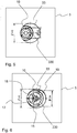
- FIGS. 5 and 6 Based on FIGS. 5 and 6 explains why with a tool bit 1 according to the invention in relation to the cross-sectional area particularly deep depressions in brittle-hard materials, such as glass or glass ceramic in particular with very smooth walls can be inserted.
- Fig. 5 shows a plan view of a recess 33 in a brittle-hard material 5 during the processing of the recess with a tool crown 1.
- Tool crown shown here is a conventional tool with a crown in the shape of a wreath.
- the diameter of the tool crown is 1 22 millimeters.
- the diameter can not be chosen larger, since otherwise 33 remains in the middle of the recess 33 material. This can be sufficient length
- the diameter of the tool crown must always be significantly smaller than the diameter or, in general, the cross-sectional dimension of the recess. However, this leads to large depth of the depression but quickly to instabilities of the tool, so that no smooth walls can be produced more.
- Fig. 6 shows for comparison a tool crown according to the invention 1 when introducing a recess 33 of the same dimensions.
- the tool crown 1 has the example in Fig. 3 shown by three rotationally symmetrical webs 17, 18, 19.
- the center 330 of the recess 33 is also processed when the outer rim, or the end face 12 of the hollow cylindrical abrasive body constantly outside the middle 330 runs. It can therefore be used in relation to the cross-sectional area of the recess 33 larger diameter of the grinding wheel 10.
- the grinding wheel 10 has a diameter of 34 millimeters.
- a larger grinding wheel 10 are used, which greatly improves the smoothness of the tool crown 1. The deeper a depression is inserted, the more critical the smooth running.
- the minimum diameter of a recess 33 of course depends on the diameter of the tool crown 1. Without limiting to the embodiments shown in the figures, an abrasive article 10 whose diameter is at least 5 millimeters is preferred. Particularly suitable are diameters of the grinding wheel 10 between 5 and 60 millimeters.
- Another suitable low-expansion material is titanium-doped quartz glass.
- Such a glass is available, for example, under the name ULE® from Corning Incorporated.
- a glass or glass ceramic material with low thermal expansion is understood in particular as meaning a material whose mean thermal expansion coefficient, for example given for the temperature interval from 0 to 50 ° C. ("coefficient of thermal expansion" CTE (0; 50)), is at most 0 ⁇ 100 ppb / K, preferably at most 0 ⁇ 50 ppb / K, more preferably at most - 0 ⁇ 20 ppb / K, particularly preferably at most 0 ⁇ 10 ppb / K.
- Fig. 7 shows a schematic cross section through such by machining by means of a tool crown 1 according to the invention producible glass or glass ceramic element 30.
- the glass or glass ceramic element 30 has at least a ground recess 33.
- several, in particular three recesses 33 are inserted, which are parallel to each other.
- the recesses 33 also extend in a straight line from the opening 36 on the surface 31 of the glass or glass ceramic element 30 to the bottom 331 of the respective recess 33.
- the recesses 33 have a ratio of depth or length of the recess 33 to minimum radius of more than 10: 1.
- a ratio of the depth of the recess 33 ie the length measured from opening 36 to the bottom 331, to the diameter of at least 10: 1.
- this ratio is approximately 15: 1, readable on the basis of the length and height of the recesses 33.
- a recess with a depth of 320 millimeters was produced in a glass ceramic with a diameter of the tool crown of 34 millimeters.
- the ratio of depth to minimum radius of the cross-sectional area is 18.8: 1.
- the depth to diameter ratio is 9.4: 1.
- Such depressions can be easily produced with the tool bit 1 according to the invention.
- the tool crown 1 is characterized by a high level of smoothness, which in turn leads to very smooth walls.
- the average roughness of the side wall 332 of the recess 33 has a value R a ⁇ 6 ⁇ m. If steps are present in the depression, for example during stepwise advancement of the tool crown and milling out of a height region in the glass or glass ceramic material, the above-mentioned value applies to surface regions outside the steps. Even average roughnesses of 0.1 ⁇ m to 5 ⁇ m can be achieved. Typical values are in the range of 0.5 to 3.5 ⁇ m. The roughness is therefore preferably not more than 5 ⁇ m, particularly preferably not more than 3.5 ⁇ m.
- the smoothest walls can be produced by drilling recesses 33.
- the tool crown 1 is inserted only with axial feed in the glass or glass ceramic material.
- the central grinding surface 15 allows drilling at all in a satisfactory time, because the peripheral speed of the abrasive 25 at the location of the cylinder axis is equal to zero.
- the minimum distance of the wall 332 of a recess 33 to a surface of the glass or glass ceramic element 30 may be at most 15 millimeters, preferably at most 10 millimeters.
- This distance can For example, be the distance to an outer surface of the glass or glass ceramic element 30, so for example, the distance of the wall 332 of in Fig. 7 Deepest recess 33 shown to the side surface 333 of the glass or glass ceramic element 30th
- Thin walls can also, as also exemplary and schematically in Fig. 7 shown to be made between two adjacent recesses 33.
- a plurality of mutually adjacent ground recesses 33 are present, wherein the minimum distance between the walls 332 of two adjacent recesses is at most 15 millimeters, preferably at most 10 millimeters.
- a wall thickness of only 5 millimeters could be verified in a Zerodur glass ceramic block.
- the recess 33 preferably, as in the illustrated example, a level bottom surface 331.
- Fig. 8 shows an exemplary embodiment of a typical cross-sectional shape of a recess 33.
- the cross section has the shape of a square or rectangle with rounded corners.
- the wall 332 of the recess 33 has short straight wall sections 335, which are interconnected by circularly curved wall sections 336.
- a recess 33 having a radius of the curved wall sections 336 of 19 millimeters and straight wall sections of a width of 5 millimeters was produced. This cross-sectional shape corresponds to that in Fig. 8 Shape.
- a ratio of depth to minimum radius of 320/19 16.8.
- Fig. 9 shows a photograph of a glass or glass ceramic element 30.
- this is a block of Zerodur glass ceramic.
- a recess 33 is inserted.
- the side surface 333 in the region of the depression 33 is coated with oil.
- the oiled area of the surface is now clearly translucent.
- the recess 33 has a cross-sectional shape corresponding to that in FIG Fig. 8 shown embodiment.
- two side channels 38 are inserted. These side channels 38 were inserted with the tool crown according to the invention, in particular not by milling, but by drilling.
- the invention finds application to produce light stable supports, in particular of glass or glass ceramic.
- Such carriers can be used in semiconductor fabrication in the exposure of semiconductor wafers or as mirror supports for telescopes.
Landscapes
- Engineering & Computer Science (AREA)
- Mechanical Engineering (AREA)
- Mining & Mineral Resources (AREA)
- Physics & Mathematics (AREA)
- General Physics & Mathematics (AREA)
- Optics & Photonics (AREA)
- Processing Of Stones Or Stones Resemblance Materials (AREA)
- Polishing Bodies And Polishing Tools (AREA)
- Constituent Portions Of Griding Lathes, Driving, Sensing And Control (AREA)
- Re-Forming, After-Treatment, Cutting And Transporting Of Glass Products (AREA)
- Mounting And Adjusting Of Optical Elements (AREA)
Applications Claiming Priority (1)
| Application Number | Priority Date | Filing Date | Title |
|---|---|---|---|
| DE102013106612.7A DE102013106612A1 (de) | 2013-06-25 | 2013-06-25 | Werkzeugkrone und mit der Werkzeugkrone herstellbares Glaskeramik-Erzeugnis |
Publications (2)
| Publication Number | Publication Date |
|---|---|
| EP2818288A1 EP2818288A1 (de) | 2014-12-31 |
| EP2818288B1 true EP2818288B1 (de) | 2019-05-15 |
Family
ID=51205160
Family Applications (1)
| Application Number | Title | Priority Date | Filing Date |
|---|---|---|---|
| EP14173806.2A Active EP2818288B1 (de) | 2013-06-25 | 2014-06-25 | Werkzeugkrone, Verfahren zur Herstellung eines Glas- oder Glaskeramikelements und Spiegelträger aus Glas- oder Glaskeramik für ein Teleskop |
Country Status (6)
| Country | Link |
|---|---|
| US (1) | US10926431B2 (https=) |
| EP (1) | EP2818288B1 (https=) |
| JP (2) | JP6469974B2 (https=) |
| CN (1) | CN104249310B (https=) |
| DE (1) | DE102013106612A1 (https=) |
| RU (1) | RU2661683C2 (https=) |
Families Citing this family (4)
| Publication number | Priority date | Publication date | Assignee | Title |
|---|---|---|---|---|
| CN104690615A (zh) * | 2015-03-20 | 2015-06-10 | 肖衍盛 | 对蓝宝石玻璃进行钻孔的加工方法 |
| CN106735365A (zh) * | 2017-01-11 | 2017-05-31 | 江苏正阳雕塑艺术传播有限公司 | 钎焊金刚石刀具 |
| WO2020196104A1 (ja) * | 2019-03-28 | 2020-10-01 | 住友電気工業株式会社 | 切削工具および光ファイバ母材製造方法 |
| CN112428098B (zh) * | 2019-08-26 | 2023-09-15 | 3M创新有限公司 | 研磨工具、包括该研磨工具的组件和抛光基板的方法 |
Citations (4)
| Publication number | Priority date | Publication date | Assignee | Title |
|---|---|---|---|---|
| EP0350526A1 (en) * | 1988-07-14 | 1990-01-17 | Asahi Diamond Industrial Co. Ltd. | Non-core drill |
| JP2005199619A (ja) * | 2004-01-16 | 2005-07-28 | Kyokuei Kenma Co Ltd | 段付穴形成用ドリル |
| US20090197040A1 (en) * | 2006-10-13 | 2009-08-06 | Asahi Glass Company, Limited | Method of boring glass substrate and glass substrate for plasma display manufactured by the method |
| US20100182711A1 (en) * | 2009-01-19 | 2010-07-22 | Schott Ag. | Substrate for a mirror support made of glass or glass ceramic |
Family Cites Families (61)
| Publication number | Priority date | Publication date | Assignee | Title |
|---|---|---|---|---|
| DE1890177U (de) | 1963-10-14 | 1964-03-26 | Ostia Fabrik Fuer Chemische Pr | Fadernde faltschachtelpackung. |
| US3514275A (en) | 1965-10-18 | 1970-05-26 | Owens Illinois Inc | Lightweight telescope mirror blank product and process of producing the same from glass |
| US3343308A (en) * | 1965-12-30 | 1967-09-26 | Fessel Paul | Cutting and grinding devices |
| DE1299131B (de) | 1966-08-20 | 1969-07-10 | Zeiss Carl Fa | Optischer Spiegel, insbesondere fuer astronomische Geraete, in Leichtbauweise |
| US3490405A (en) | 1967-08-23 | 1970-01-20 | Nasa | Method and apparatus for making curved reflectors |
| US3600257A (en) | 1969-01-09 | 1971-08-17 | Westinghouse Electric Corp | Lightweight mirror structures |
| US3613222A (en) | 1969-06-23 | 1971-10-19 | Owens Illinois Inc | Method for making a lightweight optical mirror |
| DE1952584B1 (de) | 1969-10-18 | 1970-08-06 | Heraeus Schott Quarzschmelze | Optischer Spiegel aus siliziumdioxidhaltigem Material in Leichtbauweise |
| SE383784B (sv) | 1970-01-28 | 1976-03-29 | France Etat Armement | Forfarande for framstellning av en optisk del med liten vikt av ett monolitiskt emne |
| US3754812A (en) | 1971-03-04 | 1973-08-28 | Heraeus Schott Quarzschmelze | Lightweight optical elements with honeycomb support plate |
| SU437621A1 (ru) * | 1972-06-21 | 1974-07-30 | Предприятие П/Я В-2438 | Алмазное кольцевое сверло |
| JPS5416226B2 (https=) | 1973-05-12 | 1979-06-20 | ||
| US3912380A (en) | 1973-06-25 | 1975-10-14 | Boeing Co | Composite type structure for large reflective mirrors |
| DE2828644A1 (de) | 1978-06-27 | 1980-01-10 | Johannes Breiting | Hartmetallbestueckter spiralbohrer |
| DE2929714C3 (de) | 1979-07-21 | 1982-02-04 | Heraeus Quarzschmelze Gmbh, 6450 Hanau | Verfahren zur Herstellung eines Leichtgewichtspiegels |
| JPS5838083B2 (ja) | 1980-01-22 | 1983-08-20 | 株式会社日本自動車部品総合研究所 | ハニカム構造体押出成形用ダイス装置 |
| DE3018785C2 (de) | 1980-05-16 | 1982-04-15 | Heraeus Quarzschmelze Gmbh, 6450 Hanau | Leichtgewichtsspiegel, insbesondere für astronomische Zwecke und Verfahren zu seiner Herstellung |
| US4383785A (en) * | 1980-07-30 | 1983-05-17 | The United States Of America As Represented By The Administrator Of The National Aeronautics And Space Administration | Method for milling and drilling glass |
| SU1073107A1 (ru) * | 1982-02-19 | 1984-02-15 | Предприятие П/Я Р-6793 | Способ сверлени плоских заготовок из неметаллических материалов и устройство дл его осуществлени |
| DE3534426A1 (de) | 1985-02-06 | 1986-08-07 | Benteler-Werke Ag Werk Neuhaus, 4790 Paderborn | Bohrvorrichtung zum bohren von bruchempfindlichen platten |
| US4799949A (en) | 1985-08-15 | 1989-01-24 | Corning Glass Works | Method of making low loss fiber optic coupler |
| US4911743A (en) * | 1986-05-29 | 1990-03-27 | Hughes Aircraft Company | Glass structure strengthening by etching |
| FR2609179B1 (fr) | 1986-12-30 | 1989-08-18 | Sfim | Procede pour realiser une face reflechissante sur une structure alveolaire afin d'obtenir un miroir ultra-leger |
| US4902216A (en) | 1987-09-08 | 1990-02-20 | Corning Incorporated | Extrusion die for protrusion and/or high cell density ceramic honeycomb structures |
| US4917934A (en) | 1989-04-27 | 1990-04-17 | Corning Incorporated | Telescope mirror blank and method of production |
| EP0486615A4 (en) | 1989-08-15 | 1992-08-05 | Foster-Miller Inc. | Film-based composite structures for ultralightweight sdi systems |
| US5137098A (en) * | 1990-02-14 | 1992-08-11 | Inland Diamond Products Company | Diamond tool for drilling and routing |
| US5076700A (en) * | 1990-12-20 | 1991-12-31 | Litton Systems, Inc. | Bonded lightweight mirror structure |
| WO1992012837A1 (de) * | 1991-01-15 | 1992-08-06 | Tyrolit Schleifmittelwerke Swarovski K.G. | Hohlbohrer |
| US5252009A (en) * | 1991-01-22 | 1993-10-12 | Joseph Bossler | Industrial and roadway identification and floor surface treatment system, and diamond surface drill bit for use in installing the system |
| JP3031571B2 (ja) | 1991-06-25 | 2000-04-10 | 触媒化成工業株式会社 | ハードコート膜およびハードコート膜付基材 |
| JP3257602B2 (ja) | 1992-03-04 | 2002-02-18 | ラサ工業株式会社 | ノンコアドリル |
| US5565052A (en) | 1992-03-05 | 1996-10-15 | Industrieanlagen-Betriebsgesellschaft Gmbh | Method for the production of a reflector |
| EP0630864A3 (en) * | 1993-05-24 | 1995-05-24 | Sumitomo Electric Industries | Process for producing a polarization-maintaining optical fiber. |
| JP2910022B2 (ja) | 1993-08-31 | 1999-06-23 | 信越石英株式会社 | 円輪型軽量反射鏡 |
| JP2884555B2 (ja) | 1993-09-30 | 1999-04-19 | 信越石英株式会社 | 軽量反射鏡 |
| DE29519102U1 (de) | 1995-12-04 | 1996-01-25 | Bornemann-Werkzeugtechnik GmbH, 31073 Delligsen | Rotierendes Werkzeug |
| US5823720A (en) * | 1996-02-16 | 1998-10-20 | Bitmoore | High precision cutting tools |
| DE19626364C2 (de) | 1996-07-01 | 1999-09-16 | Ocli Optical Coating Lab Gmbh | Oberflächenspiegeleinrichtung |
| DE19840004A1 (de) | 1998-09-02 | 2000-03-09 | Mekra Lang Gmbh & Co Kg | Außenspiegel für Kraftfahrzeuge |
| ES2161171B1 (es) | 1998-11-10 | 2003-04-01 | Bwx Technologies Inc | Un dispositivo optico reflector para lata temperatura. |
| JP2002079471A (ja) * | 2000-09-08 | 2002-03-19 | Toshiba Ceramics Co Ltd | 硬脆材料用穴あけ工具 |
| JP3926560B2 (ja) | 2000-12-15 | 2007-06-06 | 三菱電機株式会社 | 軽量化ミラー |
| JP4975911B2 (ja) * | 2001-07-02 | 2012-07-11 | 古河電気工業株式会社 | 光ファイバ母材の製造方法 |
| DE60233798D1 (de) | 2001-07-13 | 2009-11-05 | Ngk Insulators Ltd | Wabenstrukturkörper, wabenfilter und verfahren zur herstellung des strukturkörpers und des filters |
| US6890616B2 (en) | 2001-12-03 | 2005-05-10 | Hitachi Metals Ltd. | Ceramic honeycomb filter and its structure |
| JP3842122B2 (ja) | 2001-12-14 | 2006-11-08 | 三菱電機株式会社 | 軽量化ミラー |
| JP2004163803A (ja) | 2002-11-15 | 2004-06-10 | Mitsubishi Electric Corp | 軽量化ミラー |
| TWI238106B (en) * | 2002-12-20 | 2005-08-21 | Miyanaga Kk | Blade edge structure for core drill |
| JP4068496B2 (ja) | 2003-04-14 | 2008-03-26 | Nec東芝スペースシステム株式会社 | 鏡面母材及びそれを用いた鏡体及び、鏡体を用いた光学装置 |
| US6886951B2 (en) | 2003-09-04 | 2005-05-03 | Bennett Optical Research, Inc. | Active/adaptive actuator design of an adaptive optic mirror |
| JP4460325B2 (ja) | 2004-02-20 | 2010-05-12 | 太平洋セメント株式会社 | 天体望遠鏡用ミラー |
| CN101031521A (zh) | 2004-09-27 | 2007-09-05 | 肖特股份公司 | 由零膨胀材料制成的复合结构体和用于制造该结构体的方法 |
| DE102006006445A1 (de) | 2006-02-10 | 2007-08-23 | Maschinenfabrik Otto Baier Gmbh | Werkzeug zum Bohren, Kombination aus einem solchen Werkzeug und einem Werkzeughalter und zugehörige Bohrvorrichtung |
| FR2904433B1 (fr) | 2006-07-25 | 2008-11-28 | Alcatel Sa | Dispositif de fixation d'un miroir vitroceramique ou ceramique sur une structure embarquee a bord d'un engin spatial fonctionnant a temperature cryogenique |
| WO2008126306A1 (ja) | 2007-03-30 | 2008-10-23 | Ibiden Co., Ltd. | 触媒担持体 |
| DE102008039042B4 (de) | 2008-08-21 | 2011-04-14 | Schott Ag | Substrat für einen Spiegelträger mit reduziertem Gewicht sowie Spiegel mit gewichtsreduziertem Spiegelträger |
| WO2010061933A1 (ja) * | 2008-11-27 | 2010-06-03 | ジーエヌツール株式会社 | エンドミル |
| CN101774139B (zh) * | 2009-12-25 | 2012-02-15 | 田欣利 | 用于陶瓷外圆加工的环状车削刀具及其轴向加工方法 |
| DE102011008953B4 (de) | 2011-01-19 | 2020-08-20 | Schott Ag | Substrat mit Leichtgewichtsstruktur |
| DE102011000844B4 (de) | 2011-02-21 | 2022-11-17 | Wolfcraft Gmbh | Diamantlochsäge mit Zentrierbohrer und Anschlag |
-
2013
- 2013-06-25 DE DE102013106612.7A patent/DE102013106612A1/de active Pending
-
2014
- 2014-06-24 RU RU2014125542A patent/RU2661683C2/ru active
- 2014-06-25 JP JP2014130262A patent/JP6469974B2/ja active Active
- 2014-06-25 CN CN201410290908.0A patent/CN104249310B/zh active Active
- 2014-06-25 US US14/314,428 patent/US10926431B2/en active Active
- 2014-06-25 EP EP14173806.2A patent/EP2818288B1/de active Active
-
2018
- 2018-11-08 JP JP2018210622A patent/JP6770047B2/ja active Active
Patent Citations (4)
| Publication number | Priority date | Publication date | Assignee | Title |
|---|---|---|---|---|
| EP0350526A1 (en) * | 1988-07-14 | 1990-01-17 | Asahi Diamond Industrial Co. Ltd. | Non-core drill |
| JP2005199619A (ja) * | 2004-01-16 | 2005-07-28 | Kyokuei Kenma Co Ltd | 段付穴形成用ドリル |
| US20090197040A1 (en) * | 2006-10-13 | 2009-08-06 | Asahi Glass Company, Limited | Method of boring glass substrate and glass substrate for plasma display manufactured by the method |
| US20100182711A1 (en) * | 2009-01-19 | 2010-07-22 | Schott Ag. | Substrate for a mirror support made of glass or glass ceramic |
Also Published As
| Publication number | Publication date |
|---|---|
| CN104249310B (zh) | 2018-02-13 |
| JP6770047B2 (ja) | 2020-10-14 |
| RU2661683C2 (ru) | 2018-07-19 |
| CN104249310A (zh) | 2014-12-31 |
| JP2019030962A (ja) | 2019-02-28 |
| DE102013106612A1 (de) | 2015-01-08 |
| JP2015006725A (ja) | 2015-01-15 |
| US20140377505A1 (en) | 2014-12-25 |
| JP6469974B2 (ja) | 2019-02-13 |
| US10926431B2 (en) | 2021-02-23 |
| EP2818288A1 (de) | 2014-12-31 |
| RU2014125542A (ru) | 2015-12-27 |
Similar Documents
| Publication | Publication Date | Title |
|---|---|---|
| EP2212053B1 (de) | Verfahren zum herstellen von schneidrädchen | |
| EP2203393B1 (de) | Schneidrädchen, schneidmaschine mit dem Schneidrädchen und dazu gehörendem Verfahren. | |
| EP2818288B1 (de) | Werkzeugkrone, Verfahren zur Herstellung eines Glas- oder Glaskeramikelements und Spiegelträger aus Glas- oder Glaskeramik für ein Teleskop | |
| EP2635394B1 (de) | Einlippenbohrer | |
| DE102009049087C5 (de) | Bohrer | |
| EP2349623A2 (de) | Mehrschneidiges spanabhebendes bohrungs-nachbearbeitungswerkzeug | |
| EP1764176B1 (de) | Fräswerkzeug | |
| DE102016216926B4 (de) | Schneidelement, Werkzeug und Verfahren zum Erzeugen einer wendelförmig verlaufenden, trapezförmig hinterschnittenen Rille in einer zylindrischen Oberfläche einer Bohrung | |
| EP3837076B1 (de) | Faswerkzeug | |
| DE102012207455A1 (de) | Werkzeug und Verfahren zum mechanischen Aufrauen | |
| EP3507043A1 (de) | Aufrauwerkzeug und verfahren zum aufrauen einer zylindrischen oberfläche | |
| EP3634670B1 (de) | Fräsverfahren und verwendung eines schneideinsatzes | |
| DE4402843C2 (de) | Innenräumwerkzeug | |
| EP2679324A2 (de) | Werkzeuge und Verfahren zum mechanischen Aufrauen | |
| EP3681669B1 (de) | Aufrauwerkzeug und verfahren zu dessen herstellung | |
| EP3090825B1 (de) | Diamantsägeblatt zum ausbilden einer oberflächenstruktur auf einer fahrbahnoberfläche | |
| DE102017106372A1 (de) | Verfahren zur Bearbeitung eines Werkstückes und ein dadurch hergestelltes Werkstück | |
| EP1857238B1 (de) | Sägezahn mit Hartschicht | |
| DE10112165B4 (de) | Stabmesserkopf zum Verzahnen | |
| EP0912283B1 (de) | Hochgeschwindigkeitsfräsen | |
| DE102018101817A1 (de) | Mechanische aufrauungsprofilmodifizierung | |
| DE102006007787A1 (de) | Vorrichtung und Verfahren zum spanabhebenden Herstellen einer kalottenförmigen Ausnehmung in einem Werkstück | |
| EP2226143B1 (de) | Fräskopf für eine Fräsmaschine zum Herstellen von Brillengläsern aus Kunststoff | |
| EP1124766B1 (de) | Quarzglasplatten hoher brechzahlhomogenität | |
| EP2147748B1 (de) | Wetzstab und Verfahren zu dessen Herstellung |
Legal Events
| Date | Code | Title | Description |
|---|---|---|---|
| PUAI | Public reference made under article 153(3) epc to a published international application that has entered the european phase |
Free format text: ORIGINAL CODE: 0009012 |
|
| 17P | Request for examination filed |
Effective date: 20140625 |
|
| AK | Designated contracting states |
Kind code of ref document: A1 Designated state(s): AL AT BE BG CH CY CZ DE DK EE ES FI FR GB GR HR HU IE IS IT LI LT LU LV MC MK MT NL NO PL PT RO RS SE SI SK SM TR |
|
| AX | Request for extension of the european patent |
Extension state: BA ME |
|
| RBV | Designated contracting states (corrected) |
Designated state(s): AL AT BE BG CH CY CZ DE DK EE ES FI FR GB GR HR HU IE IS IT LI LT LU LV MC MK MT NL NO PL PT RO RS SE SI SK SM TR |
|
| STAA | Information on the status of an ep patent application or granted ep patent |
Free format text: STATUS: EXAMINATION IS IN PROGRESS |
|
| 17Q | First examination report despatched |
Effective date: 20170224 |
|
| GRAP | Despatch of communication of intention to grant a patent |
Free format text: ORIGINAL CODE: EPIDOSNIGR1 |
|
| STAA | Information on the status of an ep patent application or granted ep patent |
Free format text: STATUS: GRANT OF PATENT IS INTENDED |
|
| INTG | Intention to grant announced |
Effective date: 20181115 |
|
| GRAS | Grant fee paid |
Free format text: ORIGINAL CODE: EPIDOSNIGR3 |
|
| GRAA | (expected) grant |
Free format text: ORIGINAL CODE: 0009210 |
|
| STAA | Information on the status of an ep patent application or granted ep patent |
Free format text: STATUS: THE PATENT HAS BEEN GRANTED |
|
| AK | Designated contracting states |
Kind code of ref document: B1 Designated state(s): AL AT BE BG CH CY CZ DE DK EE ES FI FR GB GR HR HU IE IS IT LI LT LU LV MC MK MT NL NO PL PT RO RS SE SI SK SM TR |
|
| REG | Reference to a national code |
Ref country code: CH Ref legal event code: EP Ref country code: GB Ref legal event code: FG4D Free format text: NOT ENGLISH |
|
| REG | Reference to a national code |
Ref country code: DE Ref legal event code: R096 Ref document number: 502014011706 Country of ref document: DE |
|
| REG | Reference to a national code |
Ref country code: IE Ref legal event code: FG4D Free format text: LANGUAGE OF EP DOCUMENT: GERMAN |
|
| REG | Reference to a national code |
Ref country code: NL Ref legal event code: FP |
|
| REG | Reference to a national code |
Ref country code: LT Ref legal event code: MG4D |
|
| PG25 | Lapsed in a contracting state [announced via postgrant information from national office to epo] |
Ref country code: NO Free format text: LAPSE BECAUSE OF FAILURE TO SUBMIT A TRANSLATION OF THE DESCRIPTION OR TO PAY THE FEE WITHIN THE PRESCRIBED TIME-LIMIT Effective date: 20190815 Ref country code: FI Free format text: LAPSE BECAUSE OF FAILURE TO SUBMIT A TRANSLATION OF THE DESCRIPTION OR TO PAY THE FEE WITHIN THE PRESCRIBED TIME-LIMIT Effective date: 20190515 Ref country code: LT Free format text: LAPSE BECAUSE OF FAILURE TO SUBMIT A TRANSLATION OF THE DESCRIPTION OR TO PAY THE FEE WITHIN THE PRESCRIBED TIME-LIMIT Effective date: 20190515 Ref country code: ES Free format text: LAPSE BECAUSE OF FAILURE TO SUBMIT A TRANSLATION OF THE DESCRIPTION OR TO PAY THE FEE WITHIN THE PRESCRIBED TIME-LIMIT Effective date: 20190515 Ref country code: HR Free format text: LAPSE BECAUSE OF FAILURE TO SUBMIT A TRANSLATION OF THE DESCRIPTION OR TO PAY THE FEE WITHIN THE PRESCRIBED TIME-LIMIT Effective date: 20190515 Ref country code: AL Free format text: LAPSE BECAUSE OF FAILURE TO SUBMIT A TRANSLATION OF THE DESCRIPTION OR TO PAY THE FEE WITHIN THE PRESCRIBED TIME-LIMIT Effective date: 20190515 Ref country code: SE Free format text: LAPSE BECAUSE OF FAILURE TO SUBMIT A TRANSLATION OF THE DESCRIPTION OR TO PAY THE FEE WITHIN THE PRESCRIBED TIME-LIMIT Effective date: 20190515 Ref country code: PT Free format text: LAPSE BECAUSE OF FAILURE TO SUBMIT A TRANSLATION OF THE DESCRIPTION OR TO PAY THE FEE WITHIN THE PRESCRIBED TIME-LIMIT Effective date: 20190915 |
|
| PG25 | Lapsed in a contracting state [announced via postgrant information from national office to epo] |
Ref country code: LV Free format text: LAPSE BECAUSE OF FAILURE TO SUBMIT A TRANSLATION OF THE DESCRIPTION OR TO PAY THE FEE WITHIN THE PRESCRIBED TIME-LIMIT Effective date: 20190515 Ref country code: GR Free format text: LAPSE BECAUSE OF FAILURE TO SUBMIT A TRANSLATION OF THE DESCRIPTION OR TO PAY THE FEE WITHIN THE PRESCRIBED TIME-LIMIT Effective date: 20190816 Ref country code: RS Free format text: LAPSE BECAUSE OF FAILURE TO SUBMIT A TRANSLATION OF THE DESCRIPTION OR TO PAY THE FEE WITHIN THE PRESCRIBED TIME-LIMIT Effective date: 20190515 Ref country code: BG Free format text: LAPSE BECAUSE OF FAILURE TO SUBMIT A TRANSLATION OF THE DESCRIPTION OR TO PAY THE FEE WITHIN THE PRESCRIBED TIME-LIMIT Effective date: 20190815 |
|
| PG25 | Lapsed in a contracting state [announced via postgrant information from national office to epo] |
Ref country code: RO Free format text: LAPSE BECAUSE OF FAILURE TO SUBMIT A TRANSLATION OF THE DESCRIPTION OR TO PAY THE FEE WITHIN THE PRESCRIBED TIME-LIMIT Effective date: 20190515 Ref country code: CZ Free format text: LAPSE BECAUSE OF FAILURE TO SUBMIT A TRANSLATION OF THE DESCRIPTION OR TO PAY THE FEE WITHIN THE PRESCRIBED TIME-LIMIT Effective date: 20190515 Ref country code: SK Free format text: LAPSE BECAUSE OF FAILURE TO SUBMIT A TRANSLATION OF THE DESCRIPTION OR TO PAY THE FEE WITHIN THE PRESCRIBED TIME-LIMIT Effective date: 20190515 Ref country code: EE Free format text: LAPSE BECAUSE OF FAILURE TO SUBMIT A TRANSLATION OF THE DESCRIPTION OR TO PAY THE FEE WITHIN THE PRESCRIBED TIME-LIMIT Effective date: 20190515 Ref country code: DK Free format text: LAPSE BECAUSE OF FAILURE TO SUBMIT A TRANSLATION OF THE DESCRIPTION OR TO PAY THE FEE WITHIN THE PRESCRIBED TIME-LIMIT Effective date: 20190515 |
|
| REG | Reference to a national code |
Ref country code: CH Ref legal event code: PL |
|
| REG | Reference to a national code |
Ref country code: DE Ref legal event code: R097 Ref document number: 502014011706 Country of ref document: DE |
|
| PG25 | Lapsed in a contracting state [announced via postgrant information from national office to epo] |
Ref country code: SM Free format text: LAPSE BECAUSE OF FAILURE TO SUBMIT A TRANSLATION OF THE DESCRIPTION OR TO PAY THE FEE WITHIN THE PRESCRIBED TIME-LIMIT Effective date: 20190515 Ref country code: IT Free format text: LAPSE BECAUSE OF FAILURE TO SUBMIT A TRANSLATION OF THE DESCRIPTION OR TO PAY THE FEE WITHIN THE PRESCRIBED TIME-LIMIT Effective date: 20190515 Ref country code: MC Free format text: LAPSE BECAUSE OF FAILURE TO SUBMIT A TRANSLATION OF THE DESCRIPTION OR TO PAY THE FEE WITHIN THE PRESCRIBED TIME-LIMIT Effective date: 20190515 |
|
| PLBE | No opposition filed within time limit |
Free format text: ORIGINAL CODE: 0009261 |
|
| STAA | Information on the status of an ep patent application or granted ep patent |
Free format text: STATUS: NO OPPOSITION FILED WITHIN TIME LIMIT |
|
| PG25 | Lapsed in a contracting state [announced via postgrant information from national office to epo] |
Ref country code: TR Free format text: LAPSE BECAUSE OF FAILURE TO SUBMIT A TRANSLATION OF THE DESCRIPTION OR TO PAY THE FEE WITHIN THE PRESCRIBED TIME-LIMIT Effective date: 20190515 |
|
| 26N | No opposition filed |
Effective date: 20200218 |
|
| PG25 | Lapsed in a contracting state [announced via postgrant information from national office to epo] |
Ref country code: PL Free format text: LAPSE BECAUSE OF FAILURE TO SUBMIT A TRANSLATION OF THE DESCRIPTION OR TO PAY THE FEE WITHIN THE PRESCRIBED TIME-LIMIT Effective date: 20190515 Ref country code: IE Free format text: LAPSE BECAUSE OF NON-PAYMENT OF DUE FEES Effective date: 20190625 |
|
| PG25 | Lapsed in a contracting state [announced via postgrant information from national office to epo] |
Ref country code: LU Free format text: LAPSE BECAUSE OF NON-PAYMENT OF DUE FEES Effective date: 20190625 Ref country code: LI Free format text: LAPSE BECAUSE OF NON-PAYMENT OF DUE FEES Effective date: 20190630 Ref country code: CH Free format text: LAPSE BECAUSE OF NON-PAYMENT OF DUE FEES Effective date: 20190630 Ref country code: SI Free format text: LAPSE BECAUSE OF FAILURE TO SUBMIT A TRANSLATION OF THE DESCRIPTION OR TO PAY THE FEE WITHIN THE PRESCRIBED TIME-LIMIT Effective date: 20190515 |
|
| REG | Reference to a national code |
Ref country code: AT Ref legal event code: MM01 Ref document number: 1132904 Country of ref document: AT Kind code of ref document: T Effective date: 20190625 |
|
| PG25 | Lapsed in a contracting state [announced via postgrant information from national office to epo] |
Ref country code: AT Free format text: LAPSE BECAUSE OF NON-PAYMENT OF DUE FEES Effective date: 20190625 |
|
| PG25 | Lapsed in a contracting state [announced via postgrant information from national office to epo] |
Ref country code: CY Free format text: LAPSE BECAUSE OF FAILURE TO SUBMIT A TRANSLATION OF THE DESCRIPTION OR TO PAY THE FEE WITHIN THE PRESCRIBED TIME-LIMIT Effective date: 20190515 |
|
| PG25 | Lapsed in a contracting state [announced via postgrant information from national office to epo] |
Ref country code: IS Free format text: LAPSE BECAUSE OF FAILURE TO SUBMIT A TRANSLATION OF THE DESCRIPTION OR TO PAY THE FEE WITHIN THE PRESCRIBED TIME-LIMIT Effective date: 20190915 |
|
| PG25 | Lapsed in a contracting state [announced via postgrant information from national office to epo] |
Ref country code: HU Free format text: LAPSE BECAUSE OF FAILURE TO SUBMIT A TRANSLATION OF THE DESCRIPTION OR TO PAY THE FEE WITHIN THE PRESCRIBED TIME-LIMIT; INVALID AB INITIO Effective date: 20140625 Ref country code: MT Free format text: LAPSE BECAUSE OF FAILURE TO SUBMIT A TRANSLATION OF THE DESCRIPTION OR TO PAY THE FEE WITHIN THE PRESCRIBED TIME-LIMIT Effective date: 20190515 |
|
| PG25 | Lapsed in a contracting state [announced via postgrant information from national office to epo] |
Ref country code: MK Free format text: LAPSE BECAUSE OF FAILURE TO SUBMIT A TRANSLATION OF THE DESCRIPTION OR TO PAY THE FEE WITHIN THE PRESCRIBED TIME-LIMIT Effective date: 20190515 |
|
| P01 | Opt-out of the competence of the unified patent court (upc) registered |
Effective date: 20230516 |
|
| PGFP | Annual fee paid to national office [announced via postgrant information from national office to epo] |
Ref country code: DE Payment date: 20250618 Year of fee payment: 12 |
|
| PGFP | Annual fee paid to national office [announced via postgrant information from national office to epo] |
Ref country code: GB Payment date: 20250618 Year of fee payment: 12 |
|
| PGFP | Annual fee paid to national office [announced via postgrant information from national office to epo] |
Ref country code: NL Payment date: 20250618 Year of fee payment: 12 Ref country code: BE Payment date: 20250618 Year of fee payment: 12 |
|
| PGFP | Annual fee paid to national office [announced via postgrant information from national office to epo] |
Ref country code: FR Payment date: 20250624 Year of fee payment: 12 |