WO2020196104A1 - 切削工具および光ファイバ母材製造方法 - Google Patents
切削工具および光ファイバ母材製造方法 Download PDFInfo
- Publication number
- WO2020196104A1 WO2020196104A1 PCT/JP2020/011788 JP2020011788W WO2020196104A1 WO 2020196104 A1 WO2020196104 A1 WO 2020196104A1 JP 2020011788 W JP2020011788 W JP 2020011788W WO 2020196104 A1 WO2020196104 A1 WO 2020196104A1
- Authority
- WO
- WIPO (PCT)
- Prior art keywords
- region
- cutting tool
- hole
- optical fiber
- core
- Prior art date
Links
Images


Classifications
-
- B—PERFORMING OPERATIONS; TRANSPORTING
- B24—GRINDING; POLISHING
- B24B—MACHINES, DEVICES, OR PROCESSES FOR GRINDING OR POLISHING; DRESSING OR CONDITIONING OF ABRADING SURFACES; FEEDING OF GRINDING, POLISHING, OR LAPPING AGENTS
- B24B7/00—Machines or devices designed for grinding plane surfaces on work, including polishing plane glass surfaces; Accessories therefor
- B24B7/20—Machines or devices designed for grinding plane surfaces on work, including polishing plane glass surfaces; Accessories therefor characterised by a special design with respect to properties of the material of non-metallic articles to be ground
- B24B7/22—Machines or devices designed for grinding plane surfaces on work, including polishing plane glass surfaces; Accessories therefor characterised by a special design with respect to properties of the material of non-metallic articles to be ground for grinding inorganic material, e.g. stone, ceramics, porcelain
-
- B—PERFORMING OPERATIONS; TRANSPORTING
- B24—GRINDING; POLISHING
- B24B—MACHINES, DEVICES, OR PROCESSES FOR GRINDING OR POLISHING; DRESSING OR CONDITIONING OF ABRADING SURFACES; FEEDING OF GRINDING, POLISHING, OR LAPPING AGENTS
- B24B5/00—Machines or devices designed for grinding surfaces of revolution on work, including those which also grind adjacent plane surfaces; Accessories therefor
- B24B5/36—Single-purpose machines or devices
- B24B5/40—Single-purpose machines or devices for grinding tubes internally
-
- B—PERFORMING OPERATIONS; TRANSPORTING
- B24—GRINDING; POLISHING
- B24D—TOOLS FOR GRINDING, BUFFING OR SHARPENING
- B24D3/00—Physical features of abrasive bodies, or sheets, e.g. abrasive surfaces of special nature; Abrasive bodies or sheets characterised by their constituents
-
- B—PERFORMING OPERATIONS; TRANSPORTING
- B24—GRINDING; POLISHING
- B24D—TOOLS FOR GRINDING, BUFFING OR SHARPENING
- B24D5/00—Bonded abrasive wheels, or wheels with inserted abrasive blocks, designed for acting only by their periphery; Bushings or mountings therefor
- B24D5/14—Zonally-graded wheels; Composite wheels comprising different abrasives
-
- B—PERFORMING OPERATIONS; TRANSPORTING
- B24—GRINDING; POLISHING
- B24D—TOOLS FOR GRINDING, BUFFING OR SHARPENING
- B24D7/00—Bonded abrasive wheels, or wheels with inserted abrasive blocks, designed for acting otherwise than only by their periphery, e.g. by the front face; Bushings or mountings therefor
- B24D7/14—Zonally-graded wheels; Composite wheels comprising different abrasives
-
- C—CHEMISTRY; METALLURGY
- C03—GLASS; MINERAL OR SLAG WOOL
- C03B—MANUFACTURE, SHAPING, OR SUPPLEMENTARY PROCESSES
- C03B37/00—Manufacture or treatment of flakes, fibres, or filaments from softened glass, minerals, or slags
- C03B37/01—Manufacture of glass fibres or filaments
- C03B37/012—Manufacture of preforms for drawing fibres or filaments
-
- G—PHYSICS
- G02—OPTICS
- G02B—OPTICAL ELEMENTS, SYSTEMS OR APPARATUS
- G02B6/00—Light guides; Structural details of arrangements comprising light guides and other optical elements, e.g. couplings
- G02B6/02—Optical fibres with cladding with or without a coating
- G02B6/02042—Multicore optical fibres
Definitions
- the present disclosure relates to a cutting tool and a method for manufacturing an optical fiber base material.
- This application claims priority based on Japanese Application No. 2019-062449 filed on March 28, 2019, and incorporates all the contents described in the Japanese application.
- An optical fiber base material having a core extending in the longitudinal direction may be manufactured by the rod-in-collapsing method.
- a jacket material is produced by forming holes extending in the longitudinal direction in a cylindrical glass body. Next, after inserting the core rod into this hole, the core rod and the jacket material are integrated by heating from the outside of the jacket material to manufacture an optical fiber base material.
- Patent Document 1 discloses a technique for manufacturing an optical fiber base material having one core extending in the longitudinal direction (hereinafter, referred to as a single core optical fiber base material).
- Patent Document 2 discloses a technique for manufacturing an optical fiber base material having a plurality of cores (hereinafter, referred to as a multi-core optical fiber base material).
- the cutting tool is a cutting tool including a shank portion and a cutting portion provided at one end of the shank portion, and the cutting portion is provided at one end of the cutting tool. It has a first region and a second region located closer to the center of the cutting tool than the first region, and abrasive grains are fixed to the first region and the second region, and the second region is used.
- the average particle size of the abrasive grains in the first region is smaller than the average particle size of the abrasive grains in the first region.
- the optical fiber base material manufacturing method is a method for manufacturing an optical fiber base material having a core extending in the longitudinal direction, from one end to the other end in the axial direction of the glass body.
- a jacket material is produced by forming a hole using the cutting tool of the present disclosure, a core rod is inserted into the hole, and the jacket material is heated to integrate the jacket material and the core rod.
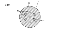
- FIG. 1 is a cross-sectional view showing an example of a multi-core optical fiber.
- FIG. 2A is a front view showing a glass body used in the optical fiber base material manufacturing method according to one aspect of the present disclosure.
- FIG. 2B is a cross-sectional view showing a glass body used in the optical fiber base material manufacturing method according to one aspect of the present disclosure.
- FIG. 3A is a side view showing an example of a cutting tool according to one aspect of the present disclosure.
- FIG. 3B is a front view showing an example of a cutting tool according to one aspect of the present disclosure.
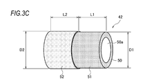
- FIG. 3C is an enlarged perspective view of the cutting portion of the cutting tools of FIGS. 3A and 3B to which the abrasive grains are fixed.
- FIG. 3A is a side view showing an example of a cutting tool according to one aspect of the present disclosure.
- FIG. 3B is a front view showing an example of a cutting tool according to one aspect of the present disclosure.
- FIG. 3C is
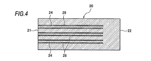
- FIG. 4 is a cross-sectional view including the central axis of the glass body in the step of producing the jacket material according to the embodiment of the present disclosure.
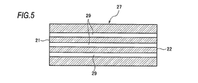
- FIG. 5 is a cross-sectional view including a central axis of the jacket material according to the embodiment of the present disclosure.
- FIG. 6 is a cross-sectional view including a central axis of the jacket material into which the core rod is inserted in the step of inserting the core rod according to the embodiment of the present disclosure.
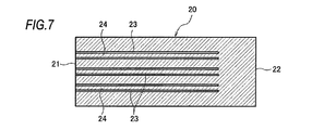
- FIG. 7 is a cross-sectional view including the central axis of the glass body in the step of producing the jacket material according to the modified example of the embodiment of the present disclosure.
- FIG. 8 is a cross-sectional view including a central axis of the jacket material according to a modified example of the embodiment of the present disclosure.
- FIG. 9 is a cross-sectional view including a central axis of the jacket material into which the core rod is inserted in the step of inserting the core rod according to the modified example of the embodiment of the present disclosure.
- FIG. 10 is a conceptual diagram showing an integration process according to the embodiment of the present disclosure.
- FIG. 11 is a cross-sectional view showing an example of the jacket material.
- FIG. 12A is a front view showing another example of the cutting tool.
- FIG. 12B is a front view showing still another example of the cutting tool.
- a hole is provided in the center of the jacket pipe.
- the jacket pipe is heated from the outside, the jacket pipe deforms while maintaining a symmetrical state with respect to the central axis of the jacket pipe. That is, the inner circumference of the hole shrinks uniformly toward the central axis of the hole, and the inner wall of the hole contacts the core rod. At the same time as the inner circumference of the hole is reduced, the inner wall of the hole becomes smooth.
- the multi-core optical fiber base material is manufactured by the rod-in-collapse method, if the clearance between the inner diameter of the hole and the outer diameter of the core rod is small, the position accuracy of the core will be high. However, if the clearance is small, the inner wall of the hole is likely to come into contact with the core rod before the roughness of the inner wall of the hole is sufficiently reduced, so that air bubbles are likely to remain.
- Some multi-core optical fiber base materials have holes other than the center of the jacket pipe.
- the vicinity of the outer circumference of the jacket pipe is heated more strongly than the center of the jacket pipe. Therefore, in one cross section of the jacket pipe, it is difficult to keep the roughness of the inner wall of the hole other than the center of the jacket pipe equal over the entire circumference of the inner wall.
- the inner wall of the hole can come into contact with the core rod before the roughness of the inner wall of the portion of the inner wall of the hole near the center of the jacket pipe becomes sufficiently small, so that air bubbles are generated. It becomes easy to remain.
- a cutting tool including a shank portion and a cutting portion provided at one end of the shank portion.
- the cutting portion includes a first region provided at one end of the cutting tool and the first portion. It has a second region located closer to the center of the cutting tool than the region, and abrasive grains are fixed to the first region and the second region, and the average particle size of the abrasive grains in the second region is , Smaller than the average particle size of the abrasive grains in the first region.
- the present disclosure ensures the productivity of drilling in the first region and the inner wall of the hole in the second region. Roughness can be reduced. Therefore, in the present disclosure, it is possible to obtain an optical fiber base material in which air bubbles are less likely to remain at the boundary between the inner wall of the hole and the core rod without impairing the productivity of drilling.
- the abrasive grains are diamond grains.
- the abrasive grains are diamond grains.
- holes having a smooth inner wall are easily formed in the glass body.
- the average particle size of the abrasive grains in the first region is 100 ⁇ m or more, and the average particle size of the abrasive grains in the second region is less than 100 ⁇ m. Since the average particle size of the abrasive grains in the first region is 100 ⁇ m or more, the present disclosure can maintain a high drilling speed. Further, since the average particle size of the abrasive grains in the second region is less than 100 ⁇ m, the present disclosure can obtain a smooth inner wall even at the above processing speed.
- the outer diameter of the second region is larger than the outer diameter of the first region. Since the outer diameter of the second region is larger than the outer diameter of the first region, the second region can reliably process the inner wall of the hole after the first region has processed the hole. Therefore, the present disclosure can surely obtain a hole having a smooth inner wall.
- the difference between the outer diameter of the second region and the outer diameter of the first region is in the range of 10 ⁇ m or more and 300 ⁇ m or less. Since the difference between the outer diameter of the second region and the outer diameter of the first region is 10 ⁇ m or more, even if the abrasive grains of the second region are worn, the processing of the inner wall of the hole can be continued in the second region. .. Further, since the difference between the outer diameter of the second region and the outer diameter of the first region is 300 ⁇ m or less, the load on the second region during machining does not increase, and the wear of the abrasive grains in the second region is reduced. ..
- the optical fiber base material manufacturing method is a method for manufacturing an optical fiber base material having a core extending in the longitudinal direction, and the method is in the axial direction of the glass body.
- a jacket material is produced by forming a hole from one end to the other end using the cutting tool of the present disclosure, a core rod is inserted into the hole, and the jacket material is heated to form the jacket material and the core rod.
- the present disclosure ensures the productivity of drilling in the first region and the holes in the second region. The roughness of the inner wall of the can be reduced.
- the present disclosure it is possible to obtain an optical fiber base material in which air bubbles are less likely to remain at the boundary between the inner wall of the hole and the core rod without impairing the productivity of drilling. According to the present disclosure, by drawing the optical fiber base material produced in this manner, it is possible to produce an optical fiber having less variation in the outer diameter of the optical fiber and no decrease in mechanical strength.
- An object of the present disclosure is to provide a method for manufacturing an optical fiber base material and a cutting tool in which air bubbles are less likely to remain at the boundary between the inner wall of a hole and a core rod without impairing the productivity of drilling.
- FIG. 1 is a cross-sectional view showing an example of a multi-core optical fiber 1.
- the multi-core optical fiber 1 has, for example, seven cores 11 in the clad 10.
- the core 11 extends in the longitudinal direction of the multi-core optical fiber 1.
- the core 11 includes a central core arranged on the optical fiber central axis and an outer peripheral core arranged on the hexagonal vertices around the optical fiber central axis.
- Each core 11 includes a region having a refractive index higher than that of the clad 10 and is configured to propagate light.
- the rod-in-collapsing method includes, for example, a step of producing a jacket material by forming holes from one end to the other end in the axial direction of a cylindrical glass body, and a step of inserting a core rod into the holes of the jacket material. It has a step of heating the jacket material to integrate the jacket material and the core rod.
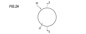
- FIG. 2A is a front view seen from one end 21 of the glass body 20 used in the optical fiber base material manufacturing method according to one aspect of the present disclosure.
- FIG. 2B is a cross-sectional view taken along the line XX of FIG. 2A.
- the glass body 20 is, for example, silica glass to which fluorine is added or pure silica glass, and has a cylindrical shape.
- the glass body 20 has seven holes extending from one end 21 to the other end 22 in the axial direction in a drill shape. Provided with a tool.
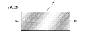
- FIG. 3A to 3C are diagrams illustrating a cutting tool 40 used in the optical fiber base material manufacturing method according to one aspect of the present disclosure.
- FIG. 3A is a side view showing an example of the cutting tool 40.
- FIG. 3B is a front view showing an example of the cutting tool 40.
- FIG. 3C is an enlarged perspective view of a cutting portion of the cutting tool 40 to which the abrasive grains are fixed.
- the cutting tool 40 includes a shank portion 41 and a cutting portion 42.
- the shank portion 41 is, for example, a hollow round bar made of metal, and is configured so that a rotational force around an axis extending in the longitudinal direction is applied to the shank portion 41.
- the cutting portion 42 is located in front of the shank portion 41 (one end of the cutting tool 40, which is the right side in FIG. 3A), and is configured to rotate together with the shank portion 41.
- the cutting portion 42 is, for example, a hollow round bar, and a discharge path 50a concentric with the shank portion 41 is provided at the center on the cross section of the cutting portion 42.
- the outer peripheral surface of the cutting portion 42 has a first region 51 provided at one end of the cutting tool 40 and a second region 52 located closer to the center of the cutting tool 40 than the first region 51.
- the second region 52 is located behind the first region 51 (on the left side in FIG. 3A).
- the front end of the second region 52 is connected to, for example, the rear end of the first region 51.
- the length L1 of the first region 51 and the length L2 of the second region 52 are both, for example, 5 mm.
- Abrasive grains (for example, diamond grains) are fixed to the first region 51 (including the tip surface 50) and the second region 52 by, for example, a multilayer electrodeposition structure.
- the average particle size of the abrasive grains is evaluated by the particle size specified in JIS_B_4130.
- the average particle size of the diamond grains in the first region 51 is 100 ⁇ m or more (# 140 or less in the particle size display in JIS_B_4130), preferably 150 ⁇ m or more (# 100 or less in the particle size display in JIS_B_4130).
- the average particle size of the diamond grains in the second region 52 is smaller than the average particle size of the diamond grains in the first region 51. Specifically, the average particle size of the diamond grains in the second region 52 is less than 100 ⁇ m, preferably 50 ⁇ m or less (# 270 or more in the particle size indication in JIS_B_4130).
- the average particle size is generally determined, for example, by a method of sorting particles by a plurality of types of sieves.
- the average particle size of 105 ⁇ m corresponds to the particle size display # 140
- the average particle size of 149 ⁇ m corresponds to # 100
- the average particle size of 53 ⁇ m corresponds to # 270.
- the present embodiment can maintain a high drilling speed.
- the present embodiment can further increase the processing speed of drilling.
- the average particle size of the diamond grains in the second region 52 is less than 100 ⁇ m, in the present embodiment, a smooth inner wall of holes can be obtained even at the above processing speed.
- the average particle size of the diamond grains in the second region 52 is 50 ⁇ m or less, the present embodiment can further smooth the inner wall of the hole.
- the amount of abrasive grains fixed to the cutting portion 42 is adjusted by dressing to form a cutting edge.
- the diamond may be a synthetic diamond or a natural diamond. Although diamond is suitable for processing glass, CBN (Cubic Boron Nitride: cubic boron nitride) may be used for the abrasive grains of the present disclosure.
- first region 51 and the second region 52 are connected.
- a region in which the abrasive grains do not adhere may be provided between the first region 51 and the second region 52, and the first region 51 and the second region 52 may be arranged apart from each other.
- the present embodiment is not limited to the two regions of the first region 51 and the second region 52, and three or more regions to which the abrasive grains are fixed may be provided. In this case, the average particle size of the abrasive grains in the region located at the rearmost position is the smallest.
- the outer diameter of the second region 52 and the outer diameter of the first region 51 may be the same size.
- the outer diameter D2 of the second region 52 is larger than the outer diameter D1 of the first region 51. This is because after the first region 51 provides the hole in the glass body 20, the second region can reliably process the inner wall of the hole. Thereby, in this embodiment, a hole having a smooth inner wall can be obtained.
- the difference (D2-D1) between the outer diameter D2 of the second region 52 and the outer diameter D1 of the first region 51 is in the range of 10 ⁇ m or more and 300 ⁇ m or less. Since the difference between the outer diameter D2 of the second region 52 and the outer diameter D1 of the first region 51 is 10 ⁇ m or more, even if the diamond grains of the second region 52 are worn by using the cutting tool 40 multiple times. , The second region 52 can continue to process the inner wall of the hole. In addition, since the difference between the outer diameter D2 of the second region 52 and the outer diameter D1 of the first region 51 is 300 ⁇ m or less, the load on the second region 52 during machining does not increase, and the load on the second region 52 does not increase. Diamond grain wear is reduced.
- the cutting tool 40 is rotationally driven, with the cutting portion 42 arranged in front at the head.
- the cutting tool 40 is inserted into the glass body 20 from one end 21 to the other end 22 of the glass body 20.
- the glass material cut by the cutting portion 42 is sent backward from, for example, the discharge path 50a and discharged.
- FIG. 4 to 6 are cross-sectional views including the central axis of the glass body 20 and the jacket material 27 in the method for manufacturing the optical fiber base material.
- a total of seven ring-shaped holes 28 are formed in the glass body 20 by the hollow round bar-shaped cutting tool 40.
- FIG. 4 shows an intermediate step in which three ring-shaped holes 28 on the cross section are formed out of a total of seven.
- An uncut rod 24 remains in the center of each ring-shaped hole 28.
- the through hole 29 corresponds to the hole of the present disclosure.
- the inner surface of the through hole 29 is cleaned with a fluorine-based gas or the like.
- FIG. 6 shows three core rods 26 on the cross section.
- the core rod 26 located at the center of the multi-core optical fiber 1 is arranged concentrically with the through hole 29 arranged on the central axis of the jacket material 27.
- the plurality of core rods 26 located on the outer peripheral core of the multi-core optical fiber 1 are arranged near the central axis of the jacket material 27 in the corresponding through holes 29.
- the hole of the present disclosure does not have to penetrate.
- a total of seven ring-shaped bottomed holes 23 are formed in the glass body 20.
- FIG. 7 shows three ring-shaped bottomed holes 23 on the cross section.
- the ring-shaped bottomed hole 23 corresponds to the hole of the present disclosure.
- the ring-shaped bottomed hole 23 extends along the longitudinal direction and reaches from the other end 22 to a position where a predetermined thickness is left.
- an uncut rod 24 surrounded by a ring-shaped bottomed hole 23 remains.
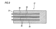
- FIG. 9 shows three core rods 26 on a cross section.
- the core rod 26 located at the center of the multi-core optical fiber 1 is arranged concentrically with the circular bottom hole 25 arranged on the central axis of the jacket material 27.
- the plurality of core rods 26 located in the outer peripheral core of the multi-core optical fiber 1 are arranged near the central axis of the jacket material 27 in the corresponding circular bottomed holes 25.
- the core rod 26 is a glass rod having a higher refractive index than the jacket material 27, and is manufactured by a vapor phase glass synthesis method such as a VAD (Vapor Phase Axial Deposition) method.
- a vapor phase glass synthesis method such as a VAD (Vapor Phase Axial Deposition) method.
- the core rod 26 is surrounded by a central core containing pure silica glass (which may contain chlorine) and the periphery of the central core, and fluorine is added.
- a core rod containing an optical clad containing silica glass is used.
- the core rod 26 contains an optical core containing silica glass to which GeO2 is added and pure silica glass that surrounds the center core and does not contain GeO2.
- a core rod containing a clad is used.
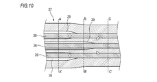
- FIG. 10 is a conceptual diagram showing an integration process according to the embodiment of the present disclosure.
- the jacket material 27 is heated to integrate the core rod 26 and the jacket material 27.
- the jacket material 27 into which the core rod 26 is inserted rotates, for example, around the central axis of the jacket material 27, and the heating source moves in the axial direction of the jacket material 27 (moves from right to left in FIG. 10). are doing.
- the jacket material 27 is heated, the inner diameter of the through hole 29 or the circular bottom hole 25 contracts due to surface tension, and the jacket material 27 is welded to the core rod 26.
- AA'in FIG. 10 indicates the position before the heating source passes.
- the core rod 26 and the jacket material 27 are not yet integrated.
- BB'in FIG. 10 indicates the position of the heating source in transit.
- the core rod 26 located on the outer peripheral core of the multi-core optical fiber 1 is already integrated with the jacket material 27.
- the jacket material 27 is not yet integrated with the core rod 26 located at the center of the multi-core optical fiber 1.
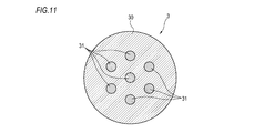
- CC'in FIG. 10 indicates the position after the heating source has passed. All core rods 26 and jacket material 27 are integrated. That is, at the position of CC'in FIG. 10, the cross-sectional structure of the multi-core optical fiber base material 3 as shown in FIG. 11 is formed, and the clad portion 30 and the core portion 31 are integrated.
- the through hole 29 or the circular bottomed hole 25 provided near the outer periphery of the jacket material 27 is provided in the center of the jacket material 27.
- the inner wall of the hole becomes smooth as the inner circumference of the hole shrinks, but the through hole 29 or the circular bottomed hole 25 provided near the outer periphery of the jacket material 27 has the through hole 29 or the circular bottom.
- the through hole 29 or the circular bottomed hole 25 may come into contact with the core rod 26 before the roughness of the inner wall of the inner wall of the hole 25 near the center of the jacket material 27 becomes sufficiently small. Further, when the clearance between the inner diameter of the through hole 29 or the circular bottom hole 25 and the outer diameter of the core rod 26 is small, the position accuracy of the core portion 31 described with reference to FIG. 11 becomes high, but the through hole 29 or the circular bottom hole 29 or the circular bottom hole is present. It becomes easy to contact the core rod 26 before the roughness of the inner wall of the bottom hole 25 becomes sufficiently small.
- the particle size of the diamond grains in the second region 52 of the cutting tool 40 is smaller than the particle size of the diamond grains in the first region 51, so that the first region 51 is a hole.
- the second region 52 reduces the roughness of the inner wall of the through hole 29 or the circular bottomed hole 25. Therefore, in the present embodiment, it is possible to obtain the multi-core optical fiber base material 3 in which air bubbles are less likely to remain at the boundary between the inner wall of the through hole 29 or the circular bottom hole 25 and the core rod 26 without impairing the productivity of drilling. it can. Then, in the present embodiment, by drawing the multi-core optical fiber base material 3 manufactured in this way, it is possible to manufacture the multi-core optical fiber 1 having less variation in outer diameter and no decrease in mechanical strength.
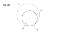
- FIGS. 12A and 12B an example of a hollow round bar-shaped cutting tool 40 has been described.
- the present disclosure is not limited to this example.
- a solid round bar-shaped cutting tool 40 as shown in FIGS. 12A and 12B may be used.
- the cutting tool 40 shown in FIG. 12A has, for example, five discharge paths 50a on the outer peripheral surface of the cutting portion 42.
- the tip surface 50 of the cutting portion 42 is, for example, conical.
- the cutting portion 42 has a smaller diameter than the through hole 29 or the circular bottomed hole 25. Then, the cutting portion 42 and the cut hole are not concentric, and the cutting portion 42 rotates about a position eccentric with respect to the center of the hole. In this case, since the cutting portion 42 has a smaller diameter than the hole, it is not necessary to provide a discharge path for the glass material.
- the tip surface 50 of the cutting portion 42 may be, for example, conical or cross-shaped.
- the method for manufacturing the multi-core optical fiber base material 3 has been described, but the present disclosure is also applicable to the case of manufacturing a single-core optical fiber base material.
- multi-core optical fiber 3 ... multi-core optical fiber base material, 10 ... clad, 11 ... core, 20 ... glass body, 21 ... one end, 22 ... other end, 23 ... ring-shaped bottomed hole, 24 ... uncut rod , 25 ... circular bottom hole, 26 ... core rod, 27 ... jacket material, 28 ... ring-shaped hole, 29 ... through hole, 30 ... clad part, 31 ... core part, 40 ... cutting tool, 41 ... shank part, 42 ... cutting portion, 50 ... tip surface, 50a ... discharge path, 51 ... first region, 52 ... second region.
Landscapes
- Engineering & Computer Science (AREA)
- Mechanical Engineering (AREA)
- Physics & Mathematics (AREA)
- Chemical & Material Sciences (AREA)
- General Physics & Mathematics (AREA)
- Optics & Photonics (AREA)
- Ceramic Engineering (AREA)
- Inorganic Chemistry (AREA)
- Life Sciences & Earth Sciences (AREA)
- General Life Sciences & Earth Sciences (AREA)
- Geochemistry & Mineralogy (AREA)
- Manufacturing & Machinery (AREA)
- Materials Engineering (AREA)
- Organic Chemistry (AREA)
- Manufacture, Treatment Of Glass Fibers (AREA)
- Polishing Bodies And Polishing Tools (AREA)
Abstract
切削工具(40)は、シャンク部(41)と、シャンク部(41)の一端に設けられた切削部(42)と、を備える。切削部(42)は、切削工具(40)の一端に設けられた第1領域(51)と、第1領域(51)よりも切削工具(40)の中央寄りに位置する第2領域(52)とを有する。第1領域(51)および第2領域(52)には、砥粒が固着される。第2領域(52)における砥粒の平均粒径が、第1領域(51)における砥粒の平均粒径よりも小さい。
Description
本開示は、切削工具および光ファイバ母材製造方法に関する。
本出願は、2019年3月28日出願の日本出願第2019-062449号に基づく優先権を主張し、前記日本出願に記載された全ての記載内容を援用するものである。
本出願は、2019年3月28日出願の日本出願第2019-062449号に基づく優先権を主張し、前記日本出願に記載された全ての記載内容を援用するものである。
長手方向に延在するコアを有した光ファイバ母材は、ロッドインコラプス法で製造されることがある。ロッドインコラプス法では、例えば円柱形状のガラス体に、長手方向に延在する孔を形成してジャケット材が作製される。次に、この孔にコアロッドを挿入した後、ジャケット材の外部から加熱してコアロッドとジャケット材を一体化して光ファイバ母材が製造される。
例えば、特許文献1は、長手方向に延在する1本のコアを有する光ファイバ母材(以下、シングルコア光ファイバ母材と称する)を製造する技術を開示している。特許文献2は、複数本のコアを有する光ファイバ母材(以下、マルチコア光ファイバ母材と称する)を製造する技術を開示している。
本開示の一態様に係る切削工具は、シャンク部と、前記シャンク部の一端に設けられた切削部と、を備える切削工具であって、前記切削部は、前記切削工具の一端に設けられた第1領域と、前記第1領域よりも前記切削工具の中央寄りに位置する第2領域とを有し、前記第1領域および前記第2領域には、砥粒が固着され、前記第2領域における砥粒の平均粒径が、前記第1領域における砥粒の平均粒径よりも小さい。
本開示の一態様に係る光ファイバ母材製造方法は、長手方向に延在するコアを有した光ファイバ母材を製造する方法であって、ガラス体の軸方向の一端から他端へ向かって、本開示の切削工具を使って孔を形成することによりジャケット材を作製し、前記孔にコアロッドを挿入し、前記ジャケット材を加熱して該ジャケット材と前記コアロッドとを一体化する。
[規則91に基づく訂正 27.03.2020]
[本開示が解決しようとする課題]
シングルコア光ファイバ母材を製造するためのジャケットパイプでは、孔はジャケットパイプの中心に設けられる。ジャケットパイプが外部から加熱された場合、ジャケットパイプはジャケットパイプの中心軸に対して対称な状態を保ったまま変形する。つまり、孔の内周は孔の中心軸に向かって一様に縮小し、孔の内壁がコアロッドに接触する。この孔の内周の縮小と同時に孔の内壁が平滑になる。しかし、仮に孔の内壁の粗さが十分に小さくなる前に孔の内壁がコアロッドに接触すると、孔の内壁とコアロッドとの境界部分に気泡が残ることがある。気泡が存在する光ファイバ母材を線引きすると、光ファイバの外径変動が大きくなり、光ファイバの機械強度が低下する。
マルチコア光ファイバ母材がロッドインコラプス法で製造される場合、孔の内径とコアロッドの外径とのクリアランスが小さいと、コアの位置精度が高くなる。しかし、クリアランスが小さいと、孔の内壁の粗さが十分に小さくなる前に孔の内壁がコアロッドに接触しやすくなるので、気泡が残りやすくなる。
マルチコア光ファイバ母材には、孔を、ジャケットパイプの中心以外に設けたものがある。ジャケットパイプが外部から加熱された場合、ジャケットパイプの中心よりもジャケットパイプの外周近傍が強く加熱される。このため、ジャケットパイプの一断面において、ジャケットパイプの中心以外にある孔の内壁の粗さを内壁全周で等しく保つのは難しい。特に、ジャケットパイプの外周近傍に設けた孔では、孔の内壁のうちジャケットパイプの中心に近い部分の内壁の粗さが十分に小さくなる前に孔の内壁がコアロッドに接触し得るので、気泡が残りやすくなる。
[本開示の実施形態の説明]
最初に本開示の実施形態の内容を列記して説明する。
(1)シャンク部と、前記シャンク部の一端に設けられた切削部と、を備える切削工具であって、前記切削部は、前記切削工具の一端に設けられた第1領域と、前記第1領域よりも前記切削工具の中央寄りに位置する第2領域とを有し、前記第1領域および前記第2領域には、砥粒が固着され、前記第2領域における砥粒の平均粒径が、前記第1領域における砥粒の平均粒径よりも小さい。第2領域における砥粒の粒径が、第1領域における砥粒の粒径よりも小さいので、本開示は、第1領域では孔開けの生産性を確保しつつ、第2領域では孔の内壁の粗さを小さくすることができる。よって本開示は、孔開けの生産性を損なうことなく、孔の内壁とコアロッドとの境界部分に気泡が残りにくい光ファイバ母材を得ることができる。
(2)本開示の切削工具の一態様では、前記砥粒がダイヤモンド粒である。ダイヤモンド粒を用いれば、平滑な内壁を有した孔がガラス体に容易に形成される。
(3)本開示の切削工具の一態様では、前記第1領域における前記砥粒の平均粒径が100μm以上であり、前記第2領域における前記砥粒の平均粒径が100μm未満である。第1領域における砥粒の平均粒径が100μm以上であるので、本開示は、孔開けの加工速度を高速に維持できる。さらに、第2領域における砥粒の平均粒径が100μm未満なので、本開示は上記加工速度でも平滑な内壁を得られる。
(4)本開示の切削工具の一態様では、前記第2領域の外径が、前記第1領域の外径よりも大きい。第2領域の外径が第1領域の外径よりも大きいので、第1領域が孔を加工した後に、第2領域が孔の内壁を確実に加工できる。よって本開示は、平滑な内壁を有した孔を確実に得ることができる。
(5)本開示の切削工具の一態様では、前記第2領域の外径と前記第1領域の外径との差が、10μm以上300μm以下の範囲である。第2領域の外径と第1領域の外径との差が10μm以上であるので、仮に第2領域の砥粒が摩耗しても、第2領域は孔の内壁の加工を続けることができる。さらに、第2領域の外径と第1領域の外径との差が300μm以下であるので、加工時における第2領域への負荷が大きくならず、第2領域の砥粒の摩耗が低減する。
(6)本開示の一態様に係る光ファイバ母材製造方法は、長手方向に延在するコアを有した光ファイバ母材を製造する方法であって、当該方法は、ガラス体の軸方向の一端から他端へ向かって、本開示の切削工具を使って孔を形成することによりジャケット材を作製し、前記孔にコアロッドを挿入し、前記ジャケット材を加熱して該ジャケット材と前記コアロッドとを一体化する。第2領域における砥粒の平均粒径が、第1領域における砥粒の平均粒径よりも小さいので、本開示は、第1領域では孔開けの生産性を確保しつつ、第2領域では孔の内壁の粗さを小さくすることができる。よって本開示は、孔開けの生産性を損なうことなく、孔の内壁とコアロッドとの境界部分に気泡が残りにくい光ファイバ母材を得ることができる。そして本開示は、このように製造された光ファイバ母材を線引きすれば、光ファイバの外径変動が少なく、かつ機械強度の低下のない光ファイバを製造することができる。
[本開示の効果]
本開示は、孔開けの生産性を損なうことなく、孔の内壁とコアロッドとの境界部分に気泡が残りにくい光ファイバ母材製造方法、切削工具を提供することを目的とする。
[本開示の実施形態の詳細]
本開示は、孔開けの生産性を損なうことなく、孔の内壁とコアロッドとの境界部分に気泡が残りにくい光ファイバ母材製造方法、切削工具を提供することを目的とする。
[本開示の実施形態の詳細]
以下、添付図面を参照しながら、本開示による光ファイバ母材製造方法、切削工具の好適な実施の形態について説明する。
図1は、マルチコア光ファイバ1の一例を示す断面図である。マルチコア光ファイバ1は、クラッド10内に例えば7個のコア11を有する。コア11は、マルチコア光ファイバ1の長手方向に延在する。コア11は、光ファイバ中心軸上に配置された中心コアと、光ファイバ中心軸の周囲の六角形の頂点上に配置された外周コアを含む。各コア11は、クラッド10の屈折率よりも高い屈折率を有する領域を含んでおり、光を伝搬するよう構成されている。
光ファイバ母材製造方法の一つとしてロッドインコラプス法がある。ロッドインコラプス法は、例えば円柱形状のガラス体の軸方向の一端から他端へ向かって、孔を形成することによりジャケット材を作製する工程と、ジャケット材の孔にコアロッドを挿入する工程と、ジャケット材を加熱してジャケット材とコアロッドとを一体化する工程と、を有する。
図2Aは、本開示の一態様に係る光ファイバ母材製造方法で使用するガラス体20の一端21から見た正面図である。図2Bは、図2AのX-X線矢視断面図である。ガラス体20は、例えばフッ素が添加されたシリカガラス、あるいは純シリカガラスであり、円柱形状である。マルチコア光ファイバ1を得るために、ロッドインコラプス法で光ファイバ母材が製造される場合、ガラス体20には、軸方向の一端21から他端22に向かう7個の孔が、ドリル状の工具で設けられる。
図3Aから図3Cは、本開示の一態様に係る光ファイバ母材製造方法に使用される切削工具40を説明する図である。図3Aは、切削工具40の一例を示す側面図である。図3Bは、切削工具40の一例を示す正面図である。図3Cは、切削工具40の、砥粒が固着している切削部を拡大した斜視図である。切削工具40は、シャンク部41と、切削部42とを備える。シャンク部41は、例えば金属製の中空丸棒であり、長手方向に延びた軸線回りの回転力がシャンク部41に付与されるように構成されている。切削部42は、シャンク部41の前方(切削工具40の一端であって、図3Aにおいては右側)に位置しており、シャンク部41とともに回転するよう構成されている。
切削部42は、例えば中空丸棒であり、切削部42の断面上において中心に、シャンク部41と同心の排出路50aが設けられている。切削部42の外周面は、切削工具40の一端に設けられた第1領域51と、第1領域51よりも切削工具40の中央寄りに位置する第2領域52とを有する。具体的には、第2領域52は、第1領域51よりも後方(図3Aにおいて左側)に位置する。第2領域52の前端は、例えば第1領域51の後端に連結している。第1領域51の長さL1および第2領域52の長さL2はいずれも例えば5mmである。第1領域51(先端面50を含む)および第2領域52には、砥粒(例えばダイヤモンド粒)が例えば多層の電着構造によって固着されている。
砥粒の平均粒径は、JIS_B_4130で規定されている粒度により評価される。第1領域51におけるダイヤモンド粒の平均粒径は100μm以上(JIS_B_4130における粒度表示で#140以下)、好ましくは、150μm以上(JIS_B_4130における粒度表示で#100以下)である。第2領域52におけるダイヤモンド粒の平均粒径は、第1領域51におけるダイヤモンド粒の平均粒径よりも小さい。詳しくは、第2領域52におけるダイヤモンド粒の平均粒径は100μm未満、好ましくは、50μm以下(JIS_B_4130における粒度表示で#270以上)である。平均粒径は、例えば複数種類のふるいによって粒子を選別する方法で一般的に定められる。平均粒径105μmが粒度表示#140に、平均粒径149μmが#100に、平均粒径53μmが#270にそれぞれ相当する。
このように、第1領域51におけるダイヤモンド粒の平均粒径が100μm以上であるので、本実施形態は、孔開けの加工速度を高速に維持できる。第1領域51におけるダイヤモンド粒の平均粒径が150μm以上であれば、本実施形態は、孔開けの加工速度をより一層大きくすることができる。さらに、第2領域52におけるダイヤモンド粒の平均粒径が100μm未満なので、本実施形態は、上記加工速度でも平滑な孔の内壁を得られる。第2領域52におけるダイヤモンド粒の平均粒径が50μm以下であれば、本実施形態は、孔の内壁をより一層滑らかにすることができる。
切削部42に固着された砥粒は、ドレッシングによって突き出し量が調整されて切れ刃が形成される。ダイヤモンドは、合成ダイヤモンドでもよいし天然ダイヤモンドでもよい。ダイヤモンドはガラスの加工に好適であるが、本開示の砥粒には、CBN(Cubic Boron Nitride:立方晶窒化ホウ素)を用いてもよい。
図示の例では、第1領域51と第2領域52とが連結した例を挙げて説明した。しかし、砥粒が固着しない領域を第1領域51と第2領域52の間に設けて、第1領域51と第2領域52とが互いに離して配置されてもよい。本実施形態は第1領域51と第2領域52の2つの領域には限定されず、砥粒を固着した領域が3つ以上設けられてもよい。この場合、最も後方に位置する領域における砥粒の平均粒径が最も小さい。
ガラス体20に孔を設ける切削部42において、第2領域52の外径と第1領域51の外径は同じ大きさであってもよい。しかし、図3Cに示すように好ましくは、第2領域52の外径D2が第1領域51の外径D1よりも大きい。第1領域51が孔をガラス体20に設けた後に、第2領域がこの孔の内壁を確実に加工できるからである。これにより本実施形態は、平滑な内壁を有した孔を得ることができる。
具体的には、第2領域52の外径D2と第1領域51の外径D1との差(D2-D1)は、10μm以上300μm以下の範囲である。第2領域52の外径D2と第1領域51の外径D1との差が10μm以上であるので、切削工具40の複数回の使用によって、仮に第2領域52のダイヤモンド粒が摩耗しても、第2領域52は孔の内壁の加工を続けることができる。加えて、第2領域52の外径D2と第1領域51の外径D1との差が300μm以下であるので、加工時における第2領域52への負荷が大きくならず、第2領域52のダイヤモンド粒の摩耗が低減する。
ガラス体20に、図1で説明した7個のコア11と同じ位置に計7個の孔が形成される場合、切削工具40は回転駆動され、前方に配置された切削部42を先頭にして、ガラス体20の一端21から他端22へ向かってガラス体20の内部に切削工具40が挿入される。切削部42で切削されたガラス材は例えば排出路50aから後方に送られて排出される。
図4から図6は、光ファイバ母材の製造方法における、ガラス体20およびジャケット材27の中心軸を含む断面図である。中空丸棒状の切削工具40により、ガラス体20に計7個のリング状孔28が形成される。図4は、計7個のうち、断面上の3個のリング状孔28が形成される中間工程を示す。各リング状孔28の中心には、削り残しの棒24が残っている。リング状孔28が他端22に到達すると、棒24は脱落し、リング状孔28は貫通孔29となる(図5)。貫通孔29が本開示の孔に相当する。フッ素系のガス等を用いて貫通孔29の内表面が洗浄される。
次いで、計7本のコアロッド26が貫通孔29にそれぞれ挿入される。図6は断面上の3本のコアロッド26を示す。この場合、例えば、マルチコア光ファイバ1の中心に位置するコアロッド26は、ジャケット材27の中心軸上に配置された貫通孔29と同心に配置される。また、マルチコア光ファイバ1の外周コアに位置する複数のコアロッド26は、それぞれ対応する貫通孔29においてジャケット材27の中心軸寄りに配置される。
なお、本開示の孔は貫通していなくてもよい。この場合、ガラス体20に、計7個のリング状有底孔23が形成される。図7は、断面上の3個のリング状有底孔23を示す。リング状有底孔23が本開示の孔に相当する。リング状有底孔23は、長手方向に沿って延びており、他端22から所定厚みを残した位置まで達している。ガラス体20内には、リング状有底孔23で囲まれた、削り残しの棒24が残っている。
次に、ガラス体20を外部から加熱すると、棒24の底部分が軟化・溶融するので、棒24の底部分を切断すれば、ガラス体20内には、円状有底孔25が形成される(図8)。続いて、例えば揉み付けツールが用いられ、あるいは二酸化炭素レーザが照射されて、円状有底孔25の底部分の残渣が取り除かれる。その後、フッ素系のガス等を用いて円状有底孔25内が洗浄されてジャケット材27が形成される。
次いで、計7本のコアロッド26が円状有底孔25にそれぞれ挿入される。図9は、断面上の3本のコアロッド26を示す。この場合、例えば、マルチコア光ファイバ1の中心に位置するコアロッド26は、ジャケット材27の中心軸上に配置された円状有底孔25と同心に配置される。また、マルチコア光ファイバ1の外周コアに位置する複数のコアロッド26は、それぞれ対応する円状有底孔25においてジャケット材27の中心軸寄りに配置される。
コアロッド26は、ジャケット材27よりも屈折率が高いガラス棒であり、VAD(Vapor Phase Axial Deposition)法等の気相ガラス合成法により作製される。ジャケット材27が、フッ素が添加されたシリカガラスである場合、コアロッド26には、純シリカガラス(塩素を含んでもよい)を含む中心コアと、この中心コアの周囲を取り囲み、フッ素が添加されたシリカガラスを含む光学クラッドを含むコアロッドが用いられる。一方、ジャケット材27が純シリカガラスの場合、コアロッド26には、GeO2が添加されたシリカガラスを含む中心コアと、この中心コアの周囲を取り囲み、GeO2が添加されていない純シリカガラスを含む光学クラッドを含むコアロッドが用いられる。
図10は、本開示の実施形態に係る一体化する工程を示す概念図である。次に、ジャケット材27が加熱されてコアロッド26とジャケット材27が一体化する。詳しくは、コアロッド26が挿入されたジャケット材27は、例えばジャケット材27の中心軸周りに回転しており、加熱源は、ジャケット材27の軸線方向に移動(図10では右から左へ移動)している。ジャケット材27が加熱されると、貫通孔29または円状有底孔25の内径は表面張力によって収縮し、ジャケット材27はコアロッド26に溶着する。
図10のA-A’は、加熱源が通過する前の位置を示す。コアロッド26およびジャケット材27は未だ一体化していない。図10のB-B’は、加熱源の通過中の位置を示す。マルチコア光ファイバ1の外周コアに位置するコアロッド26は、ジャケット材27と既に一体化している。しかし、マルチコア光ファイバ1の中心に位置するコアロッド26は、ジャケット材27は未だ一体化していない。図10のC-C’は、加熱源が通過した後の位置を示す。すべてのコアロッド26およびジャケット材27が一体化している。つまり、図10のC-C’の位置では、図11に示すようなマルチコア光ファイバ母材3の断面構造となっており、クラッド部30とコア部31が一体になる。
このように、ロッドインコラプス法では、ジャケット材27の外周が加熱源に近いので、ジャケット材27の外周がジャケット材27の中心よりも早く加熱されて変形が進む。このため、図10のB-B’の位置で説明したように、ジャケット材27の外周近傍に設けた貫通孔29または円状有底孔25が、ジャケット材27の中心に設けた貫通孔29または円状有底孔25よりも先に縮小する。一般的に、孔の内周の収縮とともに、穴の内壁が平滑になるが、ジャケット材27の外周近傍に設けた貫通孔29または円状有底孔25では、貫通孔29または円状有底孔25の内壁のうちジャケット材27の中心に近い部分の内壁の粗さが十分に小さくなる前に貫通孔29または円状有底孔25がコアロッド26に接触し得る。また、貫通孔29または円状有底孔25の内径とコアロッド26の外径とのクリアランスが小さい場合、図11で説明したコア部31の位置精度が高くなるが、貫通孔29または円状有底孔25の内壁の粗さが十分に小さくなる前にコアロッド26に接触しやすくなる。
しかしながら、図3Aから図3Cで説明したように、切削工具40の第2領域52におけるダイヤモンド粒の粒径が、第1領域51におけるダイヤモンド粒の粒径よりも小さいので、第1領域51は孔開けの生産性を確保し、第2領域52は貫通孔29または円状有底孔25の内壁の粗さを小さくする。よって本実施形態は、孔開けの生産性を損なうことなく、貫通孔29または円状有底孔25の内壁とコアロッド26との境界部分に気泡が残りにくいマルチコア光ファイバ母材3を得ることができる。そして本実施形態は、このように製造されたマルチコア光ファイバ母材3を線引きすれば、外径変動が少なく、かつ機械強度の低下のないマルチコア光ファイバ1を製造することができる。
上記実施例では、中空丸棒状の切削工具40の例を挙げて説明した。しかし、本開示はこの例に限定されない。例えば、図12A、図12Bに示すような中実丸棒状の切削工具40であってもよい。図12Aに示した切削工具40は、切削部42の外周面に例えば5本の排出路50aを有している。切削部42の先端面50は例えば円錐状である。
図12Bに示した切削工具40は、切削部42が貫通孔29または円状有底孔25よりも小径である。そして、切削部42と切削された孔とが同心ではなく、切削部42は孔の中心に対して偏心した位置を中心にして回転する。この場合、切削部42が孔よりも小径であるので、ガラス材の排出路は設けられなくてもよい。切削部42の先端面50は例えば円錐状であってもよく十字状にしてもよい。
上記実施例では、マルチコア光ファイバ母材3の製造方法を説明したが、本開示はシングルコア光ファイバ母材を製造する場合にも適用可能である。
今回開示された実施の形態はすべての点で例示であって制限的なものではないと考えられるべきである。本開示の範囲は、上記した意味ではなく、請求の範囲によって示され、請求の範囲と均等の意味および範囲内でのすべての変更が含まれることが意図される。
1…マルチコア光ファイバ、3…マルチコア光ファイバ母材、10…クラッド、11…コア、20…ガラス体、21…一端、22…他端、23…リング状有底孔、24…削り残しの棒、25…円状有底孔、26…コアロッド、27…ジャケット材、28…リング状孔、29…貫通孔、30…クラッド部、31…コア部、40…切削工具、41…シャンク部、42…切削部、50…先端面、50a…排出路、51…第1領域、52…第2領域。
Claims (6)
- シャンク部と、
前記シャンク部の一端に設けられた切削部と、を備える切削工具であって、
前記切削部は、前記切削工具の一端に設けられた第1領域と、前記第1領域よりも前記切削工具の中央寄りに位置する第2領域とを有し、
前記第1領域および前記第2領域には、砥粒が固着され、
前記第2領域における砥粒の平均粒径が、前記第1領域における砥粒の平均粒径よりも小さい、切削工具。 - 前記砥粒がダイヤモンド粒である、請求項1に記載の切削工具。
- 前記第1領域における前記砥粒の平均粒径が100μm以上であり、前記第2領域における前記砥粒の平均粒径が100μm未満である、請求項1または請求項2に記載の切削工具。
- 前記第2領域の外径が、前記第1領域の外径よりも大きい、請求項1から請求項3のいずれか一項に記載の切削工具。
- 前記第2領域の外径と前記第1領域の外径との差が、10μm以上300μm以下の範囲である、請求項4に記載の切削工具。
- 長手方向に延在するコアを有した光ファイバ母材を製造する方法であって、
ガラス体の軸方向の一端から他端へ向かって、請求項1から請求項5のいずれか一項に記載の切削工具を使って孔を形成することによりジャケット材を作製し、
前記孔にコアロッドを挿入し、
前記ジャケット材を加熱して該ジャケット材と前記コアロッドとを一体化する、光ファイバ母材製造方法。
Priority Applications (3)
| Application Number | Priority Date | Filing Date | Title |
|---|---|---|---|
| CN202080022921.1A CN113613841B (zh) | 2019-03-28 | 2020-03-17 | 切削工具以及光纤母材制造方法 |
| JP2021509129A JPWO2020196104A1 (ja) | 2019-03-28 | 2020-03-17 | |
| US17/483,970 US20220011499A1 (en) | 2019-03-28 | 2021-09-24 | Cutting tool and method for manufacturing optical fiber preform |
Applications Claiming Priority (2)
| Application Number | Priority Date | Filing Date | Title |
|---|---|---|---|
| JP2019-062449 | 2019-03-28 | ||
| JP2019062449 | 2019-03-28 |
Related Child Applications (1)
| Application Number | Title | Priority Date | Filing Date |
|---|---|---|---|
| US17/483,970 Continuation US20220011499A1 (en) | 2019-03-28 | 2021-09-24 | Cutting tool and method for manufacturing optical fiber preform |
Publications (1)
| Publication Number | Publication Date |
|---|---|
| WO2020196104A1 true WO2020196104A1 (ja) | 2020-10-01 |
Family
ID=72610893
Family Applications (1)
| Application Number | Title | Priority Date | Filing Date |
|---|---|---|---|
| PCT/JP2020/011788 WO2020196104A1 (ja) | 2019-03-28 | 2020-03-17 | 切削工具および光ファイバ母材製造方法 |
Country Status (4)
| Country | Link |
|---|---|
| US (1) | US20220011499A1 (ja) |
| JP (1) | JPWO2020196104A1 (ja) |
| CN (1) | CN113613841B (ja) |
| WO (1) | WO2020196104A1 (ja) |
Citations (3)
| Publication number | Priority date | Publication date | Assignee | Title |
|---|---|---|---|---|
| JPS5641953Y2 (ja) * | 1978-03-03 | 1981-10-01 | ||
| JPH02117861U (ja) * | 1989-03-09 | 1990-09-20 | ||
| JP2014159348A (ja) * | 2013-02-20 | 2014-09-04 | Sumitomo Electric Ind Ltd | マルチコア光ファイバ母材製造方法 |
Family Cites Families (4)
| Publication number | Priority date | Publication date | Assignee | Title |
|---|---|---|---|---|
| US20070269282A1 (en) * | 2006-05-18 | 2007-11-22 | Agapiou John S | System and method of boring a pre-formed guide in a single pass |
| FR2975027B1 (fr) * | 2011-05-10 | 2014-04-18 | Snecma | Outil de percage de trous dans une piece, notamment en materiau composite a matrice organique, procede de percage correspondant |
| TW201325823A (zh) * | 2011-12-30 | 2013-07-01 | Metal Ind Res & Dev Ct | 磨削工具及其製作方法 |
| DE102013106612A1 (de) * | 2013-06-25 | 2015-01-08 | Schott Ag | Werkzeugkrone und mit der Werkzeugkrone herstellbares Glaskeramik-Erzeugnis |
-
2020
- 2020-03-17 CN CN202080022921.1A patent/CN113613841B/zh active Active
- 2020-03-17 JP JP2021509129A patent/JPWO2020196104A1/ja active Pending
- 2020-03-17 WO PCT/JP2020/011788 patent/WO2020196104A1/ja active Application Filing
-
2021
- 2021-09-24 US US17/483,970 patent/US20220011499A1/en active Pending
Patent Citations (3)
| Publication number | Priority date | Publication date | Assignee | Title |
|---|---|---|---|---|
| JPS5641953Y2 (ja) * | 1978-03-03 | 1981-10-01 | ||
| JPH02117861U (ja) * | 1989-03-09 | 1990-09-20 | ||
| JP2014159348A (ja) * | 2013-02-20 | 2014-09-04 | Sumitomo Electric Ind Ltd | マルチコア光ファイバ母材製造方法 |
Also Published As
| Publication number | Publication date |
|---|---|
| US20220011499A1 (en) | 2022-01-13 |
| JPWO2020196104A1 (ja) | 2020-10-01 |
| CN113613841B (zh) | 2024-03-26 |
| CN113613841A (zh) | 2021-11-05 |
Similar Documents
| Publication | Publication Date | Title |
|---|---|---|
| CN102438784A (zh) | 在刃缘与次级切削刃之间带有负轴向前刀面过渡部分的麻花钻头 | |
| KR20140127752A (ko) | 하이브리드 절삭공구, 칩 이송부 및 절삭공구를 제조하기 위한 방법 | |
| US6196908B1 (en) | Drill for composite materials | |
| WO2020196104A1 (ja) | 切削工具および光ファイバ母材製造方法 | |
| CN114127022A (zh) | 制造空芯光纤和空芯光纤预制件的方法 | |
| CN113939482A (zh) | 制造空芯光纤和空芯光纤预制件的方法 | |
| CN114007991A (zh) | 制造空芯光纤和空芯光纤预制件的方法 | |
| CN104249310B (zh) | 平头刀具和能用该平头刀具制造的玻璃或玻璃陶瓷制品 | |
| JP2001220164A (ja) | 微細構造光ファイバ用母材及び微細構造光ファイバの製造方法 | |
| CN114026049A (zh) | 制造空芯光纤和空芯光纤预制件的方法 | |
| US20090117517A1 (en) | Dental crown preparation instrument and method for producing same | |
| CN114026048A (zh) | 制造空芯光纤和空芯光纤预制件的方法 | |
| CN108176896B (zh) | 用于高精密深孔加工的挤光铰刀 | |
| US6766662B2 (en) | Method of manufacturing glass parts for connecting optical fibers, and glass parts for connecting optical fibers manufactured using the methods | |
| JP4026319B2 (ja) | 部品成形用工具の加工方法及びこの加工方法を用いて製造された部品成形用工具 | |
| JP2001047345A (ja) | 細孔加工方法 | |
| JP6953391B2 (ja) | 複数の竿体が継合される釣竿 | |
| US20040144133A1 (en) | Methods for joining glass preforms in optical fiber manufacturing | |
| KR102177689B1 (ko) | 샤프트 가공 장치 | |
| US20210213543A1 (en) | Drill tip and method for producing a drill tip | |
| JP4374161B2 (ja) | 光学レンズ又はその金型の切削加工方法 | |
| CN105921793A (zh) | 一种钻头及其制造方法 | |
| JP2001106542A (ja) | 変形第1クラッドを有する光ファイバ母材の製造方法及び光ファイバ母材並びに光ファイバ | |
| JP5513356B2 (ja) | 光ファイバ用母材の製造方法、及び、これを用いた光ファイバの製造方法 | |
| JP2006044950A (ja) | 光ファイバ母材の製造方法 |
Legal Events
| Date | Code | Title | Description |
|---|---|---|---|
| 121 | Ep: the epo has been informed by wipo that ep was designated in this application |
Ref document number: 20779340 Country of ref document: EP Kind code of ref document: A1 |
|
| ENP | Entry into the national phase |
Ref document number: 2021509129 Country of ref document: JP Kind code of ref document: A |
|
| NENP | Non-entry into the national phase |
Ref country code: DE |
|
| 122 | Ep: pct application non-entry in european phase |
Ref document number: 20779340 Country of ref document: EP Kind code of ref document: A1 |