EP2818117A1 - Object information obtaining system, signal processing method, and program - Google Patents
Object information obtaining system, signal processing method, and program Download PDFInfo
- Publication number
- EP2818117A1 EP2818117A1 EP14171887.4A EP14171887A EP2818117A1 EP 2818117 A1 EP2818117 A1 EP 2818117A1 EP 14171887 A EP14171887 A EP 14171887A EP 2818117 A1 EP2818117 A1 EP 2818117A1
- Authority
- EP
- European Patent Office
- Prior art keywords
- object information
- frequency signal
- acoustic waves
- phase modulation
- wave number
- Prior art date
- Legal status (The legal status is an assumption and is not a legal conclusion. Google has not performed a legal analysis and makes no representation as to the accuracy of the status listed.)
- Withdrawn
Links
Images


Classifications
-
- A—HUMAN NECESSITIES
- A61—MEDICAL OR VETERINARY SCIENCE; HYGIENE
- A61B—DIAGNOSIS; SURGERY; IDENTIFICATION
- A61B5/00—Measuring for diagnostic purposes; Identification of persons
- A61B5/0093—Detecting, measuring or recording by applying one single type of energy and measuring its conversion into another type of energy
- A61B5/0095—Detecting, measuring or recording by applying one single type of energy and measuring its conversion into another type of energy by applying light and detecting acoustic waves, i.e. photoacoustic measurements
-
- A—HUMAN NECESSITIES
- A61—MEDICAL OR VETERINARY SCIENCE; HYGIENE
- A61B—DIAGNOSIS; SURGERY; IDENTIFICATION
- A61B5/00—Measuring for diagnostic purposes; Identification of persons
- A61B5/72—Signal processing specially adapted for physiological signals or for diagnostic purposes
- A61B5/7203—Signal processing specially adapted for physiological signals or for diagnostic purposes for noise prevention, reduction or removal
-
- A—HUMAN NECESSITIES
- A61—MEDICAL OR VETERINARY SCIENCE; HYGIENE
- A61B—DIAGNOSIS; SURGERY; IDENTIFICATION
- A61B5/00—Measuring for diagnostic purposes; Identification of persons
- A61B5/72—Signal processing specially adapted for physiological signals or for diagnostic purposes
- A61B5/7228—Signal modulation applied to the input signal sent to patient or subject; Demodulation to recover the physiological signal
-
- A—HUMAN NECESSITIES
- A61—MEDICAL OR VETERINARY SCIENCE; HYGIENE
- A61B—DIAGNOSIS; SURGERY; IDENTIFICATION
- A61B5/00—Measuring for diagnostic purposes; Identification of persons
- A61B5/74—Details of notification to user or communication with user or patient; User input means
- A61B5/742—Details of notification to user or communication with user or patient; User input means using visual displays
-
- A—HUMAN NECESSITIES
- A61—MEDICAL OR VETERINARY SCIENCE; HYGIENE
- A61B—DIAGNOSIS; SURGERY; IDENTIFICATION
- A61B8/00—Diagnosis using ultrasonic, sonic or infrasonic waves
- A61B8/42—Details of probe positioning or probe attachment to the patient
- A61B8/4209—Details of probe positioning or probe attachment to the patient by using holders, e.g. positioning frames
-
- A—HUMAN NECESSITIES
- A61—MEDICAL OR VETERINARY SCIENCE; HYGIENE
- A61B—DIAGNOSIS; SURGERY; IDENTIFICATION
- A61B8/00—Diagnosis using ultrasonic, sonic or infrasonic waves
- A61B8/42—Details of probe positioning or probe attachment to the patient
- A61B8/4272—Details of probe positioning or probe attachment to the patient involving the acoustic interface between the transducer and the tissue
- A61B8/429—Details of probe positioning or probe attachment to the patient involving the acoustic interface between the transducer and the tissue characterised by determining or monitoring the contact between the transducer and the tissue
-
- A—HUMAN NECESSITIES
- A61—MEDICAL OR VETERINARY SCIENCE; HYGIENE
- A61B—DIAGNOSIS; SURGERY; IDENTIFICATION
- A61B8/00—Diagnosis using ultrasonic, sonic or infrasonic waves
- A61B8/52—Devices using data or image processing specially adapted for diagnosis using ultrasonic, sonic or infrasonic waves
- A61B8/5207—Devices using data or image processing specially adapted for diagnosis using ultrasonic, sonic or infrasonic waves involving processing of raw data to produce diagnostic data, e.g. for generating an image
-
- A—HUMAN NECESSITIES
- A61—MEDICAL OR VETERINARY SCIENCE; HYGIENE
- A61B—DIAGNOSIS; SURGERY; IDENTIFICATION
- A61B8/00—Diagnosis using ultrasonic, sonic or infrasonic waves
- A61B8/52—Devices using data or image processing specially adapted for diagnosis using ultrasonic, sonic or infrasonic waves
- A61B8/5269—Devices using data or image processing specially adapted for diagnosis using ultrasonic, sonic or infrasonic waves involving detection or reduction of artifacts
-
- G—PHYSICS
- G01—MEASURING; TESTING
- G01S—RADIO DIRECTION-FINDING; RADIO NAVIGATION; DETERMINING DISTANCE OR VELOCITY BY USE OF RADIO WAVES; LOCATING OR PRESENCE-DETECTING BY USE OF THE REFLECTION OR RERADIATION OF RADIO WAVES; ANALOGOUS ARRANGEMENTS USING OTHER WAVES
- G01S7/00—Details of systems according to groups G01S13/00, G01S15/00, G01S17/00
- G01S7/52—Details of systems according to groups G01S13/00, G01S15/00, G01S17/00 of systems according to group G01S15/00
- G01S7/52017—Details of systems according to groups G01S13/00, G01S15/00, G01S17/00 of systems according to group G01S15/00 particularly adapted to short-range imaging
- G01S7/52046—Techniques for image enhancement involving transmitter or receiver
- G01S7/52049—Techniques for image enhancement involving transmitter or receiver using correction of medium-induced phase aberration
-
- A—HUMAN NECESSITIES
- A61—MEDICAL OR VETERINARY SCIENCE; HYGIENE
- A61B—DIAGNOSIS; SURGERY; IDENTIFICATION
- A61B8/00—Diagnosis using ultrasonic, sonic or infrasonic waves
- A61B8/08—Clinical applications
- A61B8/0825—Clinical applications for diagnosis of the breast, e.g. mammography
-
- A—HUMAN NECESSITIES
- A61—MEDICAL OR VETERINARY SCIENCE; HYGIENE
- A61B—DIAGNOSIS; SURGERY; IDENTIFICATION
- A61B8/00—Diagnosis using ultrasonic, sonic or infrasonic waves
- A61B8/40—Positioning of patients, e.g. means for holding or immobilising parts of the patient's body
- A61B8/403—Positioning of patients, e.g. means for holding or immobilising parts of the patient's body using compression means
Definitions
- the present invention relates to an object information obtaining system, a signal processing method, and a program.
- Object information obtaining systems such as photoacoustic imaging apparatuses or ultrasonic echo imaging apparatuses have been developed thus far as technologies for obtaining information inside an object, such as a living body, by detecting acoustic waves.
- the acoustic waves are refracted. Detection signals of the refracted acoustic waves provide a low quantitativeness of object information. When the object information is converted into an image, the image consequently has distortion or a low contrast.
- the effect of the non-uniformity of the sound velocity has to be minimized.
- the following method is included as an example of a method for reducing the effect of the non-uniformity of the sound velocity.
- Japanese Patent Laid-Open No. 2010-167258 discloses a method for correcting the effect of refraction by tracing the propagation paths of acoustic waves in accordance with the Snell's law and calculating the arrival time from the propagation distance of the acoustic waves.
- Japanese Patent Laid-Open No. 2010-167258 involves tracing of the propagation paths of multiple sound rays of acoustic waves, which have occurred as spherical waves, in accordance with the Snell's law and thus requires a large number of calculations. Consequently, the method described in Japanese Patent Laid-Open No. 2010-167258 is unsuitable for accelerating the calculations for correcting the effect of refraction.
- the present invention was made in view of the above-described problems.
- the present invention provides an object information obtaining system that can reduce the effect of the non-uniformity of the sound velocity with a small calculation amount.
- An object information obtaining system disclosed herein includes a holding member that holds an object; a probe that detects acoustic waves at a plurality of positions and obtains a plurality of time-series detection signals, the acoustic waves having occurred inside the object and having propagated through the holding member; and a signal processor that obtains a first frequency signal on the basis of the plurality of time-series detection signals, that obtains a second frequency signal, in which phase modulation is corrected, by performing, on the first frequency signal, correction of phase modulation of the acoustic waves due to the holding member, and that obtains object information inside the object on the basis of the second frequency signal, in which the phase modulation is corrected.
- a first embodiment describes a photoacoustic system, which is an example of an object information obtaining system, in detail below referring to the drawings.
- the photoacoustic system is a system that obtains object information from detection signals of photoacoustic waves that have occurred due to a photoacoustic effect.
- the object information obtainable from detection signals of photoacoustic waves include the initial acoustic pressure of photoacoustic waves, the light energy absorbance of photoacoustic waves, the absorption coefficient of photoacoustic waves, and the concentration of materials constituting the object.
- the concentration of materials include an oxygen saturation, an oxyhemoglobin concentration, a deoxyhemoglobin concentration, and a total hemoglobin concentration.
- the total hemoglobin concentration is the sum of the oxyhemoglobin concentration and the deoxyhemoglobin concentration.
- the object information does not have to be numerical data and may be information of distribution of positions inside the object.
- the object information may also include distribution information such as the distribution of the absorption coefficient or the distribution of the oxygen saturation.
- the present invention is applicable to not only a photoacoustic system but also an acoustic-wave echo device that obtains object information by detecting echoes of the acoustic waves.
- the object information obtainable from detection signals of echoes of acoustic waves include a brightness mode (B-mode) image that represents the distribution of the strength of echoes of acoustic waves.
- B-mode brightness mode
- examples of the object information may include a Doppler-mode image, which represents the velocity distribution of a structure in the object, an elastography image, which represents the elasticity distribution (distortion factor, distortional wave velocity, or Young's modulus) in the structure of the object, and speckle pattern data attributable to scattering of acoustic waves inside the object.
- Fig. 1 schematically illustrates an object information obtaining system according to the embodiment. Now, components of the system will be described.
- the object information obtaining system includes a light source 110, an optical system 120, a holding member 130, a probe 140 including multiple transducers 141, a signal processor 150 serving as a computer, and a display unit 160.
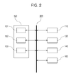
- Fig. 2 schematically illustrates the details of the signal processor 150 and components around the signal processor 150.
- the signal processor 150 includes a controller 151, a computation unit 152, and a memory unit 153.
- the controller 151 controls operations of the components constituting the object information obtaining system via a bus 200.
- the controller 151 also reads a program that describes a method for obtaining object information, which will be described below, stored in the memory unit 153, so that the object information obtaining system executes the method for obtaining object information.
- the holding member 130 disposed between the object 100 and the probe 140 holds an object 100.
- a light beam produced by the light source 110 is projected on the object 100 as a pulse light beam 121 via the optical system 120, acoustic waves (photoacoustic waves) occur inside the object 100 due to the photoacoustic effect.
- the probe 140 detects the acoustic waves that have propagated through the holding member 130 and obtains time-series electric signals.
- the signal processor 150 obtains object information on the basis of the time-series electric signals and causes the display unit 160 to display the object information.
- the acoustic waves are refracted at the interface. This refraction changes the phase of the acoustic waves detected by the probe 140 from the phase of the acoustic waves that would be detected by the probe 140 in the case where the holding member 130 is not provided. In other words, unless the phase modulation is corrected, the obtainable quantitativeness of object information will decrease.
- the object information obtaining system according to the embodiment can minimize the decrease of an obtainable quantitativeness of object information by correcting the phase modulation of acoustic waves.
- the object information obtaining system of the present invention is mainly used to diagnose human or animal disorders, such as malignant tumors or vascular diseases, follow up chemotherapy, or perform other operations.
- intended objects are living bodies, specifically, parts to be examined such as the human or animal breast, neck, or abdomen.
- An intended light absorber inside the object is a part that has a relatively high light absorption coefficient inside the object.
- oxyhemoglobin, deoxyhemoglobin, blood vessels conveying a large number of oxyhemoglobin or deoxyhemoglobin, or malignant tumors containing a large number of new blood vessels can serve as light absorbers.
- plaques on the carotid wall or other objects also can serve as a light absorber.
- the light source 110 may be a pulse light source that can produce pulse light beams of the order of several nanoseconds to several microseconds. Specifically, in order to efficiently produce photoacoustic waves, the light source 110 may be capable of producing light beams having a pulse width of the order of ten nanoseconds. The light source 110 may be capable of producing light beams of such a wavelength that the light beams can propagate into the object. Specifically, in the case where the living body is used as an object, the wavelength suitable for the living body falls within 500 nm to 1200 nm.
- the wavelength range ranging, for example, from 400 nm to 1600 nm, which is wider than the above-described wavelength range, may be used.
- a laser or a light emitting diode may be used as a light source.
- the laser include a solid laser, a gas laser, a dye laser, and a semiconductor laser.
- lasers used in this embodiment include an alexandrite laser, an yttrium-aluminum-garnet laser, and a titan-sapphire laser.
- Light beams emitted from the light source 110 are guided to the object 100 while being shaped into a desired shape of light distribution by typical optical components such as a lens and a mirror. Instead, the light beams may propagate through optical waveguides such as optical fibers.
- the optical components include a mirror that reflects light beams, a lens that concentrates or expands light beams or changes the shape of light beams, a prism that disperses, refracts, or reflects light beams, an optical fiber that propagates light beams, and a diffusion sheet that diffuses light beams.
- Optical components may be any components as long as they are used to project light beams emitted from the light source 110 on the object in a desired shape.
- the optical system 120 may be omitted.
- the holding member 130 is a member that holds the object 100.
- the holding member 130 is not limited to a parallel plate illustrated in the embodiment and may have any shape, such as a hemisphere, as long as the member 130 can hold the object 100.
- two parallel plates may be provided as holding members to hold the object 100 by sandwiching the object 100 therebetween.
- the holding member 130 may be a film form member. Specifically, the holding member 130 may be made of a material that is softer than the object 100 such as the breast.
- the holding member 130 may be made of a material that acoustically matches the probe 140 to a high degree.
- the holding member 130 may be made of a material having a high transmissivity of pulse light beams. Examples of the material of the holding member 130 include plastics such as polymethylpentene or acrylic resin and glass.
- the object information obtaining system does not have to include the holding member 130.
- the probe 140 includes transducers, which are elements that can detect acoustic waves, and a housing that surrounds the transducers.
- the transducers detect acoustic waves such as photoacoustic waves and ultrasonic echoes and convert the acoustic waves into electric signals, which are analogue signals.
- the transducers may be any transducers that can detect acoustic waves using, for example, the piezoelectricity, optical resonance, or change in capacitance.
- Typical photoacoustic waves are acoustic waves of 100 kHz to 100 MHz.
- transducers that can detect acoustic waves having frequencies within the above range are suitably used.
- transducers that match the frequency of the transmitted acoustic waves are suitably used.
- Typical acoustic-wave echo devices transmit and receive acoustic waves of 1 MHz to 1000 MHz.
- the probe 140 may include multiple transducers arranged in an array with there being the need for detecting acoustic waves at multiple positions.
- the multiple transducers may be arranged in a line or on a plane.
- the arrangement in a line or on a plane includes an arrangement in substantially a line or on substantially a plane.
- the present invention is applicable to such a configuration.
- the radius of curvature is ten times the pitch or larger, the present invention is applicable to such a configuration.
- An acoustic-wave detection surface refers to the surface on which detection surfaces of the multiple transducers 141 are arranged.
- Signal Processor 150
- the signal processor 150 includes a controller 151, a computation unit 152, and a memory unit 153.
- An element such as a central processing unit (CPU) is typically used as the controller 151.
- CPU central processing unit
- An element such as a CPU, a graphics processing unit (GPU), or an analog-to-digital (A/D) converter or a circuit such as a field-programmable gate array (FPGA) or an application specific integrated circuit (ASIC) is typically used as the computation unit 152.
- the computation unit 152 may be constituted by more than one element and/or circuit. Any of the elements and the circuits may execute each operation involved in the method for obtaining object information. A device that executes each operation is collectively referred to as a computation unit according to the embodiment.
- a storage medium such as a read-only memory (ROM), a random access memory (RAM), or a hard disk is typically used as the memory unit 153.
- the memory unit 153 may be constituted by more than one storage medium.
- the signal processor 150 may be capable of simultaneously performing pipeline processing of multiple signals. Such a signal processor can minimize the time taken for obtaining object information.
- Operations involved in the method for obtaining object information may be stored in the memory unit 153 in the form of a program that is to be executed by the computation unit 152.
- the memory unit 153 in which the program is stored is a non-transitory storage medium.
- the signal processor and the multiple transducers may be integrated together in a common housing.
- the signal processor in the housing may perform part of signal processing and another signal processor disposed outside the housing may perform the remaining part of signal processing.
- the signal processors disposed inside and outside the housing may be collectively referred to as a signal processor according to the embodiment.
- Display Unit 160
- the display unit 160 is a device that displays object information output from the signal processor 150.
- a liquid crystal display or the like is typically used as the display unit 160.
- another type of a display such as a plasma display, an organic electroluminescent display, or a field emission display (FED) may be used.
- FED field emission display
- the display unit 160 may be provided separately from the object information obtaining system according to the embodiment.
- Light beams produced by the light source 110 are projected on the object 100 as pulse light beams 121 via the optical system 120.
- the object 100 then absorbs the pulse light beams 121, whereby acoustic waves (photoacoustic waves) occur due to the photoacoustic effect.
- acoustic waves may be transmitted to the object 100 and echoes that have occurred as a result of the transmitted acoustic waves reflecting inside the object 100 may be used as acoustic waves in the invention.
- the object information obtaining system has to include an acoustic wave transmitter that transmits acoustic waves.
- the multiple transducers 141 may be used not only as an acoustic wave detector but also as an acoustic wave transmitter.
- an acoustic wave detector and an acoustic wave transmitter may be formed by one transducer array.
- the probe 140 detects acoustic waves that have propagated through the holding member 130 and outputs multiple time-series detection signals p d (x, y, t).
- the output time-series detection signals are stored in the memory unit 153.
- the time-series detection signals represent actual measured values of the pressure of the acoustic waves.
- the obtained multiple time-series detection signals according to the embodiment have to determine one pressure value in relation to the space coordinate and the time coordinate.
- the probe 140 according to this embodiment includes the multiple transducers 141 so that acoustic waves can be detected as time-series signals at multiple positions.
- the object information obtaining system may include a scanner (not illustrated) that scans the probe.
- the space coordinate is a coordinate that indicates the position at which measurement is done.
- the space coordinate is a position coordinate of each transducer.
- the time coordinate is a coordinate that indicates the time at which each transducer detects an acoustic wave.
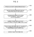
- the computation unit 152 performs the Fourier transform on multiple time-series detection signals in a spatial direction (direction in which the space coordinate extends) and in a time direction (direction in which the time coordinate extends) to obtain a frequency spectrum K f (k x1 , k y1 , ⁇ ) and stores the frequency spectrum K f in the memory unit 153.
- the computation unit 152 performs the Fourier transform on time-series detection signals p d in accordance with Expression 1 to obtain the frequency spectrum K f as frequency signals including a time frequency.
- K f k x ⁇ k y ⁇ ⁇ c 0 2 ⁇ k z ⁇ 1 2 ⁇ ⁇ ⁇ F x , y , t p d x ⁇ y ⁇ t
- k x , k y , and k z denote wave numbers (also called spatial frequencies) (1/m) in the directions of x, y, and z axes, respectively.
- a wave number is a quantity obtained by multiplying a spatial frequency by 2 ⁇ (rad) and expressed in the unit of rad/m.
- the spatial frequency is referred to as a wave number for convenience's sake.
- ⁇ denotes a time frequency (1/s)
- c 0 denotes the sound velocity inside the object
- F x , y , t denotes the Fourier transform.
- acoustic waves are detected by the detection surfaces of the multiple transducers 141 arranged in a (x, y) plane.
- the frequency spectrum obtained by the Fourier transform is expressed as a function of the wave numbers in the x and y axis directions and the time frequency ⁇ .
- the frequency spectrum is obtained as a set of complex numbers obtained when k x , k y , and ⁇ take specific values.
- a complex number corresponding to each combination of k x , k y , and ⁇ is stored in the memory unit 153.
- the numbers of k x and k y are determined on the basis of the number of transducers 141 and the number of time frequency ⁇ is determined on the basis of the number of time-series detection signals sampled in the time direction.
- the upper limits of the numbers of k x and k y and the frequency ⁇ may be changed by interpolation of multiple signals.
- the numbers k x and k y and the frequency ⁇ may be increased or reduced by adding zero (zero padding) to the signals or deleting some signals.
- the computation unit 152 converts the time frequency ⁇ of the frequency spectrum stored in the memory unit 153 in accordance with Expression 2 into a wave number k z in the z axis direction and obtains a wave number spectrum K (k x , k y , k z ) of a frequency signal expressed only by wave numbers.
- the complex numbers of the obtained wave number spectrum (k x , k y , k z ) are stored in the memory unit 153 as measured values.
- k z ⁇ / c 2 - k x 2 - k y 2
- a spectrum including the time frequency is referred to as a frequency spectrum and the spectrum obtained after converting the time frequency into a wave number is referred to as a wave number spectrum.
- the computation unit 152 may obtain the wave number spectrum on the basis of the time-series detection signals without obtaining the frequency spectrum. In other words, the computation unit 152 may obtain the wave number spectrum on the basis of the time-series detection signals using an expression obtained by substituting Expression 2 into Expression 1.
- the Fourier transform in this step may be performed by the fast Fourier transform for reduction of calculations.
- a combination (k x , k y , and k z ) of the spatial frequencies is simply referred to as a "wave number".
- signals in a frequency space are collectively referred to as a frequency signal.
- the computation unit obtains the frequency spectrum or the wave number spectrum, as the first frequency signal, based on the multiple time-series detection signals.
- the computation unit 152 performs correction of phase modulation of acoustic waves on the wave number spectrum stored in the memory unit 153, the phase modulation being attributable to refraction of the acoustic waves at the holding member 130. That is, the computation unit 152 obtains a second frequency signal in which phase modulation is corrected.
- the wave number k d (k dx , k dy , k dz ) is a wave number of acoustic waves that have propagated through the holding member 130 and detected by the multiple transducers 141.
- the origin O may be determined at any position on the acoustic-wave detection surface (x, y).
- acoustic waves are refracted at the interface between the object 100 and the holding member 130.
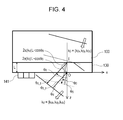
- Fig. 4 illustrates propagation of the acoustic waves with an illustration of the peak of the amplitude of the acoustic waves.
- solid lines indicate the state where acoustic waves that have occurred in the object 100 are refracted and propagate through the holding member 130.
- dotted lines indicate the state where hypothetic acoustic waves that are not refracted propagate.
- ⁇ 0 denotes an incidence angle of the acoustic waves that enter the holding member 130 from the object 100
- ⁇ d denotes a refraction angle of the acoustic waves that have been refracted at the interface between the object 100 and the holding member 130.
- the computation unit 152 obtains the incidence angle ⁇ 0 and the refraction angle ⁇ d .
- ⁇ d is uniquely determined.
- ⁇ 0 is uniquely determined on the basis of ⁇ d , the sound velocity c 0 inside the object 100, and the sound velocity c 1 inside the holding member 130.
- ⁇ d and ⁇ 0 corresponding to the wave number k d are uniquely determined.
- the computation unit 152 can calculate the incidence angle ⁇ 0 and the refraction angle ⁇ d in accordance with the Snell's law on the basis of the wave number k d , the sound velocity c 0 inside the object 100, and the sound velocity c 1 inside the holding member 130.
- the computation unit 152 may select an incidence angle ⁇ 0 and a refraction angle ⁇ d corresponding to the wave number k d from the memory unit 153 in which incidence angles ⁇ 0 and refraction angles ⁇ d corresponding to multiple wave numbers are stored.
- incidence angles ⁇ 0 and refraction angles ⁇ d corresponding to various sound velocities c 0 inside the object 100 and various sound velocities c 1 inside the holding member 130 may be stored in the memory unit 153.
- the computation unit 152 selects the corresponding incidence angle ⁇ 0 and the corresponding refraction angle ⁇ d on the basis of the sound velocity c 0 inside the object 100 and the sound velocity c 1 inside the holding member 130.
- the computation unit 152 obtains, on the basis of the phase ⁇ d of the acoustic waves corresponding to the wave number k d , the phase ⁇ 0 of the acoustic waves corresponding to the wave number k 0 in the case where the acoustic waves are not refracted.
- each of the phase ⁇ d and the phase ⁇ 0 is a phase difference between the peak of the acoustic waves and the origin.
- the point at which the interface between the object 100 and the holding member 130 intersects the z axis is taken as an incident point I and the phases corresponding to the wave numbers k 0 and k d from the incident point I to the acoustic wave peaks are taken as ⁇ 0_I and ⁇ d_I , respectively.
- the phases ⁇ 0_I and ⁇ d_I can be expressed by Expression 3 below from the geometrical relationship illustrated in Fig. 4 .
- the phase ⁇ 0 which is a component of the wave number k 0 , is calculated as illustrated in Expression 5.
- the computation unit 152 calculates a complex value K d ' by correcting the phase modulation using a phase difference i ⁇ as a phase factor from the measured value K d .
- ⁇ is a difference between the phases ⁇ 0 and ⁇ d .
- the measured value K d is expressed by Expression 6, where A denotes the amplitude and i ⁇ d denotes the phase factor.
- K d ⁇ A ⁇ e i ⁇ ⁇ 0
- the complex value K d ' in which the phase modulation corresponding to the wave number k d is corrected can be obtained by multiplying the measured value K d corresponding to the wave number k d by the complex number having the phase factor included in Expression 8.
- sgn (k 0z ) is a sign function that takes +1 when k 0z is larger than or equal to zero and that takes -1 when k 0z is negative.
- k 0z positive has been described.
- Expression 8 when sgn(k 0z ) is -1 serves as a phase factor as a result of the same procedure as that described above.
- i ⁇ sgn k 0 ⁇ z ⁇ i k 0 ⁇ L ⁇ cos ⁇ 0 - ncos ⁇ ⁇ d
- the phase factor illustrated in Expression 8 is uniquely determined as a result of determination of the target wave number k d .
- the computation unit 152 can select the phase factor corresponding to any wave number k d from the memory unit 153 in which phase factors corresponding to multiple wave numbers have been stored in advance.
- the computation unit 152 can obtain the wave number spectrum K', in which phase modulation is corrected, as the second frequency signals by performing the above-described correction of phase modulation on measured values of corresponding wave numbers in the wave number spectrum K.
- Complex values corresponding to the wave numbers in the wave number spectrum K' in which the phase modulation is corrected are stored in the memory unit 153.
- phase modulation attributable to the holding member 130 has been described.
- the phase modulation that can be corrected is not limited to the one attributable to the holding member 130.
- the correction of phase modulation according to the embodiment is applicable to the case where the sound velocity distribution exists on the propagation path of the acoustic waves.
- the present invention is applicable to a phase modulation that occurs in the case where an interface exists inside the object 100 between structures in which sound travels at different velocities.
- structural information inside the object 100 has to be grasped before performing step S400 and the distribution of the sound velocity inside the object 100 has to be grasped from the structural information.
- a structural information obtaining unit such as a magnetic resonance imager (MRI), a diffusion optical tomographic apparatus, or an ultrasonic echo apparatus may obtain the structural information inside the object 100 before performing step S400.
- the structural information obtaining unit may be included in the object information obtaining system or provided as a separate unit.
- the structural information inside the object 100 can be obtained while a size increase of the apparatus is minimized.
- the presumed structural information may be used.
- the signal processor 150 may obtain the sound velocity distribution on the basis of the structural information obtained in the above described manner.
- the present invention is also applicable to a phase modulation attributable to a member disposed outside the object 100 other than the holding member 130.
- phase modulation can be corrected by performing the same operations on the layers as those described above.
- S500 Step of Obtaining Object Information on the Basis of Wave Number Spectrum in Which Phase Modulation Has Been Corrected
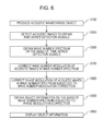
- the computation unit 152 obtains object information on the basis of the corrected wave number spectrum obtained in step S400.
- the computation unit 152 performs the inverse Fourier transform on the wave number spectrum K' obtained in step S400 and in which the phase modulation has been corrected and thus obtains an initial acoustic pressure distribution p 0 (x, y, z) inside the object 100.
- p 0 x ⁇ y ⁇ z F x , y , z - 1 K ⁇
- the initial acoustic pressure distribution is obtained by using the complex value obtained by correcting the phase modulation attributable to the refraction at the holding member 130. Thus, the reduction of the quantitativeness due to the phase modulation is minimized.
- the computation unit 152 may restore time-series detection signals, in which phase modulation is corrected, by performing operations in the order opposite to that of the operations illustrated in Expression 1 and Expression 2 on the wave number spectrum, in which phase modulation is corrected, obtained in step S400.
- the computation unit 152 can obtain an initial acoustic pressure distribution by performing appropriate reconstruction on the time-series detection signals, in which phase modulation is corrected. This method enables obtaining an initial acoustic pressure distribution with the performance of appropriate reconstruction instead of performing the inverse Fourier transform for reconstruction. Examples of appropriate reconstruction include a time-domain back projection method and a model based method.
- the computation unit 152 may obtain an absorption coefficient distribution inside the object 100 on the basis of the obtained initial acoustic pressure distribution and the distribution of light quantity of light projected on the object 100 inside the object 100.
- light beams having multiple different wavelengths may be individually subjected to steps S100 to S500, so that object information corresponding to the multiple wavelengths may be obtained.
- the concentration of materials inside the object may be obtained using the object information corresponding to the multiple wavelengths. Also in various types of object information thus obtained, a reduction of the quantitativeness due to the phase modulation is minimized.
- S600 Step of Displaying Object Information
- an image of the object information obtained in step S500 is displayed on the display unit 160.
- the computation unit 152 performs an operation such as luminance conversion on the object information obtained in step S500 in order that the object information can be displayed on the display unit 160, generates image data corresponding to the object information, and outputs the image data to the display unit 160. Since the object information displayed on the display unit 160 is information in which a reduction of the quantitativeness due to the phase modulation is minimized, the object information is suitably usable by practitioners such as medical doctors for diagnosis.
- the above-described method for obtaining object information according to the embodiment enables obtaining object information in which the phase modulation of acoustic waves attributable to the sound velocity distribution of the holding member or the like is corrected. Thus, a reduction of the quantitativeness of the object information thus obtained can be minimized.
- correction of phase modulation performed by calculating a propagation path of one sound ray corresponding to a plane wave in accordance with the Snell's law can be performed by performing, on frequency signals, correction of phase modulation.
- the method for correcting the phase modulation according to the embodiment involves fewer calculations.
- the second embodiment describes the case where the interface between materials in which sound travels at different velocities is inclined at an angle ⁇ with respect to the acoustic-wave detection surface.
- the second embodiment describes the case where the detection surfaces of the multiple transducers 141 and the interface between the object 100 and the holding member 130 are disposed at an angle ⁇ around the y axis.
- the angle ⁇ is an angle formed by the detection surfaces of the multiple transducers 141 and one surface of the holding member 130.
- the wave number in the direction parallel to the interface is conserved.
- the wave numbers in the x and y axis directions of the wave number k 0 are respectively the same as the wave numbers in the x and y axis directions of the wave number k d since the interface between the object 100 and the holding member 130 is parallel to the acoustic-wave detection surface (x-y plane).
- the wave number in the x axis direction in front of or behind the interface is not conserved.
- the wave number in the x' direction that is parallel to the interface is conserved.
- the wave number in the x axis direction of the wave number k0 is different from the wave number in the x axis direction of the wave number kd.
- step S400 if the correction of the phase modulation described in step S400 is performed assuming that the wave number in the x axis direction of acoustic waves before the acoustic waves propagate through the holding member 130 is kdx, which is supposed to be k0x, the effect of minimizing the reduction of the quantitativeness of the object information becomes insufficient.
- correction of wave number modulation of acoustic waves attributable to the inclination of the interface between materials in which sound travels at different velocities is performed on the wave number spectrum before performing the correction of phase modulation of acoustic waves.
- the wave number in the x axis direction in front of or behind the interface is not conserved.
- the wave number of a component that is parallel to the interface (here, the x' axis direction) in front of or behind the interface is conserved.
- the wave number in the y axis direction in front of or behind the interface is conserved.
- the computation unit 152 obtains the wave number k 0 (k 0x and k 0z ) from the wave number k d (k dx and k dz ) on the basis of Expression 10, which is derived from the affine transformation and the Snell's law.
- the computation unit 152 then stores the measured value K d , which has been stored in an address corresponding to the wave number k d , in an address corresponding to the wave number k 0 calculated through Expression 10.
- ⁇ d ' is calculated by adding the refraction angle ⁇ d and the angle ⁇ .
- the refraction angle ⁇ d is uniquely determined from the wave number k d .
- the computation unit 152 can calculate the wave number k 0 on the basis of information of the angle ⁇ formed by the detection surfaces of the multiple transducers 141 and the holding member 130.
- the angle ⁇ may be obtained from images such as an image that can be taken by a measurement unit such as a charge coupled device (CCD).
- CCD charge coupled device
- the method for correcting the wave number modulation is not limited to the above method as long as the method enables obtaining the wave number k 0 in the coordinate system of the interface between materials in which sound travels at different velocities from the wave number k d in the coordinate system of the detection surface.
- the computation unit 152 firstly obtains, through the affine transformation, the wave number k d in the coordinate system (x', y', z') at the interface between the object 100 and the holding member 130 from the wave number k d in the coordinate system on the detection surface and stores the wave number k d in the coordinate system (x', y', z') at the interface in the memory unit 153.
- the computation unit 152 obtains, through the Snell's law, the wave number k 0 in the coordinate system at the interface from the wave number k d in the coordinate system at the interface stored in the memory unit 153 and stores the wave number k 0 in the memory unit 153.
- the computation unit 152 obtains, through the affine transformation, the wave number k 0 in the coordinate system on the detection surface from the wave number k 0 in the coordinate system at the interface stored in the memory unit 153 and stores the wave number k 0 in the coordinate system on the detection surface in the memory unit 153.
- the wave number k 0 in the coordinate system on the detection surface may be obtained from the wave number k d in the coordinate system on the detection surface in this manner.
- the wave number spectrum in which the wave number modulation has been corrected can be obtained by performing the above-described processing on each wave number in the wave number spectrum.
- the measured value K d may be obtained from the multiple time-series detection signals stored in the memory unit 153 and may be directly stored to the address corresponding to the wave number k 0 .
- correction of phase modulation may be performed using the measured value K d as a measured value corresponding to the wave number k 0 in step S800, described below, without obtaining the wave number spectrum, in which wave number modulation is corrected.
- such a case can be also regarded as the case involving the correction of the wave number modulation.
- correctable wave number modulation is not limited to the one attributable to the inclination of the holding member 130 in this embodiment.
- the correction of the wave number modulation according to the embodiment is applicable to the case where an interface between two layers in which sound travels at different velocities is disposed at a certain angle with the acoustic-wave detection surface in the propagation path of the acoustic waves.
- the wave number modulation can be corrected by performing the same processing on each layer.
- This embodiment describes the case where there is no inclination in the y axis direction.
- the wave number modulation can be easily corrected by extending Expression 10, which is a two-dimensional affine transformation, to a typical three-dimensional affine transformation.
- the affine transformation is used for transformation of the coordinate system but another rotational transform may also be used.
- Euler transform or other types of transformation may be used.
- step S800 correction of phase modulation is performed on the wave number spectrum obtained in step S700 and in which the wave number modulation has been corrected.
- Step S800 corresponds to step S400 according to the first embodiment. Also in step S800, performing the same correction as that performed in step S400 enables the correction of the wave number modulation and the phase modulation of acoustic waves attributable to the interface between two layers in which sound travels at different velocities. Thus, the quantitativeness of object information obtainable in the subsequent step of Step S500 can be improved.
- correction of phase modulation may be performed using, for example, the measured value K d corresponding to the wave number k d obtained in step S300 as a measured value corresponding to the wave number k 0 .
- This method also enables the correction of the wave number modulation and the phase modulation of acoustic waves attributable to the interface between two layers in which sound travels at different velocities.
- the method for obtaining object information according to the embodiment enables obtaining object information in which wave number modulation has been corrected in addition to the phase modulation of acoustic waves attributable to the sound velocity distribution in the holding member or the like.
- a reduction of an obtainable quantitativeness of object information can be minimized.
- a physical quantity not affixed with a unit represents that the physical quantity is standardized with an appropriate constant.
- the origin of coordinates is defined at one vertex of a calculation space and each side of the calculation space has a coordinate extending from zero to a positive maximum value.
- the following four pieces of measurement data are calculated through the simulation.
- the calculation space is a three-dimensional space having a width (x) of 120 mm, a length (y) of 46 mm, and a height (z) of 60 mm.
- the three-dimensional space was divided into cubic cells each having sides of 0.5 mm.
- Nine wire-shaped digital phantoms having a diameter of 1 mm, a length of 46 mm, and a fixed inner pressure of 1 are disposed in the calculation space at intervals of 5 mm in width and at intervals of 5 mm in height.
- the first region had a density of 1 and a modulus of elasticity of 1 and the second region had a density of 0.833 and a modulus of elasticity of 1.8.
- Second measurement data pieces are calculated in the following manner.
- the calculation space is a two-dimensional space having a width (x) of 30 mm and a length (y) of 60 mm.
- the two-dimensional space was divided into square cells each having sides of 50 ⁇ m.
- the pressure distribution at arbitrary time was calculated by the general acoustic finite-difference time domain (FDTD) method using an initial pressure distribution inside the calculation space obtained in the above-described method as an initial value.
- FDTD general acoustic finite-difference time domain
- the acoustic characteristics inside the calculation space were divided into three regions by two interfaces parallel to the x axis.
- the acoustic characteristics in each region were defined as follows.
- the first region had a density of 1 and a modulus of elasticity of 1
- the second region had a density of 0.833 and a modulus of elasticity of 1.8
- the third region had a density of 0.91 and a modulus of elasticity of 0.9.
- the line was divided into sections each having a length of 45 ⁇ m.
- the pressure distribution evaluated at the center of each section was chronologically recorded and the obtained results were second measurement data pieces.
- Third measurement data pieces are calculated in the following manner. All the conditions were the same as those set to obtain the second measurement data pieces except for the probe.
- the line was divided into sections each having a length of 45 ⁇ m.
- the pressure distribution evaluated at the center of each section was chronologically recorded and the obtained results were third measurement data pieces.
- the third measurement data pieces are different from the second measurement data pieces in terms that the interferences that separate regions having different acoustic characteristics from each other are not parallel to the detection surface.
- Fourth measurement data pieces are calculated in the following manner. All the conditions were the same as those set to obtain the second measurement data pieces except for the distribution of the acoustic characteristics.
- the first arc had a diameter of 100 mm and the second arc had a diameter of 110 mm.
- the divided regions were referred to as the same names as those in the case of the second measurement data pieces and the acoustic characteristics in each region were defined in the same manner as in the case of the second measurement data pieces.
- the fourth measurement data pieces are different from the second measurement data pieces in terms that the interfaces that separate regions having different acoustic characteristics from each other are arcs having large radii of curvature.
- the detection surface is parallel to the interfaces between regions in which sound travels at different velocities.
- the correction of the wave number modulation described in the second embodiment is not performed.
- Fig. 7 illustrates signals obtained after performing correction of phase modulation on the second measurement data pieces (signals after correction), the second measurement data pieces (signals before correction), and signals obtained in the case where the sound velocity is uniform (true value signals).
- the signals after the correction of phase modulation are time-series signals of actual time obtained by performing the inverse Fourier transform on the wave number spectrum, the correction of phase modulation being performed on the second measurement data pieces in the wave number spectrum and the wave number spectrum being obtained by performing steps S300 and S400 according to the first embodiment.
- these signals represent values measured at the center of the probe.
- the vertical axis represents the pressure and the horizontal axis represents the standardized time.
- Fig. 8A illustrates an initial acoustic pressure distribution reconstructed without performing correction of phase modulation on the first measurement data pieces
- Fig. 8B illustrates an initial acoustic pressure distribution reconstructed after performing correction of phase modulation on the first measurement data pieces.
- Fig. 8B illustrates results obtained by reconstructing, through the k-space method, the wave number spectrum obtained by performing steps S300 and S400 according to the first embodiment and in which correction of phase modulation is performed on the first measurement data pieces, the k-space method being exemplified in Journal of Biomedical Optics 15 (2), 021314 (March/April 2010 )) .
- the time taken to calculate the distribution illustrated in Fig. 8B was 3.7 seconds including the time required for performing the reconstruction using the k-space method and the time required for inputting and outputting data under the environment of the calculator of 1.4 GFLOPS.
- the time taken to perform the reconstruction using the k-space method without performing the correction was 3.1 seconds.
- the difference resulting from subtraction, 0.6 seconds was the time taken to perform the correction of phase modulation.
- the correction method according to the embodiment enables reduction of time taken for the correction of phase modulation compared to the correction method according to an existing technology.
- the correction method according to the embodiment involves fewer calculations than in the case of the existing correction method.
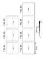
- Figs. 9A to 9G illustrate results of reconstruction after performing the correction of phase modulation on the second measurement data pieces and performing the correction of phase modulation and the correction of the wave number modulation on the third and fourth measurement data pieces.
- the reconstruction in the calculation illustrated in Fig. 9 was performed by the back projection method.
- Figs. 9A, 9B, and 9C on the upper part illustrate the results of reconstruction of the second, third, and fourth measurement data pieces without the correction.
- Figs. 9D, 9E, and 9F on the lower part illustrate the results of reconstruction of the second, third, and fourth measurement data pieces after the correction.
- Fig. 9G on the lower part illustrates the result of reconstruction in the case where the sound velocity is uniform (while the conditions of the probe are similar to the case of the second measurement data pieces).
- the examples show that the method for obtaining object information according to the present invention enables obtaining object information in which, not only phase modulation of acoustic waves attributable to the sound velocity distribution, but also the wave number modulation is corrected.
- the examples also show that the correction can be performed with fewer calculations than in the case of an existing method.
Landscapes
- Health & Medical Sciences (AREA)
- Life Sciences & Earth Sciences (AREA)
- Engineering & Computer Science (AREA)
- Physics & Mathematics (AREA)
- Animal Behavior & Ethology (AREA)
- Veterinary Medicine (AREA)
- Biophysics (AREA)
- Pathology (AREA)
- Public Health (AREA)
- Biomedical Technology (AREA)
- Heart & Thoracic Surgery (AREA)
- Medical Informatics (AREA)
- Molecular Biology (AREA)
- Surgery (AREA)
- General Health & Medical Sciences (AREA)
- Radiology & Medical Imaging (AREA)
- Nuclear Medicine, Radiotherapy & Molecular Imaging (AREA)
- Computer Vision & Pattern Recognition (AREA)
- Acoustics & Sound (AREA)
- Signal Processing (AREA)
- Artificial Intelligence (AREA)
- Psychiatry (AREA)
- Physiology (AREA)
- Computer Networks & Wireless Communication (AREA)
- Remote Sensing (AREA)
- Radar, Positioning & Navigation (AREA)
- General Physics & Mathematics (AREA)
- Ultra Sonic Daignosis Equipment (AREA)
- Investigating Or Analyzing Materials By The Use Of Ultrasonic Waves (AREA)
Applications Claiming Priority (1)
| Application Number | Priority Date | Filing Date | Title |
|---|---|---|---|
| JP2013133533 | 2013-06-26 |
Publications (1)
| Publication Number | Publication Date |
|---|---|
| EP2818117A1 true EP2818117A1 (en) | 2014-12-31 |
Family
ID=51032914
Family Applications (1)
| Application Number | Title | Priority Date | Filing Date |
|---|---|---|---|
| EP14171887.4A Withdrawn EP2818117A1 (en) | 2013-06-26 | 2014-06-11 | Object information obtaining system, signal processing method, and program |
Country Status (4)
| Country | Link |
|---|---|
| US (1) | US10264979B2 (enExample) |
| EP (1) | EP2818117A1 (enExample) |
| JP (1) | JP6425428B2 (enExample) |
| CN (1) | CN104248452B (enExample) |
Cited By (1)
| Publication number | Priority date | Publication date | Assignee | Title |
|---|---|---|---|---|
| JP2018057560A (ja) * | 2016-10-04 | 2018-04-12 | コニカミノルタ株式会社 | 超音波信号処理装置、超音波信号処理方法、及び、超音波診断装置 |
Families Citing this family (2)
| Publication number | Priority date | Publication date | Assignee | Title |
|---|---|---|---|---|
| US20200315574A1 (en) * | 2016-06-24 | 2020-10-08 | Canon Kabushiki Kaisha | Apparatus and information processing method |
| JP2018061716A (ja) * | 2016-10-13 | 2018-04-19 | キヤノン株式会社 | 情報処理装置、情報処理方法、及びプログラム |
Citations (3)
| Publication number | Priority date | Publication date | Assignee | Title |
|---|---|---|---|---|
| US20040006272A1 (en) * | 2002-07-08 | 2004-01-08 | Insightec - Image Guided Treatment, Ltd. | Tissue inhomogeneity correction in ultrasound imaging |
| JP2010167258A (ja) | 2008-12-25 | 2010-08-05 | Canon Inc | 生体情報取得装置 |
| EP2287632A1 (en) * | 2004-07-23 | 2011-02-23 | Bjorn A. J. Angelsen | Ultrasound imaging using non-linear manipulation of forward propagation properties of a pulse |
Family Cites Families (22)
| Publication number | Priority date | Publication date | Assignee | Title |
|---|---|---|---|---|
| US4594662A (en) * | 1982-11-12 | 1986-06-10 | Schlumberger Technology Corporation | Diffraction tomography systems and methods with fixed detector arrays |
| US4549289A (en) * | 1983-06-20 | 1985-10-22 | Jack Schwartz | Method for correcting acoustic distortion |
| US4640132A (en) * | 1985-01-15 | 1987-02-03 | The Babcock & Wilcox Company | Enhancement of linear scan ultrasonics |
| JPH0563509U (ja) | 1992-02-07 | 1993-08-24 | 横河メディカルシステム株式会社 | 受波ディジタルビームフォーマ |
| JPH0670928A (ja) * | 1992-08-26 | 1994-03-15 | Yokogawa Medical Syst Ltd | 超音波診断装置の遅延時間補正方法および超音波診断装置 |
| JP3728756B2 (ja) * | 1992-10-13 | 2005-12-21 | 富士通株式会社 | 離散フーリエ変換値の遅延時間補正装置 |
| JP3320853B2 (ja) * | 1993-09-09 | 2002-09-03 | フクダ電子株式会社 | 超音波診断装置 |
| US5675550A (en) | 1995-06-08 | 1997-10-07 | Ekhaus; Ira B. | Reduced wavenumber synthetic aperture |
| JP3502700B2 (ja) * | 1995-08-17 | 2004-03-02 | ジーイー横河メディカルシステム株式会社 | 超音波診断画像形成装置 |
| JP3492095B2 (ja) * | 1996-07-22 | 2004-02-03 | ジーイー横河メディカルシステム株式会社 | 超音波撮像装置 |
| US5935068A (en) * | 1996-11-01 | 1999-08-10 | The Trustees Of The University Of Pennsylvania | System and method for improving ultrasound image contrast by amplitude compression of ultrasonic wavefront signals |
| JP3321068B2 (ja) | 1998-02-05 | 2002-09-03 | 松下電器産業株式会社 | 超音波診断装置 |
| JP2000254121A (ja) * | 1999-03-12 | 2000-09-19 | Ge Yokogawa Medical Systems Ltd | 受信信号形成方法および装置並びに超音波撮像方法および装置 |
| WO2001057514A1 (en) * | 2000-01-31 | 2001-08-09 | Angelsen Bjoern A J | Correction of phasefront aberrations and pulse reverberations in medical ultrasound imaging |
| AU2003242971A1 (en) * | 2002-07-15 | 2004-02-02 | Ariel Ltd. | Method and apparatus for imaging through scattering or obstructing media |
| WO2006041058A1 (ja) | 2004-10-15 | 2006-04-20 | Hitachi Medical Corporation | 超音波診断装置 |
| FR2920214B1 (fr) * | 2007-08-20 | 2009-10-02 | Aircelle Sa | Joint d'etancheite double |
| JP5349115B2 (ja) | 2009-03-31 | 2013-11-20 | 株式会社東芝 | 超音波診断装置及びその制御プログラム |
| TWI401864B (zh) * | 2009-07-29 | 2013-07-11 | Joy Ride Tech Co Ltd | A motor with internal thermal glue |
| JP5419727B2 (ja) * | 2010-01-22 | 2014-02-19 | キヤノン株式会社 | 画像形成方法及び音響波測定装置 |
| JP5645421B2 (ja) | 2010-02-23 | 2014-12-24 | キヤノン株式会社 | 超音波画像装置および遅延制御方法 |
| JP2011179896A (ja) * | 2010-02-26 | 2011-09-15 | Nec Corp | ビーム合成装置、ビーム合成方法及び円筒アレイ受信システム |
-
2014
- 2014-06-11 EP EP14171887.4A patent/EP2818117A1/en not_active Withdrawn
- 2014-06-23 JP JP2014128620A patent/JP6425428B2/ja not_active Expired - Fee Related
- 2014-06-23 US US14/311,613 patent/US10264979B2/en not_active Expired - Fee Related
- 2014-06-26 CN CN201410293293.7A patent/CN104248452B/zh not_active Expired - Fee Related
Patent Citations (4)
| Publication number | Priority date | Publication date | Assignee | Title |
|---|---|---|---|---|
| US20040006272A1 (en) * | 2002-07-08 | 2004-01-08 | Insightec - Image Guided Treatment, Ltd. | Tissue inhomogeneity correction in ultrasound imaging |
| EP2287632A1 (en) * | 2004-07-23 | 2011-02-23 | Bjorn A. J. Angelsen | Ultrasound imaging using non-linear manipulation of forward propagation properties of a pulse |
| JP2010167258A (ja) | 2008-12-25 | 2010-08-05 | Canon Inc | 生体情報取得装置 |
| US20110251475A1 (en) * | 2008-12-25 | 2011-10-13 | Canon Kabushiki Kaisha | Biological information acquisition apparatus and biological information acquisition method |
Non-Patent Citations (2)
| Title |
|---|
| JOURNAL OF BIOMEDICAL OPTICS, vol. 15, no. 2, March 2010 (2010-03-01), pages 021314 |
| PAI-CHI LI ET AL: "Adaptive imaging using the generalized coherence factor", IEEE TRANSACTIONS ON ULTRASONICS, FERROELECTRICS AND FREQUENCY CONTROL, IEEE, US, vol. 50, no. 2, 2 February 2003 (2003-02-02), pages 128 - 141, XP011368416, ISSN: 0885-3010, DOI: 10.1109/TUFFC.2003.1182117 * |
Cited By (1)
| Publication number | Priority date | Publication date | Assignee | Title |
|---|---|---|---|---|
| JP2018057560A (ja) * | 2016-10-04 | 2018-04-12 | コニカミノルタ株式会社 | 超音波信号処理装置、超音波信号処理方法、及び、超音波診断装置 |
Also Published As
| Publication number | Publication date |
|---|---|
| JP6425428B2 (ja) | 2018-11-21 |
| JP2015027445A (ja) | 2015-02-12 |
| US10264979B2 (en) | 2019-04-23 |
| US20150005611A1 (en) | 2015-01-01 |
| CN104248452A (zh) | 2014-12-31 |
| CN104248452B (zh) | 2016-12-07 |
Similar Documents
| Publication | Publication Date | Title |
|---|---|---|
| US10136821B2 (en) | Image generating apparatus, image generating method, and program | |
| KR101483502B1 (ko) | 피검체 정보 취득장치, 피검체 정보 취득방법 및 기억매체 | |
| JP5441781B2 (ja) | 光音響イメージング装置、光音響イメージング方法及びプログラム | |
| EP3427645B1 (en) | Display data obtaining apparatus and display data obtaining method | |
| EP2482713B1 (en) | Photoacoustic measuring apparatus | |
| CN103025248B (zh) | 图像信息获取装置和图像信息获取方法 | |
| JP2011005042A (ja) | 光音響イメージング装置及び光音響イメージング方法 | |
| EP3192435A2 (en) | Information acquisition apparatus, signal processing method, and program | |
| JP6289050B2 (ja) | 被検体情報取得装置、情報処理方法、およびプログラム | |
| US20170281125A1 (en) | Processing system, signal processing method, and non-transitory storage medium | |
| EP2818117A1 (en) | Object information obtaining system, signal processing method, and program | |
| JP2017140092A (ja) | 被検体情報取得装置 | |
| WO2013183247A1 (ja) | 音響光学撮像装置 | |
| JP6701005B2 (ja) | 装置および情報処理方法 | |
| JP6469133B2 (ja) | 処理装置、光音響装置、処理方法、およびプログラム | |
| JP5424846B2 (ja) | 光音響イメージング装置 | |
| JP2017131560A (ja) | 超音波装置 | |
| JP6614968B2 (ja) | 情報処理装置、被検体情報取得装置、情報処理方法、及びプログラム | |
| JP2017202149A (ja) | 装置、方法、及びプログラム |
Legal Events
| Date | Code | Title | Description |
|---|---|---|---|
| PUAI | Public reference made under article 153(3) epc to a published international application that has entered the european phase |
Free format text: ORIGINAL CODE: 0009012 |
|
| 17P | Request for examination filed |
Effective date: 20140611 |
|
| AK | Designated contracting states |
Kind code of ref document: A1 Designated state(s): AL AT BE BG CH CY CZ DE DK EE ES FI FR GB GR HR HU IE IS IT LI LT LU LV MC MK MT NL NO PL PT RO RS SE SI SK SM TR |
|
| AX | Request for extension of the european patent |
Extension state: BA ME |
|
| R17P | Request for examination filed (corrected) |
Effective date: 20150630 |
|
| RBV | Designated contracting states (corrected) |
Designated state(s): AL AT BE BG CH CY CZ DE DK EE ES FI FR GB GR HR HU IE IS IT LI LT LU LV MC MK MT NL NO PL PT RO RS SE SI SK SM TR |
|
| STAA | Information on the status of an ep patent application or granted ep patent |
Free format text: STATUS: EXAMINATION IS IN PROGRESS |
|
| 17Q | First examination report despatched |
Effective date: 20170410 |
|
| STAA | Information on the status of an ep patent application or granted ep patent |
Free format text: STATUS: THE APPLICATION HAS BEEN WITHDRAWN |
|
| 18W | Application withdrawn |
Effective date: 20210910 |