EP2816231B2 - Gerät zum Spülen und/oder zur Druck- und Dichtheitsprüfung von Leitungen, insbesondere von Trinkwasser- und/oder Heizungssystemen - Google Patents
Gerät zum Spülen und/oder zur Druck- und Dichtheitsprüfung von Leitungen, insbesondere von Trinkwasser- und/oder Heizungssystemen Download PDFInfo
- Publication number
- EP2816231B2 EP2816231B2 EP14001893.8A EP14001893A EP2816231B2 EP 2816231 B2 EP2816231 B2 EP 2816231B2 EP 14001893 A EP14001893 A EP 14001893A EP 2816231 B2 EP2816231 B2 EP 2816231B2
- Authority
- EP
- European Patent Office
- Prior art keywords
- compressed air
- pressure
- water
- valve
- line
- Prior art date
- Legal status (The legal status is an assumption and is not a legal conclusion. Google has not performed a legal analysis and makes no representation as to the accuracy of the status listed.)
- Active
Links
Images
Classifications
-
- F—MECHANICAL ENGINEERING; LIGHTING; HEATING; WEAPONS; BLASTING
- F04—POSITIVE - DISPLACEMENT MACHINES FOR LIQUIDS; PUMPS FOR LIQUIDS OR ELASTIC FLUIDS
- F04B—POSITIVE-DISPLACEMENT MACHINES FOR LIQUIDS; PUMPS
- F04B35/00—Piston pumps specially adapted for elastic fluids and characterised by the driving means to their working members, or by combination with, or adaptation to, specific driving engines or motors, not otherwise provided for
- F04B35/06—Mobile combinations
-
- F—MECHANICAL ENGINEERING; LIGHTING; HEATING; WEAPONS; BLASTING
- F04—POSITIVE - DISPLACEMENT MACHINES FOR LIQUIDS; PUMPS FOR LIQUIDS OR ELASTIC FLUIDS
- F04B—POSITIVE-DISPLACEMENT MACHINES FOR LIQUIDS; PUMPS
- F04B41/00—Pumping installations or systems specially adapted for elastic fluids
- F04B41/02—Pumping installations or systems specially adapted for elastic fluids having reservoirs
Definitions
- the invention relates to a device for flushing and for testing the pressure and tightness of pipes in drinking water and/or heating systems.
- Analogue and digital pressure testers are known with which lines can be tested for pressure and tightness.
- the devices are equipped with hand pumps with which a certain pressure can be applied.
- the regulations prescribe ever higher pressures for the pressure and leak test.
- such pressures can no longer be generated with hand pumps.
- it is necessary to use electric pumps in addition to the devices which not only require an additional, expensive device, but also complicate the testing process due to the cumbersome handling.
- the pamphlet CA-A1-2 639 600 discloses a device for checking valves, the device having a line with a water connection, an air connection and an outlet for connection to the valves to be checked. There is a valve in each of the water connection and the air connection.
- the invention is based on the object of designing the generic device in such a way that it can be used to carry out the required flushing in a cost-effective and simple manner and/or tests of the piping systems can be carried out.
- the device preferably has at least one pressure generator, which is arranged on the base frame and can apply the high pressure required for the test according to EN 806-4.
- the device is equipped with a compressor and/or a pump for this purpose.
- the required test pressure can be generated with these pressure generators. Therefore, no additional devices are required in addition to the device according to the invention. The craftsman can therefore easily carry out the necessary tests of the line systems.
- the pressure generator can be used for the pressure test with air or for the pressure test with water.
- the device has at least one water line which is provided with a connection for the water network and with an outlet to which a hose can be connected, for example, which connects the device to the line system to be tested.
- At least one compressed air line via which compressed air can be supplied, opens into the water line. This makes it possible to introduce a water-compressed air mixture into the line system. This procedure is used when flushing the pipe systems. Since the switching valve is located in the compressed air line, access of the compressed air to the water line can be released or blocked as required. It is therefore possible with the device to flush the lines either with water alone or with a mixture of water and compressed air.
- the switching valve is advantageously a 3/2-way valve.
- the compressed air can be supplied continuously or else in pulses.
- the user of the device according to the invention has the option, depending on the existing conditions to select the most favorable flushing method with and without compressed air, whereby the compressed air can also be supplied continuously or in pulses.
- At least one compressor is located in the compressed air line, with which the compressed air pressure required for the respective application can be easily generated.
- At least one compressed air tank is advantageously connected downstream of the compressor. This ensures that a sufficient amount of compressed air is available as soon as the device is switched on. With the compressor, the compressed air tank can be refilled with compressed air in a simple manner.
- Another compressed air line is connected to the switching valve. It is provided with a connection to which the line system to be tested can be connected with a hose or similar. A pressure test with compressed air is therefore possible via this connection. In the other compressed air line sits another switching valve with which the other compressed air line can be opened or blocked, depending on the test to be carried out by the user of the device.
- the further switching valve advantageously forms a changeover switch for a pressure test with air or with liquid, preferably with water. Depending on the switching position of this additional switching valve, the user of the device can select the medium required for the test.
- the further switching valve is preferably a 3/2-way valve.
- an air supply line is connected to the further switching valve, which in turn connects this further switching valve to a pressure generator for the liquid medium.
- the device can thus be switch from a pressure test with air to a pressure test with liquid, especially water.
- the compressed air tank is formed by a base frame of the base frame of the device according to the invention.
- the base frame is correspondingly hollow and pressure-tight. A separate container to be attached to the base frame, which would require additional installation space, is therefore not required as a compressed air container.
- the base frame is already provided on the device, so that no additional installation space is required. As a result, the device according to the invention can be made very compact.
- the base frame is advantageously mirror-symmetrical to the longitudinal center plane of the base frame.
- This design of the base frame enables the various components of the device to be mounted in a space-saving manner and contributes to a compact design.
- this design allows the center of gravity of the device to be set favorably.
- the base frame has two U-shaped frame parts which are arranged upright and merge into one another by two horizontal frame parts.
- the U-shaped frame parts are advantageously provided opposite one another on the device.
- the legs of these frame parts advantageously extend downwards, so that the horizontal frame parts are arranged in the lower area of the device.
- This training contributes to a favorable low center of gravity of the device, making the handling of the device is much easier.
- the base frame with the frame parts can be produced very easily because tubes can be used as the starting material, which can be easily bent into the desired shape and then connected to one another in a pressure-tight manner in a suitable manner, for example by a welding process.
- the U-shaped frame parts are advantageously bent in such a way that they have a part of the horizontal frame parts.
- the horizontal frame parts of the two U-shaped frame parts are welded together, resulting in the base frame.
- a floor is advantageously fastened to the horizontal frame parts of the base frame.
- the various components and units of the device can be mounted on it.
- the base frame thus not only has the function of a compressed air tank, but also serves as a supporting frame with which the components mounted on the floor and/or on the base frame are carried.
- a standing partition wall is arranged on the floor.
- the partition wall can be designed in such a way that it optimally shields the components on one side and on the other side from one another, so that these components cannot influence one another.
- the dividing wall can be designed as a heat protection wall, which ensures that the heat generated by individual units during operation of the device is dissipated in such a way that other components are not affected by the heat.
- the device can be constructed in such a way that the heat-insensitive components are located on one side of the partition wall, while the heat-generating components, such as the compressor or the pump, are arranged on the other side.
- the partition wall is also suitable as a mounting wall to which the components of the device can be attached.
- the switching valves are advantageously connected to a controller. With the control, the switching valves can be switched by the operator to the desired extent.
- the device is advantageously provided with at least one control panel with input elements for input of data and/or commands into the controller.
- the user can make the necessary entries for the respective application on the control panel. For example, he can set the device for a flushing process or for a pressure and leak test.
- the device can also have a connection for an air-powered tool.
- This connection is advantageously connected to the compressed air tank.
- the user of the device has the option not only of flushing or checking the line systems, but also of carrying out any installation work associated with the laying of lines using appropriate tools operated by compressed air.
- the device according to the invention enables the user to carry out a wide variety of functions, for which only the single device is necessary and additional devices are not required.
- the device gives the user the ability to perform the eight functions listed above without requiring additional devices.
- the device can also be equipped in such a way that only function 5 or function 8 or both functions 5 and 8 can be performed with it. It is also possible to equip the device in such a way that it can perform functions 1 to 7. In the maximum configuration, the device can perform all functions 1 to 8.
- the device has a base frame 1 ( 3 ), which has two parallel frame parts 2, 3.
- the two frame parts 2, 3 go at both ends curved in an arc in upward frame parts 4, 5; 6, 7 over.
- the frame parts 4 to 7 run parallel to one another and perpendicular to the two lower frame parts 2, 3.
- the frame parts 4, 6 curve into a frame part 8 and the frame parts 5, 7 curve into a frame part 9.
- the two frame parts 8, 9 are parallel to each other and advantageously at the same height.
- the base frame 1 is formed on the two long sides of the device by the U-shaped mutually lying frame parts 2, 4, 5 and 3, 6, 7, which are connected to each other by the upper frame part 9, 8.
- These U-shaped frame areas are characterized in that the frame parts 4, 5 and 6, 7 run upwards from the lower frame part 2, 3.
- the base frame 1 is formed by the frame parts 4, 6, 8 and 5, 7, 9 arranged in a U-shape, the frame parts 4, 6 and 5, 7 extending downwards from the upper frame part 8, 9 extend.
- the U-shaped frame parts are made from two tubes. They are bent in such a way that the U-shaped frame parts 4, 6, 8 and 5, 7, 9 still have part of the horizontal frame parts 2, 3.
- the frame parts bent in this way are placed together with the horizontal sections and welded together in a pressure-tight manner.
- the horizontal sections form the frame parts 2, 3 of the base frame 1.
- the weld which is advantageously located halfway along the frame parts 2, 3, is in 3 indicated by a dashed line.
- the device Due to the design of the base frame 1 described, the device has a high rigidity.
- a partition 11 which is vertical extends to the floor 10 and is fixed on it.
- the partition wall 11 is also advantageously formed by a plate which, in the exemplary embodiment, has a rectangular outline and extends over the entire length of the floor 10 .
- the upward narrow sides 12, 13 of the partition 11 are each angled.
- the narrow side 12 is angled in a U-shape.
- the opposite narrow side 13 is only bent at right angles.
- the shape of these narrow sides 12, 13 depends on those units that are to be mounted on the floor 10 and/or on the partition wall 11.
- the two frame parts 4, 6 are connected to one another by a cross brace 14, which is located at a small distance below the frame part 8.
- the opposite vertical frame parts 5, 7 are connected to one another at a small distance below the frame part 9 by a cross brace 15.
- the two crossbars 14, 15 are at the same height, but can also be provided at different heights, depending on the design of the device.
- the partition wall 11 can vary in height depending on the structure of the device. In the illustrated embodiment, the upper edge of the partition wall 11 is at a distance in the area below the cross braces 14, 15, viewed in the longitudinal direction of the frame parts 2, 3.
- the base frame 1 not only has a support and carrying function for the device and the units, but also serves as a compressed air tank. Accordingly, the frame parts 2 to 9 are formed by tubes which are connected to one another in a pressure-tight manner. Therefore, no separate container for the compressed air is required, so that the device can be made compact overall.
- the device has a water connection 16 via which the device can be connected to the water supply.
- a pressure transducer 18 which is a water meter 19 and a check valve 20 in the water line 17 downstream.
- the check valve 20 prevents the water from flowing back towards the water connection 16 .
- the water line 17 has an outlet 21 through which the water enters the water lines of the respective installation that are to be rinsed and/or tested.
- the outlet 21, like the water connection 16, is designed as a coupling, so that a simple connection to the water network or to the installation water lines, if necessary using pieces of hose, is possible.
- the water line 17 runs, as can be seen from the 1 and 2 results, essentially horizontally through the device.
- the water connection 16 is located in the area between the upper frame part 8 and the crossbar 14.
- the outlet 21 on the opposite side of the device is located between the upper frame part 9 and the crossbar 15.
- the water connection 16 protrudes and/or the outlet 21 slightly outwards. Since the water connection 16 and the outlet 21 are close to the upper frame parts 8, 9, the user of the device can easily reach these connections.
- the device is connected to the water supply via the water connection 16.
- the connection to the lines of the installation is established via the outlet 21 .
- the pipelines of the installation can then be flushed with water.
- the water pressure required for flushing the pipes can be reliably determined via the pressure sensor 18 .
- the amount of water flowing through can be reliably determined with the aid of the water meter 19 .
- the lines can be drinking water and/or heating lines that are flushed with water.
- all lines with gaseous or liquid media can be flushed or checked with the device, e.g. gas lines, conveyor lines and the like.
- the device can also be used for rinsing with water and a constant supply of compressed air.
- the device is provided with a compressor 22 which is fastened upright on the floor 10 .
- a compressed air line 23 is connected to the compressor 22, which connects the compressor 22 to the compressed air tank 1, which is formed by the base frame of the device.
- a check valve 24 closing against the compressor 22 is located in the compressed air line 23 between the compressor 22 and the compressed air tank 1.
- a supply line 25 is connected to the compressed air tank 1, which connects the compressed air tank 1 to a connection 26 for a compressed air tool.
- the fitter can thus optionally connect compressed air tools to connection 26, as are often used in sanitary installations.
- a pressure reducer 27 is seated in the supply line 25, with which the pressure can be adjusted to that for the compressed air tool connected to the connection 26.
- a manometer 28 is advantageously installed in the supply line 25 between the connection 26 and the pressure reducer 27. As shown in FIG 1 shows, the manometer 28 is easily readable in the area between the two frame parts 4 and 5 of the base frame 1.
- the pressure reducer 27 is also provided in this area next to the manometer 28 ( 1 ).
- the pressure switch 29 is located in an easily accessible place on the device in the area between the two upper frame parts 8 and 9.
- the compressed air line 23 opens into the water line 17 and is secured against this by a non-return valve 30 . It prevents water from entering the compressed air line 23 from the water line 17 .
- Downstream of the compressed air tank 1 is a filter 31 which filters out impurities from the compressed air flowing through the compressed air line 23 .
- a pressure regulator 32 In the compressed air line 23 sits behind the filter 31, a pressure regulator 32, with which the passage of compressed air to the water line 17 can be controlled. In 4 the pressure regulator 32 is in its blocking position, so that no compressed air can get into the water line 17 .
- a pressure sensor 33 Downstream of the pressure regulator 32 is a pressure sensor 33 which switches the pressure regulator 34 on.
- the pressure sensor 33 is designed for a pressure range of up to approximately 10 bar. Excessive pressure in the compressed air line can be reduced with the pressure regulator 34 .
- the pressure regulator 34 In 4 the pressure regulator 34 is in its blocking position, so that when the compressed air line 23 is released by the pressure regulator 32, the pressure is not reduced. If the pressure of the compressed air rises above a predetermined value, the pressure regulator 34 is adjusted to its open position, so that an excessive pressure in the compressed air line 23 can be reduced accordingly.
- the pressure regulator 34 is switched automatically via a corresponding control, so that it is ensured that when the pressure regulator 32 is open, the compressed air is introduced into the water line 17 at the prescribed pressure.
- a switching valve 35 which is advantageously a 3/2-way valve. It is in the representation according to 4 in open position.
- the pressure regulator 32 is set to the open position, so that the compressed air reaches the water line 17 via the line 23 .
- the connection of the compressed air line 23 to the water line 17 is located in the area between the check valve 20 and the outlet 21.
- the pressure sensor 33 in conjunction with the pressure regulator 34 ensures that the compressed air reaches the water line 17 at the required pressure.
- the pressurized air can be fed into the water line 17 continuously or in pulses, depending on the flushing process desired.
- the device also offers the possibility of examining the lines of the installation by means of a pressure test with air.
- Module 36 is provided for this ( 4 ). It has a compressed air line 39 which is provided with a compressed air connection 37 .
- the compressed air line 39 can be connected to an air supply line 41 via a directional control valve 40 .
- the directional valve 40 is a 3/2-way valve. With the directional valve 40, the device can be switched from a pressure test with air to a pressure test with water.
- the air supply pipe 41 is connected to a pump 42 which is a hydropneumatic pump with which water can be pumped from a water pipe 43 .
- the water line 43 has a connection 44 via which the device can be connected to the water supply.
- the water line 43 is secured by a check valve 45 against the water network.
- the water is fed to an outlet 46, via which the device can be connected to the lines of the installation to be tested, for example via a pressure hose.
- the output 46 is preceded by a pressure sensor 48 which switches a pressure regulator 49 .
- the pressure sensor 48 is designed for a pressure range of up to about 40 bar, for example. With the pressure transducer 48 can the pressure of the water in the water line 43 can be maintained at a predetermined value. If the water pressure is too high, then the pressure regulator 49 is switched so that the water pressure can be reduced via the now open pressure regulator 49 . As soon as the water pressure reaches the required value intended for the test, the pressure regulator 49 is returned to its in 4 shown blocking position adjusted.
- the check valve 47 is followed by a safety valve 50, which opens when a maximum pressure in the water line 43 is exceeded, so that the pressure can be reduced.
- the safety valve 50 is shown in the closed position.
- a check valve 51 which closes in the direction of the safety valve 50 .
- the water pipe 43 with the hydropneumatic pump 42, the pressure sensor 48, the pressure regulator 49 and the safety valve 50 form a module 52 with which a water pressure test of the pipes of the installation can be carried out.
- the air supply line 41 is connected to the hydropneumatic pump 42 and can be connected to a compressed air line 53 via the directional control valve 40 . It is connected to the directional control valve 35 and has a directional control valve 54, which is advantageously a solenoid valve.
- the compressed air line 53 is secured by a safety valve 55, which opens when a predetermined pressure is exceeded.
- the safety valve 55 is designed in such a way that it opens when a pressure of 1.8 bar is exceeded. Of course, this pressure value is not to be considered as limiting.
- a pressure sensor 56 is located in the compressed air line 53 between the safety valve 55 and the directional control valve 54 and is designed for a pressure range of up to approximately 200 mbar in the exemplary embodiment.
- the directional valve 54, the safety valve 55, the pressure sensor 56 and the compressed air connection 37 are part of the module 36, with which a pressure test with air of the line system of the installation can be carried out.
- the module 36 is designed in such a way that it can be used for a pressure test with air at 150 mbar or at 3 bar.
- the compressed air connection 37 can also be used to inflate containers of all kinds (air pump).
- the pressure can be set via the pressure sensor 33 and the pressure regulator 32.
- the air supply line 41 is connected to the compressed air line 53 in the area between the directional control valve 35 and the directional control valve 54 .
- the directional control valve 54 In the position after 4 the directional control valve 54 is in its closed position.
- the directional control valve 40 is switched in such a way that the compressed air line 39 is connected to the compressed air line 53 .
- the directional control valve 35 is switched in such a way that the compressed air line 53 is not connected to the compressed air line 23 .
- the air supply line 41 is blocked off from the compressed air line 53 by the directional control valve 40 . Since the pressure regulator 32 is in the blocked position, the compressed air line 23 is blocked from the water line 17 . In this switching state, the device is connected to the water mains via the water connection 16.
- the line system of the installation to be flushed is connected to the outlet 21 via a hose.
- the water line 17 is released, so that the water from the water network enters the line system of the installation, which is thereby flushed through to the required extent.
- the line system can in particular be a drinking water or heating system.
- the flushing process must be flushed with drinking water as soon as possible after installation and a pressure test and immediately before commissioning (EN 806-4).
- the test regulations stipulate that at regular intervals (up to 7 days) if the pipe system is not put into operation immediately after commissioning. With the device, it is easy and reliable to carry out this necessary rinsing process.
- the disinfectant is in a container that is connected to the outlet 37.
- a T-coupling piece can be connected to the outlet 37 for this purpose.
- the connection for the compressed air line 39 is in the T-foot of the T-piece.
- the disinfection container is connected to the T-foot.
- the T-bar is connected at one end to the outlet 37 and at the other end to the plumbing of the installation.
- the directional valve 35 is from the in 4 The position shown is switched so that the compressed air coming from the compressed air tank 1 reaches the connection 37 via the compressed air line 23, the switched directional control valve 35, the compressed air line 53, the directional control valve 40 and the compressed air line 39.
- the device can also be used to carry out a pressure and leak test of the installation's drinking water and heating systems using compressed air.
- a pressure and leak test is in the ZVSHK leaflet T 82-2011 "Leak testing of drinking water installations with compressed air, inert gas or water".
- a preliminary test with 150 mbar be carried out first. Certain test times are prescribed for this preliminary test.
- a load test (main test) in which the pressure is increased to 3 bar, for example.
- This test method can also be carried out in a simple manner with the device.
- a compressed air hose is connected to the compressed air connection 37, which in turn is connected to the line system of the installation.
- the directional valve 35 is from the position according to 4 switched so that the compressed air from the compressor 22 or from the compressed air tank 1 via the line 23 and the switched directional control valve 35 and the directional control valve 40, the position according to 4 occupies, enters the compressed air line 39.
- the directional control valve 54 is moved from the position according to 4 switched.
- the required low pressure is detected by the pressure sensor 56 and the pressure controller 34 is regulated accordingly.
- the pressure regulator 34 ensures that when this pre-test pressure is exceeded, the pressure is reduced accordingly.
- the downstream safety valve 55 protects the pressure sensor 56.
- the directional control valve 54 is switched to the in 4 shown position switched back.
- the necessary higher test pressure up to eg 3 bar
- the pressure sensor 33 is designed for this pressure range, so that it is ensured that the compressed air reaches the line system via the compressed air outlet 37 at the required test pressure. If the test pressure is exceeded, the pressure is reduced accordingly via the pressure regulator 34 .
- the device can also be used to carry out a pressure and leak test on drinking water.
- the corresponding regulations for this can be found in EN 806-4:2010 and ZVSHK leaflet T 82-2011. je
- different test conditions are provided.
- connection 44 is used to connect to the water network.
- the hydropneumatic pump 42 conveys the water via the water pipe 43 to the outlet 46, via which the device is connected to the pipe system of the installation.
- the directional control valves 35 and 40 are in accordance with the position 4 switched over, so that the compressed air from the compressor 22 or from the compressed air tank 1 via the compressed air lines 23, 53 enters the air supply line 41.
- the hydropneumatic pump 42 is accordingly supplied with the necessary compressed air to generate the necessary water pressure.
- test pressure required for the pressure test with water is thus available at the outlet 46 .
- the pressure sensor 48 in conjunction with the pressure regulator 49 ensure that when the test pressure is exceeded by opening the pressure regulator 49, the pressure is reduced accordingly.
- the individual components of the device are arranged on both sides of the partition wall 11, resulting in a very compact and low construction of the device.
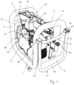
- the compressor 22, the pressure reducer 27, the manometer 28 and the pressure switch 29 are arranged on one side of the partition wall 11 ( 1 ).
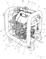
- On the opposite side of the partition wall 11 are the pressure regulators 32, 34, 49 and the directional control valves 35, 40.
- the pressure regulator and directional control valve are arranged one above the other to save space ( 2 ). In this case, these components are arranged adjacent to the frame part 6 .
- the hydropneumatic pump 42, the filter 31, the pressure sensor 48 and the control panel 58 are also located on this side of the partition wall 11.
- the weight is evenly distributed, so that the device can be driven comfortably by the user.
- Corresponding wheels or rollers 60 are mounted on the base frame 1 in the area of the frame parts 4, 6 so that they can rotate freely.
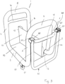
- the frame parts 2, 3 In the area of the opposite frame parts 5, 7, the frame parts 2, 3 have feet 61 on the underside, which give the device a secure footing while working. So that the device can be moved comfortably, it is provided with a swivel bracket 62 ( 1 and 3 ), whose mutually parallel legs 63, 64 are mounted at the free end so as to be freely pivotable about horizontal axes 67.
- the legs 63, 64 are directed downwards from the pivot axes 65, so that they take up little space.
- the bracket 62 is grasped at the web 66, which connects the two legs 63, 64 to one another. It is advantageously formed in one piece with the legs 63, 64.
- the bracket 62 is pivoted up about the horizontal pivot axes 65 on the web 66 .
- the pivot axes 65 are mounted in a U-shaped bearing piece 67 which is attached to the outside of the frame parts 5, 7 is.
- the bearing pieces 67 are provided in such a way that the legs 63, 64 strike the webs 68 of the bearing pieces 67 when the bracket 62 is pivoted up. As a result, the pivoting path of the bracket 62 is limited in a simple manner.
- the bearing pieces 67 are located approximately at the level of the connection areas of the cross strut 15 to the two frame parts 5, 7.
- the two cross struts 14, 15 are on the frame parts 4, 6; 5, 7 attached so that they protrude slightly beyond this to the outside. They therefore offer impact protection if the device should hit a wall, a table and the like while driving, for example.
- the cross braces 14, 15 thereby protect the base frame 1 and/or the components of the device.
- the base frame 1 is designed in such a way that it can accommodate the quantities of compressed air required for testing purposes.
- the capacity of the base frame 1 is chosen so that it can hold 5 liters of compressed air.
- the base frame 1 can also be designed for a larger or smaller amount of compressed air. Since no separate compressed air tank is required for the compressed air tank, the described design of the base frame 1 as a compressed air tank contributes particularly to the compact design of the device, which has a low center of gravity due to the described design.
Landscapes
- Engineering & Computer Science (AREA)
- Mechanical Engineering (AREA)
- General Engineering & Computer Science (AREA)
- Examining Or Testing Airtightness (AREA)
- Cleaning In General (AREA)
- Investigating Strength Of Materials By Application Of Mechanical Stress (AREA)
- Filling Or Discharging Of Gas Storage Vessels (AREA)
Description
- Die Erfindung betrifft ein Gerät zum Spülen und zur Druck- und Dichtheitsprüfung von Leitungen von Trinkwasser- und/oder Heizungssystemen.
- Es sind analoge und digitale Druckprüfgeräte bekannt, mit denen Leitungen auf Druck- und Dichtheit geprüft werden können. Hierzu sind die Geräte mit Handpumpen versehen, mit denen ein gewisser Druck aufgebracht werden kann. Die Vorschriften schreiben immer höhere Drücke für die Druck- und Dichtheitsprüfung vor. Solche Drücke können mit den Handpumpen jedoch nicht mehr erzeugt werden. Aus diesem Grunde ist es erforderlich, zusätzlich zu den Geräten noch elektrische Pumpen zu verwenden, die nicht nur ein zusätzliches, teures Gerät erfordern, sondern die darüber hinaus auch den Prüfvorgang aufgrund der umständlichen Handhabung erschweren.
- Auch wenn die Druck- und Dichtheitsprüfung mit Wasser durchgeführt wird, sind Zusatzgeräte erforderlich, um den geforderten hohen Prüfdruck zu erreichen.
- Insbesondere bei Trinkwasserleitungen ist vorgeschrieben, dass diese gespült und gegebenenfalls auch desinfiziert werden müssen. Hierfür sind weitere Geräte erforderlich.
- Die Druckschrift
CA-A1-2 639 600 offenbart ein Gerät zur Überprüfung von Ventilen, wobei das Gerät eine Leitung mit einem Wasseranschluss, einem Luftanschluss und einem Ausgang zum Anschluss an die zu überprüfenden Ventile aufweist. In dem Wasseranschluss und dem Luftanschluss ist jeweils ein Ventil vorhanden. - Der Erfindung liegt die Aufgabe zugrunde, dass gattungsgemäße Gerät so auszubilden, dass mit ihm kostengünstig und einfach die erforderlichen Spülungen und/oder Prüfungen der Leitungssysteme ausgeführt werden können.
- Diese Aufgabe wird beim gattungsgemäßen Gerät erfindungsgemäß mit den Merkmalen des Anspruches 1 gelöst.
- Das Gerät hat vorzugsweise wenigstens einen Druckerzeuger hat, der auf dem Grundgestell angeordnet ist und den zur Prüfung nach EN 806-4 erforderlichen hohen Druck aufbringen kann. Dafür ist das Gerät mit einem Kompressor und/oder einer Pumpe versehen. Mit diesen Druckerzeugern kann der erforderliche Prüfdruck erzeugt werden. Darum sind zusätzlich zum erfindungsgemäßen Gerät keine Zusatzgeräte erforderlich. Der Handwerker kann darum problemlos die erforderlichen Prüfungen der Leitungssysteme durchführen. Der Druckerzeuger kann für die Druckprüfung mit Luft oder für die Druckprüfung mit Wasser eingesetzt werden.
- Bei der erfindungsgemäßen Ausgestaltung hat das Gerät wenigstens eine Wasserleitung, die mit einem Anschluss für das Wassernetz und mit einem Ausgang versehen ist, an den beispielsweise ein Schlauch angeschlossen werden kann, der das Gerät mit dem zu prüfenden Leitungssystem verbindet. In die Wasserleitung mündet mindestens eine Druckluftleitung, über die Druckluft zugeführt werden kann. Dadurch besteht die Möglichkeit, in das Leitungssystem ein Wasser-Druckluft-Gemisch einzubringen. Diese Vorgehensweise wird beim Spülen der Leitungssysteme eingesetzt. Da in der Druckluftleitung das Schaltventil sitzt, kann der Zutritt der Druckluft zur Wasserleitung je nach Bedarf freigegeben oder gesperrt werden. Es ist daher mit dem Gerät möglich, entweder nur mit Wasser oder mit einem Wasser-Druckluft-Gemisch die Leitungen zu spülen. Das Schaltventil ist vorteilhaft ein 3/2-Wegeventil.
- Die Druckluft kann, wenn das Schaltventil geöffnet ist, kontinuierlich oder auch impulsartig zugeführt werden. Der Anwender des erfindungsgemäßen Gerätes hat dadurch die Möglichkeit, je nach den vorhandenen Verhältnissen das günstigste Spülverfahren mit und ohne Druckluft auszuwählen, wobei die Druckluft darüber hinaus auch noch ständig oder impulsartig zugeführt werden kann.
- In der Druckluftleitung sitzt wenigstens ein Kompressor, mit dem der für den jeweiligen Einsatzfall erforderliche Druck der Druckluft einfach erzeugt werden kann.
- Dem Kompressor ist vorteilhaft mindestens ein Druckluftbehälter nachgeschaltet. Dadurch ist sichergestellt, dass bereits mit Einschalten des Gerätes eine ausreichende Druckluftmenge zur Verfügung steht. Mit dem Kompressor kann der Druckluftbehälter in einfacher Weise mit Druckluft nachgefüllt werden.
- An das Schaltventil ist eine weitere Druckluftleitung angeschlossen. Sie ist mit einem Anschluss versehen, an den mit einem Schlauch oder dergleichen das zu prüfende Leitungssystem angeschlossen werden kann. Über diesen Anschluss ist somit eine Druckprüfung mit Druckluft möglich. In der weiteren Druckluftleitung sitzt ein weiteres Schaltventil, mit dem die weitere Druckluftleitung geöffnet oder gesperrt werden kann, je nach der vom Benutzer des Gerätes durchzuführenden Prüfung.
- Das weitere Schaltventil bildet in vorteilhafter Weise einen Umschalter für eine Druckprüfung mit Luft oder mit Flüssigkeit, vorzugsweise mit Wasser. Je nach Schaltstellung dieses weiteren Schaltventiles kann der Anwender des Gerätes das für die Prüfung erforderliche Medium auswählen.
- Bevorzugt ist das weitere Schaltventil ein 3/2-Wegeventil.
- An das weitere Schaltventil ist bei einer vorteilhaften Ausbildung des Gerätes eine Luftzuführleitung angeschlossen, die ihrerseits dieses weitere Schaltventil mit einem Druckerzeuger für das flüssige Medium verbindet. Je nach Schaltstellung des weiteren Schaltventiles lässt sich somit das Gerät von einer Druckprüfung mit Luft auf eine Druckprüfung mit Flüssigkeit, insbesondere Wasser, umstellen.
- Bei einer weiteren Ausbildung wird der Druckluftbehälter durch einen Grundrahmen des Grundgestelles des erfindungsgemäßen Gerätes gebildet. Der Grundrahmen ist entsprechend hohl und druckdicht ausgebildet. Als Druckluftbehälter ist somit kein gesonderter, auf dem Grundgestell zu befestigender Behälter erforderlich, der zusätzlichen Bauraum benötigen würde. Der Grundrahmen ist ohnehin am Gerät vorgesehen, so dass kein zusätzlicher Bauraum benötigt wird. Das erfindungsgemäße Gerät kann dadurch sehr kompakt ausgebildet sein.
- Der Grundrahmen ist vorteilhaft spiegelsymetrisch zur Längsmittelebene des Grundgestells ausgebildet. Diese Gestaltung des Grundrahmens ermöglicht einen platzsparenden Anbau der verschiedenen Bauteile des Gerätes und trägt zu einer kompakten Bauweise bei. Zudem kann durch diese Gestaltung der Schwerpunkt des Gerätes günstig gelegt werden.
- Bei einer bevorzugten Ausführungsform weist der Grundrahmen zwei u-förmige Rahmenteile auf, die stehend angeordnet sind und durch zwei horizontale Rahmenteile ineinander übergehen. Die u-förmigen Rahmenteile sind vorteilhaft einander gegenüberliegend am Gerät vorgesehen. Die Schenkel dieser Rahmenteile erstrecken sich vorteilhaft nach unten, so dass die horizontalen Rahmenteile im unteren Bereich des Gerätes angeordnet sind. Diese Ausbildung trägt zu einem günstigen tief liegenden Schwerpunkt des Gerätes bei, wodurch die Handhabung des Gerätes wesentlich vereinfacht wird. Der Grundrahmen mit den Rahmenteilen lässt sich sehr einfach herstellen, weil als Ausgangsmaterial Rohre verwendet werden können, die sich einfach in die gewünschte Form biegen und dann in geeigneter Weise druckdicht miteinander verbinden lassen, beispielsweise durch einen Schweißvorgang. Vorteilhaft werden die u-förmigen Rahmenteile so gebogen, dass sie einen Teil der horizontalen Rahmenteile aufweisen. Die horizontalen Rahmenteile der beiden u-förmigen Rahmenteile werden zusammengeschweißt, wodurch sich der Grundrahmen ergibt.
- An den horizontalen Rahmenteilen des Grundrahmens ist vorteilhaft ein Boden befestigt. Auf ihm lassen sich die verschiedenen Bauteile und Aggregate des Gerätes montieren. Der Grundrahmen hat somit nicht nur die Funktion eines Druckluftbehälters, sondern dient auch als Tragrahmen, mit dem die auf dem Boden und/oder am Grundrahmen montierten Bauteile getragen werden.
- Auf dem Boden ist bei einer vorteilhaften Ausführungsform eine stehende Trennwand angeordnet. Mit ihr ist es möglich, im Gerät zwei nebeneinander liegende Einbauräume zu schaffen, in denen die jeweiligen Bauteile beziehungsweise Aggregate montiert werden können. Die Trennwand kann hierbei so ausgebildet sein, dass sie die Komponenten auf der einen und auf der anderen Seite optimal gegeneinander abschirmt, so dass eine gegenseitige Beeinflussung dieser Komponenten nicht möglich ist. So kann die Trennwand beispielsweise als Wärmeschutzwand ausgebildet sein, die dafür sorgt, dass die im Betrieb des Gerätes gebildete Wärme einzelner Aggregate so abgeleitet wird, dass andere Komponenten durch die Wärme nicht beeinträchtigt sind. So kann das Gerät beispielhaft derart aufgebaut sein, dass sich auf einer Seite der Trennwand die wärmeunempfindlichen Bauteile befinden, während auf der anderen Seite die wärmeerzeugenden Bauteile, wie etwa der Kompressor oder die Pumpe, angeordnet sind. Die Trennwand eignet sich auch als Montagewand, an der sich die Komponenten des Gerätes befestigen lassen.
- Die Schaltventile sind vorteilhaft an eine Steuerung angeschlossen. Mit der Steuerung lassen sich die Schaltventile von der Bedienperson in gewünschtem Maße schalten.
- Damit eine einfache Eingabe möglich ist, ist das Gerät vorteilhaft mit wenigstens einem Steuerpult versehen, das mit Eingabeelementen zur Eingabe von Daten und/oder Befehlen in die Steuerung versehen ist. Der Anwender kann am Steuerpult die für den jeweiligen Einsatzfall notwendigen Eingaben ausführen. So kann er das Gerät beispielsweise für einen Spülvorgang einstellen oder für eine Druck- und Dichtheitsprüfung.
- Das Gerät kann auch einen Anschluss für ein druckluftbetriebenes Werkzeug haben. Dieser Anschluss ist vorteilhaft an den Druckluftbehälter angeschlossen. Dadurch besteht für den Benutzer des Gerätes die Möglichkeit, nicht nur die Leitungssysteme zu spülen beziehungsweise zu prüfen, sondern auch im Zusammenhang mit der Verlegung von Leitungen anfallende Installationsarbeiten mit entsprechenden druckluftbetriebenen Werkzeugen durchzuführen.
- Das erfindungsgemäße Gerät ermöglicht dem Anwender, unterschiedlichste Funktionen durchzuführen, wofür nur das einzige Gerät notwendig ist und Zusatzgeräte nicht benötigt werden.
- Weitere Merkmale der Erfindung ergeben sich aus den weiteren Ansprüchen, der Beschreibung und den Zeichnungen.
- Die Erfindung wird anhand eines in den Zeichnungen dargestellten Ausführungsbeispieles näher erläutert. Es zeigen
- Fig. 1
- in perspektivischer Darstellung ein erfindungsgemäßes Gerät,
- Fig. 2
- das erfindungsgemäße Gerät gemäß
Fig. 1 in einer anderen perspektivischen Darstellung, - Fig. 3
- in perspektivischer Darstellung ein Grundgestell des Gerätes gemäß den
Figuren 1 und2 , - Fig. 4
- einen hydropneumatischen Schaltplan des erfindungsgemäßen Gerätes.
- Das im Folgenden beschriebene Gerät hat eine Maximalausstattung, mit der es möglich ist, folgende Gerätefunktionen auszuführen:
- 1. Spülen von Trinkwasser- und Heizungssystemen mit Wasser.
- 2. Spülen von Trinkwasser- und Heizungssystemen mit Wasser und konstanter Druckluft.
- 3. Spülen von Trinkwasser- und Heizungssystemen mit Wasser und Druckluftimpulsstößen.
- 4. Desinfektion und Konservierung von Trinkwasser- und Heizungssystemen.
- 5. Druck- und Dichtheitsprüfung von Trinkwasser- und Heizungssystemen mit Druckluft.
- 6. Antrieb von Druckluftwerkzeugen.
- 7. Aufpumpen von Behältern aller Art (Luftpumpe).
- 8. Druck- und Dichtheitsprüfung von Trinkwasser- und Heizungssystemen mit Wasser.
- Mit dem Gerät erhält der Anwender die Möglichkeit, die oben angegebenen acht Funktionen auszuführen, ohne dass er weitere Geräte hierzu benötigt. Das Gerät kann aber auch so ausgestattet sein, dass mit ihm nur die Funktion 5 oder die Funktion 8 oder auch beide Funktionen 5 und 8 ausgeführt werden können. Weiter ist es möglich, das Gerät so auszustatten, dass es die Funktionen 1 bis 7 ausführen kann. In der Maximalausstattung kann das Gerät alle Funktionen 1 bis 8 ausführen.
- Das Gerät hat einen Grundrahmen 1 (
Fig. 3 ), der zwei parallel zueinander liegende Rahmenteile 2, 3 aufweist. Die beiden Rahmenteile 2, 3 gehen an beiden Enden jeweils bogenförmig gekrümmt in aufwärts gerichtete Rahmenteile 4, 5; 6, 7 über. Die Rahmenteile 4 bis 7 verlaufen parallel zueinander sowie senkrecht zu den beiden unteren Rahmenteilen 2, 3. Am oberen Ende gehen die Rahmenteile 4, 6 bogenförmig gekrümmt in einen Rahmenteil 8 und die Rahmenteile 5, 7 bogenförmig gekrümmt in einen Rahmenteil 9 über. Die beiden Rahmenteile 8, 9 liegen parallel zueinander und vorteilhaft auf gleicher Höhe. Aufgrund der beschriebenen Ausbildung wird der Grundrahmen 1 an den beiden Längsseiten des Gerätes durch die u-förmig zueinander liegenden Rahmenteile 2, 4, 5 bzw. 3, 6, 7 gebildet, die durch den oberen Rahmenteil 9, 8 miteinander verbunden sind. Diese u-förmigen Rahmenbereiche zeichnen sich dadurch aus, dass die Rahmenteile 4, 5 und 6, 7 vom unteren Rahmenteil 2, 3 aufwärts verlaufen. - An den beiden Schmalseiten des Gerätes wird der Grundrahmen 1 durch die u-förmig angeordneten Rahmenteile 4, 6, 8 und 5, 7, 9 gebildet, wobei die Rahmenteile 4, 6 und 5, 7 vom oberen Rahmenteil 8, 9 aus sich nach unten erstrecken. Die u-förmigen Rahmenteile werden aus zwei Rohren hergestellt. Sie werden so gebogen, dass die u-förmigen Rahmenteile 4, 6, 8 und 5, 7, 9 noch einen Teil der horizontalen Rahmenteile 2, 3 aufweisen. Die so gebogenen Rahmenteile werden mit den horizontalen Abschnitten aneinandergesetzt und miteinander druckdicht verschweißt. Die horizontalen Abschnitte bilden die Rahmenteile 2, 3 des Grundrahmens 1. Die Schweißstelle, die sich vorteilhaft in halber Länge der Rahmenteile 2, 3 befindet, ist in
Fig. 3 durch eine gestrichelte Linie angegeben. - Aufgrund der beschriebenen Gestaltung des Grundrahmens 1 hat das Gerät eine hohe Steifigkeit.
- Zwischen den beiden unteren Rahmenteilen 2, 3 ist ein Boden 10 befestigt, der vorzugsweise durch eine Platte gebildet wird. Im Bereich zwischen den beiden Rahmenteilen 2, 3 befindet sich eine Trennwand 11, die sich senkrecht zum Boden 10 erstreckt und auf ihm befestigt ist. Die Trennwand 11 wird ebenfalls vorteilhaft durch eine Platte gebildet, die im Ausführungsbeispiel rechteckigen Umriss hat und sich über die gesamte Länge des Bodens 10 erstreckt. Die aufwärts verlaufenden Schmalseiten 12, 13 der Trennwand 11 sind jeweils abgewinkelt. Die Schmalseite 12 ist u-förmig abgewinkelt. Die gegenüber liegende Schmalseite 13 ist lediglich rechtwinklig abgebogen. Die Form dieser Schmalseiten 12, 13 richtet sich nach denjenigen Aggregaten, die am Boden 10 und/oder an der Trennwand 11 montiert werden sollen.
- Zur Versteifung des Grundrahmens 1 sind die beiden Rahmenteile 4, 6 durch eine Querstrebe 14 miteinander verbunden, die sich mit geringem Abstand unterhalb des Rahmenteiles 8 befindet. Auch die gegenüber liegenden vertikalen Rahmenteile 5, 7 sind mit geringem Abstand unterhalb des Rahmenteiles 9 durch eine Querstrebe 15 miteinander verbunden. Im dargestellten Ausführungsbeispiel befinden sich die beiden Querstreben 14, 15 auf gleicher Höhe, können aber, je nach Gestaltung des Gerätes, auch in unterschiedlicher Höhe vorgesehen sein. Die Trennwand 11 kann je nach Aufbau des Gerätes unterschiedlich hoch sein. Im dargestellten Ausführungsbeispiel liegt der obere Rand der Trennwand 11 mit Abstand im Bereich unterhalb der Querstreben 14, 15, in Längsrichtung der Rahmenteile 2, 3 gesehen.
- Der Grundrahmen 1 hat nicht nur eine Stütz- und Tragfunktion für das Gerät und die Aggregate, sondern dient auch als Druckluftbehälter. Dementsprechend sind die Rahmenteile 2 bis 9 durch Rohre gebildet, die druckdicht miteinander verbunden sind. Darum wird kein gesonderter Behälter für die Druckluft benötigt, so dass das Gerät insgesamt kompakt ausgebildet sein kann.
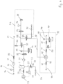
- Anhand des Hydropneumatik-Schaltplanes gemäß
Fig. 4 wird zunächst der Aufbau des Gerätes erläutert. Es hat einen Wasseranschluss 16, über den das Gerät an das Wassernetz angeschlossen werden kann. In der an den Wasseranschluss 16 anschließenden Wasserleitung 17 befindet sich ein Druckaufnehmer 18, dem ein Wasserzähler 19 und ein Rückschlagventil 20 in der Wasserleitung 17 nachgeschaltet sind. Das Rückschlagventil 20 verhindert, dass das Wasser zurück in Richtung auf den Wasseranschluss 16 gelangt. Die Wasserleitung 17 hat einen Auslass 21, über den das Wasser in die zu spülenden und/oder zu prüfenden Wasserleitungen der jeweiligen Installation gelangt. Der Auslass 21 ist ebenso wie der Wasseranschluss 16 als Kupplung ausgebildet, so dass ein einfacher Anschluss an das Wassernetz bzw. an die Installations-Wasserleitungen, ggf. über Schlauchstücke, möglich ist. Die Wasserleitung 17 verläuft, wie sich aus denFig. 1 und2 ergibt, im Wesentlichen horizontal durch das Gerät. Der Wasseranschluss 16 befindet sich im Bereich zwischen dem oberen Rahmenteil 8 und der Querstrebe 14. Der Auslass 21 an der gegenüber liegenden Seite des Gerätes befindet sich zwischen dem oberen Rahmenteil 9 und der Querstrebe 15. Damit ein einfacher Anschluss möglich ist, ragen der Wasseranschluss 16 und/oder der Auslass 21 geringfügig nach außen vor. Da sich der Wasseranschluss 16 und der Auslass 21 nahe den oberen Rahmenteilen 8, 9 befinden, kann der Benutzer des Gerätes diese Anschlüsse bequem erreichen. - Soll das Leitungssystem der jeweiligen Installation mit Wasser gespült werden, wird das Gerät über den Wasseranschluss 16 an das Wassernetz angeschlossen. Über den Auslass 21 wird die Verbindung zu den Leitungen der Installation hergestellt. Es können dann die Leitungsrohre der Installation mit Wasser gespült werden. Über den Druckaufnehmer 18 lässt sich der zum Durchspülen der Rohre erforderliche Wasserdruck zuverlässig ermitteln. Mit Hilfe des Wasserzählers 19 lässt sich die durchfließende Wassermenge zuverlässig bestimmen.
- Bei den Leitungen kann es sich um Trinkwasser- und/oder um Heizungsleitungen handeln, die mit Wasser gespült werden. Mit dem Gerät lassen sich generell alle Leitungen mit gasförmigen oder flüssigen Medien spülen bzw. prüfen, z.B. Gasleitungen, Förderleitungen und dgl.
- Hinsichtlich der Spülung, der Druckprüfung und Dichtheitsprüfung sind Vorschriften zu beachten, insbesondere EN 806-4.
- Mit dem Gerät ist auch eine Spülung mit Wasser und konstant zugeführter Druckluft möglich. Hierfür ist das Gerät mit einem Kompressor 22 versehen, der auf dem Boden 10 aufstehend befestigt ist. An den Kompressor 22 ist eine Druckluftleitung 23 angeschlossen, die den Kompressor 22 mit dem Druckluftbehälter 1 verbindet, der durch den Grundrahmen des Gerätes gebildet ist. Zwischen dem Kompressor 22 und dem Druckluftbehälter 1 sitzt in der Druckluftleitung 23 ein gegen den Kompressor 22 schließendes Rückschlagventil 24. An den Druckluftbehälter 1 ist eine Zuführleitung 25 angeschlossen, die den Druckluftbehälter 1 mit einem Anschluss 26 für ein Druckluftwerkzeug verbindet. Der Installateur kann somit wahlweise an den Anschluss 26 Druckluftwerkzeuge anschließen, wie sie häufig bei Sanitärinstallationen eingesetzt werden. In der Zuführleitung 25 sitzt ein Druckminderer 27, mit dem der Druck auf den für das an den Anschluss 26 angeschlossene Druckluftwerkzeug angepasst werden kann. Zur Überwachung des geminderten Druckes setzt in der Zuführleitung 25 zwischen dem Anschluss 26 und dem Druckminderer 27 vorteilhaft ein Manometer 28. Wie aus
Fig. 1 hervorgeht, befindet sich das Manometer 28 gut ablesbar im Bereich zwischen den beiden Rahmenteilen 4 und 5 des Grundrahmens 1. Der Druckminderer 27 ist ebenfalls in diesem Bereich neben dem Manometer 28 vorgesehen (Fig. 1 ). - Im Bereich zwischen dem Druckluftbehälter 1 und dem Druckminderer 27 sitzt in der Zuführleitung 25 ein Druckschalter 29, der als Notaus im Gefahrenfalle dient, mit dem der Kompressor 22 abgeschaltet werden kann. Wie
Fig. 1 zeigt, befindet sich der Druckschalter 29 an einer gut zugänglichen Stelle des Gerätes im Bereich zwischen den beiden oberen Rahmenteilen 8 und 9. - Die Druckluftleitung 23 mündet in die Wasserleitung 17 und ist gegenüber dieser durch ein Rückschlagventil 30 abgesichert. Es verhindert, dass Wasser aus der Wasserleitung 17 in die Druckluftleitung 23 gelangt. Dem Druckluftbehälter 1 nachgeschaltet ist ein Filter 31, der aus der durch die Druckluftleitung 23 strömenden Druckluft Verunreinigungen ausfiltert. In der Druckluftleitung 23 sitzt hinter dem Filter 31 ein Druckregler 32, mit dem der Durchgang der Druckluft zur Wasserleitung 17 gesteuert werden kann. In
Fig. 4 befindet sich der Druckregler 32 in seiner Sperrstellung, so dass keine Druckluft in die Wasserleitung 17 gelangt. - Dem Druckregler 32 nachgeschaltet ist ein Druckaufnehmer 33, der den Druckregler 34 schaltet. Der Druckaufnehmer 33 ist im Ausführungsbeispiel für einen Druckbereich bis etwa 10 bar ausgelegt. Mit dem Druckregler 34 kann ein zu hoher Druck in der Druckluftleitung abgebaut werden. In
Fig. 4 befindet sich der Druckregler 34 in seiner Sperrstellung, so dass bei durch den Druckregler 32 freigegebener Druckluftleitung 23 der Druck nicht abgebaut wird. Sollte der Druck der Druckluft über einen vorgegebenen Wert ansteigen, wird der Druckregler 34 in seine Durchlassstellung verstellt, so dass ein zu hoher Druck in der Druckluftleitung 23 entsprechend abgebaut werden kann. Der Druckregler 34 wird über eine entsprechende Steuerung automatisch geschaltet, so dass gewährleistet ist, dass bei geöffnetem Druckregler 32 die Druckluft mit dem vorgeschriebenen Druck in die Wasserleitung 17 eingebracht wird. - Zwischen dem Druckregler 34 und dem Rückschlagventil 30 sitzt in der Druckluftleitung 23 ein Schaltventil 35, das vorteilhaft ein 3/2-Wegeventil ist. Es befindet sich in der Darstellung gemäß
Fig. 4 in Durchlassstellung. - Soll die an den Auslass 21 des Gerätes angeschlossene Installation durch ein Gemisch von Wasser und Druckluft gespült werden, dann wird der Druckregler 32 in die Durchlassstellung verstellt, so dass die Druckluft über die Leitung 23 in die Wasserleitung 17 gelangt. Der Anschluss der Druckluftleitung 23 an die Wasserleitung 17 befindet sich im Bereich zwischen dem Rückschlagventil 20 und dem Auslass 21. Durch den Druckaufnehmer 33 in Verbindung mit dem Druckregler 34 ist gewährleistet, dass die Druckluft mit dem erforderlichen Druck in die Wasserleitung 17 gelangt. Die Druckluft kann kontinuierlich oder impulsartig in die Wasserleitung 17 eingegeben werden, je nach dem gewünschten Spülverfahren.
- Das Gerät bietet auch die Möglichkeit, die Leitungen der Installation mittels einer Druckprüfung mit Luft zu untersuchen. Hierfür ist das Modul 36 vorgesehen (
Fig. 4 ). Es hat eine Druckluftleitung 39, die mit einem Druckluftanschluss 37 versehen ist. Die Druckluftleitung 39 ist über ein Wegeventil 40 an eine Luftzuführleitung 41 anschließbar. Das Wegeventil 40 ist im Ausführungsbeispiel ein 3/2-Wegeventil. Mit dem Wegeventil 40 kann das Gerät umgeschaltet werden von einer Druckprüfung mit Luft auf eine Druckprüfung mit Wasser. - Die Luftzuführleitung 41 ist an eine Pumpe 42 angeschlossen, die eine hydropneumatische Pumpe ist, mit der Wasser aus einer Wasserleitung 43 gepumpt werden kann. Die Wasserleitung 43 hat einen Anschluss 44, über den das Gerät an das Wassernetz angeschlossen werden kann. Die Wasserleitung 43 ist durch ein Rückschlagventil 45 gegen das Wassernetz gesichert.
- Mit der hydropneumatischen Pumpe 42 wird das Wasser einem Ausgang 46 zugeführt, über den das Gerät mit den zu prüfenden Leitungen der Installation verbunden werden kann, beispielsweise über einen Druckschlauch.
- In der Wasserleitung 43 sitzt der hydropneumatischen Pumpe 42 nachgeschaltet ein Rückschlagventil 47, das gegen die hydropneumatische Pumpe 42 schließt.
- Dem Ausgang 46 vorgeschaltet ist ein Druckaufnehmer 48, der einen Druckregler 49 schaltet. Der Druckaufnehmer 48 ist auf einen Druckbereich beispielsweise bis etwa 40 bar ausgelegt. Mit dem Druckaufnehmer 48 kann der Druck des Wassers in der Wasserleitung 43 auf einem vorgegebenen Wert gehalten werden. Sollte der Wasserdruck zu hoch sein, dann wird der Druckregler 49 umgeschaltet, so dass über den nunmehr offenen Druckregler 49 der Wasserdruck abgebaut werden kann. Sobald der Wasserdruck den erforderlichen, für die Prüfung vorgesehenen Wert erreicht, wird der Druckregler 49 wieder in seine in
Fig. 4 dargestellte Sperrstellung verstellt. - Dem Rückschlagventil 47 nachgeschaltet ist ein Sicherheitsventil 50, das bei Überschreiten eines maximalen Druckes in der Wasserleitung 43 öffnet, so dass der Druck abgebaut werden kann. In
Fig. 4 ist das Sicherheitsventil 50 in der Schließstellung dargestellt. Zwischen dem Sicherheitsventil 50 und dem Druckaufnehmer 48 sowie dem Druckregler 49 liegt ein Rückschlagventil 51, das in Richtung auf das Sicherheitsventil 50 schließt. - Die Wasserleitung 43 mit der hydropneumatischen Pumpe 42, dem Druckaufnehmer 48, dem Druckregler 49 und dem Sicherheitsventil 50 bilden ein Modul 52, mit dem eine Druckprüfung mit Wasser der Leitungen der Installation durchgeführt werden kann.
- An die hydropneumatische Pumpe 42 ist die Luftzuführleitung 41 angeschlossen, die über das Wegeventil 40 an eine Druckluftleitung 53 anschließbar ist. Sie ist an das Wegeventil 35 angeschlossen und weist ein Wegeventil 54 auf, das vorteilhaft ein Magnetventil ist. Die Druckluftleitung 53 ist durch ein Sicherheitsventil 55 abgesichert, das bei Überschreiten eines vorgegebenen Drucks öffnet. Im Ausführungsbeispiel ist das Sicherheitsventil 55 so ausgelegt, dass es bei Überschreiten eines Druckes von 1,8 bar öffnet. Selbstverständlich ist dieser Druckwert nicht als beschränkend anzusehen.
- Zwischen dem Sicherheitsventil 55 und dem Wegeventil 54 sitzt in der Druckluftleitung 53 ein Druckaufnehmer 56, der im Ausführungsbeispiel für einen Druckbereich bis etwa 200 mbar ausgelegt ist.
- Das Wegeventil 54, das Sicherheitsventil 55, der Druckaufnehmer 56 und der Druckluftanschluss 37 sind Bestandteil des Moduls 36, mit dem eine Druckprüfung mit Luft des Leitungssystems der Installation vorgenommen werden kann. Im Ausführungsbeispiel ist das Modul 36 so ausgelegt, dass es für eine Druckprüfung mit Luft von 150 mbar oder mit 3 bar eingesetzt werden kann. Darüber hinaus ist es in vorteilhafter Weise möglich, über den Druckluftanschluss 37 ein Desinfektionsmittel beizumischen. Der Druckluftanschluss 37 kann auch zum Aufpumpen von Behältern aller Art herangezogen werden (Luftpumpe). Der Druck kann über den Druckaufnehmer 33 und den Druckregler 32 eingestellt werden.
- Die Luftzuführleitung 41 ist im Bereich zwischen dem Wegeventil 35 und dem Wegeventil 54 an die Druckluftleitung 53 angeschlossen.
- In der Stellung nach
Fig. 4 ist das Wegeventil 54 in seiner Schließstellung. Das Wegeventil 40 ist so geschaltet, dass die Druckluftleitung 39 mit der Druckluftleitung 53 verbunden ist. Das Wegeventil 35 ist jedoch so geschaltet, dass die Druckluftleitung 53 nicht mit der Druckluftleitung 23 verbunden ist. Die Luftzuführleitung 41 ist durch das Wegeventil 40 gegenüber der Druckluftleitung 53 abgesperrt. Da sich der Druckregler 32 in Sperrstellung befindet, ist die Druckluftleitung 23 gegenüber der Wasserleitung 17 gesperrt.
Das Gerät wird bei diesem Schaltzustand über den Wasseranschluss 16 an das Wassernetz angeschlossen. An den Auslass 21 wird über einen Schlauch das Leitungssystem der zu spülenden Installation angeschlossen. Durch Öffnen eines (nicht dargestellten) Hahns wird die Wasserleitung 17 freigegeben, so dass das Wasser aus dem Wassernetz in das Leitungssystem der Installation gelangt, das dadurch im erforderlichen Maße durchgespült wird. Das Leitungssystem kann insbesondere ein Trinkwasser- oder ein Heizungssystem sein. Der Spülvorgang muss bei einer Trinkwasser-Installation möglichst bald nach der Installation und einer Druckprüfung sowie unmittelbar vor der Inbetriebnahme mit Trinkwasser gespült werden (EN 806-4). Die Prüfvorschriften schreiben vor, dass in regelmäßigen Abständen (bis zu 7 Tagen) gespült werden muss, wenn das Leitungssystem nicht unmittelbar nach der Inbetriebnahme in Betrieb genommen wird. Mit dem Gerät ist es einfach und zuverlässig möglich, diesen erforderlichen Spülvorgang vorzunehmen. - Nach EN 806-4 ist es auch möglich, das Leitungssystem der Installation mit einem Wasser-Luft-Gemisch zu spülen. Um dies zu ermöglichen, wird der Druckregler 32 aus der Sperr- in die Durchlassstellung verstellt. Damit kann die Druckluft aus dem Druckluftbehälter 1 über das Filter 31 und das Wegeventil 35 in die Wasserleitung 17 gelangen. Somit strömt aus dem Auslass 21 ein Wasser-Luft-Gemisch, mit dem das Leitungssystem der Installation gespült wird. Die Druckluft kann hierbei kontinuierlich zugeführt werden. Es ist aber auch möglich, in das Wasser in der Wasserleitung 17 Druckluft impulsartig einzubringen. Die Druckluftimpulsstöße können beispielsweise dadurch erzeugt werden, dass der Druckregler 32 in Zeitabständen immer wieder geöffnet und geschlossen wird.
- Mit dem Gerät ist es auch möglich, eine Desinfektion des Leitungssystems durchzuführen. Das Desinfektionsmittel befindet sich in einem Behältnis, das an den Auslass 37 angeschlossen wird. Hierfür kann an den Auslass 37 ein T-Kupplungsstück angeschlossen werden. Der Anschluss für die Druckluftleitung 39 befindet sich im T-Fuß des T-Stückes. An den T-Fuß wird das Desinfektionsbehältnis angeschlossen. Der T-Steg ist an einem Ende mit dem Auslass 37 und mit dem anderen Ende an das Leitungssystem der Installation angeschlossen. Das Wegeventil 35 ist aus der in
Fig. 4 dargestellten Stellung umgeschaltet, so dass die vom Druckluftbehälter 1 kommende Druckluft über die Druckluftleitung 23, das umgeschaltete Wegeventil 35, die Druckluftleitung 53, das Wegeventil 40 und die Druckluftleitung 39 zum Anschluss 37 gelangt. - Mit dem Gerät kann außerdem eine Druck- und Dichtheitsprüfung des Trinkwasser- und des Heizungssystems der Installation mit Druckluft durchgeführt werden. Eine solche Prüfung ist im ZVSHK-Merkblatt T 82-2011 "Dichtheitsprüfungen von Trinkwasser-Installationen mit Druckluft, Inertgas oder Wasser" festgelegt. Hierbei wird vorgeschrieben, zunächst eine Vorprüfung mit 150 mbar durchzuführen. Für diese Vorprüfung sind bestimmte Prüfzeiten vorgeschrieben. Im Anschluss daran ist eine Belastungsprüfung (Hauptprüfung) durchzuführen, bei der der Druck auf z.B. 3 bar erhöht wird. Auch dieses Prüfverfahren kann mit dem Gerät in einfacher Weise durchgeführt werden. Für die Druckprüfung mit Luft wird an den Druckluftanschluss 37 ein Druckluftschlauch angeschlossen, der seinerseits an das Leitungssystem der Installation angeschlossen wird. Das Wegeventil 35 wird aus der Stellung gemäß
Fig. 4 umgeschaltet, so dass die Druckluft vom Kompressor 22 bzw. vom Druckluftbehälter 1 über die Leitung 23 und das umgeschaltete Wegeventil 35 sowie über das Wegeventil 40, das die Stellung gemäßFig. 4 einnimmt, in die Druckluftleitung 39 gelangt. Für die Vorprüfung mit dem geringen Druck (150 mbar) wird das Wegeventil 54 aus der Stellung gemäßFig. 4 umgeschaltet. Mit dem Druckaufnehmer 56 wird der erforderliche geringe Druck erfasst und der Druckregler 34 entsprechend geregelt. Der Druckregler 34 stellt sicher, dass bei Überschreiten dieses Vorprüfungsdruckes der Druck entsprechend abgebaut wird. Das nachgeschaltete Sicherheitsventil 55 schützt den Druckaufnehmer 56. - Nach Durchführung der Vorprüfung innerhalb der vorgeschriebenen Prüfzeit wird das Wegeventil 54 in die in
Fig. 4 dargestellte Stellung zurückgeschaltet. Dies hat zur Folge, dass nunmehr am Druckluftauslass 37 der notwendige höhere Prüfdruck (bis z.B. 3 bar) bereitgestellt werden kann. Der Druckaufnehmer 33 ist für diesen Druckbereich ausgelegt, so dass gewährleistet ist, dass die Druckluft im erforderlichen Prüfdruck über den Druckluftauslass 37 in das Leitungssystem gelangt. Sollte der Prüfdruck überschritten werden, wird über den Druckregler 34 der Druck entsprechend abgebaut. - Schließlich ist es mit dem Gerät auch möglich, eine Druck- und Dichtheitsprüfung von Trinkwasser durchzuführen. Die entsprechenden Vorschriften hierfür finden sich in EN 806-4:2010 und ZVSHK-Merkblatt T 82-2011. Je nach Art des Leitungssystems (Metallrohre, Kunststoffrohre, Mehrschichtverbundrohre und dgl.) sind unterschiedliche Prüfbedingungen vorgesehen.
- Die Druckprüfung mit Wasser erfolgt mit Hilfe des Moduls 52. Über den Anschluss 44 erfolgt die Verbindung zum Wassernetz. Die hydropneumatische Pumpe 42 fördert das Wasser über die Wasserleitung 43 zum Ausgang 46, über den das Gerät mit dem Leitungssystem der Installation verbunden wird. Die Wegeventile 35 und 40 werden aus der Stellung gemäß
Fig. 4 umgeschaltet, so dass die Druckluft vom Kompressor 22 bzw. vom Druckluftbehälter 1 über die Druckluftleitungen 23, 53 in die Luftzuführleitung 41 gelangt. Die hydropneumatische Pumpe 42 wird zur Erzeugung des notwendigen Wasserdrucks dementsprechend mit der notwendigen Druckluft versorgt. - Am Ausgang 46 steht somit der für die Druckprüfung mit Wasser erforderliche Prüfdruck zur Verfügung. Der Druckaufnehmer 48 in Verbindung mit dem Druckregler 49 stellen sicher, dass bei Überschreiten des Prüfdruckes durch Öffnen des Druckreglers 49 der Druck entsprechend abgebaut wird.
- Mit dem beschriebenen Gerät in der Maximalausstattung können sämtliche Spül-, Desinfektions- und Druck-/Dichtheitsprüfungen von Leitungssystemen durchgeführt werden. Für die einzelnen Funktionen sind somit keine eigenen Geräte erforderlich. Für den Anwender ist dies eine große Erleichterung, da er mit ein und demselben Gerät die unterschiedlichsten Funktionen wahlweise durchführen kann. Der Anwender hat an der Baustelle mit dem Gerät alle Möglichkeiten, je nach Bedarf die unterschiedlichen Vorgänge durchzuführen. Die Umsteuerung der verschiedenen Ventile erfolgt mittels einer Software, die über ein Bedienfeld 57 eines Steuerpults 58 vom Benutzer betätigt werden kann. Er wird menügesteuert durch das Programm geführt, wobei die einzelnen Einstellungen auf einem Display 59 gut sichtbar angezeigt werden. Das Bedienfeld 57 hat Eingabeelemente, mit denen der Anwender die erforderlichen Einstellungen zuverlässig vornehmen kann. Das Steuerpult 58 befindet sich im oberen Bereich des Gerätes (
Fig. 2 ) und ist geneigt angeordnet, so dass der Bediener das Bedienfeld 57 einfach betätigen und das Display 59 gut beobachten kann. - Die einzelnen Komponenten des Gerätes sind beiderseits der Trennwand 11 angeordnet, so dass sich eine sehr kompakte und niedrige Bauweise des Gerätes ergibt. So sind der Kompressor 22, der Druckminderer 27, das Manometer 28 und der Druckschalter 29 auf der einen Seite der Trennwand 11 angeordnet (
Fig. 1 ). Auf der gegenüber liegenden Seite der Trennwand 11 befinden sich die Druckregler 32, 34, 49 und die Wegeventile 35, 40. Die Druckregler und Wegeventil sind platzsparend übereinander angeordnet (Fig. 2 ). Dabei sind diese Bauteile benachbart zum Rahmenteil 6 angeordnet. Auf dieser Seite der Trennwand 11 befinden sich auch die hydropneumatische Pumpe 42, das Filter 31, der Druckaufnehmer 48 und das Steuerpult 58. - Aufgrund der Verteilung der verschiedenen Komponenten beiderseits der Trennwand 11 ergibt sich eine gleichmäßige Gewichtsverteilung, so dass das Gerät bequem vom Benutzer gefahren werden kann. Am Grundrahmen 1 sind entsprechende Räder bzw. Rollen 60 im Bereich der Rahmenteile 4, 6 frei drehbar gelagert. Im Bereich der gegenüber liegenden Rahmenteile 5, 7 sind an der Unterseite der Rahmenteile 2, 3 Füße 61 vorgesehen, die dem Gerät während des Arbeitens einen sicheren Stand verleihen.
Damit das Gerät bequem gefahren werden kann, ist es mit einem schwenkbaren Bügel 62 versehen (Fig. 1 und3 ), dessen parallel zueinander liegende Schenkel 63, 64 am freien Ende um horizontale Achsen 67 frei schwenkbar gelagert sind. In der in denFig.1 und3 dargestellten Ruhelage sind die Schenkel 63, 64 von den Schwenkachsen 65 aus nach unten gerichtet, so dass sie nur wenig Raum beanspruchen. Zum Verfahren des Gerätes wird der Bügel 62 am Steg 66 erfasst, der die beiden Schenkel 63, 64 miteinander verbindet. Er ist vorteilhaft einstückig mit den Schenkeln 63, 64 ausgebildet. Am Steg 66 wird der Bügel 62 um die horizontalen Schwenkachsen 65 hochgeschwenkt. Die Schwenkachsen 65 sind in einem u-förmigen Lagerstück 67 gelagert, das an der Außenseite der Rahmenteile 5, 7 befestigt ist. Die Lagerstücke 67 sind so vorgesehen, dass die Schenkel 63, 64 beim Hochschwenken des Bügels 62 an den Stegen 68 der Lagerstücke 67 anschlagen. Dadurch wird der Schwenkweg des Bügels 62 in einfacher Weise begrenzt. - Die Lagerstücke 67 befinden sich etwa in Höhe der Anschlussbereiche der Querstrebe 15 an die beiden Rahmenteile 5, 7. Die beiden Querstreben 14, 15 sind so an den Rahmenteilen 4, 6; 5, 7 befestigt, dass sie geringfügig über diese nach außen vorstehen. Sie bieten daher einen Aufprallschutz, wenn das Gerät beim Fahren beispielsweise gegen eine Wand, einen Tisch und dgl. stoßen sollte. Die Querstreben 14, 15 schützen dadurch den Grundrahmen 1 und/oder die Komponenten des Gerätes.
- Der Grundrahmen 1 ist so gestaltet, dass er die für Prüfzwecke erforderlichen Mengen an Druckluft aufnehmen kann. Beispielhaft ist das Fassungsvermögen des Grundrahmens 1 so gewählt, dass er 5 Liter Druckluft aufnehmen kann. Je nach Anwendungsfall kann der Grundrahmen 1 aber auch für eine größere oder kleinere Druckluftmenge ausgelegt sein. Da für den Druckluftbehälter kein eigenes Druckluftbehältnis erforderlich ist, trägt die beschriebene Gestaltung des Grundrahmens 1 als Druckluftbehälter in besonderem Maße zur kompakten Bauweise des Gerätes bei, das infolge der beschriebenen Bauweise einen günstig tief liegenden Schwerpunkt hat.
Claims (12)
- Gerät zum Spülen und zur Druck- und Dichtheitsprüfung von Leitungen von Trinkwasser- und/oder Heizungssystemen, mit einem Grundgestell (1), wobei das Gerät wenigstens eine Wasserleitung (17, 43) mit einem Wassernetzanschluss (16, 44) und wenigstens einen Ausgang (21, 46) zum Anschluss an die Leitungen des Trinkwasser- und/oder Heizungssystems aufweist, wobei in die Wasserleitung (17) wenigstens eine Druckluftleitung (23) mündet, die gegen die Wasserleitung (17) durch ein Rückschlagventil (30) gesichert ist und in der ein Schaltventil (35), vorzugsweise ein 3/2-Wegeventil, mit dem der Zutritt der Druckluft zur Wasserleitung (17) wahlweise sperrbar und freigebbar ist, und ein Kompressor (22) sitzen, hinter dem ein Druckregler (32) sitzt, mit dem der Durchgang der Druckluft zur Wasserleitung (17) steuerbar und dem ein Druckaufnehmer (33) nachgeschaltet ist, der einen Druckregler (34) schaltet, der über eine Steuerung automatisch geschaltet wird, wobei in der Wasserleitung (17, 43) ein Rückschlagventil (20, 45) sitzt, das die Wasserleitung (17, 43) gegen den Wassernetzanschluss (16, 44) sichert, wobei an das Schaltventil (35) eine weitere Druckluftleitung (53) angeschlossen ist, die durch ein Sicherheitsventil (55) abgesichert und mit einem Anschluss (37) für die Leitungen zur Druckprüfung mit Luft versehen ist und in der ein weiteres Schaltventil (40) sitzt, das vorteilhaft ein Umschalter für die Druckprüfung mit Luft oder mit Flüssigkeit ist, wobei zwischen dem Sicherheitsventil (55) und einem Wegeventil (54) ein weiterer Druckaufnehmer (56) in der weiteren Druckluftleitung (53) sitzt.
- Gerät nach Anspruch 1,
dadurch gekennzeichnet, dass dem Kompressor (22) wenigstens ein Druckluftbehälter (1) nachgeschaltet ist. - Gerät nach Anspruch 1 oder 2,
dadurch gekennzeichnet, dass das weitere Schaltventil (40) ein 3/2-Wegenventil ist. - Gerät nach einem der Ansprüche 1 bis 3,
dadurch gekennzeichnet, dass an das weitere Schaltventil (40) über eine Luftzuführleitung (41) der Druckerzeuger (42) für das flüssige Medium angeschlossen ist. - Gerät nach einem der Ansprüche 1 bis 4,
dadurch gekennzeichnet, dass der Druckluftbehälter (1) ein Grundrahmen des Grundgestelles ist. - Gerät nach Anspruch 5,
dadurch gekennzeichnet, dass der Grundrahmen (1) spiegelsymmetrisch zur Längsmittelebene des Grundgestells ausgebildet ist. - Gerät nach Anspruch 5 oder 6,
dadurch gekennzeichnet, dass der Grundrahmen (1) zwei u-förmige Rahmenteile (4, 6, 8; 5, 7, 9) aufweist, die stehend angeordnet sind und durch zwei horizontale Rahmenteile (2, 3) ineinander übergehen. - Gerät nach Anspruch 7,
dadurch gekennzeichnet, dass an den horizontalen Rahmenteilen (2, 3) ein Boden (10) befestigt ist. - Gerät nach Anspruch 8,
dadurch gekennzeichnet, dass auf dem Boden (10) eine stehende Trennwand (11) angeordnet ist. - Gerät nach einem der Ansprüche 1 bis 9,
dadurch gekennzeichnet, dass die Schaltventile (35, 40) an eine Steuerung angeschlossen sind. - Gerät nach Anspruch 10,
dadurch gekennzeichnet, dass das Gerät mit wenigstens einem Steuerpult (58) versehen ist, das mit Eingabeelementen zur Eingabe von Daten und/oder Befehlen in die Steuerung versehen ist. - Gerät nach einem der Ansprüche 1 bis 11,
dadurch gekennzeichnet, dass an den Druckluftbehälter (1) ein Anschluss (26) für ein druckluftbetriebenes Werkzeug angeschlossen ist.
Applications Claiming Priority (1)
| Application Number | Priority Date | Filing Date | Title |
|---|---|---|---|
| DE201310010832 DE102013010832A1 (de) | 2013-06-21 | 2013-06-21 | Gerät zum Spülen und/oder zur Druck - und Dichtheitsprüfung von Leitungen, insbesondere von Trinkwasser- und/oder Heizungssystemen |
Publications (3)
| Publication Number | Publication Date |
|---|---|
| EP2816231A1 EP2816231A1 (de) | 2014-12-24 |
| EP2816231B1 EP2816231B1 (de) | 2020-08-26 |
| EP2816231B2 true EP2816231B2 (de) | 2023-05-10 |
Family
ID=50846747
Family Applications (1)
| Application Number | Title | Priority Date | Filing Date |
|---|---|---|---|
| EP14001893.8A Active EP2816231B2 (de) | 2013-06-21 | 2014-05-31 | Gerät zum Spülen und/oder zur Druck- und Dichtheitsprüfung von Leitungen, insbesondere von Trinkwasser- und/oder Heizungssystemen |
Country Status (3)
| Country | Link |
|---|---|
| EP (1) | EP2816231B2 (de) |
| DE (1) | DE102013010832A1 (de) |
| ES (1) | ES2831755T5 (de) |
Families Citing this family (1)
| Publication number | Priority date | Publication date | Assignee | Title |
|---|---|---|---|---|
| DE102013010832A1 (de) † | 2013-06-21 | 2014-12-24 | Rems Gmbh & Co Kg | Gerät zum Spülen und/oder zur Druck - und Dichtheitsprüfung von Leitungen, insbesondere von Trinkwasser- und/oder Heizungssystemen |
Citations (6)
| Publication number | Priority date | Publication date | Assignee | Title |
|---|---|---|---|---|
| US4662551A (en) † | 1985-11-12 | 1987-05-05 | Corona Clipper Company | Back-pack power supply for pneumatic hand tools |
| CH662070A5 (en) † | 1984-08-16 | 1987-09-15 | Fischer Ag Georg | Process and device for flushing and cleaning a pipeline |
| EP0244811A2 (de) † | 1986-05-05 | 1987-11-11 | Grünbeck Wasseraufbereitung GmbH | Einrichtung zum Reinigen von Rohrleitungen |
| US5440918A (en) † | 1994-04-18 | 1995-08-15 | Oster; Earl H. | Portable piping-and-pump-system testing apparatus |
| US20050241677A1 (en) † | 2004-05-03 | 2005-11-03 | The Boeing Company | Combined pressure test and clean apparatus |
| EP2816231A1 (de) † | 2013-06-21 | 2014-12-24 | REMS GmbH & Co KG | Gerät zum Spülen und/oder zur Druck- und Dichtheitsprüfung von Leitungen, insbesondere von Trinkwasser- und/oder Heizungssystemen |
Family Cites Families (4)
| Publication number | Priority date | Publication date | Assignee | Title |
|---|---|---|---|---|
| US20050145270A1 (en) * | 2003-12-31 | 2005-07-07 | Ray R. K. | Pressure washer with injector |
| US20080219860A1 (en) | 2007-03-08 | 2008-09-11 | Alltrade Tools Llc | Protection system for air compressor assembly |
| CA2639600A1 (en) * | 2008-09-15 | 2010-03-15 | Town of Markham | Testing apparatus and method for valves |
| US9810361B2 (en) * | 2011-06-20 | 2017-11-07 | Graco Minnesota Inc. | Pour spout adapter assembly for pumping system |
-
2013
- 2013-06-21 DE DE201310010832 patent/DE102013010832A1/de active Pending
-
2014
- 2014-05-31 ES ES14001893T patent/ES2831755T5/es active Active
- 2014-05-31 EP EP14001893.8A patent/EP2816231B2/de active Active
Patent Citations (6)
| Publication number | Priority date | Publication date | Assignee | Title |
|---|---|---|---|---|
| CH662070A5 (en) † | 1984-08-16 | 1987-09-15 | Fischer Ag Georg | Process and device for flushing and cleaning a pipeline |
| US4662551A (en) † | 1985-11-12 | 1987-05-05 | Corona Clipper Company | Back-pack power supply for pneumatic hand tools |
| EP0244811A2 (de) † | 1986-05-05 | 1987-11-11 | Grünbeck Wasseraufbereitung GmbH | Einrichtung zum Reinigen von Rohrleitungen |
| US5440918A (en) † | 1994-04-18 | 1995-08-15 | Oster; Earl H. | Portable piping-and-pump-system testing apparatus |
| US20050241677A1 (en) † | 2004-05-03 | 2005-11-03 | The Boeing Company | Combined pressure test and clean apparatus |
| EP2816231A1 (de) † | 2013-06-21 | 2014-12-24 | REMS GmbH & Co KG | Gerät zum Spülen und/oder zur Druck- und Dichtheitsprüfung von Leitungen, insbesondere von Trinkwasser- und/oder Heizungssystemen |
Non-Patent Citations (2)
| Title |
|---|
| Deutsche Norm DIN EN 806-4, in Kraft seit September 2010 † |
| Technische Regeln Druckbehälter (TRB4O3). Veröffentlicht im Januar 1984, BArbBl. 1/1984 S. 45 † |
Also Published As
| Publication number | Publication date |
|---|---|
| ES2831755T5 (es) | 2023-09-28 |
| DE102013010832A1 (de) | 2014-12-24 |
| ES2831755T3 (es) | 2021-06-09 |
| EP2816231A1 (de) | 2014-12-24 |
| EP2816231B1 (de) | 2020-08-26 |
Similar Documents
| Publication | Publication Date | Title |
|---|---|---|
| DE3722549C2 (de) | ||
| EP1855061A2 (de) | Armaturenbausatz zum Be- oder Nachfüllen von Heizungssystemen | |
| EP2816231B2 (de) | Gerät zum Spülen und/oder zur Druck- und Dichtheitsprüfung von Leitungen, insbesondere von Trinkwasser- und/oder Heizungssystemen | |
| AT514205B1 (de) | Verfahren zum Dämpfen von Druckpulsationen | |
| DE102012109433B4 (de) | Verfahren zur Druck- und Unterdruckprüfung von Rohrleitungssystemen auf Dichtigkeit | |
| EP1073531B1 (de) | Vorrichtung und verfahren zur druckwechselspülung | |
| DE10208927A1 (de) | Desinfektionsvorrichtung für eine mobile Desinfektionsanlage zum Desinfizieren von Landfahrzeugen | |
| DE10105393C1 (de) | Sicherheitsgruppe zur Absicherung eines geschlossenen Trinkwassererwärmers | |
| DE60222586T2 (de) | Verfahren und vorrichtung zur entfernung von restwasser | |
| DE19528160A1 (de) | Rohr- und Schlauchinstallation an und in Mediensäulen für die Behandlung von Körperflüssigkeiten, insbesondere für ein Dialysegerät | |
| EP1758691A1 (de) | Verfahren und apparatur für den phasenwechsel in einem isolator | |
| AT414034B (de) | Einrichtung zum dämpfen von druckstössen und abpuffern von in einer flüssigkeitsleitung strömenden flüssigkeiten | |
| DE102008016933A1 (de) | Verfahren und Vorrichtung zum Befüllen eines Löschmittelbehälters eines Feuerlöschers mit einem fließfähigen, unter Druck stehenden Löschmittel | |
| DE102012111151A1 (de) | Beregnungsanlage für Dichtheitsprüfungen von Gegenständen, insbesondere von Fahrzeugen, Fahrzeugteilen, Kabinen der Schweißtechnik oder sonstigen Gehäusen | |
| DE102006041677A1 (de) | System zur Reinigung von medienführenden Wegen in einer Beschichtungsanlage | |
| DE202013000694U1 (de) | Standkonsole für Heizkörper | |
| EP2660397A1 (de) | Anlage zur Versorgung eines Löschwasserverbrauchers | |
| DE29808529U1 (de) | Installationsmodul | |
| EP1296123B1 (de) | Messgeräteinstallation an einer Prozessleitung einer Prozessanlage | |
| EP3650829A1 (de) | Prüfanlage zur durchführung einer brandbeanspruchungsprüfung an einem wasserstromventil | |
| DE3925875A1 (de) | Kompressoreinrichtung | |
| WO2010086423A1 (de) | Belüfter | |
| DE102017105419A1 (de) | Vorrichtung zur Befüllung von Tanks mit Zwischenbehälter | |
| DE864505C (de) | Einrichtung zur Ultraviolett-Behandlung von Fluessigkeiten | |
| DE202017102605U1 (de) | Ventilkombination |
Legal Events
| Date | Code | Title | Description |
|---|---|---|---|
| PUAI | Public reference made under article 153(3) epc to a published international application that has entered the european phase |
Free format text: ORIGINAL CODE: 0009012 |
|
| 17P | Request for examination filed |
Effective date: 20140531 |
|
| AK | Designated contracting states |
Kind code of ref document: A1 Designated state(s): AL AT BE BG CH CY CZ DE DK EE ES FI FR GB GR HR HU IE IS IT LI LT LU LV MC MK MT NL NO PL PT RO RS SE SI SK SM TR |
|
| AX | Request for extension of the european patent |
Extension state: BA ME |
|
| R17P | Request for examination filed (corrected) |
Effective date: 20150624 |
|
| RBV | Designated contracting states (corrected) |
Designated state(s): AL AT BE BG CH CY CZ DE DK EE ES FI FR GB GR HR HU IE IS IT LI LT LU LV MC MK MT NL NO PL PT RO RS SE SI SK SM TR |
|
| STAA | Information on the status of an ep patent application or granted ep patent |
Free format text: STATUS: EXAMINATION IS IN PROGRESS |
|
| 17Q | First examination report despatched |
Effective date: 20180629 |
|
| GRAP | Despatch of communication of intention to grant a patent |
Free format text: ORIGINAL CODE: EPIDOSNIGR1 |
|
| STAA | Information on the status of an ep patent application or granted ep patent |
Free format text: STATUS: GRANT OF PATENT IS INTENDED |
|
| INTG | Intention to grant announced |
Effective date: 20200313 |
|
| GRAS | Grant fee paid |
Free format text: ORIGINAL CODE: EPIDOSNIGR3 |
|
| GRAA | (expected) grant |
Free format text: ORIGINAL CODE: 0009210 |
|
| STAA | Information on the status of an ep patent application or granted ep patent |
Free format text: STATUS: THE PATENT HAS BEEN GRANTED |
|
| AK | Designated contracting states |
Kind code of ref document: B1 Designated state(s): AL AT BE BG CH CY CZ DE DK EE ES FI FR GB GR HR HU IE IS IT LI LT LU LV MC MK MT NL NO PL PT RO RS SE SI SK SM TR |
|
| REG | Reference to a national code |
Ref country code: GB Ref legal event code: FG4D Free format text: NOT ENGLISH |
|
| REG | Reference to a national code |
Ref country code: CH Ref legal event code: EP |
|
| REG | Reference to a national code |
Ref country code: DE Ref legal event code: R096 Ref document number: 502014014659 Country of ref document: DE |
|
| REG | Reference to a national code |
Ref country code: AT Ref legal event code: REF Ref document number: 1306622 Country of ref document: AT Kind code of ref document: T Effective date: 20200915 |
|
| REG | Reference to a national code |
Ref country code: IE Ref legal event code: FG4D Free format text: LANGUAGE OF EP DOCUMENT: GERMAN |
|
| REG | Reference to a national code |
Ref country code: LT Ref legal event code: MG4D |
|
| PG25 | Lapsed in a contracting state [announced via postgrant information from national office to epo] |
Ref country code: NO Free format text: LAPSE BECAUSE OF FAILURE TO SUBMIT A TRANSLATION OF THE DESCRIPTION OR TO PAY THE FEE WITHIN THE PRESCRIBED TIME-LIMIT Effective date: 20201126 Ref country code: PT Free format text: LAPSE BECAUSE OF FAILURE TO SUBMIT A TRANSLATION OF THE DESCRIPTION OR TO PAY THE FEE WITHIN THE PRESCRIBED TIME-LIMIT Effective date: 20201228 Ref country code: BG Free format text: LAPSE BECAUSE OF FAILURE TO SUBMIT A TRANSLATION OF THE DESCRIPTION OR TO PAY THE FEE WITHIN THE PRESCRIBED TIME-LIMIT Effective date: 20201126 Ref country code: LT Free format text: LAPSE BECAUSE OF FAILURE TO SUBMIT A TRANSLATION OF THE DESCRIPTION OR TO PAY THE FEE WITHIN THE PRESCRIBED TIME-LIMIT Effective date: 20200826 Ref country code: FI Free format text: LAPSE BECAUSE OF FAILURE TO SUBMIT A TRANSLATION OF THE DESCRIPTION OR TO PAY THE FEE WITHIN THE PRESCRIBED TIME-LIMIT Effective date: 20200826 Ref country code: HR Free format text: LAPSE BECAUSE OF FAILURE TO SUBMIT A TRANSLATION OF THE DESCRIPTION OR TO PAY THE FEE WITHIN THE PRESCRIBED TIME-LIMIT Effective date: 20200826 Ref country code: SE Free format text: LAPSE BECAUSE OF FAILURE TO SUBMIT A TRANSLATION OF THE DESCRIPTION OR TO PAY THE FEE WITHIN THE PRESCRIBED TIME-LIMIT Effective date: 20200826 |
|
| REG | Reference to a national code |
Ref country code: NL Ref legal event code: MP Effective date: 20200826 |
|
| PG25 | Lapsed in a contracting state [announced via postgrant information from national office to epo] |
Ref country code: LV Free format text: LAPSE BECAUSE OF FAILURE TO SUBMIT A TRANSLATION OF THE DESCRIPTION OR TO PAY THE FEE WITHIN THE PRESCRIBED TIME-LIMIT Effective date: 20200826 Ref country code: RS Free format text: LAPSE BECAUSE OF FAILURE TO SUBMIT A TRANSLATION OF THE DESCRIPTION OR TO PAY THE FEE WITHIN THE PRESCRIBED TIME-LIMIT Effective date: 20200826 Ref country code: PL Free format text: LAPSE BECAUSE OF FAILURE TO SUBMIT A TRANSLATION OF THE DESCRIPTION OR TO PAY THE FEE WITHIN THE PRESCRIBED TIME-LIMIT Effective date: 20200826 Ref country code: NL Free format text: LAPSE BECAUSE OF FAILURE TO SUBMIT A TRANSLATION OF THE DESCRIPTION OR TO PAY THE FEE WITHIN THE PRESCRIBED TIME-LIMIT Effective date: 20200826 Ref country code: IS Free format text: LAPSE BECAUSE OF FAILURE TO SUBMIT A TRANSLATION OF THE DESCRIPTION OR TO PAY THE FEE WITHIN THE PRESCRIBED TIME-LIMIT Effective date: 20201226 |
|
| PG25 | Lapsed in a contracting state [announced via postgrant information from national office to epo] |
Ref country code: RO Free format text: LAPSE BECAUSE OF FAILURE TO SUBMIT A TRANSLATION OF THE DESCRIPTION OR TO PAY THE FEE WITHIN THE PRESCRIBED TIME-LIMIT Effective date: 20200826 Ref country code: SM Free format text: LAPSE BECAUSE OF FAILURE TO SUBMIT A TRANSLATION OF THE DESCRIPTION OR TO PAY THE FEE WITHIN THE PRESCRIBED TIME-LIMIT Effective date: 20200826 Ref country code: DK Free format text: LAPSE BECAUSE OF FAILURE TO SUBMIT A TRANSLATION OF THE DESCRIPTION OR TO PAY THE FEE WITHIN THE PRESCRIBED TIME-LIMIT Effective date: 20200826 Ref country code: CZ Free format text: LAPSE BECAUSE OF FAILURE TO SUBMIT A TRANSLATION OF THE DESCRIPTION OR TO PAY THE FEE WITHIN THE PRESCRIBED TIME-LIMIT Effective date: 20200826 Ref country code: EE Free format text: LAPSE BECAUSE OF FAILURE TO SUBMIT A TRANSLATION OF THE DESCRIPTION OR TO PAY THE FEE WITHIN THE PRESCRIBED TIME-LIMIT Effective date: 20200826 |
|
| REG | Reference to a national code |
Ref country code: DE Ref legal event code: R026 Ref document number: 502014014659 Country of ref document: DE |
|
| PLBI | Opposition filed |
Free format text: ORIGINAL CODE: 0009260 |
|
| PG25 | Lapsed in a contracting state [announced via postgrant information from national office to epo] |
Ref country code: AL Free format text: LAPSE BECAUSE OF FAILURE TO SUBMIT A TRANSLATION OF THE DESCRIPTION OR TO PAY THE FEE WITHIN THE PRESCRIBED TIME-LIMIT Effective date: 20200826 |
|
| PLAX | Notice of opposition and request to file observation + time limit sent |
Free format text: ORIGINAL CODE: EPIDOSNOBS2 |
|
| REG | Reference to a national code |
Ref country code: ES Ref legal event code: FG2A Ref document number: 2831755 Country of ref document: ES Kind code of ref document: T3 Effective date: 20210609 |
|
| 26 | Opposition filed |
Opponent name: CARELA GMBH Effective date: 20210526 |
|
| PG25 | Lapsed in a contracting state [announced via postgrant information from national office to epo] |
Ref country code: SK Free format text: LAPSE BECAUSE OF FAILURE TO SUBMIT A TRANSLATION OF THE DESCRIPTION OR TO PAY THE FEE WITHIN THE PRESCRIBED TIME-LIMIT Effective date: 20200826 |
|
| PG25 | Lapsed in a contracting state [announced via postgrant information from national office to epo] |
Ref country code: SI Free format text: LAPSE BECAUSE OF FAILURE TO SUBMIT A TRANSLATION OF THE DESCRIPTION OR TO PAY THE FEE WITHIN THE PRESCRIBED TIME-LIMIT Effective date: 20200826 |
|
| PLBB | Reply of patent proprietor to notice(s) of opposition received |
Free format text: ORIGINAL CODE: EPIDOSNOBS3 |
|
| REG | Reference to a national code |
Ref country code: CH Ref legal event code: PL |
|
| GBPC | Gb: european patent ceased through non-payment of renewal fee |
Effective date: 20210531 |
|
| PG25 | Lapsed in a contracting state [announced via postgrant information from national office to epo] |
Ref country code: LU Free format text: LAPSE BECAUSE OF NON-PAYMENT OF DUE FEES Effective date: 20210531 Ref country code: LI Free format text: LAPSE BECAUSE OF NON-PAYMENT OF DUE FEES Effective date: 20210531 Ref country code: MC Free format text: LAPSE BECAUSE OF FAILURE TO SUBMIT A TRANSLATION OF THE DESCRIPTION OR TO PAY THE FEE WITHIN THE PRESCRIBED TIME-LIMIT Effective date: 20200826 Ref country code: CH Free format text: LAPSE BECAUSE OF NON-PAYMENT OF DUE FEES Effective date: 20210531 |
|
| REG | Reference to a national code |
Ref country code: BE Ref legal event code: MM Effective date: 20210531 |
|
| PG25 | Lapsed in a contracting state [announced via postgrant information from national office to epo] |
Ref country code: IE Free format text: LAPSE BECAUSE OF NON-PAYMENT OF DUE FEES Effective date: 20210531 Ref country code: GB Free format text: LAPSE BECAUSE OF NON-PAYMENT OF DUE FEES Effective date: 20210531 |
|
| REG | Reference to a national code |
Ref country code: AT Ref legal event code: MM01 Ref document number: 1306622 Country of ref document: AT Kind code of ref document: T Effective date: 20210531 |
|
| PG25 | Lapsed in a contracting state [announced via postgrant information from national office to epo] |
Ref country code: BE Free format text: LAPSE BECAUSE OF NON-PAYMENT OF DUE FEES Effective date: 20210531 |
|
| PG25 | Lapsed in a contracting state [announced via postgrant information from national office to epo] |
Ref country code: AT Free format text: LAPSE BECAUSE OF NON-PAYMENT OF DUE FEES Effective date: 20210531 |
|
| REG | Reference to a national code |
Ref country code: FR Ref legal event code: PLFP Year of fee payment: 10 |
|
| PUAH | Patent maintained in amended form |
Free format text: ORIGINAL CODE: 0009272 |
|
| STAA | Information on the status of an ep patent application or granted ep patent |
Free format text: STATUS: PATENT MAINTAINED AS AMENDED |
|
| 27A | Patent maintained in amended form |
Effective date: 20230510 |
|
| AK | Designated contracting states |
Kind code of ref document: B2 Designated state(s): AL AT BE BG CH CY CZ DE DK EE ES FI FR GB GR HR HU IE IS IT LI LT LU LV MC MK MT NL NO PL PT RO RS SE SI SK SM TR |
|
| REG | Reference to a national code |
Ref country code: DE Ref legal event code: R102 Ref document number: 502014014659 Country of ref document: DE |
|
| PG25 | Lapsed in a contracting state [announced via postgrant information from national office to epo] |
Ref country code: HU Free format text: LAPSE BECAUSE OF FAILURE TO SUBMIT A TRANSLATION OF THE DESCRIPTION OR TO PAY THE FEE WITHIN THE PRESCRIBED TIME-LIMIT; INVALID AB INITIO Effective date: 20140531 |
|
| PG25 | Lapsed in a contracting state [announced via postgrant information from national office to epo] |
Ref country code: CY Free format text: LAPSE BECAUSE OF FAILURE TO SUBMIT A TRANSLATION OF THE DESCRIPTION OR TO PAY THE FEE WITHIN THE PRESCRIBED TIME-LIMIT Effective date: 20200826 |
|
| PG25 | Lapsed in a contracting state [announced via postgrant information from national office to epo] |
Ref country code: GR Free format text: LAPSE BECAUSE OF FAILURE TO SUBMIT A TRANSLATION OF THE DESCRIPTION OR TO PAY THE FEE WITHIN THE PRESCRIBED TIME-LIMIT Effective date: 20200826 |
|
| REG | Reference to a national code |
Ref country code: ES Ref legal event code: DC2A Ref document number: 2831755 Country of ref document: ES Kind code of ref document: T5 Effective date: 20230928 |
|
| P01 | Opt-out of the competence of the unified patent court (upc) registered |
Effective date: 20231115 |
|
| PG25 | Lapsed in a contracting state [announced via postgrant information from national office to epo] |
Ref country code: MK Free format text: LAPSE BECAUSE OF FAILURE TO SUBMIT A TRANSLATION OF THE DESCRIPTION OR TO PAY THE FEE WITHIN THE PRESCRIBED TIME-LIMIT Effective date: 20200826 |
|
| PG25 | Lapsed in a contracting state [announced via postgrant information from national office to epo] |
Ref country code: TR Free format text: LAPSE BECAUSE OF FAILURE TO SUBMIT A TRANSLATION OF THE DESCRIPTION OR TO PAY THE FEE WITHIN THE PRESCRIBED TIME-LIMIT Effective date: 20200826 |
|
| PG25 | Lapsed in a contracting state [announced via postgrant information from national office to epo] |
Ref country code: MT Free format text: LAPSE BECAUSE OF FAILURE TO SUBMIT A TRANSLATION OF THE DESCRIPTION OR TO PAY THE FEE WITHIN THE PRESCRIBED TIME-LIMIT Effective date: 20200826 |
|
| PGFP | Annual fee paid to national office [announced via postgrant information from national office to epo] |
Ref country code: FR Payment date: 20250328 Year of fee payment: 12 |
|
| PGFP | Annual fee paid to national office [announced via postgrant information from national office to epo] |
Ref country code: ES Payment date: 20250605 Year of fee payment: 12 |
|
| PGFP | Annual fee paid to national office [announced via postgrant information from national office to epo] |
Ref country code: IT Payment date: 20250423 Year of fee payment: 12 |
|
| PGFP | Annual fee paid to national office [announced via postgrant information from national office to epo] |
Ref country code: DE Payment date: 20250729 Year of fee payment: 12 |