EP1296123B1 - Messgeräteinstallation an einer Prozessleitung einer Prozessanlage - Google Patents
Messgeräteinstallation an einer Prozessleitung einer Prozessanlage Download PDFInfo
- Publication number
- EP1296123B1 EP1296123B1 EP20010122794 EP01122794A EP1296123B1 EP 1296123 B1 EP1296123 B1 EP 1296123B1 EP 20010122794 EP20010122794 EP 20010122794 EP 01122794 A EP01122794 A EP 01122794A EP 1296123 B1 EP1296123 B1 EP 1296123B1
- Authority
- EP
- European Patent Office
- Prior art keywords
- line
- measuring device
- shut
- drive
- installation according
- Prior art date
- Legal status (The legal status is an assumption and is not a legal conclusion. Google has not performed a legal analysis and makes no representation as to the accuracy of the status listed.)
- Expired - Lifetime
Links
Images

Classifications
-
- G—PHYSICS
- G01—MEASURING; TESTING
- G01L—MEASURING FORCE, STRESS, TORQUE, WORK, MECHANICAL POWER, MECHANICAL EFFICIENCY, OR FLUID PRESSURE
- G01L27/00—Testing or calibrating of apparatus for measuring fluid pressure
- G01L27/002—Calibrating, i.e. establishing true relation between transducer output value and value to be measured, zeroing, linearising or span error determination
- G01L27/005—Apparatus for calibrating pressure sensors
Definitions
- the invention relates to a measuring device installation on a process line of a Process plant according to the preamble of claim 1.
- Pressure transmitter used as field devices locally installed measuring devices.
- Such pressure transmitters are for example for measuring the process medium pressure and for detecting fill levels used.
- Flow measurements are made in a well-known manner Measuring orifices with differential pressure transmitters used as measuring devices.
- the meter installation is here as a pressure transmitter installation with a pressure transmitter designed as a measuring device, the self-supporting of the held with the process line connected measuring line.
- This can the meter installation advantageously arranged directly on the process line and held so that the test leads are made stable and short which, on the one hand, considerably reduces the installation effort and also measurement uncertainties due to long measuring lines can be advantageously eliminated.
- the pressure transmitter disconnected as a measuring device from the process line.
- This will be the obturator, preferably a plug cock or a ball valve, by means a hand wheel as adjusting device adjusted in a shut-off, so that now the required maintenance on the device are performed can.
- Such maintenance routine ly includes calibration and / or a rinse of the meter.
- the meter z. B a valve block designed as a terminal block for a mobile tester, the by the worker to carry out the rinsing and / or calibration work and connect it to the terminal block of the meter. After connecting the tester can then be carried out depending on Maintenance a rinse and / or a calibration of the meter be made.
- the object of the invention is therefore a meter installation on a process line to create a process plant, with the maintenance work on a measuring device, in particular with such measuring devices, in a without Auxiliary unreachable height cantilevered at a process line Process equipment are attached, in a simple way without much work be carried out with increased safety at work.
- the tester with the measuring device over at least one strig réelle line coupled such that the tester spaced and can be located away from the measuring device and to carry out the maintenance work is remote controllable.
- the actuator of the obturator as Actuator formed with the obturator via at least one drive line coupled is such that the actuator spaced and can be arranged away from the obturator and for adjusting the obturator is remote controllable.
- the maintenance work can not be done directly on the meter itself, but can conveniently and easily spaced and removed from the meter by one easily accessible place, z. From the ground or from a control room become. This is particularly advantageous if the meter in a Unavailable height without support on a process line a process plant is attached. Because this is the z. B. tedious and dangerous climbing a ladder with the tester avoided. Thereby Thus, the occupational safety for the workers can be significantly increased, since the risk of accidents or danger of falling when performing maintenance work on the meter, such. B. a calibration and / or flushing considerably is reduced. Can thus advantageously with such a structure the mechanical maintenance such. B.
- a rinse and / or a calibration convenient and easy from a distance z. B. from a control room or From the ground, be carried out without the benefits of a self-supporting attached to a process line of a process plant meter installation have to be abandoned.
- the connection of the at least one tester lead on the meter can basically also on the obturator take place, which in turn z.
- B. integral part of the Measuring device may be by z.
- the obturator as a kind of reversing tap is trained.
- the actuator is the obturator is electrically operated. Especially in chemical and / or refinery plants However, such electrical operations are for reasons the explosion protection consuming in the production, so that the obturator according to a particularly advantageous embodiment according to claim 2 its adjustment by means of the actuator via the drive line pneumatically with compressed air as the working medium or hydraulically with a hydraulic fluid can be acted upon as a working medium.
- a working medium pressure increasing unit on, with the drive line is connected. With such a working medium pressure increasing unit can be used to adjust it the obturator required pressure generated in a particularly simple manner become.
- the working medium pressure increasing unit according to claim 4 in the case of a pneumatic actuator as an air compressor, z. B. as a portable pressure vessel, and in the case of a hydraulic actuator as a hydraulic pump, z. B. as a portable pump formed.
- the obturator according to claim 5 in a basic position with unconfirmed actuator in the passage position biased.
- This bias can, for example be a spring preload that is particularly simple and inexpensive at high Functional safety is executed.
- the obturator is then on actuation of the actuator against the bias in the shut-off position transferable.
- the obturator in the Form measuring lead.
- the obturator is preferably a ball valve or a cock tap, with which a particularly good seal can be achieved in the shut-off position.
- the obturator but also designed as a changeover be, with which both the at least one tester line and the at least a drive line is coupled.
- a switch is on simple way z. B. possible by means of a directional valve.
- a directional valve Such is for example in a particularly preferred embodiment with a 3/2-way cock the switching device is connected to a drive line and two tester lines, where the 3/2-way cock then in a for z. B. 3/2-way valves Switched generally known manner in the corresponding positions can be.
- Such a switching technique is thus relatively easy to produce and also controllable.
- the meter via at least one additional purge line can be coupled with an additional flushing device, wherein the additional flushing device spaced and removed from the meter can be arranged and rinsed the measuring device and / or the at least one tester line and / or the at least one drive line is remotely controllable.
- the at least one tester line a rinse to remove toxic media in the meter area he follows. Because then is about such an additional purge line as well a purge of the at least one tester line, where appropriate residues of the toxic medium are included, conceivable.
- a flushing of Drive line or a flushing process on the meter supportive respectively can be optionally via such an additional flushing line.
- Such an additional flushing device may be together as a transportable unit with z.
- a training as a separate transportable Unity is possible in principle.
- the tester line for flushing the meter with a rinsing medium preferably a rinsing liquid or a rinsing gas, z.
- a rinsing medium preferably a rinsing liquid or a rinsing gas, z.
- an inert gas preferably nitrogen, or for calibrating the meter acted upon by a calibration medium.
- the tester line at least for flushing the meter a supply line for supplying the flushing medium to the meter and a Outlet line for the flushing medium away from the meter.
- the discharge line For example, can also be returned to the tester and there in lead to a corresponding wastewater receiving space. With such Feed line and discharge line is achieved that the impurities having Rinsing medium controlled from the meter can be removed.
- this forms the discharge line according to claim 12 z. B. in the case of calibration, a second supply line for the calibration medium to the meter.
- the discharge line if necessary also in a double function as supply line for the calibration of the Measuring device can be used.
- the tester comprises a tester pressure increasing unit to which the tester line is connected.
- the pressure booster unit preferably designed as a compressor, the previously in connection with the pressure increase unit of the actuator explained advantages having.
- the at least one drive line and / or the at least one tester line away from the meter z. B. down to a stationary at the bottom area to lead arranged terminal block. At this connection block can then also stationary, z. B. in the manner of a waiting the tester and the Actuator connected to the corresponding assigned lines be.
- both the tester and the actuator are designed as a mobile device, which leads to a free end of the tester line or the drive line are transportable and / or mobile and can be connected according to the associated free end of the respective line are.
- the testing device and the actuator according to claim 16 transported and arranged on the same mobile device be, including preferably the free ends of the für für Mikrogger für &van, etc. are arranged on the bottom side.
- the free ends can do this on appropriate supports in a suitable Working height can be arranged.
- the invention can be both the tester and the actuator be automated, d. H. that this in an implementation of Maintenance work automatically according to the free ends of at least a tester line and the at least one drive line out can be transported and / or moved.
- the measuring device is preferably a pressure transmitter or a differential pressure transmitter, with which a measurement of the process medium pressure as well as the acquisition of fill levels particularly simple and reliable function feasible is.
- the lines, d. H. the at least one tester lead and the at least one drive line either as a hose and / or piping executed.
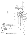
- Fig. 1 shows schematically a meter installation 1 at a not shown here Process management of a process plant, also not shown.
- the measuring device installation 1 comprises a medium-loaded measuring line 2 between the process line, not shown here, and a pressure transmitter 3 as a measuring device, the pressure transmitter 3 cantilevered from the with the process line connected measuring line 2 is held.
- the pressure transmitter 3 is here in a without aids, such as z. B. a ladder unreachable height cantilevered on the process line of Process equipment attached.
- shut-off 4 the here, for example can be designed as a plug cock or ball valve. From this obturator 4 starting is a drive line 5 down to a suitable connection height led to the bottom area 6.
- Both the lines 7,8 of the tester line 21 and the drive line 5 are here for example designed as hose lines.
- the pressure transmitter 3 To the pressure transmitter 3 maintenance, such. B. a rinse or a Being able to carry out calibration from the ground is the pressure transmitter 3 first disconnect from the process line, not shown here.
- the obturator 4 is to be brought into a shut-off position.
- movable Actuator 12 From a worker 11 is this trained as a mobile device and movable Actuator 12, which is exemplified here as a pneumatic actuator is coupled via a connecting line 13 to the drive line 5, as in the schematic representation of FIG. 1 by the arrow 14 only is shown extremely exemplarily.
- the pneumatic actuator 15 includes an air compressor 15 of the actuated pneumatic actuator 12, the obturator 4 applied via the drive line 5 with compressed air and this from a passage position, not shown here in a shut-off position transferred.
- the obturator is biased here by way of example in the passage position, which is not shown here, so that the transfer into the Blocking position against this bias occurs.
- test device 16 of the actuator 12 on a jointly movable cars can also provide all other mobile options be, so z. B. a separately movable to the actuator 12 tester or a portable tester, which is not discussed here in detail becomes.
- the tester 16 again from the Lines 7, 8 of the tester line 21 are easily decoupled, resulting in training as a quick-release connection particularly easy to perform is.
- the actuator 12 again in its unactuated Position are brought, so that the obturator 4 is no longer is acted upon by the compressed air.
- the obturator 4 can then by the previously mentioned bias in the passage position, z. Legs Spring preload, are automatically put back into the passage position, so that again a connection between the measuring line and the process line can be produced.
- a provision in the passage position by means of Actuator 12 via the drive line 5 can be achieved by z.
- a further parallel line is provided, which may be the provision effected in the passage position.
- Fig. 2 is an alternative embodiment of a meter installation 22, which shows substantially the same structure as the meter installation 1 of Fig. 1.
- the obturator in this instrument installation 22 as Changeover member 23, z. B. in the manner of a 3/2-way cock, with the the lines 7, 8 of the tester line 21 and the drive line 5 are coupled are.
- the obturator can accordingly be moved into the shut-off position or into the passage position, as is well known, for. B. in conjunction with 3/2-way valves, so that will not be discussed further here.
- a switching device 23 is a particularly compact design possible.
Description
- Fig. 1
- eine schematische Darstellung einer ersten Ausführungsform der erfindungsgemäßen Messgeräteinstallation, und
- Fig. 2
- eine schematische Darstellung einer alternativen Ausführungsform einer erfindungsgemäßen Messgeräteinstallation.
Claims (18)
- Messgeräteinstallation an einer Prozessleitung einer Prozessanlage
mit wenigstens einer mediumbeaufschlagten Messleitung (2) zwischen der Prozessleitung und dem Messgerät (3), vorzugsweise einem Drucktransmitter oder einem Differenzdrucktransmitter, wobei das Messgerät (3) freitragend von der mit der Prozessleitung verbundenen wenigstens einen Messleitung (2) gehalten ist,
mit einem Absperrorgan (4; 23) zwischen dem Messgerät (3) und der Prozessleitung, das mittels einer Stelleinrichtung zwischen einer Durchgangsposition und einer Absperrposition verstellbar ist, und
mit einem mit dem Messgerät (3) koppelbaren Prüfgerät (16), mittels dem bei sich in der Absperrposition befindlichem Absperrorgan (4; 23) Wartungsarbeiten, vorzugsweise eine Spülung und/oder eine Kalibrierung, am Messgerät (3) durchführbar sind,
dadurch gekennzeichnet, dass das Prüfgerät (16) mit dem Messgerät (3) über wenigstens eine Prüfgeräte-Leitung (21) koppelbar ist dergestalt, dass das Prüfgerät (16) beabstandet und entfernt vom Messgerät (3) anordenbar und zur Durchführung der Wartungsarbeiten fernbedienbar ist, und
dass die Stelleinrichtung des Absperrorgans (4; 23) als Stellantrieb (12) ausgebildet ist, der mit dem Absperrorgan (4; 23) über wenigstens eine Antriebsleitung (5) koppelbar ist dergestalt, dass der Stellantrieb (12) beabstandet und entfernt vom Absperrorgan (4; 23) anordenbar und zur Verstellung des Absperrorgans (4; 23) fernbedienbar ist. - Messgeräteinstallation nach Anspruch 1, dadurch gekennzeichnet, dass das Absperrorgan (4; 23) zu dessen Verstellung mittels dem Stellantrieb (12) über die Antriebsleitung (5) pneumatisch mit Druckluft als Arbeitsmedium oder hydraulisch mit einer Hydraulikflüssigkeit als Arbeitsmedium beaufschlagbar ist.
- Messgeräteinstallation nach Anspruch 2, dadurch gekennzeichnet, dass der Stellantrieb (12) eine Arbeitsmedium-Druckerhöhungseinheit (15) aufweist, mit der die Antriebsleitung (5) verbunden ist.
- Messgeräteinstallation nach Anspruch 3, dadurch gekennzeichnet, dass die Arbeitsmedium-Druckerhöhungseinheit im Falle eines pneumatischen Stellantriebs als Luftkompressor (15) und im Falle eines hydraulischen Stellantriebs als Hydraulik-Pumpe ausgebildet ist.
- Messgeräteinstallation nach einem der Ansprüche 1 bis 4, dadurch gekennzeichnet, dass das Absperrorgan (4; 23) in einer Grundstellung bei unbetätigtem Stellantrieb (12) in die Durchgangsposition vorgespannt, vorzugsweise federvorgespannt, ist, und
dass das Absperrorgan (4; 23) bei einer Betätigung des Stellantriebs (12) entgegen die Vorspannung in die Absperrposition überführbar ist. - Messgeräteinstallation nach einem der Ansprüche 1 bis 4, dadurch gekennzeichnet, dass die Antriebsleitung zwei separate Leitungen umfasst, von denen eine erste Leitung so mit dem Absperrorgan gekoppelt ist, dass über diese bei einer entsprechenden Ansteuerung nur ein Überführen des Absperrorgans in die Absperrposition erfolgt und von denen eine zweite Leitung so mit dem Absperrorgan gekoppelt ist, dass über diese bei einer entsprechenden Ansteuerung nur ein Überführen des Absperrorgans in die Durchgangsposition erfolgt.
- Messgeräteinstallation nach einem der Ansprüche 1 bis 6, dadurch gekennzeichnet, dass das Absperrorgan (4) ein Kugelhahn oder ein Kükenhahn ist.
- Messgeräteinstallation nach einem der Ansprüche 1 bis 6, dadurch gekennzeichnet, dass das Absperrorgan als Umschaltorgan (23), vorzugsweise als Wegehahn, höchst bevorzugt als 3/2-Wegehahn, ausgebildet ist, mit dem die wenigstens eine Prüfgeräte-Leitung (21) und die wenigstens eine Antriebsleitung (5) gekoppelt ist.
- Messgeräteinstallation nach einem der Ansprüche 1 bis 8, dadurch gekennzeichnet, dass das Messgerät über wenigstens eine Zusatz-Spülleitung mit einer Zusatz-Spüleinrichtung koppelbar ist dergestalt, dass die Zusatz-Spüleinrichtung beabstandet und entfernt vom Messgerät anordenbar und zur Spülung des Messgeräts und/oder der wenigstens einen Prüfgeräte-Leitung und/oder der wenigstens einen Antriebsleitung fernbedienbar ist.
- Messgeräteinstallation nach einem der Ansprüche 1 bis 9, dadurch gekennzeichnet, dass die Prüfgeräte-Leitung (21) zur Spülung des Messgerätes (3) mit einem Spülmedium oder zur Kalibrierung des Messgerätes (3) mit einem Kalibriermedium beaufschlagbar ist.
- Messgeräteinstallation nach Anspruch 10, dadurch gekennzeichnet, dass die Prüfgeräte-Leitung (21) wenigstens zur Spülung des Messgerätes (3) eine Zuführleitung (7) zur Zuführung des Spülmediums zum Messgerät (3) sowie eine Abführleitung (8) für das Spülmedium vom Messgerät (3) weg aufweist.
- Messgeräteinstallation nach Anspruch 11, dadurch gekennzeichnet, dass die Abführleitung (8) im Falle einer Kalibrierung eine zweite Zuführleitung für das Kalibriermedium zum Messgerät (3) bildet.
- Messgeräteinstallation nach einem der Ansprüche 1 bis 12, dadurch gekennzeichnet, dass das Prüfgerät (16) eine Prüfgeräte-Druckerhöhungseinheit (20), vorzugsweise einen Kompressor, aufweist.
- Messgeräteinstallation nach einem der Ansprüche 1 bis 13, dadurch gekennzeichnet, dass das Prüfgerät (16) als mobile Einrichtung ausgebildet ist, die zu einem freien Ende der wenigstens einen Prüfgeräte-Leitung (21) transportierbar und/oder fahrbar ist, vorzugsweise automatisiert transportierbar und/oder fahrbar ist, und die mit dem freien Ende der Prüfgeräte-Leitung (21) verbindbar ist, vorzugsweise automatisiert verbindbar ist, wobei die Verbindung vorzugsweise als Schnellkupplungs-Verbindung ausgebildet ist.
- Messgeräteinstallation nach einem der Ansprüche 1 bis 14, dadurch gekennzeichnet, dass der Stellantrieb (12) als mobile Einrichtung ausgebildet ist, die zu einem freien Ende der wenigstens einen mit dem Absperrorgan (4; 23) gekoppelten Antriebsleitung (5) transportierbar und/oder fahrbar ist, vorzugsweise automatisiert transportierbar und/oder fahrbar ist, und die mit dem freien Ende der Antriebsleitung (5) verbindbar ist, vorzugsweise automatisiert verbindbar ist, wobei die Verbindung vorzugsweise als Schnellkupplungs-Verbindung ausgebildet ist.
- Messgeräteinstallation nach Anspruch 14 und Anspruch 15, dadurch gekennzeichnet, dass die freien Enden der Prüfgeräte-Leitung (21) und der Antriebsleitung (5) benachbart zueinander angeordnet sind dergestalt, dass das Prüfgerät (16) und der Stellantrieb (12) auf derselben mobilen Einrichtung anordenbar sind.
- Messgeräteinstallation nach einem der Ansprüche 1 bis 16, dadurch gekennzeichnet, dass das Messgerät (3) in einer ohne Hilfsmittel nicht erreichbaren Höhe freitragend an einer Prozessleitung einer Prozessanlage angebracht ist, und
dass die wenigstens eine Prüfgeräte-Leitung (21) vom Messgerät (3) weg sowie die wenigstens eine Antriebsleitung (5) vom Absperrorgan (4; 23) weg sowie gegebenenfalls wenigstens eine Zusatz-Spülleitung vom Messgerät (3) weg mit einem freien Ende nach unten, vorzugsweise bis in etwa in den Bodenbereich (6), geführt sind. - Messgeräteinstallation nach einem der Ansprüche 1 bis 17, dadurch gekennzeichnet, dass die Leitungen (5, 7, 8) als Schlauch- und/oder Rohrleitungen ausgebildet sind.
Priority Applications (2)
| Application Number | Priority Date | Filing Date | Title |
|---|---|---|---|
| DE50106641T DE50106641D1 (de) | 2001-09-21 | 2001-09-21 | Messgeräteinstallation an einer Prozessleitung einer Prozessanlage |
| EP20010122794 EP1296123B1 (de) | 2001-09-21 | 2001-09-21 | Messgeräteinstallation an einer Prozessleitung einer Prozessanlage |
Applications Claiming Priority (1)
| Application Number | Priority Date | Filing Date | Title |
|---|---|---|---|
| EP20010122794 EP1296123B1 (de) | 2001-09-21 | 2001-09-21 | Messgeräteinstallation an einer Prozessleitung einer Prozessanlage |
Publications (2)
| Publication Number | Publication Date |
|---|---|
| EP1296123A1 EP1296123A1 (de) | 2003-03-26 |
| EP1296123B1 true EP1296123B1 (de) | 2005-06-29 |
Family
ID=8178702
Family Applications (1)
| Application Number | Title | Priority Date | Filing Date |
|---|---|---|---|
| EP20010122794 Expired - Lifetime EP1296123B1 (de) | 2001-09-21 | 2001-09-21 | Messgeräteinstallation an einer Prozessleitung einer Prozessanlage |
Country Status (2)
| Country | Link |
|---|---|
| EP (1) | EP1296123B1 (de) |
| DE (1) | DE50106641D1 (de) |
Families Citing this family (2)
| Publication number | Priority date | Publication date | Assignee | Title |
|---|---|---|---|---|
| WO2011009475A1 (de) * | 2009-07-24 | 2011-01-27 | Siemens Aktiengesellschaft | Kalibriervorrichtung für einen differenzdruckmessumformer |
| WO2011009476A1 (de) * | 2009-07-24 | 2011-01-27 | Siemens Aktiengesellschaft | Kalibriervorrichtung für einen druckmessumformer |
Family Cites Families (3)
| Publication number | Priority date | Publication date | Assignee | Title |
|---|---|---|---|---|
| US5069072A (en) * | 1990-07-26 | 1991-12-03 | Woodhead Industries, Inc. | Connector module for transducer |
| US5502659A (en) * | 1994-06-06 | 1996-03-26 | Endress+Hauser, Inc. | Method and apparatus for calibrating moisture sensors |
| DE19921172C1 (de) * | 1999-05-07 | 2000-11-16 | Martin Hess | Drucktransmitterinstallation an einer Prozeßleitung einer Prozeßanlage |
-
2001
- 2001-09-21 EP EP20010122794 patent/EP1296123B1/de not_active Expired - Lifetime
- 2001-09-21 DE DE50106641T patent/DE50106641D1/de not_active Expired - Lifetime
Also Published As
| Publication number | Publication date |
|---|---|
| EP1296123A1 (de) | 2003-03-26 |
| DE50106641D1 (de) | 2005-08-04 |
Similar Documents
| Publication | Publication Date | Title |
|---|---|---|
| DE10042488B4 (de) | Vakuumerzeugungseinheit | |
| DE4214320C1 (de) | ||
| EP2295186B1 (de) | Schutzgasschweiß-Steuerungsvorrichtung | |
| DE3806998A1 (de) | Steuereinheit fuer unter druck stehende gase | |
| DE2612562A1 (de) | Sicherheitssperrventil | |
| DE102011003194A1 (de) | Rolleneinrichtung | |
| EP2180226A1 (de) | Modulares Fluidverteilsystem | |
| EP1296123B1 (de) | Messgeräteinstallation an einer Prozessleitung einer Prozessanlage | |
| DE19819716C1 (de) | Druckmittelzange | |
| DE60213001T2 (de) | Gerät zum verteilen von flüssigkeiten und grundplatte | |
| DE10248319B4 (de) | Ventileinheit | |
| DE4110375A1 (de) | Verfahren und vorrichtung zum pruefen von rohrleitungen | |
| WO2002033133A1 (de) | Verfahren und vorrichtung zum gluehen von rohren | |
| EP1731393B2 (de) | Luftaufbereitungsanlage und Feststellbremsventilmodul für eine Nutzfahrzeugbremsanlage | |
| DE10058145B4 (de) | Zylindervorrichtung | |
| EP2950975B1 (de) | Vorrichtung zum zuführen von kleinteilen an einbauorten | |
| DE19536219C1 (de) | Hydraulikleitung mit integriertem, drucklosem Rücklauf | |
| DE2809065A1 (de) | Fluiden-pruefvorrichtung | |
| DE102016012867B4 (de) | Vorrichtung zur Verbindung eines Rohrs mit einem ansteckbaren Steckkörper | |
| DE4210790C2 (de) | ||
| EP2984446A1 (de) | Vorrichtung zur pneumatischen objektvermessung | |
| DE10348806B3 (de) | Hochdruckwasserstrahl-Anlage mit Prüfdüse | |
| EP1116859B1 (de) | Werkzeug zum Zusammenfügen und/oder Trennen von Rohren | |
| AT509195B1 (de) | Verfahren zum verbinden eines endabschnitts einer leitung für flüssige oder gasförmige medien mit einem steckverbinder | |
| DE3240900C1 (de) | Kupplung für hydrauliche oder pneumatische Druckleitungen |
Legal Events
| Date | Code | Title | Description |
|---|---|---|---|
| PUAI | Public reference made under article 153(3) epc to a published international application that has entered the european phase |
Free format text: ORIGINAL CODE: 0009012 |
|
| AK | Designated contracting states |
Designated state(s): AT BE CH CY DE DK ES FI FR GB GR IE IT LI LU MC NL PT SE TR Kind code of ref document: A1 Designated state(s): AT BE CH CY DE DK ES FI FR GB GR IE IT LI LU MC NL PT SE TR |
|
| AX | Request for extension of the european patent |
Extension state: AL LT LV MK RO SI |
|
| 17P | Request for examination filed |
Effective date: 20030830 |
|
| AKX | Designation fees paid |
Designated state(s): DE FR |
|
| GRAP | Despatch of communication of intention to grant a patent |
Free format text: ORIGINAL CODE: EPIDOSNIGR1 |
|
| GRAS | Grant fee paid |
Free format text: ORIGINAL CODE: EPIDOSNIGR3 |
|
| GRAA | (expected) grant |
Free format text: ORIGINAL CODE: 0009210 |
|
| AK | Designated contracting states |
Kind code of ref document: B1 Designated state(s): DE FR |
|
| REF | Corresponds to: |
Ref document number: 50106641 Country of ref document: DE Date of ref document: 20050804 Kind code of ref document: P |
|
| PLBE | No opposition filed within time limit |
Free format text: ORIGINAL CODE: 0009261 |
|
| STAA | Information on the status of an ep patent application or granted ep patent |
Free format text: STATUS: NO OPPOSITION FILED WITHIN TIME LIMIT |
|
| 26N | No opposition filed |
Effective date: 20060330 |
|
| EN | Fr: translation not filed | ||
| PG25 | Lapsed in a contracting state [announced via postgrant information from national office to epo] |
Ref country code: FR Free format text: LAPSE BECAUSE OF FAILURE TO SUBMIT A TRANSLATION OF THE DESCRIPTION OR TO PAY THE FEE WITHIN THE PRESCRIBED TIME-LIMIT Effective date: 20060825 |
|
| PG25 | Lapsed in a contracting state [announced via postgrant information from national office to epo] |
Ref country code: FR Free format text: LAPSE BECAUSE OF FAILURE TO SUBMIT A TRANSLATION OF THE DESCRIPTION OR TO PAY THE FEE WITHIN THE PRESCRIBED TIME-LIMIT Effective date: 20050930 |
|
| PG25 | Lapsed in a contracting state [announced via postgrant information from national office to epo] |
Ref country code: FR Free format text: LAPSE BECAUSE OF FAILURE TO SUBMIT A TRANSLATION OF THE DESCRIPTION OR TO PAY THE FEE WITHIN THE PRESCRIBED TIME-LIMIT Effective date: 20050629 |
|
| PGFP | Annual fee paid to national office [announced via postgrant information from national office to epo] |
Ref country code: DE Payment date: 20110901 Year of fee payment: 11 |
|
| PG25 | Lapsed in a contracting state [announced via postgrant information from national office to epo] |
Ref country code: DE Free format text: LAPSE BECAUSE OF NON-PAYMENT OF DUE FEES Effective date: 20130403 |
|
| REG | Reference to a national code |
Ref country code: DE Ref legal event code: R119 Ref document number: 50106641 Country of ref document: DE Effective date: 20130403 |