EP2815896B1 - Pneumatic motorcycle tire - Google Patents
Pneumatic motorcycle tire Download PDFInfo
- Publication number
- EP2815896B1 EP2815896B1 EP13748565.2A EP13748565A EP2815896B1 EP 2815896 B1 EP2815896 B1 EP 2815896B1 EP 13748565 A EP13748565 A EP 13748565A EP 2815896 B1 EP2815896 B1 EP 2815896B1
- Authority
- EP
- European Patent Office
- Prior art keywords
- groove
- tire
- rotation direction
- end portion
- tread
- Prior art date
- Legal status (The legal status is an assumption and is not a legal conclusion. Google has not performed a legal analysis and makes no representation as to the accuracy of the status listed.)
- Not-in-force
Links
Images
Classifications
-
- B—PERFORMING OPERATIONS; TRANSPORTING
- B60—VEHICLES IN GENERAL
- B60C—VEHICLE TYRES; TYRE INFLATION; TYRE CHANGING; CONNECTING VALVES TO INFLATABLE ELASTIC BODIES IN GENERAL; DEVICES OR ARRANGEMENTS RELATED TO TYRES
- B60C11/00—Tyre tread bands; Tread patterns; Anti-skid inserts
- B60C11/03—Tread patterns
- B60C11/0302—Tread patterns directional pattern, i.e. with main rolling direction
-
- B—PERFORMING OPERATIONS; TRANSPORTING
- B60—VEHICLES IN GENERAL
- B60C—VEHICLE TYRES; TYRE INFLATION; TYRE CHANGING; CONNECTING VALVES TO INFLATABLE ELASTIC BODIES IN GENERAL; DEVICES OR ARRANGEMENTS RELATED TO TYRES
- B60C11/00—Tyre tread bands; Tread patterns; Anti-skid inserts
- B60C11/03—Tread patterns
- B60C11/0304—Asymmetric patterns
-
- B—PERFORMING OPERATIONS; TRANSPORTING
- B60—VEHICLES IN GENERAL
- B60C—VEHICLE TYRES; TYRE INFLATION; TYRE CHANGING; CONNECTING VALVES TO INFLATABLE ELASTIC BODIES IN GENERAL; DEVICES OR ARRANGEMENTS RELATED TO TYRES
- B60C11/00—Tyre tread bands; Tread patterns; Anti-skid inserts
- B60C11/03—Tread patterns
- B60C11/032—Patterns comprising isolated recesses
-
- B—PERFORMING OPERATIONS; TRANSPORTING
- B60—VEHICLES IN GENERAL
- B60C—VEHICLE TYRES; TYRE INFLATION; TYRE CHANGING; CONNECTING VALVES TO INFLATABLE ELASTIC BODIES IN GENERAL; DEVICES OR ARRANGEMENTS RELATED TO TYRES
- B60C11/00—Tyre tread bands; Tread patterns; Anti-skid inserts
- B60C11/03—Tread patterns
- B60C11/12—Tread patterns characterised by the use of narrow slits or incisions, e.g. sipes
-
- B—PERFORMING OPERATIONS; TRANSPORTING
- B60—VEHICLES IN GENERAL
- B60C—VEHICLE TYRES; TYRE INFLATION; TYRE CHANGING; CONNECTING VALVES TO INFLATABLE ELASTIC BODIES IN GENERAL; DEVICES OR ARRANGEMENTS RELATED TO TYRES
- B60C11/00—Tyre tread bands; Tread patterns; Anti-skid inserts
- B60C11/03—Tread patterns
- B60C2011/0337—Tread patterns characterised by particular design features of the pattern
- B60C2011/0339—Grooves
- B60C2011/0374—Slant grooves, i.e. having an angle of about 5 to 35 degrees to the equatorial plane
- B60C2011/0376—Slant grooves, i.e. having an angle of about 5 to 35 degrees to the equatorial plane characterised by width
-
- B—PERFORMING OPERATIONS; TRANSPORTING
- B60—VEHICLES IN GENERAL
- B60C—VEHICLE TYRES; TYRE INFLATION; TYRE CHANGING; CONNECTING VALVES TO INFLATABLE ELASTIC BODIES IN GENERAL; DEVICES OR ARRANGEMENTS RELATED TO TYRES
- B60C11/00—Tyre tread bands; Tread patterns; Anti-skid inserts
- B60C11/03—Tread patterns
- B60C2011/0337—Tread patterns characterised by particular design features of the pattern
- B60C2011/0339—Grooves
- B60C2011/0381—Blind or isolated grooves
-
- B—PERFORMING OPERATIONS; TRANSPORTING
- B60—VEHICLES IN GENERAL
- B60C—VEHICLE TYRES; TYRE INFLATION; TYRE CHANGING; CONNECTING VALVES TO INFLATABLE ELASTIC BODIES IN GENERAL; DEVICES OR ARRANGEMENTS RELATED TO TYRES
- B60C2200/00—Tyres specially adapted for particular applications
- B60C2200/10—Tyres specially adapted for particular applications for motorcycles, scooters or the like
Definitions
- the present invention relates to a pneumatic motorcycle tire (hereinafter, also simply referred to as "tire"), and particularly, to a pneumatic motorcycle tire in which an arrangement condition of a groove which is formed on the surface of a tread portion is improved.
- Patent Document 1 discloses a technique of a pneumatic motorcycle tire whose rotation direction when mounted on a vehicle is designated, wherein a bent main groove composed of: a first groove extending toward a designated tire rotation direction inclined outside in the tread width direction in a contact region during straight running of a tread surface; and a second groove extending obliquely outside in the tread width direction from the end portion in the reverse rotation direction of a designated tire rotation direction of the first groove is provided, and the inclination angle of the first groove is defined as a predetermined angle.
- This technique is aimed at providing a pneumatic motorcycle tire in which both a grip performance with which secure and sporty running can be performed on a circuit or the like and a wet performance with which a secure running can be performed even on a public road are attained.
- Patent Document 1 Japanese Unexamined Patent Application Publication No. 2011-189805 (CLAIMS and the like)
- an object of the present invention is to solve the above-described problem, and to provide a pneumatic motorcycle tire in which, without compromising the stability during running, other performances such as light-weight are improved.
- the present inventor intensively studied to find that, by enhancing running performances including the stability by improving not the structure of a tire but the pattern structure on the surface of a tread portion of the tire, both the running performances and light-weight or the like can be attained, thereby completing the present invention.
- the present invention is a pneumatic rear motorcycle tire as claimed in claim 1.
- a groove width w A of the first groove is larger than a groove width w B of the second groove, and the range represented by the following expression: 1 ⁇ w A / w B ⁇ 2 is satisfied.
- an inclination angle ⁇ 1 with respect to the tire circumferential direction of the first groove is from 15° to 40°
- an inclination angle ⁇ 2 with respect to the tire circumferential direction of the second groove is from 15° to 40°.
- the tread width be TW
- the distance from the tire equator plane to the end portion outside in the tire width direction of the second groove be W 2
- the following expression: 0.1 ⁇ W 2 / TW ⁇ 0.3 is preferably satisfied.
- Fig. 1 is a partial development view illustrating a tread of one example of a pneumatic motorcycle tire of the present invention.
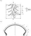
- Fig. 2 is a schematic cross section illustrating one example of a pneumatic motorcycle tire of the present invention.
- the pneumatic motorcycle tire of the present invention comprises a tread portion 1, and side wall portion 2 and bead portion 3 extending from both sides of the tread portion, and is one having a so-called directional pattern in which the rotation direction when mounted on a vehicle is designated.
- An arrow sign in Fig. 1 represents the rotation direction (designated rotation direction) when the tire is mounted on a vehicle.
- a groove in a direction along an input generated on a tire tread during running for efficiently utilizing a grip force generated on the surface of a tire during rolling. Since a driving wheel is at the rear of a motorcycle, a traction is generated on the rear tire when traveling straight and a lateral force is generated on the rear tire when turning; therefore, it is important to effectively arrange a groove in response to both the inputs. It is thus thought that it is effective to arrange a lug groove on a tread center portion in a direction approximately to the tire circumferential direction and to arrange on a tread shoulder portion a lug groove inclined in a direction approximately to the tire width direction.
- a tire tread is provided with a main groove 10 including two bending portions.
- a main groove 10 is composed of: a first groove 11 extending toward the designated tire rotation direction inclined outside in the tire width direction in a contact region during straight running; a second groove 12 extending from the end portion of the first groove 11 in the reverse rotation direction of the designated tire rotation direction toward the reverse rotation direction of the designated tire rotation direction inclined outside in the tire width direction; and a third groove 13 extending from the end portion of the second groove 12 in the reverse rotation direction of the designated tire rotation direction toward the reverse rotation direction of the designated tire rotation direction inclined outside in the tire width direction.
- the main grooves 10 are arranged at a predetermined interval in the tire circumferential direction alternately on one side and the other side of the surface of a tread portion bridging a tire equator plane CL such that they are at least overlapped when projected in the tire width direction, to form a pattern.
- both ends of the contact region in the tire width direction during straight running are each positioned at the middle point between the end portion outside in the tire width direction of the first groove 11 having a distance W 1 from the tire equator plane and the end portion outside in the tire width direction of the second groove 12 having a distance W 2 from the tire equator plane CL.
- the main groove is formed such that an inclination angle ⁇ 3 with respect to the tire circumferential direction of the third groove 13 is larger than an inclination angle ⁇ 2 with respect to the tire circumferential direction of the second groove 12.
- the main groove 10 forms approximately an C-shape (or approximately an inversed C-shape) as a whole.
- each of the inclination angles ⁇ 1 , ⁇ 3 of the first, third grooves 11, 13 with respect to the tire circumferential direction is an angle formed by a line connecting the terminal position of each groove and the center position of the bending point in the groove width, and the tire circumferential direction.
- the inclination angle ⁇ 2 of the second groove 12 with respect to the tire circumferential direction is an angle formed by a line connecting between the center positions of bending points in the groove width, and the tire circumferential direction.
- the groove width of each groove means a groove width measured along the direction orthogonal to the direction along the groove.
- the present invention by providing such a main groove 10, the following effects can be obtained. Specifically, regarding a tread center portion in the vicinity of the contact region during straight running, by arranging the first groove 11 and second groove 12 bending toward the inside of the tire, a ground contact area is increased by appropriately reducing the off-plane flexural rigidity to improve the grounding property, thereby enhancing the endurance against a disturbance input. By setting the inclination angles of the first groove 11 and second groove 12 relatively small, an input generated on a tread in a front-rear direction at the time of driving is not inhibited, thereby sufficiently securing a drainability.
- the third groove 13 whose inclination angle with respect to the tire circumferential direction is larger than that of the second groove 12 is arranged.
- the third groove 13 whose inclination angle is closer to the tire width direction following an input during turning, deformation of a land portion due to an external force during turning of a vehicle is restrained and a ground contact surface is secured, thereby improving the running performance to a lateral force. From a similar reason to that of the tread center portion, the drainability in this region can be improved.
- the direction of the groove does not follow the lateral force, and therefore a desired grip performance is not obtained.
- a pneumatic motorcycle tire in which grip performance, wet performance, or the like can be improved while securing stability during running without compromising light-weight since change of the structure of a tire is not involved, and safe running is made possible on a variety of road surfaces can be attained.
- contact region during straight running refers to a region which is a ground contact surface of a tire when a tire is subjected to a straight running under a prescribed load in a state in which the tire is mounted on a rim which is defined by an industrial standard which is effective in a region where the tire is produced and to be used and in which the tire is inflated to an inner pressure defined in the industrial standard.
- the above-mentioned industrial standard corresponds to JATMA (Japan Automobile Tyre Manufacturers Association, Inc.) YEAR BOOK in Japan, corresponds to ETRTO (European Tyre and Rim Technical Organisation) STANDARD MANUAL in Europe, corresponds to TRA (THE TIRE and RIM ASSOCIATION INC.) YEARBOOK in the United States, and so on.
- the "designated tire rotation direction” refers to a direction which is designated to the rotation direction of a tire when the tire is mounted on a vehicle, which is the direction of the arrow in Fig. 1 .
- the "reverse rotation direction” refers to a backward direction when the designated tire rotation direction is set to a forward direction.
- first groove extends in a contact region during straight running
- 70% or larger of the groove area of the first groove 11 is in the contact region during straight running.
- Part of the first groove 11 may be arranged extending to a contact region on the outside of the contact region during straight running in the tire diameter direction.
- 80% or larger of the groove area of the second groove can be arranged in the contact region during straight running, and part of the second groove may be arranged extending to a contact region on the outside of the contact region in the tire diameter direction.
- the inclination angles ⁇ 1 and ⁇ 2 of the first groove 11 and second groove 12 with respect to the tire circumferential direction are preferably set to the following ranges. That is, the inclination angle ⁇ 1 is suitably from 15° to 40°, and the inclination angle ⁇ 2 is suitably from 15° to 40°.
- the inclination angle is smaller than the above-described range, an effect of improving the stability due to the improvement of the grounding property is small.
- the angle is larger than the above-described range, deterioration of grip performance is notable since an input by driving force is inhibited.
- the inclination angle ⁇ 1 is preferably set to 35° or smaller since, when the angle is above 35°, deterioration of wet performance due to deterioration of drainability is notable.
- the third groove 13 which is arranged on the tread shoulder side is preferably in a direction following a lateral force, and the inclination angle ⁇ 3 of the groove with respect to the tire circumferential direction is from 50° to 80°.
- the inclination angle ⁇ 3 is smaller than the above-described range, grip performance is deteriorated since an input is inhibited.
- the angle is larger than the above-described range, deterioration of wet performance due to deterioration of drainability is notable.
- the main groove 10 formed by these three grooves 11 to 13 may be interrupted at least at one portion.
- the interrupted portion is preferably provided on the third groove 13 portion.
- the connecting portions of the first to third grooves are preferably formed in a curved shape as illustrated in the drawing. In the case of the continuous main groove 10 which is formed by connecting the first groove 11, second groove 12, and third groove 13 together, the drainability is improved since the main groove 10 is continuous as a drainage route, and as the result, the wet performance of a tire is improved.
- the groove width w A of the first groove 11 is preferably set a little larger than the groove width w B of the second groove 12, and specifically, is preferably set such that the range represented by the following expression: 1 ⁇ w A / w B ⁇ 2 is satisfied.
- the ratio w A /w B is above 2, an influence of deterioration of grip performance due to deterioration of rigidity is notable.
- the main groove 10 is preferably arranged separated from the tire equator plane CL. This also means that, in the present invention, there preferably is no circumferential direction groove extending in the tire circumferential direction on the tire equator.
- the first groove 11 is preferably arranged in a range satisfying the following expression: 0.05 ⁇ W 1 / TW ⁇ 0.2, letting the tread width be TW, and the distance from the tire equator plane to the outside end portion of the first groove 11 in the tire width direction be W 1 .
- the connecting portion of the second groove 12 and third groove 13 is preferably set in the following range. Specifically, letting the tread width be TW, and the distance from the tire equator plane CL to the outside end portion of the second groove 12 in the tire width direction be W 2 , the following expression: 0.1 ⁇ W 2 / TW ⁇ 0.3 is satisfied. When the ratio W 2 /TW is below 0.1, grip performance during straight running deteriorates; when the ratio is larger than 0.3, grip performance during turning deteriorates.
- auxiliary groove other than the main groove 10 can be appropriately arranged.
- auxiliary grooves 14, 15 are arranged outside, in the tire width direction, from the end portion of the second groove 12 in the reverse rotation direction of the designated tire rotation direction.
- auxiliary grooves 14, 15 other than the main groove 10 which are arranged to secure wet performance are preferably arranged separated from each other by a distance at least 0.14 times the tread width TW.
- the lateral rigidity deteriorates causing deterioration of the stability.
- This in turns means that there is no groove other than the second groove 12 in a region from the outside end portion of the first groove 11 in the tire width direction to the outside end portion of the second groove 12 in the tire width direction.
- the arrangement pitch of the main grooves 10, in particular, of the main grooves 10 and auxiliary grooves is not particularly restricted, and may be approximately 1/11 to 1/13 of the total circumferential length of a tire.
- the positions of the main groove 10, in particular, the main groove 10 and auxiliary grooves in the tire circumferential direction are arranged on the surface of the tread portion alternately on one side and the other side across the tire equator plane CL, or arranged shifted by 1/2 of the arrangement pitch.
- a tire of the present invention comprises: a carcass 5 which is arranged bridging between a pair of bead cores 4 each embedded in bead portion 3 and reinforces each portions; and a belt 6 which is arranged on the outer periphery thereof and reinforces the tread portion 1.
- a belt 6 may be composed of two or more inclined belt layers which are arranged such that cord directions are crossed with each other between the layers, or may be composed of one or more spiral belt layers in which the cord direction is substantially in the tire circumferential direction.
- the present invention is useful for a rear tire for motorcycle, and can be applied to either a radial structure tire or a bias structure tire.
- Example 10 is not according to the present invention.
- a rear tire for motorcycle having a tire size of MCR180/SSZR17M/C with a directional pattern of a type illustrated in Fig. 1 was manufactured by changing the values of inclination angle, W 1 /TW, W 2 /TW and w A /w B of first to third grooves.
- a spiral belt layer whose cord direction is substantially in the tire circumferential direction was arranged as one layer.
- Each obtained test tire was mounted on a large-size motorcycle of 1250 cc, and the running stability, grip performance and wet performance were evaluated by feeling evaluation in a real vehicle test.
- As a front tire a commercially available tire with a size of MCR120/70ZR17M/C was used. The results were indicated as indices taking 100 as a normal level. For each item, when the value is large, the performance is high, which is preferable. For each performance, a point within ⁇ 3 was regarded to be in a tolerance range (in a similar level). The results are listed on the Table below in combination.
- Example 3 shows that, in Example 3 in which the inclination angle of the first groove is small, the stability tends to be low and shows that, in Example 4 in which the inclination angle of the first groove is large, grip performance and wet performance tend to be deteriorated. Further, it is shown that, also in Example 6 in which the value of W 2 /TW is small and in Example 8 in which the value of w A /w B is large, grip performance and wet performance tend to be deteriorated.
Landscapes
- Engineering & Computer Science (AREA)
- Mechanical Engineering (AREA)
- Tires In General (AREA)
Applications Claiming Priority (2)
| Application Number | Priority Date | Filing Date | Title |
|---|---|---|---|
| JP2012028548A JP5890192B2 (ja) | 2012-02-13 | 2012-02-13 | 自動二輪車用空気入りタイヤ |
| PCT/JP2013/052688 WO2013121945A1 (ja) | 2012-02-13 | 2013-02-06 | 自動二輪車用空気入りタイヤ |
Publications (3)
| Publication Number | Publication Date |
|---|---|
| EP2815896A1 EP2815896A1 (en) | 2014-12-24 |
| EP2815896A4 EP2815896A4 (en) | 2015-11-25 |
| EP2815896B1 true EP2815896B1 (en) | 2018-05-30 |
Family
ID=48984058
Family Applications (1)
| Application Number | Title | Priority Date | Filing Date |
|---|---|---|---|
| EP13748565.2A Not-in-force EP2815896B1 (en) | 2012-02-13 | 2013-02-06 | Pneumatic motorcycle tire |
Country Status (5)
| Country | Link |
|---|---|
| US (1) | US10836214B2 (ja) |
| EP (1) | EP2815896B1 (ja) |
| JP (1) | JP5890192B2 (ja) |
| CN (1) | CN104114381B (ja) |
| WO (1) | WO2013121945A1 (ja) |
Families Citing this family (4)
| Publication number | Priority date | Publication date | Assignee | Title |
|---|---|---|---|---|
| JP6514471B2 (ja) * | 2014-09-26 | 2019-05-15 | 株式会社ブリヂストン | 自動二輪車用タイヤ |
| JP6503257B2 (ja) * | 2015-07-31 | 2019-04-17 | 株式会社ブリヂストン | 自動二輪車用タイヤ |
| JP7310174B2 (ja) * | 2019-03-05 | 2023-07-19 | 住友ゴム工業株式会社 | タイヤ |
| US20230339269A1 (en) * | 2019-09-24 | 2023-10-26 | Bridgestone Corporation | Motorbike tire |
Family Cites Families (15)
| Publication number | Priority date | Publication date | Assignee | Title |
|---|---|---|---|---|
| GB2114069B (en) * | 1982-02-01 | 1985-09-18 | Avon Tyres Ltd | Motorcycle tyre tread |
| JPS59179407A (ja) * | 1983-03-30 | 1984-10-12 | Yokohama Rubber Co Ltd:The | 二輪自動車用空気入りラジアルタイヤ |
| JPS63116907A (ja) * | 1986-11-05 | 1988-05-21 | Bridgestone Corp | 二輪車用空気入りタイヤの装着方法 |
| JPH05201207A (ja) * | 1992-01-27 | 1993-08-10 | Bridgestone Corp | モーターサイクル用空気入りタイヤ |
| AU116918S (en) * | 1992-04-03 | 1993-04-28 | Sumitomo Rubber Ind | A tyre |
| JP3495593B2 (ja) * | 1998-04-07 | 2004-02-09 | 住友ゴム工業株式会社 | 自動二輪車前輪用タイヤ |
| ATE236800T1 (de) * | 1998-11-19 | 2003-04-15 | Pirelli | Reifen für fahrzeugräder |
| JP4723310B2 (ja) * | 2005-08-12 | 2011-07-13 | 住友ゴム工業株式会社 | 空気入りタイヤ |
| JP4234762B1 (ja) * | 2007-08-22 | 2009-03-04 | 住友ゴム工業株式会社 | 自動二輪車用タイヤとその製造方法 |
| JP4685922B2 (ja) | 2008-12-26 | 2011-05-18 | 住友ゴム工業株式会社 | 空気入りタイヤ |
| JP4825289B2 (ja) * | 2009-08-26 | 2011-11-30 | 住友ゴム工業株式会社 | 空気入りタイヤ |
| EP2485904B1 (en) * | 2009-10-07 | 2017-05-03 | Pirelli Tyre S.p.A. | Motorcycle tyres |
| USD637139S1 (en) * | 2010-03-04 | 2011-05-03 | Bridgestone Corporation | Motorcycle tire |
| JP5590927B2 (ja) * | 2010-03-12 | 2014-09-17 | 株式会社ブリヂストン | 自動二輪車用空気入りタイヤ |
| JP5452338B2 (ja) * | 2010-04-21 | 2014-03-26 | 住友ゴム工業株式会社 | 空気入りタイヤ |
-
2012
- 2012-02-13 JP JP2012028548A patent/JP5890192B2/ja not_active Expired - Fee Related
-
2013
- 2013-02-06 EP EP13748565.2A patent/EP2815896B1/en not_active Not-in-force
- 2013-02-06 WO PCT/JP2013/052688 patent/WO2013121945A1/ja active Application Filing
- 2013-02-06 US US14/377,912 patent/US10836214B2/en active Active
- 2013-02-06 CN CN201380008988.XA patent/CN104114381B/zh not_active Expired - Fee Related
Non-Patent Citations (2)
| Title |
|---|
| ANONIMOUS: "120-70-17 Dunlop Sportmax II D204", 31 July 2006 (2006-07-31), XP055316145, Retrieved from the Internet <URL:http://thumbs2.picclick.com/d/l400/pict/271920096941_/120-70-17-Dunlop-Sportmax-II-D204.jpg> [retrieved on 20161103] * |
| DUNLOP: "Technische Informationen zur Ausrüstung von Motorrädern und Rollern", 1 July 2006 (2006-07-01), XP055316130, Retrieved from the Internet <URL:http://www.dunlop.eu/dunlop_atde/Images/Technical_Service_MC_german_(MS_1_2006)_1_tcm537-18088.pdf> [retrieved on 20161103] * |
Also Published As
| Publication number | Publication date |
|---|---|
| EP2815896A1 (en) | 2014-12-24 |
| US10836214B2 (en) | 2020-11-17 |
| CN104114381A (zh) | 2014-10-22 |
| US20140360637A1 (en) | 2014-12-11 |
| EP2815896A4 (en) | 2015-11-25 |
| CN104114381B (zh) | 2017-10-24 |
| WO2013121945A1 (ja) | 2013-08-22 |
| JP5890192B2 (ja) | 2016-03-22 |
| JP2013163488A (ja) | 2013-08-22 |
Similar Documents
| Publication | Publication Date | Title |
|---|---|---|
| EP2792505A1 (en) | Pneumatic tire | |
| WO2015178442A1 (ja) | 空気入りタイヤ | |
| US10500901B2 (en) | Motorcycle pneumatic tire | |
| JP5590927B2 (ja) | 自動二輪車用空気入りタイヤ | |
| EP3069901B1 (en) | Motorcycle tire | |
| EP2664465A1 (en) | Pneumatic tire for running on rough terrain | |
| EP2639083B1 (en) | Motorcycle tire | |
| JP2008126716A (ja) | 空気入りラジアルタイヤ | |
| JP5596580B2 (ja) | 自動二輪車用空気入りタイヤ | |
| EP2815896B1 (en) | Pneumatic motorcycle tire | |
| EP2815897B1 (en) | Pneumatic motorcycle tire | |
| EP2543522B1 (en) | Two-wheeled automotive vehicle tire | |
| US20130292017A1 (en) | Pnuematic tire | |
| EP2732984B1 (en) | Pneumatic radial tire | |
| JP2007022374A (ja) | 自動二輪車用空気入りラジアルタイヤ | |
| JPH07285302A (ja) | 空気入りタイヤ | |
| JP4758144B2 (ja) | 空気入りタイヤ | |
| JP2009029211A (ja) | 自動二輪車用空気入りタイヤ | |
| EP3666552B1 (en) | Tyre | |
| JP5676024B2 (ja) | 自動二輪車用空気入りタイヤ | |
| EP3199374B1 (en) | Motorcycle tire | |
| WO2012005248A1 (ja) | 自動二輪車用空気入りタイヤ | |
| JP2009051428A (ja) | 自動二輪車用タイヤ対 | |
| JP2010116058A (ja) | 二輪車用空気入りタイヤ | |
| JP2021084451A (ja) | バイアスタイヤ |
Legal Events
| Date | Code | Title | Description |
|---|---|---|---|
| PUAI | Public reference made under article 153(3) epc to a published international application that has entered the european phase |
Free format text: ORIGINAL CODE: 0009012 |
|
| 17P | Request for examination filed |
Effective date: 20140911 |
|
| AK | Designated contracting states |
Kind code of ref document: A1 Designated state(s): AL AT BE BG CH CY CZ DE DK EE ES FI FR GB GR HR HU IE IS IT LI LT LU LV MC MK MT NL NO PL PT RO RS SE SI SK SM TR |
|
| AX | Request for extension of the european patent |
Extension state: BA ME |
|
| DAX | Request for extension of the european patent (deleted) | ||
| RA4 | Supplementary search report drawn up and despatched (corrected) |
Effective date: 20151028 |
|
| RIC1 | Information provided on ipc code assigned before grant |
Ipc: B60C 11/117 20060101ALI20151022BHEP Ipc: B60C 11/04 20060101ALI20151022BHEP Ipc: B60C 11/03 20060101AFI20151022BHEP |
|
| REG | Reference to a national code |
Ref country code: DE Ref legal event code: R079 Ref document number: 602013038175 Country of ref document: DE Free format text: PREVIOUS MAIN CLASS: B60C0011040000 Ipc: B60C0011030000 |
|
| STAA | Information on the status of an ep patent application or granted ep patent |
Free format text: STATUS: EXAMINATION IS IN PROGRESS |
|
| RIC1 | Information provided on ipc code assigned before grant |
Ipc: B60C 11/03 20060101AFI20161018BHEP Ipc: B60C 11/04 20060101ALI20161018BHEP Ipc: B60C 11/117 20060101ALI20161018BHEP |
|
| 17Q | First examination report despatched |
Effective date: 20161109 |
|
| GRAP | Despatch of communication of intention to grant a patent |
Free format text: ORIGINAL CODE: EPIDOSNIGR1 |
|
| STAA | Information on the status of an ep patent application or granted ep patent |
Free format text: STATUS: GRANT OF PATENT IS INTENDED |
|
| INTG | Intention to grant announced |
Effective date: 20171205 |
|
| GRAS | Grant fee paid |
Free format text: ORIGINAL CODE: EPIDOSNIGR3 |
|
| GRAA | (expected) grant |
Free format text: ORIGINAL CODE: 0009210 |
|
| STAA | Information on the status of an ep patent application or granted ep patent |
Free format text: STATUS: THE PATENT HAS BEEN GRANTED |
|
| AK | Designated contracting states |
Kind code of ref document: B1 Designated state(s): AL AT BE BG CH CY CZ DE DK EE ES FI FR GB GR HR HU IE IS IT LI LT LU LV MC MK MT NL NO PL PT RO RS SE SI SK SM TR |
|
| REG | Reference to a national code |
Ref country code: GB Ref legal event code: FG4D |
|
| REG | Reference to a national code |
Ref country code: CH Ref legal event code: EP |
|
| REG | Reference to a national code |
Ref country code: AT Ref legal event code: REF Ref document number: 1003221 Country of ref document: AT Kind code of ref document: T Effective date: 20180615 |
|
| REG | Reference to a national code |
Ref country code: IE Ref legal event code: FG4D |
|
| REG | Reference to a national code |
Ref country code: DE Ref legal event code: R096 Ref document number: 602013038175 Country of ref document: DE |
|
| REG | Reference to a national code |
Ref country code: NL Ref legal event code: MP Effective date: 20180530 |
|
| REG | Reference to a national code |
Ref country code: LT Ref legal event code: MG4D |
|
| PG25 | Lapsed in a contracting state [announced via postgrant information from national office to epo] |
Ref country code: SE Free format text: LAPSE BECAUSE OF FAILURE TO SUBMIT A TRANSLATION OF THE DESCRIPTION OR TO PAY THE FEE WITHIN THE PRESCRIBED TIME-LIMIT Effective date: 20180530 Ref country code: ES Free format text: LAPSE BECAUSE OF FAILURE TO SUBMIT A TRANSLATION OF THE DESCRIPTION OR TO PAY THE FEE WITHIN THE PRESCRIBED TIME-LIMIT Effective date: 20180530 Ref country code: CY Free format text: LAPSE BECAUSE OF FAILURE TO SUBMIT A TRANSLATION OF THE DESCRIPTION OR TO PAY THE FEE WITHIN THE PRESCRIBED TIME-LIMIT Effective date: 20180530 Ref country code: BG Free format text: LAPSE BECAUSE OF FAILURE TO SUBMIT A TRANSLATION OF THE DESCRIPTION OR TO PAY THE FEE WITHIN THE PRESCRIBED TIME-LIMIT Effective date: 20180830 Ref country code: NO Free format text: LAPSE BECAUSE OF FAILURE TO SUBMIT A TRANSLATION OF THE DESCRIPTION OR TO PAY THE FEE WITHIN THE PRESCRIBED TIME-LIMIT Effective date: 20180830 Ref country code: FI Free format text: LAPSE BECAUSE OF FAILURE TO SUBMIT A TRANSLATION OF THE DESCRIPTION OR TO PAY THE FEE WITHIN THE PRESCRIBED TIME-LIMIT Effective date: 20180530 Ref country code: LT Free format text: LAPSE BECAUSE OF FAILURE TO SUBMIT A TRANSLATION OF THE DESCRIPTION OR TO PAY THE FEE WITHIN THE PRESCRIBED TIME-LIMIT Effective date: 20180530 |
|
| PG25 | Lapsed in a contracting state [announced via postgrant information from national office to epo] |
Ref country code: HR Free format text: LAPSE BECAUSE OF FAILURE TO SUBMIT A TRANSLATION OF THE DESCRIPTION OR TO PAY THE FEE WITHIN THE PRESCRIBED TIME-LIMIT Effective date: 20180530 Ref country code: GR Free format text: LAPSE BECAUSE OF FAILURE TO SUBMIT A TRANSLATION OF THE DESCRIPTION OR TO PAY THE FEE WITHIN THE PRESCRIBED TIME-LIMIT Effective date: 20180831 Ref country code: LV Free format text: LAPSE BECAUSE OF FAILURE TO SUBMIT A TRANSLATION OF THE DESCRIPTION OR TO PAY THE FEE WITHIN THE PRESCRIBED TIME-LIMIT Effective date: 20180530 Ref country code: RS Free format text: LAPSE BECAUSE OF FAILURE TO SUBMIT A TRANSLATION OF THE DESCRIPTION OR TO PAY THE FEE WITHIN THE PRESCRIBED TIME-LIMIT Effective date: 20180530 |
|
| REG | Reference to a national code |
Ref country code: AT Ref legal event code: MK05 Ref document number: 1003221 Country of ref document: AT Kind code of ref document: T Effective date: 20180530 |
|
| PG25 | Lapsed in a contracting state [announced via postgrant information from national office to epo] |
Ref country code: NL Free format text: LAPSE BECAUSE OF FAILURE TO SUBMIT A TRANSLATION OF THE DESCRIPTION OR TO PAY THE FEE WITHIN THE PRESCRIBED TIME-LIMIT Effective date: 20180530 |
|
| PG25 | Lapsed in a contracting state [announced via postgrant information from national office to epo] |
Ref country code: RO Free format text: LAPSE BECAUSE OF FAILURE TO SUBMIT A TRANSLATION OF THE DESCRIPTION OR TO PAY THE FEE WITHIN THE PRESCRIBED TIME-LIMIT Effective date: 20180530 Ref country code: CZ Free format text: LAPSE BECAUSE OF FAILURE TO SUBMIT A TRANSLATION OF THE DESCRIPTION OR TO PAY THE FEE WITHIN THE PRESCRIBED TIME-LIMIT Effective date: 20180530 Ref country code: EE Free format text: LAPSE BECAUSE OF FAILURE TO SUBMIT A TRANSLATION OF THE DESCRIPTION OR TO PAY THE FEE WITHIN THE PRESCRIBED TIME-LIMIT Effective date: 20180530 Ref country code: PL Free format text: LAPSE BECAUSE OF FAILURE TO SUBMIT A TRANSLATION OF THE DESCRIPTION OR TO PAY THE FEE WITHIN THE PRESCRIBED TIME-LIMIT Effective date: 20180530 Ref country code: AT Free format text: LAPSE BECAUSE OF FAILURE TO SUBMIT A TRANSLATION OF THE DESCRIPTION OR TO PAY THE FEE WITHIN THE PRESCRIBED TIME-LIMIT Effective date: 20180530 Ref country code: SK Free format text: LAPSE BECAUSE OF FAILURE TO SUBMIT A TRANSLATION OF THE DESCRIPTION OR TO PAY THE FEE WITHIN THE PRESCRIBED TIME-LIMIT Effective date: 20180530 Ref country code: DK Free format text: LAPSE BECAUSE OF FAILURE TO SUBMIT A TRANSLATION OF THE DESCRIPTION OR TO PAY THE FEE WITHIN THE PRESCRIBED TIME-LIMIT Effective date: 20180530 |
|
| PG25 | Lapsed in a contracting state [announced via postgrant information from national office to epo] |
Ref country code: IT Free format text: LAPSE BECAUSE OF FAILURE TO SUBMIT A TRANSLATION OF THE DESCRIPTION OR TO PAY THE FEE WITHIN THE PRESCRIBED TIME-LIMIT Effective date: 20180530 Ref country code: SM Free format text: LAPSE BECAUSE OF FAILURE TO SUBMIT A TRANSLATION OF THE DESCRIPTION OR TO PAY THE FEE WITHIN THE PRESCRIBED TIME-LIMIT Effective date: 20180530 |
|
| REG | Reference to a national code |
Ref country code: DE Ref legal event code: R097 Ref document number: 602013038175 Country of ref document: DE |
|
| PLBE | No opposition filed within time limit |
Free format text: ORIGINAL CODE: 0009261 |
|
| STAA | Information on the status of an ep patent application or granted ep patent |
Free format text: STATUS: NO OPPOSITION FILED WITHIN TIME LIMIT |
|
| 26N | No opposition filed |
Effective date: 20190301 |
|
| PG25 | Lapsed in a contracting state [announced via postgrant information from national office to epo] |
Ref country code: SI Free format text: LAPSE BECAUSE OF FAILURE TO SUBMIT A TRANSLATION OF THE DESCRIPTION OR TO PAY THE FEE WITHIN THE PRESCRIBED TIME-LIMIT Effective date: 20180530 |
|
| REG | Reference to a national code |
Ref country code: CH Ref legal event code: PL |
|
| GBPC | Gb: european patent ceased through non-payment of renewal fee |
Effective date: 20190206 |
|
| PG25 | Lapsed in a contracting state [announced via postgrant information from national office to epo] |
Ref country code: MC Free format text: LAPSE BECAUSE OF FAILURE TO SUBMIT A TRANSLATION OF THE DESCRIPTION OR TO PAY THE FEE WITHIN THE PRESCRIBED TIME-LIMIT Effective date: 20180530 Ref country code: LU Free format text: LAPSE BECAUSE OF NON-PAYMENT OF DUE FEES Effective date: 20190206 |
|
| REG | Reference to a national code |
Ref country code: BE Ref legal event code: MM Effective date: 20190228 |
|
| REG | Reference to a national code |
Ref country code: IE Ref legal event code: MM4A |
|
| PG25 | Lapsed in a contracting state [announced via postgrant information from national office to epo] |
Ref country code: AL Free format text: LAPSE BECAUSE OF FAILURE TO SUBMIT A TRANSLATION OF THE DESCRIPTION OR TO PAY THE FEE WITHIN THE PRESCRIBED TIME-LIMIT Effective date: 20180530 |
|
| PG25 | Lapsed in a contracting state [announced via postgrant information from national office to epo] |
Ref country code: LI Free format text: LAPSE BECAUSE OF NON-PAYMENT OF DUE FEES Effective date: 20190228 Ref country code: CH Free format text: LAPSE BECAUSE OF NON-PAYMENT OF DUE FEES Effective date: 20190228 |
|
| PG25 | Lapsed in a contracting state [announced via postgrant information from national office to epo] |
Ref country code: GB Free format text: LAPSE BECAUSE OF NON-PAYMENT OF DUE FEES Effective date: 20190206 Ref country code: IE Free format text: LAPSE BECAUSE OF NON-PAYMENT OF DUE FEES Effective date: 20190206 |
|
| PG25 | Lapsed in a contracting state [announced via postgrant information from national office to epo] |
Ref country code: BE Free format text: LAPSE BECAUSE OF NON-PAYMENT OF DUE FEES Effective date: 20190228 |
|
| PG25 | Lapsed in a contracting state [announced via postgrant information from national office to epo] |
Ref country code: TR Free format text: LAPSE BECAUSE OF FAILURE TO SUBMIT A TRANSLATION OF THE DESCRIPTION OR TO PAY THE FEE WITHIN THE PRESCRIBED TIME-LIMIT Effective date: 20180530 |
|
| PG25 | Lapsed in a contracting state [announced via postgrant information from national office to epo] |
Ref country code: PT Free format text: LAPSE BECAUSE OF FAILURE TO SUBMIT A TRANSLATION OF THE DESCRIPTION OR TO PAY THE FEE WITHIN THE PRESCRIBED TIME-LIMIT Effective date: 20181001 Ref country code: MT Free format text: LAPSE BECAUSE OF NON-PAYMENT OF DUE FEES Effective date: 20190206 |
|
| PGFP | Annual fee paid to national office [announced via postgrant information from national office to epo] |
Ref country code: FR Payment date: 20210225 Year of fee payment: 9 |
|
| PGFP | Annual fee paid to national office [announced via postgrant information from national office to epo] |
Ref country code: DE Payment date: 20210217 Year of fee payment: 9 |
|
| PG25 | Lapsed in a contracting state [announced via postgrant information from national office to epo] |
Ref country code: IS Free format text: LAPSE BECAUSE OF FAILURE TO SUBMIT A TRANSLATION OF THE DESCRIPTION OR TO PAY THE FEE WITHIN THE PRESCRIBED TIME-LIMIT Effective date: 20180930 |
|
| PG25 | Lapsed in a contracting state [announced via postgrant information from national office to epo] |
Ref country code: HU Free format text: LAPSE BECAUSE OF FAILURE TO SUBMIT A TRANSLATION OF THE DESCRIPTION OR TO PAY THE FEE WITHIN THE PRESCRIBED TIME-LIMIT; INVALID AB INITIO Effective date: 20130206 |
|
| PG25 | Lapsed in a contracting state [announced via postgrant information from national office to epo] |
Ref country code: MK Free format text: LAPSE BECAUSE OF FAILURE TO SUBMIT A TRANSLATION OF THE DESCRIPTION OR TO PAY THE FEE WITHIN THE PRESCRIBED TIME-LIMIT Effective date: 20180530 |
|
| REG | Reference to a national code |
Ref country code: DE Ref legal event code: R119 Ref document number: 602013038175 Country of ref document: DE |
|
| PG25 | Lapsed in a contracting state [announced via postgrant information from national office to epo] |
Ref country code: FR Free format text: LAPSE BECAUSE OF NON-PAYMENT OF DUE FEES Effective date: 20220228 |
|
| PG25 | Lapsed in a contracting state [announced via postgrant information from national office to epo] |
Ref country code: DE Free format text: LAPSE BECAUSE OF NON-PAYMENT OF DUE FEES Effective date: 20220901 |