EP2806245A1 - Dispositif de protection contre des projectiles - Google Patents
Dispositif de protection contre des projectiles Download PDFInfo
- Publication number
- EP2806245A1 EP2806245A1 EP14001632.0A EP14001632A EP2806245A1 EP 2806245 A1 EP2806245 A1 EP 2806245A1 EP 14001632 A EP14001632 A EP 14001632A EP 2806245 A1 EP2806245 A1 EP 2806245A1
- Authority
- EP
- European Patent Office
- Prior art keywords
- arrangement
- row
- bars
- profile bars
- profile
- Prior art date
- Legal status (The legal status is an assumption and is not a legal conclusion. Google has not performed a legal analysis and makes no representation as to the accuracy of the status listed.)
- Granted
Links
Images

Classifications
-
- F—MECHANICAL ENGINEERING; LIGHTING; HEATING; WEAPONS; BLASTING
- F41—WEAPONS
- F41H—ARMOUR; ARMOURED TURRETS; ARMOURED OR ARMED VEHICLES; MEANS OF ATTACK OR DEFENCE, e.g. CAMOUFLAGE, IN GENERAL
- F41H7/00—Armoured or armed vehicles
- F41H7/02—Land vehicles with enclosing armour, e.g. tanks
- F41H7/04—Armour construction
-
- F—MECHANICAL ENGINEERING; LIGHTING; HEATING; WEAPONS; BLASTING
- F41—WEAPONS
- F41H—ARMOUR; ARMOURED TURRETS; ARMOURED OR ARMED VEHICLES; MEANS OF ATTACK OR DEFENCE, e.g. CAMOUFLAGE, IN GENERAL
- F41H5/00—Armour; Armour plates
- F41H5/013—Mounting or securing armour plates
-
- F—MECHANICAL ENGINEERING; LIGHTING; HEATING; WEAPONS; BLASTING
- F41—WEAPONS
- F41H—ARMOUR; ARMOURED TURRETS; ARMOURED OR ARMED VEHICLES; MEANS OF ATTACK OR DEFENCE, e.g. CAMOUFLAGE, IN GENERAL
- F41H5/00—Armour; Armour plates
- F41H5/02—Plate construction
-
- F—MECHANICAL ENGINEERING; LIGHTING; HEATING; WEAPONS; BLASTING
- F41—WEAPONS
- F41H—ARMOUR; ARMOURED TURRETS; ARMOURED OR ARMED VEHICLES; MEANS OF ATTACK OR DEFENCE, e.g. CAMOUFLAGE, IN GENERAL
- F41H5/00—Armour; Armour plates
- F41H5/02—Plate construction
- F41H5/023—Armour plate, or auxiliary armour plate mounted at a distance of the main armour plate, having cavities at its outer impact surface, or holes, for deflecting the projectile
-
- F—MECHANICAL ENGINEERING; LIGHTING; HEATING; WEAPONS; BLASTING
- F41—WEAPONS
- F41H—ARMOUR; ARMOURED TURRETS; ARMOURED OR ARMED VEHICLES; MEANS OF ATTACK OR DEFENCE, e.g. CAMOUFLAGE, IN GENERAL
- F41H5/00—Armour; Armour plates
- F41H5/02—Plate construction
- F41H5/04—Plate construction composed of more than one layer
Definitions
- the invention relates to an arrangement for protecting an object, in particular a motor vehicle such as an armored wheeled or tracked vehicle, against approaching projectiles.
- shaped charges form a thin, very fast projectile
- IED EFPs explosively formed projective (EFP)
- EFPs explosively formed projective (EFP)
- KE ammunition kinetic energy (KE)
- the IED EFPs are particularly problematic, they make the greatest demands on the armor of such vehicles.
- These are explosive charges that use the detonation energy of explosives to deform one or more projectiles of a ductile material, which are purposefully accelerated to speeds of 1500 to 3000 m / s.
- Penetration powers of over 100 mm in armored steel are quite common here.
- Fragmentation charges and even focused fragmentation charges are also common threats today, but these do not achieve the penetration performance of the described EFPs.
- effective protection against the IED EFPs also provides very effective protection against other threats.
- the invention is therefore based on the problem of specifying an adaptable to a motor vehicle protection arrangement that is simple in construction, but at the same time provides the appropriate surface protection.
- the invention provides an arrangement for protecting an object, in particular a motor vehicle against approaching projectiles, consisting of several prismatic in cross-section profile bars, in at least two rows one behind the other and spaced apart, in where the respective mutually parallel profile bars are spaced from each other, are arranged, wherein the profile bars of the front row cover the gaps between the section bars of the rear row.
- the inventive arrangement which can be arranged adaptively on a motor vehicle such as a tank or the like, consists of two staggered successively arranged rows each consisting of a plurality of mutually parallel profiled bars, which are also spaced from each other.
- the two rows are arranged so that they are offset, that is, the profile bars of the front first row cover the gaps between the profile bars of the rear second row.
- the profile bars themselves have a prismatic cross-section.
- they are quadrangular, for example diamond-shaped or square, but also five- or hexagonal cross-sectional shapes are conceivable.
- the arrangement according to the invention allows a targeted disruption or destruction of the approaching projectiles, in particular the EFPs.
- the staggered arrangement of the profile rod rows creates defined free spaces into which the dispersing projectile masses can move by means of interacting momentum forces acting from different directions.
- the mode of action is therefore not based on the strength of the material, but on inertia and the momentum laws in the interaction of projectile and profile bar. Because of the described positioning of the rows respectively the profile bars and the creation of the defined clearances, it happens that the projectiles collide impulsively or impulsively themselves. The faster and more dangerous the projectiles are, the better the interference effect.
- the profile bars in cross section are preferably quadrangular, they may have a square shape or diamond shape. The edges can be angular or slightly rounded.
- the arrangement is such that preferably at least the profile bars of the first row facing away from the vehicle are arranged such that the edges protrude laterally.
- the profile bars of the second row can also be arranged that one edge protrudes laterally, that is, the orientation of the profile bars of both rows is the same.
- the profile bar surfaces are therefore inclined so that an impacting projectile is ultimately deflected to the side and enters a defined space.
- the profile bars of the first and second rows may preferably have a cross section of 2 to 200 cm 2 .
- the profile bars of the two rows may have the same cross-sectional area, but advantageously the profile bars of the first row have a smaller cross-sectional area A 1 than the (A 2 ) of the second row.
- the profile bars of the second row have a smaller cross-sectional area than that of the first row.
- the size of the cross-sectional areas in the two rows may differ, for example by about 10%.
- the cross-sectional area may be smaller by a factor of> 0.5 and ⁇ 1.0, in particular between 0.7 to 0.9, so z. B.
- a 1 0.9 A 2 .
- the distance of a profile bar of the first row from an adjacent profile bar of the second row should be between 3 to 100 mm.
- the distance to be chosen depends on the particular cross-sectional area of the profile bars of the individual rows, as well as their spacing within the individual rows.
- the distance should be such that sufficiently large free spaces result, into which the deflected projectile parts which break down after the first impact can penetrate the arrangement according to the invention, in the course of which they have been fanned out by breaking up the approaching projectile, connected with the corresponding energy reduction ,
- the profile bars are suitably made of metallic material. Since the effect of the invention is not based on the strength of the material, but on inertia and the pulse laws in the interaction of projectile and profile bars, in the inventive arrangement, a cost-effective material such as structural steel instead of armored steel can be used.
- the profile bars themselves can be designed as solid profiles or as hollow profiles, wherein in principle it is possible to fill a possible hollow profile with an additional material, if this is expedient for reasons of energy dissipation.
- An expedient development of the invention provides that between the profile bars of a series, preferably continuing between the profile bars of the other row, inclined Beulbleche are arranged. These integrated Beulbleche additionally act against hollow charge threats. Such shaped charges generate highly dynamic high-load spikes, which are strongly disturbed by the integrated Beulbleche, which serve as additional baffle and deflection surfaces, and thus have a low Resistance to penetration into the base armor of the protected vehicle.
- This Beulbleche can be designed as single-layer sheets or as sandwich components, in particular consisting of a rubber or plastic layer and at least one layer of metallic material.
- the sandwich construction and the resulting deformability is also expedient with regard to the degradation of kinetic energy.
- the metal profiles, and optionally also the bump plates are arranged on a plurality of common mounts which they possibly pass through.
- the profile bars have a length of one or more meters, so that the entire gate-like arrangement extends over a corresponding vehicle length.
- the number of profile bars used in rows is selected.
- corresponding brackets are provided, for example, corresponding sheets or similar support on which the profile bars of the individual rows are arranged. If, for example, holding plates are used, then they can be provided with corresponding recesses which correspond to the cross-sectional shape of the profile bars, through which the profile bars are guided.
- the brackets can be provided on the vehicle side of the house, that is, the arrangement is virtually built on the vehicle side. It is also conceivable, however, to carry out the arrangement quasi as a prefabricated gate and to arrange the profiled bars and optionally also the Beulbleche on corresponding separate brackets, which brackets can then serve as fasteners for attaching the entire arrangement on the motor vehicle to be protected at the same time. If an arrangement is not too long, it can certainly be lifted by two men and transferred. That is, for example, a vehicle side protected by side-by-side of three or four arrangements can be. If the vehicle front is to be protected, it is readily possible to position two arrangements on the front of the vehicle, in which case the fixation via the corresponding holders is again possible.
- the invention further relates to a motor vehicle, for.
- a motor vehicle for.
- a tracked vehicle or other armored vehicle comprising one or more attached to one side or the front or the rear arrangements of the type described above.
- the corresponding brackets that carry the profile bars and possibly the Beulbleche already be provided on the vehicle side fixed , so that only the individual profile bars and optionally Beulbleche be positioned to build the arrangement.
- prefabricated arrangements as complete protective elements on the vehicle side, in which case each arrangement has corresponding holders respectively fastening elements in order to fix them to the vehicle.
- the respective arrangement is expediently arranged at a distance from an armor provided on the motor vehicle. Also over this distance, a certain, necessary for the effectiveness clearance is realized, although a volume growth of the protection against the protected motor vehicle structure due.
- this free space does not have to be a dead volume, but can be used for example as storage space.
- the filling of this space with stowing utensils, which can serve as further "absorption elements", can certainly improve the degree of protection.
- the distance between the second row of the arrangement to the motor vehicle or the base armor of the vehicle should be between 20 to 2000 mm.
- each arrangement virtually as a separate, prefabricated gate-like component.
- corresponding fasteners are then provided, by means of which the arrangement on the vehicle side releasably fastened.
- these brackets can also be designed as corresponding fasteners, for example, by appropriate hooks with which the brackets and thus the arrangements to appropriate Sections can be hung on the vehicle surface, or according to openings for enabling a screw connection and the like are provided.
- the vehicle itself corresponding brackets in which the profile bars and optionally the Beulbleche the arrangement are releasably secured.
- corresponding holders are provided, for example holders in which the individual profile bars are inserted and fixed, or in which they are inserted from the side, etc.
- the holders must Of course, basically be designed so that when driving the profile bars do not solve independently, but are securely fixed.
- brackets are provided on the vehicle side, to allow the configuration to be converted so that the arrangement is rebuilt, for example, from the vehicle side to the vehicle front, corresponding brackets are provided over the vehicle surface at different positions, so that it is readily possible to to take the profile bars and optionally the Beulbleche the brackets on the vehicle side and use, for example, in the front brackets.
- the conversion is carried out simply by the fact that the corresponding arrangements are completely removed from the vehicle and attached to another position on the vehicle again.
- brackets are arranged side by side.
- the vehicle is a six meter long tank, for example, to protect the vehicle side, including the catenary, four assemblies would be used, positioned side by side. If a conversion is to be done and the armored front should be protected, it is easily possible to take two short arrangements on the side and secure the front.
- the given total arrangement length of 2, 3 or 4 m following the example above covers the tank front accordingly.
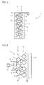
- FIG. 1 shows an inventive arrangement 1, which serves to protect an object such as primarily a motor vehicle, in particular an armored tracked vehicle.
- the arrangement consists of several, in cross-section prism-shaped profile bars, which in two separate rows 2, 3 (see Fig. 2 ) are arranged.
- the profile bars 4 of the first row 2 are superposed and parallel to each other, but spaced from each other.
- the profile bars 5 of the second row 3 are one above the other and parallel to each other extending, but also spaced from each other.
- the two rows 2, 3 are positioned offset in such a way that the profiled bars 4, as seen from the front 6 of the arrangement 1, cover the gaps between two profiled bars 5 of the second row 3 lying behind them. So it looks like, seen from the side, a quasi-closed front.
- the profile bars 4 are shown in cross section square, square in the illustrated example. But they can also be diamond-shaped, or have a cross-sectional shape with even more edges.
- the cross-sectional areas of the profiled bars 4 and 5 may be the same, but they may also differ, in which case preferably the cross-sectional areas of the profiled bars 4 of the first row 2 are smaller than the cross-sectional areas of the profiled bars 5 of the second row 3.
- the distances, seen vertically, between two profile bars 4 and two profile bars 5 may be between 3 to 100 mm, ultimately the concrete selected geometric arrangement of the cross-sectional shape and the cross-sectional area of the individual profile bars depends, since it must be ensured that the profile bars cover the gaps between two profile bars 5.
- the profiled bars 4 and 5 are made of metallic material, they can be solid profiles or hollow profiles, optionally filled (eg with sand or the like). They are preferably made of simple structural steel, so not expensive steel armor. This is because they have a high protective effect, which is not based on outstanding strength properties of the material used, but on a purposeful creation of contours, which serve the fragmentation of an impacting projectile, which then breaks down into a plurality of individual sub-projectiles, which is defined in move created free spaces between the profiled bars 4, 5 and hit there on defined surfaces, so that it comes to a total of a high degree of fragmentation of the impinging projectile, associated with high momentum transfers to the participating profile bars under destruction of kinetic energy of the sub-projectiles such that these sub-projectiles, if at all, only with low penetration power on the underlying armor of the motor vehicle meet and there can do no harm.
- a holder 7 can be seen, in the embodiment shown, see FIG. 1 , two such holders 7 are provided. These have corresponding openings 8, 9, which essentially the Geometry of the profile bars correspond, so that they can be inserted through the opening 8, 9.
- the inserted profile bars 4, 5 can then be welded in their final position on the brackets 7, so that a total of a prefabricated arrangement 1 results, which can be completely installed as such.
- Such an arrangement 1 has for example a length of 1 to 1.5 m, so that it can still be worn. Also allows such a dimension, by juxtaposed attachment of several such arrangement to cover a larger area, for example, a complete side surface of a tank. If the armored front to be protected, it is readily possible, for example, only two such arrangements 1 to install front.
- FIG. 3 shows an inventive arrangement 1, which in the construction of the Figures 1 and 2 equivalent. Also there are two rows 2, 3 consisting of profiled bars 4, 5 are formed, which in turn are received in at least two corresponding holders 7. Again, the inventive row offset is realized.
- Beulbleche 11 are also set here between the corresponding rows, which are optionally used on the two brackets 7 in corresponding receiving slots respectively fixed.
- These Beulblechen 11 may be simple metal sheets, but are also conceivable sandwich structures consisting of a metal layer and an applied plastic or rubber layer or the like.
- These Beulbleche work against additional hollow charge threats.
- Such shaped charges form highly dynamic high-load spikes, which can be greatly disturbed by the integrated Beulbleche.
- these Beulbleche also have against an attack with EFP projectiles, for example, an additional protective function, since they also inevitably act impulsive or energy-dissipating.
- FIG. 4 shows in the form of a schematic diagram of the operation of the inventive arrangement 1, which is shown here only in principle. Shown is the arrangement 1, which is positioned in front of a base armor 12 of a motor vehicle.
- the distance d between the back plane of the assembly 1 and the base armor 12 should be between 20 mm to 2000 mm, with an appropriate distance determined to be (in mm) at least 10 times the numerical value of the minimum cross-sectional area of a profile bar corresponds, provided that all profile bars 4, 5 have the same cross-sectional area, or the cross-sectional area average value. For example, if a profile bar has a cross-sectional area of 36 cm 2 , the distance d should be 360 mm.
- the profile bars 4, 5 are arranged so that in each case an edge 13, 14 in the direction of the approaching threat, here represented by an approaching projectile 15, is directed.
- the square profile bars 4, 5 are thus aligned so that the two diagonals are horizontal and vertical. That is, the respective bar surfaces 16 and 17 are at an angle not equal to 90 ° to horizontal, they are (assuming vertical alignment of the assembly 1) in the example shown at an angle of 45 ° to the horizontal.
- the projectile 15 for example an EFP projectile, encounters the arrangement 1. It strikes a profiled bar 4 of the first row 2 and meets there in the example shown on the projecting edge 13. This leads to a high degree of fragmentation and formation of many individual sub-projectiles 18, resulting from the inclined surfaces 16 after Be distracted at the top and bottom to the side. They move into the defined free spaces formed between the individual profile bars 4, 5 and meet there either on the quasi-inner surfaces 16 of the section bars 4 of the first row 2 or on edges or surfaces 17 of the section bars 5 of the second row 3.
- Beulbleche 11 While in the upper part of FIG. 4 no Beulbleche 11 are shown in the lower part of FIG. 4 exemplarily two Beulbleche 11 shown. These serve as further impact or deflection surfaces for the subprojectiles 18. That is, that to these Beulblechen 11, which are deformed upon impact of the subprojectiles 18, the subprojectiles 18 are braked, even there energy is destroyed.
- FIG. 4 shows the impact of an EFD projectile that can be effectively destroyed and thus reduced in its naturaldringungswin
- the inventive arrangement is also effective against shaped charges or against KE arrow ammunition.
- shaped charges in particular the integration of Beulbleche is appropriate.
- the protective function is also in terms of KE arrow ammunition, again, the effect against these thin, long projectiles based on an asymmetric cross-sectional load. Because the approaching long projectile experiences high shear and bending forces on impact, which break the projectile, so that it also comes here to a fragmentation.
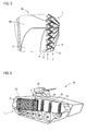
- FIG. 5 shows a schematic diagram of an embodiment of a motor vehicle 19 according to the invention, which is only partially shown here. Shown is the lateral base armor 20 (corresponding to the basic armor 12 off FIG. 4 ) with chainwork 21 located in front of it.
- the arrangement 1 according to the invention shown is placed in front of the basic armor and pulled over the chain mechanism 21.
- the arrangement 1 is as in FIG. 3 shown executed, that is consisting of two rows 2, 3 of profiled bars 4, 5, which are arranged in vertical rows parallel to each other superimposed in the respective rows 2, 3, wherein the rows 2, 3 are positioned offset. Also provided here are the Beulbleche 11, which extend between the section bars 4 respectively 5, extending into the region of the respective other row, are arranged.
- arrangement 1 may be a prefabricated arrangement in the sense of FIGS. 1 to 3 act, in which therefore the profiled bars 4, 5 and possibly the Beulbleche 11 are firmly connected to the brackets 7, so that the entire assembly 1 can be attached as a one-piece component to the vehicle.
- the profiled bars 4, 5 and possibly the Beulbleche 11 are firmly connected to the brackets 7, so that the entire assembly 1 can be attached as a one-piece component to the vehicle.
- three or four such arrangements 1 are positioned side by side. If the vehicle height changes, that is, if the vehicle height decreases toward the front, it is conceivable to design such a prefabricated arrangement correspondingly also for this geometry.
- FIG. 6 shows a motor vehicle 19 according to the invention, in which on a vehicle side already an inventive arrangement 1, which extends over a part of the vehicle side, is shown. In the front side area, no arrangement is shown, but only a plurality of the vehicle either releasably mounted or fixed brackets 22 are shown, whose function ultimately corresponds to the brackets 7, with the difference that on them the profile bars 4, 5 and optionally the Beulbleche 11 not firmly and permanently mounted.
- the brackets 22 also have corresponding openings 23, 24, which serve to receive the profile bars 4, 5 and which are of course formed according to the geometric arrangement or orientation of the profile bars 4, 5 in a row and with the inventive row offset.
- the profiled bars 4, 5 are then inserted into these, if required, and fixed by means of suitable holding means (eg pins, locking pins, clamps, etc.), as is the case with the already installed arrangement 1.
- suitable holding means eg pins, locking pins, clamps, etc.
- brackets 22 are shown only on the side of the vehicle 19, it is of course conceivable to provide corresponding brackets in the area of the vehicle front and the rear of the vehicle, so that there is the possibility, there also corresponding profile bars 4, 5 to install.
- the illustrated brackets 22 are merely exemplary in nature. Of course, the specific geometry or design of such a holder may also be different. It only has to be able to securely hold the corresponding profile bars 4, 5 and possibly the bump plates 11 in the spatial arrangement provided according to the invention, so that the corresponding profile bar rows can be formed with the row offset according to the invention. Also, in principle, the attachment of an arrangement or positioning vehicle-side brackets is not limited to the two sides and the front-rear section. Rather, an arrangement on corresponding top or roof surfaces is conceivable to provide effective protection against approaching projectiles from above.
Applications Claiming Priority (1)
| Application Number | Priority Date | Filing Date | Title |
|---|---|---|---|
| DE102013008941.7A DE102013008941A1 (de) | 2013-05-25 | 2013-05-25 | Anordnung zum Schutz eines Objekts, insbesondere eines Kraftfahrzeugs, gegen anfliegende Projektile |
Publications (3)
| Publication Number | Publication Date |
|---|---|
| EP2806245A1 true EP2806245A1 (fr) | 2014-11-26 |
| EP2806245B1 EP2806245B1 (fr) | 2017-12-20 |
| EP2806245B8 EP2806245B8 (fr) | 2018-02-21 |
Family
ID=50687242
Family Applications (1)
| Application Number | Title | Priority Date | Filing Date |
|---|---|---|---|
| EP14001632.0A Revoked EP2806245B8 (fr) | 2013-05-25 | 2014-05-08 | Dispositif de protection contre des projectiles |
Country Status (5)
| Country | Link |
|---|---|
| US (1) | US20140373707A1 (fr) |
| EP (1) | EP2806245B8 (fr) |
| CA (1) | CA2851799A1 (fr) |
| DE (1) | DE102013008941A1 (fr) |
| IL (1) | IL232092A0 (fr) |
Families Citing this family (4)
| Publication number | Priority date | Publication date | Assignee | Title |
|---|---|---|---|---|
| US9194662B1 (en) * | 2013-03-15 | 2015-11-24 | Peter D. Poulsen | Article for dispersing energy of a blast or impact |
| DE102014014468A1 (de) * | 2014-09-26 | 2016-03-31 | Rheinmetall Waffe Munition Gmbh | Militärisches Radfahrzeug mit einer Minenschutzanordnung |
| US20160209178A1 (en) * | 2015-01-16 | 2016-07-21 | Falcon Power, LLC | Ballistic armor |
| US10012479B2 (en) * | 2016-02-22 | 2018-07-03 | Michael Boviall | Ballistic barrier |
Citations (7)
| Publication number | Priority date | Publication date | Assignee | Title |
|---|---|---|---|---|
| EP0041271A1 (fr) * | 1980-06-02 | 1981-12-09 | Alvin Eugene Gorum | Blindage composite à base de matériaux céramiques |
| FR2747719A1 (fr) * | 1988-06-29 | 1997-10-24 | Francois Conversy | Dispositif de protection des abris contre l'impact direct des projectiles conventionnels |
| EP0897097A2 (fr) * | 1997-08-13 | 1999-02-17 | Gerd Kellner | Plaque composite pour la protection contre les mines terrestres |
| DE19825260B4 (de) | 1998-06-05 | 2007-02-08 | Geke Technologie Gmbh | Anordnung zum Schutz von Objekten gegen geformte Ladungen |
| US20090031889A1 (en) * | 2007-05-18 | 2009-02-05 | Saul W Venner | Complex Geometry Composite Armor for Military Applications |
| US20110072960A1 (en) * | 2007-11-16 | 2011-03-31 | Composite Technologies | Armor shielding |
| US20110232472A1 (en) * | 2010-03-25 | 2011-09-29 | General Atomics | Bar armor system for protecting against rocket-propelled grenades |
Family Cites Families (25)
| Publication number | Priority date | Publication date | Assignee | Title |
|---|---|---|---|---|
| US2393350A (en) * | 1943-05-21 | 1946-01-22 | George P Wiedman | Bullet protection guard |
| US2392215A (en) | 1944-11-17 | 1946-01-01 | Barber Colman Co | Bulletproof grid |
| US2492294A (en) | 1947-04-08 | 1949-12-27 | Barber Colman Co | Air entrance grid |
| US3137205A (en) * | 1959-02-04 | 1964-06-16 | Bofors Ab | Device for protection against bursting projectiles |
| GB865629A (en) | 1959-02-04 | 1961-04-19 | Bofors Ab | A protective device for reducing the effect of projectiles with bursting charges |
| US3431818A (en) * | 1965-04-26 | 1969-03-11 | Aerojet General Co | Lightweight protective armor plate |
| DE1578345B2 (de) * | 1967-02-11 | 1975-02-13 | Dr.-Ing.H.C. F. Porsche Ag, 7000 Stuttgart | Gräting zur beschuBsicheren Abdeckung von Luftein· und -austrittsöffnungen von Panzerfahrzeugen |
| US3765301A (en) * | 1968-06-09 | 1973-10-16 | Us Army | Light weight ribbed composite armor |
| US3765299A (en) * | 1968-09-06 | 1973-10-16 | Us Army | Universal applique armor |
| US4325283A (en) * | 1980-03-19 | 1982-04-20 | Cadillac Gage Company | Armored grille |
| US4727789A (en) * | 1986-06-24 | 1988-03-01 | T & E International, Inc. | Vented suppressive shielding |
| DE3703716A1 (de) * | 1987-02-06 | 1988-08-18 | Hoesch Ag | Vorrichtung zur sicheren abdeckung von luftoeffnungen in sonderfahrzeugen |
| US4957034A (en) * | 1989-12-15 | 1990-09-18 | The United States Of America As Represented By The Secretary Of The Army | Candy cane configuration for modular armor unit |
| DE4237798C2 (de) * | 1992-11-03 | 1995-12-07 | Ela Bs Ges Fuer Besondere Sich | Panzerung |
| US5413027A (en) * | 1993-03-19 | 1995-05-09 | The United States Of America As Represented By The Secretary Of The Army | Reactive armor with radar absorbing structure |
| US5405673A (en) * | 1993-03-30 | 1995-04-11 | Seibert; George M. | Shooting range backstop |
| KR100255413B1 (ko) * | 1995-03-15 | 2000-05-01 | 프리트 | 특수차량용 방탄그릴 |
| US5880394A (en) * | 1995-03-15 | 1999-03-09 | Fried, Krupp Ag Hoesch-Krupp | Ballistic grill for special purpose vehicles |
| DE19634227C1 (de) * | 1996-08-23 | 1998-01-08 | Krupp Ag Hoesch Krupp | Verbindung eines Rahmens einer Gräting für Sonderfahrzeuge, wie gepanzerte Fahrzeuge, mit den Profilleisten der Gräting |
| EP2076731A2 (fr) | 2006-07-31 | 2009-07-08 | BAE SYSTEMS Information and Electronic Systems Integration, Inc. | Dispositif et procédé de protection d'un véhicule contre des grenades propulsées par fusée |
| AU2008272461A1 (en) * | 2007-07-05 | 2009-01-08 | Bae Systems Land Systems South Africa (Pty) Limited | Armour arrangement |
| CA2923361C (fr) | 2008-08-11 | 2018-10-09 | Greenhill Antiballistics Corporation | Materiau composite |
| GB2483267B (en) * | 2010-09-02 | 2014-10-15 | Bae Systems Plc | Armour assembly |
| SE535388C2 (sv) * | 2010-11-17 | 2012-07-17 | Bae Systems Haegglunds Ab | Anordning för skydd mot RSV-granater och fordon med sådan anordning |
| US20140123842A1 (en) * | 2012-03-06 | 2014-05-08 | Meggitt (Rockmart) Inc. | Blast shield |
-
2013
- 2013-05-25 DE DE102013008941.7A patent/DE102013008941A1/de not_active Ceased
-
2014
- 2014-04-13 IL IL232092A patent/IL232092A0/en not_active IP Right Cessation
- 2014-05-08 EP EP14001632.0A patent/EP2806245B8/fr not_active Revoked
- 2014-05-14 CA CA2851799A patent/CA2851799A1/fr not_active Abandoned
- 2014-05-22 US US14/284,891 patent/US20140373707A1/en not_active Abandoned
Patent Citations (7)
| Publication number | Priority date | Publication date | Assignee | Title |
|---|---|---|---|---|
| EP0041271A1 (fr) * | 1980-06-02 | 1981-12-09 | Alvin Eugene Gorum | Blindage composite à base de matériaux céramiques |
| FR2747719A1 (fr) * | 1988-06-29 | 1997-10-24 | Francois Conversy | Dispositif de protection des abris contre l'impact direct des projectiles conventionnels |
| EP0897097A2 (fr) * | 1997-08-13 | 1999-02-17 | Gerd Kellner | Plaque composite pour la protection contre les mines terrestres |
| DE19825260B4 (de) | 1998-06-05 | 2007-02-08 | Geke Technologie Gmbh | Anordnung zum Schutz von Objekten gegen geformte Ladungen |
| US20090031889A1 (en) * | 2007-05-18 | 2009-02-05 | Saul W Venner | Complex Geometry Composite Armor for Military Applications |
| US20110072960A1 (en) * | 2007-11-16 | 2011-03-31 | Composite Technologies | Armor shielding |
| US20110232472A1 (en) * | 2010-03-25 | 2011-09-29 | General Atomics | Bar armor system for protecting against rocket-propelled grenades |
Also Published As
| Publication number | Publication date |
|---|---|
| EP2806245B1 (fr) | 2017-12-20 |
| EP2806245B8 (fr) | 2018-02-21 |
| CA2851799A1 (fr) | 2014-11-25 |
| US20140373707A1 (en) | 2014-12-25 |
| IL232092A0 (en) | 2014-08-31 |
| DE102013008941A1 (de) | 2014-11-27 |
Similar Documents
| Publication | Publication Date | Title |
|---|---|---|
| EP1944565B1 (fr) | Dispositif de défense contre les projectiles à charge creuse | |
| EP1566607B1 (fr) | Plancher d'un véhicule pour la protection contre les mines terrestres | |
| EP0897097B1 (fr) | Plaque composite pour la protection contre les mines terrestres | |
| EP1002213B1 (fr) | Systeme pour proteger des objets de charges formees | |
| EP2382437B1 (fr) | Protection d'objet contre des charges creuses et procédé de fabrication | |
| EP2806245B1 (fr) | Dispositif de protection contre des projectiles | |
| EP2275361A1 (fr) | Equipement de protection pour conteneur, conteneur et ensemble de conteneurs | |
| EP2020585B1 (fr) | Blindage de type SLAT mobile et de préférence amovible pour véhicules | |
| EP1499846B1 (fr) | Dispositif de protection pour vehicules blindes, en particulier contre les projectiles a charge creuse | |
| DE112010000809T5 (de) | Dämpfungsaufhängung mit der Möglichkeit zum Heben für ein Zusatz-Bewehrungssystem | |
| DE102012103036A1 (de) | Gehäuse, insbesondere gegen Detonationswirkung geschütztes Fahrzeuggehäuse | |
| EP2275773B1 (fr) | Protection contre les mines | |
| EP2661527B1 (fr) | Système de protection pour parois de bâtiment ou de conteneur | |
| EP3128283B1 (fr) | Élément de protection pour assurer une protection contre des projectiles balistiques et véhicule militaire | |
| EP3904600B1 (fr) | Barrière mobile de véhicule destinée à l'installation sur une surface plane | |
| EP2226603A2 (fr) | Dispositif de protection destiné à protéger un objet contre des mines formant des projectiles | |
| DE10318492B4 (de) | Vorrichtung zum Schutz eines Objekts | |
| EP1182421B1 (fr) | Système de protection pour un véhicule contre les effets d'une charge explosive | |
| DE3729211C1 (de) | Reaktive Panzerung | |
| DE60223077T2 (de) | Minenräumpflug | |
| EP3992569B1 (fr) | Plaque de protection | |
| EP4045868B1 (fr) | Châssis de véhicule avec protection contre les mines | |
| DE202012011496U1 (de) | Durchschlagschutz | |
| EP2555278B1 (fr) | Boîtier en tôle d'acier | |
| DE102010028933A1 (de) | Schutzwand |
Legal Events
| Date | Code | Title | Description |
|---|---|---|---|
| PUAI | Public reference made under article 153(3) epc to a published international application that has entered the european phase |
Free format text: ORIGINAL CODE: 0009012 |
|
| 17P | Request for examination filed |
Effective date: 20140508 |
|
| AK | Designated contracting states |
Kind code of ref document: A1 Designated state(s): AL AT BE BG CH CY CZ DE DK EE ES FI FR GB GR HR HU IE IS IT LI LT LU LV MC MK MT NL NO PL PT RO RS SE SI SK SM TR |
|
| AX | Request for extension of the european patent |
Extension state: BA ME |
|
| R17P | Request for examination filed (corrected) |
Effective date: 20150508 |
|
| RBV | Designated contracting states (corrected) |
Designated state(s): AL AT BE BG CH CY CZ DE DK EE ES FI FR GB GR HR HU IE IS IT LI LT LU LV MC MK MT NL NO PL PT RO RS SE SI SK SM TR |
|
| 17Q | First examination report despatched |
Effective date: 20151214 |
|
| STAA | Information on the status of an ep patent application or granted ep patent |
Free format text: STATUS: EXAMINATION IS IN PROGRESS |
|
| RAP1 | Party data changed (applicant data changed or rights of an application transferred) |
Owner name: DIEHL DEFENCE GMBH & CO. KG Owner name: HERDEN-OSTENDORFF, MARCO |
|
| GRAP | Despatch of communication of intention to grant a patent |
Free format text: ORIGINAL CODE: EPIDOSNIGR1 |
|
| STAA | Information on the status of an ep patent application or granted ep patent |
Free format text: STATUS: GRANT OF PATENT IS INTENDED |
|
| RIC1 | Information provided on ipc code assigned before grant |
Ipc: F41H 5/013 20060101AFI20170620BHEP Ipc: F41H 5/04 20060101ALI20170620BHEP Ipc: F41H 7/04 20060101ALI20170620BHEP Ipc: F41H 5/02 20060101ALI20170620BHEP |
|
| INTG | Intention to grant announced |
Effective date: 20170706 |
|
| GRAS | Grant fee paid |
Free format text: ORIGINAL CODE: EPIDOSNIGR3 |
|
| GRAA | (expected) grant |
Free format text: ORIGINAL CODE: 0009210 |
|
| STAA | Information on the status of an ep patent application or granted ep patent |
Free format text: STATUS: THE PATENT HAS BEEN GRANTED |
|
| AK | Designated contracting states |
Kind code of ref document: B1 Designated state(s): AL AT BE BG CH CY CZ DE DK EE ES FI FR GB GR HR HU IE IS IT LI LT LU LV MC MK MT NL NO PL PT RO RS SE SI SK SM TR |
|
| REG | Reference to a national code |
Ref country code: GB Ref legal event code: FG4D Free format text: NOT ENGLISH |
|
| REG | Reference to a national code |
Ref country code: CH Ref legal event code: EP |
|
| REG | Reference to a national code |
Ref country code: IE Ref legal event code: FG4D Free format text: LANGUAGE OF EP DOCUMENT: GERMAN |
|
| REG | Reference to a national code |
Ref country code: AT Ref legal event code: REF Ref document number: 956764 Country of ref document: AT Kind code of ref document: T Effective date: 20180115 |
|
| REG | Reference to a national code |
Ref country code: DE Ref legal event code: R096 Ref document number: 502014006622 Country of ref document: DE |
|
| RIN2 | Information on inventor provided after grant (corrected) |
Inventor name: HERDEN-OSTENDORFF, MARCO Inventor name: SCHLUETER, KLAUS |
|
| REG | Reference to a national code |
Ref country code: SE Ref legal event code: TRGR |
|
| REG | Reference to a national code |
Ref country code: NL Ref legal event code: MP Effective date: 20171220 |
|
| PG25 | Lapsed in a contracting state [announced via postgrant information from national office to epo] |
Ref country code: FI Free format text: LAPSE BECAUSE OF FAILURE TO SUBMIT A TRANSLATION OF THE DESCRIPTION OR TO PAY THE FEE WITHIN THE PRESCRIBED TIME-LIMIT Effective date: 20171220 Ref country code: LT Free format text: LAPSE BECAUSE OF FAILURE TO SUBMIT A TRANSLATION OF THE DESCRIPTION OR TO PAY THE FEE WITHIN THE PRESCRIBED TIME-LIMIT Effective date: 20171220 Ref country code: NO Free format text: LAPSE BECAUSE OF FAILURE TO SUBMIT A TRANSLATION OF THE DESCRIPTION OR TO PAY THE FEE WITHIN THE PRESCRIBED TIME-LIMIT Effective date: 20180320 |
|
| REG | Reference to a national code |
Ref country code: LT Ref legal event code: MG4D |
|
| REG | Reference to a national code |
Ref country code: FR Ref legal event code: PLFP Year of fee payment: 5 |
|
| PG25 | Lapsed in a contracting state [announced via postgrant information from national office to epo] |
Ref country code: GR Free format text: LAPSE BECAUSE OF FAILURE TO SUBMIT A TRANSLATION OF THE DESCRIPTION OR TO PAY THE FEE WITHIN THE PRESCRIBED TIME-LIMIT Effective date: 20180321 Ref country code: LV Free format text: LAPSE BECAUSE OF FAILURE TO SUBMIT A TRANSLATION OF THE DESCRIPTION OR TO PAY THE FEE WITHIN THE PRESCRIBED TIME-LIMIT Effective date: 20171220 Ref country code: BG Free format text: LAPSE BECAUSE OF FAILURE TO SUBMIT A TRANSLATION OF THE DESCRIPTION OR TO PAY THE FEE WITHIN THE PRESCRIBED TIME-LIMIT Effective date: 20180320 Ref country code: RS Free format text: LAPSE BECAUSE OF FAILURE TO SUBMIT A TRANSLATION OF THE DESCRIPTION OR TO PAY THE FEE WITHIN THE PRESCRIBED TIME-LIMIT Effective date: 20171220 Ref country code: HR Free format text: LAPSE BECAUSE OF FAILURE TO SUBMIT A TRANSLATION OF THE DESCRIPTION OR TO PAY THE FEE WITHIN THE PRESCRIBED TIME-LIMIT Effective date: 20171220 |
|
| PG25 | Lapsed in a contracting state [announced via postgrant information from national office to epo] |
Ref country code: NL Free format text: LAPSE BECAUSE OF FAILURE TO SUBMIT A TRANSLATION OF THE DESCRIPTION OR TO PAY THE FEE WITHIN THE PRESCRIBED TIME-LIMIT Effective date: 20171220 |
|
| PG25 | Lapsed in a contracting state [announced via postgrant information from national office to epo] |
Ref country code: SK Free format text: LAPSE BECAUSE OF FAILURE TO SUBMIT A TRANSLATION OF THE DESCRIPTION OR TO PAY THE FEE WITHIN THE PRESCRIBED TIME-LIMIT Effective date: 20171220 Ref country code: CZ Free format text: LAPSE BECAUSE OF FAILURE TO SUBMIT A TRANSLATION OF THE DESCRIPTION OR TO PAY THE FEE WITHIN THE PRESCRIBED TIME-LIMIT Effective date: 20171220 Ref country code: ES Free format text: LAPSE BECAUSE OF FAILURE TO SUBMIT A TRANSLATION OF THE DESCRIPTION OR TO PAY THE FEE WITHIN THE PRESCRIBED TIME-LIMIT Effective date: 20171220 Ref country code: CY Free format text: LAPSE BECAUSE OF FAILURE TO SUBMIT A TRANSLATION OF THE DESCRIPTION OR TO PAY THE FEE WITHIN THE PRESCRIBED TIME-LIMIT Effective date: 20171220 Ref country code: EE Free format text: LAPSE BECAUSE OF FAILURE TO SUBMIT A TRANSLATION OF THE DESCRIPTION OR TO PAY THE FEE WITHIN THE PRESCRIBED TIME-LIMIT Effective date: 20171220 |
|
| PG25 | Lapsed in a contracting state [announced via postgrant information from national office to epo] |
Ref country code: RO Free format text: LAPSE BECAUSE OF FAILURE TO SUBMIT A TRANSLATION OF THE DESCRIPTION OR TO PAY THE FEE WITHIN THE PRESCRIBED TIME-LIMIT Effective date: 20171220 Ref country code: IS Free format text: LAPSE BECAUSE OF FAILURE TO SUBMIT A TRANSLATION OF THE DESCRIPTION OR TO PAY THE FEE WITHIN THE PRESCRIBED TIME-LIMIT Effective date: 20180420 Ref country code: PL Free format text: LAPSE BECAUSE OF FAILURE TO SUBMIT A TRANSLATION OF THE DESCRIPTION OR TO PAY THE FEE WITHIN THE PRESCRIBED TIME-LIMIT Effective date: 20171220 Ref country code: SM Free format text: LAPSE BECAUSE OF FAILURE TO SUBMIT A TRANSLATION OF THE DESCRIPTION OR TO PAY THE FEE WITHIN THE PRESCRIBED TIME-LIMIT Effective date: 20171220 |
|
| REG | Reference to a national code |
Ref country code: DE Ref legal event code: R026 Ref document number: 502014006622 Country of ref document: DE |
|
| PG25 | Lapsed in a contracting state [announced via postgrant information from national office to epo] |
Ref country code: MT Free format text: LAPSE BECAUSE OF FAILURE TO SUBMIT A TRANSLATION OF THE DESCRIPTION OR TO PAY THE FEE WITHIN THE PRESCRIBED TIME-LIMIT Effective date: 20171220 |
|
| PLBI | Opposition filed |
Free format text: ORIGINAL CODE: 0009260 |
|
| PLAX | Notice of opposition and request to file observation + time limit sent |
Free format text: ORIGINAL CODE: EPIDOSNOBS2 |
|
| 26 | Opposition filed |
Opponent name: RHEINMETALL WAFFE MUNITION GMBH Effective date: 20180920 |
|
| PG25 | Lapsed in a contracting state [announced via postgrant information from national office to epo] |
Ref country code: DK Free format text: LAPSE BECAUSE OF FAILURE TO SUBMIT A TRANSLATION OF THE DESCRIPTION OR TO PAY THE FEE WITHIN THE PRESCRIBED TIME-LIMIT Effective date: 20171220 |
|
| REG | Reference to a national code |
Ref country code: BE Ref legal event code: MM Effective date: 20180531 |
|
| PG25 | Lapsed in a contracting state [announced via postgrant information from national office to epo] |
Ref country code: MC Free format text: LAPSE BECAUSE OF FAILURE TO SUBMIT A TRANSLATION OF THE DESCRIPTION OR TO PAY THE FEE WITHIN THE PRESCRIBED TIME-LIMIT Effective date: 20171220 |
|
| PLBB | Reply of patent proprietor to notice(s) of opposition received |
Free format text: ORIGINAL CODE: EPIDOSNOBS3 |
|
| REG | Reference to a national code |
Ref country code: IE Ref legal event code: MM4A |
|
| PG25 | Lapsed in a contracting state [announced via postgrant information from national office to epo] |
Ref country code: SI Free format text: LAPSE BECAUSE OF FAILURE TO SUBMIT A TRANSLATION OF THE DESCRIPTION OR TO PAY THE FEE WITHIN THE PRESCRIBED TIME-LIMIT Effective date: 20171220 |
|
| PG25 | Lapsed in a contracting state [announced via postgrant information from national office to epo] |
Ref country code: LU Free format text: LAPSE BECAUSE OF NON-PAYMENT OF DUE FEES Effective date: 20180508 |
|
| PG25 | Lapsed in a contracting state [announced via postgrant information from national office to epo] |
Ref country code: IE Free format text: LAPSE BECAUSE OF NON-PAYMENT OF DUE FEES Effective date: 20180508 |
|
| PG25 | Lapsed in a contracting state [announced via postgrant information from national office to epo] |
Ref country code: BE Free format text: LAPSE BECAUSE OF NON-PAYMENT OF DUE FEES Effective date: 20180531 |
|
| PGFP | Annual fee paid to national office [announced via postgrant information from national office to epo] |
Ref country code: IT Payment date: 20190527 Year of fee payment: 6 |
|
| PGFP | Annual fee paid to national office [announced via postgrant information from national office to epo] |
Ref country code: FR Payment date: 20190523 Year of fee payment: 6 Ref country code: SE Payment date: 20190521 Year of fee payment: 6 |
|
| PGFP | Annual fee paid to national office [announced via postgrant information from national office to epo] |
Ref country code: CH Payment date: 20190521 Year of fee payment: 6 |
|
| PGFP | Annual fee paid to national office [announced via postgrant information from national office to epo] |
Ref country code: DE Payment date: 20190717 Year of fee payment: 6 Ref country code: GB Payment date: 20190521 Year of fee payment: 6 |
|
| REG | Reference to a national code |
Ref country code: DE Ref legal event code: R064 Ref document number: 502014006622 Country of ref document: DE Ref country code: DE Ref legal event code: R103 Ref document number: 502014006622 Country of ref document: DE |
|
| RDAF | Communication despatched that patent is revoked |
Free format text: ORIGINAL CODE: EPIDOSNREV1 |
|
| PG25 | Lapsed in a contracting state [announced via postgrant information from national office to epo] |
Ref country code: TR Free format text: LAPSE BECAUSE OF FAILURE TO SUBMIT A TRANSLATION OF THE DESCRIPTION OR TO PAY THE FEE WITHIN THE PRESCRIBED TIME-LIMIT Effective date: 20171220 |
|
| PG25 | Lapsed in a contracting state [announced via postgrant information from national office to epo] |
Ref country code: HU Free format text: LAPSE BECAUSE OF FAILURE TO SUBMIT A TRANSLATION OF THE DESCRIPTION OR TO PAY THE FEE WITHIN THE PRESCRIBED TIME-LIMIT; INVALID AB INITIO Effective date: 20140508 Ref country code: PT Free format text: LAPSE BECAUSE OF FAILURE TO SUBMIT A TRANSLATION OF THE DESCRIPTION OR TO PAY THE FEE WITHIN THE PRESCRIBED TIME-LIMIT Effective date: 20171220 |
|
| PG25 | Lapsed in a contracting state [announced via postgrant information from national office to epo] |
Ref country code: MK Free format text: LAPSE BECAUSE OF NON-PAYMENT OF DUE FEES Effective date: 20171220 |
|
| RDAG | Patent revoked |
Free format text: ORIGINAL CODE: 0009271 |
|
| STAA | Information on the status of an ep patent application or granted ep patent |
Free format text: STATUS: PATENT REVOKED |
|
| PG25 | Lapsed in a contracting state [announced via postgrant information from national office to epo] |
Ref country code: AL Free format text: LAPSE BECAUSE OF FAILURE TO SUBMIT A TRANSLATION OF THE DESCRIPTION OR TO PAY THE FEE WITHIN THE PRESCRIBED TIME-LIMIT Effective date: 20171220 |
|
| REG | Reference to a national code |
Ref country code: CH Ref legal event code: PL |
|
| REG | Reference to a national code |
Ref country code: FI Ref legal event code: MGE |
|
| 27W | Patent revoked |
Effective date: 20191218 |
|
| GBPR | Gb: patent revoked under art. 102 of the ep convention designating the uk as contracting state |
Effective date: 20191218 |
|
| REG | Reference to a national code |
Ref country code: AT Ref legal event code: MM01 Ref document number: 956764 Country of ref document: AT Kind code of ref document: T Effective date: 20190508 |
|
| REG | Reference to a national code |
Ref country code: SE Ref legal event code: ECNC |
|
| REG | Reference to a national code |
Ref country code: AT Ref legal event code: MA03 Ref document number: 956764 Country of ref document: AT Kind code of ref document: T Effective date: 20191218 |